

Page 1

HP E1409B
C-Size VXIbus Chassis Shield
Installation Guide
HP 75000 Series C
*E1409-90003*
Manual Part Number: E1409-900 03
Printed in U.S.A. E1096
Page 2

Notes
Page 3

Certification
Hewlett-Packard Company certifies that this product met its published s peci fica t ions at the time of shipm e nt from th e fact ory. Hewlet tPackard further certifi es that its calibrat ion mea sureme nt s are tracea ble to the Unit ed Sta tes Na tion al Institut e of Standards and Technology (formerly National Bureau of Standards), to the extent allowed by that organization’s calibration facility, and to the calibration
facilities of other International Standards Organization members.
Warranty
This Hewlet t-Pa ck ar d product is warr ante d agai nst de fect s in mate rials and w orkmansh ip for a period of three years from date of shipment. Duration and condit i ons of warranty for this product may be super se ded when the product is integrated into ( becomes a part of)
other HP product s. Du ring the warranty period, Hewlett -Pa ckard Company will, at its option, ei th er repai r or repl ace products whi ch
prove to be defective.
For warranty se r vice or repair, this product must be returned to a service faci l ity designated by Hewlett-Packar d (HP). Buyer sha l l prepay shipping cha rges to HP and HP shal l pay shipping charges t o re tu rn the product to B uyer. However, Buyer shall pay all ship ping
charges, duties, and taxe s for products returned to HP from anot her count r y.
HP warrants that its softwar e and firmwar e designa ted b y HP for use with a product will execute its programmin g instru cti ons wh en
properly installe d on that product. HP does not warrant that the operat ion of the product, or software , or firmware will be uninterrupted
or er ro r f r ee.
Limitation Of Warrant y
The foreg oin g warra nt y sh al l not apply t o defects resulting from i mproper or inadequate mainte nance by Buyer, Buyer-supplied pr oducts or interfacing, unauthori ze d m odificati on or misus e, operation outside of the environmenta l specificat i ons for the product, or improper site prep arat i on or maint ena nce.
The design and imp le mentation of any circuit on this product is the sole responsibility of th e Buyer. HP does not warrant th e Buyer’s
circuitr y or malfunctions of HP products that result from the Bu yer’s circuitry. In addition, HP does not warrant any damage that occurs as a result of the B uyer’s circuit or an y defects th at re sult fr om Buyer-supplied product s.
NO OTHER WARRANTY IS EXPRESSED OR IMPLIED. HP SPECIFICALLY DISCLAIMS THE IMPLIED W ARRANT IES OF
MERCHANTABILITY AND FITNESS FOR A PARTICULAR PURPOSE.
Exclusive Remedie s
THE REMED IES PROVIDED HEREIN ARE BUYER’S SOLE AND EXCLUSIVE REMEDIES. HP SHALL NOT BE LIABLE
FOR ANY DIRECT, INDIRECT, SPECIAL, INCIDENTAL, OR CONSEQUENTIAL DAMAGES, WHETHER BASED ON CONTRACT, TORT, OR ANY OTHER LEGAL THEORY.
Notice
The information contained in this document is subject to change without notice. HEWLETT-PACKARD (HP) MAKES NO W ARRANTY OF ANY KIND W ITH REGARD TO THIS MATERIAL, INCLUDING, BUT NOT LIMITED TO, THE IMPLIED WARRANTIES OF MERCHANTABILITY AND FITNESS FOR A PARTICULAR PURPOSE. HP shall not be liable for errors contained
herein or for incidental or consequential damages in connection with the furnishing, performance or use of this material. This document c ontains proprieta ry informati on which is protected by cop yright. All rights are reserved. No part of this d ocument may be photocopied, reproduced, or translate d to another lan guage wit h out the prior written consent of Hewlett -Packar d C ompany. HP assumes no
responsibility for the use or reliability of its software on equipment that is not furnished by HP.
U.S. Government Restricted Rights
The Software and Do cumentat ion have been devel ope d entir ely at privat e expe nse. The y are delivered and license d as "c omme rcia l
computer software" as defined in DF ARS 252. 227-7013 (October 1988), D F ARS 252.211.701 5 (Ma y 1991) or DFARS 252.227 -7014
(June 1995), as a "comme rcia l item" as defined in F AR 2.101(a), or as "Restrict e d comp uter software " as define d in F AR 52.227 -19
(June 1987) (or any equival en t agen cy re gula tion or c ontract cla use ), which e ver is appli ca ble. You have only those right s provided for
such Software and D ocum ent at ion by the applicable FA R or D FARS clause or the H P st andar d software agreement for t he product involved.
HP E1409B Installation Guide
Copyright © 1996 He wle tt-Pa cka rd Company. All Right s Reser ve d.
Edition 2
HP E1409B Installation Guide 3
Page 4
Documentatio n History
All Editions and Updates of this manual and their creation date are listed below. The first Edition of the manual is Edition 1. The Edition number increment s by 1 whenever the manua l is revised . Updates , which are issued betw een Edi ti ons, c ontain repla ce ment pa ges
to correct or add additional information to the current Edition of the manual. Whenever a new Edition is created, it wil l contain all of
the Update inf ormat ion for the pre viou s Editi on. Each new Ed iti on or Update also incl ude s a revis ed c op y of this documentation history page.
Edition 1 . . . . . . . . . . . . . . . . . . . . . . . . . . . . . . . . . . . . . . . . . . . Sept e mber 1992
Edition 2 . . . . . . . . . . . . . . . . . . . . . . . . . . . . . . . . . . . . . . . . . . . . . October 1996
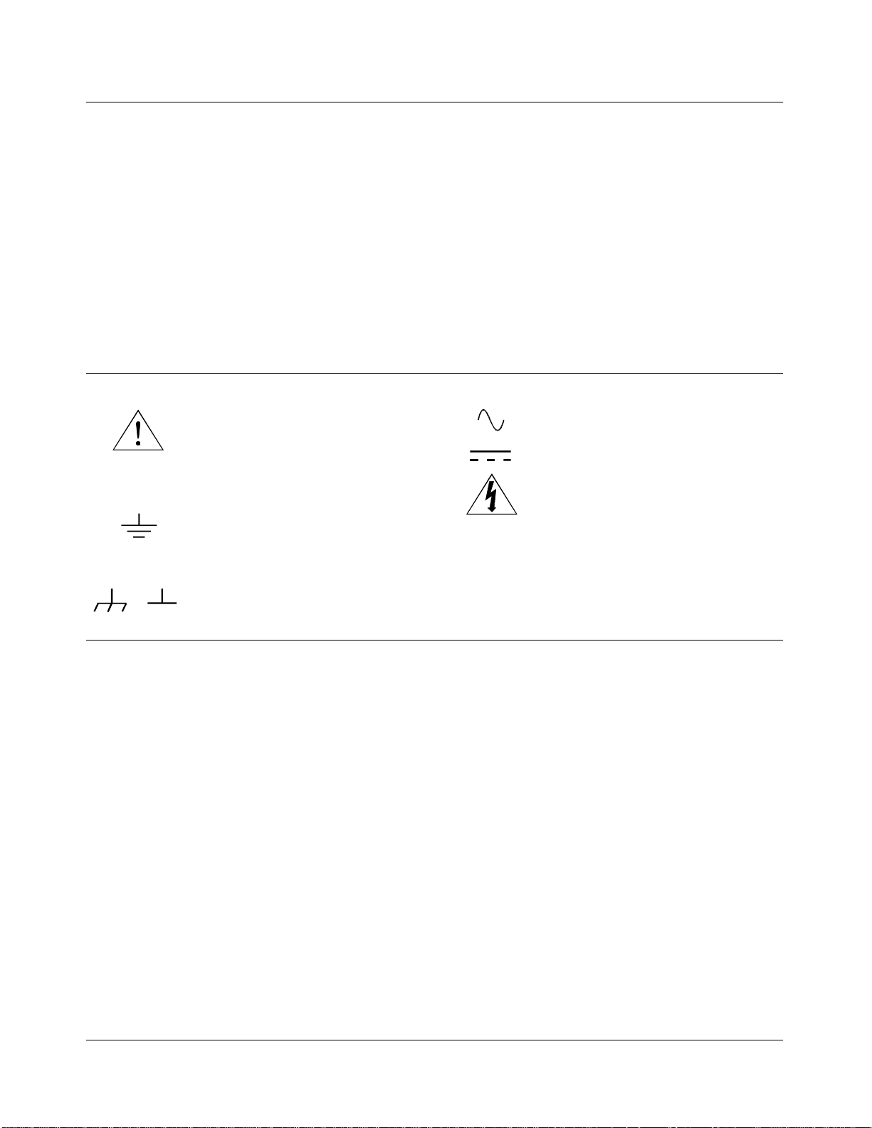
Safety Symbols
Instruction manual symbol affixed to product. Indicat es that the user must re fe r t o t he
manual for specific WARNING or CAUTION information to avoid personal injury
or damage to the product.
Indicates the field wiring terminal that must
be connected to earth ground before operating the equipment—protects against electrical shock in case of fault.
Frame or chassis ground termi nal — t ypi-
or
cally connects to the equipment’s metal
frame.
WARNING
CAUTION
Alternating current (AC).
Direct curren t (DC).
Indicate s ha za rdous voltage s.
Calls at te nt i on t o a pr ocedure, practice, or
condition that could cause bodily injury or
death.
Calls at te nt i on t o a pr ocedure, practice, or c ondition that could possibly cause damage to
equipme nt or perma nen t los s of data.
WARNINGS
The following ge ner al safet y prec aut ions mus t be observed du ring al l phas es of oper ation , ser vice , and repai r of this pr oduct.
Failure to comply with these precautions or with specific warnings elsewhere in this manual violates safety standards of design,
manufacture, and inten ded use of the product. Hewlett-Pac kar d Company assumes no liability for the cust o mer’s fai lu re to
comply with these requirements.
Ground the equipment: For Safety Cl as s 1 equipmen t (equ ipment ha vin g a protective ea rth ter mi nal) , an unint erru ptib le sa fety earth
ground must be provide d from the ma in s power sour ce to the produ ct input wi rin g termi nals or suppli ed power cable .
DO NOT operate the produc t in an explosive at mospher e or in the presen ce of flammable gases or fume s.
For continued protect ion a gainst fire, repl ace the line fuse (s) only with fuse(s) of the same voltage and curre nt rating and type.
DO NOT use repaired fuses or short-circui ted fuse holders.
Keep away from live circuits: Operatin g personnel must not remove equipment covers or shields. Procedures involving the removal
of covers or shields are for use by service-trained personn el onl y. Unde r ce rta in c onditi ons , danger ous v oltage s m ay exist even with the
equipment switched off. To avoid dangerous ele ctrical shock , DO NOT perf orm procedures involving cover or shield removal unless
you are qualified to do so.
DO NOT operate damaged equipment: Whene ver it i s p ossibl e tha t the sa fe ty protection features buil t int o t hi s product have been impaired, eithe r t hr ough physical da m age, excessive mois t ure , or any other reason, REMOVE POWER and do not use the product until
safe operation can be verified by service-trained personnel. If necessary, return the produ ct to a Hewlett -Packar d Sa les and Ser vice Office for service and repair to ensure that safety features are maintaine d.
DO NOT service or adjust alon e: Do not attempt internal service or adjustment unless another person, capable of rendering first aid
and resuscitation, is present.
DO NOT substitute parts or modify equipment: Because of the danger of introducing additional hazar ds, do not install substitute
parts or perform any unauthorized modifica tion to the product. Retur n the product to a Hewlet t-P ackar d Sales and Ser vice O ffice for
service and repair to ensure th at sa fe ty features are ma i nt ai ned.
4 HP E1409B Installation Guide
Page 5
Introduction
WARNING SHOCK HAZARD. Only service-trained perso nn el who are aware of
CAUTION Chassis shield guide installations between slots 2 and 3, 5 and 6, or 9
NOTE This guide shows how to install a single chassis shield between slots 0 and 1.
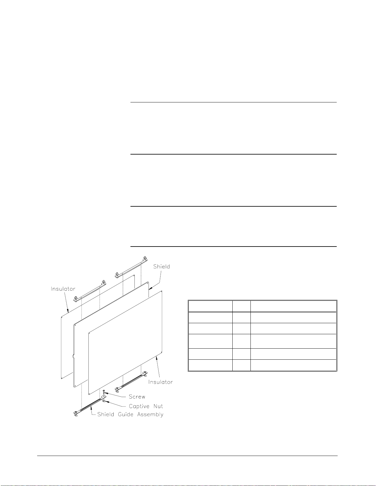
This guide sho ws how to install a n HP E14 09B C-Size VXIbus Chass is
Shield into an HP 75000 Series C Model HP E1401A Mainfra me. Figure 1
sho ws t he cha s s is s hield pa r ts a n d pa r t numb ers .
the hazards involved should install , remove, or co nfigu re the system.
Disconnect all power sources to the mainframe and to all installed
modules before beginning the installation.
and 10 require removal of a rail channel screw (see Step 4). If you later
remove a shield guide between any of these slots, replace this screw to
ensure RFI and airflow integrity of the mainframe.
If you want to install more than one shield, you should install all shield guides
at the same time.
HP E1409B Replaceable Parts
Part Number Qty. Description
E1409-00602 1 Chassis Shield Assemb ly
E1409-81202 4 Shield Guide Assembly
E1409-84101
0515-1108 8
0515-0122 8 Captive Nut, M2.4x0.45
Figure 1. HP E1409B Chassis Shield Kit
2
HP E1409B Installation Guide 5
Insulator
Screw - PHD M2.5x12mm
Page 6
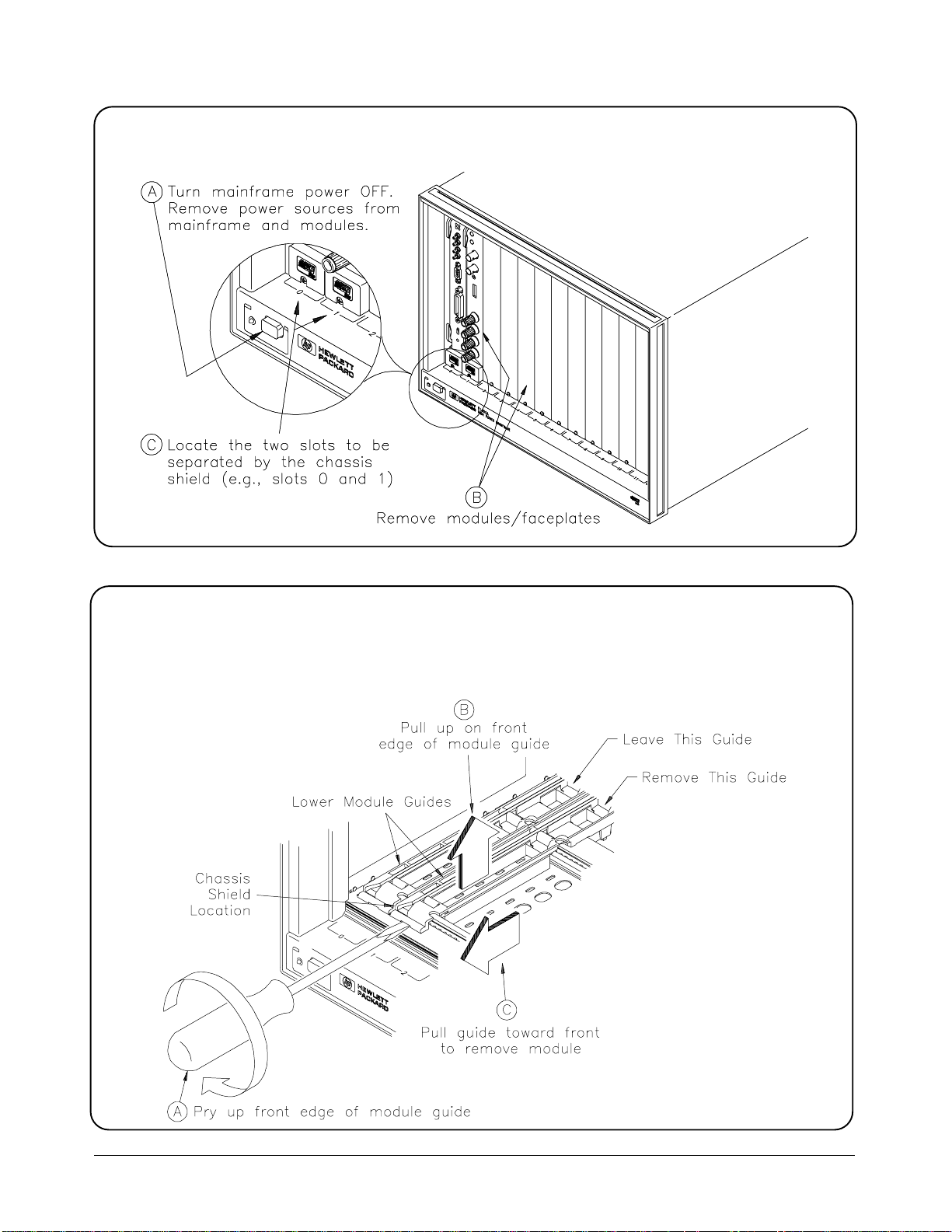
Step 1. Prepare the Mainfr am e
Step 1. Prepare the Mainfr am e
Step 2. Remove the Lower Module Guid e
Step 2. Remove the Lower Module Guid e
Remove the lowe r mod ule guide from the slot at the right of the chass is shield location . Do not
Remove the lowe r mod ule guide from the slot at the right of the chass is shield location . Do not
remove the module guide at the left of the chassis shield location. (This publication shows
remove the module guide at the left of the chassis shield location. (This publication shows
chassis shield installation between slots 0 and 1.)
chassis shield installation between slots 0 and 1.)
6 HP E1409B Installation Guide
Page 7
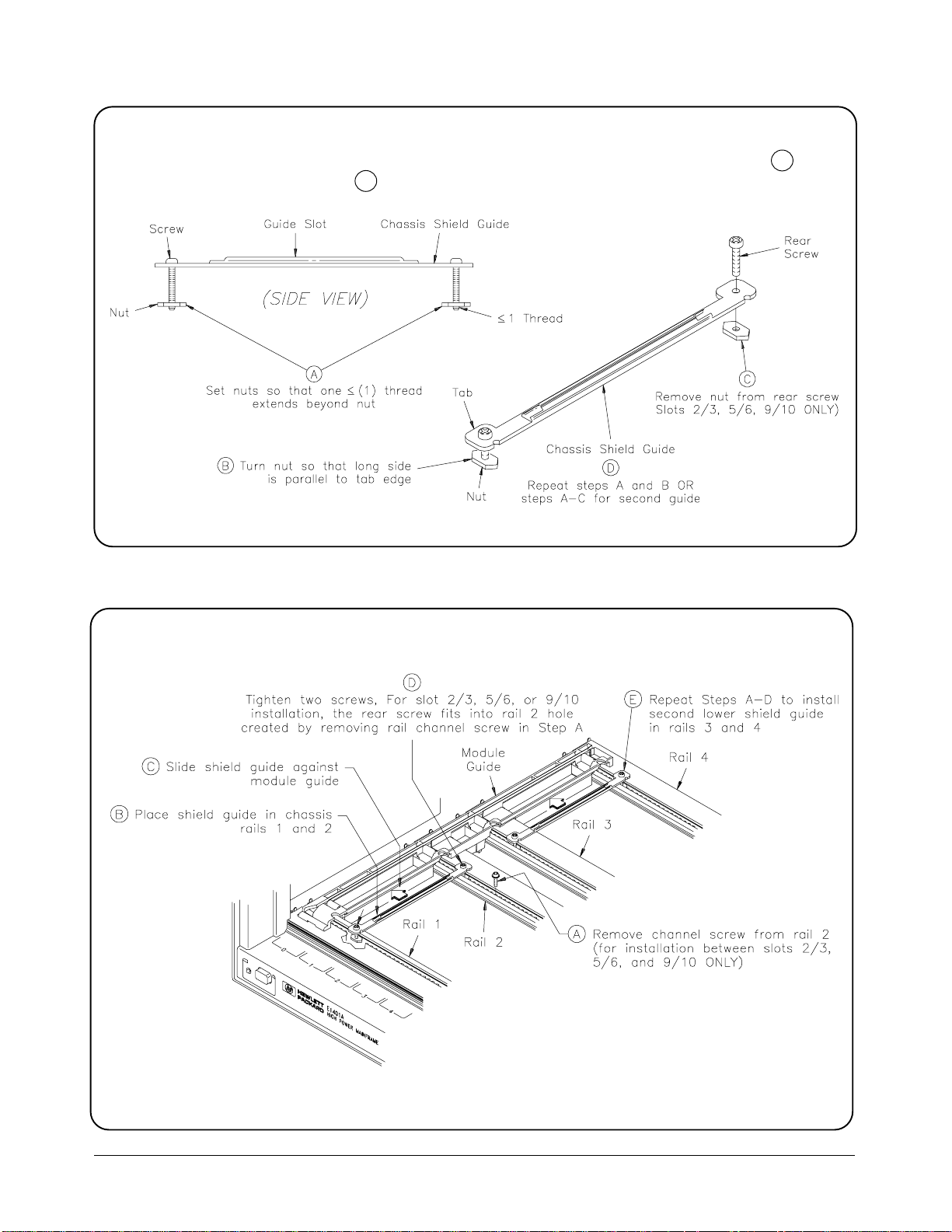
Step 3. Prepare Two (2) Lower Shi eld Gui des
If the chassis shield is to be installed between slots 2 and 3, 5 and 6, or 9 and 10, do C . For
installatio n in oth er slots, skip C . You will need to prepare TW O lowe r shield gu ide s.
Step 4. Install Two (2) Lower Shield Guides
HP E1409B Installation Guide 7
Page 8
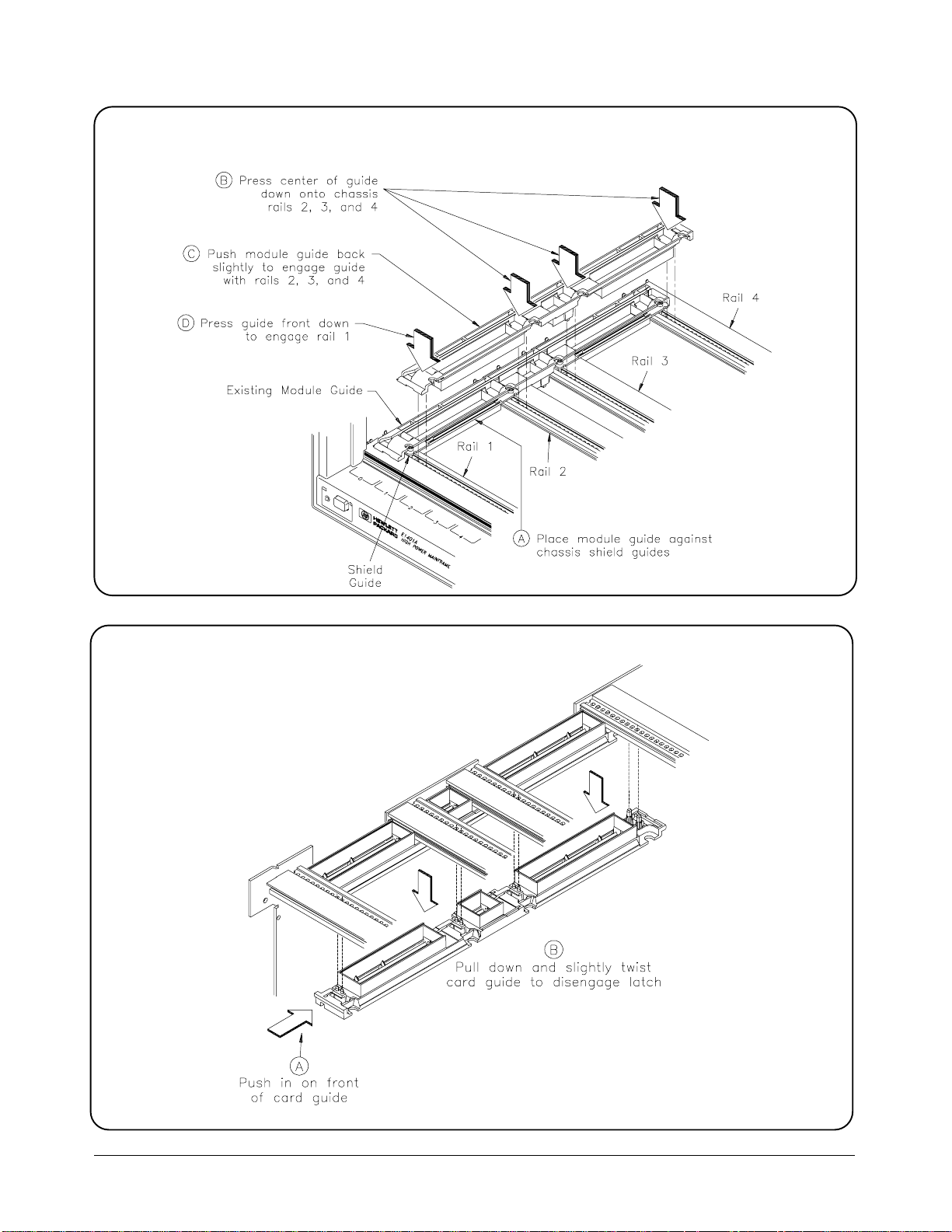
Step 5. Reinstall Lower Module Guide
Step 6. Remove the Upper Module Guide
8 HP E1409B Installation Guide
Page 9
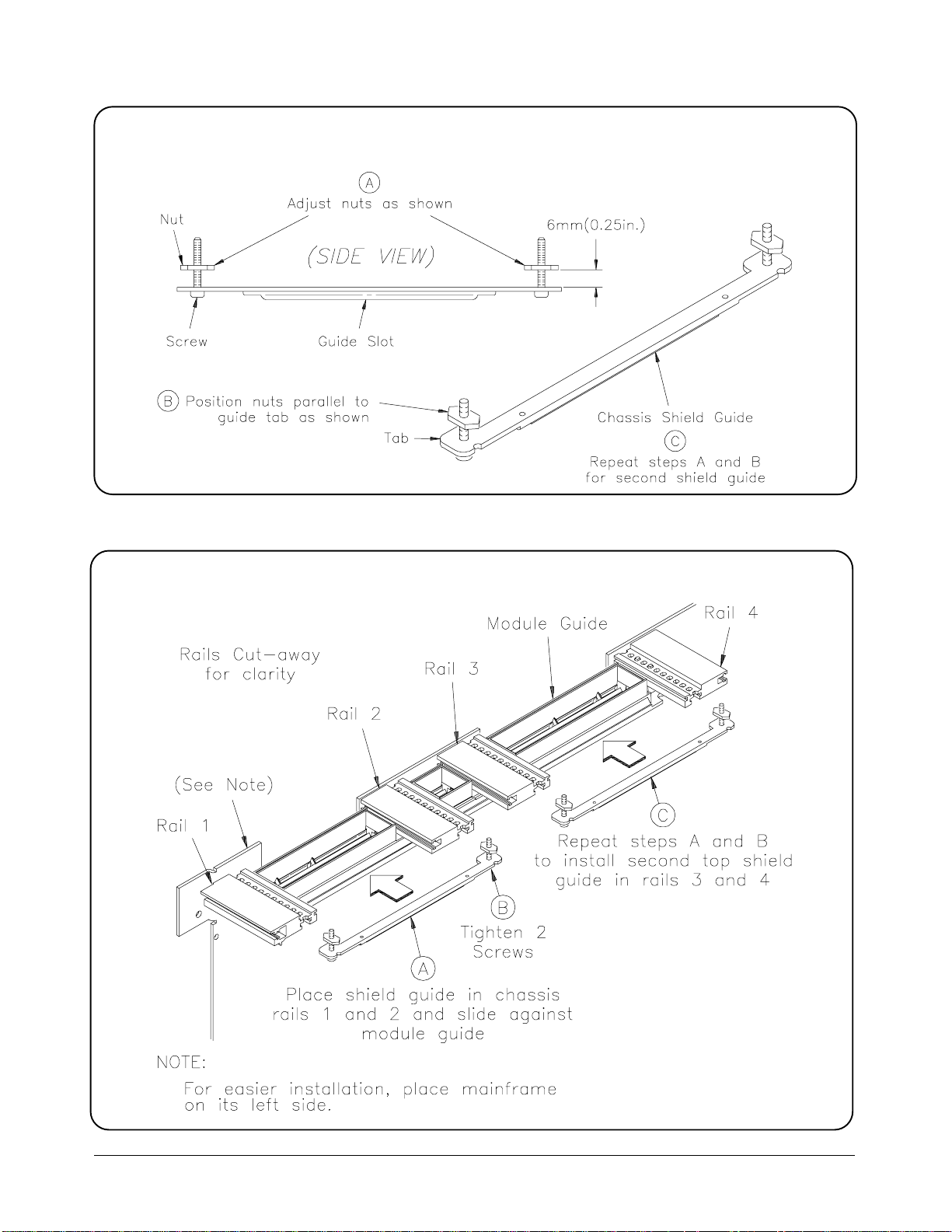
Step 7. Prepare Two (2) Upper Shield Gui des
Step 8. Install Two (2) Upper Shield Guides
HP E1409B Installation Guide 9
Page 10
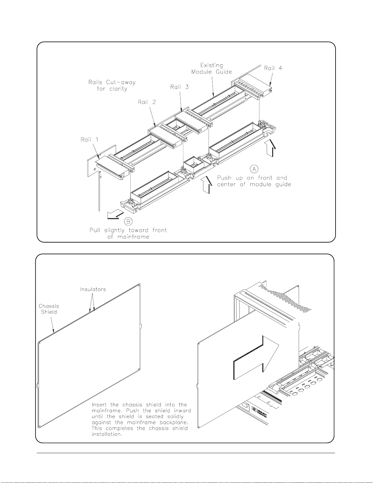
Step 9. Reinstall the Upper Module Guide
Step 10. Instal l the Chassi s Shie ld
10 HP E1409B Installation Guide
 Loading...