

Page 1

Contents
HP E1328A D/A Converter Module User’s Manual
Warranty . . . . . . . . . . . . . . . . . . . . . . . . . . . . . . . . . . . . . . . . . . 5
WARNINGS . . . . . . . . . . . . . . . . . . . . . . . . . . . . . . . . . . . . . . . . 6
Safety Symbols . . . . . . . . . . . . . . . . . . . . . . . . . . . . . . . . . . . . . . 6
Declaration of Conformity . . . . . . . . . . . . . . . . . . . . . . . . . . . . . . . . . 7
Reader Comment Sheet . . . . . . . . . . . . . . . . . . . . . . . . . . . . . . . . . . 9
Chapter 1. Getting Star ted with the HP E1 328A . . . . . . . . . . . . . . . . . . . . . . . 11
Using This Chapter . . . . . . . . . . . . . . . . . . . . . . . . . . . . . . . . . . . . 11
D/A Convert er Descr i pti on . . . . . . . . . . . . . . . . . . . . . . . . . . . . . . . . 11
General Description . . . . . . . . . . . . . . . . . . . . . . . . . . . . . . . . . . 11
Instrument Definition . . . . . . . . . . . . . . . . . . . . . . . . . . . . . . . . . . . 12
Programmi ng th e D/A Converter . . . . . . . . . . . . . . . . . . . . . . . . . . . . . 13
Selecting SCPI Commands . . . . . . . . . . . . . . . . . . . . . . . . . . . . . . 13
Chapter 2. Configuring the HP E1328A . . . . . . . . . . . . . . . . . . . . . . . . . . . . 15
Using This Chapter . . . . . . . . . . . . . . . . . . . . . . . . . . . . . . . . . . . . 15
Warnings and Cautions . . . . . . . . . . . . . . . . . . . . . . . . . . . . . . . . . . 15
Setting the Logical Address Switch . . . . . . . . . . . . . . . . . . . . . . . . . . . . 16
Selecting Voltage or Cur ren t Out put . . . . . . . . . . . . . . . . . . . . . . . . . . . 17
Connecting Field Wiring . . . . . . . . . . . . . . . . . . . . . . . . . . . . . . . . . 18
Wiring Guideli nes . . . . . . . . . . . . . . . . . . . . . . . . . . . . . . . . . . 18
Chapter 3. Using the HP E1328A . . . . . . . . . . . . . . . . . . . . . . . . . . . . . . . . 19
Using This Chapter . . . . . . . . . . . . . . . . . . . . . . . . . . . . . . . . . . . . 19
D/A Convert er Com ma nds . . . . . . . . . . . . . . . . . . . . . . . . . . . . . . . . 19
Reset Conditions . . . . . . . . . . . . . . . . . . . . . . . . . . . . . . . . . . . . . . 19
Electron ic Voltage Adjustment . . . . . . . . . . . . . . . . . . . . . . . . . . . . . . 20
Outputting Voltage . . . . . . . . . . . . . . . . . . . . . . . . . . . . . . . . . . . . 23
Electronic Current Adjustment . . . . . . . . . . . . . . . . . . . . . . . . . . . . . . 26
Outputting Current . . . . . . . . . . . . . . . . . . . . . . . . . . . . . . . . . . . . . 29
Chapter 4. Understanding the HP E1328 A . . . . . . . . . . . . . . . . . . . . . . . . . . . 31
Using This Chapter . . . . . . . . . . . . . . . . . . . . . . . . . . . . . . . . . . . . 31
Commands for D/A Conv erter Operation . . . . . . . . . . . . . . . . . . . . . . . . . 31
Voltage Output . . . . . . . . . . . . . . . . . . . . . . . . . . . . . . . . . . . . . . . 32
Remote Sense . . . . . . . . . . . . . . . . . . . . . . . . . . . . . . . . . . . . . . . 33
Maximum Lead Resistance . . . . . . . . . . . . . . . . . . . . . . . . . . . . . . 33
Operation with Fixed Voltage Sources i n Series . . . . . . . . . . . . . . . . . . . 34
Adjustment Under A ctual Lead and L oad Condi tions . . . . . . . . . . . . . . . . 34
Current Output . . . . . . . . . . . . . . . . . . . . . . . . . . . . . . . . . . . . . . . 36
Querying the D/ A Converter . . . . . . . . . . . . . . . . . . . . . . . . . . . . . . . 37
HP E1328A D/A Converte r Module User’s Manual Contents 1
Page 2

Chapter 5. HP E1328A Command Reference . . . . . . . . . . . . . . . . . . . . . . . . . 39
Using This Chapter . . . . . . . . . . . . . . . . . . . . . . . . . . . . . . . . . . . . 39
Command Types . . . . . . . . . . . . . . . . . . . . . . . . . . . . . . . . . . . . . . 39
Common Command Format . . . . . . . . . . . . . . . . . . . . . . . . . . . . . 39
SCPI Command F ormat . . . . . . . . . . . . . . . . . . . . . . . . . . . . . . . 39
Linking Commands . . . . . . . . . . . . . . . . . . . . . . . . . . . . . . . . . . 41
SCPI Command Reference . . . . . . . . . . . . . . . . . . . . . . . . . . . . . . . . 41
CALibration . . . . . . . . . . . . . . . . . . . . . . . . . . . . . . . . . . . . . . . . 42
CALibration
CALibration
CALibration
CALibration
DISPlay . . . . . . . . . . . . . . . . . . . . . . . . . . . . . . . . . . . . . . . . . . 45
DISPlay:MONitor:C HANn el . . . . . . . . . . . . . . . . . . . . . . . . . . . . . 45
DISPlay:MONitor:C HANn el? . . . . . . . . . . . . . . . . . . . . . . . . . . . . 46
DISPlay:MONit or[:STATe] . . . . . . . . . . . . . . . . . . . . . . . . . . . . . 46
DISPlay:MONit or:STRi ng ? . . . . . . . . . . . . . . . . . . . . . . . . . . . . . 46
[SOURce:] . . . . . . . . . . . . . . . . . . . . . . . . . . . . . . . . . . . . . . . . . 47
[SOURce:]CURRent
[SOURce:]CURRent
[SOURce:]FUNCtion
[SOURce:]VOLTage
[SOURce:]VOLTage
SYSTem . . . . . . . . . . . . . . . . . . . . . . . . . . . . . . . . . . . . . . . . . . 49
SYSTem:ER Ror? . . . . . . . . . . . . . . . . . . . . . . . . . . . . . . . . . . . 49
IEEE-488. 2 Common Command Quick Referen ce . . . . . . . . . . . . . . . . . . . . 50
HP E1328A Comma nd Quick Reference . . . . . . . . . . . . . . . . . . . . . . . . . 51
n:CURRent . . . . . . . . . . . . . . . . . . . . . . . . . . . . . . . 42
n:STATe . . . . . . . . . . . . . . . . . . . . . . . . . . . . . . . . 43
n:STATe? . . . . . . . . . . . . . . . . . . . . . . . . . . . . . . . . 43
n:VOLTage . . . . . . . . . . . . . . . . . . . . . . . . . . . . . . . 44
n . . . . . . . . . . . . . . . . . . . . . . . . . . . . . . . . 47
n? . . . . . . . . . . . . . . . . . . . . . . . . . . . . . . . . 47
n? . . . . . . . . . . . . . . . . . . . . . . . . . . . . . . . 48
n . . . . . . . . . . . . . . . . . . . . . . . . . . . . . . . . 48
n? . . . . . . . . . . . . . . . . . . . . . . . . . . . . . . . . 48
Appendix A. HP E1328A Speci fications . . . . . . . . . . . . . . . . . . . . . . . . . . . . 53
Appendix B. HP E1328A Register-Based Progr amming . . . . . . . . . . . . . . . . . . . 55
Using This Appen dix . . . . . . . . . . . . . . . . . . . . . . . . . . . . . . . . . . . 55
Address ing the R egisters . . . . . . . . . . . . . . . . . . . . . . . . . . . . . . . . . 55
The Base Addres s . . . . . . . . . . . . . . . . . . . . . . . . . . . . . . . . . . . 56
Register Offset . . . . . . . . . . . . . . . . . . . . . . . . . . . . . . . . . . . . 58
Register Definition s . . . . . . . . . . . . . . . . . . . . . . . . . . . . . . . . . . . . 59
Register Descriptions . . . . . . . . . . . . . . . . . . . . . . . . . . . . . . . . . . . 60
Manufacturer ID Register . . . . . . . . . . . . . . . . . . . . . . . . . . . . . . . 60
Device Type Register . . . . . . . . . . . . . . . . . . . . . . . . . . . . . . . . . 60
Status/C ont rol Register . . . . . . . . . . . . . . . . . . . . . . . . . . . . . . . . 60
Channel M ode Regist er s . . . . . . . . . . . . . . . . . . . . . . . . . . . . . . . 63
Channel Outp ut Regi sters . . . . . . . . . . . . . . . . . . . . . . . . . . . . . . . 63
Command and Parameter Registers . . . . . . . . . . . . . . . . . . . . . . . . . 64
A Register- Based Algorithm . . . . . . . . . . . . . . . . . . . . . . . . . . . . . . . 71
Programming Examples . . . . . . . . . . . . . . . . . . . . . . . . . . . . . . . . . . 72
System Configuration . . . . . . . . . . . . . . . . . . . . . . . . . . . . . . . . . 72
Resetting the Module . . . . . . . . . . . . . . . . . . . . . . . . . . . . . . . . . 72
2 HP E1328A D/A Converter Module User’s Manual Contents
Page 3

Reading the ID, D evice Typ e, a nd Status Registers . . . . . . . . . . . . . . . . . . . . 74
Outputting a Voltage or Current . . . . . . . . . . . . . . . . . . . . . . . . . . . 76
Using an Embedded
HP RADI-EPC7 Comput er . . . . . . . . . . . . . . . . . . . . . . . . . . . . . 79
Appendix C. HP E1328A Error M e ssages . . . . . . . . . . . . . . . . . . . . . . . . . . . 83
Index . . . . . . . . . . . . . . . . . . . . . . . . . . . . . . . . . . . . . . . . . . . . . . . . 85
HP E1328A D/A Converte r Module User’s Manual Contents 3
Page 4

4 HP E1328A D/A Converter Module User’s Manual Contents
Page 5

Certification
Hewlett-Packard C ompa n y certifi es that this produ ct met its publi sh ed speci fica tions a t the time of shipme nt from the factor y. HewlettPackard furth er cert ifi es that its cali brat ion mea sureme nt s are tracea bl e to the Unit ed Sta tes Na tion al Inst itute of Stan dards and Technology (formerly National Bureau of Standards), to the extent allowed by that organization’s calibration facility, and to the calibration
facilities of other International Standards Organization members.
Warranty
This Hewlet t-Pa ck ar d product is warr ante d agai nst de fect s in mate rials and w orkmansh ip for a period of three yea rs from date of shipment. Duration and conditi ons of warranty for this product may be superse ded when the pr oduct is integrate d into (become s a part of)
other HP products. During the wa rranty period, Hewlett-Pack ar d Company will, at its option, either repair or replace pr oducts which
prove to be defective.
For warrant y se r vice or repair, this pr oduct must be returned to a service facility design at ed by Hewlett-P ackard (HP). Buyer shall prepay shippin g charges to HP and HP shall pa y shipping charges to return the product to B uyer. However, Buyer shall pay all shi pping
charges, dutie s, an d taxe s for products ret urned to HP from an other cou ntry.
HP warrants tha t its softwar e and fir mwar e designa t ed b y HP for use with a product will exe cu te its pr ogrammin g instru cti ons wh en
properly installe d on that product . HP does not warrant that t he operat ion of the product, or software, or firmware wi ll be uninterrupted
or er ro r f r ee.
Limitation Of Warranty
The foreg oin g warranty shall not appl y t o defects resul ting from i mproper or inade quate mainte nance by Buyer, Buyer-supplied products or interfacing, unauthori ze d m odificati on or misus e, opera tion outside of the environmental specificat ions for the product, or improper site prep arat i on or maint ena nce.
The design an d imp le mentation of any circuit on this product is the sole responsibility of th e Buyer. HP does not war rant th e Buyer’s
circuitr y or malfunction s of HP products that result from the Bu yer’s circuit r y. In addition, HP does not warrant an y damage tha t occurs as a result o f the Buyer’s circuit or an y defects th at re sult from Buyer-supplied products.
NO OTHER WARRANTY IS EXPRESSED OR IMPLIED. HP SPECIFICALLY DISCLAIMS THE IMPLIED W ARRANT IES OF
MERCHANTABILITY AND FITNESS FOR A PARTICULAR PURPOSE.
Exclusive Remedie s
THE REMED IES PROVIDED HEREIN ARE BUYER’S SOLE AND EXCLUSIVE REMEDIES. HP SHALL NOT BE LIABLE
FOR ANY DIRECT, INDIRECT, SPECIAL, INCIDENTAL, OR CONSEQUENTIAL DAMAGES, WHETHER B ASED ON CONTRACT, TORT, OR ANY OTHER LEGAL THEORY.
Notice
The information contained in this document is subject to change without notice. HEWLETT-PACKARD (HP) MAKES NO WARRANTY OF ANY KIND W ITH REGARD TO THIS MATERIAL, INCLUDING, BUT NOT LIMITED TO, THE IMPLIED WARRANTIES OF MERCHANTABILITY AND FITNESS FOR A PARTICULAR PURPOSE. HP shall not be liable for errors contained
herein or for incidental or consequential damages in connection with the furnishing, performance or use of this material. This document c ontai ns proprieta ry informati on which is protected by cop yri ght. All rights ar e reserved. No part of this d ocument may be photocopied, reproduced, or tran slate d to anothe r langua ge wit h out the prior written c onsent of Hewlett -P ackar d Company. HP assumes no
responsibility for the use or reliability of its software on equipment that is not furnished by HP.
U.S. Government Restricted Rights
The Software and Do cumentat ion ha ve bee n develope d entir ely at privat e expe nse . The y are delivered and lice nsed as "c omme rcia l
computer software" as defin ed in DF ARS 252.227-701 3 (October 1988 ), DF ARS 252.211.701 5 (May 1991) or DFARS 252.227-7014
(June 1995), as a "comme rcia l item" as defined in F AR 2.101(a ), or as "Restrict e d comp uter software " as define d in FAR 52.227-19
(June 1987) (or any equival en t agen cy re gula tion or c ontract cla use ), whi ch ever is appl ica bl e. You have only those right s provided for
such Software and D ocum ent at ion by the applicable FA R or DFARS clause or the HP standar d so ftware agreement for the pr oduct involved.
HP E1328A User’s Manual
Copyright © 1996 He wle tt-Pa cka rd Company. All Right s Reser ve d.
Edition 5
HP E1328A User’s Man ual 5
Page 6
Documentatio n History
All Editions and Updates of this manual and their creation date are listed below. The first Edition of the manual is Edition 1. The Edition number increment s by 1 whenever the manua l is revised . Updates , which are issued betw een Edi ti ons, c ontain repla ce ment pa ges
to correct or add additional information to the current Edi tion of the manua l. Whene ver a new Edition is creat ed, it will c ontain all of
the Update information for the pre vious Edit ion. Each new Ed ition or Update also include s a revised c op y of this documentation hi story page.
Edition 1 . . . . . . . . . . . . . . . . . . . . . . . . . . . . . . . . . . . . . . . . . . . Septe mber 1989
Edition 2 . . . . . . . . . . . . . . . . . . . . . . . . . . . . . . . . . . . . . . . . . . . . . . . . May 1992
Edition 3 . . . . . . . . . . . . . . . . . . . . . . . . . . . . . . . . . . . . . . . . . . . . February 1994
Edition 4 . . . . . . . . . . . . . . . . . . . . . . . . . . . . . . . . . . . . . . . . . . . . . . . April 1995
Edition 5 . . . . . . . . . . . . . . . . . . . . . . . . . . . . . . . . . . . . . . . . . . . November 1996
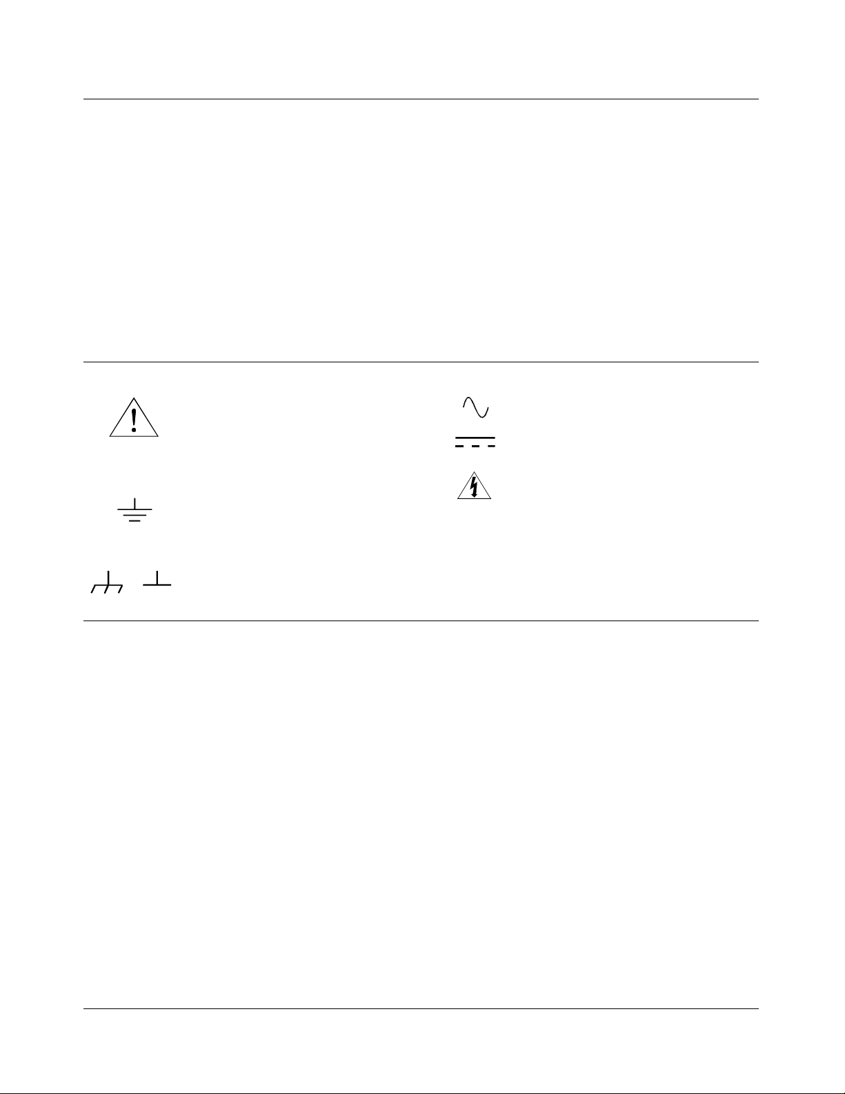
Safety Symbols
Instruction manual symbol affixed to product. Indicat es that the user must re fe r t o the
manual for specific WARNING or CAUTION information to avoid personal injury
or damage to the product.
Indicates the field wiring terminal that must
be connected to earth ground before operating the equipment—protects against electrical shock in case of fault.
Frame or chassis ground termi nal — t ypi-
or
cally connects to the equipment’s metal
frame.
WARNING
CAUTION
Alternating current (AC).
Direct curren t (DC).
Indicate s ha za rdous voltag e s.
Calls at te nt i on t o a pr ocedure, practi ce, or
condition that could cause bodily injury or
death.
Calls at te nt i on t o a pr ocedure, practi ce, or condition that could possibly cause damage to
equipme nt or perma nen t los s of data.
WARNINGS
The following ge ner al safet y prec aut ions mu s t be observed du ri ng al l phas es of oper ation, service, an d repai r of this prod uct .
Failure to comply with these prec aut ions or with specific war nings elsewhe re in this manual violates safety stand ard s of design ,
manufacture, and intended use of the produc t. H ewl ett-Packard Company assumes no liability for the customer’s fai lu re to
comply with these requirements.
Ground the equipment: For Safety Cl as s 1 equipmen t (equ ipment ha vin g a protective ea rth ter mi nal) , an unint erru ptib le sa fety earth
ground must be provide d from the ma in s power sour ce to the produ ct input wi rin g termi nals or suppli ed power cable .
DO NOT operate the produc t in an explosive at mospher e or in the presen ce of flammable gases or fumes.
For continued protect ion a gainst fire, repl ace the li ne fuse(s) only with fuse(s) of the same voltage and curre nt rating and type .
DO NOT use repaired fuses or short-circui ted fuse holders.
Keep away from live circuits: Operatin g personnel must not remove equipment covers or shields. Procedures involving the removal
of covers or shields are for use by service-trained pers onn el onl y. Unde r ce rtain conditions, dangerous voltages m ay exist even with th e
equipment switched off. To avoid dangerous ele ctrical shock , DO NOT perf orm procedures involving cover or shield removal unless
you are qualified to do so.
DO NOT operate damaged equipment: Whenever it is possibl e that the safety protection feat ur es built into this pr oduct have been im paired, either t hr ough physical dam a ge, excessive moisture, or an y ot her re as on, REMOVE POWER and do not use the pr oduct until
safe operation can be verified by service-trained personnel. If necessary, return the produ ct to a Hewlett -P ackar d Sales a nd Ser vice Office for service and repair to ensure that safety features are maintaine d.
DO NOT service or adjust alon e: Do not attempt internal service or adjustment unless another person, capable of rendering first aid
and resuscitation, is present.
DO NOT substitute par ts or modify equipm ent: Because of the danger of introducing additional hazar ds, do not install substitut e
parts or perform any unauth orized modifica tion to the product. Ret urn the produ ct to a Hewlett -Packar d Sa les and Ser vice O ffice for
service and repair to ensure that safety features are maintained.
6 HP E1328A User’s Manual
Page 7
Declaration of Conformity
according to ISO/IEC Guide 22 and EN 45014
Manufacturer’s Name: Hewlett-Pa ckar d C ompany
Loveland Manufacturing Center
Manufact ure r’s Addre s s: 815 14th Street S.W.
Loveland, Colorado 80537
declares, that the product:
Product Name: 4-Chan nel D/A Con ver ter Module
Model Number : HP E1 328A
Produc t Opt ion s: All
conforms to the following Pr od uct Spe cifi cati ons :
Safety: IEC 348:1978 /HD 401 S1:1 981
CSA 556B
UL 1244
EMC: CISPR 11:1990/EN55011 (1991): Group 1 Class A
EN50082-1: 1992
IEC 801-2:1991: 4 kVCD, 8 kVAD
IEC 801-3:1 984: 3 V/m
IEC 801-4:1988: 1 kV P ower Line , .5 kV Signal Lin es
Supplementary Information: The product herewith c omplies wit h th e requirements of the Low Voltage
Directive 73/23/EEC and the EMC Directive 89/336/ EEC (inclu sive 93/68/E EC) and carr ies the "CE" mark ing
according ly.
Tested in a typical HP B-Size VXI Ma infr a me.
Safety qualification perfor m ed May, 1989.
Septemb e r 16, 199 6 Jim White , QA Manager
European c ontact : Your loca l He wlett-Pa cka rd Sa les and Ser vi ce O ffic e or Hewlett- Packa rd GmbH,
Department HQ- TRE, Herrenberger Straße 130, D-71034 Böblingen , Germany (FAX +49-7031-14-3143).
HP E1328A User’s Man ual 7
Page 8

Notes
8 HP E1328A User’s Manual
Page 9
Please fold and tape for mailing
Reader Comment Sheet
HP E1328A User’s Manual
Editio n 5
You can help us improve our manual s b y sharing your commen ts and sug gesti ons. In apprec iat i on of your time, we will
enter yo u in a quarterly drawing for a Hewle tt -Pac kar d Palmt op Per s onal C omputer (U.S. government employees
cannot participate in the drawing).
Your Name
C ompany Name
Job Title
Address
City, State/Province
Country
Zip/Postal Code
Telephone Number with Area Code
Please list the s ystem c ontroller, opera ting system, program ming lan gua ge, and plug -in modules you are usi ng.
fold here
BUSINESS REPLY MAIL
FIRST CLASS PERMIT NO. 37 LOVELAND, CO
HEWLETT-PACKARD COMPANY
cut along this line
Measurement Systems Division
Learning Products Department
P.O.Box 301
Loveland, CO 80539-9984
NO POSTAGE
NECESSARY
IF MAILED
IN THE
UNITED STATES
fold here
Please pencil- in on e circle for each stat ement below: Disagree Agree
• The documentation is well organized. OOOOO
• I nstructions are easy to understand. OOOOO
• The documentation is clearly written. OOOOO
• Examples are clear and useful. OOOOO
• Illustrations are clear and helpful. OOOOO
• The documentation meets my overall expectations. OOOOO
Please write any comments or suggestions below--be specific.
Page 10

10 HP E1328A User’s Manual
Page 11
Getting Started with the HP E1328A
Using This Chapter
This chapter describes the HP E1328A 4-Channel D/A Converter module,
and contains inf ormat ion on how to program it using S CP I (St a n dard
Commands for Programmable Instruments) commands. This chapter
contains the following sections:
• D/A Converter Description . . . . . . . . . . . . . . . . . . . . . . . . . . Page 11
• Inst rumen t Definiti on. . . . . . . . . . . . . . . . . . . . . . . . . . . . . . . Page 12
• Progra mming the D/A Converter. . . . . . . . . . . . . . . . . . . . . . Page 1 3
D/A Converter Description
The HP E1328A 4-Channel D/A Converter provides four independent,
16-bit isolated digital-to-analog channels configurable for either DC voltage
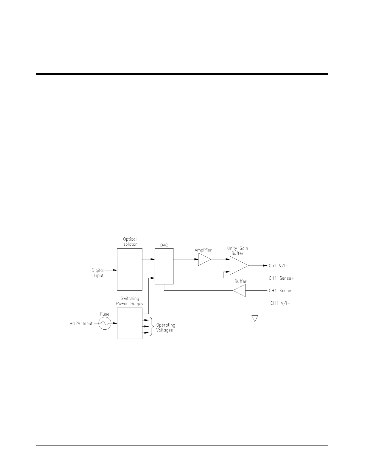
or DC current output. Figure 1 -1 shows a block diagram for one of the four
HP E1328A channels. All four channels have the same block diagram.
Chapter 1
Figure 1-1. D/A Converter Block Diagra m
General Description Each of the four channels can be programmed to output voltage or current in
one of the two operat ing modes.
– Calibrated mode: output voltage range is ±10.922 Vdc and
output current range is ±21. 84 m Adc .
– Non-calibrated mode: output range is typically ±12 Vdc
and ±24 mAdc.
Chapter 1 Getting Started with the HP E1328A 11
Page 12

In the calibrated mode, output accuracy is dependent on the date of the last
electronic ad justme nt perf ormed ( s ee Appen dix A). This accuracy is
maintained by use of stored adjustment constants in memory. Each channel
has ind epen dent adjustment constants f or b oth volt age and current, whic h
are updated by performing th e appropriate electronic a d justment procedu re
(see Chapter 3).
The electronic adjustment procedures used to update the channel’s stored
voltage and/or current adjustment constant in memory requires only a
1
multime t er (5
a system multimeter is used, the electro nic adjust ment procedures can also
be automated.
The four channels are electrically isolated from each other, and from chassis
ground. This allows the usable output range (voltage and/or current) to be
expanded by linking multiple c hannels. For e xam ple, the output voltage range
can be expanded to 48 Vdc by linking channels in series, and the output current
range can be expanded to 96 mAdc by linking chan nels in parall el.
Both voltage and current out puts on all channels are provided with output
short circuit protection. Additionally, each channel configured for
outputting voltage has no-fault r emote-sensing cap ab ilit y to ensure accurate
voltages at the load. If o ne of the sense leads become disconnected, the
D/A Converter will automatically revert to local sensing.
⁄2-digit, 0.015% of re a ding + 1 mV accuracy ) to c omp lete. If
The AC FAIL line (from the mainframe) is constantly monitored by the
D/A Converter. If power fails, the D/A Converter channels are shut down
to conserve power and provid e great er hold-up time for the mainframe
power supp lie s.
Instrument Definition
HP plug-in modules installed in an HP mainframe are treated as
independent instruments, each having a unique secondary HP-IB address.
Each instrument is also assigned a dedicated error queue, input and output
buffers, status registers and, if applicable, dedicated mainframe memory
space for readi ngs or data. An instrument may be co mposed of a single
plug-in module (such as a counter) or multiple plug-in modules (for a
switchb ox or scanning voltme ter instrument).
12 Getting Started with the HP E1328A Chapter 1
Page 13

Programming the D/A Converter
To program the D/A Converter using Standard Commands for Programmable
Instruments (SCPI), you must select the controller language, interface address,
and SCPI commands to be used. See Installing the HP E1300A/E1301A
Mainframe and Plug-In Modules Configuration Guide for interface addressing
and controller language information.
Note This discussion applies to SCPI programming. See Appendix B for details
on register-based programming.
Selecting SCPI
Commands
Note Implied commands are those which appear in square brackets ([ ]) in the
A SCPI command consists of a keyword, such as the source command
[SOURce:]V OL Ta gen <level>. n defines the channel to be configured
(for voltage in this case). Most keywords require that you specify th e channel
(1, 2, 3, or 4) you want to act on. If no channel is specified, the default is
chan nel 1.
Some keywords m ust be follo wed by a value to set a parameter to a specif ic
value (for example, voltage level, [SOURce:]VOLTage1 10.00000).
10.00000" outputs +10.00000 Vdc on channel 1 if prop erly conf igured for
"
voltage. Additionally, some keywords must be followed by a value to set a
parameter to a specific
1" sets the D/A Converter c hannel 1 mo de to ON (calibration).
The "
command syntax. The brackets are not part of the command and are not
sent to the instru ment.
not required. See page 40 for more information about implied commands.
state (for example, calibration on/off CAL:STAT 1).
[SOURce:] is an implied comma nd a nd, therefore, is
Chapter 1 Getting Started with the HP E1328A 13
Page 14

Notes
14 Getting Started with the HP E1328A Chapter 1
Page 15

Configuring the HP E1328A
Using This Chapter
This chapter shows how to connect external wiring to the 4-Channel D/A
Converter module inputs, and how to configure the module for voltage and
current output. This chapter contains the following sections:
• Warnings a nd C aut ions . . . . . . . . . . . . . . . . . . . . . . . . . . . . . Page 15
• Setting the Logical Address Switch. . . . . . . . . . . . . . . . . . . . Page 16
• Selecting Voltage or Cur re nt Output. . . . . . . . . . . . . . . . . . . Page 17
• Connecting Field (user) Wiring . . . . . . . . . . . . . . . . . . . . . . . Page 18
Warnings and Cautions
WARNING SHOCK HAZARD. Only service-trained personnel who are aware of
the hazards involved should install, remove, or configure the D/A
Converter module. Before you remove any i nstalled mo dule,
disconnect AC power from the mainframe and field wiring.
Chapter 2
CAUTION MAXIMU M VO LTA GE . The maximum voltage that may be applied
between any two terminals within the same channel is 15 Vdc. Do not apply
voltage between any pair of terminals if the D/A Converter is turned off.
STATIC ELECTRICITY. Static electricity is a major cause of component
failure. To prevent damage to the electrical components in the D/A
Converter module, observe anti-static techniques whenever removin g a
module from the mainframe or whenever working on a module.
Chapter 2 Configuring the HP E1328A 15
Page 16
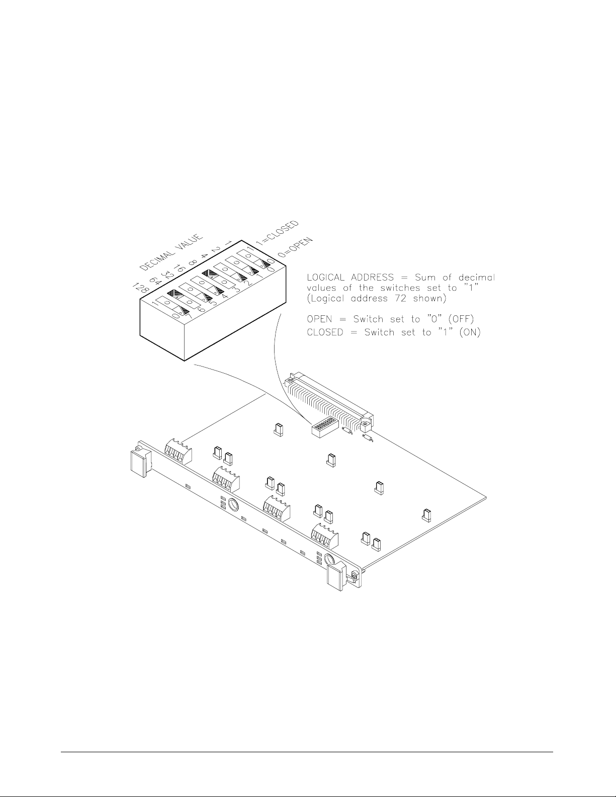
Setting the Logical Address Switch
The address switch (LADDR) factory setting is 72. You may have changed the
setting during module installation. Valid address values are from 0 to 255. If
the D/A Converter module is used in a HP E1300/E1301 Mainframe, refer to
Installing the HP E1300A/E1301A Mainframe and Plug-In Modules
Configuration Guide for addressing information. Oth erwise, use Figure 2-1 to
change the setting.
Figure 2-1. Locate and Set the Logical Address Swi tch
16 Configuring the HP E1328A Chapter 2
Page 17
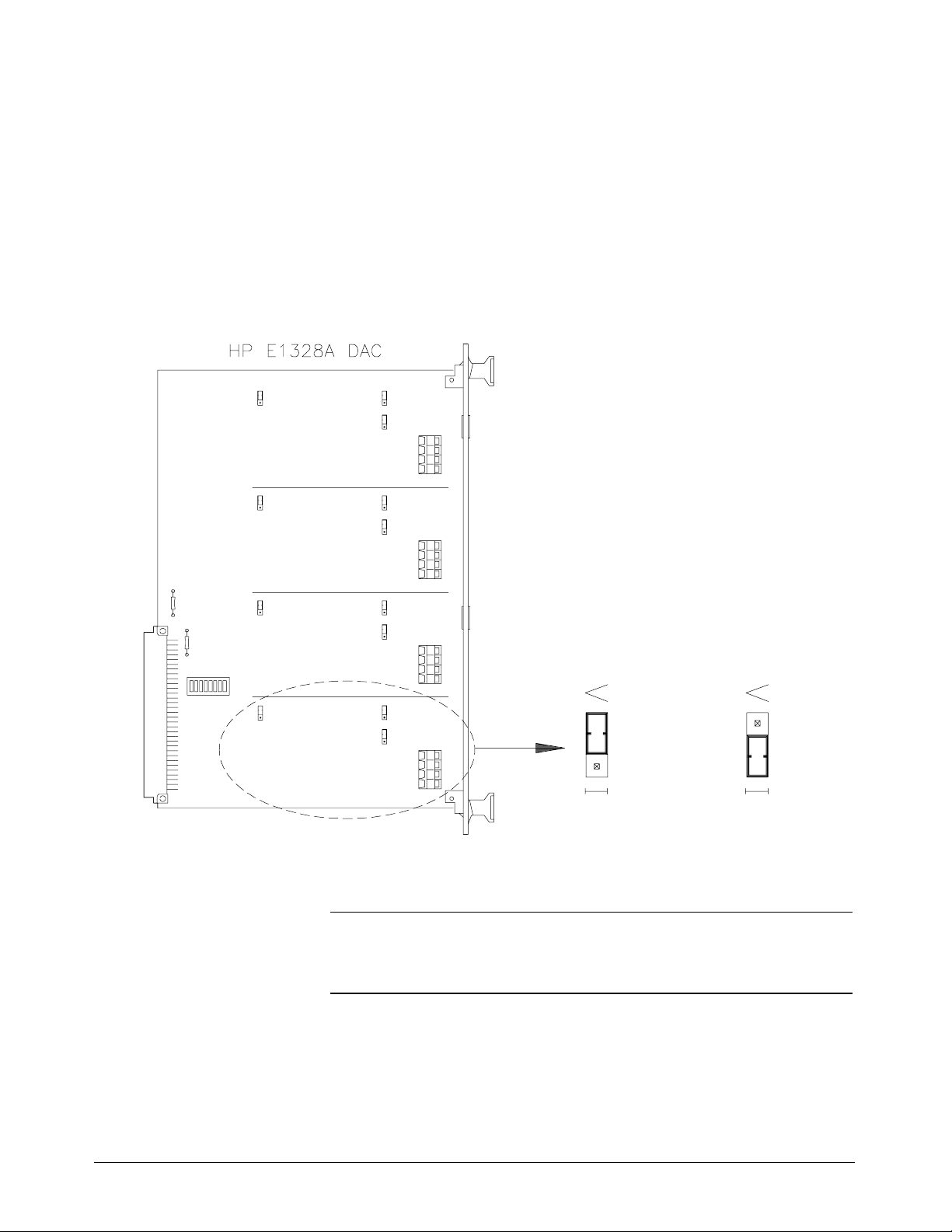
Selecting Voltage or Current Output
Each of the four D/ A Co nverter channels is capable of providing either a
voltage or current output. Voltage or curre nt can b e s elec ted for each
channel independently. Figure 2-2 shows the jumper location for each
channel and highlights the jumpers for Channel 1. Figure 2-2 also s hows
the correct position for the desired output. Note that each channel contains
three jumpers, and that all jumpers for a channel must be changed to the
desired output.
Note:
All three jumpers must be c onfigured
to the same outp ut for any channel.
Set to Voltage
Figure 2-2. Voltage/Cu rren t Output Select ion
Set to Current
CAUTION Moving the V/I jumpers with power applied to the D/A Converter
could cause improper operation or damage.
Chapter 2 Configuring the HP E1328A 17
Page 18
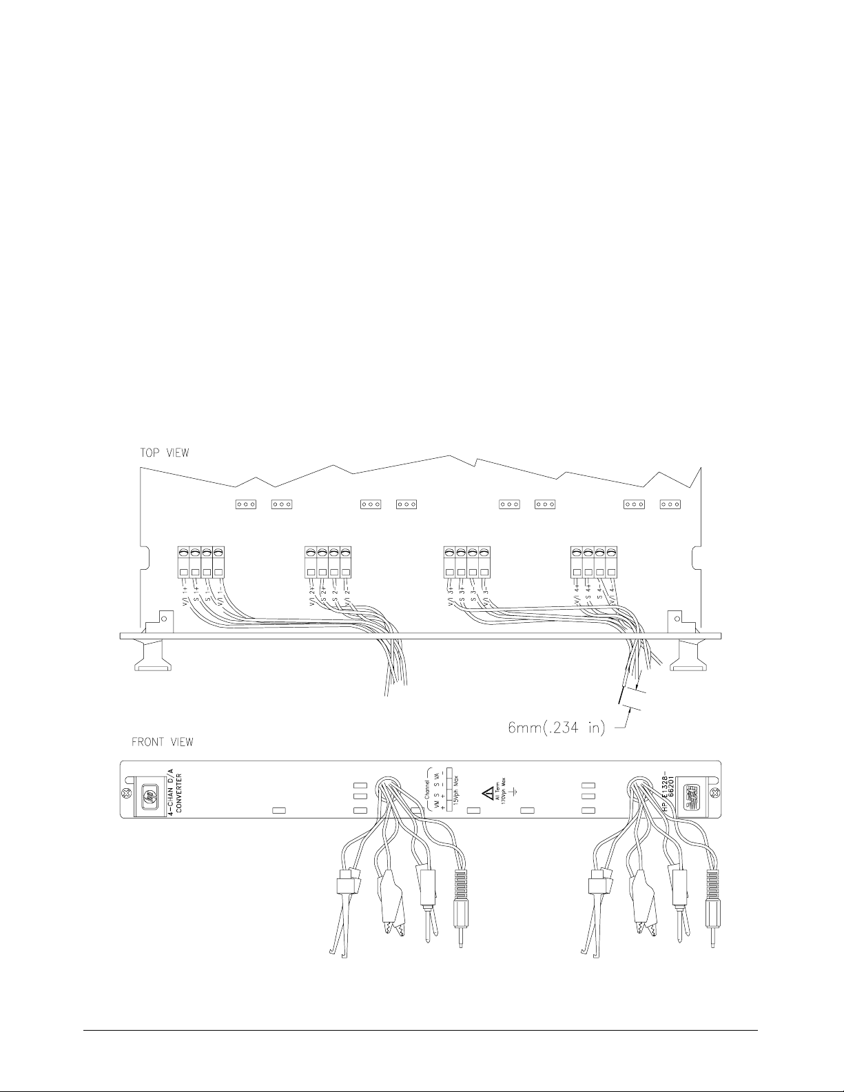
Connecting Field Wiring
Figure 2-3 shows the input terminals for the D/A Conv erter output and
sense terminals. Use the following guidelines for wire connections.
Wiring Guidelines • It is recommended that each channel wire be identified (color coded or
marked) as the connection is not visible when the D/A Converter
module is installed.
• Be sure that wires make good connections on the screw terminals.
• Maximum wire size is 16 AWG. Wire ends should be stripped 6 mm
(≈0.234 inch) and tinned to preve nt single strands from shorting
adjac ent ter minals .
• The other end may have any connection the user determines necessary.
• Do not conn ect th e channel’s SENSE terminals if they will not be
used (for examp le, c hannel is being configured for a curr e nt output,
or a voltage output without remote sensing).
Figure 2-3. D/A Converter Terminals
18 Configuring the HP E1328A Chapter 2
Page 19

Using This Chapter
This chapter uses typical examples to show how to use the 4-Channel D/A
Converter. Ref er to Chapt er 4, “Understanding the HP E1328A”, for more
information. This chapter contains the f ol lowing:
• D/ A Co nverter Commands . . . . . . . . . . . . . . . . . . . . . . . . . . Page 1 9
• Reset Conditions . . . . . . . . . . . . . . . . . . . . . . . . . . . . . . . . . . Page 19
• Electronic Voltage Adjustment . . . . . . . . . . . . . . . . . . . . . . . Page 20
• Outputting Voltage. . . . . . . . . . . . . . . . . . . . . . . . . . . . . . . . . Page 23
• Electronic Current Adjustment . . . . . . . . . . . . . . . . . . . . . . . Page 26
• Outputting Current. . . . . . . . . . . . . . . . . . . . . . . . . . . . . . . . . Page 29
D/A Converter Commands
Table 3-1. D/A Converter Commands Used in Chapter 3
Chapter 3
Using the HP E1328A
Command ** Description
CAL:CURRn z,z, z
CAL
n:STAT y
CAL:VOLT
[SOURce:]CURR
[SOURce:]VOLT
*RST Sets the hardware and software to a known state.
**
n = channel numb er, xxx = desired value, y = ON (1) or OFF (0), and z, z,z = measured minimum , default (0),
and maximum values. [SOURce:] is a command that is implied (not required), but if it is used, delete the brackets
and send as SOURce:.
n z,z, z
n xxx
n xxx
Used during the current electronic adjustment procedure to update a channel’s stored
adjustment constants in memory.
Selects calibrated (ON | 1) or non-calibrated mode (OFF | 0).
Used during the voltage electronic adjustment procedure to update a channel’s stored
adjustment constants in memory.
Causes the D/A Converter to output a s p ecific current . Chan nel must be configured f or current
output (refer to page 17). Rang e is dep endent on the mode selected.
Causes the D/A Conv erter to out put a specific voltage. Channel must be confi gured for voltag e
output (refer to page 17). Rang e is dep endent on the mode selected.
Reset Conditions
When the D/ A Converter is switched on or *RST (reset), all four channels
ar e set t o 0 V d c / 0 mAd c o u t put ( ±100 ms.) and th e calibra ted mode is
select ed for all channels. Ref er to Chapter 4 for more infor mat ion.
Chapter 3 Using the HP E1328A 19
Page 20

Electronic Voltage Adjustment
The electronic voltage adjustment is used to update the stored voltage
constants f or each channel , an d should be performed :
– on initial set-up;
– periodically (24 hours or 90 days) to maintain desired output
accuracy (see Appendix A);
– when a ±5°C change in temperature from last adjustment performed
has occurred;
– when the type of load is changed;
– or anytime accuracy is in doubt.
The adjustment procedure is performed for each channel as follows:
1. Configure the desired channel(s) for voltage output (see page 17).
2. Connect the load to the desired D/A Converter channel. Connect a
voltmeter (external or system) to measure voltage at the load.
3. Set th e D/A Converter channel to the non-calibr a ted mode.
Note The electronic adjustment must be performed in the non-calibrated mode
(step 3), or errors in the adjustment constant will occur.
4. Set th e channel’s output to min imum (–12 volts). Measur e and
1
record to 5
5. Set th e channel’s output to default (0 volts). Measure and re cord to
1
⁄2-digits the actual output at the load.
5
6. Set the channel’s ou tput to max imum (+12 volts). Measure an d
record to 5
7. Record minimum, default, and maximum values and send them to the
module as argume nts of the CALibration c ommand. New adjustment
constants will be automatically calculated and stored from the
ent er ed meas ureme n t va l ues.
8. Repeat steps 2 through 7 for all desired channels.
⁄2-dig its th e actual out put at t he load.
1
⁄2-dig its th e actual out put at t he load.
20 Using the HP E1328A Chapter 3
Page 21
Example: Elect roni c
Voltage Adjust m e nt
Using a System
Voltmeter
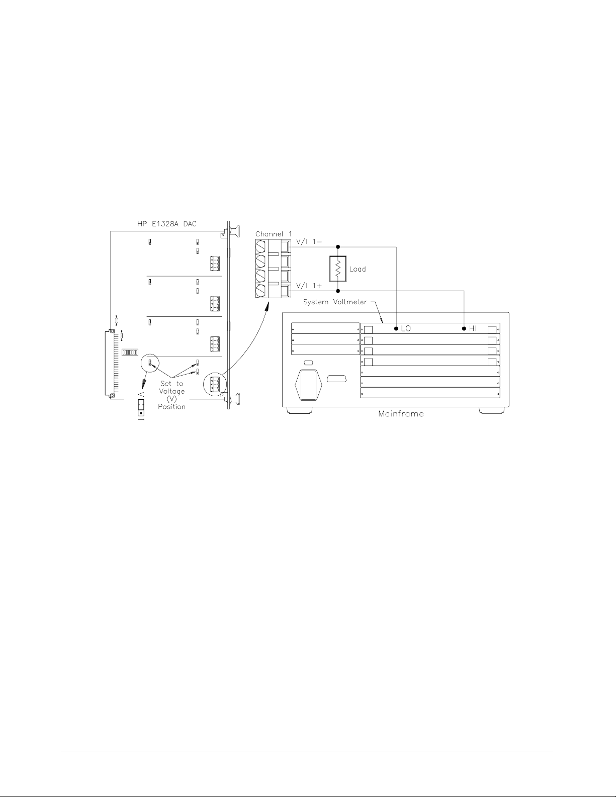
Figure 3-1 shows how to connect chann el 1 output terminals to the load and
system voltmeter (HP E1326B/E1411B). The D/A Converter must be
physically configured to provide voltage output on channel 1 (refer to page 17),
and then instructed to perform the adjustment. For the example, use:
– An HP-IB select code of 7, primary address of 09, and secondary
address of 09 for the D/A Converter.
– An HP-IB select code of 7, primary address of 09, and secondary
address of 03 for the syst em volt met er.
– An HP Series 200/30 0 Comput er with HP BAS IC.
Figure 3-1. Electronic Vo ltag e Adju stmen t
Execute:
10 REAL A,B,C
20 OUTPUT 70909;"*RST" !Reset the D/A Con ve rter to its
30 OUTPUT 70909;"CAL1:STAT OFF" !Configure c hannel 1 to the
40 OUTPUT 70909;"VOLT1 MIN" !Configure c hannel 1 to outpu t
50 OUTPUT 70909;"*OPC?" !Hold prog ram exe cution un til
60 ENTER 70909;D !Dummy variable hol ds
70 OUTPUT 70903;"MEAS:VOLT:DC?" !Configur e the sy stem voltm eter to
80 ENTER 70903;A !Store minimum voltage reading.
90 OUTPUT 70909;"VOLT1 DEF" !Configure c hannel 1 to outpu t
default state ; perform se lf -test .
non-calibrat ed mode .
the minimum voltage (-12 volt s).
the first output is complete . When
done, gene rate an operation
complete flag.
operatio n co mple t e flag .
make a DC voltage measurement.
the default voltage (0 volts).
Chapter 3 Using the HP E1328A 21
Page 22

100 OUTPUT 70903;"MEAS:VOLT:DC?" !Configure the system vo ltm eter to
make a DC voltage measurement.
110 ENTER 70903;B !Store default vol tage reading.
120 OUTPUT 70909;"VOLT1 MAX" !Configure c hannel 1 to outpu t
130 OUTPUT 70903;"MEAS:VOLT:DC?" !Configure the syste m v olt me ter
140 ENTER 70903;C !Store maximum voltage reading.
150 OUTPUT 70909;"CAL1:VOLT" ;A;B;C!Enter the me asure d minimu m,
the maximum volt age (+12 vol ts ).
for a DC voltage measurement.
default, and max imum value s.
New adjust ment constants a re
calcul ated and stored for
channel 1.
Comments • Test Hook-up. If possible, calibrate to the same load (and leads)
that the D/A Converter will be providing the voltage output to.
Connect the voltmeter leads as close as possible to the load.
• Voltmeter. Any 5
1
⁄2-di git voltmeter wit h accura cy o f at least
(0.015% of reading +1mV) can b e us ed when performing the
adjustment. HP recommends using the HP E1326B/E1411B
1
5
⁄2-Digit Multimeter for a system voltmeter, or the HP 3457 for an
external voltmeter (reco mmended for current).
• Electronic Current Adjustment. If a channel is only to be used for
voltage output, it is not necessary to p erform the current adjustment.
22 Using the HP E1328A Chapter 3
Page 23
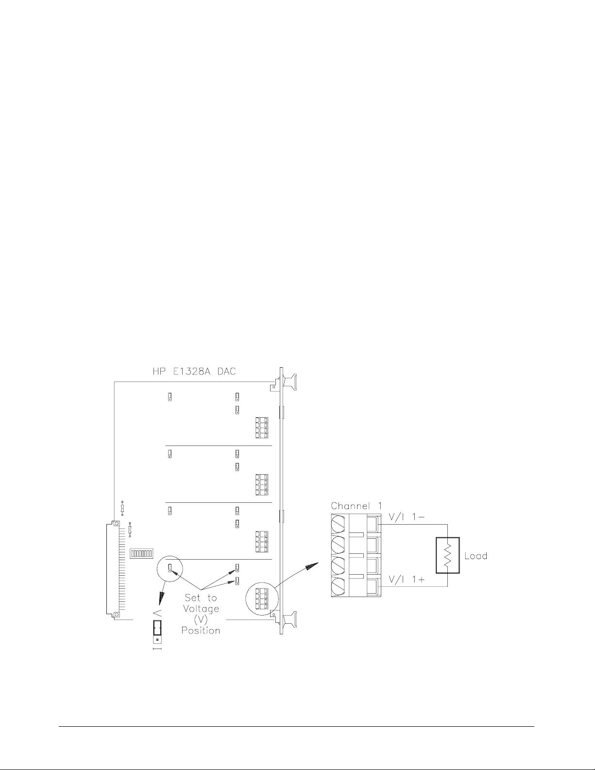
Outputting Voltage
– Will output voltag e on channels 1, 2, 3, and/or 4.
– Range is 10.922 Vdc in calibrat ed mode and 12 Vdc i n
non-calib rated mode per chan nel .
– Range can be increased to a maximum of 43.600 Vdc in calibrated
mode and 48 Vdc in non-calibrated mode by connecting all four
channels i n s eries.
– Remote sensing is available to ensure the selected voltage is
available at the load.
Example: Voltage
Output in Calibrated
Mode
Figure 3-2 shows how to connect chann el 1 output terminals to the load. The
D/A Converter must be physically configured to provide voltage output on
channel 1 (refer to page 17), and then instructed to output +10.00000 Vdc on
channel 1 in the calibrated mode.
Execute:
CAL1:STAT ON Sets channel 1 to calibrated mode.
VOLT1 10.00000 Configures ch anne l 1 for voltage
and sets output at termin als to
10.00000 Vd c .
Figure 3-2. One Channel Vo ltage O ut put
Chapter 3 Using the HP E1328A 23
Page 24
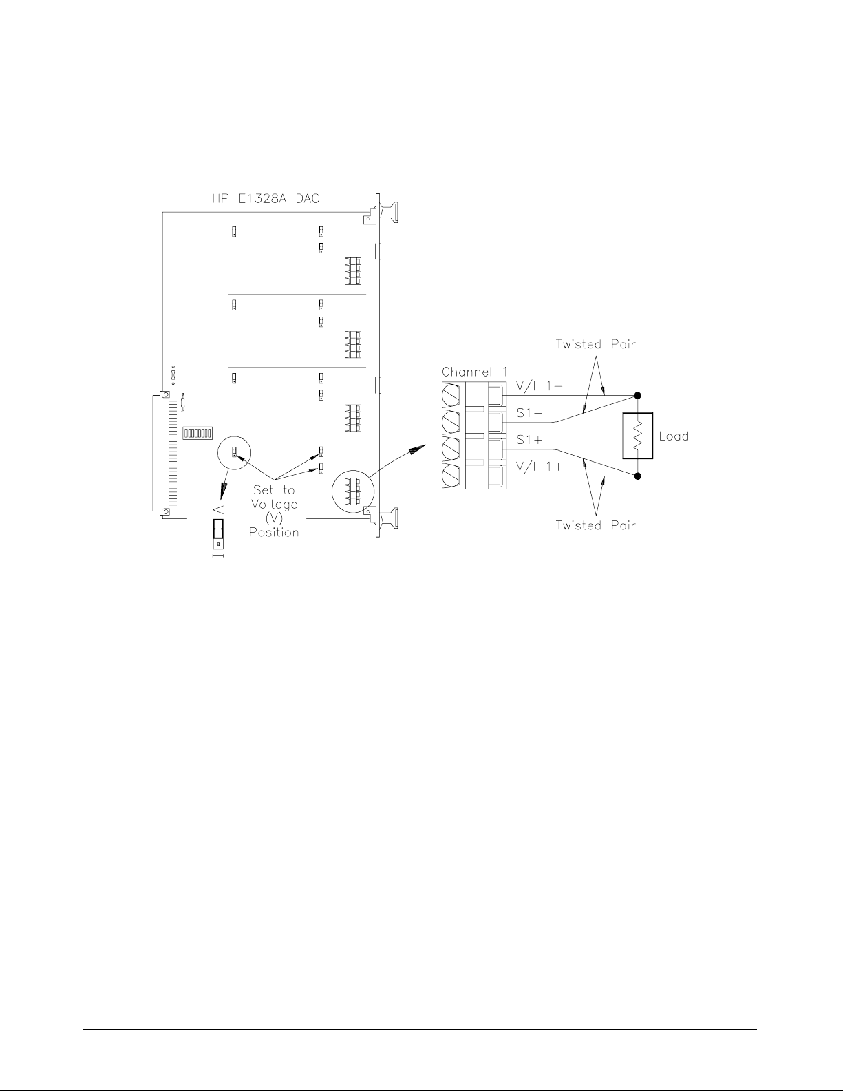
Example: Voltage
Output in Calibrated
Mode with Remote
Sensing
Figure 3-3 shows how to connect the sensing terminals to the load. The
D/A Converter physical configuration and instructions are identical to those
describ ed earlier.
Figure 3-3. One Chan nel Voltag e Ou tp ut with Remote Sen sin g
Example: Expanding
Voltage Output Range
in the Calibrated Mode
with Remote Sensing
Figure 3-4 shows how to configure channel 1 and 2 output terminals in
series to increase the range, connecting the sense terminals, and connecting
to the load. The D/A Converter must be physically configured to provide
voltage output on channels 1 and 2 (refer to page 17), and th en instructed to
output a specific voltage on channels 1 and 2 in order to obtain a total of
+20.00000 Vd c in the calib rated mode. For the examp le, use:
– an HP-IB select code of 7, primary address of 09, and secondary
address of 09 for the D/A Converter;
– an HP Series 200/300 comput er w ith HP BA S IC.
Execute:
10 OUTPUT 70909;"*RST" !Reset the D/A Con ve rter to its
default state.
20 OUTPUT 70909;"VOLT1 10.00000" !Configure channel 1 for voltage
and sets output at termin als to
+10.00000 V in the calib rate d
(defaul t) mode.
30 OUTPUT 70909;"VOLT2 10.00000" !Configure channel 2 for voltage
and sets output at termin als to
+10.00000 V in the calib rate d
(defaul t) mode.
24 Using the HP E1328A Chapter 3
Page 25
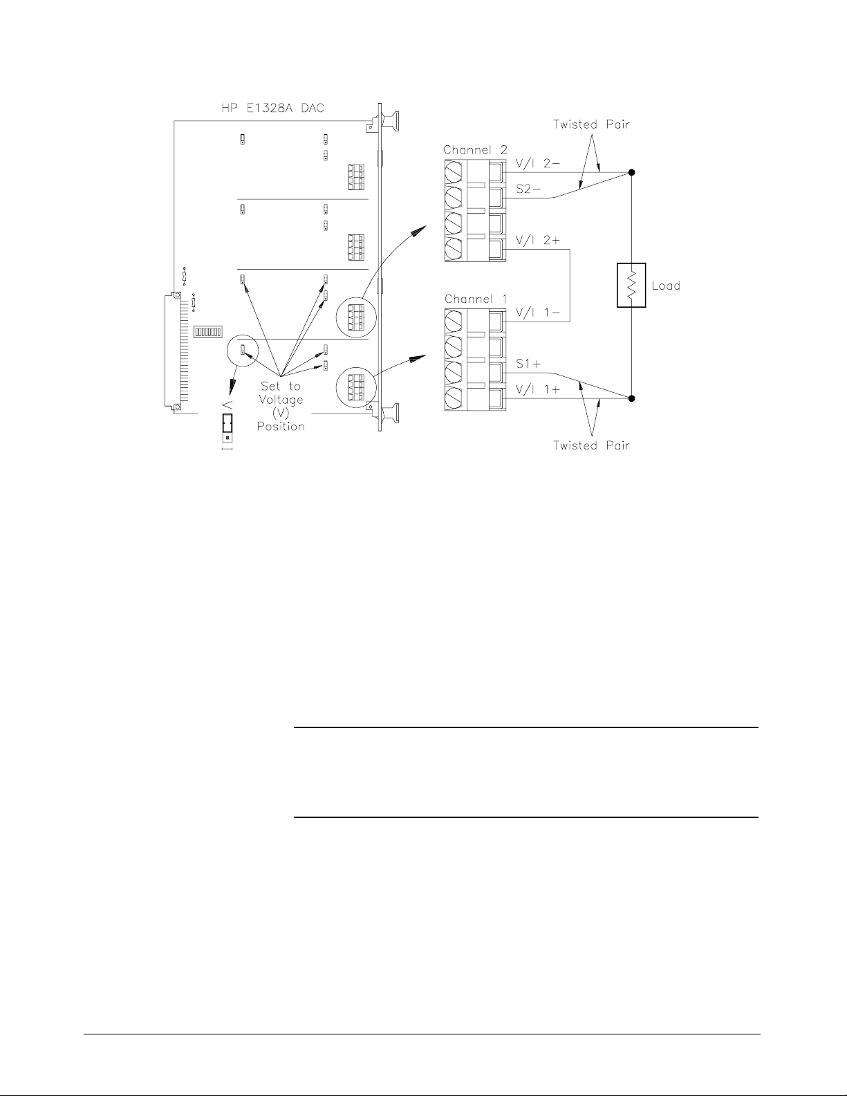
Figure 3-4. Extending Voltage Output Range
Comments • Sense Terminals. Use of remot e sensing is recommended to
compensate for voltage drops in t he test leads. This ensures an
accurate voltage is present at th e load. If not in use, do not make any
connection to the SENSE terminals.
• Compliance Current. The maximum current available when
outputting a volt age is 24 mAdc. This means, that at 12 V dc, the
load resistance should be at least 500Ω. See Chapter 4 for further
explanation on compliance current and load resistance.
• Isolation. Channel-to-channel or channel-to-chassis isolation is
rated at 250 Vrms (350 Vdc/ac p eak).
WARNING Do not exceed the rated isolation voltage. Damage may result if
channels of the same D/A Co nverter are connected to separate phases
of 3-phase power lines.
• Incorrect Jumper Setting. If a channel is configured for current
and instructed to output voltage, an error will be generat ed.
Chapter 3 Using the HP E1328A 25
Page 26

Electronic Current Adjustment
The electronic current adjus tment is used to update the stored current
constants f or each channel , an d should be perfo r m ed :
– on initial set-up;
– periodically (24 hours or 90 days) to maintain desired output
accuracy (see Appendix A);
– when a ±5°C change in temperature from last adjustment performed
has occurred;
– when the type of load is changed;
– or anytime accuracy is in doubt.
The adjustment procedure is performed for each channel as follows:
1. Configure the desired channel(s) for current output
(refer to page 17).
2. Connect the load to the desired D/A Converter channel.
Connect a multimeter to measure current at the load.
3. Set th e D/A Converter channel to the non-calibr a ted mode.
Note The electronic adjustment must be performed in the non-calibrated mode
(step 3), or errors in the adjustment constant will occur.
4. Set th e channel’s output to min imum (–24 mAdc). Measure and
1
record to 5
5. Set th e channel’s output to default (0 mAdc). Measure and record t o
1
⁄2-digits the actual output at the load.
5
6. Set the channel’s output to maximum (+24 mAdc). Measure and
record to 5
7. Record the minimum, default, and maximum values and send them as
parameters to the
will be calculated and stored from the entered values.
8. Repeat steps 2 through 7 for all desired channels.
⁄2-dig its th e actual out put at t he load.
1
⁄2-dig its th e actual out put at t he load.
CALibration command. N ew adjustment constants
26 Using the HP E1328A Chapter 3
Page 27

Example: One Channel
Electronic Current
Adjustment Using an
External Multimeter
Figure 3-5 shows how to connect channel 1 output terminals to the load and
external multimeter (HP 3457A). The D/A Con verter must be physi cally
configured to pro vide cur r ent outpu t on channel 1 (refer to pag e 17), and
then instructed to perform the adjustment. For the example, us e:
– An HP-IB select code of 7, primary address of 09, and secondary
address of 09 for the D/A Converter.
– An HP Series 200/300 computer with HP BASIC.
Execute:
10 REAL A,B,C, !Define variab le s use d to store
20 OUTPUT 70909;"*RST" !Reset the D/A Con ve rter to its
30 OUTPUT 70909;"CAL1:STAT OFF" !Configure c hannel 1 to the
40 OUTPUT 70909;"CURR1 MIN" !Configure channel 1 to output the
50 PRINT “RECORD AS MINIMUM” !Message on scree n instruc ts to
60 INPUT “ENTER RECORDED MIN: ”,A !Message on screen instruc t s to
70 OUTPUT 70909;"CURR1 DEF" !Configure c hannel 1 to outpu t
80 PRINT “RECORD AS DEFAULT” !M essa ge on screen instruc t s to
90 INPUT “ENTER RECORDED DEF: ”,B !Message on screen instructs to
100 OUTPUT 70909;"CURR1 MAX" !Configure channel 1 to output the
110 PRINT “RECORD AS MAXIMUM” !Message on scree n instruc ts to
120 INPUT “ENTER RECORDED MAX: ”,C!Message on screen instructs to
130 OUTPUT 70909; “CAL1:CURR ”;A;B;C,!Enter the measured minimum,
measured valu es.
default state and performs a
self-test.
non-calibrat ed mode .
minimum current (–24 mAdc).
record the measure me nt on the
multimeter as minimum.
enter the recorde d min imum
value. Enter and pre ss R ETUR N.
the default current (0 mAdc).
record the measure me nt on the
multimeter as default.
enter the rec orde d defa ult value .
Enter and press RE TURN .
maximum current (+24 mAdc).
record the measure me nt on the
multimeter as maximum.
enter the rec orde d maximu m
value. Enter and pre ss R ETUR N.
default, and max imum value s.
New adjust ment constants a re
then calcula te d and store d fo r
channel 1.
Chapter 3 Using the HP E1328A 27
Page 28
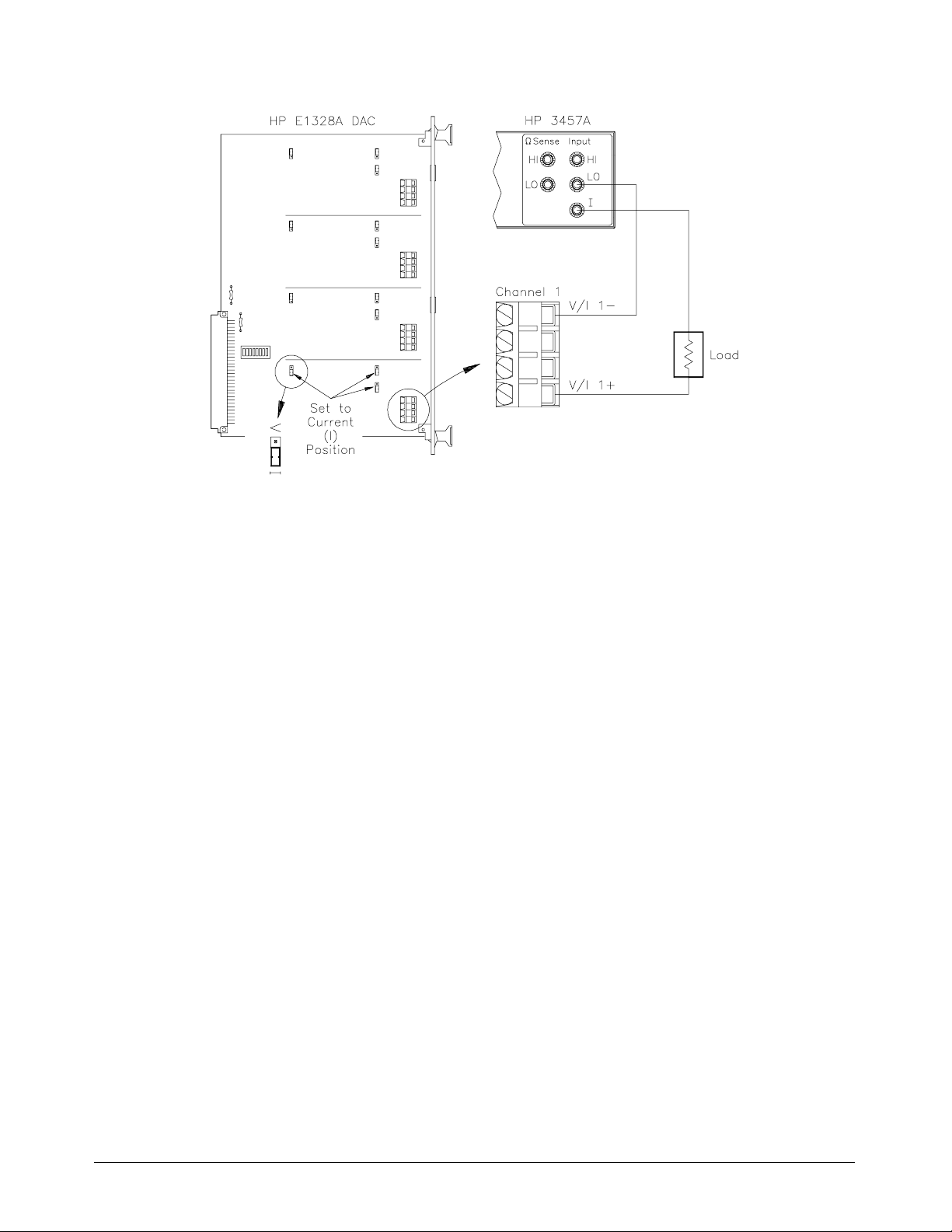
Figure 3-5. Electronic Current Adjustment
Comments • Test Hook-up. If possible, calibrate to the same load (and leads)
that the D/A Converter will be providing the current output to.
Connect the multimeter leads as close as possible to the load.
• Multimeter. Any 5
1
⁄2-digit (or greater) multimeter with DC current,
with an accuracy of at least (0.02% o f rea d ing +1A) ca n be used
when performing the adjustment. HP recommends using the
HP 3457 A.
• Electronic Voltage Adjustment. If a channel is only to be used for
current output, it is not necessary to perf orm t he volta ge ad justment.
28 Using the HP E1328A Chapter 3
Page 29
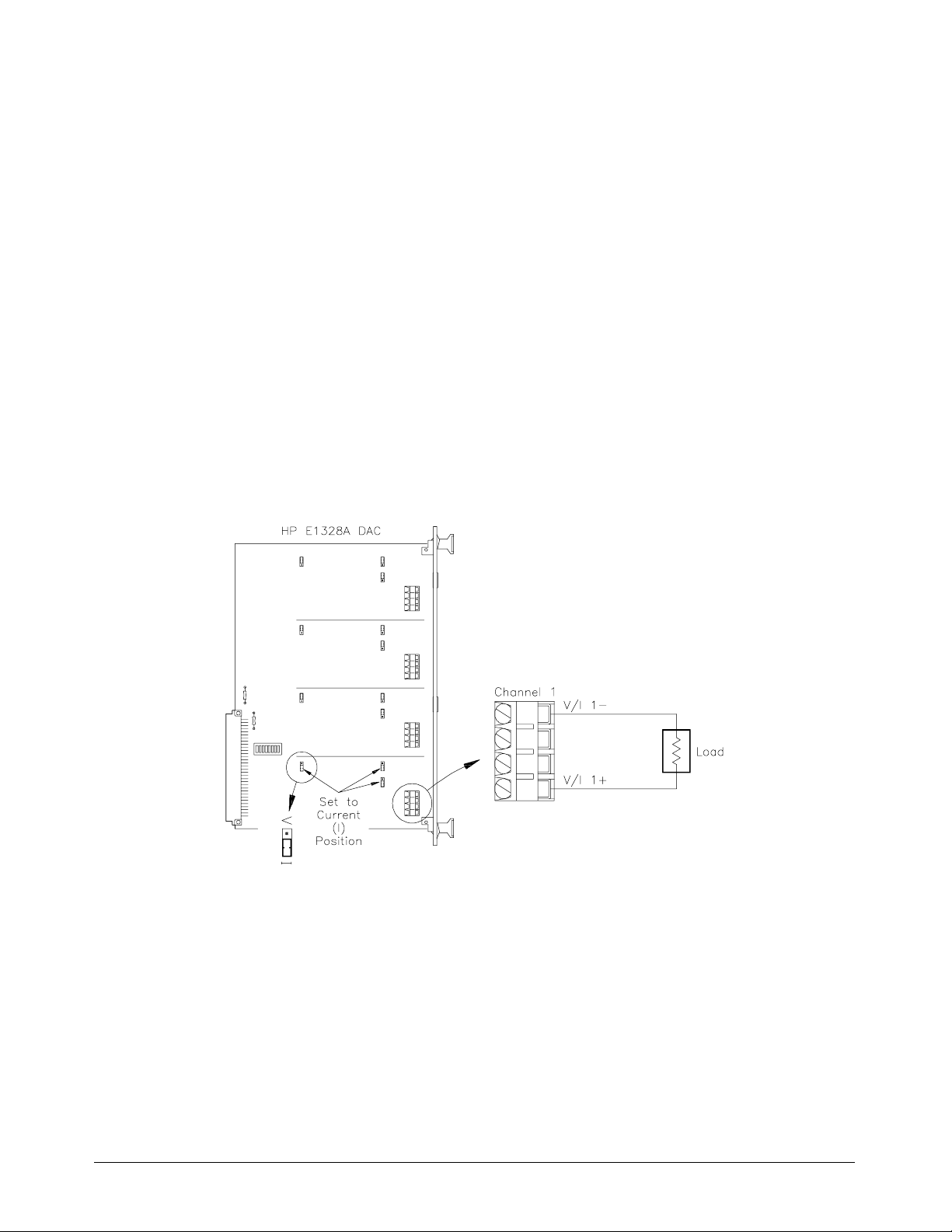
Outputting Current
– Will output current on channels 1, 2, 3, and/or 4.
– Range is 21.844 mAdc i n calibr ated mode and 24 mAdc in
non-calib rated mode per chan nel .
– Range can be increas ed to a maximum 87.376 m A dc i n calibr at ed
mode and 96 mAdc in non-calibrated mode by connecting all four
channels i n parallel.
Example: One Channel
Current Output in
Calibrated Mode
Figure 3-6 shows how to connect channel 1 output terminals to the load.
The D/A Converter must be physically configured to provide current output
on channel 1 (refer to page 17), and th en instructed to output +20.00 000
mAdc on channel 1 in the calibrated mode.
Execute:
CAL1:STAT ON Sets channel 1 to calibrated mode.
CURR1 0.020000 Configures channel 1 for current
and sets output at termin als to
20.000 mAdc.
Figure 3-6. One Channel Curren t Outpu t
Example: Expanding
Current Output Range
in the Non-Calibrated
Mode
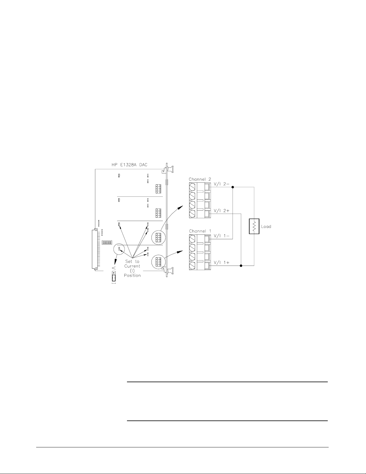
Figure 3-7 shows how to configure channel 1 and 2 output terminals in
parallel to increase the range, and how to connect to the load. The D/A
Converter must be phys ically configured t o pr ovide current output on
channels 1 and 2 (refer to page 17), and then instructed to output a specific
current on channels 1 and 2 in order to obtain a tota l of + 48.00000 mAdc in
the non-calibrated mode. For the example, use:
– An HP-IB select code of 7, primary address of 09, and secondary
address of 09 for the D/A Converter.
– An HP Series 200/300 comput er with HP BA SIC.
Chapter 3 Using the HP E1328A 29
Page 30
Execute:
10 OUTPUT 70909;"*RST" !Reset the D/A Con ve rter to its
default state.
20 OUTPUT 70909;"CAL1:STAT OFF" !Configure c hannel 1 to the
non-calibrat ed mode .
30 OUTPUT 70909;"CAL2:STAT OFF" !Configure c hannel 2 to the
non-calibrat ed mode .
40 OUTPUT 70909;"CURR1 MAX" !Configure channel 1 for current
and sets output at termin als to
maximum (+24 mAdc) in
non-calibrat ed mode .
50 OUTPUT 70909;"CURR2 MAX" !Configure channel 2 for current
and sets output at termin als to
maximum (+24 mAdc) in
non-calibrat ed mode .
Figure 3-7. Extending Current Output Ran ge
Comme nt s • Sense Terminals. Do not make any connection to the SENSE
terminals when outputting current.
• Compliance Voltage. The maximum voltage available when
outputting a current from one channel is 13 Vdc. This means that at
24 mAdc, the load resistance should not exceed 541. See Chapter 4
for further explanation on compliance voltage and load resistance.
• Isolation. Channel-to-channel or channel-to-chassis isolation is
250 Vrms (350 Vdc/a c peak).
WARNING Damage may result if channels of the same D/A Converter are
connected to separate phases of 3-phase power lines. Do not exceed the
rated isolation voltage.
30 Using the HP E1328A Chapter 3
Page 31
Understanding the HP E1328A
Using This Chapter
This chapter explains techniques to output voltage and current levels using
the 4-Channel D/A Converter. This chapter contains the following sections:
• Commands for D/A C onverter Op erat ion . . . . . . . . . . . . . . . Page 31
• Volta ge Outpu t. . . . . . . . . . . . . . . . . . . . . . . . . . . . . . . . . . . . Page 32
• Remote Sense. . . . . . . . . . . . . . . . . . . . . . . . . . . . . . . . . . . . . Page 33
• Curren t Out put. . . . . . . . . . . . . . . . . . . . . . . . . . . . . . . . . . . . Page 36
• Queryi ng t he D/A Converter . . . . . . . . . . . . . . . . . . . . . . . . . Page 37
Commands for D/A Converter Operation
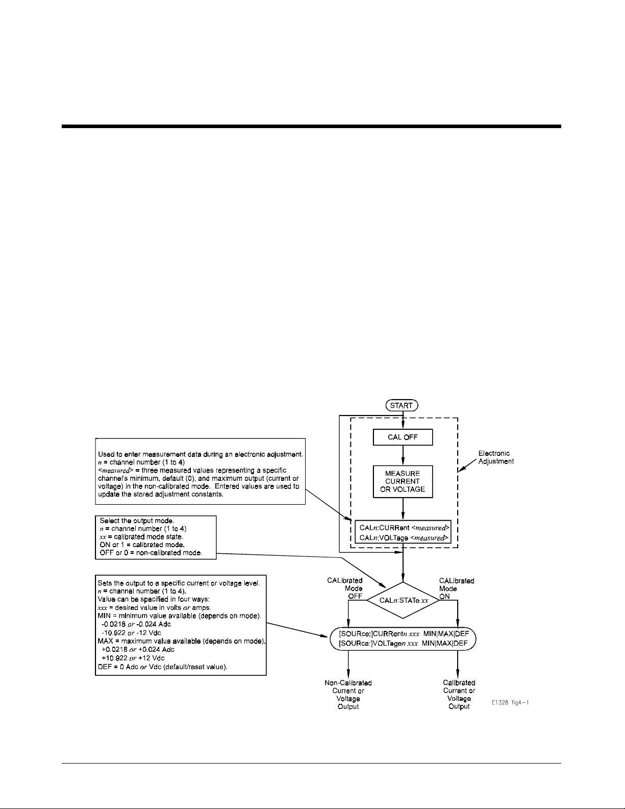
Outputting voltages and currents from the D/A Converter consists of
configuring the hardware for the type of output desired, then selecting the
output t y pe, level, and mode. When necessary, an electr onic adjustment is
performed to maintain calibrated mode output accuracy.
Chapter 4
Figure 4-1. D/A Converter Commands
Chapter 4 Understanding the HP E1328A 31
Page 32
Voltage Output
The proper seq uence of operation for out putting a volta ge from the D/A
Converter is provided below. Refer, as necessary, to Chap t ers 2 and 3 for
additional op era t ing information.
1. Det ermine t he number of voltage outputs required, and configure the
necessary channel jumpers for voltage (refer to page 17).
2. Connect the output leads t o th e correct channel V/I + and - terminals
(refer to pag e 18). If ext ending the output range, c onnect the
required number of channels in series to obtain the desired output
(refer to pages 24–25).
3. If remote s ensing will be used, con nect leads to the S + and terminals (ref er to pages 24 –25). If remote sensing will not be used,
leave the SENSE termi nals disco nnec t ed.
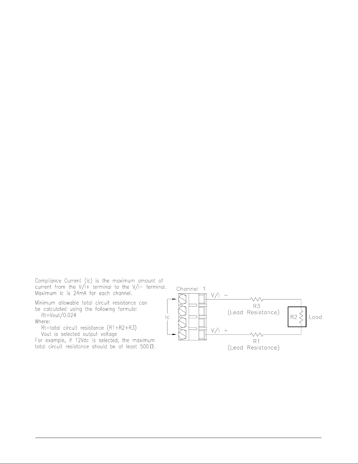
4. Verify t hat the compliance current will no t be exceeded by
calculating the total circuit resistance using Figure 4-2.
5. Install the D/A Converter in the mainframe and connect the output
leads to the load (refer to Chapter 3).
6. Determine if an electr oni c vo ltage a djust ment is n ecessa ry ( r ef er to
page 20).
7. Enter and execute the proper instructions to output the desired
voltage(s), and t he des ired mode (refer to pages 23– 25).
Figure 4-2. Output Voltag e Comp lian ce Curren t
32 Understanding the HP E1328A Chapter 4
Page 33
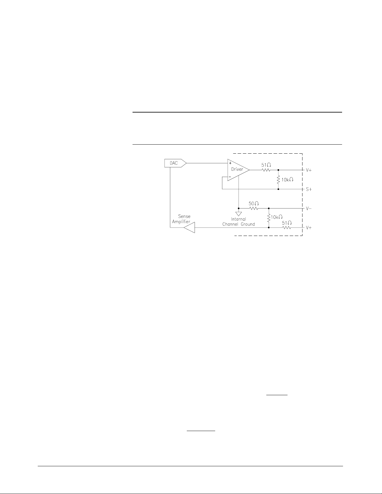
Remote Sense
Note Remot e sense operation is availa ble for volta ge output only. During current
In remote sens e mode, the D/A Convert er measures the actual voltage
delivered at the load, then compensates for any difference between the
measured value and the selected value. The equivalent output circuit for the
D/A Convert er using re mot e sense is shown in Figur e 4-3.
output, the SENSE termina ls must remain disconnected.
Maximum Lead
Resistance
Figure 4-3. Remote Sense Operati on
When using the D/A Converter to output voltage using remote sensing
(refer to pag es 24–25), the maximum allowab le lea d resistance is calculated
using the following procedure (refer to Figure 4-3):
1. The driver amplifier’s max imum output voltage is less than 19 V
(17 V typical) w he n the load resista n ce is infinite.
2. The maximum output current available is 24 mA.
3. The maximum load voltage (V
) is normally 10.92 V, and never
L(max)
exceeds approximately 12 V. The maximum load voltage is calculated
as follows:
V
L(max)
≤ (24mA)(R
load
)
4. The maximum voltage drop allowed across the resistance of the leads
(V
drop (max)
5. Therefore the maximum allowable lead resistance (R
) is calculated as follows:
≤
= 17 − V
V
drop(max)
V
L(max)
V
drop(max)
R
lead
L(max)
R
load
− (101Ω)
V
L(max)
R
load
) is:
lead
Chapter 4 Understanding the HP E1328A 33
Page 34
Oper ation with
Fixed Voltage
Sources in Series
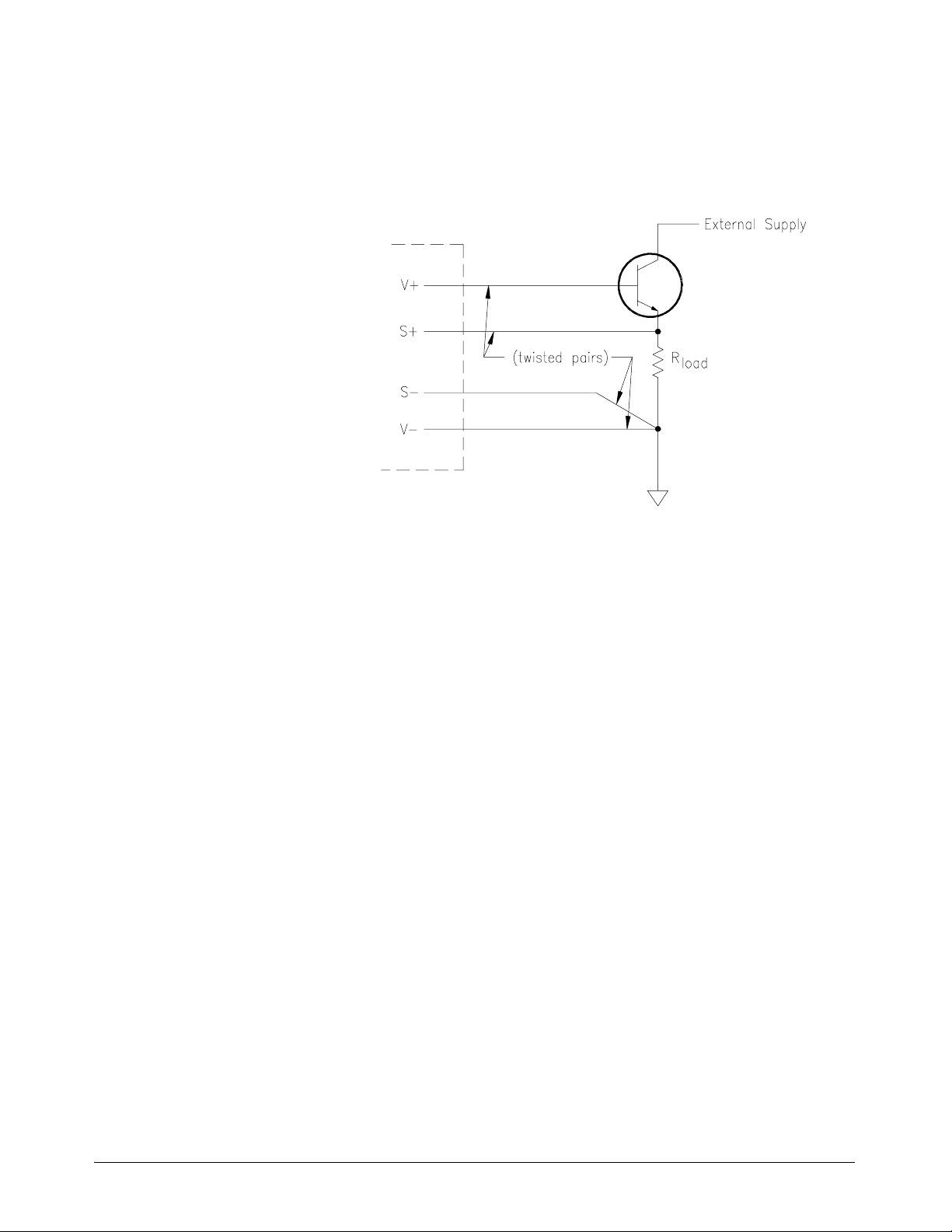
If a fixed volta ge must be placed in series with the load, connect the voltage
sourc e t o the V + lead for the most accurate output. A n example of this type
of application is shown in Figure 4-4. The emitter follower configuration
increases the total available output current.
Figure 4-4. Emitter Follo wer Co nfig uratio n
If the fixed voltage source is placed in the V- lead, a small error will occur
in the output voltage. An output error of approximately 0.05% of the
voltage between V- a n d S- occurs d u e to the 51Ω protection resistor in
series with the S- terminal. This error does not occur if the voltage between
V- and S- is due solely to lead resistance, provided that an el ectron ic
adjustment has been performed with the same load and lead configuration as
under actu al oper atin g cond itions.
Adjustment Under
Actual Le ad a n d
Load Conditions
Whenever possible, perform electronic adjustments with the D/A Converter
connected to th e leads and load to b e used in operation. An electr o nic
adjust ment perf ormed u n der actual op erat ing c on diti ons prov ides the b est
output ac curacy.
If an electronic adjustment is performed with a different V- lead resistance than
that encountered under actual operating conditions, small errors will occur in
the output voltage due to the effect of the 51Ω protection resistor mentioned in
the preceding section, “Operation with Fixed Voltage Sources in Series”.
34 Understanding the HP E1328A Chapter 4
Page 35
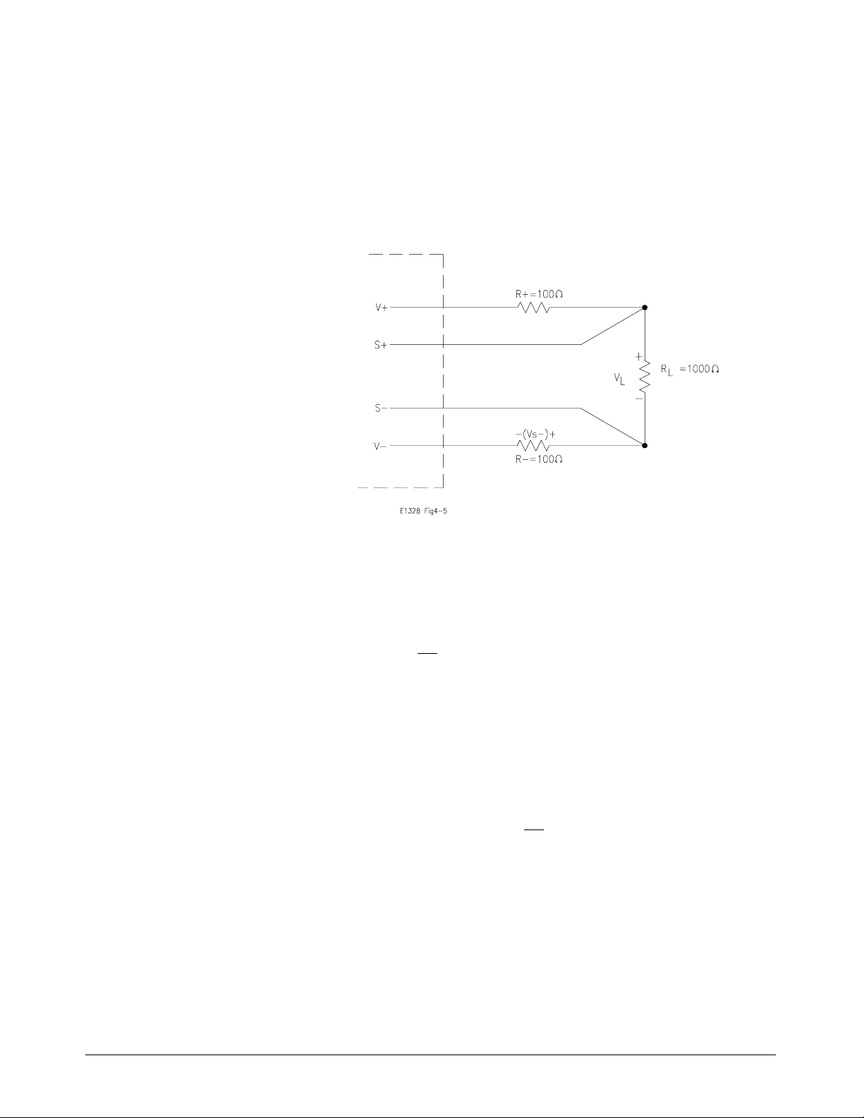
As an example, suppose there was a difference of 100Ω between the lead
resistances used for the electronic adjustment and those encountered under
actual op erati ng conditions. This would cau se the voltage between V- and
S- during electronic adjustment to be different than the voltage between Vand S- under actual operating c onditions. The output error pr oduced can be
understood by referring to the example sho wn in Figure 4-5 and the
following explanation.
Figure 4-5. Lead Resistance and Electron ic Adjustmen t
R- is the change in lea d r es istance. The differenc e in voltage drop acr oss Rbetween the electronic adjustment and actual operating conditions is as
follows:
−
V
S
− = V
R
L
R
L
This difference in voltage drop across R- is also the chang e in voltage
between V- and S- for electronic adjustment versus actual op erat ing
conditions. As discussed in the preceding section, this change in the voltage
between V- and S- produces an output error of approx ima t ely 0.0 5% of the
voltage between V- an d S-. In this case:
Output Error =
= (0.0005) V
(0.0005)(V
)
S−
R−
L
R
L
For th e circu it shown in Figure 4-5, the additional output error (caused by
the change in lead resistance after electronic adjustment) is 0.005% of t he
load voltage.
Chapter 4 Understanding the HP E1328A 35
Page 36
Current Output
The proper seq uence of operation for out putting a current fr om the D/A
Converter is provided below. Refer, as necessary, to Chap t ers 2 and 3 for
additional op era t ing information.
1. Det er mine t he number of current outputs requ ired, and conf igure the
necessary channel jumpers for current (refer to page 17).
2. Connect the output leads to the correct channel V/I + and - terminals
(refer to page 18). Do not connect anything to the S + and - terminals.
If extending the output range, connect the required number of channels
in parallel to obtain the desired output (refer to page 29).
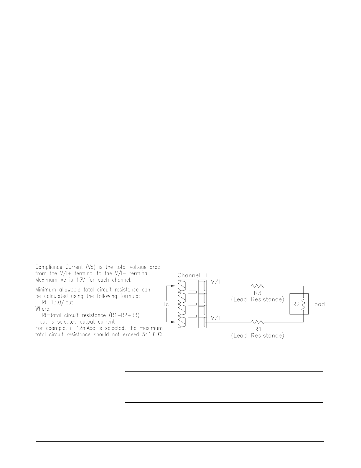
3. Verify that the co mpliance voltage will not be exceeded b y
calculating the total circuit resistance using Figure 4-6.
4. Install the D/A Converter in the Mainframe and connec t the output
leads to the load (refer to Chapter 3).
5. Determine if an electr oni c current ad just ment is n ecessa ry ( refer to
page 26).
6. Enter and execute the proper instructions to output the desired
current(s), and t he desired mode (refer to pages 29–30).
Figure 4-6. Output Current Co mpl ian ce Vo ltag e
Note The compliance current is 24 mA. The maximum short circuit current
(e.g. R2 = 0 in Figure 4-6) is limited to ≤30 mA by the HP E1328A.
36 Understanding the HP E1328A Chapter 4
Page 37

Querying the D/A Converter
This section summarizes the query commands you can use to determine the
configurati on or stat e of the D/A Converter. All commands end with the
"?" which puts the data int o the output buff er where you can retrieve it.
Calibration mode state: CALibraten:STATe?
Current output leve l: SOURce:CURRentn?
Display channel selected: DISPlay:MONitor:CHANnel?
Display present output setting: DISPlay:MONitor:STRing?
System error: SYSTem:ERRor?
V/I jumper position: SOURce:FUNCn?
Voltage out put le vel: SOURce:VOLTn?
(n = channel number)
(n = channel numb er)
(n = channel number)
(n = channel number)
Chapter 4 Understanding the HP E1328A 37
Page 38

Notes
38 Understanding the HP E1328A Chapter 4
Page 39

HP E1328A Command Reference
Using This Chapter
This chapter describes Standard Commands for Programmable Instruments (SCPI)
commands and summariz es IEEE 488.2 Co mmon (*) Commands applica ble to the
4-Channel D/A Converter.
• Command Types . . . . . . . . . . . . . . . . . . . . . . . . . Page 39
• SCPI Command Reference . . . . . . . . . . . . . . . . . . . . Page 41
• CALibration Subsystem . . . . . . . . . . . . . . . . . . . . . . Page 42
• DISPlay Subsystem . . . . . . . . . . . . . . . . . . . . . . . . Page 45
• [SOURce:] Subsystem . . . . . . . . . . . . . . . . . . . . . . Page 47
• SYSTem Subsystem . . . . . . . . . . . . . . . . . . . . . . . Page 49
• IEEE 488.2 Common Command Quick Referenc e . . . . . . . . Page 50
• HP E1328A Command Quick Reference . . . . . . . . . . . . . Page 51
Command Types
Chapter 5
Common
Command
Format
SCPI
Command
Format
This manual c overs two types of commands: IEEE 488.2 Common and SCPI
Commands.
The IEEE 488.2 standard defines the c ommon c ommands that perform functions
like reset, self- test , and so o n. Common comma nds are four `or five charact ers in
length, always begin with the asterisk character (*), and may inc lude one or more
parameters. The command keyword is separat ed from the first param et er b y a space
character. Two common commands are:
*RST and *TST?
SCPI comm a nds perform functions like selectin g output le vel, selecting output
mode, and qu erying data. A subs ystem command structure is a hierarchical
structure that us ually consists o f a t op leve l (or root) command, one or more lower
level sub commands, and their parameters. The following example shows an
excerpt from a typical subsystem:
[SOURce:]
VOLTage
[SOURce:]
is replaced by the channel number in the range of 1 to 4), and
is the root command, VOLTagen is the second-level sub command (where n
n <level>
<level> is a pa rameter.
Chapter 5 HP E1328A Command Reference 39
Page 40

Command
Separator
A colon (:) always separat es one command from the next lower-level command as
shown below:
DISPlay:MONitor[:STATe] <mode>
Abbreviated and
Short Commands
Implied
Commands
The comman d syntax shows most commands as a mix of upper and lower case
letters. The upper case letters indicate the abbreviated spelling for the command.
For shorter program lines, send only the abbrev iated form. For better program
readability, you may s end the entire command. The instrument accepts either the
abbreviated form or the entire command.
For example, if the c ommand ref eren ce syntax s hows the command
SOUR and SOURce are both acceptable forms. Other forms of SOURce, such as
SOURC, will generate an error. You may us e upp er cas e and lower case letters;
SOURCE, source, and SoUrCe are acceptable.
SOURce, then
Implied commands are those which appear in square brackets ([ ]) in the command
syntax. (Note that the brackets are not part of the command and are not sent to
the instrument). Suppose you send a second-level command but do not send the
preceding implied command. In this ca se, the instrument assumes you intend to use
the implied command and it responds as if you had sent it. Examine an excerpt
from the
[SOURce:] subsystem shown below:
[SOURce:]
VOLTage
n?
The root command [SOURce:] is an implied co mman d. To query t he instrument
about a voltage l ev el set on channel 1, send either of the following commands:
Parameters
SOUR:VOLT1? or VOLT1?
Parameters are enclosed in greater than/less than symbols (< >) in the command
syntax. When more than one parameter is allowed, the parameters are separated by
a vertical line ( | ).
Parameter Types. The following table contains explanations and examples of
parameter types you might see later in this chapter. Parameters must always be
separated from the keywords by a space.
Parameter Type Explanations and Examples
Numeric Accepts all commonly used decimal representations of numbers
includi n g optional signs, decimal points, an d scient i fic notation.
123 or 123E2; -123 or -1.23E2; .123, 1.23E-2, or 1.23000E-01.
Special cases include MINimum, MAXimum, and DEFault.
Boolean Represents a single binary condition that is eith er true or false.
1 or ON; 0 or OFF.
40 HP E1328A Command Reference Chapter 5
Page 41

Linking
Commands
Linking IEEE 488.2 Common Commands with SCPI Commands . Use a
semicolon (;) between the commands. For example:
*RST;VOLT1?
Linking M ultiple SCPI Co mma nds . U se both a semico lon (;) a n d a
colon (:) between the commands. For example:
VOLT1?;:CURR2?
SCPI Command Reference
The following sections describe the Standard Commands for Programmable
Instruments (SCPI) commands for the HP E1328A 4-Channel D/A Convert er
Module. Commands are listed alphabetically by subsystem and within each
subsystem. A command guide is printed in the top margin of each page. The guide
indicates the curre nt subs yst em on that page.
Chapter 5 HP E1328A Command Reference 41
Page 42

The CALibration subsystem selects the mode of operation (calibrated or
non-calibrated) under which a specific channel will operate, and is also used to enter
updated adjustment constants during electronic adjustment procedures.
Subsystem Syntax CALibrationn
:CURRent <measured | MIN | MAX | DEF>
:STATe <
:STATe?
:VOLTage <
CALibrationn:CURRent
CALibrationn:CURRent <measured | MIN | MAX | DEF> is used to enter a
channel’s mea sur e me nt data obtained dur ing an electroni c cur r ent a djustment.
These values are used to updat e the stored adjustment constants. The three
measured values are
MINimum (-24mA), DEFault (0mA), and MAXimum (+24mA).
CALibration
mode>
measured | MIN | MAX | DEF>
Note During an ele ctronic adjustment, the output cur r e nt must be measure d with the
channel configured in the non-calibrated mode (
output cur r ent is measured in the calibrated mode (
these measured values are entered using the
output current error s will result wh en t he channel is used in the calibrated mode.
CALibrationn:STATe OFF). If the
CALibratio n n:STATe ON), a n d
CALibrationn:CURRent command,
Parameters
Parameter Name Param eter Type Range of Values Default Values
CALibration
<
measured>
n
keyword 1, 2, 3, or 4 1
numeric -0.030 to -0.01 5
-0.005 t o +0. 005
+0.015 to +0. 03 0
Comme nt s • Channel Number: Select only one channel at a time.
• Related Commands: [SOURce:]CURRent n, CALibrationn:STATe
•
Measured Values: Three values (MIN | DEF | MAX) are measured in the
1
non-calibrated mode, then ent ered to 5
calculates and stores new adjustment constants. These stored constants are used
to maintain t he channel’s accuracy in the output curr e nt calibrated mode.
⁄2-digits. Once entered, the D/A Converter
Amps
42 HP E1328A Command Reference Chapter 5
Page 43
Example Entering Channel 4 Measurement Data.
This command enters the minimum, default, and maximum measured values
channel 4 out put during an electronic adjustment procedure.
CALibrationn:STATe
CALibrationn:STATe <mode> enables or disables the calibrated mode for a
specific channel.
Parameters
Comme nt s • Channel Number: Select only one channel at a time.
• Related Commands: CALibrationn:CURRent, CALibrationn:VOLTage,
[SOURce:]VOLTagen, [SOURce:]CURRentn
CAL4:CURR -0.02359, 0.00012, +0.02405
Parameter Name Param eter Type Range of Values Default Values
CALibration
<
mode>
n keyword 1, 2, 3, or 4 1
boolean 0 | 1 | ON | OFF 1 | ON
• *RST Condition: CALibration:STATe 1
Example Setting Channel 3 to Non-Calibrated Mode.
CAL3:STAT OFF Set channel 3 mode to non-cal ib rate d ou tpu t.
CALibrationn:STATe?
CALibrationn:STATe? qu eries a specific channel about the currently selected
mode of operation.
indicates o perating under non-ca librated mode.
1 (one) indicates operating under calibrated mode, and 0 (zero)
Chapter 5 HP E1328A Command Reference 43
Page 44

CALibrationn:VOLTage
CALibrationn:VOLTage <measured | MIN | MAX | DEF> is used to enter a
channel’s mea sur e me nt data obtained dur ing an electroni c voltage adjustment.
These values are used to updat e the stored adjustment constants. The three
measured values are
Note During an electronic a djustment, the output voltage must be measure d w it h t he
channel configured in the non-calibrated mode (
output voltage is measured in the calibrated mode (
these measured values are entered using the
output vo ltage error s will result whe n t he channel is used in the calibrated mode.
Parameters
Parameter Name Param eter Type Range of Values Default Values
CALibration
<
measured>
MINimum (-12V), DEFaul t (0V), and MAXimum (+12V).
CALibrationn:STATe OFF). If the
CALibratio n n:STATe ON), a n d
CALibrationn:VOLTage command,
n
keyword 1, 2, 3, or 4 1
nume r ic -15. 0 t o -8. 0
-1.0 to +1.0
+8.0 to +15.0
Volts
Comments • Channel Number: Select only one channel at a time.
• Related Commands: CALibrationn:STATe, [SOURce:]VOLTagen
• Measured Values: Three values (MIN | DEF | MAX) are measured in the
1
non-calibrated mode, then ent ered to 5
⁄2-digits. Once entered, the D/A Converter
calculates and stores new adjustment constants. These stored constants are used
to maintain t he channel’s accuracy in the output v oltage calibrated mode.
Example Entering Channel 2 Measurement Data.
This command enters the minimum, default, and maximum measured values
channel 2 out put during an electronic adjustment procedure.
CAL2:VOLT -12.00346, 0.00352, +11.98342
44 HP E1328A Command Reference Chapter 5
Page 45

The DISPlay subsystem monit ors t he channel state of a selec ted module in a
mainframe. This command operates with mainframes that have a display, such as
the HP E1301A Mainframe.
Subsystem Syntax DISPlay
:MONitor
DISPlay:MONitor:CHANnel
DISPlay:MONitor:CHANnel <channel | MIN | MAX | DEF | AUTO> selects the
channel to be monitored when the monitor mode is enabled.
Parameters
:CHANnel <
:CHANnel? <
[:STATe] <
:STRing?
mode>
DISPlay
channel | MIN | MAX | DEF | AUTO>
channel>
Parameter Name Parameter T ype Range of Valu es Default Values
channel>
<
numeric 1 to 4 | DEF | MIN | MAX | AUTO 1
Comme nt s • Selecting Monitor Channel Values: When using the DISPlay:MONitor:CHANnel
command, numbers 1 to 4 select a specific channel to be monit or ed. In addition
to selecting a specific channel, four other values can be entered.
MINimum selects channel 1, MAXimum selects channel 4, and AUTO activa tes the
DEFault and
automatic mode where the last channel changed is displayed.
• Monitor Mode on an HP 1301A Mainframe Display: Selecting the channel
causes the inf ormation to be displayed on t he mainframe’s front panel. The
DISPlay:MO Ni tor:STRing? command must be used to display the information on
the computer. The following shows the monitor mode display string on the
display of an HP E1301 A Ma infr ame:
CHAN1 10.00000E01 VOLT, CAL 1
The example above shows channel 1, 10 Vdc, in the calibrated mode.
• Related Commands: DISPlay:MONitor[:STATe]
Example Selecting Channel 1 for Monitoring.
DISP:MON:CHAN 1
Chapter 5 HP E1328A Command Reference 45
Page 46
DISPlay:MONitor:CHANnel?
DISPlay:MONitor:CHANnel? <channel> performs two different functions
dependent o n if the parame ter (
If <channel> is no t used (bl ank): queries which channel will be displayed when the
monitor mode is enabled.
chan nel chan g ed).
<channel>) is used.
-1 indicates operating in automatic mode ( displays the last
1 through 4 indicates which specific channel will be displayed.
If <channel> is used (
DEFault and MINimum always returns 1, and MAXimum always returns 4.
DISPlay:MONitor[:STATe]
DISPlay:MONitor[:STATe] <mode> turns t he monitor mode on or off.
Parameters
Parameter Name Param eter Type Range of Values Default Values
<
Comme nt s • The [:STATe] parameter is optional. Ther ef ore, either of the following command
statements is valid:
DISP:MON:STAT ON or DISP:MON ON
• Monitoring Module Channels: DISPlay:MONitor:STATe ON or
DISPlay:MONitor:STATe 1 turns the monitor mode on to show the selected
channel stat e.
the monitor m ode of f.
• Selecting the Channel to be Monitored: Use the DISPlay:MONitor:CHANnel
command t o s elect t he channel.
DEF | MIN | MAX): queries available channel information.
mode> boolean 0 | 1 | ON | OFF 0 | OFF
DISPlay:MONitor:STATe OFF or DISPlay:MONitor:STATe 0 turns
• *RST Condition: DISPlay:MONitor[:STATe] OFF
Example Enabling the Monitor Mode.
This command selects monitor mode to on.
DISP:MON:STAT 1
DISPlay:MONitor:STRing?
DISPlay:MONitor:STRing? queries the channel for output inf ormation. Channel is
selected by the
DISPlay:MO Ni tor[:STATe] command. Display string is two 25-character fields
separated by a comma.
46 HP E1328A Command Reference Chapter 5
DISPlay:MONitor:CHANnel command, and enabled b y the
Page 47
The [SOURce:] subsystem selects a channels output type (voltage or current), and level.
Subsystem Syntax [SOURce:]
CURRent
CURRent
FUNCtion
VOLTage
VOLTage
[SOURce:]CURRentn
[SOURce:]CURRentn <level | MIN | MAX | DEF> configures th e D/A Convert er to
output current on a sp ecifi ed channel (n) at a spec ifie d le v el.
Parameters
Parameter Name Parameter Type Range of Values Default Values
n
<
level>
[SOURce:]
n <level>
n?
n?
n <level>
n?
numeric 1 , 2 , 3, or 4 1
numeric -0.024 to +0.0 24 | MIN |
MAX | DEF
0
Comments • Channel Number: Select only one channel at a time.
• If a “Settings Conflict” Error Occurs: See “Selecting Voltage or Current Output”
on page 17.
• Related Commands: CALibrationn:STATe
*RST Condition: [SOURce:]CURRent 0
•
Example Setting Channel 2 to Current Output at +20 mAdc.
[SOURce:]CURRentn?
[SOURce:]CURRentn? queries a specific channel about the currently selected
current level on the channel specified by n. If the specified channel is configured
for voltage, an error wi ll b e generated. Output format is as fo llows:
SOUR:CURR2 .020
SDDDDDDDESDDD
Where: S = + or -
D = 0 to 9 with floating decimal point
E = base 100 expo nent de limiter
Chapter 5 HP E1328A Command Reference 47
Page 48
[SOURce:]FU NCtionn?
[SOURce:]FUNCtionn? queries a specific channel about the configuration of the
specified V/I jumper in the channel’s digital section. Does not indicate V/I jumper
position of the two jumpers in the analog section. Returns
the "I" position or
Parameters
Parameter Name Parameter Type Range of Values Default Values
Comments • Channel Number: Select only one channel at a time.
[SOURce:]VOL T ag en
[SOURce:]VOLTagen <level | MIN | MAX | DE F > configures the D/A Conv erter to
output voltage on a specified chann el at a sp ec if ied le ve l.
Parameters
Parameter Nam e Parameter Type Range of Values Default Values
<
level>
CURR if the jumper is in
VOLT if the jumper is in the "V" position.
n
n
numeric 1 , 2 , 3, or 4 1
num eric 1, 2, 3, or 4 1
numeric -12 to +12 | MIN | MAX | DEF 0
Comments • Channel Number: Select only one channel at a time.
• If a “Settings Conflict” Error Occurs: See “Selecting Voltage or Current Output”
on page 17.
• Related Commands: CALibrationn:STATe, CALibrationn:VOLTage
*RST Condition: [SOURce:]VOLTage 0
•
Example Setting Channel 1 to Voltage Output at +10.000000 Volts.
[SOURce:]VOLTagen?
[SOURce:]VOLTagen? queri e s a s pecific cha n n e l a bout the current ly s e lec t ed
voltage lev el on the channel specified by n. If the specified channel is configured
for current, a n error wi ll b e generated. Output format is as fo llows:
VOLT1 10.000000
SDDDDDDDESDDD
Where: S = + or -
D = 0 to 9 with floating decimal point
E = base 100 expo nent de limiter
48 HP E1328A Command Reference Chapter 5
Page 49

The SYSTem subsystem returns the error numbers and error me ssages in the err or
queue, an d returns t he types of mo dules (car ds ).
Subsystem Syntax SYSTem
:ERRor?
SYSTem:ERRor?
SYSTem:ERRor? returns the error numbers and error messages in the error queue.
See App endix C for a listing of the error numbers a nd me ssages.
Comme nts • Error Numbers/Messages in the Error Queue: Each error generated by the
D/A Converter stores an error number and corresponding error message in the
error queue. Each error message can be up to 255 characters long.
• Clearing the Error Queue: An error numb er/ message is removed from the
queue each time the
first-in, first-out. When the queue is empty, each
returns "0, N o error". To clear all error numbers/message s in th e queue, execute
*CLS command (see the mainframe opera t ing manual).
the
SYSTem
SYSTem:ERRor? command is sent. The errors are c lear ed
SYSTem:ERRor? command
• Maximum Error Numbers/Messages in the Error Queue: The queue holds a
maximum of 30 error numbers/messages for the D/A Converter. If the queue
overflows, the last e rror number/ message in the queue is replaced by "-350, Too
man y errors". T h e leas t recent e r ror n umbers/mes sa ges re m a i n in the q ueu e and
the most recent are discarded.
Example Reading the Error Queue.
This command qu eri es the error qu eue, reads an d prints the nu mbers/messa ge.
SYST:ERR?
Chapter 5 HP E1328A Command Reference 49
Page 50

IEEE-488.2 Common Command Quick Reference
The following table lists the IEEE 488.2 C ommon (*) Commands that can be
executed b y the D/ A Co nverter Module. For more inf ormat ion on C ommon
Commands, refer to the HP E1300A/E1301A User’s Manual, the HP E1406A
Command Module User’s Manual , or the ANSI/IEEE Standard 488.2-1987.
Command Title Description
*IDN?
*RST
*TST?
*OPC
*OPC?
*WAI
*CLS
*ESE
*ESE?
*ESR?
*SRE
*SRE?
Identification Query
Reset
Self-Test Query
Operation Compl et e
Operation Complet e Query
Wait to Compl ete
Clear Statu s Register
Event Status Enable
Event Status Enable Query
Event Status Register Query
Service Request Enable
Service Request Enabl e
Query
Returns Identificat i on String of the D/A Converter.
Performs a 5-second self-test, places 0Vdc/0mAdc on all channels,
and then sets the mode of all channels calibrated (ON).
Returns 0 unless self-test fails.
(See note below).
Returns a 1 if previous operation is complete.
(See note below).
Clears all Status Register (see SYSTem:ERRor?).
(See note below).
(See note below).
(See note below).
(See note below).
(See note below).
*STB?
*RCL <n>
*SAV <n>
Read Status Byte Q uery
Recall Saved Stat e
Sav e S tate
(See note below).
Recalls previousl y stored D/A Conv er ter Modul e configuration.
n> indicate s locatio n in mem or y from 0 to 9.
<
Stores the current D/A Conv ert er Modul e conf i gurat ion in memory.
n> indicate s locatio n in mem or y from 0 to 9.
<
Note These co mman ds have little or no effect on D/A Converter operation. R efer to the
HP E1300A/E1301A Mainf rame User’s Manua l, the H P E1406A Command Mod ule
User’s Manual, or the ANSI/IEEE Stan dard 488. 2-198 7 for more information.
50 HP E1328A Command Reference Chapter 5
Page 51

HP E1328A Command Quick Reference
The following table summarizes SCPI Commands for the HP E1328A.
SCPI Commands Quick Reference
Command
Subsystem Command/Parameter Description
CALibration
DISPlay
[SOURce:] :CURRent
n :CURRent <measured>
:STATe <
:STATe?
:VOLTage <
:MONitor:CHANnel <
:MONitor:CHANnel? <
:MONitor[:STATe] <
:MONitor:STRing?
mode>
measured>
n <level>
channel>
channel>
mode>
Enters three measured values to update the
channel’s stored current adj ustment constant.
Selects mode to calibrated (1) or non-calibrat ed (0).
Returns mode channel is currently operati ng under.
Enters three measured values to update the
channel’s stored voltage adj ustment constant.
Enters the desired c hannel number to be viewed
when in monitor mode (1 to 4 or auto).
Returns the presently selected channel number to be
viewed when in monitor mode (1 to 4 or auto); or the
DEFault, MINimum, or MAXimum available channel
number.
Selects monitor mode to on (1) or off (0).
Returns the selected channel number (1 to 4),
output configurati on (voltage or current ), output
level, and mode (calibrat ed or non-calibr ated).
Sets the specified channel (
current level.
n) to output the specific
:CURRent
:FUNCtion
:VOLTage
:VOLTage
SYSTem :ERRor? Returns t he e rror num b e r/m essag e in the error queue.
n?
n?
n <level>
n?
Returns the current level the specified channel (
is currently set to output.
Returns the present position of the V/I jumper in
the specified channel’s (
Sets the specified channel (
voltage level.
Returns the voltage level the specified channel (
is currently set to output.
n) digital section.
n) to output the specific
n)
n)
Chapter 5 HP E1328A Command Reference 51
Page 52

Notes
52 HP E1328A Command Reference Chapter 5
Page 53

Appendix A
HP E1328A Specifications
DC Voltage
Range: ± 10.92 V (cal on)
± 12 V (cal off)
Resolution:
333 µV programming i nterval (cal on)
16-bit resolution (cal off)
Monoto nic t o 2 mV at 25°C
Accuracy: ±± (% of output + v olts)
Conditions: cal on, within ± 5°C o f
cal temperature and same load as at calibration.
24-hour: ±± (0.05% of output + 3.3 mV)*
90-day: ± (0.15% of output + 29 mV )
1 year: ± (0.30% of output + 110 mV)
Temperature Coefficient: ± (.01% + 0.667 mV)/°C
*(For loads ≥ 500 Ω, the maxi mum additio nal
error due to using a load different than that
used for calibration is ± 0. 02% of output.)
Output Current:
Compliance current: 24 mA
Short circuit current: ≤ 30mA
Differential Ripple and Noise:
< 2 mV
(20 Hz – 250 kHz, 1 kΩ load)
in HP 75000 mainfr ame
rms
DC Current
Range: ± 21.8 mA (cal on)
± 24.0 mA (cal off)
Resolution:
667 nA programming interval (cal on)
16-bit resolution (cal off)
Monotonic to 4 µA at 25°C
Accuracy: ±± (% of output + amps)
Conditions: Ca l on, within ± 5°C of cal temperature
and same load as at calibration.
24-hour: ± (0. 05% of output + 7 µA)
90-day: ± (0.15% of output + 59 µA
1 year: ± (0.3% of output + 220 µA)
Temperature Coefficient: ± (0.01% + 1.33 µA)/°C
Output Voltage:
Compliance voltage: 13 V
Max open circuit voltage: ≤ 19V
Typical output impedance: > 25 MΩ
Differential Ripple and Noise:
< 4 µA
(20 Hz – 250 kHz, into 100 Ω)
in HP 75000 ma inframe
rms
Common Mode Noise
(V/I to chassis, 1 kΩ):
<30 mV i n HP 75000 Main frame
Appendix A HP E1328A Specifications 53
Page 54

General
Settling Time:
Conditions: single channel, to rated accuracy
µs (cal on), 500 µs (cal off)
750
Isolatio n:
250 V
(channel-to-channel or chassis)
15 Vdc/ac, peak (c hannel- to-s ense)
Max wire size: 16AWG
Module Size/Device Type: B, register-based
Connectors Use d: P1
No. Slots: 1
VXIbus Interface Capability: Slave, A16, D16
, 350 Vdc/ac p eak
rms
Power Requirements:
Voltage:
+ 5 + 12
Peak module
current, IPM (A): 0.40 0.50
Dynamic module
current, IDM (A) : 0.02 0.01
Watts/Slot: 6.5
Coo ling/Slot:
0.11 mm H
O @ 0.52 liter/sec.
2
Humidity: 65%, 0 to 40°C
Operating Temperature: 0 to 55 °C
Storage Temperature: -40 to 75°C
EMC, RFI, Safet y:
meets FTZ 1046/1984 , CSA 556B,
IEC 348, UL 12 44
Interrupt Level: None
Net Weight (kg ): 0.7
54 HP E1328A Specifications Appendi x A
Page 55

HP E1328A Register-Based Programming
Using This Appendix
The contents of this appendix are:
• Addressing the Registers . . . . . . . . . . . . . . . . . . . . . . . . . . . . Page 55
• Register Definitions . . . . . . . . . . . . . . . . . . . . . . . . . . . . . . . . Page 59
• Register Descriptions. . . . . . . . . . . . . . . . . . . . . . . . . . . . . . . Page 60
• A Register-Based Algorithm . . . . . . . . . . . . . . . . . . . . . . . . . Page 71
• Progra mming E xam ples. . . . . . . . . . . . . . . . . . . . . . . . . . . . . Page 72
Addressing the Registers
To access a specific register for either read or write operations, the address of
the register must be used. Register addresses for the plug-in modules are found
in an address space known as VXI A16. The exact location of A16 within a
VXIbus master’s memory map depends on the design of the VX Ibus master
you are using; for the HP E1300/1301 Mainfr ame and HP E1405/E1406
Command Module, the A16 space location starts at 1F0000
Appendix B
1
.
16
The A16 space is further divided so that the modules are addressed only at
locations above 1FC000
register addresses (40
address (set by the address switch on the module) times 64 (40
of the D/A Converter module, the factory default address setting is 72 or 48
Register addresses for register-based devices are located in the upper 25%
of VXI A16 address space. Ev ery VXI device (up to 256) is allocated a
64-byte block of addresses.
Figure B-1 shows the register address loca tion within A16. Figure B-2 shows
the location of A16 address space in the HP E1405/E1406 Command Module.
1 The "16" at the end of the address indicates a hexadecim a l base number .
within A16. Further, every module is allocated 64
16
). The address of a module is determined by its logical
16
). In the case
16
16
.
Appendix B HP E1328A Register-Based Programming 55
Page 56
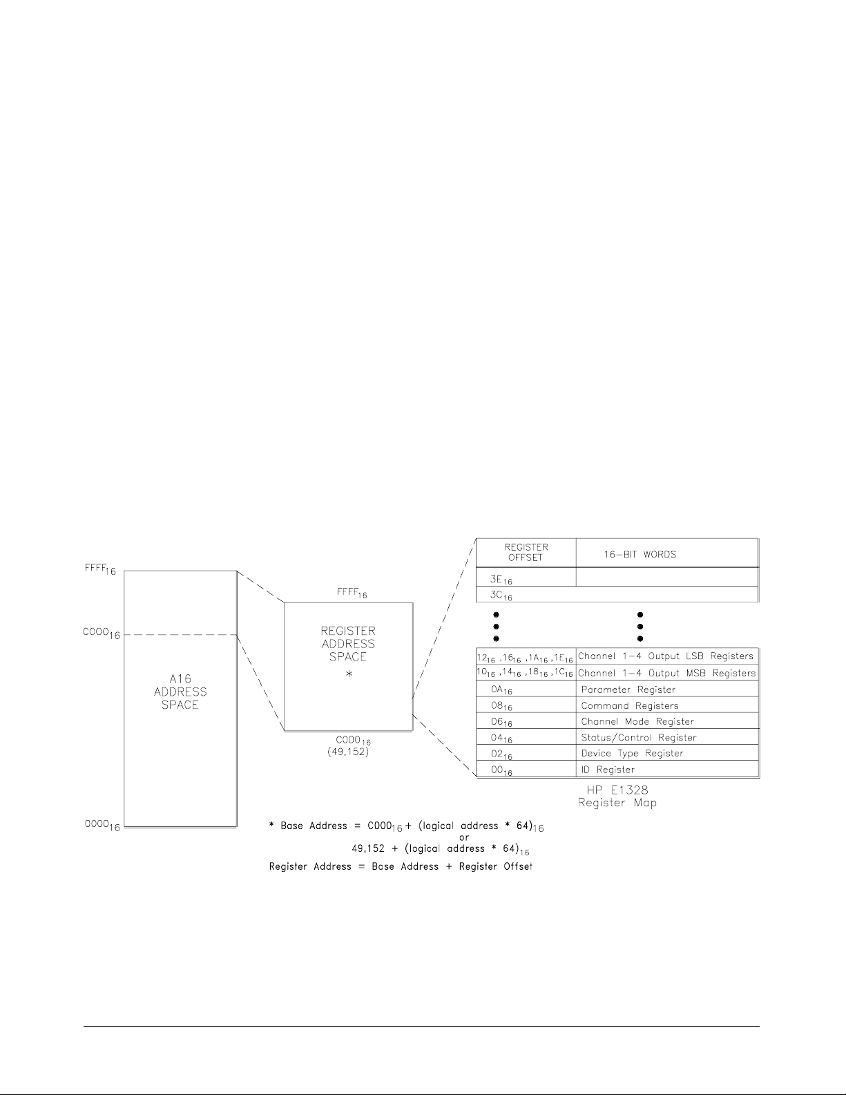
The Base Address When you are reading or writing to a module register, a hexadecimal or
decimal re gister address is specified. T his address consists of a base
address plus a register offset. The base address used in register-based
programming depends on whether the A16 addre ss space is outside or ins ide
the HP E1405/06 Command Module.
A16 Address Spac e
Outside the Command
Module (on the VXIbus)
When the HP E1405/06 Command Module is not part of your VXIbus
system (Figure B-1), t he HP E13 28’s ba se address is compu t ed as :
C00016 + (LADDR * 64)
16
or (decimal)
49,152 + (LADDR * 64)
where C00016 (49,152) is t he starting locatio n of the regis ter addresses,
LADDR is the module’s logical address, a nd 64 is the number of address
bytes per VXI devic e. For examp le, the HP E1328’s factory set logical
address is 72 (48
C00016 + (72 * 64)16 = C00016 + 120016 = D200
), theref ore it will ha ve a b as e addr e ss of:
16
16
or (decimal)
49,152 + (72 * 64) = 49,152 + 4,608 = 53,760
Figure B-1. Register Address Location within A16 Address Space
56 HP E1328A Register- Based Pr ogr amming Appendix B
Page 57
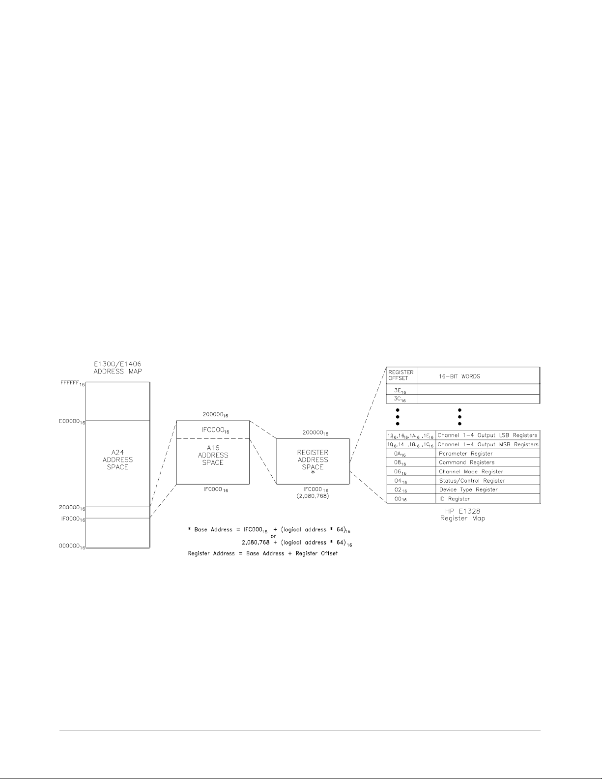
A16 Address Spac e
Inside the HP E1405/06
Command Module or
HP E1300/01 Mainframe
When the A16 addr e ss space is inside t he HP E1405/E1406 C ommand
Module (Figure B-2, the module’s base address is computed as:
1FC00016 + (LADDR * 64)
16
or
2,080,768 + (LADDR * 64)
where 1FC00016 (2,080,768) is the starting location of the VXI A16
address es, LADDR is the module’s logical ad dress, and 64 is the nu mber of
address bytes per reg ist er-based device. Again, the HP E1328’s factory set
logical address is 72. If this address is not changed, the module will have a
base address of:
1FC00016 + (72 * 64)16 = 1FC00016 + 120016 = 1FD200
or
2,080,768 + (72 * 64) = 2,080,768 + 4608 = 2,085,376
16
Figure B-2. Address Space in the HP Mainframe and Command Module
Appendix B HP E1328A Register-Based Programming 57
Page 58

Register Offset The register offset is the register’s location in th e bl ock of 64 address bytes
that belong to the module. For exampl e, the module’s Status/C ontrol
Register has an offset of 04
the offset is added to the base address to form the register address:
. When you write a command to this register,
16
D20016 + 0416 = D204161FD20016 + 0416 = 1FD204
or
53,760 + 4 = 53,764 2,085,376 + 4 = 2,085,380
Table B-1 shows the general programmin g method for accessing the
HP E1328A registers using different computers.
Table B-1. Accessing the HP E1328A Registers
Computer Progr am ming Method Base Address
HP E1300/01 IBASIC
(Absolute Addressing)
(select cod e 8)
External Computer
(over HP-IB to
HP E1300/E1301
Mainframe or
HP E1405/E1406
Comm and Modul e)
READIO (-9826, Base_addr + offset)
WRITEIO -9826, Base_addr + offset ; data
(positive select code = byte read or write
negative select code = word read or write)
READIO (8, Base_addr + reg number)
WRITEIO 8, Base_addr + reg number; data
VXI:READ? logical_address, offs et
VXI:WRITE logical_address, offset, data
DIAG:PEEK? Base_addr + offset, width
DIAG:POKE Base_addr + offset, width, dat a
Base_addr = 1FC000
or
= 2,080,768 + (LADDR * 64)
offset = register offset (Fi gur e B-2)
Base_addr = LADDR * 256
reg number = register offset (Fi gur e B-2)/ 2
Module logical addr ess setting (LADDR)
offset = register offset (Fi gur e B-2)
Base_addr = 1FC000
or
= 2,080,768 + (LADDR * 64)
offset = register offset (Fi gur e B-2)
16
+ (LADDR * 64)
16
+ (LADDR * 64)
16
16
16
V/382 Embedded
Computer
(C-Size s ystem)
HP RADI-EPC7
Embedded Computer
with SICL
LADDR: HP E1328A logical addr ess = 72
(LADDR * 64)
When using DIAG :PEEK? and DI AG :PO KE, t h e width (num b er of bits) is either 8 or 16.
: Multiply quant ity t hen convert to a hexadeci m al num ber (e.g. (72 * 64)16 = 120016)
16
READIO (-16, Base_addr + offset)
WRITEIO -16, Base_addr + offset; data
(positive select code = byte read or write
negative select code = word read or write)
iwpeek((unsigned short *)
(base_addr + offset))
iwpok e((un sig n ed shor t *)
(base_addr + offset),dat a)
Base_addr = C000
or
= 49,152 + (LADDR * 64)
offset = register offset (Fi gur e B-1)
INST device_name;
device_name = iopen
(“vxi, logical address”);
base_addr = imap
(device_name, I_MAP_VXIDEV, 0,1,NULL) ;
+ (LADDR * 64)
16
16
58 HP E1328A Register- Based Pr ogr amming Appendix B
Page 59
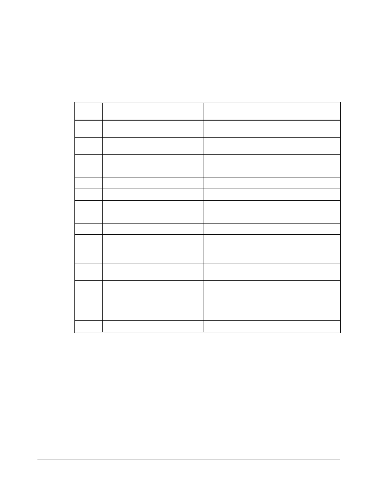
Register Definitions
Table B-2 lists the registers on the HP E1328A 4-Channel D/A Converter
Module and whether you can read or write to the registers.
Register
Offset Definition High Byte Low Byte
Table B-2. Register Map
1E
1C
1A
18
16
14
12
10
0E
0C
0A
08
06
04
Channel 4 LSB Output (write only) ignored Channel 4 Least
16
Significant Byte (LSB)
Channel 4 MSB Output (write only) ignored Ch annel 4 Most
16
Significant Byte (MSB)
Channel 3 LSB Output (write only) ignored Channel 3 LSB
16
Channel 3 MSB Output (write only) ignored Ch annel 3 MSB
16
Channel 2 LSB Output (write only) ignored Channel 2 LSB
16
Channel 2 MSB Output (write only) ignored Ch annel 2 MSB
16
Channel 1 LSB Output (write only) ignored Channel 1 LSB
16
Channel 1 MSB Output (write only) ignored Ch annel 1 MSB
16
16
16
Parameter Register
16
reserved reserved
reserved reserved
ignored Pa ramet er Register
(read or write to lower byte)
Command R egi st e r
16
ignor e d C ommand Regi st e r
(read or write to lower byte)
Channel Mode Register (read only) FF
16
Status/Contro l Register
16
Status/Cont rol Register Status/Control Register
16
Channel Mode Register
(read or write to lower byte)
02
00
Device Type Register (read only) Device Type R egister Device Type Register
16
Manufacture ID Register (read only) ID Register ID Register
16
Appendix B HP E1328A Register-Based Programming 59
Page 60
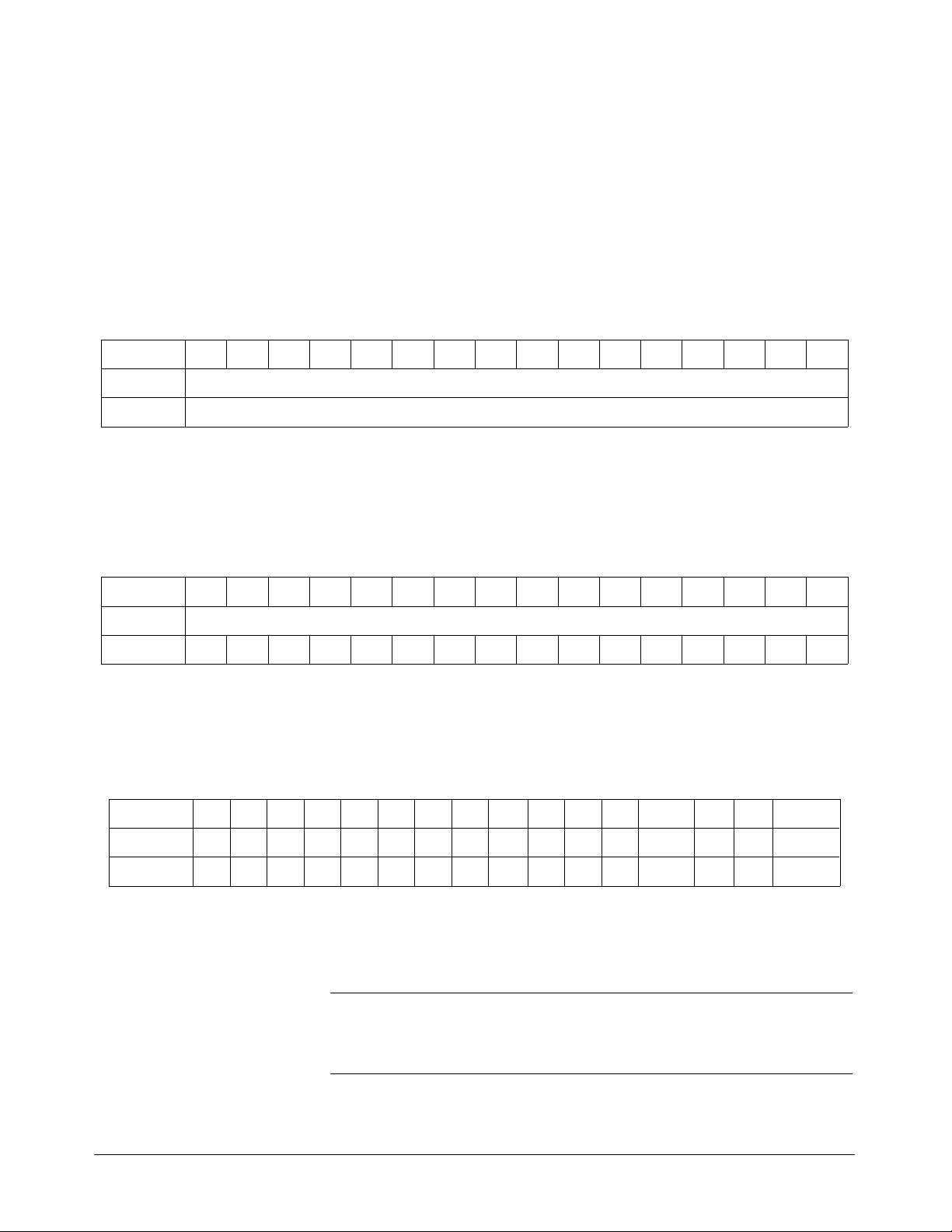
Register Descriptions
The following pages detail register descriptions for the HP E1328A
4-Channel D/A Converter Module.
Manufacturer ID
Register
Base + 00161514131211109876543210
Write Undefined
Read* Manufacturer ID
*Returns FFFF
= Hewlett-Pa ckar d A16 on ly regist er-b a sed.
16
Device Type
Register
Base + 02161514131211109876543210
Write Undefined
Read 1111111101111111
Reading this register returns FFFF16. This shows Hewlett-Packard as t he
manufactur e r and that the module is an A16 register based device.
Manufacturer ID Register (Read Only)
Reading this regist er retur ns FF7F16. This shows that the device is an
HP E1328A 4-Channel D/A Converter Module.
Device Type Register (Read Only)
Status/Control
Register
Eleven 1-bit fields provide information on equipment and operational status.
Refer to the register definitions and the following explanation for
Status/Cont rol Register info rmation.
Status/Control Register (Read/Write)
Base + 041615 14 13 12 11 10 9 8 7 6 5 4 3 2 1 0
Write ------------ - -SFISR
Read 1111S4S3S2S1DONER*IE*CF*READY PAS 1 C/P RDY
C/P RDY: (Ready - b it 0). A one (1) in this field indicates that the D/ A
Conver ter’s data buffer is empty and that data may be written to registers
through 1E16. Note: This bit was formerly called RDY.
08
16
Note This bit must be checked bef ore writing to registers 08
through 1E
16
16
(except the RESTART command).
60 HP E1328A Register- Based Pr ogr amming Appendix B
Page 61

Status Bit Precedence In addition to bit 0 indicati ng the D AC rea d y co ndition, bit 0 also
determines the validity of bits 6 - 11. When bit 0 is cleared (0), bits 6 - 11
may be invalid. Therefore, when monitoring bits 6 - 11, that bit AND bit 0
must both be true.
PAS: (Passed - bit 2). A z ero (0) in this field indicates that the D/A
Converter is either executing, or has failed a self test. A one (1) indicates
that the self test has successfully completed.
READY: (Ready - bit 3). A zero (0) in this field in combination with a one
(1) in the PAS field indicates that the D/A Converter is executing an
extended s elf t est. Note: This bit was for mer l y called EX* (Extended (n ot)).
CF*: (Checksum-failure (not) - bit 4). A zero (0) in this field indicates that
the D/ A C onvert er’s stored adjustment constants did n ot have the correc t
checksum, and may be incorrect.
Note If CF* is asserted, it is reco mmended that each channel be calibrated in both
voltage and current modes before using the D/A Converter in the calibrated
mode.
IE*: (I nt ernal-exception (not) - bit 5). A z ero (0) in this field indicates that
the D/A Converter has encountered an error in executing its program. To
clear the error, perform the steps below.
1. Write correct CAL-ON/CAL-OFF commands to each channel.
2. Write correct output data to each channel (ignore the state of the
settle bits).
3. Issue a RESTART command.
4. When IE * is one (1), repeat steps 1 and 2.
5. I f t his pr o ced ure fails, p er for m a s o f t res et .
Note Performing a soft reset (SR) will zero all outputs, cause the D/A Converter to
execute a self-test, and assert the SYSFAIL line. Therefore, it is recommended
that the SFI bit be set before performing a soft reset to avoid halting mainframe
operations.
Appendix B HP E1328A Register-Based Programming 61
Page 62

ER*: (Error (not) - bit 6). A zero (0) in this field indicates that an error ha s
occurred in executing a command. The error condition is cleared on receipt
of another command. The recommended way of clearing the error
condition is by sending the NULL command. Channel output operat ions
have no effect on this b it.
DON: (Done - bit 7). A one (1) this field indicates that the previ ous
command has been completed. Writing to the Command Regist er (08
16
)
when this bit is zero (0) may abort the command i n progress. Channe l
output operat io ns have no effect on this bit.
S1 through S4: (Settle Flags - bits 8 t o 11). A o ne (1) in one of these
fields indicates that the correspondi ng c hannel out put is stab le. A zero (0)
indicates that the channel output is or will be changing. Writing to a
channel when its settle flag is low (0) could corrupt the output data.
SR: (Soft Reset - bit 0). Writing a o ne (1 ) c auses the D/A C onver ter to
enter a reset state. Channel output data will be lost and all pending
commands wil l be terminat ed. Registers 08
through 1E16 cannot be
16
accessed whe n S o ft Reset is set. The D/A Converter will b e held in the
reset condition until a zero (0) is written to the SR bit, at which time the
power-on s elf test and start-up sequence will b e executed. It is
recommended that the SR bit remain high for >200 msec.
CAUTION Only perform a soft reset if the "RESTART" co mmand fails (see “Command
and Parameter Registers” later in this appendix). This is because when the
D/A Converter is soft reset, power is removed from the output channels, and
the output state during power-down is indeterminate.
SFI: (SysFail I nhibit - bit 1). Writing a one (1 ) inhibits the assertion o f t he
SYSFAIL line on the backplane.
62 HP E1328A Register- Based Pr ogr amming Appendix B
Page 63
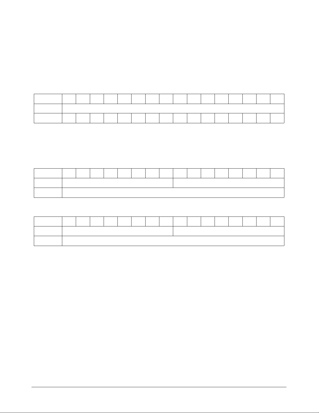
Channel Mode
Registers
V1 through V4 ( b its 0 to 3). A one (1 ) in an y o f t hese bits indicates that t he
corresponding channels digital s ect ion V/I jumper is configured to operate
in voltage output mode. A zero (0) indicates current output mode.
Configuration of the channel’s two analog section V/I jumpers are not
indicated; theref ore, it is essential that all three V/I ju mpers mat ch for eac h
channel.
Channel Mode Register (Read O nly)
Base + 06161514131211109876543210
Write Undefined
Read 111111111111V4V3V2V1
Chann el Outp u t
Register s
Eight registers (two per channel) allow output value to be set. Two writes
are required to set each channel. Refer to the register definitions and the
following explanat ion for Channel Output Re gist er information.
Channel Output MSB Registers (Write Only)
Base + *1514131211109876543210
Write Ignored MSB value
Read Undefined
*base + 10
Base + *1514131211109876543210
Read Undefined
*base + 12
for channel 1, base + 1416 for channel 2, base + 1816 for channel 3, or base + 1C16 for cha nnel 4.
16
Channel Outpu t LSB Regist ers (Write Only)
Write Ignored LSB value
for channel 1, base + 1616 for channel 2, base + 1A16 for channel 3, or base + 1E16 for channel 4.
16
The proc edure for setting or changing an output le ve l is as follows :
1. Determine the output data. The required value is a 16-bit number in
offset binary. FFFF
full scale, and 8000
represents positive full scale, 000016 is negative
16
is zero. Calibrated output modes provide
16
"3 counts per 1 mV" or "3 counts per 2µA" (1. 5 c ounts per 1µA)
resolution.
For example , to pr ogra m 100mV, multiply 100 by 3 ( = 300 decimal,
or 12C
negative output values, subtract from 8000
to program 2500µA, multiply 2500 by 1.5 and add 8000
). Add this to 800016 to get the output da ta (812C16). For
16
instead of adding. Or,
16
.
16
2. Poll the St at us/Control R egister until C/P RDY is one (1).
3. Verify that the selected channel’s Status/Control Register settle bit is
one (1).
Appendix B HP E1328A Register-Based Programming 63
Page 64
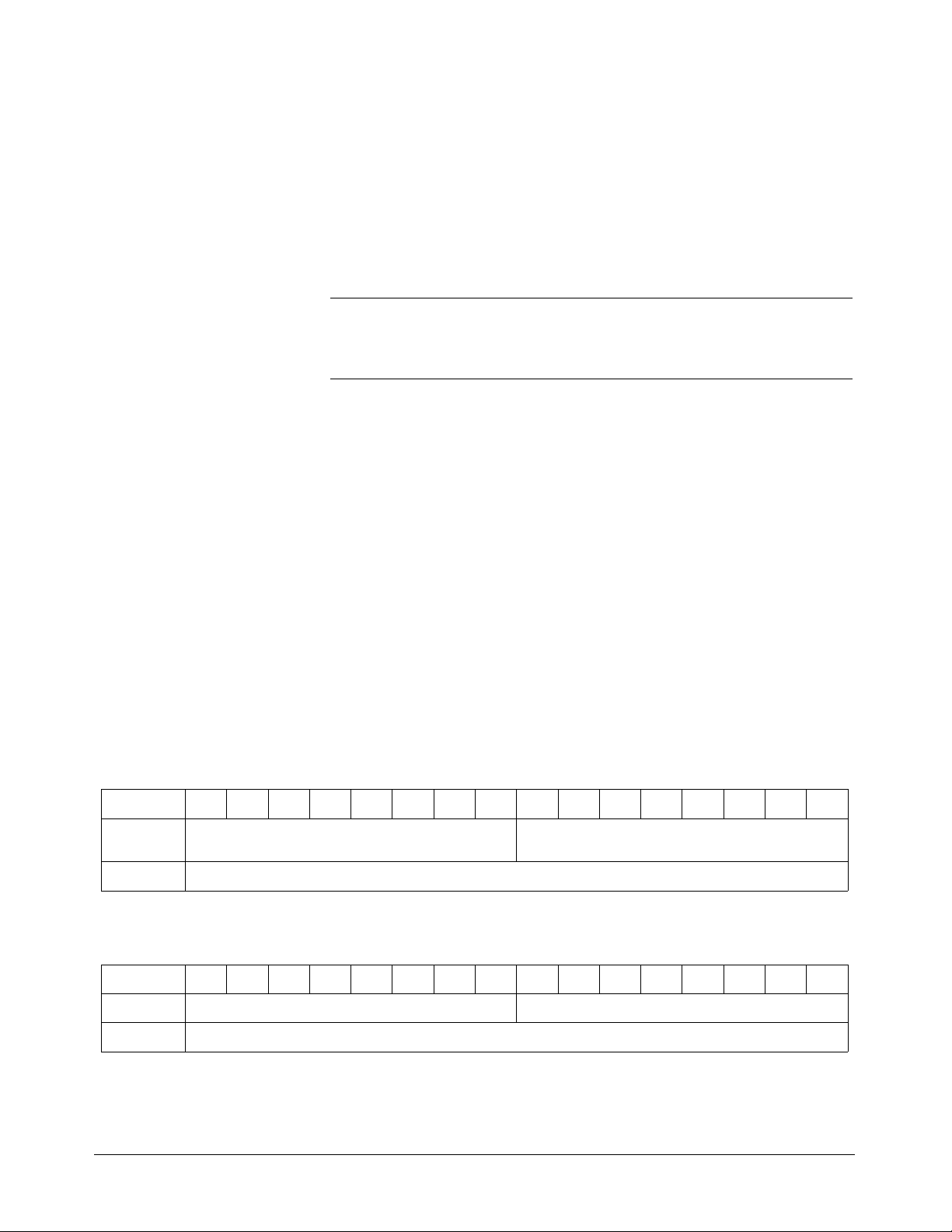
4. Write the selected channel’s Most Significant Byte (MSB) in bits 0-7
(register 10
, 1416, 1816, or 1C16).
16
5. Poll the St at us/Control R egister until C/P RDY is one (1).
6. Write the selected channel’s Least Significant Byte (LSB) in bits 0-7
(register 12
, 1616, 1A16, or 1E16). Writi ng to an LSB Register will
16
cause the corresponding channel to be updated.
Note The output is not changed until the LSB is received. If the MSB has not
changed from the previous entry, you need o nly s end the LSB.
For example, to progra m +100 mVdc on channel 4:
1. Multiply 100 by 3 ( = 300 deci mal, or 12C
). Add this to 800016 to
16
get the output data (= 33068 decimal, 100 0001 0010 1100 binary,
).
16
low byte.
low byte.
) in channel 4 MS B Register
16
) in channel 4 LSB Register
16
16
Command and
Parameter Registers
or 812C
2. Enter MS B (1000 0001 bi nary, 81
1C
16
3. Enter LSB (0010 1100 binary, 2C
1E
16
Seven commands c ontrol e quipment operatio n usin g the 0816 register.
Three of these commands have para met ers used to enter data in the 0A
register. Refer to the register definitions and the following explanation for
Command and Parameter Register information.
Command Register (Write)
Base + 08161514131211109876543210
Write Ignored Null, Cal-on/ off , Calibr at e, Checks um , Zero-all ,
Read Undefined
Restart
Parameter Register (Write)
Base + 0A161514131211109876543210
Write Ignored Calibrate, C hecksum , and Resta rt
Read Undefined
64 HP E1328A Register- Based Pr ogr amming Appendix B
Page 65

The procedure for sending a command is as f ollows:
1. Poll the Status /Co ntro l Register unt il both DON an d RDY are ass erte d (1).
2. Write the Command byte to the Command Register (08
16
command is invalid (and DONE is true again), ER* will be zero (0).
The command will not be executed until all required parameters
(if any) have been received. If the command is CALIBRATE,
CHECKSUM or RESTAR T, enter pa rameters as follows:
3. Poll the Status/Cont r o l Regist er until C/P RDY is asserted (1).
4. Write a Parameter byte to the Parameter Register (0A
16
).
5. Repeat steps 3 and 4 as required to send all parameters.
Note The D/A Converter channel number physical markings and SCPI
co mma nds are nu mbered from 1 to 4, but f or reg ister-based progra mmin g
the channels are numbered 0 to 3, respectively.
Commands referencing higher channel numbers than 3 will be ignored, and the
ER* bit will be set to one (1) after receipt of the final parameter. In the
command formats given, xxx = don’t care, cccc = chann el number from 0 to 3,
= binary, and 16 = hex.
b
). If the
NULL: Resets the ER* bit of the Status/Control Register and terminates
any pendi ng c ommand. The NULL command does not ha ve a par ameter.
Command format is as follows:
0000xxxxb or 0x16.
CAL-OFF: Disables gain and offset adjustment for the indicated channel,
providing greater sp eed and output range, but less accuracy. The CAL-OFF
command does not ha ve a par ameter. Command format is as fol lows:
0010ccccb or 2c16
For example, th e command 001000 00b or 2016 sets channel 1 mode to
non-calibrated (CAL-OFF).
Appendix B HP E1328A Register-Based Programming 65
Page 66

CAL-ON: Enables gain and offset adjustment for the indicated channel,
providing greater accurac y, but less speed and output range. The CAL-ON
command does not ha ve a par ameter. Command format is as fol lows:
0011ccccb or 3c
16
For example, th e command 001100 01b or 3116 sets channel 2 mode to
calibrated (CAL-ON).
CHECKSUM: Checksums the stored adjustment constants for the
specified channel, and sets the E R* bit accordingly. E R * is asserted (low) if
checksum is bad, and deasserted (high) if good. The CHECKSUM
parameter bit (m) is 0 to check current mode constants, and 1 to check
voltage mode c onstants. The state of the D/A Converter modul e’s V/I
jumpers is ign ored. C o mman d for mat (regist er 08
0101ccccb or 5c
16
) is as follows:
16
Parameter forma t ( register 0A16) is as follows ( m is parameter):
0000000mb or 0m
16
For example, the Command 01010010b or 5216 (0816 Register) and
Parameter 00000001
or 01
b
(0A16 Register) performs a checksum on the
16
adjustment constant f or channel 3 voltage.
ZERO-ALL: Writes (uncalibrated) zero to all channels as quickly as
possible. The ZERO-ALL command does not have a parameter. Command
format is as f ollo ws:
10101010b or AA
16
RESTART: This command is used to recover from AC FAIL and IE*
conditions. Command f ormat is as f ollo ws:
11110000
or F0
b
16
Parameter format is as follows (fixed parameter):
11110111b or F7
16
CALIBRATE: Used to change a channel’s stored voltage and/or current
adjust ment constant. The sta te of the channel’s V/I jumpers determines
which constant is entered. These constants ar e used by the D/A Conv erter
to maintain the required output accurac y when in the calibrated mode.
The CALIBRATE command and parameter are used to enter new offset,
gain, and checksum values. These values are calculated from actual channel
output measurements, t hen e ntered into the Parameter Register.
66 HP E1328A Register- Based Pr ogr amming Appendix B
Page 67

Command format (register 0816) is as follows:
0100ccccb or 4c
16
Parameter forma t ( register 0A16) consists of s even bytes as follows:
– Offset high byte
– Offset low byte
– Gain high byt e
– Gain second byte
– Gain third byte
– Gain low byte
– Ch e cksum byte
The procedure to perform an electronic adjustment on a channel is as follows:
1. Configure the s elected channel’s V/I jumpers to vo ltage or curre nt as
required (refer to page 17).
2. Connect the load and a precision multime t er to the selected channel’s
V/I output terminals. Configure the multimeter for voltage or current
as required.
3. Change the selected channel mode to CAL-OFF.
4. Output the value 0000
(minimum) and measure the resulting
16
voltage or current. Record the measured valu e as ym .
5. Output the value 8000
(default or reset) and measure the resulting
16
voltage or current. Record the measured valu e as yo.
6. Output the value FFFF
(maximum) and measure the resulting
16
voltage or current. Record the measured valu e as yp.
7. Calculate the offset (J) and gain (K) constants using the equations
given below. The equations must be calculated using double
precision floating p oint arithmetic. (A samp le program (in C) to
compute the J, K, and checksum (steps 7 to 8) is listed below.) If the
sample program is used, proceed to step 9.
Calculate b
b
o
and b1 as follows:
o
eq
ad −
=
− cq
dp
and b
− ac
ep
=
1
− cq
dp
Appendix B HP E1328A Register-Based Programming 67
Page 68

where:
w = 3.65
ym = me a sured valu e in st ep 4
yo = measur e d value in step 5
yp = measur e d va lue in step 6
a= (ym) + (w)(yo) + (2
p= w+2
c=q= (2
d= (2
15
)(w) + 2
30
)(w) + 232 - 217 + 1
16
- 1
Calculate J and K as follows:
16
- 1)(yp)
k =
J =
2
−bo
32
b1
+
1 −
R
15
1)
15
(2
−1)(b
k
− 2
17
2
where: R= 10.92233 for volts
0.02184467 f or current
K should be rounded to a 32 bit unsigned integer. Use the rounded
value of K to compute J. Round J to the nearest integer and express
in 8-bit two’s complement form.
NOTE: For maximum speed, precompute the actual output data
using the following equation, and operate the HP E1328A in
uncalibrated mode:
k × x
y =
J + x −
32
2
where: x = desired output code (calculated as sh own under “Channel
Output Registers” on page 63) and y = value actuall y s ent to t he
HP E132 8 A.
8. Compute a checksum by adding the 6 bytes representing J and K (on
an 8-bit wide basis) and taking the two’s complement of the result.
(Checksum is defined to be that number whic h causes all seven bytes
to sum to zero in byte-wide arithmetic.)
For example (in h ex), if offset (J) is 0B 7C and gain (K) is 16 F8 F2
1A (as calc ulated in step 6), th en checksum wou ld be 5F.
9. Use the CALIBRATE command and parameter to load J, K and the
checksum into the D/A Converter’s memory.
For example (using hex exa mp le values in step 8), entering the
following calculated offset (J), gain (K), and checksum for channel 4
68 HP E1328A Register- Based Pr ogr amming Appendix B
Page 69

is as follo ws:
00110011b or 3316 (register 0816)
instructs channel 4 to accept the f ol lowing data entries.
The seven parameters (register 0A
0B
is high 8 bits of calculated offset (J).
16
is low 8 bits of calculated offset (J).
7C
16
is high 8 bits of calculated gain (K).
16
16
is second 8 bits of calculated gain (K).
F8
16
is third 8 bits of calculated gain (K).
F2
16
is low 8 bits of calculated gain (K).
1A
16
is calculated check sum.
5F
16
) are entered as follows:
16
10. Change the selected channel mode to CAL-ON.
11. If desired, check that the constants have been loaded correctly by
outputting 8000
and verifyi ng that t he channel output is zero 24
16
hour accuracy for voltage or current ( see Appendix A).
Sample Program The fo llowing is a sampl e program writ ten in C to calculate J, K, a nd
checksu m. “ym, yo, and yp” (from steps 4-6 on page 67) are measured and
entered. Note, t he progr am doe s not pr ompt for the value of w, t he de fault
value of 3.65 is used.
/* This program demonstrates a weighted least-squares approach to determining DAC calibrat io n
constants.
ym = (uncalibrated) negative full-scale output valu e
yp = positive full-scale output
y0 = uncalibrated zero
w = weighting factor for relat i ve import ance of zero
w = 3.65 is the recommended weighting factor
w = 1 yields conventional least-squares algorithm
The DAC characteristic is model ed a s y = b1*x + b0.
The coefficients b1 and b0 are used to calculate the actual calibrat ion constants, J and K. */
dac_line(yp, y0, ym , w, b1, b0)
double yp, y0, ym, w, *b1, *b0;
{
double u[2], M[2] [2] , N[2][2] , d;
u[0] = ym + w * y0 + yp;
u[1] = w * 0x8000 * y0 + 0xFFFF * yp;
M[0][0] = w + 2;
M[0][1] = 0x8000 * w + 0xFFFF;
M[1][0] = M[0] [1] ;
M[1][1] = w * (double)(0x8000) * 0x8000 + (double)(0x FFFF) * 0xFFFF;
d = M[0][0]*M[1][1] - M[0][1]*M[1][0];
N[0][0] = M[1][ 1] / d;
N[0][1] = - M[0][1] / d;
Appendix B HP E1328A Register-Based Programming 69
Page 70

N[1][0] = - M[1][0] / d;
N[1][1] = M[0][ 0] / d;
*b0 = N[0][0]*u[0] + N[0][1]*u[1];
*b1 = N[1][0]*u[0] + N[1][1]*u[1];
return;
}
main()
int i, Jint;
double yp, y0, ym, b1, b0, w, J, K, Rx;
unsigned long Kint, checksum;
char string[81];
w=3.65; /* may be changed if desired */
printf(“\nEnter yp, y0, ym (in Vol ts or Amps)\n”); /* prompt for data */
gets(string);
sscanf(string, "%l f , %lf, %lf",& yp,& y0,& ym) ;
dac_line(yp,y0,ym , w,&b1,&b0); /* find best fit line */
printf(“\nCoef fic ients of best-fit line, using w = %g:\n”,w);
printf(“\tb1 = %g\n”,b1);
printf(“\tb0 = %g\n”,b0);
/* compute cal con stants from best fit line */
if(yp=1) Rx = 10.92233; /* voltage case */
else Rx = .02184467; /* current case */
K = 1.0 - ( Rx /( 0x7fff * b1));
K *= 4.0 * 0x8000 * 0x8000; /* mult by 2^32 */
Kint = K + .5; /* round to integer */
J = -b0/b1 - 0x8000;
J += ((double)Kint)/(4.0*(doubl e)0x 8000) ; /* divisor is 2^17 */
if(J=(double)0.0) Jint = J +.5; /* round to integer */
else Jint = J -.5; /* J is negative */
/* compute an eight bit checksum */
checksum = Jint & 0xff;
checksum += Jint>8 & 0xff;
for(i=0;i<=3;i++) checksum += ( Kint>(i*8) ) & 0xff;
checksum ^= -1; checksum += 1; /* two’s complem ent */
checksum &= 0xff; /* truncate to eight bit s */
printf(“\nCalibr ation constants are as follows for Rx = %g:\n”,Rx);
printf(“\tJ = %04x h\n”,Jint); printf(“\tK = %8lx h\n”,Kint);
printf(“\tchecksum = %02lx h\n”,checksum);
}
70 HP E1328A Register- Based Pr ogr amming Appendix B
Page 71
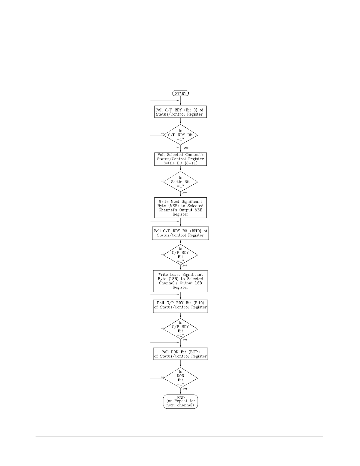
A Register-Based Algorithm
The following algorit hm de scribes th e procedure you would use to program
the registers on the HP E1328A D/A Converter module to output either a
voltage or a current.
Figure B-3. Register-Based Prog rammin g Algori thm
Appendix B HP E1328A Register-Based Programming 71
Page 72

Programming Examples
The examples in this s ection demonstrate how to program the module at the
register level. The programs follow the algorithm described in a previous
section. The examples include:
– Resetting the Module
– Reading the ID, Devic e Type, and Sta tus R egisters
– Outputting a Voltage or Current
System
Configuration
Resettin g the
Module
The following example programs were develop ed with t he mod u le at l ogical
address 72.
– The HP BASIC programs were developed using the HP E1300
mainframe Series B HP IBASIC language.
– The C language programs were deve loped on an HP Vectra PC
(IBM PC compatible) using Borland’s Turbo C++
language, the HP 82335 HP-IB Interface and HP-IB Comma nd
Library. The last C language programming example was developed
on the HP RADI-EPC7 Embedded Contro ller.
The following program res ets the HP E1328 A D/A Co nverter module. The
proc ess is as follows:
1. Write a "2" to the Status/Control Register to set SFI high.
2. Write a "3" to the Status/Control Register to keep the SFI bit high
and set the reset bit.
3. Wait 200 mS.
4. Write a "2" to the Status/Control Register to keep the SFI bit high
and zero the reset bit.
5. Wait 100 mS.
6. Write a "0" to the Status/Control Register.
®
programming
HP IBASIC Vers ion 10 Base_addr = DVAL("1FD200",16) !Logical Address 72.
20 Reg_addr = 04 ! Offset for Status Control Register.
30 ! Write a 2 then a 3 to the Status Register.
40 WRITEIO -9826, Base_addr + Reg_addr; 2
50 WRITEIO -9826, Base_addr + Reg_addr; 3
60 WAIT .2 ! wait 200 mS.
70 WRITEIO -9826, Base_addr + Reg_addr; 2
80 WAIT .1 ! wait 100 mS.
90 WRITEIO -9826, Base_addr + Reg_addr; 0
100 END
72 HP E1328A Register- Based Pr ogr amming Appendix B
Page 73

C Version
/* reset the module */
#include <stdio. h>
#include <chpib.h>
#include <dos.h>
#define LOG_A DDR 72 /* HP E1328A Logical Address */
#define BASE_ADDR (long) ((0x 1F C000) + (64 * LOG_ADDR))
/* function to send valu e s to the Statu s Register */
void send_v al ue (int b a se_address, int data_v alue)
{
float send_data[3], read;
char state[2] = {13,10};
send_data[0] = base_address + 4; /* Stat us Register of fse t */
send_data[1] = 16; /* base 16 */
send_data[2] = data_value; /* data value sent to the regi ster */
IOEOI (7L, 0); IOEOL (7L, “ ”, 0); /* HP-IB library call */
IOOUTPUTS (70900L, “DIAG:POKE ”, 10);/* HP-IB library call */
IOEOI (7L, 1); IOEOL (7L, state,0); /* HP-IB library call */
IOOUTPUTA (70900L, send_data, 3); /* HP-IB library call */
}
main ()
{
return 0;
}
send_value(B ASE_A DDR, 2);
send_value(B ASE_A DDR, 3);
delay (200); /* wait 200 mS (del ay is uni que
to Borland Turbo C++) */
send_value(B ASE_A DDR, 2);
delay (100); /* wait 100 mS */
send_value(B ASE_A DDR, 0);
Appendix B HP E1328A Register-Based Programming 73
Page 74

Reading th e ID,
Device Type, and
The following examples read the ID, D evice Ty pe, and Status/Control
Registers.
Status Registers
HP IBASIC Vers ion 10 !**********************************************************
20 !***** READREG *****
30 !**********************************************************
40 ! OPTION BASE 0 is default.
50 ! Set up arrays to store register name s and addresses.
60 DIM Reg_name$(0:2)[32], Reg_addr(0:2)
70 !
80 ! Read register nam es and addresses into the arrays.
90 READ Reg_name$(*)
100 READ Reg_addr(*)
110 !
120 ! Set base Address variable.
130 Base_addr = DVAL ("1FD200",16)
140 !
150 ! Map the A16 address space.
160 !
170 ! CONTROL 16,25;2 ! used only with V360 Controller.
180 ! Call the subprogram Read_regs.
190 Read_regs(Base_addr, Reg_name$(*),Reg_addr(*))
200 !
210 DATA Identification Register, Device Register, Status Register
220 DATA 00, 02, 04
230 END
240 ! This subprogram reads each register and prints its contents.
250 SUB Read_regs(Base_addr, Reg_name$(*),Reg_addr(*))
260 FOR Number = 0 to 2
270 Register = READIO(-9826,Base_addr + Reg_addr(number))
280 PRINT Reg_name$(num ber); " = "; IVAL$(Register, 16)
290 NEXT Number
300 SUBEND
This program returns:
ID Register =
FFFF
Device Type Register = FF7F
Status/Cont rol Register = (dependent on current st atus , default is FFFF)
74 HP E1328A Register- Based Pr ogr amming Appendix B
Page 75

C Version
#include <stdio. h>
#include <chpib.h>
#include <cfunc.h>
#define LOG_ADDR 72
#define BASE_ADDR (long) ((0x 1F C000) + (64 * LOG_ADDR))
main()
{
int reg_addr;
float send_data[3], read;
char state[2] = {13,10};
send_data[1] = 16;
send_data[2] = 0;
/* Read ID Register */
send_data[0] = BASE_ADDR + 0;
IOEOI (7L, 0); IOEOL (7L, , 0); /* HP-IB library call */
IOOUTPUTS (70900L, “DIAG:PEEK? ”, 11);/* HP-IB library call */
IOEOI (7L, 1); IOEOL (7L, state, 2); /* HP-IB library call */
IOOUTPUTA (70900L, send_data, 2); /* HP-IB library call */
IOENTER(70900L, &read); /* HP-IB library call */
printf(\nIdentification Register = %0x,(int)read);/* print ID Regi ste r */
/* Read Device Type Regi ster */
send_data[0] = BASE_ADDR + 2;
IOEOI (7L, 0); IOEOL (7L, , 0); /* HP-IB library call */
IOOUTPUTS (70900L, “DIAG:PEEK? ”, 11);/* HP-IB library call */
IOEOI (7L, 1); IOEOL (7L, state, 2); /* HP-IB library call */
IOOUTPUTA (70900L, send_data, 2); /* HP-IB library call */
IOENTER(70900L, &read); /* HP-IB library call */
printf(\ nDevice Register = %0x,(int )read) ; /* print Device R egister */
/* Read Status Register */
send_data[0] = BASE_ADDR + 4;
IOEOI (7L, 0); IOEOL (7L, “ ”, 0); /* HP-IB library call */
IOOUTPUTS (70900L, “DIAG:PEEK? ”, 11);/* HP-IB library call */
IOEOI (7L, 1); IOEOL (7L, state, 2); /* HP-IB library call */
IOOUTPUTA (70900L, send_data, 2); /* HP-IB library call */
IOENTER(70900L, &read); /* HP-IB library call */
printf(“\nStatus Register = %0x”,(int)read);/* prin t Status Register */
return o;
}
Appendix B HP E1328A Register-Based Programming 75
Page 76

Outputting a
Voltage or Current
HP IBASIC Vers ion
For specific inform ation on set ting or changi ng the output le vels , s ee the
sections titl ed “Channel Output Regist ers” on page 63 and “A
Register-Based Algorithm” on page 71. Voltage or current mode is jumper
selected on the module; it is not possible to select either the voltage or
current mode b y regist er pr ogra mming. Ensure the proper mode is sel ected
before writing data to the module.
The following examples set the D/A Converter Channel 1 to output
+100mVdc. First determine the output data. The required value is a 16-bit
number in offset binary. FFFF
negativ e full scale, an d 8000
represents positive full scale, 000016 is
16
is zero. Calibrated output modes are
16
arranged to provide "3 counts per 1 mV" resolution.
For our example, to pro gra m 100 mV, multiply 100 by 3 (= 300 decimal, or
). Add this to 800016 to get the output dat a (812 C16). (For negative
12C
16
output valu es, su btr act from 8000
and 2C
is th e LSB. Wr iting to the LS B Register causes the c orrespon ding
16
instead of adding). 8116 is the MSB
16
channel to output the specified voltage or current.
10 Base_addr = DVAL("1FD200",16)
20 Msb_addr = DVAL("10",16) ! Cha nne l 1 MSB Regi ste r offset.
30 Lsb_addr = DVAL("12",16) ! Channel 1 LSB Regist er of fse t .
40 ! Poll Status Register Bit 0 (RDY).
50 REPEAT
60 UNTIL BIT (READIO (-9826, Base_addr + 4),0)
70 ! Verify that Channel settle bit is 1.
80 REPEAT
90 UNTIL BIT (READIO (-9826, Base_addr + 4),8)
100 ! Write the MSB.
110 WRITEIO -9826, Base_addr + Msb_addr; DVAL ("81",16)
120 ! Poll Status Register Bit 0 (RDY).
130 REPEAT
140 UNTIL BIT (READIO (-9826, Base_addr + 4),0)
150 ! Write LSB.
160 WRITEIO -9826, Base_addr + LSB_addr; DVAL("2C",16)
170 ! Poll Status Register Bit 0 (RDY).
180 REPEAT
190 UNTIL BIT (READIO (-9826, Base_addr + 4),0)
200 ! Poll Status Register Bit 7 (DON).
210 REPEAT
220 UNTIL BIT (READIO (-9826, Base_addr + 4),7)
230 END
76 HP E1328A Register- Based Pr ogr amming Appendix B
Page 77

C Version
/* Output a Voltage */
#include <stdio. h>
#include <chpib.h>
#include <dos.h>.h
#define LOG_A DDR 72 /* E1328 Logical Address */
#define BASE_ADDR (long) ((0x 1F C000) + (64 * LOG_ADDR))
float send_data[3], read; /* Output data array */
int msb_addr = 0x10; /* MSB Register address */
int lsb_addr = 0x12; /* LSB Register address */
char state[2] = {13,10}; /* CR/LF for data */
/*Function to poll Status Register to make certain channel is ready */
void poll_status_register (base_addre ss)
{
long bit_number;
float send_data[3], read;
send_data[0] = base_address + 4; /* Status Register address */
send_data[1] = 16; /* hex base */
send_data[2] = 0; /* no value because reading the
register */
IOEOI (7L, 0); IOEOL (7L, “ ”, 0); /* HP-IB library call */
IOOUTPUTS (70900L, “DIAG:PEEK? ”, 11); /* HP-IB library call */
IOEOI(7L,0); IOEOL(7L, “ ”,0); /* HP-IB library ca ll */
IOOUTPUTA (70900L, send_data,2); /* HP-IB library call */
while (bit_number != 0x0101) /* wait until bits 0 and 8
(channel 1) are ready */
{
IOENTER(70900L, &read); /* HP-IB library ca ll */
bit_number = ((long)(read));
}
}
main ()
{
/* Poll Status Register to ensure channel ready */
poll_status_register( BASE _ADDR);
/* Send Channel MSB */
send_data[0] = BASE_ADDR + msb_addr;/* set MSB address */
send_data[2] = 0x81; /* MSB data */
Appendix B HP E1328A Register-Based Programming 77
Page 78

IOEOI (7L, 0); IOEOL (7L, “ ”, 0); /* HP-IB library call */
IOOUTPUTS (70900L, “DIAG:POKE ”, 10);/* HP-IB library call */
IOEOI (7L, 1); IOEOL (7L, state,0); /* HP-IB library ca ll */
IOOUTPUTA (70900L, send_data, 3); /* HP-IB library ca ll */
/* Poll Status Register to ensure channel ready */
poll_status_register( BASE _ADDR);
/* Send Channel LSB */
send_data[0] = BASE_ADDR + lsb_addr;/* set LSB address */
send_data[2] = 0x2C; /* LSB data */
IOEOI (7L, 0); IOEOL (7L, “ ”, 0); /* HP-IB library call */
IOOUTPUTS (70900L, “DIAG:POKE ”, 10);/* HP-IB library call */
IOEOI (7L, 1); IOEOL (7L, state,0); /* HP-IB library ca ll */
IOOUTPUTA (70900L, send_data, 3); /* HP-IB library ca ll */
return 0;
}
78 HP E1328A Register- Based Pr ogr amming Appendix B
Page 79

Using an Embedded
HP RADI-EPC7
Computer
/* E1328_VO.CPP - This program sets D/A Converter to output -2.00V */
/* on channel 1. The program can also be used to set the output vol tage or */
/* output current on any channel. Note that the channel mode (voltage or */
/* current) must be set using the jumpers on the HP E1328A module. */
#include <sicl.h>
#include <stdio. h>
#include <stdlib. h>
#include <conio.h>
#include <dos.h>
/* define macro s to monitor D/A stat us in the Status Register */
#define READY (iwpeek((unsigned short *)(base_addr + 0x04)) & 0x01)
#define DONE ((iwpeek((u n signed short *)(base_addr + 0x04)) & 0x81) == 0x81)
#define SETTLE1 (iwpeek((u nsigned short *)(base_addr + 0x04)) & 0x100)
#define SETTLE2 (iwpeek((u nsigned short *)(base_addr + 0x04)) & 0x200)
#define SETTLE3 (iwpeek((u nsigned short *)(base_addr + 0x04)) & 0x400)
#define SETTLE4 (iwpeek((u nsigned short *)(base_addr + 0x04)) & 0x800)
#define PASS_FAIL (iwpeek( (unsigned short *)(ba se_addr + 0X04)) & 0x04)
The following C language program was developed on the HP RADI-EPC7
embedded computer using the Standard Instrument Control Library (SICL) for
DOS. As listed, the program sets channel 1 to output -2.00V. The program
can be used to set the output voltage or current on any DAC channel.
/* Function prototypes */
void setup_dtoa(char *base_addr, int mode, int channel, float level);
void reset_dtoa(char *base_addr);
void main(voi d)
{
char *base_addr;
/* create and open a device se ssion */
INST e1328a;
e1328a = iopen("vxi,72");
/* map the HP E1328A registers into user memory space */
base_addr = imap(e1328a, I_MAP_VXIDEV, 0, 1, NULL);
/* function call to reset the D/A conv er ter */
reset_dtoa(base_addr);
/* function call to set up the D/A converter; send base address, */
/* mode (voltage = 1, any other number = current), channel (1-4), */
/* and level (in volts or amps) */
setup_dtoa(base_addr, 1, 1, -2.00); /* outputs -2.0V on channel 1 */
/* close session */
iclose(e1328a);
}
Appendix B HP E1328A Register-Based Programming 79
Page 80

/*********************************************************************************/
void setup_dtoa(char *base_addr, int mode, int channel, float level)
{
/* This function sets up the D/A converter to output voltages or currents */
/* on the specified channels. */
unsigned short level_word = 0, msbyte = 0, lsbyte = 0;
/* conv ert voltage or current level to binary number */
if (mode == 1) /* convert voltage */
{
level_word = (unsigned short)(level * 3000) + 0x8000;
msbyte = level_word >> 8;
lsbyte = level_word & 0xFF;
}
else /* conver t current */
{
level_word = (unsigned short)(level * 1500000) + 0x8000;
msbyte = level_word >> 8;
lsbyte = level_word & 0xFF;
}
/* wait for the D/A ready bit and the channel’s settle bit = 1, */
/* and then write msbyte of voltage */
switch (channel)
{
case 1: while(!RE ADY); /* channel 1 */
while(!SET TLE 1);
iwpoke((unsigned short *)(base_addr + 0x10),msbyte);
/* wait for D/A ready bit = 1, and then write lsbyte of voltage */
while (!READY);
iwpoke((unsigned short *)(base_addr + 0x12),lsbyte);
break;
case 2: while(!RE ADY); /* channel 2 */
while(!SET TLE 2);
iwpoke((unsigned short *)(base_addr + 0x14),msbyte);
/* wait for D/A ready bit = 1, and then write lsbyte of voltage */
while (!READY);
iwpoke((unsigned short *)(base_addr + 0x16),lsbyte);
break;
case 3: while(!RE ADY); /* channel 3 */
while(!SET TLE 3);
iwpoke((unsigned short *)(base_addr + 0x18),msbyte);
/* wait for D/A ready bit = 1, and then write lsbyte of voltage */
while (!READY);
iwpoke((unsigned short *)(base_addr + 0x1A),lsbyte);
break;
80 HP E1328A Register- Based Pr ogr amming Appendix B
Page 81

case 4: while(!RE ADY); /* channel 4 */
while(!SET TLE 4);
iwpoke((unsigned short *)(base_addr + 0x1C),msbyte);
/* wait for D/A ready bit = 1, and then write lsbyte of voltage */
while(!READY);
iwpoke((unsigned short *)(base_addr + 0x1E),lsbyte);
break;
default: exit(EXIT_FAILURE);
break;
}
/* wait for command to complete before setting next output */
while(!READY);
while(!DONE); }
/*********************************************************************************/
void reset_dtoa(char *base_addr)
{
/* This function resets the D/A converter by disabl ing the Stat u s/Control */
/* Register ’SYSFAIL’ bit (bit 1), by writing a ’1’ to the soft reset bit */
/* (bit 0), and then by writing a ’0’ to bit 0. After the reset, the ’SYS FAIL’*/
/* bit is re-enabled. */
iwpoke((unsigned short *)(base_addr + 0x04),2); /* disable ’SYSFAIL’ */
iwpoke((unsigned short *)(base_addr + 0x04),3) ;
delay (200); /* Borland C++ function */
iwpoke((unsigned short *)(base_addr + 0x04),2); /* turn off reset */
while (!PASS_F AIL) ; /* wait for the reset to compl et e */
iwpoke((unsigned short *)(base_addr + 0x04),0); /* enable ’SYSFAIL’ */
}
Appendix B HP E1328A Register-Based Programming 81
Page 82

Notes
82 HP E1328A Register- Based Pr ogr amming Appendix B
Page 83

Appendix C
HP E1328A Error Messages
Table C-1 lis ts the error mess ages assoc iated with th e 4-Channe l D/A
Converter module program me d by SCPI. See the app ropriate mainfr ame
manual for a complete list of error messages.
Table C-1. 4-Channel D/A Converter Error Messages
No. Title Potential Cause(s)
–350 Too many errors Th e error queue is full as more tha n 30 er rors
–330 Self -t es t F a ilure Module malfun ct ion.
–240 Hardware Failure Module malfunct ion.
–221 Jumper Settings Channel’s V/I jumper in incorrect position.
+2801 Channel 1 current
checksum error
+2802 Channel 2 current
checksum error
+2803 Channel 3 current
checksum error
+2804 Channel 4 current
checksum error
+2805 Channel 1 voltage
checksum error
+2806 Channel 2 voltage
checksum error
+2807 Channel 3 voltage
checksum error
+2808 Channel 4 voltage
checksum error
have occurred.
Channel 1 stored adjustment
constan t (current) is corr upt ed .
Channel 2 stored adjustment
constan t (current) is corr upt ed .
Channel 3 stored adjustment
constan t (current) is corr upt ed .
Channel 4 stored adjustment
constan t (current) is corr upt ed .
Channel 1 stored adjustment
constan t (voltag e) is corrupted.
Channel 2 stored adjustment
constan t (voltag e) is corrupted.
Channel 3 stored adjustment
constan t (voltag e) is corrupted.
Channel 4 stored adjustment
constan t (voltag e) is corrupted.
Appendix C HP E1328A Error Messages 83
Page 84

Notes
84 HP E1328A Error Messages Appendix C
Page 85

Index
HP E1328A D/A Converter Module User’s Manual
B
*CLS, 49–50
*ESE, 50
*ESE ?, 50
*ESR?, 50
*IDN?, 50
*OPC, 50
*OPC?, 50
*RCL, 50
*RST, 19, 50
*SAV, 50
*SRE, 50
*SRE?, 50
*STB?, 50
*TST ?, 50
*WAI, 50
A
A16 Address Space
descrip tion, 55–57
inside command module, 57
inside mainfram e, 57
outside command module, 56
Abbreviated SCPI Command s, 40
AC FAIL Line, 12
Accessing the Registers, 58
Accuracy, 53
Address
base address, 56–57
inside the command module, 57
logica l, 16, 55, 5 7
outside the command modul e, 56
registers, 55–57
secondary HP-IB, 12
Adjustment
electronic, 34–35, 67–70
electron ic cu rren t , 26–28, 42
electronic vol tage, 20–22 , 44
Algorithm, regist er -based, 71
Base Address, 56–57
Block Diagram , 11
Boolean Command Par ameters, 40
Bytes
checksum bytes, 67
gain bytes, 67
least significant byte (LSB), 59, 63–64
most significant byte (MSB), 59, 63–64
offset b ytes, 67
C
Calibrated Mode
disabling, 43
enabling, 43
output accuracy, 12
output current, exampl e, 29
output volta ge, e xa m ple, 23–25
output v olta ge, ra ng e, 11
output voltage, ra ng e expand ing , 24–25
query, 43
CALibration Su bsystem, 42–44
CALibration:CURRent, 19, 42
CALibration:STATe, 19, 43
CALibration:STATe?, 43
CALibration:VOLTage, 19, 44
CAUTIONS, 15
Certification, 5
Changing
output level, 63
Channel
calibrated mode, 43
electrically isolated, 12
electronic ad justm en t, 67–70
measurement data, entering, 42, 44
mode register, 63
monitoring, 45–46
output current, 27–30, 36
output current, expanding ra nge, 12, 29–30
output current, query, 47
output current, selecting, 17, 47
output current, shor t circui t protecti on, 12
HP E1328A D/A Converter Module User’s Manual Index 85
Page 86

output current, specified channel, 47
output LSB registers, 63–64
output MSB registers, 63–64
output regist er s, 63 –64
output v olta ge, 23 –25, 32
output voltage, expa nd ing range, 12 , 24 –25
output v olta ge, qu ery, 48
output voltage, selecting, 17, 48
output v oltage, sh or t circuit prot ection, 12
output voltage, specified channel, 48
query cali bra ted m o de, 43
query outpu t, 46
query V/I jumper, 48
specifying, 13
stored current c onsta nts, upd atin g, 26
stored v oltag e constants, up da ti ng, 20
Checksum
bytes, 67
calculating, 69–70
Clearing Error Queue, 49
*CLS, 49–50
Command M odule
A16 address space inside, 57
A16 address spac e outside, 56
Command Re ference, 39 –52
CALibration subsystem, 42–44
*CLS, 49–50
DISPlay subsystem, 45–46
*ESE, 5 0
*ESE?, 50
*ESR?, 50
*IDN?, 50
*OPC, 50
*OPC?, 50
*RCL, 50
*RS T, 19, 50
*SAV, 50
[SOURce:] subsystem, 47–48
*SRE, 50
*SRE?, 50
*STB?, 50
SYSTem subs ystem, 49
*TST?, 50
*WAI, 50
Command Register , 64–69
Commands
CALibration subsystem, 42–44
*CLS, 49–50
Common (*) Command s, 50
common format, 39
DISPlay subsystem, 45–46
*ESE, 5 0
*ESE?, 50
*ESR?, 50
*IDN?, 50
implied SCPI comm ands, 13
in square brackets, 13
linking, 41
*OPC, 50
*OPC?, 50
operation commands, 31
query, 37
quick reference, 50–51
quick reference, IEEE common commands, 50
quick referen ce, SCPI commands, 51
*RCL, 50
*RS T, 19, 50
*SAV, 50
SCPI format, 39–40
selecting SCPI c ommands, 13
[SOURce:] subsystem, 47–48
*SRE, 50
*SRE?, 50
*STB?, 50
SYSTem subs ystem, 49
*TST?, 50
types, 39
used in chapter 3, 19
*WAI, 50
Comment Sheet, reader, 9
Common (*) Commands, 50
*CLS, 49–50
*ESE, 5 0
*ESE?, 50
*ESR?, 50
format, 39
*IDN?, 50
linking, 41
*OPC, 50
*OPC?, 50
quick reference, 50
*RCL, 50
*RS T, 19, 50
*SAV, 50
*SRE, 50
*SRE?, 50
*STB?, 50
*TST?, 50
*WAI, 50
Common Mode Noise, 53
Compliance
current, 32
voltage, 36
Configuring, 15–18
Conformity, declaration, 7
Connecting
86 HP E1328A D/A Converter Module User’s Manual Index
Page 87

field wiring, 18
sense terminals, 18
Current
adjustment, electronic, 26–28, 42
calibrated mode, ou tpu t example, 29
DC specifications, 53
non-calibrat ed mode, ou tpu t example, 29–30
output, 27 –30, 36, 76–81
output, c ompl ianc e v oltage, 36
output, expand ing ran ge, 12
output, queryin g, 47
output, rang e, expanding, 29–30
output, regi ster - based algorithm, 71
output, selecting, 17, 47
output, short cir cuit protect i on, 12
output, using embedded computer s, 79–81
D
D/A Converter
commands, 19, 39–52
operation commands, 31
query c omm an ds, 37
specifications, 53–54
Declarati on of Conformit y, 7
Descrip ti on, 11
registers, 60–69
Device Type Register, 60
reading the, 74–75
Differential Ripple and Noise, 53
Disabling
calibrated mode, 43
monitor mode, 46
DISPlay Subsystem, 45–46
DISPlay:MONitor: C HANne l , 45
DISPlay:MONitor:CHANnel?, 46
DISPlay:MONitor[ :ST AT e] , 46
DISPlay:MONitor: ST Rin g?, 46
Documentati on Histor y, 6
E
Electronic
adjustment, 34
adjustment, and lea d resistan ce, 35
adjustment, procedure for, 67–70
current adjustment, 26–28, 42
voltage adjustm ent, 20–22, 44
Embedded Computers, using , 79–81
Enabling
calibrated mode, 43
channel moni toring , 45
monitor mode, 46
non-calibrated mode, 43
Error
messages, 83–84
queue, 49
*ESE, 50
*ESE ?, 50
*ESR?, 50
Example
current output in calibrated mode, 29
current output in non-cali brated mode, 29 –30
See als o Prog ra m Exa m ples
voltage output in calibra ted m ode, 23–25
Expandi ng
output current range, 29–30
output v oltage r an ge, 12 , 24–25
F
Field Wiring, 18
Fixed Voltag e Sources, 34
G
Gain
bytes, 67
constants, calculating, 67–70
General Description, 11
Getting Started, 11–14
H
HP-IB Secondary Address, 12
I
ID Register, 60
reading the, 74–75
*IDN?, 50
IEEE-488. 2 Common Comma nd s
See Common (*) C omma nds
Implied SCPI Comma nds, 13, 40
Instrument D e fini tion, 12
Isolated Chann el s, 12
Isolation, 54
J
Jumper
V/I, query configuration, 48
V/I, setting, 17
HP E1328A D/A Converter Module User’s Manual Index 87
Page 88

L
N
LADDR, 16
Lead Resista nce, 34 –35
and electron ic adjust m en t, 35
maximum, 33
Least Significant Byte (LSB), 59, 63–64
Load
connecting output terminals t o, 23– 25, 27–30
connecting sense term inal s to, 24–25
Logical Address
factory setti ng, 16, 55, 57
setting, 16
LSB Registers, 63–64
M
Mainframe
A16 address space, 57
AC FAIL line, 12
displaying c ommand s, 45–46
Manufacturer ID Register
See ID Register
Map of Register s, 59
Maximum
errors in error queue, 49
lead resistance, 33
short circuit cur ren t, 36
voltage, 15
wiring size (AWG), 18, 54
Measurement
enteri n g cur rent data , 42
entering vol tage data, 44
Mode of Operation, settin g, 43
Module
block diagram, 11
confi guring t h e, 1 5 – 18
descrip tion, 11
programming, 13
resetting, 72– 73
specifications, 53–54
understa nding th e, 31–38
using the, 19–3 0
V/I jumper setting, 17
Monitorin g
channels, 45–46
mode, 46
Most Significant Byt e (MSB), 59, 63–64
MSB Registers, 63–64
Multimeter
electronic curren t adjustment, 27–28
See als o Voltmeter
Non-Calibra ted M ode
electronic curren t adjustment, 26
electronic vol tage ad justm en t, 20
enabling, 43
output current, example, 29–30
output curren t, ra nge expanding, 29–30
output v olta ge, ra ng e, 11
query, 43
Numeric Comm and Pa ramet er s, 40
O
Offset
bytes, 67
constants, calculating, 67–70
One Channel
current output, 27–29
voltage output, 23
voltage output, with rem ot e sensi ng, 24
*OPC, 50
*OPC?, 50
Output Current, 27–30, 36, 76–81
compliance voltage, 36
expanding output range, 12
querying, 47
range, expanding, 29–30
register-based algor it hm, 71
selecti ng , 17, 47
short circuit protection, 12
specifications, 53
using em bed d ed comp u ter s, 79–8 1
Output Level, changing/ setting, 63
Outp u t Termi na ls
connecting, load to, 23–25, 27–30
Output Voltag e, 23–25, 32, 76–81
accuracy, calibrated mode, 12
compliance current, 32
expanding output range, 12
querying, 48
range, calibrated mode, 11
range, expanding, 12, 24–25
range, non-calibrated mode, 11
register-based algor it hm, 71
remote sense mode, 33
selecti ng , 17, 48
short circuit protection, 12
using em bed d ed comp u ter s, 79–8 1
88 HP E1328A D/A Converter Module User’s Manual Index
Page 89

P
Parameters
boolean, 40
defined, 40
discrete, 40
numeric, 40
optiona l, 40
register, 64–69
SCPI commands, 40
Power Requirements, 54
Program Exam ples, 72–81
calculating checksum, 69–70
calculati ng gai n con sta nts, 69–70
calculating offset constants, 69–7 0
determining calibration constants, 69–70
electronic curren t adjustment, using exter nal
multimeter, 27–28
electron ic vol tag e ad just m en t, using s ystem voltmeter ,
21–22
See als o Example
expandi ng cur ren t out put ran ge, 29 –30
expanding voltage out put range, 24–25
outputting volta ge or curr en t, 76–8 1
reading registers, 74–75
register-based, 72–81
resetting the mod ule, 72–7 3
using em bed d ed comp u ter s, 79–8 1
Programmi ng
register-based, 55–82
Programmi ng the D/A Conver ter , 13
Q
Query
channel output , 46
commands, 37
current output, 47
error queue, 49
mode of operation, 43
monitored channe l , 46
V/I jumper confi gura t i on, 48
voltage output, 48
Querying the D/A C onverter , 37
Quick Ref eren ce
common (*) commands, 50
SCPI commands, 51
R
Range, 53
*RCL, 50
Read Registers
channel mode register , 63
device type register , 60, 74–75
ID register, 60, 74–75
status/control register, 60–62, 74–75
Reader Comment Sheet, 9
Register-Bas ed Progr a m ming, 55– 82
accessing registers, 58
addressing the regi ster s, 55–57
algorithm, 71
base address, 56–57
outputting volta ge or curr en t, 76–8 1
programming examp les, 72–81
reading registers, 74–75
register de finiti ons, 59
register descriptions , 60–69
register offset , 58
resetting the mod ule, 72–7 3
using em bed d ed comp u ter s, 79–8 1
Registers
accessing, 58
addressing, 55–57
channel mode register , 63
channel output regist ers, 63–64
command regi ster , 64– 69
definitions, 59
descrip tions, 60–69
device type register , 60, 74–75
ID register, 60, 74–75
LSB registers, 63–64
map, 5 9
MSB registers, 63–64
offset, 58
parameter register, 64–69
status/co ntr ol register, 60–62, 74–75
Remote Sensin g, 24–25, 33
max imu m lead re sis t an ce, 33
Reset Conditions, 19
Resetting the Module, 72–73
Resolution, 53
*RST, 19, 50
S
Safety Warnings, 6, 15
*SAV, 50
SCPI Commands
abbr eviated, 40
CALibration subsystem, 42–44
command separator, 40
DISPlay subsystem, 45–46
format, 39–40
implied, 13, 40
HP E1328A D/A Converter Module User’s Manual Index 89
Page 90

linking, 41
operation commands, 31
param et ers, 40
quick reference, 51
referenc e, 39– 52
selecting, 13
short, 40
[SOURce:] subsystem, 47–48
SYSTem subsystem, 49
used in chapter 3, 19
used to query, 37
Secondary HP-IB Addr ess, 12
Selecting
current output, 47
monitor channel val ues, 45
monitor mode, 46
SCPI commands, 13
voltage output, 17, 48
Sense Terminals
connecting, 18
connecting, load to, 24–25
Series Voltage S ources, 34
Setting
logical address switch, 16
mode of operation, 43
output level, 63
V/I jumper , 17
Settling Time, 54
Shock Hazard, 15
Short Circuit Protect i on, 12
Short SCPI Commands, 40
[SOURce:] Subsystem, 47–48
[SOURce:]CURRent, 19, 47
[SOURce:]CURRent?, 47
[SOURce:]FUNCtion?, 48
[SOURce:]VOLTage, 19, 48
[SOURce:]VOLTage?, 48
Specifications, 53–54
Specifying
channels, 13
Square Brackets, 13
*SRE, 50
*SRE?, 50
Static Electricity, 15
Status Bit Pre cedenc e, 61–62
Status/C ont rol R egister, 60–62
reading the, 74–75
*STB?, 50
Stored Current C onsta nts, up dati ng, 26
Stored Voltage Const an ts, upda ting , 20
Subsystems (SCPI Commands)
CALibration, 42–44
DISPlay, 45–46
[SOURce:], 47–48
SYSTem, 49
Switches, logica l address, 16
SYSTem Subs ystem, 49
SYSTem:ERRor?, 49
System V oltmeter
electronic vol tage ad justm en t, 21–22
T
Temperat ure C oe fficient , 53
Terminals
output, c onnec t ing load to, 23 –25, 27–30
sense, connecting, 18
*TST ?, 50
Two Channel
current output, 29–30
current output, non-calibrated mode, 29–30
voltage output , wi th remote sensing, 24–25
U
Understa ndi ng the HP E1328 A, 31 –38
Updating
stored current c onsta nts, 26
stored voltage constants, 20
Using
embedded c omputers, 79–81
the HP E1328A, 19–30
V
V/I Jumper
query configura ti on, 48
setting, 17
Voltage
adjustment, electronic, 20–22, 44
calibrated mode, outpu t examp le, 23–25
calibrated mode, ou tpu t range, 11
DC specifications, 53
maximum allowed, 15
non-calibrat ed mode, ou tpu t range, 11
output, 23 –25, 32, 76–81
output, ac curacy , cali bra ted mode, 12
output, compliance current, 32
output, queryin g, 48
output, rang e, expanding, 12, 24– 25
output, regi ster - based algorithm, 71
output, remote sense mode, 33
output, selecting, 17, 48
output, short cir cuit protect i on, 12
output, specified channel, 48
output, using embedded computer s, 79–81
90 HP E1328A D/A Converter Module User’s Manual Index
Page 91

sources, in series, 34
Voltmeter
electronic vol tage ad justm en t, 21–22
See als o Mul ti meter
W
*WAI, 50
WARNINGS, 6, 15
Warrant y, 5
Wiring
guidelines, 18
maximum gau ge, 18 , 54
Write Registers
channel output regist ers, 63–64
command regi ster , 64– 69
parameter register, 64–69
status/co ntr ol register, 60–62
HP E1328A D/A Converter Module User’s Manual Index 91
 Loading...