

Page 1

Installation Note
11884D 6 GHz Operation Upgrade Kit for
the 8752C Network Analyzer
Part Number: 08752-90145
Printed in USA
August 2001
Supersedes June 1995
© Copyright 1995, 2001 Agilent Technologies, Inc
Page 2

Notice.
The information contained in this do cument is sub ject to change without notice
AgilentTechnologies makes no warrantyofany kind with regard to this material, including
but not limited to, the implied warranties of merchantability and tness for a particular
purpose. AgilentTechnologies shall not be liable for errors contained herein or for incidental
or consequential damages in connection with the furnishing, performance or use of this
material.
c
Copyright 1995, 2001 AgilentTechnologies, Inc
All Rights Reserved. Reproduction, adaptation, or translation without prior written
permission is prohibited, except as allowed under the copyrightlaws.
1400 FountaingroveParkway, Santa Rosa, CA 95403-1799, USA
2
Page 3
Product Affected:
8752C Network Analyzer
To Be Performed By:
Purpose
The 11884D 6 GHz upgrade kit provides the 8752C network analyzer with optional 6 GHz
operation. The upgrade kit is keyed to the serial number of an individual network analyzer.
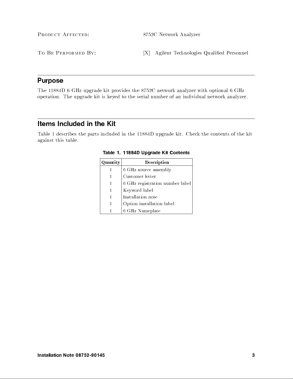
Items Included in the Kit
Table 1 describes the parts included in the 11884D upgrade kit. Check the contents of the kit
against this table.
Table 1. 11884D Upgrade Kit Contents
Quantity Description
1 6 GHz source assembly
1 Customer letter
1 6 GHz registration number label
1 Keyword label
1 Installation note
1 Option installation lab el
1 6 GHz Nameplate
[X] AgilentTechnologies Qualied Personnel
Installation Note 08752-90145 3
Page 4
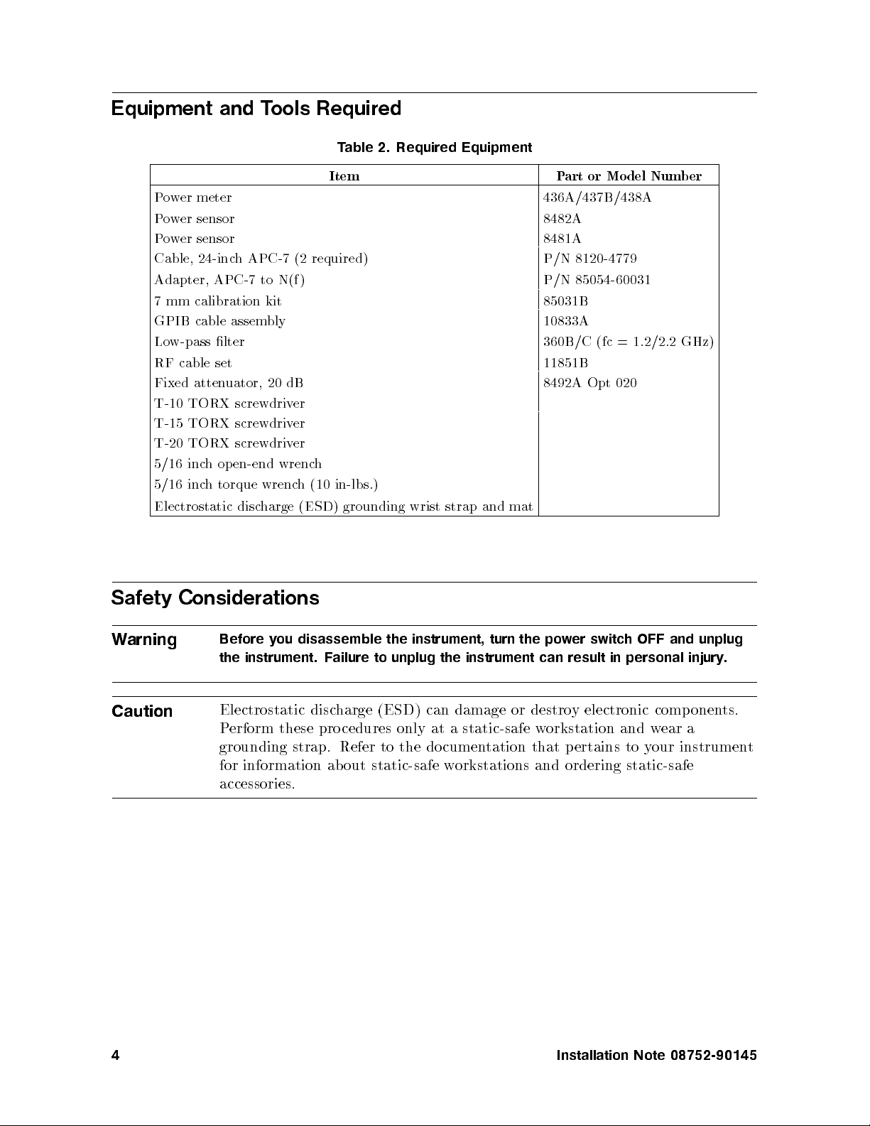
Equipment and Tools Required
Table 2. Required Equipment
Item Part or Model Number
Power meter 436A/437B/438A
Power sensor 8482A
Power sensor 8481A
Cable, 24-inch APC-7 (2 required) P/N 8120-4779
Adapter, APC-7 to N(f ) P/N 85054-60031
7 mm calibration kit 85031B
GPIB cable assembly 10833A
Low-pass lter 360B/C (fc = 1.2/2.2 GHz)
RF cable set 11851B
Fixed attenuator, 20 dB 8492A Opt 020
T-10 TORX screwdriver
T-15 TORX screwdriver
T-20 TORX screwdriver
5/16 inch op en-end wrench
5/16 inch torque wrench (10 in-lbs.)
Electrostatic discharge (ESD) grounding wrist strap and mat
Safety Considerations
Warning
Before you disassemble the instrument, turn the power switch OFF and unplug
the instrument. Failure to unplug the instrument can result in personal injury
Caution
Electrostatic discharge (ESD) can damage or destroy electronic comp onents.
Perform these procedures only at a static-safe workstation and wear a
grounding strap. Refer to the do cumentation that pertains to your instrument
for information ab out static-safe workstations and ordering static-safe
accessories.
.
4 Installation Note 08752-90145
Page 5

Installation Procedure for the 8752C
Verify the Serial Number
Refer to the keyword lab el in the box below. Verify that the analyzer's serial number matches
the serial number below. This keyword will not work on any other analyzer. If the serial
numbers do not match, contact your nearest AgilentTechnologies sales and service oce for
assistance.
Keyword Label
Installation Note 08752-90145 5
Page 6
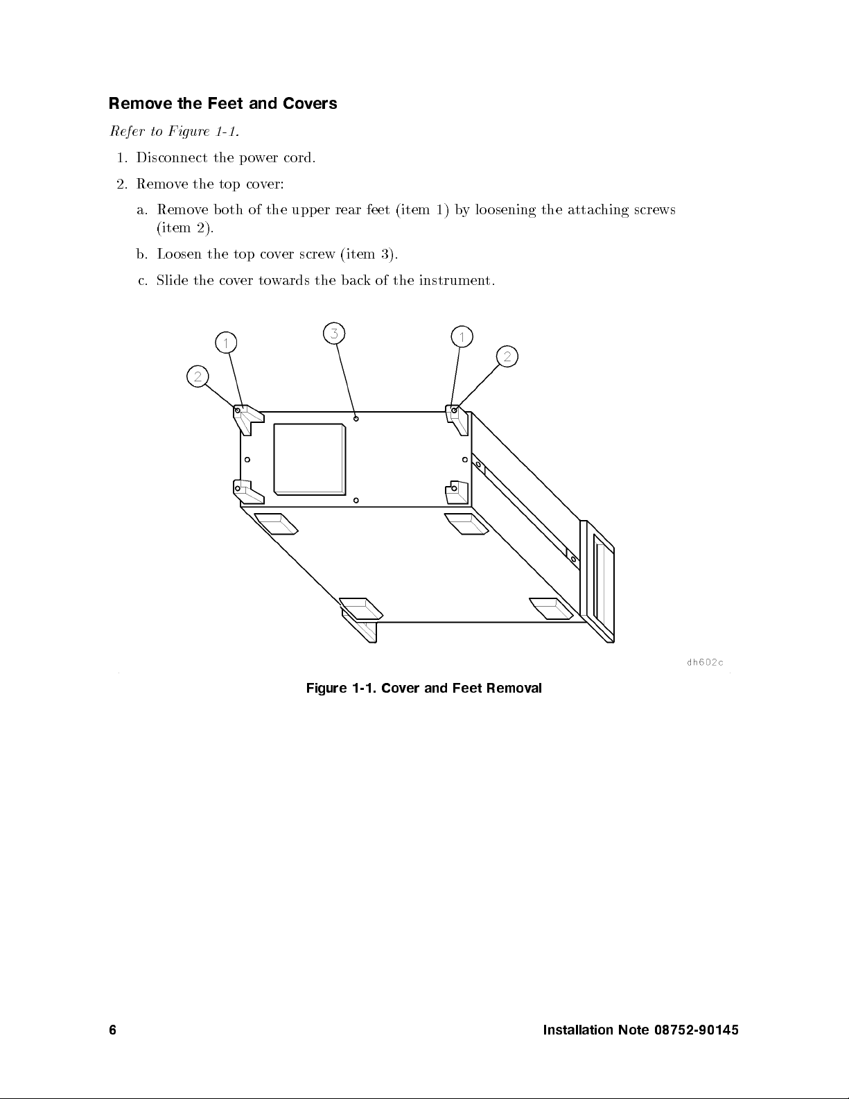
Remove the Feet and Covers
Refer to Figure 1-1.
1. Disconnect the power cord.
2. Remove the top cover:
a. Remove both of the upper rear feet (item 1) by lo osening the attaching screws
(item 2).
b. Loosen the top cover screw (item 3).
c. Slide the cover towards the back of the instrument.
Figure 1-1. Cover and Feet Removal
6 Installation Note 08752-90145
Page 7
Remove the 3 GHz Source Assembly
Refer to Figure 1-2.
3. Remove the source bracket (item 4).
4. Disconnect the two semi-rigid cables (W1 and W24).
5. Lift the two retention clips (item 5) at the front and rear of the source module to an
upright position.
6. The source is seated in a motherboard edge connector. Hold the two lo ose semi-rigid
cables (W1 and W24) to the right and gently pull up on the source bracket handle (item
6) to lift the source assembly out of the instrument.
Replace the Source
Refer to Figure 1-2.
7. Slide the edges of the sheet metal partition (item 7) of the 6 GHz source assembly into the
guides at the front and back of the source compartment.
8. Press down on the assembly to ensure that it is well seated in the motherb oard connector.
9. Push down the retention clips.
10. Reconnect the two semi-rigid cables (W1 and W24) to the source assem
connections to 10 in-lbs.
11. Replace the source bracket.
bly.Torque these
Installation Note 08752-90145 7
Page 8

Figure 1-2. A3 Source Assembly Removal
8 Installation Note 08752-90145
Page 9
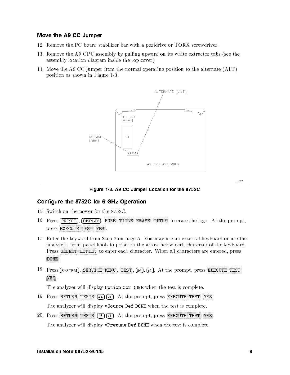
Move the A9 CC Jumper
12. Remove the PC board stabilizer bar with a pozidrive or TORX screwdriver.
13. Remove the A9 CPU assembly by pulling upward on its white extractor tabs (see the
assembly location diagram inside the top cover).
14. Move the A9 CC jumper from the normal op erating position to the alternate (ALT)
position as shown in Figure 1-3.
Figure 1-3. A9 CC Jumper Location for the 8752C
Configure the 8752C for 6 GHz Operation
15. Switch on the p ower for the 8752C.
16.
Press
4
PRESET
NNNNNNNNNNNNNNNNNNNNNNNNNNNNNNNNNNNNNN
press
EXECUTE TEST
5,4
DISPLAY
5
,
NNNNNNNNNNN
YES
NNNNNNNNNNNNNN
MORE
.
NNNNNNNNNNNNNNNNN
TITLE
NNNNNNNNNNNNNNNNN
ERASE
NNNNNNNNNNNNNNNNN
TITLE
to erase the logo. At the prompt,
17. Enter the keyword from Step 2 on page 5. You may use an external keyboard or use the
analyzer's front panel knob to poisition the arrow below eachcharacter of the keyboard.
NNNNNNNNNNNNNNNNNNNNNNNNNNNNNNNNNNNNNNNNN
Press
NNNNNNNNNNNNNN
SELECT LETTER
to enter eachcharacter. When all characters are entered, press
DONE
18.
Press
NNNNNNNNNNN
YES
4
SYSTEM
.
5
,
The analyzer will display
19.
Press
NNNNNNNNNNNNNNNNNNNN
RETURN
NNNNNNNNNNNNNNNNN
TESTS
The analyzer will display
20.
Press
NNNNNNNNNNNNNNNNNNNN
RETURN
NNNNNNNNNNNNNNNNN
TESTS
The analyzer will display
NNNNNNNNNNNNNNNNNNNNNNNNNNNNNNNNNNNNNN
SERVICE MENU
Option Cor DONE
4
4454x1
*Source Def DONE
4
4554x1
*Pretune Def DONE
NNNNNNNNNNNNNN
,
TEST,4
56
5,4
5
.At the prompt, press
x1
when the test is complete.
5
.At the prompt, press
when the test is complete.
5
.At the prompt, press
when the test is complete.
NNNNNNNNNNNNNNNNNNNNNNNNNNNNNNNNNNNNNN
EXECUTE TEST
NNNNNNNNNNNNNNNNNNNNNNNNNNNNNNNNNNNNNN
EXECUTE TEST
NNNNNNNNNNNNNNNNNNNNNNNNNNNNNNNNNNNNNN
EXECUTE TEST
NNNNNNNNNNN
YES
.
NNNNNNNNNNN
YES
.
Installation Note 08752-90145 9
Page 10

21.
Press
NNNNNNNNNNNNNNNNNNNN
RETURN
NNNNNNNNNNNNNNNNN
TESTS
44654x15
.At the prompt, press
NNNNNNNNNNNNNNNNNNNNNNNNNNNNNNNNNNNNNN
EXECUTE TEST
NNNNNNNNNNN
YES
.
The analyzer will display
22.
Press
NNNNNNNNNNNNNNNNNNNN
RETURN
NNNNNNNNNNNNNNNNN
TESTS
The analyzer will display
23. Refer to \Adjustments" in the
ABUS Cor DONE
44854x15
.At the prompt, press
Pretune Cor DONE
8752C Network Analyzer Service Guide
when the test is complete.
NNNNNNNNNNNNNNNNNNNNNNNNNNNNNNNNNNNNNN
EXECUTE TEST
when the test is complete.
NNNNNNNNNNN
YES
.
and perform the
following adjustments:
RF Output Power Correction Constants
Cavity Oscillator Frequency Correction Constants
Sampler Magnitude and Phase Correction Constants
24. Refer to \System Verication and Performance Tests" in the
Service Guide
and perform the following system tests:
8752C Network Analyzer
Test Port Output Power Accuracy
Test Port Input Frequency Response
Output/Input Test Port Harmonics (necessary only for analyzers with b oth option 002
and 006)
25. Switch o the analyzer power and disconnect the power cord.
26. Move the A9 CC Jumper back to the normal (NRM) position as sho
wn in Figure 1-3.
27. Replace the PC board stabilizer.
10 Installation Note 08752-90145
Page 11

Install the Keyword Label
28. Refer to Figure 1-4. Place the keyword label inside the instrument at the location shown.
Figure 1-4. Option Keyword Label Location for the 8752C
Reassemble the Instrument
29. Replace the instrument top and bottom covers, and all the rear panel guard feet.
30. Place the 11884D installation lab el on the rear panel of the net
date of the installation in the space provided.
Replace the Analyzer's Nameplate
31. Use a sharp knife to slowly peel away the old nameplate.
32. Adhere the new nameplate, which is included in the upgrade kit, onto the analyzer's front
panel.
This completes the 11884D 6GHz operation upgrade kit installation for the 8752C.
work analyzer. Write the
Installation Note 08752-90145 11
Page 12

Agilent Technologies Sales and Service Offices.
By internet, phone, or fax, get assistance with all your test & measurement needs.
Table 1-1. Contacting Agilent
Online Assistance:
United States
(tel) 1 800 452 4844
Canada
(tel) 1 877 894 4414
(fax) (905) 206 4120
www.agilent.com/find/assist
Japan
(tel) (81) 426 56 7832
(fax) (81) 426 56 7840
Latin America
(tel) (305) 269 7500
(fax) (305) 269 7599
New Zealand
(tel) 0 800 738 378
(fax) 64 4 495 8950
Asia Pacic
(tel) (852) 3197 7777
(fax) (852) 2506 9284
Europe
(tel) (31 20) 547 2323
(fax) (31 20) 547 2390
Australia
(tel) 1 800 629 485
(fax) (61 3) 9210 5947
12 Installation Note 08752-90145
 Loading...