


Agilent 8703B Lightwave
Component Analyzer
Technical Specifications
50 MHz to 20.05 GHz
modulation bandwidth
2
This technical specification describes
the measurement accuracy and operating conditions of
the Agilent 8703B lightwave component analyzer.
Additional ordering information can be found
in the 8703B configuration guide.
Testing 10 Gb/s optical components
The 8703B is a manufacturing test solution for such
diverse optical and electro-optical components, assemblies and devices as lasers and LEDs, photodiodes, fiber cables, connectors and transmitter/receiver pairs. Measurements can also be made on
electrical microwave components such as amplifiers, cables, connectors,
attenuators, and waveguides.
Source and receiver slope responsivity performance, including such
parameters as modulation bandwidth, can be tested on optical sources
and receivers. For sources and receivers, electrical reflection performance can also be tested. For optical devices, the 8703B offers optical
transfer function tests, including insertion loss and group delay. Optical
reflection performance can be tested on all types of components and
devices using the external Agilent 11890A directional coupler. Microwave
devices can also be tested for electrical transfer function test and electrical reflection response tests.
Calibrated Measurements
One of the key benefits of the 8703B is its ability to perform calibrated
measurements on optical components. Through the temperaturecompensated optical components in the lightwave deck and errorcorrection algorithms, the 8703B removes the inherent systematic errors
from the measured data of the device. The ability to make calibrated,
repeatable measurements assures accuracy, reliability and confidence
in the components being tested. The 8703B is a general-purpose instrument that can measure a wide range of parameters. It is a flexible platform of measurement assurance for optical, electro-optical and electrical
components.
Programmability
Reflecting the inherent need for test automation in the production environment, the 8703B incorporates robust GPIB programmability into the
system firmware. Test limits such as a 3 dB bandwidth key are included.
There are five markers, as well as limit lines for ripple and bandwidth, all
of which are programmable through the GPIB port. There are 1601 trace
data points for increased accuracy in the measurements.
The 8703B firmware is backward compatible with the Agilent 8703A
lightwave component analyzer, allowing ease of integration into production lines that are already set up for that instrument.
The 8703B lightwave component
analyzer is a unique, general-purpose
instrument for testing electro-optical
communication system components.
It is designed specifically for the
high-volume demands of 10 Gb/s
component manufacturing test.
3 dB bandwidth measurements can be
easily automated on the 8703B.

3
Lightwave source characterization
(electrical-in and optical-out)
Source slope responsivity tests
• Modulation bandwidth
• Modulated output power flatness
• Modulation signal group delay
and differential phase
• Reflected signal sensitivity
• Distance-time response
Optical reflection tests
• Port return loss
Electrical reflection tests
• Port impedance or return loss
Lightwave receiver characterization
(optical-in and electrical-out)
Receiver slope responsivity tests
• Modulation bandwidth
• Modulated output power flatness
• Modulation signal group delay
and differential phase
Optical reflection tests
• Port return loss
Electrical reflection tests
• Port impedance or return loss
Optical device characterization
(optical-in and optical-out)
Optical transfer function tests
• Insertion loss or gain
• Modulated output power flatness
• Modulation signal group delay
and differential phase
• Modal dispersion
Optical reflection response tests
• Port return loss
Microwave device characterization
(electrical-in and electrical-out)
Electrical transfer function tests
• Insertion loss or gain
• Output power flatness
• Group delay and deviation from linear phase
Electrical reflection response tests
• Port impedance or return loss
Types of measurements
performed with the Agilent 8703B

Optical-to-Optical Device Measurement Specifications
The following data applies after a response and isolation calibration has been performed.
O/O Noise Floor
Optical-to-Optical Measurement Performance Data
Description Frequency Range Noise Floor (dBo)
Maximum Noise Floor Amplitude
1
0.05 to 8 GHz -30
8.0 to 20.05 GHz -25
1
Noise floor is measured with 30 Hz IF bandwidth and with an averaging factor of 6.
4
8703B Specifications
and Characteristics
Specifications apply to instruments in the following situation:
• Temperature is in the range of +20°C to +30°C
• Analyzer has had a warm-up time of two hours in a stable ambient temperature
• Measurement calibration has been performed
Measurement Conditions
The specifications in the following sections apply for
measurements made using the following conditions:
• 30 Hz IF Bandwidth
• Stepped Sweep Mode
• Autobias ON
• 0.5% Smoothing
Description Specification Characteristic
Lightwave Source
Wavelength
Option 155 1555 nm,± 5 nm
Option 131 1308 nm,±9.5 nm
Average Optical Output Power from Laser +5 Bm
Laser Beam Divergence 12%
Spectral Width <20 MHz
Modulation Bandwidth 0.05 to 20.05 GHz
Modulation Frequency Resolution 1 Hz
Maximum Optical Power Input to Modulator 10 dBm (10 mW)
Insertion Loss of Modulator 9 dB
Average Optical Output Power from Modulator -4 dBm (400 µW)
Modulated Signal Output Power from Modulator (p-p) -7 Bm (200 µW)
Modulation Index
a
40% to 100%
Optical Output Return Loss (for all front panel optical ports) >30dB
Lightwave Receiver
Wavelength 1000-1600 nm
Input Modulation Bandwidth 0.05 to 20.05 GHz
Maximum Average Input Power Operating Level +3 Bm
Input Port Return Loss >30 B
Microwave Source
Frequency Bandwidth 0.05 to 20.05 GHz
Frequency Resolution 1 Hz
Output Power Range -65 to +5 dBm
Microwave Receiver
Frequency Bandwidth 0.05 to 20.05 GHz
Maximum Input Power Operating Level +10 dBm
a. Modulation index is calculated as: maximum signal power/average power.

5
Relative frequency response can be used to calculate the error in
measuring the 3 dB bandwidth of an O/E device.
Relative Frequency Response Performance Data
Table 1
Optical-to-Electrical Measurement Performance Data
Description Frequency Range Specification
1
System Relative Frequency Response Accuracy 0.05 to 11 GHz ±0.65 dB
11 to 20.05 ±0.90 dB
1
Applies to a device with ρ = ≤0.25 and measurement settings of IF bandwidth = 30 Hz and smoothing = 0.5%.
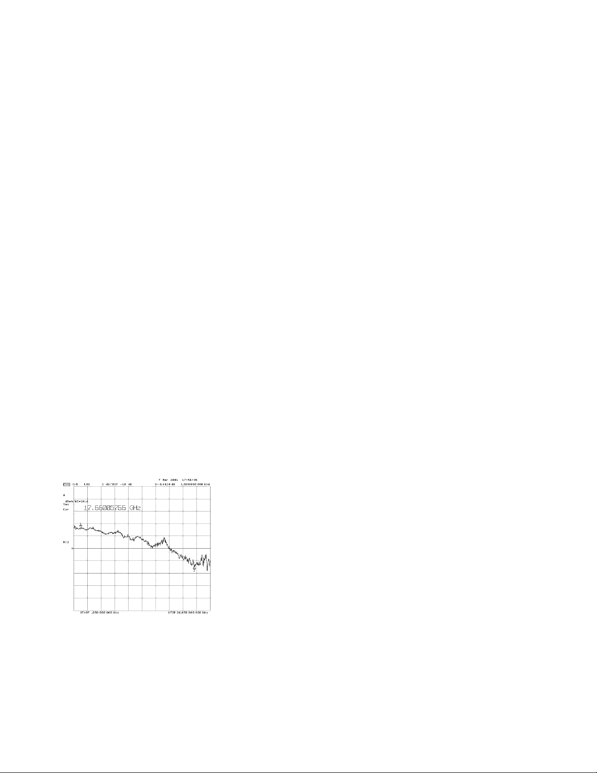
Figure 1. O/E Port 1 Characteristic Relative Frequency
Response Error.
Limit lines are the system relative frequency response accuracy
specifications from Table 1. Traces are actual measured data taken
from 12 instruments.
Figure 2. O/E Port 1 Characteristic Peak-to-Peak
Repeatability.
The above graph shows the worst case deviation across
a 20 GHz span between any 2 units in a sample set of 12,
as shown in Figure 1.
Optical-to-Electrical Device
Measurement Specifications
Figure 3. O/E Port 2 Characteristic Relative Frequency
Response Error.
Limit lines are the system relative frequency response
accuracy specifications from Table 1. Traces are actual
measured data taken from 12 instruments.
Figure 4. O/E Port 2 Characteristic Peak-to-Peak
Repeatability.
The above graph shows the worst case deviation across
a 20 GHz span between any 2 units in a sample set of 12,
as shown in Figure 1-3.

6
O/E Frequency Response Error
for Different Reflection Coefficients
A significant error term in this measurement is the electrical port match of the device under
test (DUT). The following table lists the measurement uncertainty as a function of DUT electrical reflection coefficient. On PORT 1 measurements, you can perform response and match
calibration to achieve values comparable to measurements of devices with ρ = ≤ 0.25 as shown
in Table 1.
Optical-to-Electrical Relative Frequency Response Versus ρ
Frequency Range ρ < 0.5 Specification ρ < 1.0 Specification
0.05 to 11 GHz ± 1.25 ± 2.35
11 to 20.05 GHz ± 1.70 ± 3.5
System Dynamic Range Characteristics
and Responsivity Measurement Range
The following table shows the maximum and minimum values of the O/E device under test
(DUT) frequency response.
Optical-to-Electrical Measurement Performance Data
Description Frequency Range Characteristic
System Dynamic Range 0.05 to 0.84 GHz 77 dB
0.84 to 20.05 GHz 100 dB
Responsivity Measurement Range
1
0.05 to 0.84 GHz Maximum Value
+43 dB A/W
Minimum Value
-34 dB A/W
0.84 to 20.05 GHz Maximum Value
+43 dB A/W
Minimum Value
-57 dB A/W
1
Pertains to a 10 Hz IF bandwidth.

7
Relative frequency response can be used to calculate the error in measuring
the 3 dB bandwidth of an E/O device.
Relative Frequency Response Performance Data
Table 2
Electrical-to-Optical Measurement Performance Data
Description Frequency Range Specification
1
System Relative Frequency Response Accuracy 0.05 to 0.5 GHz ±1.15 dB
0.5 to 11 GHz ±0.85 dB
11 to 20.05 ±0.90 dB
1
Applies to a device with ρ = ≤ 0.25 and measurement settings of IF bandwidth = 30 Hz and smoothing = 0.5%.
Electrical-to-Optical Device
Measurement Specifications
Figure 5. E/O Characteristic Relative Frequency
Response Error
Limit lines are the system relative frequency response
accuracy specifications from Table 2. Traces are actual
measured data taken from 12 instruments.
Figure 6. E/O Characteristic Peak-to-Peak Repeatability
The above graph shows the worst case deviation across
a 20 GHz span between any 2 units in a sample set of 12,
as shown in Figure 5.

8
E/O Frequency Response Error for Different Reflection Coefficients
A significant error term in this measurement is the electrical port match of the device under test (DUT). The following
table lists the measurement uncertainty as a function of DUT electrical reflection coefficient. If you perform a response
and match calibration, you can achieve values comparable to measurements of devices with ρ = ≤ 0.25 as shown in
Table 2.
Electrical-to-Optical Relative Frequency Response Versus ρ
Frequency Range ρ < 0.5 Specification ρ < 1.0 Specification
0.05 to 0.5 GHz ± 1.75 ± 3.10
0.5 to 11 GHz ± 2.05 ± 3.35
11 to 20.05 GHz ± 2.40 ± 3.40
Electrical-to-Optical Measurement Dynamic Range Characteristics
Electrical-to-Optical Measurement Dynamic Range
1
Description Frequency Range Characteristic
System Dynamic Range 0.05 to 20.05 GHz 80 dB
Electrical-to-Optical Measurement Responsivity Measurement Range
The following table shows the maximum and minimum values of the E/O device under test (DUT) frequency
response, measured with microwave power applied from microwave port 1. The dynamic range stays constant
irrespective of the microwave port power. That is, the maximum and the minimum dB W/A that can be
measured increase with reduced microwave port power.
Electrical-to-Optical Measurement Responsivity Measurement Range
1
Maximum Value Minimum Value
Power at Port 1 (dB W/A) (dB W/A) Dynamic Range
(dBm) Characteristic Characteristic (dB) Characteristic
5 -30 -110 80
-65 40 -40 80
1
Pertains to a 10 Hz IF bandwidth.

9
8703B General Information
Group delay measurements
Group delay is computed by measuring the phase change within a specified frequency aperture (determined by the frequency span and the
number of points per sweep). The phase change, in degrees, is then
divided by the frequency aperture, in Hz (times –360).
Aperture
Determined by the frequency span, the number of steps per sweep, and
the amount of smoothing applied. (Minimum aperture limited by source
frequency resolution of 1 Hz.)
Minimum aperture = (frequency span) / (number of points–1)
Maximum aperture = 20 % of the frequency span
Range
The maximum delay is limited to measuring no more than ±180 degrees of
phase change within the minimum aperture. For example, with a
minimum aperture of 1 Hz, the maximum delay that can be measured is
500 milliseconds.
Accuracy
Accuracy is a function of the uncertainty in determining the phase
change. The following is a general formula for calculating typical accuracy, in seconds, for a specific group delay measurement.
±0.003 x Phase Uncertainty (deg)
Aperture (Hz)
Data accuracy enhancement
Lightwave measurement calibration types
Response: Simultaneously accounts for magnitude and phase errors due
to a system’s modulation frequency response. This applies for either
transmission or reflection tests.
Response and match: Accounts for magnitude and phase responses as
well as microwave source and receiver mismatch errors. The isolation
part of this calibration can be included to compensate for directivity
(reflection) and crosstalk (transmission).
Response and isolation: Compensates for modulation frequency
responses plus directivity (reflection) or crosstalk (transmission).
System Bandwidths
IF bandwidth settings
■
6000 Hz
■
3700 Hz
■
3000 Hz
■
1000 Hz
■
300 Hz
■
100 Hz
■
30 Hz
■
10 Hz

Description Specification Characteristic
Rear Panel
Electrical test port bias input
Maximum voltage ±40 Vdc
Maximum current ±500 mA
VGA Video Output 15-pin mini D-Sub; female. Drives VGA compatible monitors.
GPIB Type-57, 24-pin; Microribbon female
Parallel Port 25-pin D-Sub (DB-25); female;
may be used as printer port or general purpose I.O. port
RS232 9-pin D-Sub (DB-9); male
Mini-DIN Keyboard/Barcode Reader 6-pin mini DIN (PS/2); female
Line Power A third-wire ground is required.
Frequency for Microwave Test Set 47 Hz to 63 Hz
Frequency for Lightwave Test Set 50 Hz to 60 Hz
Voltage at 115 V setting 90 V to 132 V 115 V
Voltage at 230 V setting 198 V to 265 V 230 V
VA Maximum for Microwave Test Set 450 VA max
VA Maximum for Lightwave Test Set 70W max
Front Panel
RF Connector 3.5-mm precision (male)
Operating Environment
Temperature +20°C to +30°C Instrument powers up, phase locks, and displays no error messages
within this temperature range.
Humidity 5% to 95% at +30°C
(non-condensing)
Altitude 0 to 4.5 km (15,000 ft)
Storage Conditions
Temperature -40°C to +55°C
Humidity 5% to 95% RH at +40°C
(non-condensing)
Altitude 0 to 15.24 km (50,000 ft)
Cabinet Dimensions
Height x Width x Depth (323 x 430x 476 mm)
(12.71 x 16.93 x 18.74 inches)
Cabinet dimensions exclude front and rear protrusions.
Weight
Shipping 151 lb
Net 76 lb
Internal Memory - Data Retention Time
with 3 V, 1.2 Ah Battery
1
70°C 250 days (0.68 year)
40°C 1244 days (3.4 years)
25°C 10 years
1
Analyzer power is switched off.
10
8703B General Information
(continued)

11
Performance Definitions
Specifications: Warranted performance. Specifications include
guardbands to account for the expected statistical performance
distribution, measurement uncertainties, and changes in
performance due to environmental conditions.
Characteristics: Useful, non warranted, information about the
functions and performance of the system.
Calibration Cycle
Agilent Technologies warrants instrument specifications over the
recommended calibration interval. To maintain specifications,
periodic recalibrations are necessary. We recommend that the
analyzer be calibrated at an Agilent Technologies service facility
every 12 months.
User Calibration Cycle
A user calibration, also known as a measurement calibration, should
be performed at least once every 8 hours. If the ambient temperature
drifts, then you should perform a calibration more frequently.

Agilent Technologies’
Test and Measurement Support, Services, and Assistance
Agilent Technologies aims to maximize the value you receive, while minimizing your risk and
problems. We strive to ensure that you get the test and measurement capabilities you paid for and
obtain the support you need. Our extensive support resources and services can help you choose
the right Agilent products for your applications and apply them successfully. Every instrument
and system we sell has a global warranty. Support is available for at least five years beyond the
production life of the product. Two concepts underlie Agilent’s overall support policy: “Our
Promise” and “Your Advantage.”
Our Promise
Our Promise means your Agilent test and measurement equipment will meet its advertised
performance and functionality. When you are choosing new equipment, we will help you with
product information, including realistic performance specifications and practical recommendations
from experienced test engineers. When you use Agilent equipment, we can verify that it works
properly, help with product operation, and provide basic measurement assistance for the use of
specified capabilities, at no extra cost upon request. Many self-help tools are available.
Your Advantage
Your Advantage means that Agilent offers a wide range of additional expert test and measurement
services, which you can purchase according to your unique technical and business needs. Solve
problems efficiently and gain a competitive edge by contracting with us for calibration, extra-cost
upgrades, out-of-warranty repairs, and on-site education and training, as well as design, system
integration, project management, and other professional engineering services. Experienced Agilent
engineers and technicians worldwide can help you maximize your productivity, optimize the return
on investment of your Agilent instruments and systems, and obtain dependable measurement
accuracy for the life of those products.
By internet, phone, or fax, get assistance with all your test & measurement needs.
Online assistance:
www.agilent.com/comms/lightwave
Phone or Fax
United States:
(tel) 1 800 452 4844
Canada:
(tel) 1 877 894 4414
(fax) (905) 282 6495
China:
(tel) 800-810-0189
(fax) 1-0800-650-0121
Europe:
(tel) (31 20) 547 2323
(fax) (31 20) 547 2390
Japan:
(tel) (81) 426 56 7832
(fax) (81) 426 56 7840
Korea:
(tel) (82-2) 2004-5004
(fax)(82-2) 2004-5115
Latin America:
(tel) (305) 269 7500
(fax) (305) 269 7599
Taiwan:
(tel) 080-004-7866
(fax) (886-2) 2545-6723
Other Asia Pacific Countries:
(tel) (65) 375-8100
(fax) (65) 836-0252
Email: tm_asia@agilent.com
Product specifications and descriptions in this document subject to change without notice.
© 2001, 2002 Agilent Technologies
Printed in USA April 29, 2002
5988-3599EN
www.agilent.com/find/emailupdates
Get the latest information on the
products and applications you select.
 Loading...