

Page 1

Agilent
8644B, 8664A, 8665B
High Performance RF Signal Generators
Data Sheet
A commitment to value in signal generators
Page 2

2
Agilent’s high performance RF signal generators – choose one for…
…Best spectral purity
• 252 kHz to 1030 MHz, 2060 MHz (Option 8644B-002)
• Lowest SSB phase noise and spurious
• Highest output power
• Lowest residual FM
• AM, FM, pulse modulation
• Built-in 2 GHz counter (Option 8644B-011)
• VOR/ILS signal simulation (Option 8644B-009)
• Ultra low leakage (Option 8644B-010)
…High RF frequency coverage
• 100 kHz to 3000 MHz – 8664A, 4200 MHz – 8665B – 6000 MHz
• Low SSB phase noise (Option 8664A-004 or Option 8665B-004)
• AM and wideband FM
• High performance pulse modulation (Option 8664A-008 or Option 8665B-008)
• Ultra low leakage (Option 8664A-010 or Option 8665B-010)
8644B
8664A and 8665B
Page 3

3
Choose one for your application...
8644B 8664A 8665B
1 or 2 GHz 3 GHz 6 GHz
RF communications
Out-of-channel Ideal for receivers Ideal for receivers Same performance as
receiver testing
1
with ≥ 90 dB selectivity with ≥ 90 dB selectivity 8664A but up to 6 GHz
and/or spurious with Option 8664A-004,
immunity of ≥ 85 dB and spurious immunity of
< 85 dB to 3 GHz
General purpose Lowest possible phase Wideband FM with Lowest noise and
noise and spurious rates to 6 MHz for spurious to 6 GHz
for R&D simulation of many
new digital systems
Component test Highest output power Ideal clock source with Best output level
for mixer testing low phase jitter for high accuracy to 6 GHz
speed digital components for response testing
Radar/EW testing Full functionality for Optional pulse Same performance as
R&D and manufacturing modulation with internal 8664A but up to 6 GHz
delay and width adjust for coverage of most
surveillance radars
Avionics Option 8644B-009 Coverage of most Same performance as
provides specified weather and avionics 8664A up to 6 GHz
VOR/ILS signal radars. Option 8664A-008
simulation provides pulse modulation
capable of generating
appropriate pulse width
and delay internally
1. For FM receivers with approximately 14 kHz IF BW and 25 kHz channel spacing
Page 4

4
Performance backed by Agilent’s reputation and manufacturing experience
Every Agilent Technologies’
signal generator meets specifications that would reject
most other signal generators
Before any Agilent Technologies’ signal
generator is introduced, specifications are
set to assure that the product will perform
consistently for your application. The
specification setting process is reflective
of the quality that Agilent has always
strived to deliver. An explanation of Agilent’s
specification setting process will show the
confidence that you can have when
selecting an Agilent Technologies
signal generator.
The model used for specification setting is
illustrated in the above right figure. The
following text defines each element in
the figure.
• Production margin is the difference
between the average product performance and the test line limit (TLL). This
TLL is the pass/fail limit used by the
production line at final test under
standard environmental conditions.
• Delta environmental represents the
possible change in performance over
the environmental extremes (e.g.,
temperature and humidity).
• Drift represents the change in performance over the calibration period.
• Measurement uncertainty accounts for
possible measurement errors in the
equipment used to characterize the
signal generator.
• Customer guardband represents any
additional margin necessary to ensure a
worst case scenario.
This process means that whether the signal
generator is placed in a high temperature
environment such as at the top of a rack of
equipment or a well controlled environment,
the performance stated in our specifications
can be relied on for your most exacting
applications. This process guarantees that
the signal generator is introducing the
minimum error possible in the measurements you are performing.
Typical performance
Since some applications push the limits
of specifications, Agilent Technologies
also provides data that indicates typical
performance. This typical performance is
generally set at the test line limit (TLL),
which is significantly better than the warranted specification. Use the typical data
when comparing different products, or when
your application pushes the limit on a given
specification. The following information
highlights typical performance for the
most common areas of interest for the
8644B, 8664A and 8665B.
Production
margin
Delta
environmental
and drift
Measuremant
uncertainty
Customer
guardband
Average TLL SPEC
(warranted)
Page 5
5
Typical performance, for
applications that push
specifications
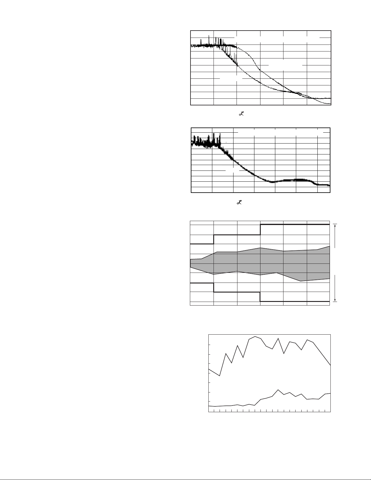
SSB phase noise
SSB phase noise is an important specification of a signal generator if it is to be used
for measuring the adjacent channel selectivity of a receiver. If the phase noise of the
signal generator is too high at frequency
offsets equal to the channel spacing, the
test results might indicate a failure of the
receiver when it is actually functioning
properly. If the selectivity is ≥ 90 dB, the
8644B (or Option 8664A-004, or Option
8665B-004) is recommended.
Output level accuracy
Output level accuracy is a combination of
temperature variation, flatness over frequency, and the signal generator’s internal
attenuator and detector accuracies. The
graph represents worst case output level
accuracy of a sampling of 8665Bs. All of
these units fall within the shaded area.
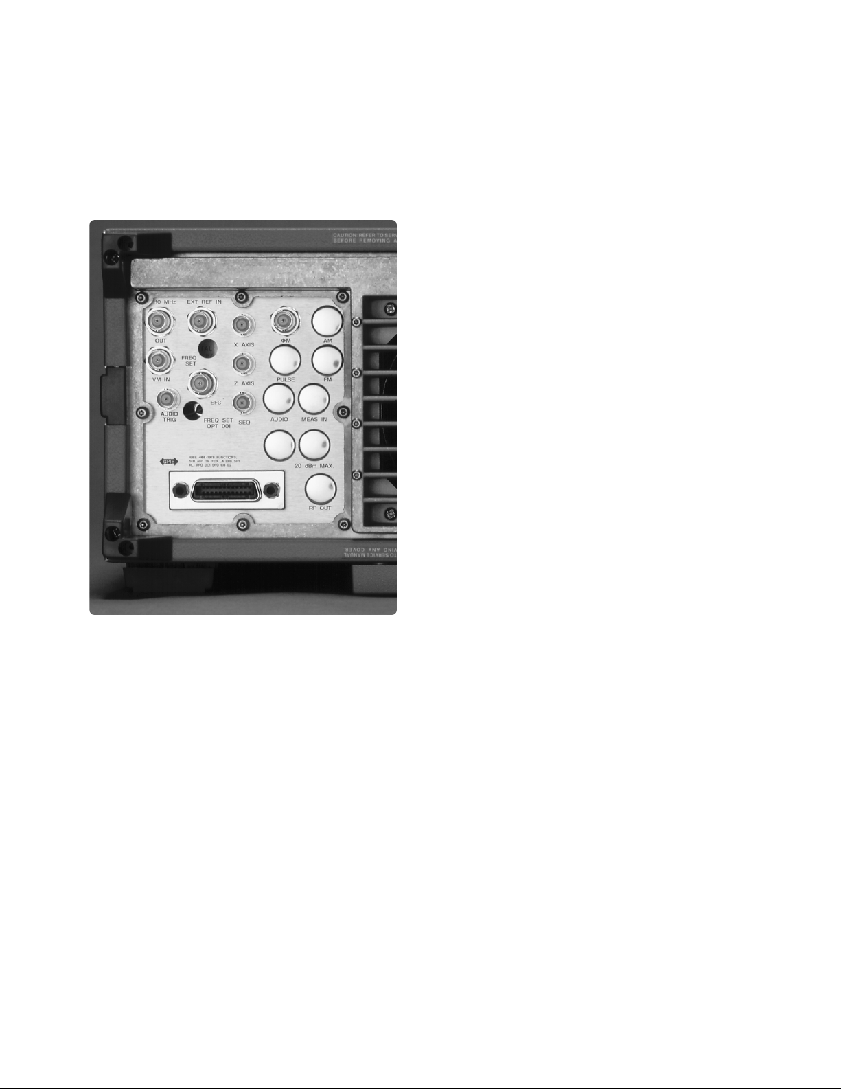
RF leakage
Due to radios becoming more sensitive
and operating at higher frequencies, the
traditional two-turn loop measurement of
RF leakage has become inadequate. To
overcome the shortcomings of the twoturn loop, Agilent has developed a new
measurement technique using resonant
dipole antennas, which is 20 to 25 dB more
sensitive than the two-turn loop method.
Agilent has been able to reduce the level
of radiated emissions in its newer signal
generators through innovative design and
packaging. Understanding that not all
applications require the lowest possible
emissions, Option 010 (i.e., 86xxx-010) is
available on all of these performance
signal generators.
-60
-80
Typical SSB phase noise and spurs at 1 GHZ
-100
-120
Option 004
-140
SSB phase noise (dBc/Hz)
-160
10 100 1K 10K 100K 1M 10M
-60
-80
-100
-120
-140
SSB phase noise (dBc/Hz)
-160
10 100 1K 10K 100K 1M 10M 40M
Typical output level accuracy for the 8665B at - 115 dBm
2.0
1.0
0.5
(f) [dBc/Hz] vs. f[Hz]
Typical SSB phase noise and spurs at 1 GHZ
8644B
(f) [dBc/Hz] vs. f[Hz]
8664A 8665B
standard
-0.5
-1.0
-2.0
1000 2000 3000 4000 5000 6000
-85
-90
-95
-100
dBm
-105
-110
-115
-120
-125
515 550 600 650 700 750 800 850 900 950 1029
Carrier frequency (MHz)
8644B typical leakage
Standard
Option 8644B-010
MHz
Specification
Page 6

6
Internal modulation source
• Low distortion sinewaves to 400 kHz
with variable phase and amplitude.
• Triangle, sawtooth and squarewaves to
50 kHz with variable phase and amplitude.
• White Gaussian noise with variable
amplitude.
• Two independent sources for two-tone
testing.
Optional pulse modulation
(Options 8664A-008 and
8665B-008)
• An Agilent designed GaAs pulse
modulator provides the exceptional
performance that is so critical for pulsed
applications.
• < 5 ns rise/fall times, > 80 dB on/off
ratio
• Built-in pulse generator features
include variable pulse delay and width
from 50 ns to 999 ms. This saves
purchasing additional equipment.
• Leveled RF output maintains accuracy
while in pulse modulation.
High reliability electronic
attenuator (optional on 8644B)
For applications up to 1 GHz, the electronic
attenuator provides increased reliability.
Instead of using mechanical relays, the
electronic attenuator uses solid-state components for setting output levels accurate
to within ±1.0 dB. The Agilent patented
design uses PIN switching elements with
three million hours of MTBF, giving the
attenuator an estimated 0.2% failure rate.
Features that improve the usability of Agilent’s 8644B, 8664A and 8665B
for your application!
Page 7
7
Wideband FM (8664A and
8665B)
• Typical rates to 5 MHz with 2 MHz of
deviation, or rates to 800 kHz with
10 MHz of deviation (fc> 1500 MHz)
allows testing of most wideband
receivers.
• Excellent FM linearity is inherent due to
YIG oscillator design.
• Stable dc-coupled FM for measurements
that require low carrier drift.
Performance signal generator
series features
• High stability oven controlled timebase
is standard.
• Surface mount construction for
improved reliability.
• Three year calibration cycle (MTBC)
means less time in the calibration lab.
• Built-in self-diagnostics and calibration
saves valuable time by significantly
reducing down time.
2 GHz frequency counter
(Option 8644B-011)
• 20 Hz to 2 GHz frequency counting via
front panel connector.
• Cost and space efficient solution for
applications involving audio frequency
measurements, local oscillator, IF and
transmitter testing.
• Eliminates the need to externally couple
the timebase references when using an
external counter.
Page 8

8
8644B 8664A, 8665B
Frequency
Range: 0.252 to 1030 MHz 0.1 to 3000 MHz 8664A
0.252 to 2060 MHz, Option 8644B-002 0.1 to 6000 MHz 8665B
Resolution: 0.01 Hz 0.01 Hz
Accuracy (std. timebase): 0.375 x 10
-6
times carrier in Hz 0.375 x 10⁻⁶times carrier in Hz
< 1 year of calibration
Switching speed (typical): < 350 ms < 50 ms (within 0.33 ppm)
(within 100 Hz) < 100 ms 8664A-004 or 8665B-004
Spectral purity
SSB phase noise (dBc/Hz):
(at 20 kHz offset)
Carrier (MHz) Standard Option 004 (866xx-004)
4120 to 6000 NA –105 –116
3000 to 4120 NA –105 –122
2060 to 3000 NA –111 –122
1030 to 2060 –130 (Option 8644B-002) –111 –128
515 to 1030 –136 (–142 typical) –117 –134
257.5 to 515 –142 –122 –139
128.5 to 257.5 –145 N/A N/A
0.25 to 128.5 –145 N/A N/A
8664A, 8665B
187.5 to 257.5 NA –128 –144
0.1 to 187.5 NA –117 –131
Nonharmonics: < –105 dBc, > 10 kHz offset, < –100 dBc, > 10 kHz offset,
0.252 to 1030 MHz 187.5 to 2060 MHz
< –100 dBc, > 10 kHz offset, < –90 dBc, > 10 kHz offset,
1030 to 2060 MHz 2060 to 6000
1
MHz, 0.1 to 187.5 MHz
Harmonics: < –25 dBc, output ≤ +10 dBm < –30 dBc, output ≤ +10 dBm
Subharmonics: None, 0.252 to 515 MHz < –75 dBc, 0.1 to 1500 MHz
< –52 dBc, 515 to 1030 MHz < –40 dBc, 1500 to 3000 MHz
< –40 dBc, 1030 to 2060 MHz < –50 dBc, 3000 to 60001 MHz
Residual FM (Hz rms): Standard Standard/Option 004 (866xx-004)
Carrier (MHz) 3 kHz BW 15 kHz BW 3 kHz BW 15 kHz BW
2060 to 60001 –– < 60/< 10 < 80/< 32
1030 to 2060 < 2 < 4 < 15/< 2.5 < 20/< 8
515 to 1030 < 1 < 2 < 7.5/< 1.2 < 10/< 4
257.5 to 515 < 0.5 < 1 < 7.5/< 1.2 < 10/< 4
0.25 to 257.5 < 0.5 < 0.5 ––
8664A, 8665B
187.5 to 257.5 –– < 7.5/< 1.2 < 10/< 4
0.1 to 187.5 –– < 15/< 2.5 < 20/< 8
Residual AM: < 0.01% AM rms < 0.04% AM rms
(0.3 to 3 kHz post det. BW)
SSB AM noise floor (dBc/Hz): < –157, 10 dBm, < 1030 MHz < –137, 13 dBm, < 187.5 MHz
(offsets > 100 kHz) < –150, 10 dBm, < 2060 MHz < –150, 13 dBm, > 187.5 MHz
Internal reference oscillator Standard high stability Option 001 high stability with EFC
Aging: +1.5 x 10
-8
/day after ten days ±3 x 10
-10
/day after 10 days
Temperature: +7 x 10
-10
, 0 to 55 °C ±6 x 10
-10
, to 55 °C
Line voltage: ±2 x 10
-10
, (+5%, -10%) ±1 x 10
-10
, ±10%
Output: 10 MHz, > 0.15 V
rms
level into 50 Ω 10 MHz, > 1 V
rms
level into 50 Ω
External reference input: Accepts 10 MHz ±5 ppm and a level range of 0.5 V to 2 V
rms
into 50 Ω
Electronic frequency control (EFC): Option 001 (86xxx-001) only, +0.01 ppm for ±1 Vdc at rear panel connector, voltage range ±10 Vdc,
input impedance 10k Ω
Specifications
1. 3000 MHz for 8664A, 6000 MHz for 8665B
Page 9

9
8644B 8664A, 8665B
Output level
Range: +16 to –137 dBm, +13 to -139.9 dBm
+13 dBm, 8644B-002/005 +9 dBm, Option 8664A-008 or 8665B-008
Resolution: 0.01 Hz 0.01 Hz
Absolute accuracy: ±1 dB, output ≥ –127 dBm ±1 dB, output ≥ –119.9 dBm, 1 - 1000 MHz
±3 dB, output < –127 dBm ±1.5 dB, output ≥ –119.9 dBm, 1000 to 3000 MHz
±2 dB, output ≥ –119.9 dBm, 3000 to 6000
1
, < 1 MHz
±3 dB, output ≥ –129.9 dBm
Reverse power protection: 50 watts 25 watts
2
, 0.1 to 2060 MHz
1 watt, > 2060 MHz
Third order intermod: < –50 dBc < –47 dBc
(frequencies < 1300 MHz, two
signals at +8 dBm, 25 kHz apart
through a resistive combiner)
Overrange: Typically 2 dB Typically 2 dB
Switching speed (typical): < 50 ms < 50 ms
SWR:
Output level < 3000 MHz ≥ 3000 MHz
≥ 0 dBm < 2.2:1 < 1.75:1 < 2.0:1
< 0 dBm < 1.5:1 < 1.5:1 < 1.75:1
Output impedance: 50 Ω 50 Ω
Amplitude modulation
Depth: 0 to 100%, output ≤ +7 dBm 0 to 100%, output ≤ +7 dBm
Resolution: 0.1% 0.1%
Bandwidth (3 dB): dc to > 100 kHz, > 128 MHz dc to > 10 kHz for > 10 MHz
Accuracy: 1 kHz rate ±(7% of setting +1%) up to 80% depth ± (6% of setting +1%) up to 90% depth
Distortion: < 3%; < 4%, 8644B-002 < 4%
30% depth, 1 kHz rate
Incidental phase modulation: < 0.2 radians peak < 0.2 radians peak, ≤ 2000 MHz
(at 30% depth, 1 kHz rate) < 0.2 radians peak, > 2000 MHz
External input impedance: 600 Ω 600 Ω
Frequency modulation
Maximum peak deviation: 20 MHz/200 kHz3, > 1030 MHz 20 MHz, 3000 to 60001MHz
10 MHz/100 kHz3, > 515 MHz 10 MHz, 1500 to 3000 MHz
5 MHz/50 kHz3, > 257.5 MHz 5 MHz, 750 to 1500 MHz
2.5 MHz/25 kHz, > 128.5 MHz 2.5 MHz, 375 to 750 MHz
1.25 MHz/12.5 kHz
3
, > 64 MHz 1.25 MHz, 187.5 to 375 MHz
62.5 kHz/6.25 kHz3, > 32 MHz 5 MHz, < 187.5 MHz
Deviation halves per lower octave
(> 16, > 8, > 4, > 2, > 1, > 0.5 MHz)
Resolution: 2.5% of setting 2.5% of setting
Bandwidth (3 dB): dc to 100 kHz dc to 800 kHz
Carrier accuracy in FM: ±0.5% of setting ±0.6% of setting
Indicator accuracy: < 5%, < 30 kHz rates ±9%, < 20 kHz rates
< 10%, < 100 kHz rates ±11%, < 20 kHz rates, 8664A-004 or 8665B-004
Distortion: < 5%, < 1%
3
20 Hz to 100 kHz < 1%, 20 Hz to 20 kHz rates
Incidental AM: < 0.5%, deviation ≤ 20 kHz < 0.3%, deviation ≤ 20 kHz
External group delay: < 10 µs, ≤ 100 kHz rates < 30 µs, ≤ 2 0 kHz rates
External input impedance: 600 Ω 600 Ω
Specifications (continued)
1. 3000 MHz for 8664A, 6000 MHz for 8665B
2. One watt on 8665B
3. Low noise mode three
Page 10

10
8644B 8664A, 8665B
Pulse modulation
Options 8664A-008 and 8665B-008
On/off ratio: > 35 dB, > 80 dB, > 1030 MHz > 80 dB
Rise/fall time, 10 to 90%: < 100 ns < 5 ns
Repetition rate: dc to 1 MHz dc to 10 MHz
Internal width/delay: N/A Variable from 50 ns to 1 s ±5%
accuracy, 0.2% of full scale
resolution
Minimum width: 0.5 ms 10 ns
Video feedthrough/overshoot: < 15% < 25%
Output level accuracy: ±2 dB Same as standard
External inputs/outputs: Input level: on state; > 3.0 V
peak
Input level: TTL into 50 Ω or
(600 Ω input impedance) off state; < 0.8 V
peak
Schottky TTL
Sync out and video out: TTL
into 50 Ω
Internal modulation source
Number of sources: Two sources simultaneously available through summation, independently adjustable in frequency,
phase, amplitude and waveform. Source one may also be internally modulated with AM, FM, phase
modulation and pulse modulation to create a subcarrier waveform.
Waveforms and rates: Sine, white Gaussian noise; 0.1 Hz to 400 kHz
Triangle, sawtooth, square; 0.1 Hz to 50 kHz
Frequency accuracy: Same as timebase
Output level (into 600 Ω): 1 V
peak
, 2 V
peak
for 8644B
Output resolution: 2 mV
peak
Total harmonic distortion: < 0.1%, ≤ 20 kHz rates
Frequency sweep
Digital sweep: Digitally stepped sweep over entire frequency range. Linear/log selection. 0.5 to 1000 sec sweeps.
Markers/Z axis output: Three markers available /Z axis output nominally +5 V/X axis output nominally 0 to 10 V.
Phase continuous sweep: 40 MHz of span available at maximum carrier frequency. Twenty ms to ten sec sweep times.
Remote programming
Interface: GPIB (IEEE 488.2-1987).
Control language: Hewlett-Packard Systems Language (HP-SL). All functions controlled except power.
IEEE-488 functions: SH1, AH1, T6, TEO, L4, LEO, SR1, RL1, PPO, DC1, DTO, CO, E2.
Specifications (continued)
Page 11
11
8644B 8664A, 8665B
Avionics Option 8644B-0009 8644B-009 provides the performance needed for testing VOR N/A
and ILS (localizer, glide slope and marker beacon) receivers.
8644B-009 provides guaranteed specifications necessary to
make these demanding tests.
VOR (108 to 118 MHz) Bearing accuracy: 0.1°, frequency accuracy: Same as timebase,
AM accuracy (30%): ±5% of setting, AM distortion: 2%,
FM accuracy (480 Hz dev.): ±1.5 Hz
ILS: localizer/glide slope DDM resolution: Localizer: 0.0002 Glide slope: 0.0004
(108 to 112 MHz/329.3 to DDM accuracy: Localizer: ±0.0004 ±5% of DDM
335 MHz) Glide slope: ±0.0008 ±5% of DDM
Marker beacon (75 MHz): AM accuracy: ±5% of setting AM distortion: 2%
AM accuracy (95%): ±5% of setting +1% AM distortion: 5%
2 GHz counter Option 011
Frequency range: 20 Hz to 2 GHz in three ranges N/A
Sensitivity: 25 mV
rms
(–19 dBm into 50 Ω)
Maximum input: 2.25 V
rms
(+20 dBm into 50 Ω)
Impedance: 50 Ω, 10 MHz to 2 GHz; 1 M Ω shunted by < 65 pf, < 10 MHz
Coupling: ac
Gate times: 0.1s to 1s in 0.1s steps
Measurement resolution: Measured frequency (Hz) x 10
-8
/gate time or 0.01 Hz if greater
Measurement uncertainty: (± time base accuracy) plus (± measurement resolution)
General
Power requirements: ±10% of 100 V, 120 V, 220 V or 240 V; 48 to 440 Hz; 500 VA except 8644B 400 VA.
Operating temperature: 0 to 55 °C
Leakage: Conducted and radiated interference meets MIL STD 461 B REO2 and FTZ 1046.
Leakage is measured into a resonant dipole antenna, one inch from the instrument’s surface
with output level < 0 dBm (all inputs/outputs properly terminated, f
c
< 1 GHz).
Leakage is typically < 16 µV or < 2 µV with Option 010, measured at the front panel.
The older two-turn loop method of measurement is typically < 1 µV or < 0. 1 µV for Option 010.
Acoustic noise: Typically < 5.5 bels
Storage registers: Ten full function and 40 frequency/amplitude registers.
Calibration/diagnostics: Internal calibration and diagnostics functions are available to the user. Built-in test capability
locates circuit malfunctions to allow repair through module replacement.
Calibration interval: Recommended three years (MTBC).
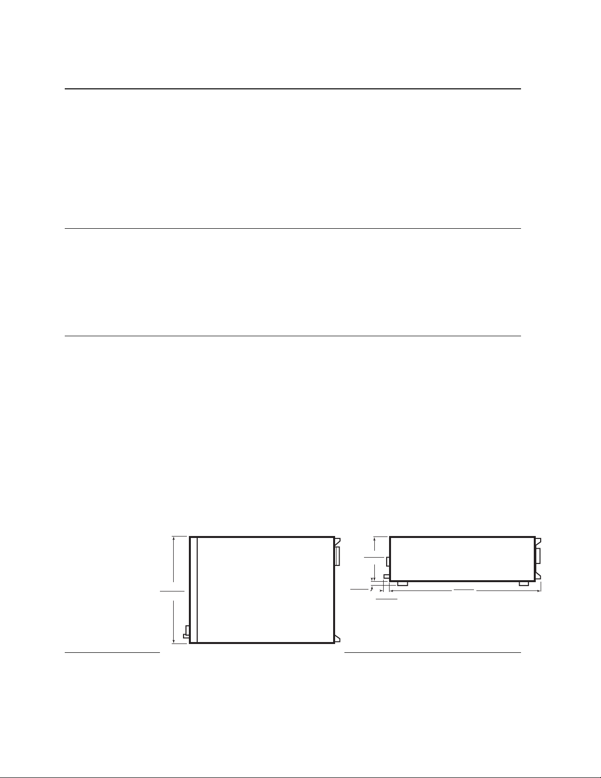
Weight: 8644B; 30 kg (67 lbs). 8664A/8665B; 35 kg (78 lbs)
Dimensions: 177H x 426W x 601D mm (7 x 16.8 x 23.7 in.). Option 010 adds 35 mm (1.4 in.) to depth.
Specifications (continued)
177 mm
(7.0 in.)
426 mm
16.8 in.)
TOP
17 mm
(0.7 in.)
23 mm
(0.09 in.)
SIDE
Option 010 in creases depth by 35 mm (1.4 in.)
601 mm
23.7 in.)
Page 12

12
Ordering information
Note: To add options to a product, specifiy the model number, followed by the
option number. For example:
Models: 8644B, 8664A, 8665B
Option 8644A-005 or Option 8665B-010
8644B 8664A
8665B
Options:
001 High stability time base with EFC ✓✓
002 2 GHz doubled output ✓✓
003 Rear panel input/output ✓✓
004 Low noise option Not applicable ✓
005 Electronic attenuator (N/A with Option 002) ✓✓
008 Pulse modulation ✓✓
009 Specified VOR/ILS ✓✓
010 Reduced leakage configuration ✓✓
011 2 GHz internal frequency counter ✓✓
907 Front handle kit (5061-9690) ✓✓
908 Rack flange kit (5061-9678) ✓✓
909 Combined front/rack flange kit (5061-9684) ✓✓
915 Add service manual service kit 08645-61116 08665-61116
R1281A Additional 3 years of return warranty ✓✓
Agilent Technologies’ Test and Measurement Support,
Services, and Assistance
Agilent Technologies aims to maximize the value you
receive, while minimizing your risk and problems. We
strive to ensure that you get the test and measurement
capabilities you paid for and obtain the support you need.
Our extensive support resources and services can help
you choose the right Agilent products for your applications
and apply them successfully. Every instrument and system
we sell has a global warranty. Support is available for at
least five years beyond the production life of the product.
Two concepts underlie Agilent’s overall support policy: “Our
Promise” and “Your Advantage.”
Our Promise
Our Promise means your Agilent test and measurement
equipment will meet its advertised performance and
functionality. When you are choosing new equipment, we
will help you with product information, including realistic
performance specifications and practical recommendations
from experienced test engineers. When you use Agilent
equipment, we can verify that it works properly, help
with product operation, and provide basic measurement
assistance for the use of specified capabilities, at no extra
cost upon request. Many self-help tools are available.
Your Advantage
Your Advantage means that Agilent offers a wide range
of additional expert test and measurement services,
which you can purchase according to your unique technical
and business needs. Solve problems efficiently and gain a
competitive edge by contracting with us for calibration,
extra-cost upgrades, out-of-warranty repairs, and onsite
education and training, as well as design, system integration,
project management, and other professional engineering
services. Experienced Agilent engineers and technicians
worldwide can help you maximize your productivity, optimize
the return on investment of your Agilent instruments and
systems, and obtain dependable measurement accuracy for
the life of those products.
Agilent T&M Software and Connectivity
Agilent’s Test and Measurement software and connectivity
products, solutions and developer network allows you to
take time out of connecting your instruments to your
computer with tools based on PC standards, so you can
focus on your tasks, not on your connections. Visit
www.agilent.com/find/connectivity
for more information.
By internet, phone, or fax, get assistance with all your
test & measurement needs
Online Assistance:
www.agilent.com/find/assist
Product specifications and descriptions in this document
subject to change without notice
© Agilent Technologies, Inc. 2001, 2002
Printed in USA, November 4, 2002
5091-2580E
Phone or Fax
United States:
(tel) 800 452 4844
Canada:
(tel) 877 894 4414
(fax) 905 282 6495
China:
(tel) 800 810 0189
(fax) 800 820 2816
Europe:
(tel) (31 20) 547 2323
(fax) (31 20) 547 2390
Japan:
(tel) (81) 426 56 7832
(fax) (81) 426 56 7840
Korea:
(tel) (82 2) 2004 5004
(fax) (82 2) 2004 5115
Latin America:
(tel) (305) 269 7500
(fax) (305) 269 7599
Taiwan:
(tel) 0800 047 866
(fax) 0800 286 331
Other Asia Pacific Countries:
(tel) (65) 6375 8100
(fax) (65) 6836 0252
Email: tm_asia@agilent.com
www.agilent.com/find/emailupdates
Get the latest information on the products and applications you select.
 Loading...