

Page 1

*TB 9-4931-488-35
DEPARTMENT OF THE ARMY TECHNICAL BULLETIN
CALIBRATION PROCEDURE FOR
SIGNAL GENERATOR, SG1112VlU,
SG1112V2U, AND MIS-28707TY2 (HEWLETT-
PACKARD, MODEL 8640B, OPTIONS 001,
002, 003, 004, AND H66)
Headquarters, Department of the Army, Washington, DC
26 August 2003
Approved for public release; distribution is unlimited.
REPORTING OF ERRORS AND RECOMMENDING IMPROVEMENTS
You can improve this manual. If you find any mistakes or if you know of a way to improve
these procedures, please let us know. Mail your letter or DA Form 2028 (Recommended
Changes to Publications and Blank Forms)directly to: Commander, U.S. Army Aviation and
Missile Command, ATTN: AMSAM-MMC-MA-NP, Redstone Arsenal, AL 35898-5000. A reply
will be furnished to you. You may also provide DA Form 2028 information to AMCOM via email, fax, or the World Wide Web. Our fax number is DSN 788-6546 or Commercial 256-842-
6546. Our e-mail address is: [email protected]. Instructions for sending an electronic
2028 may be found at the back of this manual. For the World Wide Web, use
https://amcom2028.redstone.army.mil.
SECTION I. IDENTIFICATION AND DESCRIPTION
Test instrument identification ........................... 1 2
Forms, records, and reports ................................ 2 3
Calibration description ....................................... 3 3
II. EQUIPMENT REQUIREMENTS
Equipment required ............................................ 4 5
Accessories required ............................................ 5 6
III. CALIBRATION PROCESS
Preliminary instructions ..................................... 6 7
Equipment Setup ................................................ 7 7
Internal reference accuracy ................................. 8 9
Frequency range, accuracy, and stability........... 9 9
________
*This bulletin supersedes TB 9-4931-488-35 dated 11 October 1989.
Paragraph Page
Page 2

TB 9-4931-488-35
Harmonic distortion ............................................. 10 10
Output level and meter accuracy (all models
except those containing option 004).................
Output level and meter accuracy (models
containing option 004)....................................... 12 21
Output level flatness............................................ 13 24
Internal modulation oscillator frequency
accuracy, output voltage and distortion .......... 14 25
AM sensitivity, accuracy, and distortion (all
models except those containing option 004) .... 15 28
AM sensitivity, accuracy, distortion, and
demodulated output (models containing
option 004) ......................................................... 16 31
AM flatness (option 004 only).............................. 17 37
FM sensitivity, accuracy, and distortion ............ 18 39
Power Supply........................................................ 19 43
Final Procedure .................................................... 20 43
Paragraph Page
11 12
SECTION I
IDENTIFICATION AND DESCRIPTION
1. Test Instrument Identification. This bulletin provides instructions for the
calibration of Signal Generator, SG1112V1U (8460BOPT004), SG1112V2U (8640BOPT001),
MIS-28707TY2 (8640BH66) and Hewlett-Packard, Model 8640B, Options 001, 002, 003,
004, and H66. The manufacturers’ manuals were used as the prime data sources in
compiling these instructions. The equipment being calibrated will be referred to as the TI
(test instrument) throughout this bulletin.
a. Model Variations. Option variations are as listed below in (1) through (5).
(1) Option 001 provides a modulation oscillator that is continuously adjustable from
20 Hz to 600 kHz. The oscillator can also be set for 400 Hz or 1 kHz fixed tones.
(2) Option 002 provides an internal, active frequency doubler that extends the
frequency range of the generator to 1024 MHz (to 1100 MHz with over range).
(3) Option 003 protects the generator output circuits from accidental applications of
reverse power up to 50 W.
(4) Option 004 provides a demodulated output and modified AM circuitry for setting
very accurate AM depths. It also has a 1 dB output step attenuator in addition to the
standard 10 dB output step attenuator.
(5) Option H66 which includes option 001 provides an additional control for very fine
adjustment of the output level and improved harmonic content in the RF output signal.
2
Page 3
TB 9-4931-488-35
b. Time and Technique. The time required for this calibration is approximately 8
hours, using the dc and low frequency and microwave technique.
2. Forms, Records, and Reports
a. Forms, records, and reports required for calibration personnel at all levels are
prescribed by TB 750-25.
b. Adjustments to be reported are designated (R) at the end of the sentence in which
they appear. When adjustments are in tables, the (R) follows the designated adjustment.
Report only those adjustments made and designated with (R).
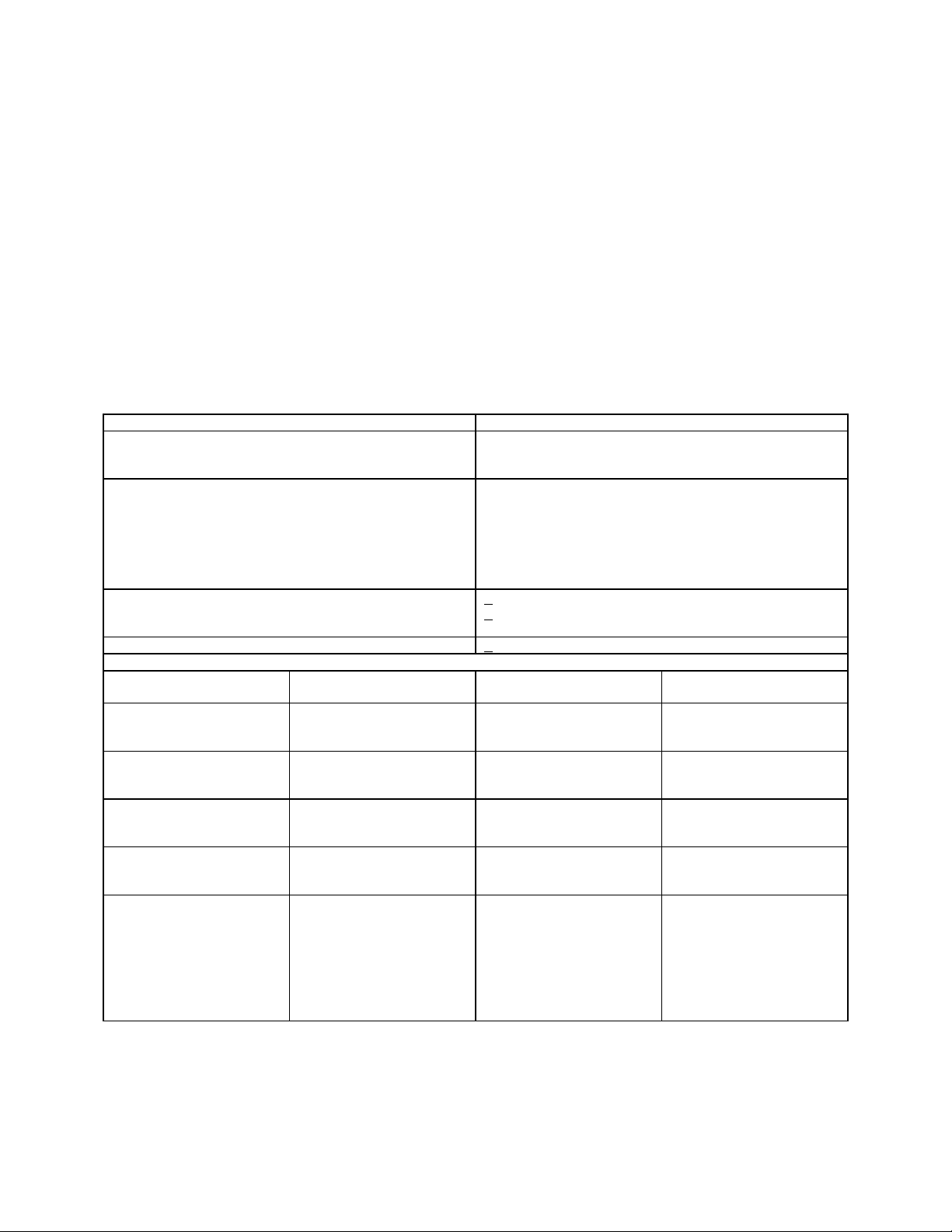
3. Calibration Description. TI parameters and performance specifications which
pertain to this calibration are listed in table 1.
Table 1. Calibration Description
Test instrument parameters Performance specifications
1
Internal reference Range: 5 MHz
Accuracy: +1 ppm
Drift: <0.05 ppm per hr
Frequency Range: 0.5 to 512 MHz
0.5 to 1024 MHz (option 002)
Accuracy: Counter resolution (±1 count) +
reference error ± 2 ppm (locked mode)
Stability: <10 ppm/10 minute (unlocked mode)
<0.1 ppm for +5% to -10% line voltage
change (locked mode
Harmonics (at 1 V ,+ 10 dB output range and below) >30 dB below fundamental, 0.5 to 512 MHz )
>
12 dB below fundamental, 512 to 1024 MHz
(option 002)
Subharmonics (option 002) >20 dB below fundamental, 512 to 1024 MHz
Output Level (Top 10 dB Of Vernier Range)
Options Frequency Range
Output Level (dBm) Accuracy (dB)
(MHz)
Basic, 001, and H66 0.5 to 512 +19 to -7
-7 to -47
-47 to -137
3
002 0.5 to 64 +18.5 to -7
-7 to -47
-47 to -137
3
64 to 512 +18.5 to -7
-7 to -47
-47 to -137
3
512 to 1024 +13 to -7
-7 to -47
-47 to -127
3
003 0.5 to 512 +18.5 to -7
-7 to -47
-47 to -137
3
±1.5
±2.0
±2.5
±1.5
±2.0
±2.5
±2.0
±2.5
±3.0
±3.0
±3.5
±4.0
+1.75
-2.25
+2.25
-2.75
+2.75
-3.25
See footnotes at end of table
3
Page 4

TB 9-4931-488-35
Table 1. Calibration Description - Continued
Test
instrument
parameters
Performance specifications
Output Level (Top 10 dB Of Vernier Range)2 - Continued
Options Frequency Range
(MHz)
002/003 0.5 to 512
512 to 1024
+18 to -7
-7 to -47
-47 to -137
+12 to -7
-7 to -47
-47 to -128
004 0.5 to 512 +15 to -10
-10 to -50
-50 to -142
Output Level Flatness (1 V Range And Top 10 dB Of Vernier Range)
Options Frequency Range
(MHz)
Basic, 001, and
0.5 to 512 ±0.5 50
H66
002 0.5 to 64
64 to 512
512 to 1024
003 0.5 to 512 +0.75
002/003 0.5 to 512
512 to 1024
004 0.5 to 512
108 to 336
See footnotes at the end of table
1
Output Level (dBm) Accuracy (dB)
3
3
3
Flatness Accuracy
(dBm)
±0.75
±1.0
±1.5
-1.25
+1.0
-2.0
±2.0
±0.75
±0.5
+2.0
-3.0
+2.5
-3.5
+3.0
-4.0
±3.5
±4.0
±4.5
±1.5
±2.0
±2.5
2
Reference
Frequency
(MHz)
50
---
---
50
---
50
---
---
190
190
4
Page 5

Table 1. Calibration Description - Continued
Test instrument
parameters
Internal
modulation
oscillator
Range: 400 Hz and 1 kHz (fixed)
20 Hz to 600 kHz (variable option 001 & H66)
Accuracy: ±3% (fixed); ±15% (variable)
Distortion: <0.5%, 400 Hz and 1 kHz
<0.5%, 20 Hz to 2 kHz
<1.0%, 2 to 200 kHz
<2.0%, 200 to 600 kHz
Amplitude
modulation
(400 Hz and
1 kHz rate)
Range: 0 to 100% depth
Accuracy: ±(5.5% reading and 1.5% FS) 0.5 to 512 MHz
Distortion: <1% (0 to 50% depth) 0.5 to 512 MHz
<3% (50 to 90% depth) 0.5 to 512 MHz
<10% (0 to 30% depth) 512 to 1024 MHz (option 002)
<20% (30 to 90% depth) 512 to 1024 MHz (option 002)
External sensitivity: 0.5 to 512 MHz: (0.100 ±0.005) AM per mV peak
into 600Ω with AM vernier fully cw
Frequency response (option 004): <0.04 dB 90 to 150 Hz rate
(108 to 118 and 329 to 335 MHz)
<0.1 dB 9 to 11kHz rate (108 to 118 MHz)
Demodulated
output
(option 004)
Frequency
modulation
(400 Hz and
1 kHz rate)
Range: 20 to 80% AM (108 to 118 and 329 to 336 MHz)
Ac output: %AM = (20 ±0.4%) per V rms
Dc output: 1.414 ±0.010 V dc for 100% AM
Range: 0 to 2560 kHz deviation (5120 kHz option
5
002)
Accuracy: ±(7% reading +1.5% FS) 0 to 2560 kHz
(except for maximum peak deviation
position which is ± (10% reading ±1.5% FS)
Distortion: <1% for deviations up to 1/8 maximum allowable
<3% for deviations up to maximum allowable
External sensitivity: 1 V into 600Ω yields maximum deviation indicated
on peak deviation switch with FM vernier fully cw
Accuracy: ±6% (0 to 2560 kHz)
1
Specifications apply to all options unless otherwise specified.
2
When below top 10 dB of vernier range, add ±0.5 dB.
3
Calibrated to 90 dB.
4
Calibrated to <0.1 dB
5
Calibrated to 320 kHz deviation.
Performance specifications
5
TB 9-4931-488-35
4
SECTION II
EQUIPMENT REQUIREMENTS
4. Equipment Required. Table 2 identifies the specific equipment to be used in this
calibration procedure. This equipment is issued with Secondary Transfer Calibration
Standards Set AN/GSM-287 or AN/GSM-705. Alternate items may be used by the
calibrating activity when the equipment listed in table 2 is not available. The items
selected must be verified to perform satisfactorily prior to use and must bear evidence of
current calibration. The equipment must meet or exceed the minimum use specifications
listed in table 2. The accuracies listed in table 2 provide a four-to-one ratio between the
standard and TI. Where the four-to-one ratio cannot be met, the actual accuracy of the
equipment selected is shown in parenthesis.
5
Page 6

TB 9-4931-488-35
5. Accessories Required. The accessories required for this calibration are common
usage accessories, issued as indicated in paragraph 4 above and are not listed in this
calibration procedure.
Table 2. Minimum Specifications of Equipment Required
Common name
AUDIO ANALYZER
Distortion:
Frequency:
AUTOTRANSFORMER Range: 105 to 123 V dc
MULTIMETER Range: 0.196 to 4.08 V (ac)
FREQUENCY COUNTER Range: 20 Hz to 1100 MHz
OSCILLOSCOPE Bandwidth: 50 MHz
MEASURING RECEIVER Range: -112.5.0 to + 20.5 dBm
PULSE GENERATOR Range: 1 kHz rate
Minimum use specifications
Range: 0 to 20% distortion
Accuracy: ±3% FS
Range: 90 to 1000 Hz
Accuracy: <1% distortion
Accuracy: ±1%
0.000 to 44.70 V (dc)
Accuracy: ±0.5% (ac)
±0.025% (dc)
Accuracy: ±1.25 x 10
Sensitivity: 5 mV/div
Accuracy: ±3%
Accuracy: ±0.37 dB
Range: 9.5 to 96.5% (AM)
4.7 to 339 kHz (FM)
Accuracy: ±1% (AM)
±1.5% (FM)
0.5 ms width
-8
Manufacturer and model
(part number)
Boonton, Model 1120-S/10
(MIS-35954/2)
General Radio, Model
W10MT3AS3 or Ridge,
Model 9020F (7910809)
John Fluke, Model 8840A/AF-05/09
(AN/GSM-64D)
Fluke, Model PM6681/656
OS-291/G
Hewlett-Packard, Model 8902A
(8902A) w/sensor module, Model
11722A (11722A) and converter,
Model 11793A (11793A)
Lecroy Model 9210 (9210) with
plug-in, Model 9211 (9211)
6
Page 7

TB 9-4931-488-35
A
Table 2. Minimum Specifications of Equipment Required - Continued
Common name
SPECTRUM ANALYZER Range: 0.5 to 1024 MHz
TRUE RMS VOLTMETER Range: 0 to 3.1 V ac
Minimum use specifications
ccuracy: +0.25 dB/dB but not
more than +1.5 dB over
70 dB range
Accuracy: ±1% (20 to 50 Hz)
±.5% (50 Hz to 200 kHz)
±.7% (200 to 600 kHz)
Manufacturer and model
(part number)
(AN/USM-489A)
John Fluke, Model
8922A/AA (8922A/AA)
SECTION III
CALIBRATION PROCESS
6. Preliminary Instructions
a. The instructions outlined in paragraphs 6 and 7 are preparatory to the calibration
process. Personnel should become familiar with the entire procedure before beginning the
calibration.
b. Items of equipment used in this procedure are referenced within the text by common
name as listed in table 2.
c. Unless otherwise specified, verify the result of each test and, whenever the test
requirement is not met, take corrective action before continuing with the calibration.
Adjustments required to calibrate the TI are included in this procedure. Additional
maintenance information is contained in the manufacturers’ manuals for this TI.
d. When indications specified in paragraphs 8 through 18 are not within tolerance,
perform the power supply check prior to making adjustments. After adjustments are made,
repeat paragraphs 8 through 18. Do not perform power supply check if all other
parameters are within tolerance.
e. Unless otherwise specified, all controls and control settings refer to the TI.
7. Equipment Setup
WARNING
HIGH VOLTAGE is used or exposed during the performance of
this calibration. DEATH ON CONTACT may result if
personnel fail to observe safety precautions. REDUCE
OUTPUT(S) to minimum after each step within the
performance check where applicable.
NOTE
Remove TI covers only as required to perform adjustments or
set internal switches.
7
Page 8

TB 9-4931-488-35
a. Adjust meter mechanical zero adjustment (located above MODULATION
FREQUENCY switch) until needle is over 0 line on TI meter.
b. Connect TI to autotransformer.
c. Connect autotransformer to a 115-V ac source and adjust autotransformer for a
117V output.
d. Press LINE OFF ON pushbutton to ON and allow 2 hours for temperature
stabilization.
e. Position controls as listed in (1) through (17) below:
(1) COUNTER MODE pushbuttons as listed in (a) through (d) below:
(a) EXPAND X10 and X100 released.
(b) LOCK released.
(c) INT EXT pressed.
(d) +1/2 DIGIT released.
(2) FM k/MHz pushbutton pressed.
(3) AM switch to OFF.
(4) AUDIO OUTPUT LEVEL control fully ccw.
(5) AM control fully ccw.
(6) MODULATION FREQUENCY RANGE switch to FREQ FIXED 1 kHz (1000
Hz for opt 004).
(7) FM switch to OFF.
(8) PEAK DEVIATION switch to 5 kHz.
(9) FM control fully ccw.
(10) RANGE MHz switch to 1-0.5.
(11) FINE TUNE control centered.
(12) OUTPUT LEVEL switches to -20 dBm.
(13) OUTPUT LEVEL vernier controls centered.
(14) TIME BASE vernier control to CAL.
(15) RF OFF/ON switch to OFF.
(16) TIME BASE (rear panel) switch to INT.
(17) FREQUENCY TUNE control fully cw.
8
Page 9

TB 9-4931-488-35
8. Internal Reference Accuracy
a. Performance Check. Connect TIME BASE REF (rear panel) to frequency
counter. Adjust internal reference oscillator (located through hole on right-hand side of
front panel window) for a frequency counter indication of 5.000000 MHz.
NOTE
Check reference oscillator frequency again after 2 hours. The
reference will be between 4.9999995 and 5.0000005.
b. Adjustments. No further adjustments can be made.
9. Frequency Range, Accuracy, and Stability
a. Performance Check
(1) Connect frequency counter channel A to TI auxiliary output (rear panel).
(2) Frequency counter will indicate 1.070 MHz or greater.
(3) Turn FREQUENCY TUNE control fully ccw. Frequency counter will indicate
0.450 MHz or less.
(4) Set RANGE MHz switch to 64-32 and adjust FREQUENCY TUNE control for a
frequency MHz display of 50 MHz.
(5) Press COUNTER MODE EXPAND X100 pushbutton.
(6) Adjust frequency counter time base for 8 digits resolution. Difference between TI
display and frequency counter indications will be less than 110 Hz.
(7) Press COUNTER MODE EXPAND X100 released, X10 and COUNTER
MODE LOCK pushbuttons pressed.
(8) Allow 1 minute to acquire phase lock. Difference between frequency counter and
TI display indications will be less than 100 Hz.
(9) Release COUNTER MODE EXPAND X10 and LOCK pushbuttons.
(10) Observe frequency counter indication for 10 minutes. Frequency change will be
less than 500 Hz.
(11) Press COUNTER MODE LOCK ON pushbutton. Vary autotransformer from
123 to 105 V. Frequency counter indication will not vary more than 50 Hz.
(12) Adjust autotransformer for a 117 V output. Release COUNTER MODE LOCK
ON pushbutton.
(13) Release COUNTER MODE LOCK ON pushbutton and disconnect equipment
setup.
b. Adjustments. No adjustments can be made.
9
Page 10

TB 9-4931-488-35
10. Harmonic Distortion
a. Performance Check
(1) Connect TI RF OUTPUT to spectrum analyzer INPUT 50Ω.
(2) Position controls as listed in (a) through (e) below.
(a) LEVEL VOLTS pushbutton pressed.
(b) RANGE MHz switch to 1-0.5 MHz.
(e) OUTPUT LEVEL switch to +10 dBm.
(d) RF OFF/ON switch to ON.
(e) COUNTER MODE EXPAND X10 pushbutton pressed.
(3) Adjust FREQUENCY TUNE control for a frequency MHz display indication of
0.5 MHz and OUTPUT LEVEL vernier control(s) fully cw.
(4) Position spectrum analyzer controls as necessary to obtain conditions listed in (a)
through (b) below.
(a) Attenuation 40 dB.
(b) Reference level to 15 dB.
(5) Set spectrum analyzer START FREQ and STOP FREQ to values listed in table
.
3
(6) Press the spectrum analyzer key sequence in (a) through (d) below:
(a) MARKER ON.
(b) PEAK SEARCH.
(c) MARKER DELTA.
(d) NEXT PEAK.
(7) Spectrum analyzer will be within ∆MKR indication listed in table 3.
(8) Press spectrum analyzer NEXT PEAK for each harmonic peak displayed,
spectrum analyzer will be within ∆MKR indication listed in table 3.
10
Page 11

TB 9-4931-488-35
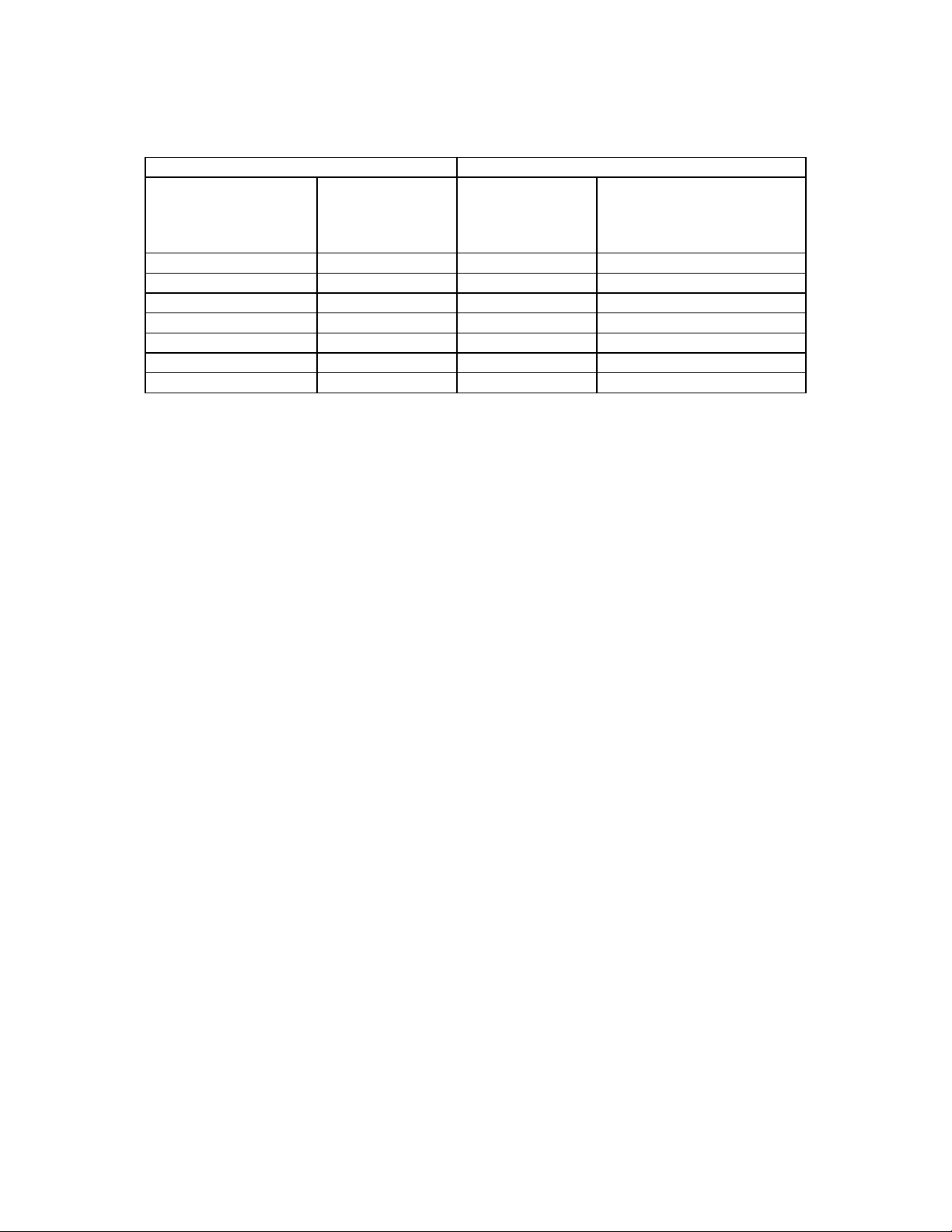
Table 3. Harmonic Distortion Accuracy
Test instrument Spectrum analyzer
Range MHz switch
setting
1 - 0.5 .5 400 K 2.6 M -30
2 - 1 1 900 K 5.1 M -30
4 - 2 2 1.9 M 11 M -30
8 - 4 4 3.9 M 21 M -30
16 - 8 8 7.9 M 41 M -30
32 - 16 16 15 M 81 M -30
64 - 32 32 31 M 161 M -30
128 - 64 64 63 M 321 M -30
256 - 128 128 127 M 640 M -30
512 - 256 256 250 M 1.3 G -30
512 - 256 512 500 M 2.6 G -30
Frequency MHz
display
(MHz)
START
FREQ
(Hz)
STOP
FREQ
(Hz)
MAX ∆MKR
indication
Harmonics ≥dB
below fundamental
NOTE
For TI’s containing option 002, perform (9) through (13) below.
For all others set RF OFF/ON switch to OFF and proceed to
paragraph 12 below.
(9) Press spectrum analyzer MARKER OFF, and repeat technique of (5) through (8)
above, using settings listed in table 3.
(10) Position controls as listed in (a) through (d) below.
(a) RANGE MHz switch to 1024-512 MHz.
(b) OUTPUT LEVEL switch to +10 dBm.
(c) RF OFF/ON switch to ON.
(d) COUNTER MODE EXPAND X10 pushbutton released.
(11) Adjust FREQUENCY TUNE control for a frequency MHz display indication of
1024 MHz and OUTPUT LEVEL vernier control(s) fully cw.
(12) Set spectrum analyzer to TI frequency, set power reference MARKER ON,
PEAK SEARCH, ∆MKR then tune to harmonic frequency listed in table 4. Harmonic
frequency ∆MKR indication will be within limits listed in table 4.
(13) Repeat technique of (10)(b), (11), and (12) above for remaining rows in table 4.
∆MKR indication will be within limits listed in table 4.
11
Page 12
TB 9-4931-488-35
Table 4. Harmonic Distortion Accuracy (TI Containing Option 002 Only)
Test instrument Spectrum analyzer
DATA Amplitude
(dBm)
+10 1024 2048 -12
+10 1024 3072 -12
+10 1024 4096 -12
+10 1024 5120 -12
+10 1024 2048 -12
1
-40
attenuation to0 dB.
1
-40 512 768 -20
Set OUTPUT LEVEL vernier for a meter reading of +3 dB, and set spectrum analyzer
DATA Frequency
(MHz)
512 256 -20
Harmonic
frequency
(MHz)
Limit
Tolerance
Harmonics ≥dB below
fundamental
(14) Set RF OFF/ON switch to OFF.
b. Adjustments. No adjustments can be made.
11. Output Level and Meter Accuracy (All Models Except Those Containing Option
004)
a. Performance Check
(1) Connect sensor module 11722A to measuring receiver CALIBRATION RF
POWER OUTPUT. Set measuring receiver to measure RF power, press RF Power CAL
and then save correction factors.
(2) Disconnect measuring receiver from CALIBRATION RF POWER OUTPUT
and connect to RF OUTPUT.
NOTE
The maximum output of TI's with option 002 is +13 dBm and
with options 002/003 is +12 dBm.
(3) Set OUTPUT LEVEL switch to +20 dBm and RANGE MHz switch to 512-256.
(4) Adjust FREQUENCY TUNE control for a 512 MHz indication on
FREQUENCY MHz display and press COUNTER MODE LOCK ON pushbutton.
(5) Set RF OFF/ON switch to ON.
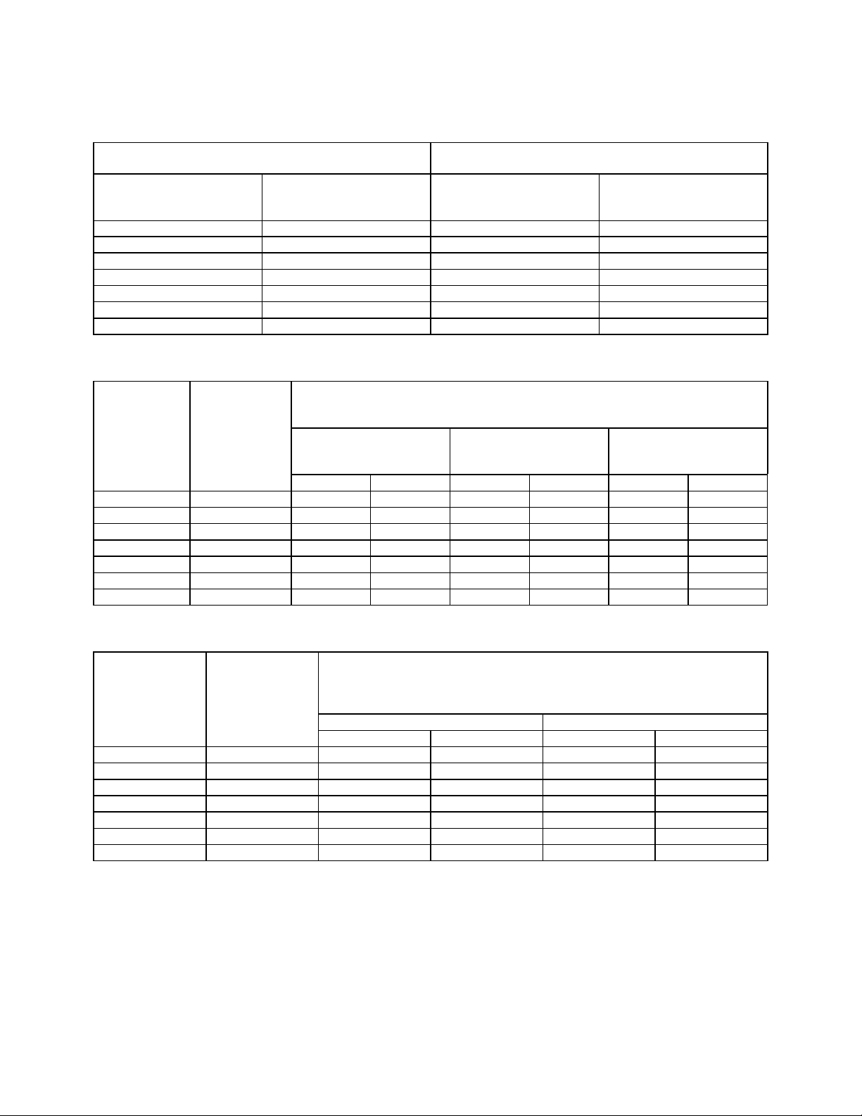
(6) Select the table (5 through 8) that corresponds to the appropriate option(s) of the
TI. Using the techniques of (3) and (4) above set OUTPUT LEVEL, RANGE MHz, and
FREQUENCY TUNE switches to settings listed in table selected and adjust OUTPUT
LEVEL vernier control(s) for meter indications as listed in table. If measuring receiver
indications are not as specified, perform b below
12
Page 13
TB 9-4931-488-35
Table 5. Output Meter Accuracy (Standard, Options 001 and H66)
Test instrument
OUTPUT LEVEL
switch settings
(dBm)
+20 -1 +17.5 +20.5
+20 -7 +11.5 +14.5
+20 -10 +8.5 +11.5
+10 +3 +11.5 +14.5
+10 0 +8.5 +11.5
0 +3 +1.5 +4.5
0 0 -1.5 +1.5
Test
instrument
OUTPUT
LEVEL
switch
settings
(dBm) Min Max Min Max Min Max
+20 -2 +16.5 +19.5 +16.0 +20.0 --- -- +20 -7 +11.5 +14.5 +11.0 +15.0 --- -- +20 -10 +8.5 +11.5 +8.0 +12.0 +7.0 +13.0
+10 +3 +11.5 +14.5 +11.0 +15.0 +10.0 +16.0
+10 0 +8.5 +11.5 +8.0 +12.0 +7.0 +13.0
0 +3 +1.5 +4.5 +1.0 +5.0 0.0 +6.0
0 0 -1.5 +1.5 -2.0 +2.0 -3.0 +3.0
Meter
indications
(dB)
Meter
indications
(dB)
Table 6. Output Meter Accuracy (Option 002)
Measuring receiver indications
25 MHz
Measuring receiver indications
(dBm)
Min
(dBm)
512 MHz
Max
1000 MHz
Table 7. Output Meter Accuracy (Option 002 with 003)
Test
instrument
OUTPUT
LEVEL
switch settings indications 25 And 512 MHz 1000 MHz
(dBm) (dB) Min Max Min Max
+20 -2 +15.0 +20.0 --- -- +20 -7 +10.0 +15.0 --- -- +20 -10 +6.5 +12.5 --- -- +10 +2 +9.0 +14.0 +8.5 +15.5
+10 0 +7.0 +12.0 +6.5 +13.5
0 +3 0.0 +5.0 -0.5 +6.5
0 0 -3.0 +2.0 -3.5 +3.5
Meter
Measuring receiver indications
(dBm)
13
Page 14
TB 9-4931-488-35
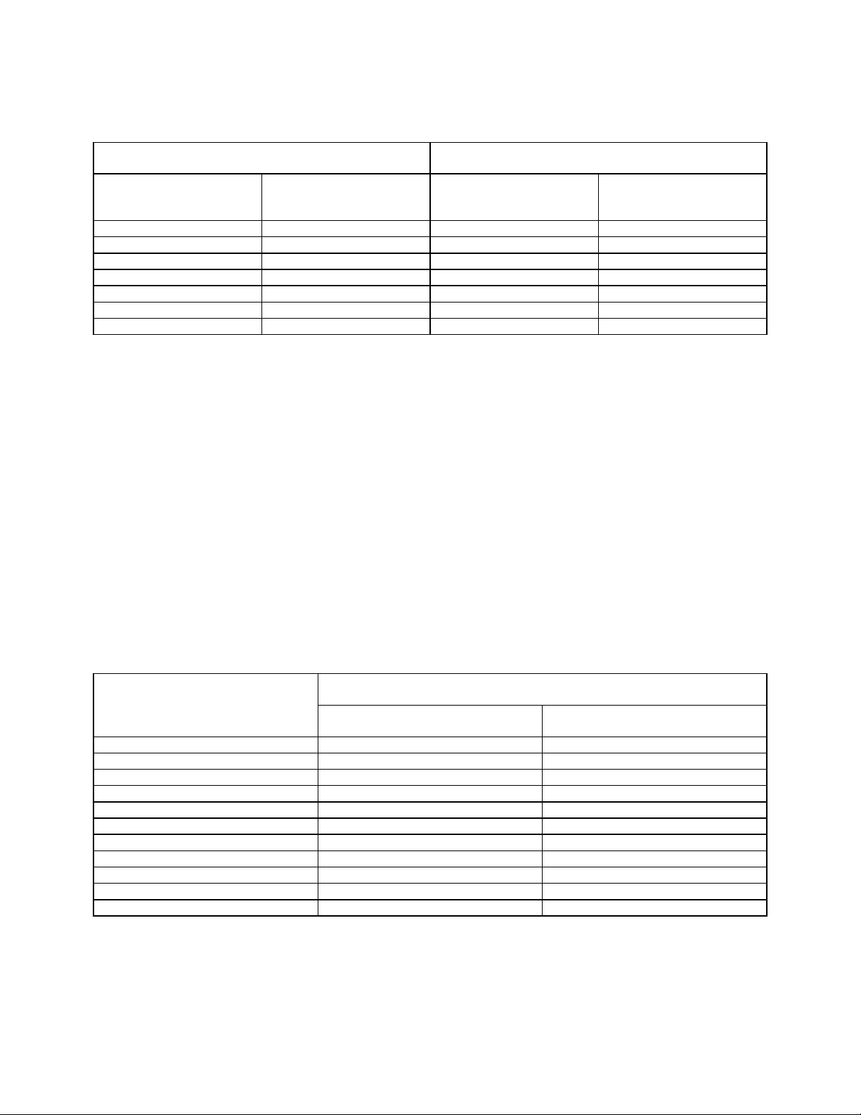
Table 8. Output Meter Accuracy (Option 003)
Test Instrument Measuring receiver Indications
(dBm)
OUTPUT LEVEL
switch settings
(dBm)
+20 -2 +15.75 +19.75
+20 -7 +10.75 +14.75
+20 -10 +7.75 +11.75
+10 +3 +10.75 +14.75
+10 0 +7.75 +11.75
+ 0 +3 +0.75 +4.75
+ 0 0 -2.25 +1.75
Meter
indications
(dB)
Min
Max
(7) Adjust OUTPUT LEVEL vernier control(s) for a 0.0-dBm measuring receiver
indication.
(8) Set measuring receiver to measure tuned level and press the RF Power CAL
button.
(9) Select the table (9 through 12) that corresponds to the appropriate option(s) of
the TI. Using the techniques of (3) and (4) above set OUTPUT LEVEL, RANGE MHz,
and FREQUENCY TUNE switches to settings listed in table selected and adjust
OUTPUT switch to settings listed in table selected. The measuring receiver will indicate
as specified.
NOTE
While performing the test in tables 9 through 11, press the
measuring receiver RF Power CAL button each time the
measuring receiver RCAL light illuminates.
Table 9. Output Level Accuracy (Basic, Option 001 and H66)
Test instrument
OUTPUT LEVEL
switch settings
(dBm)
-10 -12 -8
-20 -22 -18
-30 -32 -28
-40 -42 -38
-50 -52.5 -47.5
-60 -62.5 -57.5
-70 -72.5 -67.5
-80 -82.5 -77.5
-90 -92.5 -87.5
-100 -102.5 -97.5
-110 -112.5 -107.5
Measuring receiver indications
(dBm)
Min Max
14
Page 15
TB 9-4931-488-35
Table 10. Output Level Accuracy (Option 002)
Test
instrument
OUTPUT
LEVEL
switch
settings
(dBm)
-10 -12.0 -8.0 -12.5 -7.5 -13.5 -6.5
-20 -22.0 -18.0 -22.5 -17.5 -23.5 -16.5
-30 -32.0 -28.0 -27.5 -27.5 -33.5 -26.5
-40 -42.0 -38.0 -42.5 -37.5 -43.5 -36.5
-50 -52.5 -47.5 -53.0 -47.0 -54.0 -46.0
-60 -62.5 -57.5 -63.0 -57.0 -64.0 -56.0
-70 -72.5 -67.5 -73.0 -67.0 -74.0 -66.0
-80 -82.5 -77.5 -83.0 -77.0 -84.0 -76.0
-90 -92.5 -87.5 -93.0 -87.0 -94.0 -86.0
-100 -102.5 -97.5 -103.0 -97.0 -104.0 -96.0
-110 -112.5 107.5 -113.0 -107.0 -114.0 -106.0
Min
25 MHz
Max
Measuring receiver indications (dB)
Min
512 MHz
Max
Min
1000 MHz
Max
Table 11. Output Level Accuracy (Option 002 with 003)
Test
instrument
OUTPUT LEVEL
switch
settings
(dBm)
-10 -13.5 -7.5 -14.0 -6.0
-20 -23.5 -16.5 -24.0 -16.0
-30 -33.5 -27.5 -34.0 -26.0
-40 -43.5 -37.5 -44.0 -36.0
-50 -54.0 -47.0 -54.5 -45.5
-60 -64.0 -57.0 -64.5 -55.5
-70 -74.0 -67.0 -74.5 -65.5
-80 -84.0 -77.0 -84.5 -75.5
-90 -94.0 -87.0 -94.5 -85.5
-100 -104.0 -97.0 -104.5 -95.5
-110 -114.0 -107.0 -114.5 -105.5
25 and 512 MHz 1000 MHz
Min
Measuring receiver indications
(dB)
Max
Min
Max
15
Page 16
TB 9-4931-488-35
Table 12. Output Level Accuracy (Option 003)
Test instrument
OUTPUT LEVEL
switch settings
(dBm)
-10 -12.75 -7.75
-20 -22.75 -17.75
-30 -32.75 -27.75
-40 -42.75 -37.75
-50 -53.25 -47.25
-60 -63.25 -57.25
-70 -73.25 -67.25
-80 -83.25 -77.25
-90 -93.25 -87.25
-100 -103.25 -97.25
-110 -113.25 -107.25
Measuring receiver indications
(dB)
Min Max
(10) Release COUNTER MODE LOCK ON pushbutton.
b. Adjustments
(1) Position controls as listed in (a) through (d) below:
(a) AM X10% pushbutton pressed.
(b) AM switch to OFF.
(c) MODULATION FREQUENCY RANGE switch to FIXED FREQ 1 kHz.
(d) AM control fully ccw.
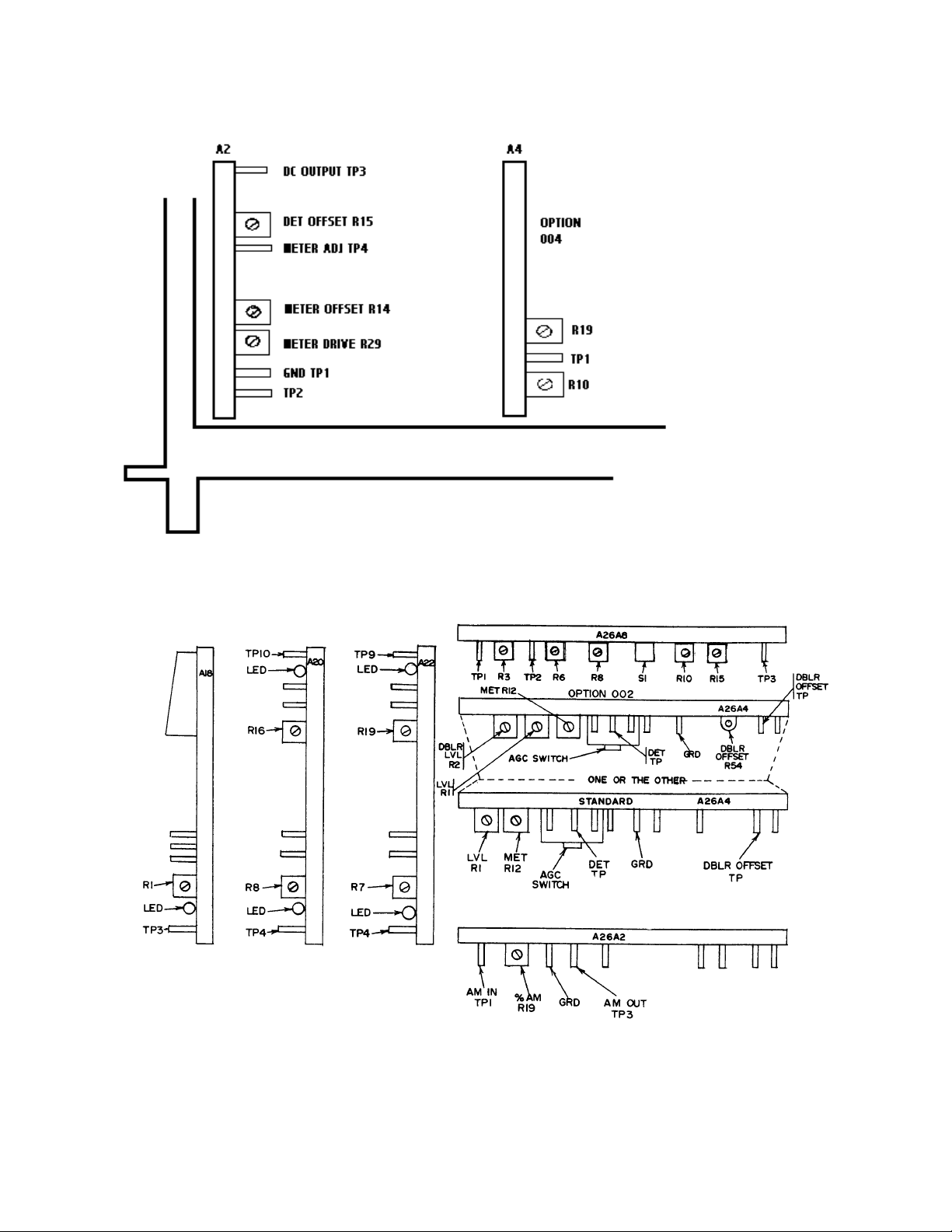
(2) Connect multimeter INPUT HI to DC OUTPUT A2TP3 (fig. 1) and INPUT LO
to GND A2TP1 (fig. 1). Adjust DET OFFSET A2R15 (fig. 1) for multimeter indication of
0.000 ±1 mV dc (R).
(3) Disconnect multimeter INPUT HI from DC OUTPUT A2TP3 and connect
INPUT HI to METER ADJ A2TP4 (fig. 1).
(4) Adjust METER OFFSET A2R14 (fig. 1) for multimeter indication of 0.000 ±1 mV
dc (R).
(5) Disconnect multimeter INPUT HI from METER ADJ A2TP4 (fig. 1) and connect
INPUT HI to AM IN A26A2TP1 (fig. 2).
16
Page 17
TB 9-4931-488-35
Figure 1. TEST instrument, top left hand side.
Figure 2. Test instrument - top back side.
17
Page 18
TB 9-4931-488-35
(6) Set AM switch to INT and adjust AM control for a multimeter indication of
0.707 V ac. Adjust METER DRIVE A2R29 (fig. 1) for TI meter indication of 10 on 0 to 10
scale (R).
(7) Adjust AM control for TI meter indications listed in table 13. Multimeter will
indicate as specified; if not, readjust METER DRIVE A2R29 (fig. 1) for best in-tolerance
condition.
Table 13. Meter Accuracy
Test instrument meter
indications
(0 - 10 Scale)
7 0.487 0.503
5 0.345 0.362
3 0.205 0.220
10 0.697 0.718
Min Max
Multimeter indications
(V Rms)
(8) Disconnect multimeter from TI. Connect RF OUTPUT to measuring receiver
sensor module.
(9) Position controls as listed in (a) through (i) below.
(a) LEVEL VOLTS pushbutton pressed.
(b) AM control fully ccw.
(c) FM switch to OFF.
(d) COUNTER MODE LOCK ON released.
(e) RANGE MHz switch 64-32.
(f) FREQUENCY TUNE control for a FREQUENCY MHz display indication of
50 MHz.
(g) OUTPUT LEVEL switch to +10 dBm.
(h) OUTPUT LEVEL vernier control(s) fully cw.
(i) RF OFF/ON switch to ON.
(10) Set measuring receiver to measure AM with AVG DETECTOR.
(11) Adjust AM control for a measuring receiver indication of approximately 20%.
Press measuring receiver RATIO % key.
(12) Adjust OUTPUT LEVEL vernier control(s) for a TI meter indication of -7dB.
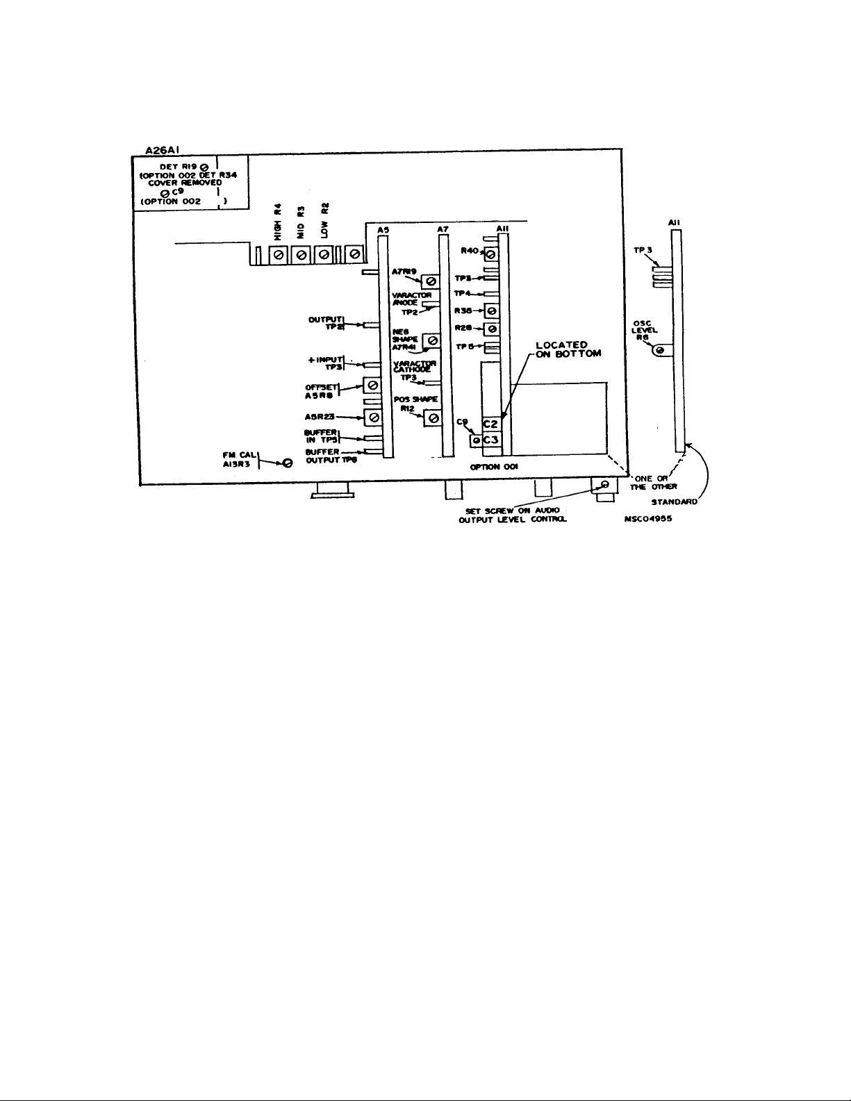
(13) Adjust DET A26A1R19 (A26A1R34 for option 002) (fig. 3) for measuring receiver
indication of 100% (R).
18
Page 19
TB 9-4931-488-35
Figure 3. TEST instrument - bottom view.
(14) Set OUTPUT LEVEL vernier control(s) fully cw.
(15) Measuring receiver will indicate between 99.5 and 100.5%, if not, repeat (11)
through (14) above while readjusting A26A1R19 (A26A1R34 for option 002) (fig. 3) for best
in-tolerance condition.
(16) Set AM switch to OFF.
(17) Set measuring receiver to measure RF power.
(18) For option 002 only, set DBLR OFFSET A26A4R54 (fig. 2) to mid-range.
(19) Adjust LVL A26A4R1 (fig. 2) for a +13.2 dBm measuring receiver indication (R).
(20) Adjust OUTPUT LEVEL vernier control(s) for a +13.0 dBm measuring receiver
indication. Adjust MET A26A4R12 (fig. 2) for TI meter indication of +3 dB (R).
(21) For option 002, proceed to (22) below. For all other models, repeat a above.
(22) Set RANGE MHz switch to 1024-512 and adjust FREQUENCY TUNE control
for FREQUENCY MHz display indication of 800 MHz.
(23) Adjust DBLR LVL A26A4R2 (fig. 2) for a +13.0 dBm measuring receiver
indication (R).
19
Page 20

TB 9-4931-488-35
(24) Set RANGE MHz switch to 64-32 and FREQUENCY TUNE for 50-MHz
display indication. Adjust OUTPUT LEVEL vernier control ccw for a +3-dBm measuring
receiver indication.
(25) Set RANGE MHz switch to 1024-512. Adjust DBLR OFFSET A26A4R54 (fig. 2)
for a +3 dBm measuring receiver indication (R).
(26) Set RANGE MHz switch to 64-32 and adjust OUTPUT LEVEL vernier control
fully cw. If measuring receiver does not indicate +13.2 dBm, repeat (19) above.
(27) Repeat (20) through (26) above until measuring receiver indication at 800 MHz is
within ±.2 dBm of the 50 MHz indication.
(28) Set RANGE MHz switch to 1024-512 and adjust FREQUENCY TUNE control
for FREQUENCY MHz display indication of 700 MHz.
(29) Set OUTPUT LEVEL switch to +20 dBm and set OUTPUT LEVEL vernier
control(s) fully cw. Adjust A26A1C9 (fig. 3) for maximum measuring receiver indication
(not to exceed +17 dBm) (R).
(30) Position controls as listed in (a) through (e) below.
(a) AM 10X pushbutton pressed.
(b) AM switch to AC.
(c) AM control fully cw.
(d) OUTPUT LEVEL switch to +10 dBm.
(e) FREQUENCY TUNE control for FREQUENCY MHz display indication of
800 MHz.
(31) Adjust OUTPUT LEVEL vernier control(s) for a 0 dB indication on TI meter.
(32) Connect equipment as shown in figure 4.
Figure 4. Doubler gain - adjustment setup
20
Page 21

TB 9-4931-488-35
(34) Set pulse generator controls for a 0.5 ms pulse width with a 1 kHz rate. Adjust
pulse generator output controls for TI meter indication of 40% (4 on 0-10 scale).
NOTE
REDUCE PEAK POWER anunciator should be off in (35) and
(36) below.
(35) Adjust oscilloscope controls as necessary to display detected RF output signal.
Readjust A26A1C9 (fig. 3) slightly (if required) to limit ringing and eliminate oscillations as
indicated on oscilloscope display.
(36) While observing oscilloscope display, slowly vary TI frequency from 512 to 1024
MHz. Readjust A26A1C9 (fig. 3) for a stable square wave indication on oscilloscope display.
(37) Repeat (21) through (36) above until no further adjustment is necessary.
(38) Repeat a above.
12. Output Level and Meter Accuracy (Models Containing Option 004)
a. Performance Check
(1) Connect measuring receiver to RF OUTPUT.
(2) Position controls as listed in (a) through (c) below:
(a) RANGE MHz switch to 512-256.
(b) OUTPUT LEVEL 10 dB switch to +16 dBm.
(c) OUTPUT LEVEL 1 dB switch to 0 dBm.
(3) Adjust FREQUENCY TUNE control for a 512 MHz indication on
FREQUENCY MHz display, and press LOCK ON pushbutton.
(4) Set RF OFF/ON switch to ON
NOTE
In (5) and (6) below, the OUTPUT LEVEL 1 dB switch
position must be changed, as necessary, to obtain required TI
meter indications.
(5) Adjust OUTPUT LEVEL controls for a TI meter indication of -5 dB. Measuring
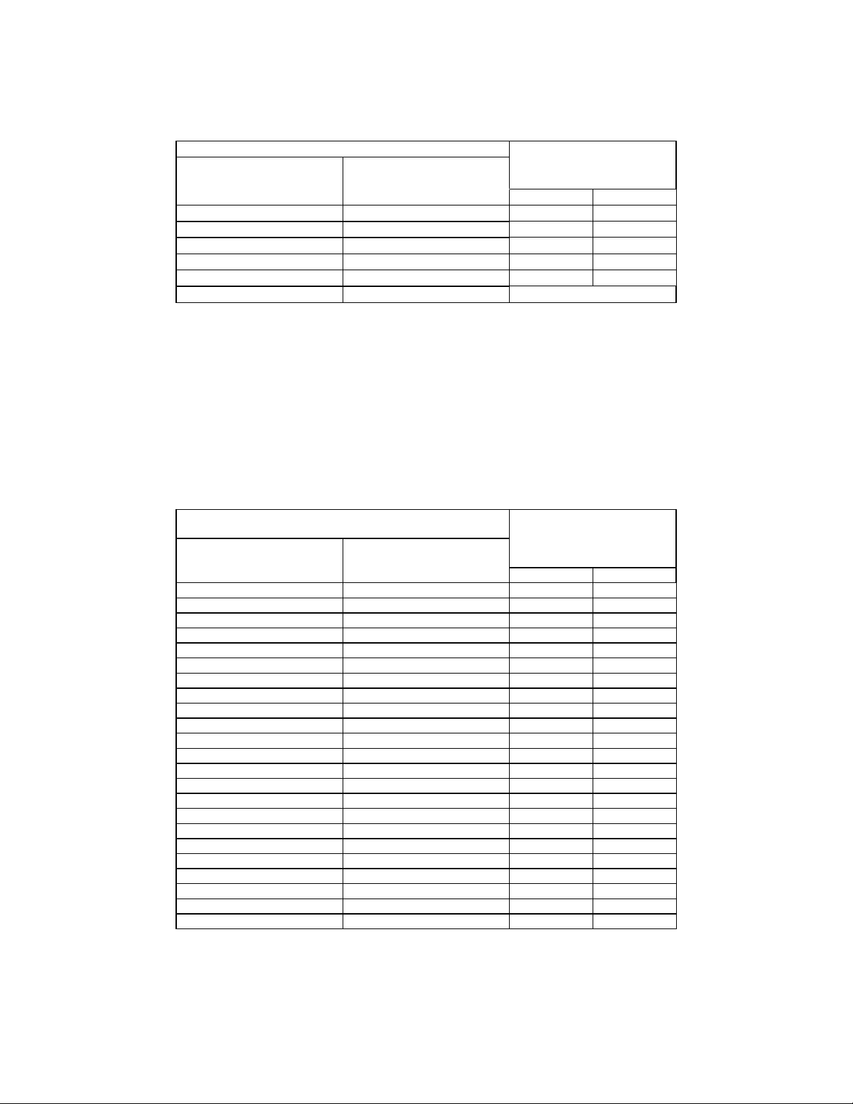
receiver will indicate between +13.5 and +16.5 dB as listed in table 14; if not, perform b
below.
(6) Repeat technique of (5) above for OUTPUT LEVEL 10 dBm switch settings and
meter indications listed in table 14. Measuring receiver will indicate as specified; if not,
perform b below.
21
Page 22
TB 9-4931-488-35
Table 14. Output Meter Accuracy (Option 004)
Test Instrument Measuring receiver
OUTPUT LEVEL
10 dbm
switch settings
+16 -5 +13.5 +16.5
+16 -7 +11.5 +14.5
+16 -10 +8.5 +11.5
+10 0 +8.5 +10.5
+10 -1 +7.5 +10.5
0 0 -1.5 +1.5
Meter
indications
(dB)
indications
(dBm)
Min Max
(7) Set OUTPUT LEVEL 1 dB switch to 0 dB and adjust OUTPUT LEVEL
vernier control for a 0 dBm TI meter indications.
(8) Set measuring receiver to measure tuned level at 512 MHz then establish a 0.0
dB reference on measuring receiver.
(9) Set OUTPUT LEVEL 10 dB switch to -10 dBm. Measuring receiver will
indicate between minimum and maximum limits listed in table 15.
(10) Repeat technique of (9) above for OUTPUT LEVEL switch positions listed in
table 15. Receiver system will indicate as specified.
Table 15. Output Level Accuracy (Option 004)
Test Instrument
OUTPUT LEVEL
10 dB
switch settings switch settings Min Max
-10 0 -12.0 -8.0
-10 -1 -13.0 -9.0
-10 -2 -14.0 -10.0
-10 -3 -15.0 -11.0
-10 -4 -16.0 -12.0
-10 -5 -17.0 -13.0
-10 -6 -18.0 -14.0
-10 -7 -19.0 -15.0
-10 -8 -20.0 -16.0
-10 -9 -21.0 -17.0
-10 -10 -22.0 -18.0
-10 -11 -23.0 -19.0
-10 -12 -24.0 -20.0
-20 0 -22.0 -18.0
-30 0 -32.0 -28.0
-40 0 -42.0 -38.0
-50 0 -52.5 -47.5
-60 0 -62.5 -57.5
-70 0 -72.5 -67.5
-80 0 -82.5 -77.5
-90 0 -92.5 -87.5
-100 0 -102.5 -97.5
-110 0 -112.5 -107.5
OUTPUT LEVEL
1 dB
Measuring receiver
indications
(dB)
22
Page 23

TB 9-4931-488-35
(11) Release COUNTER MODE LOCK ON pushbutton and set RF OUTPUT
OFF/ON switch to OFF.
b. Adjustments
(1) Position controls as listed in (a) through (f) below.
(a) FM k/MHz pushbutton pressed.
(b) MODULATION FREQUENCY RANGE switch to FIXED FREQ 1 kHz.
(c) FM switch to OFF.
(d) PEAK DEVIATION switch to 10 kHz.
(e) PEAK DEVIATION vernier control fully ccw.
(f) RANGE MHz switch to 4-2.
(2) Connect multimeter to A2TP2 (fig. 1) and chassis ground. Adjust DET OFFSET
A2R15 (fig. 1) for a 0.000 ±1-mV dc multimeter indication (R).
(3) Disconnect multimeter from A2TP2 and connect to A4TP1 (fig. 1). Adjust A4R10
(fig. 1) for a 0.000 ±1 mV dc multimeter indication (R).
(4) Set FM switch to INT and adjust PEAK DEVIATION vernier control for a
9.766 V dc multimeter indication.
(5) Adjust A4R19 (fig. 1) for a TI meter indication of 10 on 0 to 10 scale (R).
(6) Position controls as listed in (a) through (g) below:
(a) LEVEL VOLTS pushbutton pressed.
(b) AM switch to INT.
(c) AM control fully ccw.
(d) RANGE MHz switch to 256-128.
(e) FREQUENCY TUNE control for FREQUENCY MHz display indication of
190 MHz.
(f) OUTPUT LEVEL vernier control to CAL.
(g) OUTPUT LEVEL switches to +10 dBm.
(7) Disconnect multimeter from TI and connect RF OUTPUT to measuring receiver
input and set
(8) Set measuring receiver to measure AM with AVG DETECTOR.
(9) Adjust AM control for a measuring receiver indication of approximately 20%.
Press measuring receiver RATIO % key.
(10) Set OUTPUT LEVEL switches to 0 dBm. Adjust DET A26A1R19 (fig. 3) for a
measuring receiver indication of 100% (R).
(11) Set OUTPUT LEVEL switches to +10 dBm. Measuring receiver will indicate
between 99.5 and 100.5%; if not, repeat (9) and (10) above while adjusting A26A1R19 (fig.
1) for best in-tolerance condition.
(12) Set measuring receiver to measure RF power.
RF OFF/ON switch to ON.
23
Page 24

TB 9-4931-488-35
(13) Position controls as listed in (a) through (d) below.
(a) AM switch to OFF.
(b) RANGE MHz switch to 64-32.
(c) FREQUENCY TUNE control for FREQUENCY MHz display indication of
50 MHz.
(d) OUTPUT LEVEL vernier control to CAL.
(14) Set OUTPUT LEVEL 10 dB switch to +16 dBm and 1 dB switch to -3 dB.
(15) Adjust LVL A26A4R1 (fig. 2) for a +13 dBm indication on measuring receiver
(R).
(16) Adjust MET A26A4R12 (fig. 2) for a –7 dB indication on TI meter (R).
(17) Repeat ((15) and (16) above for best in tolerance condition.
13. Output Level Flatness
a. Performance Check
(1) Position controls as listed in (a) through (e) below.
(a) LEVEL VOLTS pushbutton pressed.
(b) AM switch to OFF.
(c) FM switch to OFF.
(d) RF OFF/ON switch to OFF.
(e) OUTPUT LEVEL switch to +10 dBm.
(2) Connect measuring receiver with power senor to RF OUTPUT.
NOTE
For TI models containing opt 004 proceed to (7) below.
(3) Set RANGE MHz switch to 64-32 and adjust FREQUENCY TUNE control for a
50 MHz indication on FREQUENCY MHz display.
(4) Set RF OFF/ON switch to ON and adjust OUTPUT LEVEL vernier control(s)
for a +8.0 dBm indication on measuring receiver.
(5) While observing measuring receiver indication, slowly vary TI frequency from
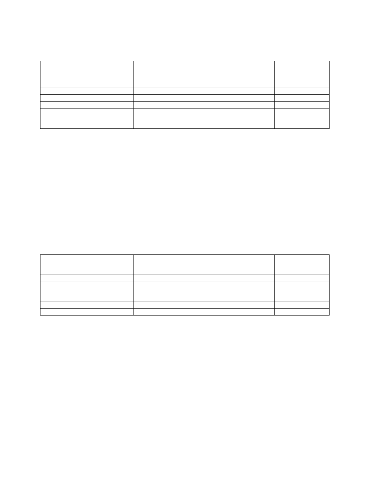
start to stop frequencies listed in table 16. Measuring receiver will indicate between
minimum and maximum indications listed in table 16.
(6) Repeat technique of (3) through (5) above for remaining options and settings
listed in table 16.
24
Page 25
TB 9-4931-488-35
Table 16. Output level flatness (models without option 004).
Options Start
frequency
(Hz)
Standard model 001, H66 16 M 512 M +7.5 +8.5
003 16 M 512 M +6.75 +8.75
002 16 M 64 M +7.25 +8.25
002 64 M 512 M +7.0 +9.0
002 512 M 1000 M +6.5 +9.5
002 with 003 16 M 512 M +6.0 +9.0
002 with 003 512 M 1000 M +6.0 +10.0
Stop
frequency
(Hz)
Min
indication
(dB)
Max
indication
(dB)
NOTE
Perform (7) through 10 below for models containing
opt 004 only. All other models proceed to (11) below.
(7) Set RANGE MHz switch to 256-128 and adjust FREQUENCY TUNE control
for a 190 MHz indication on FREQUENCY MHz display.
(8) Set RF OFF/ON switch to ON and adjust OUTPUT LEVEL 1 dB switch and
vernier control for a +8.0 dBm indication on measuring receiver.
(9) While observing measuring receiver indication, slowly vary TI frequency from
start to stop frequencies listed in table 17. Measuring receiver will indicate between
minimum and maximum indications listed in table 17.
(10) Repeat technique of (7) through (9) above for remaining options and settings
listed in table 17.
Table 17. Output level flatness models contain option 004
Options Start
frequency
(Hz)
004 16 M 108 M +7.25 +8.75
004 108 M 336 M +7.5 +8.5
004 336 M 512 M +7.25 +8.75
004 with 003 16 M 108 M +6.75 +9.25
004 with 003 108 M 336 M +7.5 +8.5
004 with 003 336 M 512 M +6.75 +9.25
Stop
frequency
(Hz)
Min
indication
(dB)
Max
indication
(dB)
(11) Disconnect measuring receiver from TI.
b. Adjustments. No adjustments can be made.
14. Internal Modulation Oscillator Frequency Accuracy, Output Voltage, and
Distortion
a. Performance Check
(1) Position controls as listed in (a) through (f) below.
25
Page 26

TB 9-4931-488-35
(a) AM switch to INT.
(b) AUDIO OUTPUT LEVEL control fully cw.
(c) AM vernier fully cw.
(d) MODULATION FREQUENCY RANGE switch to FIXED FREQ 1 kHz
(1000 Hz for opt 004).
(e) RF OFF/ON switch to ON.
(f) FM switch to OFF.
(2) Connect audio analyzer to AM OUTPUT using 600-Ω termination.
(3) Set audio analyzer and TI to the first functions and settings listed in table 18.
(4) Audio analyzer will indicate within limits specified in table 18.
(5) Set audio analyzer and TI to the remaining functions and settings listed in table
18 and repeat (4) above.
Table 18. Internal Modulation Oscillator Frequency Accuracy and Distortion
Test instrument Audio analyzer
Modulation frequency
range switch settings
FIXED FREQ 1 kHz ---------- Level ---------- 1 (3)
FIXED FREQ 1 kHz ---------- Frequency ---------- ---------- 970 1030
FIXED FREQ 1 kHz ---------- Distortion 0.5% ---------- ---------- ---------FIXED FREQ 400 Hz ---------- Frequency ---------- ---------- 388 412
FIXED FREQ 400 Hz ---------- Distortion 0.5% ---------- ---------- ----------
1
Values in parenthesis are for option 001.
2
Perform remaining test only for TI’s containing option 001 & H66
3
Replace audio analyzer with frequency counter before this measurement.
2
X1
X1 100 Distortion 0.5% ---------- ---------- ---------X1 20 Frequency ---------- ---------- 17 23
X1 20 Distortion 0.5% ---------- ---------- ---------X10 100 Frequency ---------- ---------- 850 1150
X10 100 Distortion 0.5% ---------- ---------- ---------X10 200 Frequency ---------- ---------- 1700 2300
X10 200 Distortion 1.0% ---------- ---------- ----------
X100 200 Frequency ---------- ---------- 17,000 23,000
X100 200 Distortion 1.0% ---------- ---------- ---------X100 100 Frequency ---------- ---------- 8,500 11,500
X100 100 Distortion 1.0% ---------- ---------- ----------
X1K 100 Frequency ---------- ---------- 85,000 115,000
X1K 100 Distortion 1.0% ---------- ---------- ----------
3
X1K
X3K 200 Frequency ---------- ---------- 510,000 690,000
X3K 20 Frequency ---------- ---------- 51,000 69,000
Modulation
frequency
vernier
100 Frequency ---------- ---------- 85 115
200 Frequency ---------- ---------- 170,000 230,000
Function Distortion
indication
≤
Volts
indication
>
1
Frequency
Minimum Maximum
---------- ----------
b. Adjustments. For TI's containing options 001 & H66, perform (3) through (19)
below. For all other TI's, perform (1) and (2) below.
26
Page 27

TB 9-4931-488-35
(1) Connect true rms voltmeter to A11TP3 (fig. 3) and chassis ground. Adjust OSC
LEVEL A11R6 (fig. 3) for true rms voltmeter indication of 0.840 ±0.010 V ac (R).
(2) Repeat a (3) through (5) above.
(3) Set MODULATION FREQUENCY RANGE switch to X100 and adjust
MODULATION FREQUENCY vernier dial fully ccw.
(4) Connect true rms voltmeter INPUT to A11TP4 (fig. 3) and chassis ground.
Adjust A11R28 (fig. 3) for a 1.4-V ac true rms voltmeter indication. Record true rms
voltmeter indication (R).
(5) Connect frequency counter CHANNEL A input to TI AM OUTPUT. Adjust
MODULATION FREQUENCY vernier dial fully cw.
(6) Adjust A11C2 and A11C3 (fig. 3) until true rms voltmeter indicates within ± 0.1
V ac of value recorded in (4) above (R).
NOTE
Adjusting A11C2 (fig. 3) ccw decreases voltage while increasing
frequency. Adjusting A11C3 (fig. 3) ccw increases both voltage
and frequency.
(7) Adjust MODULATION FREQUENCY vernier dial to 20. If frequency counter
does not indicate 2.00 ±0.02 kHz, adjust vernier dial for a 2.00 kHz frequency counter
indication. Loosen setscrews in vernier control shaft gear and position vernier dial to 20.
Tighten setscrews and, if necessary, readjust A11R28 (fig. 3) for true rms voltmeter
indication between 1.37 and 1.48 V ac. Record true rms voltmeter indication.
(8) Adjust MODULATION FREQUENCY vernier dial to 200. If true rms
voltmeter does not indicate within ±0.01 V ac of value recorded in (7) and frequency counter
indication is not 20 ±0.2 kHz, readjust A11C2 (fig. 3) and A11C3 (fig. 3) for desired
indications.
(9) Adjust MODULATION FREQUENCY vernier dial to 20. If true rms voltmeter
does not indicate within ±0.01 V ac of value recorded in (7) above and frequency counter
indication is not 2.00 ±0.02 kHz, repeat (7) and (8) above.
(10) Adjust MODULATION FREQUENCY vernier dial to 20. True rms voltmeter
will indicate between 1.37 and 1.48 V ac. Record true rms voltmeter indication.
(11) While observing true rms voltmeter indication, slowly vary TI modulation
frequency from 2 kHz to 20 kHz. True rms voltmeter will indicate within ±0.03 V ac of
indication recorded in (10) above.
(12) Set MODULATION FREQUENCY RANGE switch to X3K and adjust
MODULATION FREQUENCY vernier dial to 200. Adjust A11C9 (fig. 3) for a 600 ±6kHz
frequency counter indication (R).
(13) Position controls as listed in (a) through (c) below.
27
Page 28
TB 9-4931-488-35
(a) FM switch to INT.
(b) MODULATION FREQUENCY RANGE switch to X100.
(c) MODULATION FREQUENCY vernier dial to 20.
(14) Connect true rms voltmeter INPUT to A11TP5 (fig. 3) and chassis ground.
Adjust A11R35 (fig. 3) for a 0.840 ±0.010 V ac true rms voltmeter indication. Record true
rms voltmeter indication (R).
(15) Disconnect true rms voltmeter from A11TP5 (fig. 3) and connect to A11TP3 (fig.
3). True rms voltmeter will indicate within ±0.005 V ac of value recorded in (14) above.
(16) While observing true rms voltmeter, slowly vary modulation frequency from 20
Hz to 100 kHz. True rms voltmeter will indicate within ±0.025 V ac of value recorded in
(14) above.
(17) Repeat technique of (16) for 100 to 600 kHz. True rms voltmeter will indicate
within ±0.050 V ac of value recorded in (14) above.
(18) Set MODULATION FREQUENCY RANGE switch to X3K and adjust
MODULATION FREQUENCY vernier dial to 20.
(19) Disconnect frequency counter and true rms voltmeter from TI. Connect true rms
voltmeter to AM OUTPUT, using 600 Ω termination. Adjust A11R40 (fig. 3) for 3.10 ±0.03
V ac true rms voltmeter indication (R).
(20) Disconnect equipment setup.
15. AM Sensitivity, Accuracy, and Distortion (All Models Except Those Containing
Option 004)
a. Performance Check
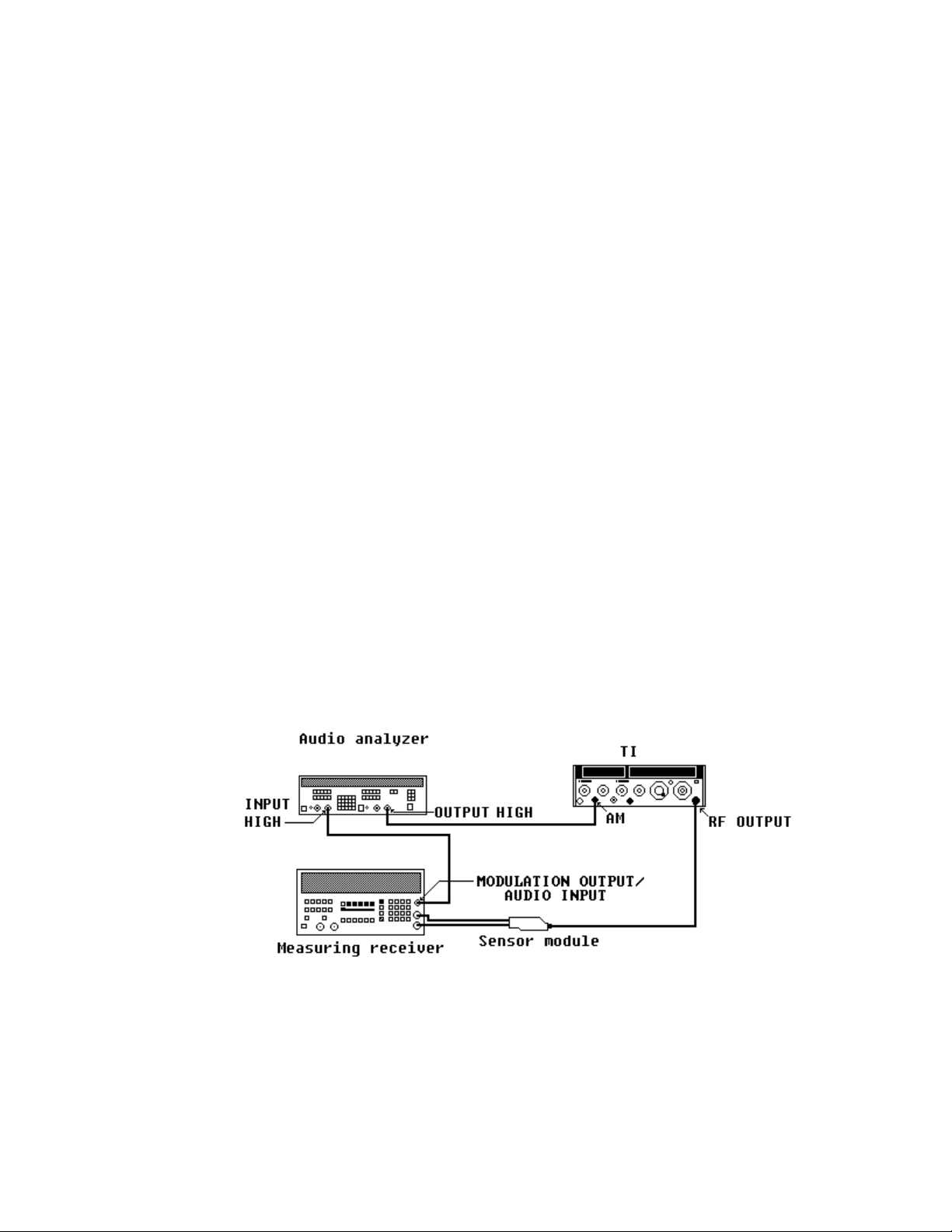
(1) Connect equipment as shown in figure 5.
Figure 5. AM test setup.
28
Page 29
TB 9-4931-488-35
(2) Position controls as listed in (a) through (k) below.
(a) COUNTER MODE INT EXT pushbutton pressed.
(b) COUNTER MODE EXPAND X10 and X100 pushbuttons released.
(c) COUNTER MODE LOCK ON pushbutton released.
(d) AM X10% pushbutton pressed.
(e) AM switch to DC.
(f) AM control fully cw.
(g) FM switch to OFF.
(h) RANGE MHz switch to 512-256.
(i) FREQUENCY TUNE control for a FREQUENCY MHz display indication of
500 MHz.
(j) OUTPUT LEVEL switch to +10 dBm and vernier control(s) fully cw.
(k) RF OFF/ON switch to ON.
(3) Set measuring receiver to acquire the frequency then to measure AM with peak
+ detector. Set high-pass filter to 50 Hz and low-pass filter to 15 kHz
(4) Set audio analyzer controls for a 1 kHz 600 Ω output frequency.
NOTE
In (5) and (8) below, record measuring receiver % AM display
indication using peak + detector and peak - detector. Average
the indications and use the average for determining the
results.
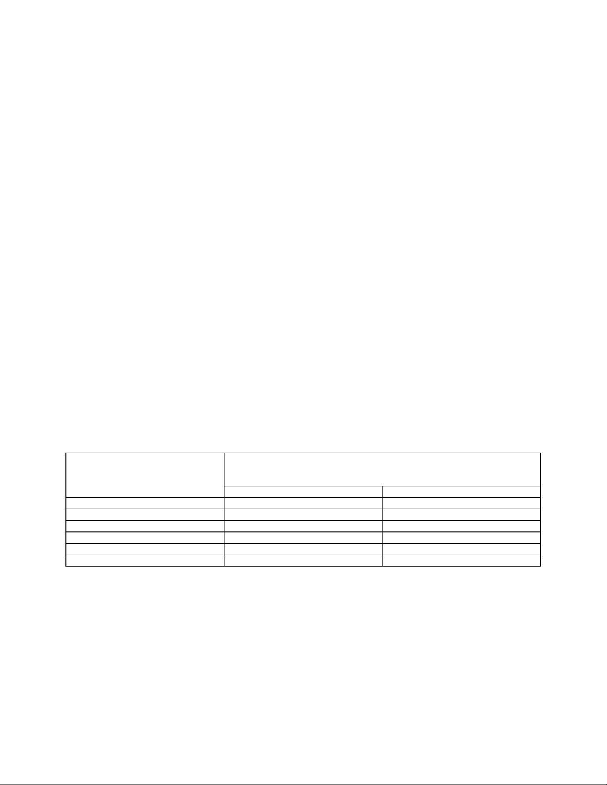
(5) Adjust audio analyzer output controls for a 1.272-V level. The measuring
receiver will indicate between min and max limits listed in table 19; if not, perform b below.
(6) Repeat technique of (5) above for audio analyzer output levels listed in table 19.
The measuring receiver will indicate as specified; if not, perform b below.
Table 19. AM Sensitivity
Audio analyzer
Output
levels
(V ac) Min Max
1.272 85.5 94.5
.9898 66.5 73.5
.707 47.5 52.5
.4242 28.5 31.5
.2828 19.0 21.0
.1414 9.5 10.5
Measuring receiver
Indications
(% AM)
(7) Adjust audio analyzer output controls for a 1.414-V level.
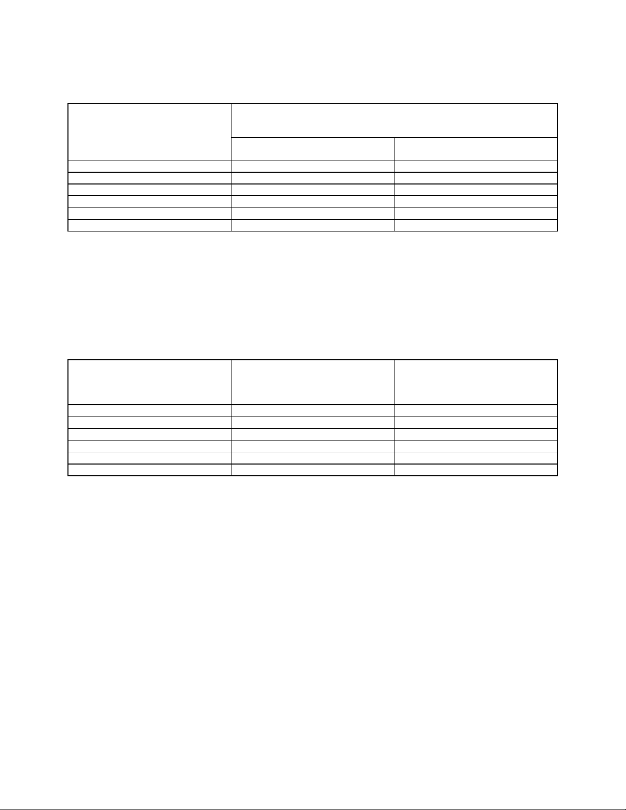
(8) Adjust AM control for 90 % modulation (9 on 0-10 scale) as indicated on TI
meter. The measuring receiver will indicate between min and max limits listed in table 20.
(9) Repeat technique of (8) for TI meter indications listed in table 20. The
modulation analyzer will indicate as specified.
29
Page 30
TB 9-4931-488-35
Table 20. AM Accuracy
Test
Instrument
Meter
Indications
90 83.6 96.5
70 64.7 75.4
50 45.8 54.3
30 26.9 33.2
20 17.4 22.6
10 7.95 12.1
Min Max
Measuring receiver
Indications
(% AM)
(10) Press LEVEL VOLTS pushbutton and adjust OUTPUT LEVEL vernier
control(s) for a +3 dB indication on TI meter.
(11) Adjust AM control for a 50% AM indication on measuring receiver. The
distortion, as indicated on the audio analyzer will be within limits listed in table 21.
(12) Repeat technique of (10) and (11) above for TI meter dB indications and
measuring receiver % AM indications listed in table 21. The audio analyzer distortion
indications will be as specified.
Table 21. AM Distortion
Test instrument
meter indications
(dB)
+3 50 1
+3 90 3
-7 90 3
-7 50 1
-71 30 10
1
Perform for option 002 only. Set RANGE MHz switch to 1024-512 and adjust FREQUENCY TUNE control for a
FREQUENCY MHz display indication of 1024 MHz.
-71 90 20
Measuring receiver
indications
(% AM)
Audio
analyzer
indications
(<%)
b. Adjustments
(1) Position controls as listed in (a) through (f) below.
(a) AM switch to AC.
(b) AM control fully cw.
(c) OUTPUT LEVEL vernier control(s) fully cw.
(d) RANGE MHz switch to 64-32.
(e) FREQUENCY TUNE control for FREQUENCY MHz display indication of
50 MHz.
(f) RF OFF/ON switch to ON.
(2) Set Audio analyzer for a 1 kHz .7072 V 600 Ω output signal.
30
Page 31

TB 9-4931-488-35
(3) Set measuring receiver to measure peak AM with 50 Hz high-pass and 15 kHz
low-pass filters. Adjust %AM A26A2R19 (fig. 2) for a 50.0 ±0.1% measuring receiver
indication (R).
(4) Set AM and RF OFF/ON switches to OFF and repeat a above.
16. AM Sensitivity, Accuracy, Distortion, and Demodulated Output (Models
Containing Option 004)
a. Performance Check
(1) Connect equipment as shown in figure 5.
(2) Position controls as listed in (a) through (m) below.
(a) COUNTER MODE INT EXT pushbutton pressed.
(b) COUNTER MODE EXPAND X10 and X100 pushbuttons released.
(c) COUNTER MODE LOCK ON pushbutton released.
(d) AM X10% pushbutton pressed.
(e) AM switch to DC.
(f) AM control fully cw.
(g) FM switch to OFF.
(h) RANGE MHz switch to 512-256.
(i) FREQUENCY TUNE control for FREQUENCY MHz display indication of
500 MHz.
(j) OUTPUT LEVEL 10 dB switch to +10 dBm.
(k) OUTPUT LEVEL 1 dB switch to 0 dBm.
(l) OUTPUT LEVEL vernier control fully cw.
(m) RF OFF/ON switch to ON.
(3) Set measuring receiver to measure AM with peak + detector. Set high-pass filter
to 50 Hz and low-pass filter to 15 kHz.
(4) Adjust audio analyzer controls for a 1 kHz, 600 Ω output frequency.
NOTE
In (5) and (8) below, record measuring receiver % AM display
indication using peak + detector and peak - detector. Average
the indications and use the average for determining the
results.
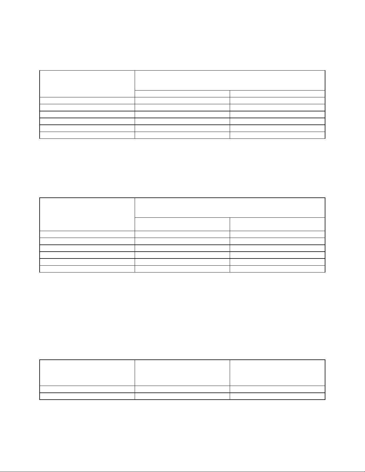
(5) Adjust audio analyzer output controls for a 0.827-V level. The measuring
receiver will indicate between min and max limits listed in table 22; if not, perform
(6) Repeat technique of (5) above for audio analyzer output levels listed in table 22.
The measuring receiver will indicate as specified; if not, perform b below.
b below.
31
Page 32
TB 9-4931-488-35
Table 22. OPT 004 AM Sensitivity
Audio analyzer
output
levels
(V ac) Min Max
0.827 85.5 94.5
0.643 66.5 73.5
0.459 47.5 52.5
0.276 28.5 31.5
0.184 19.0 21.0
0.092 9.5 10.5
Measuring receiver
indications
(% AM)
(7) Adjust audio analyzer OUTPUT controls for a 1.000 V level.
(8) Adjust AM control for 90% modulation (9 on 0-10 scale) as indicated on TI meter.
The measuring receiver will indicate between min and max limits listed in table 23.
(9) Repeat technique of (8) above for TI meter indications listed in table 23. The
measuring receiver will indicate as specified.
Table 23. OPT 004 AM Accuracy
Test
instrument
meter
indications
90 83.6 96.5
70 64.7 75.4
50 45.8 54.3
30 26.9 33.2
20 17.4 22.6
10 7.95 12.1
Min
Measuring receiver
indications
(% AM)
Max
(10) Press LEVEL VOLTS pushbutton. Set OUTPUT LEVEL 10 dB switch to +10
dBm and 1 dB switch to -7 dB. Adjust OUTPUT LEVEL vernier control for a -7dB
indication on TI meter.
(11) Adjust AM control for a 50% AM indication on measuring receiver. The
distortion, as indicated on the audio analyzer will be within limits listed in table 24.
(12) Repeat technique of (10) and (11) above for TI meter dB indications and
measuring receiver % AM indications listed in table 24. The audio analyzer indications will
be as specified.
Table 24. OPT 004 AM Distortion
32
Test instrument
meter indications
(dB)
-7 50 1
-7 90 3
Measuring receiver
indications
(% AM)
Audio
analyzer
indications
(<%)
Page 33
TB 9-4931-488-35
(13) Position controls as listed in (a) through (i) below.
(a) AM X10% pushbutton pressed.
(b) AM SWITCH to AC.
(c) FM switch to OFF.
(d) RANGE MHz switch to 128-64.
(e) FREQUENCY TUNE control for FREQUENCY MHz display indication of
113 MHz.
(f) AM control fully ccw.
(g) OUTPUT LEVEL 10 dB switch to 0 dBm.
(h) OUTPUT LEVEL 1 dB switch to 0.
(i) OUTPUT LEVEL vernier to CAL.
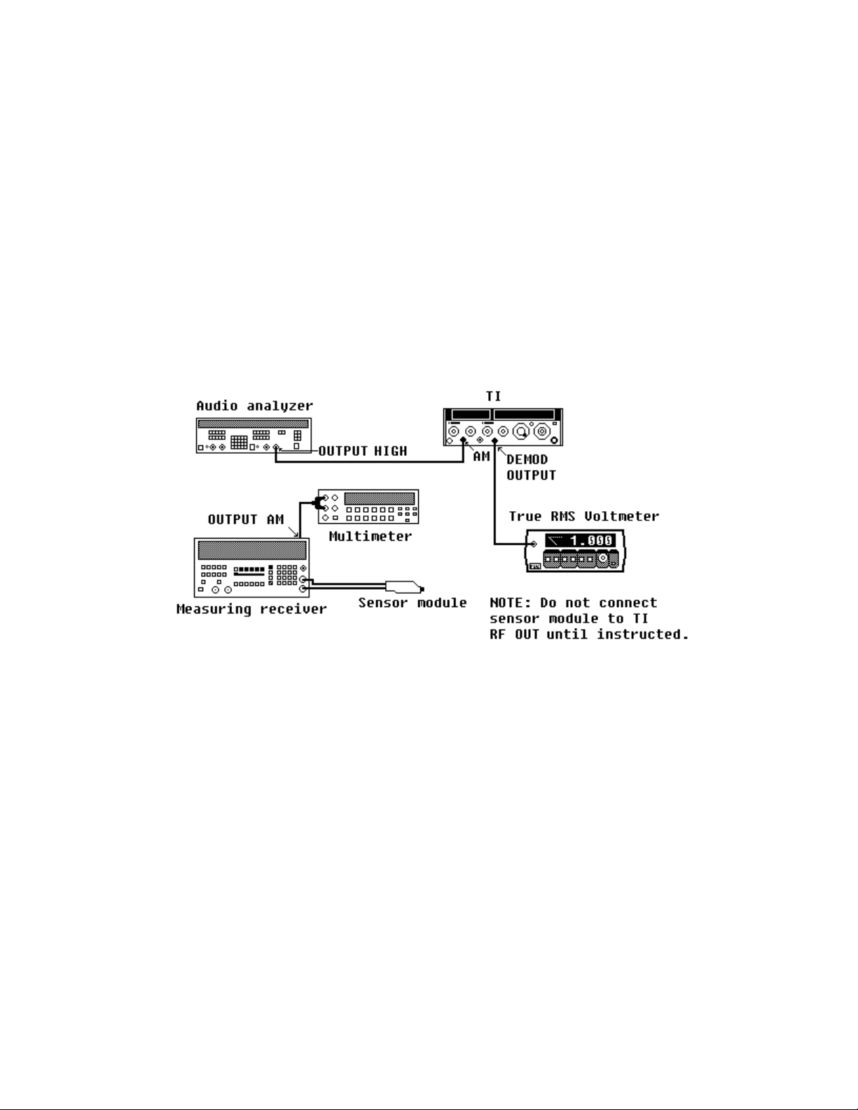
(14) Reduce all outputs to minimum and reconnect equipment as shown in figure 6,
leaving TI RF OUTPUT disconnected.
Figure 6. Demodulated output accuracy - test setup.
(15) Press measuring receiver AUTOMATIC OPERATION and MHz (INPUT
FREQ ) keys.
(16) Record multimeter dc indication as V
off
.
(17) Connect TI RF OUTPUT to measuring receiver sensor module.
(18) Note position of switch A26A8S1 (fig. 2) and set to AC position. If necessary,
turn RF OUTPUT ON.
(19) Adjust audio analyzer controls for a 1 V, 120 Hz output signal.
(20) Adjust AM control for a true RMS voltmeter indication of 1.000 V ac (if necessary
use audio analyzer up/down arrows to fine adjust). Press 6.2 and SPCL keys on measuring
receiver.
33
Page 34
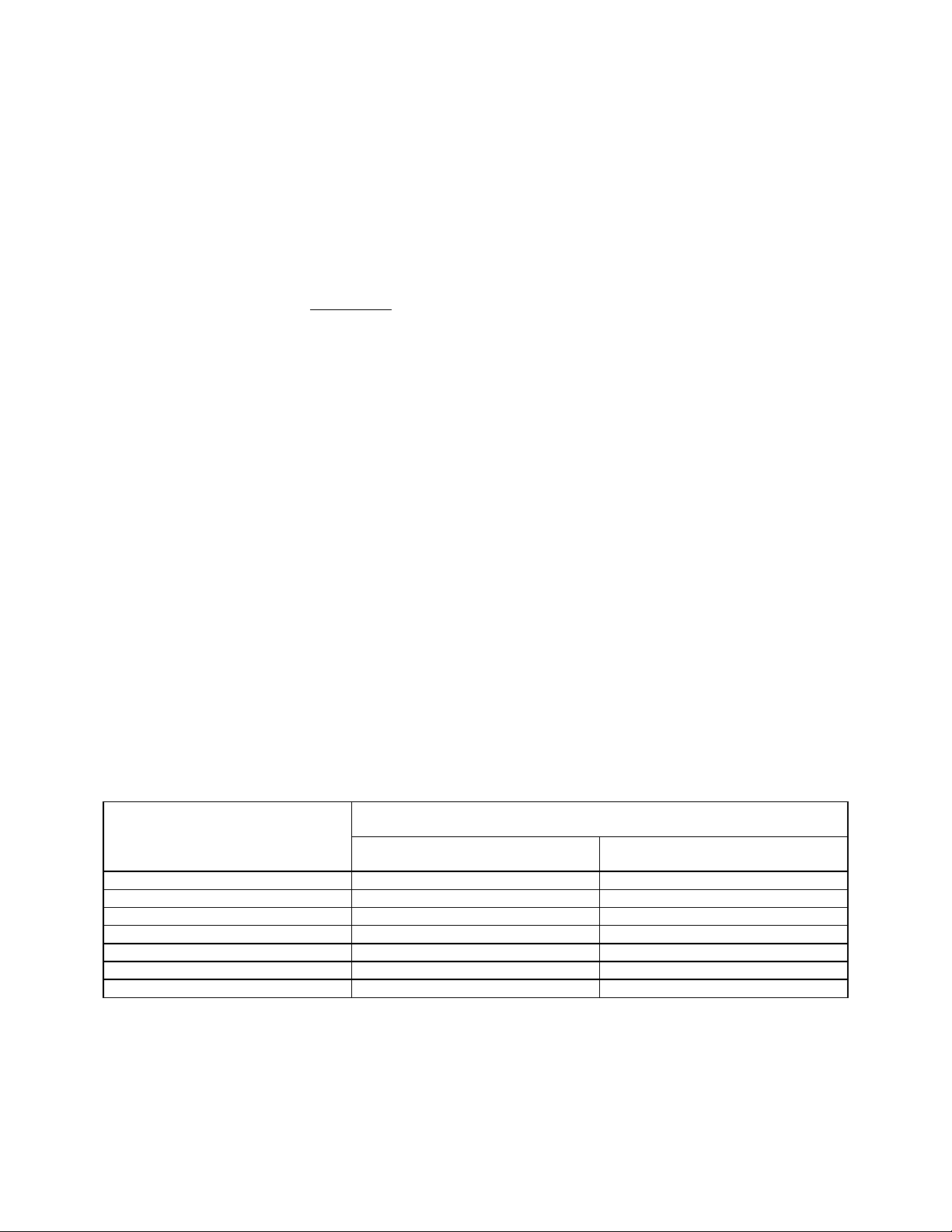
TB 9-4931-488-35
(21) Record multimeter dc indication as V dc.
(22) Set multimeter to measure ac volts and note V ac indication. Multiply this
indication by 1.414 and record as V pk.
(23) Compute the TI % of amplitude modulation (AM), using the following formula.
The computed result will be between min and max limits listed in table 25; if not perform b
below.
% AM = Absolute value of Vpk x 100
(Vdc) - (V
Where: V
V
V
= value recorded in (16) above
off
= value recorded in (21) above
dc
= value recorded in (22) above
pk
)
off
NOTE
If an out-of-tolerance condition is noted in (24) through (27)
below, disconnect input to measuring receiver and insure V
off
value recorded in (16) above has not changed before performing
b below
(24) Repeat technique of (20) through (23) above for multimeter indications listed in
table 25. Computed results will be as specified; if not, perform b below.
(25) Adjust AM control fully ccw. Set switch A26A8S1 (fig. 2) to DC position. Repeat
technique of (20) through (24) above for multimeter indications listed in table 26.
Computed results will be as specified; if not, perform b below.
(26) Adjust AM control fully ccw. Set RANGE MHz switch to 512-256 and adjust
FREQUENCY TUNE control for a FREQUENCY MHz display indication of 333 MHz.
(27) Repeat technique of (15) through (25) above.
(28) Reduce all outputs to minimum.
Table 25. Demodulated Output Accuracy (A26A8Sl Set to AC)
True RMS voltmeter Computed results
(%)
Indications
(V Ac)
1.000 19.6 20.4
1.500 29.4 30.6
2.000 39.2 40.8
2.500 49.0 51.0
3.000 58.8 61.2
3.500 68.6 71.4
4.000 78.4 81.6
Min Max
34
Page 35
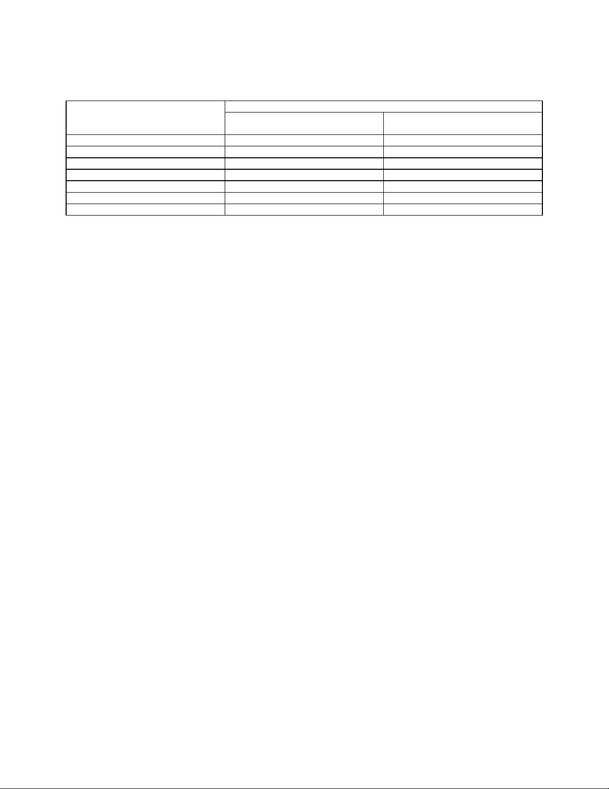
TB 9-4931-488-35
Table 26. Demodulated Output Accuracy (A26A8S1 set to DC)
True RMS voltmeter Computed results (%)
indications
(V Ac)
0.200 19.6 20.4
0.300 29.4 30.6
0.400 39.2 40.8
0.500 49.0 51.0
0.600 58.8 61.2
0.700 68.6 71.4
0.800 78.4 81.6
Min
Max
b. Adjustments
NOTE
Disconnect all equipment before proceeding.
(1) Position controls as listed in (a) through (i) below.
(a) LEVEL VOLTS pushbutton pressed.
(b) AM switch to OFF.
(c) RANGE MHz switch to 256-128.
(d) FREQUENCY TUNE control for a FREQUENCY MHz display indication of
190 MHz.
(e) AM control to midrange.
(f) OUTPUT LEVEL 10 dB switch to 0 dBm.
(g) OUTPUT LEVEL 1 dB switch to 0 dB.
(h) OUTPUT LEVEL vernier control to CAL.
(i) RF OFF/ON switch to OFF.
(2) Connect A26A8TP2 (fig. 2) to chassis ground. Set A26A8S1 switch (fig. 2) to AC.
(3) Connect multimeter to A26A8TP1 (fig. 2) and chassis ground. Adjust A26A8R3
(fig. 2) for a 0.000 ±0.001 V dc multimeter indication (R).
(4) Set A26A8S1 switch (fig. 2) to DC. Disconnect multimeter from A26A8TP1 (fig.
2) and connect to A26A8TP3 (fig. 2). Adjust A26A8Rl5 (fig. 2) for a 0.000 ±0.001 V dc
multimeter indication (R).
(5) Disconnect ground from A26A8TP2 (fig. 2). Disconnect multimeter from
A26A8TP3 (fig. 2). Set multimeter to measure AC voltage and connect to AM IN A26A2TP1
and GRD (fig. 2).
(6) Connect audio analyzer OUTPUT HI to TI AM input. Adjust audio analyzer
controls for a 100 Hz output signal and adjust amplitude controls for a 0..52-V ac output
level.
(7) Set RF OFF/ON switch to ON and AM switch to DC. Adjust AM control for a
0.3536 ±0.0005 V ac multimeter indication.
35
Page 36

TB 9-4931-488-35
(8) Disconnect multimeter from A26A2TP1 (fig. 2). Set multimeter to measure dc
voltage and connect to AM OUT A26A2TP3 (fig. 2). Record multimeter indication (should
be 2.0 ±0.1 V dc).
(9) Multiply value recorded in (8) above by 0.3536. Set multimeter to measure ac
voltage. Adjust % AM A26A2R19 (fig. 2) until multimeter indicates within ±0.001 V ac of
value computed above (R).
(10) Disconnect multimeter from A26A2TP3 (fig. 2). Set multimeter to measure dc
voltage and connect to DEMOD OUT. Adjust A26A8R10 (fig. 2) for a 1.414 ±0.001-V dc
multimeter indication (R).
(11) Set A26A8S1 switch (fig. 2) to AC. Adjust A26A8R6 (fig. 2) for a 0.000 ±0.001-V
dc multimeter indication (R).
(12) Set multimeter to measure ac voltage. Adjust A26A8R8 (fig. 2) for a 2.500 ±0.001
V ac multimeter indication (R).
(13) Return A26A8S1 switch (fig. 2) to position noted in a (18) above, provided a (18)
was performed.
(14) Connect equipment as shown in figure 6 except do not connect the true RMS
voltmeter.
(15) Set measuring receiver to measure AM with peak + detector. Set high-pass filter
to 50 Hz and low-pass filter to 15 kHz.
(16) Press measuring receiver AUTOMATIC OPERATION and FREQ MHz keys.
(17) Record multimeter dc indication as V
off.
(18) Adjust audio analyzer controls for a 120-Hz, 600 Ω, 0.459 V output.
(19) Connect the measuring receiver sensor module to the TI RF OUT.
(20) Press AM X10% pushbutton and adjust AM vernier control fully cw.
(21) Adjust the audio analyzer output for a TI meter indication of 50%. Press 6.2 and
SPCL keys on measuring receiver.
(22) Record multimeter dc indication as Vdc
.
(23) Calculate the AC component (Vac) using the formula. Round the calculated
value to 3 digits and record as Vac.
Vac = absolute value of (.5*( Vdc - V
)/1.414)
off
(24) Set multimeter to measure ac voltage and adjust the audio analyzer output for a
multimeter indication as close as possible to the Vac value recorded in (23) above.
(25) Disconnect the multimeter from measuring receiver and connect it to TI
DEMOD OUT.
(26) Adjust A26A8R8 (fig. 2) for a multimeter indication of 2.5 ±0.005 Vrms.
(27) Disconnect the multimeter from the TI and connect to measuring receiver rear
panel OUTPUT AM.
36
Page 37

TB 9-4931-488-35
(28) Set multimeter to measure dc voltage. Record multimeter dc indication as Vdc1.
(29) Set multimeter to measure ac voltage. Record multimeter dc indication as Vac1.
(30) Calculate the modulation output component (Modout) using the formula.
Modout = absolute value of (Vac1*1.414)/(Vdc1-Voff))*100
(31) Set multimeter to measure dc voltage.
(32) If Modout is not between 49.9 and 50.1 then record the multimeter indication as
dcv and repeat (23) through (31) above.
(33) Set A26A8S1 switch (fig. 2) to DC.
(34) Set multimeter to measure dc voltage, adjust the audio analyzer output for a TI
meter indication of 50%.
(35) Repeat technique of (22) through (25) above.
(36) Adjust A26A8R10 (fig. 2) for a multimeter indication of 0.50000 ±0.00005 Vrms.
(37) Repeat technique of (27) through (32) above.
(38) Disconnect multimeter from the measuring receiver and connect to the TI
DEMOD OUTPUT.
(39) Adjust A26A8R15 (fig. 2) for a multimeter indication of 1.414 ±0.001 Vdc.
(40) Set AM and RF OFF/ON switch to OFF.
17. AM Flatness (Option 004 Only)
a. Performance Check
(1) Press Instrument Preset on measuring receiver, then set to measure AM.
(2) Position TI controls as listed in (a) through (e) below.
(a) AM switch to OFF.
(b) AM control fully ccw.
(c) RANGE MHz switch to 128-64.
(d) FREQUENCY TUNE control for a 113 MHz indication on FREQUENCY
MHz display.
(e) OUTPUT LEVEL switches for a 0-dBm output.
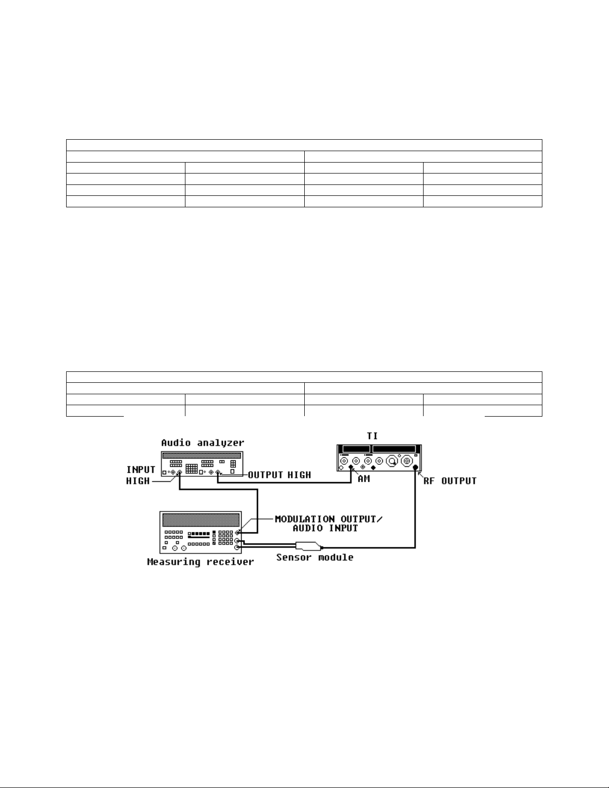
(3) Connect equipment as shown in figure 7.
(4) Adjust audio analyzer amplitude and frequency controls for 1.0 V rms at 90 Hz
level.
(5) Set AM switch to DC and adjust AM control for TI meter indication of 50% AM.
(6) Set audio analyzer to measure AC level in dB mode, then press the audio
analyzer RATIO key.
(7) Set the audio analyzer output for a 150 Hz output then set to measure level.
37
Page 38
TB 9-4931-488-35
(8) The audio analyzer will indicate between limits listed in table 27.
(9) Repeat technique of (7) and (8) above for remaining settings in table 27.
Table 27. AM Flatness 113 MHz Option 004 Only.
Audio analyzer
Source Level limits
Level (V) Frequency (Hz) Min Max
1 150 -.1 +.1
1
1
1
Repeat (3) through (5) above at 9 kHz source frequency before performing this step.
1 11 k -.1 +.1
10 k -.1 +.1
(10) Set audio analyzer RATIO off and source to 90 Hz.
(11) Adjust AM control fully ccw. Set RANGE MHz switch to 512-256 and adjust
FREQUENCY TUNE control for FREQUENCY MHz display indication of 332 MHz.
(12) Adjust AM control for TI meter indication of 50% AM.
(13) Set audio analyzer to measure AC level in dB mode, then press the audio
analyzer RATIO key.
(14) Set the audio analyzer output for a 150 Hz output then set to measure level.
(15) The audio analyzer will indicate between limits listed in table 28.
Table 28. AM Flatness 332 MHz Option 004 Only.
Audio analyzer
Source Level limits
Level (V) Frequency (Hz) Min Max
1 150 -.1 +.1
Figure 7. AM flatness - test setup.
b. Adjustments. No adjustments can be made.
38
Page 39
TB 9-4931-488-35
18. FM Sensitivity, Accuracy, and Distortion
a. Performance Check
(1) Position controls as listed in (a) through (e) below:
(a) FM k/MHz pushbutton pressed.
(b) PEAK DEVIATION switch to 320 kHz.
(c) FM control fully cw.
(d) RANGE MHz switch to 128-64.
(e) FM switch to AC.
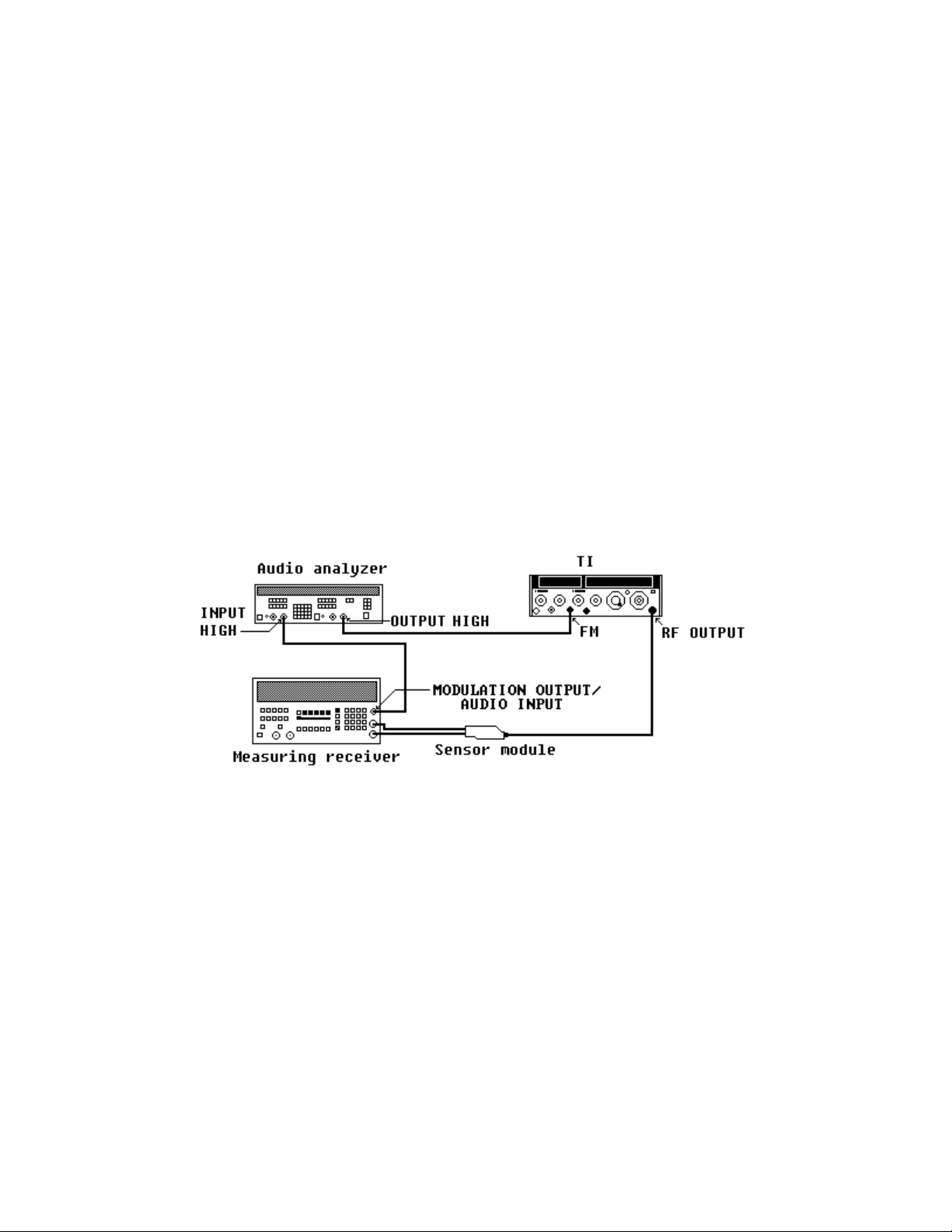
(2) Connect equipment as shown in figure 8.
(3) Set measuring receiver to measure FM. Set the high-pass filter to 50 Hz and
low-pass filter to 15 kHz and use peak + detector.
(4) Set audio analyzer for a 1-kHz 1.414-V ac output level.
(5) Adjust FREQUENCY TUNE control for a FREQUENCY MHz display
indication of 64 MHz.
(6) Set PEAK DEVIATION switch to positions listed in table 29. The measuring
receiver will indicate as specified; if not, perform b below.
Figure 8. FM - test setup.
(7) Repeat (5) and (6) above remaining settings in table 29.
39
Page 40
TB 9-4931-488-35
Test Instrument
FREQUENCY MHz
display
64 320 301 339
64 160 150 170
64 80 75.2 84.8
64 40 37.6 42.4
64 20 18.8 21.2
64 10 9.40 10.6
64 5 4.70 5.30
90 320 301 339
90 160 150 170
90 80 75.2 84.8
90 40 37.6 42.4
90 20 18.8 21.2
90 10 9.40 10.6
90 5 4.70 5.30
128 320 301 339
128 160 150 170
128 80 75.2 84.8
128 40 37.6 42.4
128 20 18.8 21.2
128 10 9.40 10.6
128 5 4.70 5.30
Table 29. FM Sensitivity
PEAK DEVIATION
switch settings
Measuring receiver
Min
indications
(kHz)
Max
(8) Set RANGE MHz switch to 512-256 and adjust FREQUENCY TUNE for TI
display indication of 512 MHz.
(9) Set measuring receiver for FM measurement in the automatic operation mode
with peak + detector.
(10) Set PEAK DEVIATION switch to settings and adjust audio analyzer output
level controls for TI meter indications listed in table 30. If measuring receiver does not
indicate as specified, perform b below.
Table 30. FM Accuracy
Test nstrument
PEAK DEVIATION
switch settings
Min Max
5 5 4.58 5.43
10 10 9.15 10.8
20 20 18.1 21.9
40 40 36.5 43.5
80 80 72.9 87.1
160 160 144 176
320 320 293 347
1
Use scale reference that is lit up under SCALE to left of TI meter.
40
Test instrument
meter
indications
1
Measuring receiver indications
(KHz)
Page 41
TB 9-4931-488-35
(11) Set RANGE MHz switch to 64-32 and adjust FREQUENCY TUNE for
FREQUENCY MHz display indication of 32 MHz.
(12) Set PEAK DEVIATION switch to 320 kHz and adjust FM control fully cw.
(13) Adjust audio analyzer output level controls for 320 kHz measuring receiver
indication. If distortion is not ≤ 3 %, perform b below.
(14) Repeat technique of (11) through (13) above, using settings listed in table 31.
The distortion analyzer will indicate as specified; if not, perform b below.
Table 31. FM Distortion
Test instrument
FREQUENCY TUNE
and FINE TUNE control
settings
(MHz)
32 320 320 3
32 40 40 1
45 40 40 1
45 320 320 3
64 320 320 3
64 40 40 1
PEAK DEVIATION
switch settings
(kHz)
Measuring receiver
indications
(kHz)
Audio analyzer
distortion
indication
(<%)
(15) Set RF OFF/ON switch to OFF.
b. Adjustments
NOTE
Disconnect all equipment before proceeding.
(1) Position controls as listed in (a) through (h) below:
(a) COUNTER MODE pushbuttons as listed in 1. through 3. below:
1
2.
3
. EXPAND X10 and X100 released.
LOCK ON released.
. INT pressed.
(b) FM k/MHz pushbutton pressed.
(c) PEAK DEVIATION switch to 2.56 MHz.
(d) FM control fully cw.
(e) RANGE MHz switch to 512-256.
(f) FREQUENCY TUNE control for FREQUENCY MHz display indication of
300 MHz.
(g) FM switch to DC.
(h) RF OFF/ON switch to ON.
(2) Connect multimeter INPUT HI to BUFFER OUTPUT A5TP6 (fig. 3) and
INPUT LO chassis ground. Adjust A5R23 (fig. 3) for a 0.000 ±0.0005V dc multimeter
indication (R).
41
Page 42

TB 9-4931-488-35
(3) Disconnect multimeter INPUT HI from A5TP6 (fig. 3) and connect to OUTPUT
A5TP2 (fig. 3). Adjust OFFSET A5R8 (fig. 3) for a 0.000 ±0.001-V dc multimeter indication
(R).
(4) Set FM switch to CAL. Disconnect multimeter INPUT HI from A5TP2 (fig. 3)
and connect INPUT HI to BUFFER IN A5TP5 (fig. 3). Adjust FM CAL A13R3 (fig. 3) for a
1.000 ±0.001-V dc multimeter indication (R).
(5) Disconnect multimeter INPUT HI from A5TP5 (fig. 3) and connect to
VARACTOR ANODE A7TP2 (fig. 3). Adjust A7R19 (fig. 3) for a -14.70 ±0.01-V dc
multimeter indication (R).
(6) Connect equipment as shown in figure 8.
(7) Position controls as listed in (a) through (j) below.
NOTE
Some of these TI control settings are repeated from
performance check because of their importance to adjustment
procedure.
(a) LEVEL VOLTS pushbutton pressed.
(b) AM switch to OFF.
(c) FM switch to INT.
(d) FM control fully ccw.
(e) MODULATION FREQUENCY RANGE switch to FIXED FREQ 1 kHz.
(f) PEAK DEVIATION switch to 320 kHz.
(g) RANGE MHz switch to 64-32.
(h) FREQUENCY TUNE control for FREQUENCY MHz display indication of
50 MHz.
(i) OUTPUT LEVEL switch to +10 dBm (10 dB switch to +10 and 1 dB switch
to 0 for option 004).
(j) OUTPUT LEVEL vernier control(s) fully cw.
(8) Set measuring receiver to measure peak FM with a 50 Hz high-pass and 15 kHz
low-pass filter. Set tuning to track mode (key in 4.1 SPCL).
(9) Adjust FM control for a 320 kHz measuring receiver indication. Set audio
analyzer to measure distortion at 1 kHz.
(10) Adjust POS SHAPE A7R12 and NEG SHAPE A7R41 (fig. 3) for minimum
indication (<3 %) on audio analyzer (R).
(11) Adjust FREQUENCY TUNE control slowly from 32 to 64 MHz while observing
audio analyzer. If audio analyzer does not indicate ≤3 %, repeat (9) and (10) above while
adjusting for best intolerance condition across the band.
(12) Position controls as listed in (a) through (d) below.
(a) FM switch to AC.
(b) PEAK DEVIATION switch to 80 kHz
42
Page 43
TB 9-4931-488-35
(c) FM control fully cw.
(d) FREQUENCY TUNE control for FREQUENCY MHz display indication of
50 MHz.
(13) Set audio analyzer for a 1 kHz 1.414 V ac output level.
(14) Repeat (8) above.
(15) Adjust MID R3 (fig. 3) for a 80.0 ±0.1 kHz measuring receiver indication (R).
(16) Adjust FREQUENCY TUNE control for FREQUENCY MHz display indication
of 32 MHz. Adjust LOW R2 (fig. 3) for a 80.0 ±0.1-kHz measuring receiver indication (R).
(17) Adjust FREQUENCY TUNE control for FREQUENCY MHz display indication
of 64 MHz. Adjust HIGH R4 (fig. 3) for a 80.0 ±0.1 kHz measuring receiver indication (R).
(18) Adjust FREQUENCY TUNE control for FREQUENCY MHz display indication
of 50 MHz and repeat (15) through (17) above until measuring receiver indication is 80.0
±0.2 kHz at 32, 50, and 64 MHz.
(19) Set FM and RF OFF/ON switches to OFF and repeat a above.
19. Power Supply
a. Performance Check
(1) Remove top cover from TI.
(2) Check to see that the five LED's on supply boards (fig. 2) are on.
(3) Connect multimeter to test points listed in table 32 and chassis ground. If
multimeter does not indicate within limits specified in table 32, perform adjustments listed.
Table 32. Power Supply Check
Test
instrument
test point
locations
(fig. 2)
A18TP31 -5.10 -5.30 A18R1
A20TP10 +5.10 +5.30 A20R16 +5.2
A22TP4 +19.90 +20.10 A22R7 +20
A22TP9 -19.90 -20.10 A22R19 -20
A20TP4 +44.50 +44.70 A20R8 +44.6
1
For some models, this may be TP5.
2
For some models, this may be A18R2.
Dc voltage limits Adjustments
locations
(fig. 2) (R)
Min Max (V Dc)
2
Multimeter
indications
-5.2
20. Final Procedure
a. Deenergize and disconnect all equipment.
b. Annotate and affix DA label/form in accordance with TB 750-25.
43
Page 44

By Order of the Secretary of the Army:
Official:
JOHN M. KEANE
General, United States Army
Acting Chief of Staff
JOEL B. HUDSON
Administrative Assistant to the
Secretary of the Army
0318209
DISTRIBUTION:
To be distributed in accordance with IDN 342064, requirements for calibration procedure
TB 9-4931-488-35.
Page 45

Instructions for Submitting an Electronic 2028
The following format must be used if submitting an electronic 2028. The subject line must
be exactly the same and all fields must be included; however, only the following fields are
mandatory: 1, 3, 4, 5, 6, 7, 8, 9, 10, 13, 15, 16, 17, and 27.
Subject: DA Form 2028
1. From: Joe Smith
2. Unit: home
3. Address: 4300 Park
4. City: Hometown
5. St: MO
6. Zip: 77777
7. Date Sent: 19-OCT –93
8. Pub no: 55-2840-229-23
9. Pub Title: TM
10. Publication Date: 04-JUL-85
11. Change Number: 7
12. Submitter Rank: MSG
13. Submitter FName: Joe
14. Submitter MName: T
15. Submitter LName: Smith
16. Submitter Phone: 123-123-1234
17. Problem: 1
18. Page: 2
19. Paragraph: 3
20. Line: 4
21. NSN: 5
22. Reference: 6
23. Figure: 7
24. Table: 8
25. Item: 9
26. Total: 123
27. Text
This is the text for the problem below line 27.
Page 46

PIN: 063108-000
 Loading...