


Agilent 8509B
Lightwave
Polarization Analyzer
Optical polarization
measurements of signal
and components
1200 nm to 1600 nm
Product Overview
2
The Agilent 8509B
Lightwave Polarization Analyzer
The Agilent 8509B lightwave
polarization analyzer offers highspeed, calibra-ted polarization
measurements of both optical
signals and components. These
capabilities are provided by
innovations in hardware, software,
and applications of Jones matrix
and Stokes vector mathematics.
The Agilent 8509B analyzer
facilitates a greater
understanding of the polarization
properties of lightwave signals and
materials in helping to develop
higher performance light-wave
components and systems, as well
as more effective test and
manufacturing processes. These
developments involve many types of
polarization-sensitive devices which
are used in communications, sensors,
optical computing and material
analysis; devices such as single-mode
fibers, polarization-maintaining
fibers, isolators, optical switches,
lasers, beamsplitters, modulators,
interferometers, retardation plates
and, of course, polarizers and
polarization adjusters.
Polarization characteristics affect
all lightwave transmissions. The
polarization of a lightwave signal
is defined by its E-field components.
As a signal propagates, interaction
with optical components and other
lightwave signals (in interferometric
applications) modifies the magnitude
and phase of the signal’s E-field
components. Polarization-dependent
loss, gain or even signal distortion
may occur depending on the
application.
Polarization mode dispersion is a
key hurdle limiting the transmission
of signals at 10 Gbit/s and above.
The Agilent 8509B lightwave
polarization analyzer in conjunction
with the Agilent 8168 series
tunable laser source or the Agilent
83432A temperature tuned DFB
laser can be used to measure PMD
of fiber and compo-nents down to
1 fs resolution.
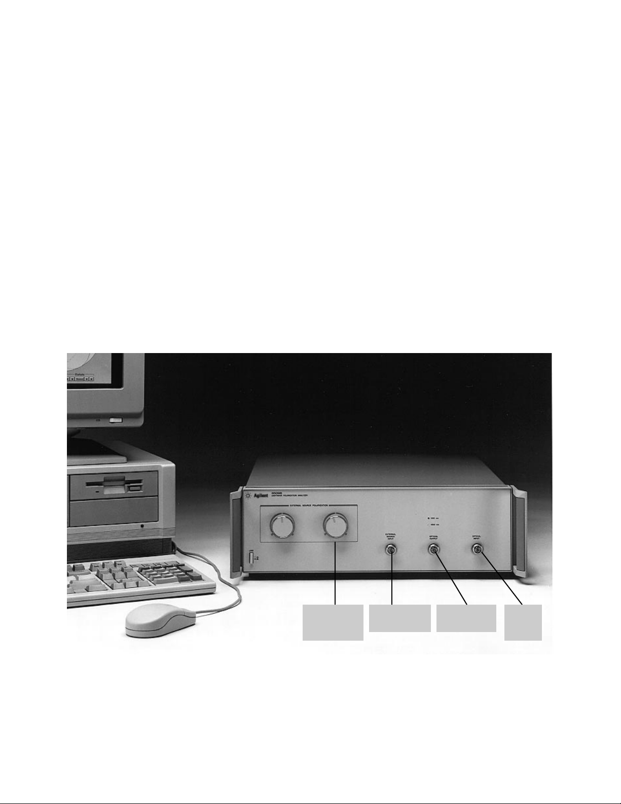
Optical Source
Output
External Source
Input
External Source
Polarization
Controller
Optical
Receiver
Input

3
In order to maintain a competitive
edge, R&D and manufacturing
operations need fast, accurate,
easy-to-understand measurement
data. This reduces the time and
expense of bringing a product to
market. The Agilent 8509B can
help.
Test times are reduced by the
system’s versatile and powerful
combination of hardware and
software technology. A four-diode
detection scheme delivers real-time
polarization information by constantly
monitoring all signal polarization
states from 1200 nm to 1600 nm.
Test setup is easier with the choice
of using external lightwave sources
or using the Agilent 8509B internal
1300 nm and 1550 nm Fabry-Perot
lasers. Polarization control is available using the automatic, threestate polarization generator.
Polarization mode dispersion and
polarization-dependent loss measurements are quick and simple using
the Agilent 8509B automatic
measure-ment procedures.
Measurement accuracy is provided
by the system’s accuracy enhancement techniques. Agilent 8509B
polarization reference frames enable
accurate testing in bulk optics and
fiber cables by removing unwanted
fiber cable effects. The Agilent
Accurate, easy-to-understand
data in less time
HP 8509B
Polarization
Adjuster
1500 nm 1300 nm
Internal Lasers
Three-State
Polarization
Generator
External
Source
Input
Optical
Output
Test Device
Test Signal
Optical
Input
Photodiode Detectors
Polarization Filters
Four-Way Beam Splitter
8509B wavelength calibration
capability automatically optimizes
the system receiver for the best
performance based on the
polarization and wavelength of a
test signal.
Polarization is easier to understand
when data is presented in the
appropriate display formats. When
tuning the polarization of a lightwave signal, for example, the
Poincare sphere is the best format
because the tuning process is
visually guided by a moving
polarization trace on the sphere.
For mathematical specifications of
signal polarization, the Stokes
parameter format is best because it
is used in polarization calculations.
Whichever format is needed, the
Agilent 8509B can meet the need
with simultaneous data displays in
a variety of different formats.
In the lab and on the production
line, scientists, engineers and
technicians depend on the speed,
accuracy and convenience of the
Agilent 8509B to accurately
measure and predict the
polarization of signals and the
polarization trans-mission
properties of components.
Agilent 8509B measurement capability
and data format summary
• Polarization Ellipse
• Poincare Sphere
• Degree of Polarization
• Stokes Parameters
• Average Power
• Jones Matrix
• Polarization Mode Dispersion
• Polarization-Dependent Loss
• Polarization-Maintaining-Fiber Launch Conditions
Figure 1.
Agilent 8509B block diagram
Agilent 8509B

4
Measure optical
signal polarization
Increase accuracy and make polarization easier to understand
with polarization reference frame
procedures and multiple, simultaneous display formats.
Figure 2. Signal polarization
measurement setup
State of Polarization
In fiber cables and bulk-optics, the
Agilent 8509B delivers high-speed
signal polarization analysis by performing over 1000 polarization
measurements per second. Data
averaging can be applied before it
is displayed as average power, polarization ellipse, Stokes parameters
and points on a Poincare sphere.
Three data markers provide Stokes
parameter analysis and relative
angle comparisons between specific
data points on the Poincare sphere.
Polarization
Reference Frame
Polarization reference frames are
especially valuable for optical sensor
and bulk-optic sub-system applications where location-specific signal
polarization information is needed.
In these cases the test system must
remove its own responses from the
test data to minimize measurement
uncertainty. Improved accuracy
makes measurement results easier
to interpret, document and
reproduce.
The Agilent 8509B quickly defines
a polarization reference frame at a
specific location using three polarization standards. The absolute
polarization accuracy of the reference
frame depends largely on the
standards used.
Jones Matrix
A 2 X 2 complex Jones matrix,
measured by the Agilent 8509B,
mathematically describes how an
individual optical component will
affect the magnitude and polarization of a transmitted signal. The
Jones matrices of many components
can be mathematically combined.
A combined Jones matrix can be
used to calculate the total polarization effect that would be measured
by actually connecting the components. This can be helpful when
Figure 3. Angular relationships between different
signal polarization states can be analyzed using
Agilent 8509B Poincare sphere data markers.
attempting to select a
combination of components
that will produce a certain
polarization effect. Jonesmatrix analysis is also used
to calculate polarization mode
dispersion and polarizationdependent loss of systems
and components.
Figure 4.
The Agilent 8509B
displays the Jones
matrix of two-port
optical components
and systems.
Agilent 8509B
External
Source
Input
Optical
Input
Optical
Output
Signal Under Test
Lightwave
Source

5
Measure polarization transmission properties
of components
Reduce design and manufacturing
uncertainties by measuring the
effects of the polarizationdependent transmission properties
of optical components and systems.
Figure 6.
Polarization mode
dispersion data for
a 40 km length of
SMF cable is shown
on a graph and on
the Agilent 8509B
Poincare sphere.
Polarization Mode
Dispersion
Polarization mode dispersion (PMD)
is an intramodal distortion mechanism (like chromatic dispersion)
that causes optical devices, such as
single-mode fibers, optical switches
and optical isolators, to distort
transmitted signals. Negative
effects appear as random signal
fading, increased composite second
order distortion and increased digital error rates. Designers and application engineers can take action to
reduce PMD and specify maximum
tolerances for specific applications
when PMD is quantified.
Fast, accurate and repeatable, the
Agilent 8509B’s automatic Jonesmatrix eigenanalysis technique
measures PMD with typically
better than 60 fs accuracy. Jones
matrices of a component are
measured at consec-utive
wavelength steps. Sets of Jones
matrices are then analyzed to
calculate PMD with 1 fs resolution.
A tunable lightwave source, like
the Agilent 8168D tunable laser or
Agilent 83424A temperature-tuned
DFB laser, is needed for this
measurement and connects with
the Agilent 8509B EXTERNAL
SOURCE INPUT.
Figure 5.
Polarization mode
dispersion measurement setup using the
Agilent 8509B and
Agilent 8168 or
Agilent 83424
lightwave sources.

6
Measure polarization transmission properties of
components
Polarization-Dependent Loss
Figure 7. Polarization-dependent
loss measurement setup.
Figure 8. Polarization-dependent loss data
is displayed numerically and graphically.
Figure 9. Typical display of polarization
maintaining fiber launch alignment process.
Data Output
and Remote Operation
Measurement displays and
numerical data are directly output
to paper or transparency using an
external printer or plotter. Graphic
enhancements and additional
mathematical manipulation are
possible on an external computer.
This can be done via GPIB data
extraction or by using a disc.
External controllers remotely
control the Agilent 8509A/B system
using GPIB.
Polarization-dependent loss (PDL)
is a power-loss mechanism which
varies as the polarization of the
input signal changes. When components are connected in a system,
their individual polarizationdependent losses combine to affect
system performance. Chances of
performance degradation are minimized by considering polarizationdependent loss in worst-case power
calculations and in bit error-rate
estimations.
In seconds, the Agilent 8509B uses
an automated Jones-matrix
technique to measure the
maximum, minimum and delta
optical insertion loss of a
component for all possible input
states of polarization. PDL markers
on the Poincare sphere (Figure 8.0)
show the relative location of the
output states of polarization where
the maximum and minimum
losses occur.
Polarization-Maintaining
Fiber Launch
Whenever a single-mode fiber is
moved, it changes the polarization
of the transmitted lightwave.
A polarization-maintaining fiber,
however, can deliver a linearly
polarized lightwave signal regardless of its position. Maximum
performance of 30 dB to 40 dB
extinction ratios are only possible
when linearly polarized light is
correctly launched onto one of the
fiber’s polarization axis. Fiber
alignments with 40 dB extinction
ratios are easily achieved in seconds
using the system’s Poincare sphere
display technique.
External
Source
Optical
Output
Optical
Input
t
Inpu
Agilent 8509B
DUT

Wavelength Step 1310 nm 1550 nm
0.01 nm 280 ps 400 ps
0.10 nm 28 ps 40 ps
1.0 nm 2.8 ps 4 ps
10.0 nm 0.28 ps 0.4 ps
7
Specifications
for the Agilent 8509B
Lightwave Polarization Analyzer
Maximum Measurable PMD Delay:
λ
Min Typical Max
Average Optical Power Output 1310 nm 200 uW 300 uW 500 uW
1550 nm 150 uW 230 uW 400 uW
Wavelength 1310 nm ±20 nm
1550 nm ±20 nm
Spectral width (RMS) 1310 nm 5 nm
1550 nm 5 nm
Return loss 17 dB
Laser type Fabry-Perot
Agilent 8509B External Source
Input Port Characteristics
Wavelength operating range: 1200 nm to 1580 nm
Internal path insertion loss: 8.5 dB
(EXTERNAL SOURCE INPUT to OPTICAL OUTPUT)
Input power operating range: +16 dBm to –49 dBm
Input average power damage level: +22 dBm
Return loss (based on OPTICAL OUTPUT connection
with return loss of 30 dB or greater): 35 dB
Agilent 8509B Polarization Mode Dispersion
(PMD) Specifications Using Eigenanalysis
Technique
Typical wavelength operating range:
1280 nm to 1340 nm
1470 nm to 1580 nm
Warranted wavelength operating range:
1540 nm to 1560 nm.
Resolution: 1 fs
Polarization Dependence Measurement
Characteristics Using Jones-Matrix
Analysis Technique
Wavelength operating range:
1280 nm to 1340 nm
1470 nm to 1580 nm
Measurement range: <3 dB
Uncertainty: ±0.1 dB
Polarization-Maintaining Fiber Launch
Alignment Characteristics Using Poincare
Sphere Technique
Extinction ratio range: 0 dB to 50 dB
Resolution: 0.01 dB
General Specifications
Compatible fiber: 9/125 um
Dimensions: (H x W x D)
133.4 mm x 425.5 mm x 546.1 mm
5.25 in x 16.75 in x 21.5 in
Weight (without computer and monitor):
Net : 10.5 kg (23 lbs)
Shipping: 16.0 kg (23 lbs)
Power Requirements
(without computer and monitor):
47.5 Hz to 66 Hz
90 V to 132 V or 198 V to 264 V
100 VA
Wavelength Step Uncertainty (±)
0.10 nm 310 fs
1.0 nm 90 fs
10.0 nm 60 fs
Delay Uncertainty:
Specifications describe the instrument’s warranted performance over the 23 ±3°C temperature range, except where noted. All
specifications apply after the instrument’s temperature has stabilized (typically 1 hour after turn-on).
Characteristics provide information about non-warranted instrument performance. These are also denoted as typical.
Receiver Characteristics
Wavelength operating range: 1200 nm to 1600 nm
Input power operating range: +10 dBm to –55 dBm
Input average power damage level: +16 dBm
Average power measurement linearity: ±0.06 dB
Average power measurement uncertainty: ±15%
Degree of polarization measurement:
1200 nm to 1280 nm, ±5.0%
1280 nm to 1340 nm, ±2.0%
1470 nm to 1580 nm, ±2.0%
1580 nm to 1600 nm, ±3.0%
Poincare sphere display:
1200 nm to 1340 nm, ±1.5 degrees
1470 nm to 1600 nm, ±1.5 degrees
Polarization state measurement rate:
>1000 per second
Polarization state display update rate:
>1000 per second
Return loss: –50 dB
Agilent 8509B Internal Source Characteristics

Ordering Information
The Agilent 8509B polarization analyzer consists of two
instrument boxes. The first contains the optical
measurement hardware and the second provides the
computer control.
The user interface runs on Microsoft
®
Windows 95
operating system.
The units are configured for optimum performance.
Reconfiguring the hardware, adding to or tampering
with the installed software can degrade or damage the
instrument.
Table 1. Summary of
Agilent 8509B measurement capabilities.
Polarization- Polarization Polarization
State of Degree of Jones Dependent Mode Maintaining
Polarization Polarization Matrix Loss Dispersion Fiber
Agilent 8509B X X X* X X
Agilent 8509B X X X* X X X
+ tunable
source
*
The Agilent 8509B performs this measurement with external polarizers.
Instrument Configuration:
❑ Agilent 8509B Lightwave Polarization Analyzer
Lightwave Interface Connector Option:
Each Agilent 8509B order must be accompanied by
only one of the following connector options.
❑ Option 011 Diamond connector
❑ Option 012 FC/PC connector
❑ Option 013 DIN 47256
❑ Option 014 ST connectors
❑ Option 015 Biconic connectors
Additional Lightwave Interface Connectors:
❑ Agilent 81000 AI Diamond HMS-10
❑ Agilent 81000 FI FC/PC
❑ Agilent 81000 GI D4
❑ Agilent 81000 KI SC
❑ Agilent 81000 SI DIN 47256
❑ Agilent 81000 VI ST
❑ Agilent 81000 WI Biconic
Microsoft®is a registered trademark of Microsoft Corp.
For more information about Agilent Technologies
test and measurement products, applications,
services, and for a current sales office listing,
visit our web site,
www.agilent.com/comms/lightwave
You can also contact one of the
following centers and ask for a test and
measurement sales representative.
United States:
Agilent Technologies
Test and Measurement Call Center
P.O. Box 4026
Englewood, CO 80155-4026
(tel) 1 800 452 4844
Canada:
Agilent Technologies Canada Inc.
5150 Spectrum Way
Mississauga, Ontario
L4W 5G1
(tel) 1 877 894 4414
Europe:
Agilent Technologies
Test & Measurement
European Marketing Organization
P.O. Box 999
1180 AZ Amstelveen
The Netherlands
(tel) (31 20) 547 2000
Japan:
Agilent Technologies Japan Ltd.
Call Center
9-1, Takakura-Cho, Hachioji-Shi,
Tokyo 192-8510, Japan
(tel) (81) 426 56 7832
(fax) (81) 426 56 7840
Latin America:
Agilent Technologies
Latin American Region Headquarters
5200 Blue Lagoon Drive, Suite #950
Miami, Florida 33126, U.S.A.
(tel) (305) 267 4245
(fax) (305) 267 4286
Australia/New Zealand:
Agilent Technologies Australia Pty Ltd
347 Burwood Highway
Forest Hill, Victoria 3131, Australia
(tel) 1-800 629 485 (Australia)
(fax) (61 3) 9272 0749
(tel) 0 800 738 378 (New Zealand)
(fax) (64 4) 802 6881
Asia Pacific:
Agilent Technologies
24/F, Cityplaza One, 1111 King’s Road,
Taikoo Shing, Hong Kong
(tel) (852) 3197 7777
(fax) (852) 2506 9284
Technical data subject to change
Copyright © 1993
Agilent Technologies
Printed in U.S.A. 4/00
5966-1557E
 Loading...