

Page 1

Reference Guide
Agilent Technologies
85097B VNA Interface Kit
for Electronic Calibration
Manufacturing Part Number: 85091-90010
Printed in USA
Print Date: March 2003
Supersedes: October 2001
© Copyright 2001, 2003 Agilent Technologies, Inc. All rights reserved.
Page 2

Documentation Warranty
THE MATERIAL CONTAINED IN THIS DOCUMENT IS PROVIDED "AS IS," AND IS SUBJECT
TO BEING CHANGED, WITHOUT NOTICE, IN FUTURE EDITIONS. FURTHER, TO THE
MAXIMUM EXTENT PERMITTED BY APPLICABLE LAW, AGILENT DISCLAIMS ALL
WARRANTIES, EITHER EXPRESS OR IMPLIED WITH REGARD TO THIS MANUAL AND ANY
INFORMATION CONTAINED HEREIN, INCLUDING BUT NOT LIMITED TO THE IMPLIED
WARRANTIES OF MERCHANTABILITY AND FITNESS FOR A PARTICULAR PURPOSE.
AGILENT SHALL NOT BE LIABLE FOR ERRORS OR FOR INCIDENTAL OR
CONSEQUENTIAL DAMAGES IN CONNECTION WITH THE FURNISHING, USE, OR
PERFORMANCE OF THIS DOCUMENT OR ANY INFORMATION CONTAINED HEREIN.
SHOULD AGILENT AND THE USER HAVE A SEPARATE WRITTEN AGREEMENT WITH
WARRANTY TERMS COVERING THE MATERIAL IN THIS DOCUMENT THAT CONFLICT
WITH THESE TERMS, THE WARRANTY TERMS IN THE SEPARATE AGREEMENT WILL
CONTROL.
Assistance
Product maintenance agreements and other customer assistance agreements are available
for Agilent products.
For any assistance, contact the nearest Agilent Technologies sales or service office. Refer to
Table 2-1 on page 2-4 for a list of Agilent offices.
ii
Page 3

Contents
1. General Information
VNA Interface Kit Overview . . . . . . . . . . . . . . . . . . . . . . . . . . . . . . . . . . . . . . . . . . . . . . . . . . .1-2
Option 100 . . . . . . . . . . . . . . . . . . . . . . . . . . . . . . . . . . . . . . . . . . . . . . . . . . . . . . . . . . . . . . . .1-2
Compatible Network Analyzers . . . . . . . . . . . . . . . . . . . . . . . . . . . . . . . . . . . . . . . . . . . . . .1-2
VNA Interface Kit Contents . . . . . . . . . . . . . . . . . . . . . . . . . . . . . . . . . . . . . . . . . . . . . . . . . . .1-3
Description of the VNA Interface Kit Contents. . . . . . . . . . . . . . . . . . . . . . . . . . . . . . . . . . .1-4
VNA Interface Kit Setup and Operation. . . . . . . . . . . . . . . . . . . . . . . . . . . . . . . . . . . . . . . . . .1-6
Setup Procedure . . . . . . . . . . . . . . . . . . . . . . . . . . . . . . . . . . . . . . . . . . . . . . . . . . . . . . . . . . .1-6
VNA Interface Kit Characteristics . . . . . . . . . . . . . . . . . . . . . . . . . . . . . . . . . . . . . . . . . . . . . .1-8
Environmental Requirements . . . . . . . . . . . . . . . . . . . . . . . . . . . . . . . . . . . . . . . . . . . . . . . .1-8
Electrical and Mechanical Characteristics . . . . . . . . . . . . . . . . . . . . . . . . . . . . . . . . . . . . . .1-9
Electrostatic Discharge . . . . . . . . . . . . . . . . . . . . . . . . . . . . . . . . . . . . . . . . . . . . . . . . . . . . . .1-10
2. Troubleshooting
General Information. . . . . . . . . . . . . . . . . . . . . . . . . . . . . . . . . . . . . . . . . . . . . . . . . . . . . . . . . .2-2
Returning a VNA Interface Kit to Agilent. . . . . . . . . . . . . . . . . . . . . . . . . . . . . . . . . . . . . . .2-2
Contacting Agilent . . . . . . . . . . . . . . . . . . . . . . . . . . . . . . . . . . . . . . . . . . . . . . . . . . . . . . . . . . .2-4
3. Safety and Regulatory Information
Safety Information . . . . . . . . . . . . . . . . . . . . . . . . . . . . . . . . . . . . . . . . . . . . . . . . . . . . . . . . . . .3-2
Before Applying Power . . . . . . . . . . . . . . . . . . . . . . . . . . . . . . . . . . . . . . . . . . . . . . . . . . . . . .3-2
Instrument Markings . . . . . . . . . . . . . . . . . . . . . . . . . . . . . . . . . . . . . . . . . . . . . . . . . . . . . . .3-3
Safety Earth Ground . . . . . . . . . . . . . . . . . . . . . . . . . . . . . . . . . . . . . . . . . . . . . . . . . . . . . . .3-3
Regulatory Information . . . . . . . . . . . . . . . . . . . . . . . . . . . . . . . . . . . . . . . . . . . . . . . . . . . . . . .3-4
Compliance Notices . . . . . . . . . . . . . . . . . . . . . . . . . . . . . . . . . . . . . . . . . . . . . . . . . . . . . . . .3-4
Contents-i
Page 4

Contents
Contents-ii
Page 5

1 General Information
1-1
Page 6
General Information
VNA Interface Kit Overview
VNA Interface Kit Overview
This manual provides reference information for the Agilent 85097B vector network
analyzer (VNA) interface kit for electronic calibration (ECal).
The VNA interface kit is part of the VNA-based ECal system. The interface kit provides
the hardware to connect and allow data transfer between ECal modules and compatible
network analyzers. See Table 1-1 below.
ECal modules are precision, single-connection devices that provide consistent calibrations
for your network analyzer. ECal uses fully traceable and verifiable electronic standards.
The interface kit does not include the ECal modules, but they can be ordered separately.
For ordering information, see “Contacting Agilent” on page 2-4.
NOTE
For more information about ECal modules, refer to the Electronic Calibration
Module Reference Guide (included with the VNA interface kit).
Option 100
Adds an adapter cable that allows the interface kit to connect to N469x (microwave) ECal
modules. The Option 100 adapter cable can also be ordered separately.
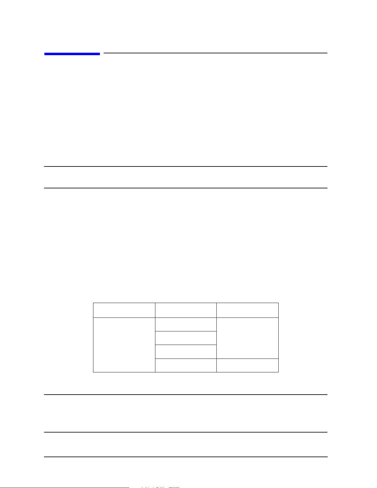
Compatible Network Analyzers
Refer to Table 1-1 for network analyzers and ECal modules compatible with the 85097B
VNA interface kit. The network analyzer must have the appropriate firmware revision
installed to operate with the ECal models shown.
Table 1-1 Supported Network Analyzers and ECal Models
Network Analyzer ECal Model Firmware Revision
8753ES/ET
8719D/ES/ET
8720D/ES/ET
8722D/ES/ET
8509xB/C
8506x
N4431A
N469x
7.68 or higher
a
7.74 or higher
a. Ports A and B only
NOTE
PNA network analyzers are not compatible with the 85097B VNA interface
kit. PNA analyzers allow direct connection of the ECal modules through a
USB connector interface. Refer to the PNA analyzer on-line help system for
more details.
1-2 Chapter 1
Page 7
General Information
VNA Interface Kit Contents
VNA Interface Kit Contents
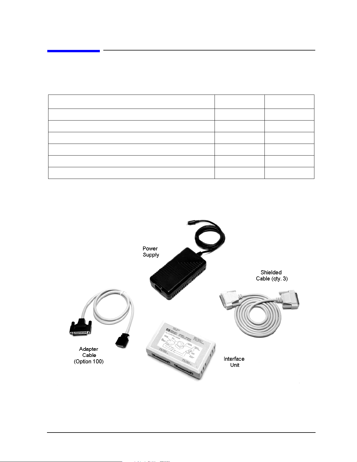
The following table and illustration identify the contents of the 85097B VNA interface kit.
Table 1-2 Contents of the VNA Interface Kit
Description Quantity Part Number
Interface Unit 1 85097-60002
Shielded Cable, DB25 to DB25 3 8120-8710
Adapter Cable, DB25 to AMP Champ (Option 100) 1 8120-1047
Power Supply 1 0950-3331
VNA Interface Kit Reference Guide (this manual) 1 85091-90010
Electronic Calibration Module Reference Guide 1 N4693-90001
Figure 1-1 85097B Kit Contents
Chapter 1 1-3
Page 8

General Information
VNA Interface Kit Contents
Description of the VNA Interface Kit Contents
This section describes the contents of the 85097B VNA interface kit. Refer to Figure 1-3 on
page 1-7 for a system setup diagram using the kit contents.
NOTE
ECal modules are not included in the 85097B VNA interface kit, but are
ordered separately. Refer to the Electronic Calibration Module Reference
Guide (part number N4693-90001) for information on the types and
specifications of ECal modules.
Interface Unit
The interface unit (shown in Figure 1-1) functions as the digital interface and power source
for ECal modules. The interface can connect to one or two ECal modules. Power is
automatically turned off when an ECal module is disconnected.
NOTE
If you are using an 8506xA microwave module with a serial number below
800, a jumper must be installed in the module to make it compatible with the
interface unit. Contact Agilent for information about returning your module
for this modification. Contact information can be found in Table 2-1 on
page 2-4.
Shielded Cables, DB25 to DB25
The shielded cables (shown in Figure 1-1) are male to male RS-232 cables. Three shielded
cables are included in the kit. The cables connect between the VNA and the interface unit
and between the interface unit and one or two ECal modules (except N469x series). The
length of each shielded cable is 1.8 m.
Adapter Cable, DB25 to AMP Champ (Option 100)
The adapter cable (shown in Figure 1-1) is configured with a DB25 to AMP Champ (36-pin)
connector. The adapter cable connects N469x (microwave) ECal modules to the interface
unit. The adapter cable (part no. 8121-1047) can be ordered separately or by adding
Option 100 to the interface kit. The length of the adapter cable is 1.0 m.
CAUTION
Use only the interface cables supplied with this kit. Other cables may cause
the system to fail EMC specifications.
1-4 Chapter 1
Page 9

General Information
VNA Interface Kit Contents
ECal Power Supply Unit
The ECal power supply unit (shown in Figure 1-1) provides 24 Vdc to the interface unit
and power to the ECal modules through the interface unit.
WARNING
CAUTION
WARNING
To prevent electrical shock, disconnect from mains before cleaning.
Use a dry cloth or one slightly dampened with water to clean the
external case parts. Do not attempt to clean internally.
Always use the three-prong ac power cord supplied with this product. Failure
to insure adequate earth grounding by not using this cord may cause product
damage.
The detachable power cord is the instrument disconnecting device.
It disconnects the mains circuits from the mains supply before other
parts of the instrument.
Chapter 1 1-5
Page 10

General Information
VNA Interface Kit Setup and Operation
VNA Interface Kit Setup and Operation
The VNA-based ECal system requires the following components:
• VNA (with appropriate firmware revision) — functions as the ECal system controller
• ECal module — acts as the calibration device for the ECal system
• VNA Interface kit — provides an interface between the ECal module and the VNA
Setup Procedure
Refer to the graphics on the following page for all connections.
CAUTION
Connect Interface Unit to VNA (DB25 to DB25 Cable)
1. Connect one end of the DB25 to DB25 cable to the connector on the interface unit
lableled “DB25 Interface to Parallel Interface on Network Analyzer.”
2. Connect the other end of the DB25 to DB25 cable to the connector on the rear panel of
the VNA lableled “Parallel Port”.
CAUTION
Connect RF Module to Interface Unit (DB25 to DB25 Cable)
1. Connect one end of the DB25 to DB25 cable to the parallel port on the ECal module.
2. Connect the other end of the DB25 to DB25 cable to the connector on the interface unit
labeled “DB25 Interface to ECal Module A” or “DB25 Interface to ECal Module B”.
Connect Microwave Module to Interface Unit (DB25 to AMP Champ Cable)
1. Connect the AMP Champ end of the adapter cable to the parallel port on the ECal
module. Press the tabs on the connector housing to engage the connector.
Exercise the necessary ESD precautions before connecting the devices. Refer
to “Electrostatic Discharge” on page 1-10.
Connecting the interface cable to an unspecified connector on the VNA will
cause damage.
2. Connect the DB25 end of the adapter cable to the connector on the interface unit labeled
“DB25 Interface to ECal Module A” or “DB25 Interface to ECal Module B”.
Connect Interface Unit to Power Supply
1. Connect the interface power supply to the interface unit and then connect to AC power.
2. Allow the ECal module to warm up for 15 minutes (20 minutes for a four-port module)
or until the module indicates READY.
3. ECal module is ready to perform a calibration. Press the
access the calibration types available with ECal.
1-6 Chapter 1
Cal button on the VNA to
Page 11

Figure 1-2 Interface Connection to ECal Module
Figure 1-3 VNA-Based ECal System
General Information
VNA Interface Kit Setup and Operation
• ECal modules can be connected (or disconnected) when the analyzer is turned on or off,
but must remain connected while data transfer is in progress.
• After completing a calibration, the ECal module or modules can remain connected to
the interface unit.
• With the appropriate interface cable, RF or microwave ECal modules can be connected
to position A or B of the interface unit.
Chapter 1 1-7
Page 12

General Information
VNA Interface Kit Characteristics
VNA Interface Kit Characteristics
CAUTION
This product is designed for use in INSTALLATION CATEGORY II and
POLLUTION DEGREE 2, per IEC 1010 and 664 respectively.
Enclosure protection according to IEC 529, IP Code 2 0.
Environmental Requirements
CAUTION
CAUTION
Table 1-3 Environmental Requirements (indoor use only)
When installing the product in a cabinet, the convection in and out of the
product must not be restricted. The ambient temperature (outside the
cabinet) must be less than the maximum operating temperature of the system
by 4 °C for every 100 watts dissipated in the cabinet. If the total power
dissipated in the cabinet is greater than 800 watts, then forced convection
must be used.
Install the instrument according to the enclosure protection provided. This
instrument does not protect against the ingress of water. This instrument
protects against finger access to hazardous parts within the enclosure.
Characteristics Limits
Altitude: up to 3000 meters (10,000 feet)
Temperature: 5 °C to 40 °C (41 °F to 104 °F)
Maximum Relative Humidity:
decreasing linearly to
80% for temperatures up to 31 °C (88 °F)
50% for temperatures to 40 °C (104 °F)
1-8 Chapter 1
Page 13

Electrical and Mechanical Characteristics
General Information
VNA Interface Kit Characteristics
CAUTION
The power supply has auto-ranging line voltage input; be sure the supply
voltage is within the specified range.
Table 1-4 Power Supply Electrical and Mechanical Characteristics
Characteristics Limits
Power Requirements:
Line Voltage
Line Frequency
Pow e r Output : 24 Vdc
Power Dissipation: 192 VA Maximum
Safety: IEC 950
Weights:
Net Weight
Shipping Weight
Dimensions:
Height
100 to 240 Vac
50 to 60 Hz
1 A
0.7 kg (1.5 lbs)
3 kg (6.5 lbs)
41 mm (1.6 in)
Width
Length
158 mm (6.2 in)
97 mm (3.8 in)
Chapter 1 1-9
Page 14

General Information
Electrostatic Discharge
Electrostatic Discharge
Protection against ESD (electrostatic discharge) is essential while connecting, inspecting,
or cleaning connectors attached to a static-sensitive circuit (such as those found in test
sets).
Static electricity can build up on your body and can easily damage sensitive internal
circuit elements when discharged. Static discharges too small to be felt can cause
permanent damage. Devices such as calibration components and devices under test
(DUTs), can also carry an electrostatic charge. To prevent damage to the test set,
components, and devices:
• always wear a grounded wrist strap having a 1 MΩ resistor in series with it when
handling components and devices or when making connections to the test set.
• always use a grounded, conductive table mat while making connections.
• always wear a heel strap when working in an area with a conductive floor. If you are
uncertain about the conductivity of your floor, wear a heel strap.
• always ground yourself before you clean, inspect, or make a connection to a
static-sensitive device or test port. You can, for example, grasp the grounded outer shell
of the test port or cable connector briefly.
• always ground the center conductor of a test cable before making a connection to the
analyzer test port or other static-sensitive device. This can be done as follows:
1. Connect a short (from your calibration kit) to one end of the cable to short the center
conductor to the outer conductor.
2. While wearing a grounded wrist strap, grasp the outer shell of the cable connector.
3. Connect the other end of the cable to the test port.
4. Remove the short from the cable.
Figure 1-4 shows a typical ESD protection setup using a grounded mat and wrist strap. For
parts numbers of ESD protection supplies, refer to “Replaceable Parts” in chapter 6 of the
Electronic Calibration Module Reference Guide.
Figure 1-4 ESD Protection Setup
1-10 Chapter 1
Page 15

2 Troubleshooting
2-1
Page 16

Troubleshooting
General Information
General Information
WARNING
If you suspect a bad calibration, or if your VNA does not pass the performance verification,
follow the steps as shown in Figure 2-1.
NOTE
No operator serviceable parts inside. Refer servicing to qualified
personnel.
This manual contains limited information about VNA system operation. For
information about the VNA’s operation, refer to the VNA’s documentation. If
you need additional information, contact Agilent. See Table 2-1 on page 2-4.
Returning a VNA Interface Kit to Agilent
If any device in the interface kit requires service, contact Agilent for information on where
to send it. See Table 2-1 on page 2-4. When transporting the kit, use original or comparable
packaging. Please include the following information with your returned interface kit.
• your company name and address
• a technical contact person within your company, and the person’s complete telephone
number including country code and area code
• the model number and serial number of the interface kit
• the part number and serial number of each device
• type of service required
• a detailed description of the problem and how the device was being used when the
problem occurred (such as calibration or measurement)
2-2 Chapter 2
Page 17

Figure 2-1 Troubleshooting Flowchart
Troubleshooting
General Information
Chapter 2 2-3
Page 18

Troubleshooting
Contacting Agilent
Contacting Agilent
Using the following table, contact Agilent Technologies by internet, telephone, or fax, to get
assistance with your test and measurement needs.
Table 2-1 Contacting Agilent
Online assistance: www.agilent. com/find/assist
United States
(tel) 1 800 452 4844
New Zealand
(tel) 0 800 738 378
(fax) (+64) 4 495 8950
Malaysia
(tel) 1 800 828 848
(fax) 1 800 801 664
Taiwan
(tel) 0800-047-866
(fax) (886) 2 25456723
Latin America
(tel) (305) 269 7500
(fax) (305) 269 7599
Japan
(tel) (+81) 426 56 7832
(fax) (+81) 426 56 7840
Philippines
(tel) (632) 8426802
(tel) (PLDT subscriber
only):
1 800 16510170
(fax) (632) 8426809
(fax) (PLDT subscriber
only):
1 800 16510288
People’s Republic of
China
(tel) (preferred):
800-810-0189
(tel) (alternate):
10800-650-0021
(fax) 10800-650-0121
Canada
(tel) 1 877 894 4414
(fax) (905) 282-6495
Australia
(tel) 1 800 629 485
(fax) (+61) 3 9210 5947
Thailand
(tel) outside Bangkok:
(088) 226 008
(tel) within Bangkok:
(662) 661 3999
(fax) (66) 1 661 3714
India
(tel) 1-600-11-2929
(fax) 000-800-650-1101
Europe
(tel) (+31) 20 547 2323
(fax) (+31) 20 547 2390
Singapore
(tel) 1 800 375 8100
(fax) (65) 836 0252
Hong Kong
(tel) 800 930 871
(fax) (852) 2506 9233
2-4 Chapter 2
Page 19

3 Safety and Regulatory Information
3-1
Page 20

Safety and Regulatory Information
Safety Information
Safety Information
Review this product and related documentation to familiarize yourself with safety
markings and instructions before you operate the instrument. This product has been
designed and tested in accordance with international standards.
WARNING
CAUTION
The WARNING notice denotes a hazard. It calls attention to a
procedure, practice, or the like, that, if not correctly performed or
adhered to, could result in personal injury. Do not proceed beyond a
WARNING notice until the indicated conditions are fully understood
and met.
The CAUTION notice denotes a hazard. It calls attention to an operating
procedure, practice, or the like, which, if not correctly performed or adhered
to, could result in damage to the product or loss of important data. Do not
proceed beyond a CAUTION notice until the indicated conditions are fully
understood and met.
Before Applying Power
Verify that the product is configured to match the available main power source as
described in Table 1- 4 on page 1-9. If this product is to be powered by autotransformer,
make sure the common terminal is connected to the neutral (grounded) side of the ac
power supply.
WARNING
Install the instrument so that the detachable power cord is readily
identifiable and is easily reached by the operator. The detachable
power cord is the instrument disconnecting device. It disconnects
the mains circuit from the mains supply before other parts of the
instrument.
WARNING
3-2 Chapter 3
If this product is not used as specified, the protection provided by
the equipment could be impaired. This product must be used in a
normal condition (in which all means for protection are intact) only.
Page 21

Instrument Markings
When you see this symbol on your instrument, you should
!
refer to the instrument’s instruction manual for important
information.
This symbol indicates hazardous voltages.
The laser radiation symbol is marked on products that have
a laser output.
This symbol indicates that the instrument requires
alternating current (ac) input.
The CE mark is a registered trademark of the European
Community. If it is accompanied by a year, it indicates the
year the design was proven.
The CSA mark is a registered trademark of the Canadian
Standards Association.
Safety and Regulatory Information
Safety Information
1SM1-A This text indicates that the instrument is an Industrial
Scientific and Medical Group 1 Class A product (CISPER
11, Clause 4).
This symbol indicates that the power line switch is ON.
This symbol indicates that the power line switch is OFF or
in STANDBY position.
The C-Tick mark is a registered trademark of the Australian
Spectrum Management Agency.
Safety Earth Ground
WARNING
This is a Safety Class 1 Product (provided with a protective earthing
ground incorporated in the power cord). The mains shall only be
inserted in a socket outlet provided with a protective earth contact.
Any interruption of the protective conductor inside or outside of the
product is likely to make the product dangerous. Intentional
interruption is prohibited.
NOTE
This product has been designed and tested in accordance with IEC
Publication 1010, Safety Requirements for Electronic Measuring Apparatus,
and has been supplied in a safe condition. The instruction documentation
contains information and warnings which must be followed by the user to
ensure safe operation and to maintain the product in a safe condition.
Chapter 3 3-3
Page 22

Safety and Regulatory Information
Regulatory Information
Regulatory Information
Compliance Notices
This product has been designated and tested in accordance with the standards listed on
the Manufacturer’s Declaration of Conformity, and has been supplied in a safe condition.
The documentation contains information and warnings that must be followed by the user
to ensure sate operation and to maintain the product in a safe conditions.
Compliance with Canadian EMC Requirements
This ISM device complies with Canadian ICES-001.
Cet appareil ISM est conforme a la norme NMB du Canada.
Compliance With EEC Directives
See the declaration of conformity on the following page.
3-4 Chapter 3
Page 23

VNA Interface Kit Declaration of Conformity
Safety and Regulatory Information
Regulatory Information
Chapter 3 3-5
Page 24

Safety and Regulatory Information
Regulatory Information
3-6 Chapter 3
Page 25

Index
Numerics
85097B VNA interface kit
characteristics, 1-8
contents, 1-3
overview, 1-2
setup and operation, 1-6
A
adapter cable
description, 1-4
part number, 1-4
Agilent Technologies
contacting, 2-4
fax and phone numbers, 2-4
online assistance, 2-4
C
characteristics
85097B interface kit, 1-8
electrical, 1-9
mechanical, 1-9
compatible
ECal model, 1-2
VNA, 1-2
compliance
EEC directives, 3-4
compliance notices, 3-4
configurations
VNA-Based system, 1-6
conformity
declaration of, 3-5
connections, 1-10
contents of VNA interface kit, 1-3
D
DB25 cable description, 1-4
declaration of conformity
product specifications, 3-5
supplementary information, 3-5
documentation warranty, 1-ii
E
ECal
compatible VNA, 1-2
PNA interface, 1-2
VNA system configuration
information, 1-6
ECal module
where to get information on, 1-4
EEC directives
compliance, 3-4
electrical characteristics, 1-9
electrostatic discharge, 1-10
environmental requirements, 1-8
ESD, 1-10
precautions, 1-10
F
firmware, revisions compatible, 1-2
I
instrument marking descriptions, 3-3
interface kit
content descriptions, 1-4
option 100, 1-2
replaceable parts, 1-3
interface kit contents, 1-3
interface unit description, 1-4
M
maintenance, 1-10
mechanical characteristics, 1-9
O
online assistance, 2-4
option 100, 1-2
P
PNA
ECal interface, 1-2
power supply unit description, 1-5
R
regulatory information, 3-4
replaceable parts, 1-3
requirements
requirements, 1-8
returning an interface kit to Agilent
shipping instructions, 2-2
S
safety
before applying power, 3-2
earth ground, 3-3
information, 3-2
instrument marking definitions, 3-3
sales centers, 2-4
service centers, 2-4
setup and operation, 1-6
shielded DB25 cable description, 1-4
shipping instructions, 2-2
static discharge, 1-10
symbols
instrument marking descriptions, 3-3
system configuration
VNA information, 1-6
T
troubleshooting, 2-2
flowchart, 2-3
V
VNA compatibility, 1-2
VNA interface kit contents, 1-3
VNA-based system configuration, 1-6
W
warranty, documentation, 1-ii
Index-1
 Loading...