


User’s and Service Guide
Agilent Technologies 85056A
2.4 mm Precision Calibration Kit
Agilent Part Number: 85056-90020
Printed in USA
Print Date: January 2002
Supersedes: September 2000
© Copyright 1996, 2000, 2002 Agilent Technologies, Inc. All rights reserved.

Warranty
This product i s w arranted against defec ts i n m aterial and workmanship for a p er io d of one
year from date of shipment. During the warranty period, Agilent Technologies will, at its
option, either repair or replace products which prove to be defective.
For warranty service or re pai r, this product must b e r etu rned to a serv ice facility
designated by Agilent. Buyer shall prepay shipping charges to Agilent and Agilent shall
pay shipping char ges to return the product to Buy er. However, Buyer shall pay all shipp ing
charges, d uties, and taxes for products returned to Agilent from another country.
Agilent Technologies warrants that its s oftware and firmware designa t e d by Agilent for
use with an instrumen t will execute its pr ogramming i ns tructi ons w hen proper l y i ns tall ed
on that instrument. Agilent Te c hnolog ie s does not warrant that the operation of the
instrument, or software, or fir mwa re will be uninterrupted or error -free.
Limitation of Warranty
The foregoing warranty shall not apply to defects resulting from improper or ina dequate
maintenance by Buyer, Buyer-supplied software or interfacing, unauthorized modification
or misuse, operation outside of the environmental specifications for the product, or
improper site preparation or maintenance.
NO OTHER WARRANTY IS EXPRESSED OR IMPLIED. AGILENT TECHNOLOGIES
SPECIFICALLY DISCLAIMS THE IMPLIED WARRANTIES OF MERCHANTABILITY
AND FITNESS FOR A PARTICULAR PURPOSE.
Exclusive Remedies
THE REMEDIES PROVIDED HEREIN ARE BUYER’S SOLE AND EXCLUSIVE
REMEDIES. AGILENT TECHNOLOGIES SHALL NOT BE LIABLE FOR ANY DIRECT,
INDIRECT, SPECIAL, INCIDENTAL, OR CONSEQUENTIAL DAMAGES, WHETHER
BASED ON CONTRACT, TORT, OR ANY OTHER LEGAL THEORY.
Assistan ce
Product maintenance agreements and other customer assistance agreements are availa ble
for Agilent products.
For any assistance, contact Agilent Technolog ies. Refer to page 5-4 for a list of Agilent
contacts.
ii

Contents
1. General Information
Calibration Kit Overview. . . . . . . . . . . . . . . . . . . . . . . . . . . . . . . . . . . . . . . . . . . . . . . . . . . . . .1-2
Kit Contents . . . . . . . . . . . . . . . . . . . . . . . . . . . . . . . . . . . . . . . . . . . . . . . . . . . . . . . . . . . . . .1-2
Broadband Loads. . . . . . . . . . . . . . . . . . . . . . . . . . . . . . . . . . . . . . . . . . . . . . . . . . . . . . . . .1-2
Offset Opens and Shorts . . . . . . . . . . . . . . . . . . . . . . . . . . . . . . . . . . . . . . . . . . . . . . . . . . .1-2
Adapters . . . . . . . . . . . . . . . . . . . . . . . . . . . . . . . . . . . . . . . . . . . . . . . . . . . . . . . . . . . . . . . .1-2
Sliding Loads. . . . . . . . . . . . . . . . . . . . . . . . . . . . . . . . . . . . . . . . . . . . . . . . . . . . . . . . . . . .1-3
Compatible Network Analyzers . . . . . . . . . . . . . . . . . . . . . . . . . . . . . . . . . . . . . . . . . . . . . . .1-3
Options. . . . . . . . . . . . . . . . . . . . . . . . . . . . . . . . . . . . . . . . . . . . . . . . . . . . . . . . . . . . . . . . . . .1-3
Equipment Required but Not Supplied . . . . . . . . . . . . . . . . . . . . . . . . . . . . . . . . . . . . . . . . .1-3
Incoming Inspection. . . . . . . . . . . . . . . . . . . . . . . . . . . . . . . . . . . . . . . . . . . . . . . . . . . . . . . . . .1-3
Recording the Device Serial Numbers . . . . . . . . . . . . . . . . . . . . . . . . . . . . . . . . . . . . . . . . . . .1-5
Clarifying the Sex of a Connector . . . . . . . . . . . . . . . . . . . . . . . . . . . . . . . . . . . . . . . . . . . . . . .1-6
Preventive Maintenance . . . . . . . . . . . . . . . . . . . . . . . . . . . . . . . . . . . . . . . . . . . . . . . . . . . . . .1-6
2. Specific atio ns
Environmental Requirements . . . . . . . . . . . . . . . . . . . . . . . . . . . . . . . . . . . . . . . . . . . . . . . . . .2-2
Temperature—What to Watch Out For . . . . . . . . . . . . . . . . . . . . . . . . . . . . . . . . . . . . . . . . .2-2
Mechanical Characteristics . . . . . . . . . . . . . . . . . . . . . . . . . . . . . . . . . . . . . . . . . . . . . . . . . . . .2-3
Pin Depth. . . . . . . . . . . . . . . . . . . . . . . . . . . . . . . . . . . . . . . . . . . . . . . . . . . . . . . . . . . . . . . . .2-3
Electrical Specifications . . . . . . . . . . . . . . . . . . . . . . . . . . . . . . . . . . . . . . . . . . . . . . . . . . . . . . .2-5
Certification. . . . . . . . . . . . . . . . . . . . . . . . . . . . . . . . . . . . . . . . . . . . . . . . . . . . . . . . . . . . . . .2-6
3. Use, Maintenance, and Care of the Devices
Electrostatic Discharge . . . . . . . . . . . . . . . . . . . . . . . . . . . . . . . . . . . . . . . . . . . . . . . . . . . . . . .3-2
Visual Inspection . . . . . . . . . . . . . . . . . . . . . . . . . . . . . . . . . . . . . . . . . . . . . . . . . . . . . . . . . . . .3-3
Look for Obvious Defects and Damage Firs t. . . . . . . . . . . . . . . . . . . . . . . . . . . . . . . . . . . . .3-3
What Causes Connector Wear? . . . . . . . . . . . . . . . . . . . . . . . . . . . . . . . . . . . . . . . . . . . . . .3-3
Inspect the Mating Plane Surfaces . . . . . . . . . . . . . . . . . . . . . . . . . . . . . . . . . . . . . . . . . . . .3-3
Inspect Female Connectors. . . . . . . . . . . . . . . . . . . . . . . . . . . . . . . . . . . . . . . . . . . . . . . . . . .3-4
Cleaning Connectors . . . . . . . . . . . . . . . . . . . . . . . . . . . . . . . . . . . . . . . . . . . . . . . . . . . . . . . . .3-4
Gaging Connectors. . . . . . . . . . . . . . . . . . . . . . . . . . . . . . . . . . . . . . . . . . . . . . . . . . . . . . . . . . .3-6
Connector Gage Accuracy. . . . . . . . . . . . . . . . . . . . . . . . . . . . . . . . . . . . . . . . . . . . . . . . . . . .3-6
When to Gage Connectors. . . . . . . . . . . . . . . . . . . . . . . . . . . . . . . . . . . . . . . . . . . . . . . . . . . .3-7
Gaging Procedures . . . . . . . . . . . . . . . . . . . . . . . . . . . . . . . . . . . . . . . . . . . . . . . . . . . . . . . . .3-8
Gaging 2.4 mm Connectors. . . . . . . . . . . . . . . . . . . . . . . . . . . . . . . . . . . . . . . . . . . . . . . . .3-8
Gaging the 2.4 mm Sliding Loads . . . . . . . . . . . . . . . . . . . . . . . . . . . . . . . . . . . . . . . . . .3-10
Adj us t ing the Sli ding L o a d Pin De p t h . . . . . . . . . . . . . . . . . . . . . . . . . . . . . . . . . . . . . . .3-1 2
Connections. . . . . . . . . . . . . . . . . . . . . . . . . . . . . . . . . . . . . . . . . . . . . . . . . . . . . . . . . . . . . . . . 3 -14
How to Make a Connection. . . . . . . . . . . . . . . . . . . . . . . . . . . . . . . . . . . . . . . . . . . . . . . . . .3-14
Preliminary Connection . . . . . . . . . . . . . . . . . . . . . . . . . . . . . . . . . . . . . . . . . . . . . . . . . .3-14
Final Connection Using a Torque Wrench. . . . . . . . . . . . . . . . . . . . . . . . . . . . . . . . . . . .3-14
Connecting the Sliding Load. . . . . . . . . . . . . . . . . . . . . . . . . . . . . . . . . . . . . . . . . . . . . . .3-16
How to Separate a Connection. . . . . . . . . . . . . . . . . . . . . . . . . . . . . . . . . . . . . . . . . . . . . . .3-17
Using the Sliding Loa d. . . . . . . . . . . . . . . . . . . . . . . . . . . . . . . . . . . . . . . . . . . . . . . . . . . . . . .3-18
Handling and Storage . . . . . . . . . . . . . . . . . . . . . . . . . . . . . . . . . . . . . . . . . . . . . . . . . . . . . . .3-18
85056A iii

Contents
4. Performance Verification
Introduction. . . . . . . . . . . . . . . . . . . . . . . . . . . . . . . . . . . . . . . . . . . . . . . . . . . . . . . . . . . . . . . . 4-2
How Agilent Verifies the Devices in Your Kit . . . . . . . . . . . . . . . . . . . . . . . . . . . . . . . . . . . . . 4-2
Recertifi cation . . . . . . . . . . . . . . . . . . . . . . . . . . . . . . . . . . . . . . . . . . . . . . . . . . . . . . . . . . . . . . 4-3
How Often to Recertify. . . . . . . . . . . . . . . . . . . . . . . . . . . . . . . . . . . . . . . . . . . . . . . . . . . . . .4-3
Where to Send a Kit for Recertification . . . . . . . . . . . . . . . . . . . . . . . . . . . . . . . . . . . . . . . .4-3
5. Troublesh ooting
Troubleshooting Proc ess . . . . . . . . . . . . . . . . . . . . . . . . . . . . . . . . . . . . . . . . . . . . . . . . . . . . . . 5-2
Returning a Kit or Device to Agilent . . . . . . . . . . . . . . . . . . . . . . . . . . . . . . . . . . . . . . . . . . . .5-3
Contacting Agilent. . . . . . . . . . . . . . . . . . . . . . . . . . . . . . . . . . . . . . . . . . . . . . . . . . . . . . . . . . . 5 - 4
6. Replaceable Parts
Introduction. . . . . . . . . . . . . . . . . . . . . . . . . . . . . . . . . . . . . . . . . . . . . . . . . . . . . . . . . . . . . . . . 6-2
A. Standard Definitions
Standard Class Assignments . . . . . . . . . . . . . . . . . . . . . . . . . . . . . . . . . . . . . . . . . . . . . . . . . .A-2
Blank Forms . . . . . . . . . . . . . . . . . . . . . . . . . . . . . . . . . . . . . . . . . . . . . . . . . . . . . . . . . . . . . .A-5
Nominal Standard Definitions . . . . . . . . . . . . . . . . . . . . . . . . . . . . . . . . . . . . . . . . . . . . . . . . .A-8
Setting the System Impedance . . . . . . . . . . . . . . . . . . . . . . . . . . . . . . . . . . . . . . . . . . . . . . .A-8
Blank Form. . . . . . . . . . . . . . . . . . . . . . . . . . . . . . . . . . . . . . . . . . . . . . . . . . . . . . . . . . . . . . A -12
iv 85056A

1 General Information
1-1

General Information
Calibration Kit Overview
Calibration Kit Overview
The Agilent 85056A 2.4 mm calibration kit is used to calibrate Agilent network analyzers
up to 50 GHz for measurements of components with 2.4 mm connectors.
Kit Contents
The 85056A calibration kit includes the fol lowing items:
• offset opens and shorts
• broad band and sliding load t er minations
• 2.4 mm adapters
• 2.4 mm gage sets
• 5/16 in, 90 N-cm (8 in-lb) torque wrench
• 7 mm open-end wrench
• data disks that contain the calibration definitions of the devices in the calibration kit
Refer to Chapter 6, “Rep laceable Parts,” for a complete list of kit contents and their
associat ed p art n u mbers.
Broadband Loads
The broadband loads are metrology-grade, 50Ω terminations that have b een optimized for
performance up to 50 GHz. The rugged internal structure provides for hig hly repeatable
connections. A distributed resistive element on sapphire provides excellent s tability and
return loss.
Offset Opens and Shorts
The offset opens and shorts are built from parts that are machined to the current
state-of-the-art in precision machining.
The offset short’s inner conductors have a one-piece construction, common with the
shorting plane. T he construction provides for extremely repeatable connections.
The offset opens have inner conductors that are supported by a strong,
low-dielectric-constant plastic to m i nimize compensation values.
Both the opens and shorts a re constructed so that the pin depth can be controlled ver y
tightly, thereby minimizing phase error s. The lengths of the o ffsets i n the opens and shorts
are designed so tha t the difference in phase of their refl ec tion coefficients is approximately
180 degre e s at all frequencies.
Adapters
Like the other devices in the kit, the adapters are built to very tight tolerances to provide
good broadband performance and to ensure stable, repeatable connections .
The adapters are desig ned so that their nominal electrical lengths are the same, allowing
them to be used in calibration procedures for non-insertable devices.
1-2 85056A

General Information
Incoming Inspection
Sliding Loads
The sliding loads in thi s kit are designed to provide excellent performance from 4 GHz to
50 GHz. The inner and outer conductors of the air line portion are precision machined to
state-of-the-art toler ances. Although the sliding load has exceptional return loss, i ts
superior load stability qual ifies it as a hig h -pe rformance device.
The sliding load w a s d es igned w ith the a b il ity to extend the inne r conduc tor f or c onnec ti on
purposes and then pull it back to a prese t pi n de pt h . T his fe ature is cri tical since it
minimizes the possibility of damage during connecti on, while maintaining a minimum pin
depth to optimize performance.
Compatible Network Analyzers
The 85056A calibration kits are intended to be used with the following Agilent network
analyzers:
•872x Series
• 8753 family
•PNA Series
If this calibration kit is used with other analyzers, the calibration constants must be
manually entered into the analyzer. Refer to your network analyzer user’s guide or
embedded help system for instructions.
Options
The following option is available for the 85056A:
Option 910
This option adds an additional copy of the user’s and service guide (this manual).
Equipment Required but Not Supplied
Connector cleaning supplies and various electrostatic discharge (ESD) protection devices
are not supplied with the calibration kit but are required to ensure successful operation of
the kit. Refer to Ta ble 6-2 on pag e 6-3 for ordering information.
Incoming Inspection
Verify that the shipment is complete by referring to T able 6-1.
Check for damage . T he foam-lined storage c ase pr ovi d es p r otec tion d uring s hipp ing. Verify
that this case and its contents are not damaged.
If the case or any devi ce appears damaged, or if the shipment is incomplete, contact
Agilent Technologies. See page 5-4 for contact information. Agilent will arrange for repair
or replacement of incomplete or damaged shipments without waiting for a settlement from
the transportation company.
85056A 1-3

General Information
Incoming Inspection
When you send the kit or device to Agilent, in clude a service tag (found near the end of this
manual) with the following information:
• your company name and address
• the name of a technic al contact person within your company, and the person's complete
phone number
• the model number and serial number of the kit
• the part number and serial num ber of the device
• the type of service required
•a detailed description of the problem
1-4 85056A

General Information
Recording the Device Serial Numbers
Recording the Device Serial Numbers
In addition to the kit ser ial number, the devices in the kit are individua lly seri alized (seria l
numbers are labeled onto the b ody of each device). Record these serial numbers in
Table 1-1. Recording the serial numbers will prevent confusing the devices in this kit with
similar devices from other kits.
The adapters included in the kit are for measurement convenience only and are not
serialized.
Table 1-1 Serial Number Record for the 85056A
Device Serial Number
Calibration kit
Male open
Female open
Male s hort
Female short
Male broadband load
Female broadband load
Male sliding load
Female sliding load
Male-to-male 2.4 mm adapter
Male-to-female 2.4 mm adap ter
Female-to-female 2.4 mm adapter
_______________________________
_______________________________
_______________________________
_______________________________
_______________________________
_______________________________
_______________________________
_______________________________
_______________________________
_______________________________
_______________________________
_______________________________
85056A 1-5

General Information
Clarifying the Sex of a Connector
Clarifying the Sex of a Connector
In this manual, c alib r ation devices and adapter s a r e r ef erred to in terms of their connector
interface. For example, a male open has a male connector.
However, during a measurement calibration, the network analyzer softkey menus label a
calibration device with reference to the sex of the analyzers test port connector—not the
calibration device connector. For example, the label SHORT(F) on the analyzers display
refers to the short that is to be connected to the female test port. This will be a male short
from the calibration kit.
A connector gages is referred to in terms of the connector that it measures. For instance, a
male connector gage has a female connector on the gage so that it can measure male
devices.
Preventive Maintenance
The best techniques for maintaining the integrity of the devices in the kit include:
• routine visual inspection
• cleaning
• proper g aging
• proper connection techniques
All of these are described in Chapter 3. Failure to detect and remove dirt or metallic
particles on a mating plane surfa ce can de grade re pe at ability an d accuracy an d can
damage any connector mated to it. Improper connections, resulting from pin depth values
being out of the ob served limits (see Table 2-2 on page 2-4), or from bad connection
techniques, can also damage these devices.
1-6 85056A

2 Specifications
2-1

Specifications
Environmenta l Requirements
Environmental Requirements
Table 2-1 Environmental Requirements
Parameter Limits
Temperature
Operating
Storage −40 °C to +75 °C
Error- corrected range
Altitude
Operating < 4,500 meters (≈15,000 fe et)
Storage < 15,000 meters (≈50,000 feet)
Relative humidity Always non-condensing
Operating 0 to 80% (26 °C maximum dry bulb)
Storage 0 to 90%
a. The temperatu re rang e over which the calibration standards maintain confor mance to their
b. The allowable network analyzer ambient tem perature drift during measurement calibration
a
b
specification s .
and during measurem ents when t he ne twor k analyzer er ror co rre cti on is t urne d on. Al so, the
range over which the network analyzer maintain s its specified pe rformance while correction
is turned on.
+20 °C to +26 °C
± 1 °C of measurement calibration temperature
Temperature—What to W atch Out For
Changes in temperature can affect electrica l characteristics. Therefore, the operating
temperature is a criti cal factor in performance. During a measurement calibration, the
temperature of the ca libration devices must be stable and within the range shown in
Table 2-1.
IMPORTANT Avoid unnecessary handling of the devices during calibration because your
fingers are a heat source.
2-2 85056A
Specifications
Mechanical Characteristics
Mechanical Characteristics
Mechanical characteristics such as center conductor protrusion a nd pin depth are not
performance specifications. They are, however, important supplemental characteristics
related to electrical performance. Agilent Technologies verifies the mechanical
characteristics of the devices in the kit with special gaging processes and electrica l testing.
This ensures that the device connectors do not ex hibit any center conductor protrusion or
improper pin depth when the kit leaves the fa ctory.
“Gaging Connectors” on page 3-6 explains how to use gages to determine if the kit devices
have maintained their mechanical integrity. Refer to Table 2-2 on page 2-4 for typic al and
observed pin depth limits.
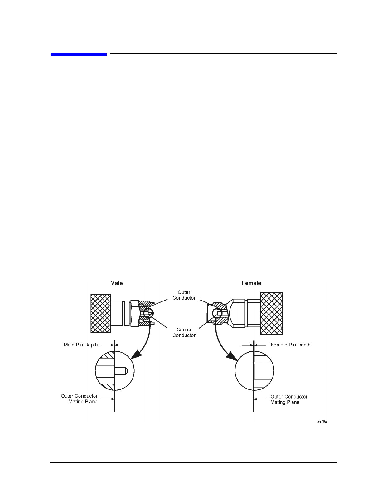
Pin Depth
Pin depth is the distance the center conductor mating plane differs from being flush with
the outer conductor mating plane. See Figure 2-1. The pin depth of a connector can be in
one of two states: either protruding or rec essed.
Protrusion is the condition in which the center conductor extends beyond the outer
conductor mating plane. This condition will indicate a p ositive value on the connector gage.
Recession is the condition in which the center conductor is set back from the outer
conductor mating plane. T his condition will indicate a negative value on the connector
gage.
Figure 2-1 Connector Pin Depth
85056A 2-3

Specifications
Mechanical Characteristics
The pin depth value of each calibration device in the kit is not specified, but is an
important mechanical parameter. The electrical performance of the device depends, to
some extent, on its pin depth. The electrical specifications for each device in the kit take
into account the effect of pin depth on the device’s performance. Table 2-2 lists the typical
pin depths and measurement uncerta inties, and pr ovid es observed pin depth limits for the
devices in the kit. If the pin depth of a device does not measure within the observed pin
depth limits, it may be an indication that the device fails to meet electrical specifi cations.
Refer to Figure 2-1 on pag e 2-3 for a visual representation of proper pin depth (slightly
recessed).
Table 2-2 Pin Depth Limits
Device
Opens 0 to −0.0127 mm
Shorts 0 to −0.0127 mm
Fixe d loads −0.0025 to −0.0203 mm
Sliding loads 0 to −0.0127 mm
Adapters 0 to −0.0381 mm
a. Approximately +2 sigma to −2 sigma of gage uncertainty based on stud ies done at the
factory according to recom m ended procedures.
b. Observed pin depth limits are the range of observation limit s seen on the gage reading due
to measurement uncert ainty. The depth could still be within specif ications.
Typical Pin Dept h
0 to −0.00050 in
0 to −0.00050 in
−0.00010 to −0.00080 in
0 to −0.00050 in
0 to −0.00150 in
Measu rem e n t U n certa in ty
+0.0030 to −0.0030 mm
+0.00012 to −0. 00012 in
+0.0015 to −0.0015 mm
+0.00006 to −0. 00006 in
+0.0030 to −0.0030 mm
+0.00012 to −0. 00012 in
+0.0015 to −0.0015 mm
+0.00006 to −0. 00006 in
+0.0030 to −0.0030 mm
+0.00012 to −0. 00012 in
a
Observed Pin Depth Limits
+0.0030 to −0.0157 mm
+0.00012 to −0.000 62 in
+0.0015 to −0.0142 mm
+0.00006 to −0.000 56 in
+0.0005 to −0.0234 mm
+0.00002 to −0.000 92 in
+0.0015 to −0.0142 mm
+0.00006 to −0.000 56 in
+0.0030 to −0.0411 mm
+0.00012 to −0.001 62 in
b
2-4 85056A

Specifications
Electrical Specifications
Electrical Specifications
The electrical specif ications in Table 2-3 apply to the devices in your calibration kit when
connected with an Agilent precision interface.
Table 2-3 Electrical Specifications for 85056 A 2.4 mm Devices
Device Specifi cation Frequency (GHz)
Broadband loads Return loss ≥ 42 dΒ (ρ ≤ 0.00794) dc to ≤ 4
(male and female) Return loss ≥ 34 dΒ (ρ ≤ 0.01995) > 4 to ≤ 20
Return loss ≥ 30 dB (ρ ≤ 0.0316 2) > 20 to ≤ 26.5
Return loss ≥ 26 dB (ρ ≤ 0.0501 9) > 26.5 to ≤ 50
a
Sliding loads
(male and female) Return loss ≥ 40 dΒ (ρ ≤ 0.01000) > 20 to ≤ 36
Adapters Return loss ≥ 32 dΒ (ρ ≤ 0.02512) dc to ≤ 4
Offset opens
(male and female) ± 1.25 ° devia tion from nominal > 2 to ≤ 20
Offset shorts
(male and female) ± 1.25 ° devia tion from nominal > 2 to ≤ 20
b
b
Return loss ≥ 42 dΒ (ρ ≤ 0.00794) 4 to ≤ 20
Return loss ≥ 38 dB (ρ ≤ 0.0125 9) > 36 to ≤ 40
Return loss ≥ 36 dB (ρ ≤ 0.0158 5) > 40 to ≤ 50
Return loss ≥ 30dΒ (ρ ≤ 0.03162) > 4 to ≤ 26.5
Return loss ≥ 25dB (ρ ≤ 0.05623) > 26.5 to ≤ 40
Return loss ≥ 20 dB (ρ ≤ 0.1000 0) > 40 to ≤ 50
± 0.5 ° deviation from nominal
± 1.75 ° devia tion from nominal > 20 to ≤ 40
± 2.25 ° devia tion from nominal > 40 to ≤ 50
± 0.50 ° devia tion from nominal
± 1.5 ° deviat ion from nominal > 20 to ≤ 40
dc to ≤ 2
dc to ≤ 2
± 2.0 ° deviat ion from nominal > 40 to ≤ 50
a. The specifications for t he sliding load termination incl ude the quality of the airline
portions within t he sliding load combined with the effective stability of the sliding
element.
b. The specifications for the opens and shorts are given as allowed deviation from the
nominal model as defined in the standard definitions (see “Nominal Standard
Definitions” on pageA-8).
85056A 2-5

Specifications
Electrical Specifications
Certification
Agilent Technologies certifies that this product met its p ub li shed s peci fic ations a t the time
of shipment from the factory. Agilent further certifies that its calibration measurements
are traceable to the United States National Institute of Standards and Technology (NIST)
to the extent allowed by the institute’s calibration facility, and to the calibration facilities
of other International Standards Organization m embers. See “How Agilent Verifies the
Devices in Your Kit” on page 4-2 for m o re information.
2-6 85056A

3 Use, Maintenance, and Care of the
Devices
3-1

Use, Maintenance, and Care of the Devices
Electrostatic Discharge
Electrostatic Discharge
Protection against electrostatic discharge (ESD) is essential while connecting, inspecting,
or cleaning connectors attached to a static-sensitive ci rcuit (such as those found in test
sets).
Static electricity can build up on y our body and can easily damage sensitive internal
circuit elements when discharged. Static discharges too small to be felt can cause
permanent damage. Devices such as calibration c omponents and devices under test (DUT),
can also carry an electrostatic charge. To prevent damage to the test set, components, and
devices:
• Always wear a grounded wrist stra p h avi ng a 1 MΩ resistor in series with it when
handling components and devices or when making connections to the test set.
• Always use a grounded antistatic mat in front of your test equipment.
• Always wear a heel strap when working in an area with a conductive floor. If you are
uncertain about the conductivity of your floor, wear a heel strap.
Figure 3-1 shows a typical ESD protection setup using a grounded mat and wrist strap.
Refer to Chapter 6, “Rep laceable Parts,” for information on ordering supplies for ESD
protection.
Figure 3-1 ESD Protection Setup
3-2 85056A

Use, Maintenance, and Care of the Devices
Visual Inspection
Visual Inspection
Visual inspection and, if necessary, cleaning should be done every time a connection is
made. Metal particles from the connector threads may fall into the connector when it is
disconnected. One connection made with a dirty or damaged connector can damage both
connectors beyond repair.
In some cases, m a gnification is necessary to see damage to a connector; a magnifying
device with a magnificati on of ≥ 10× is recommended. However, not all defects that are
visible only under magnification wi ll affect the elec trical per formance of the connector. Use
the following guidelines when evaluating the i ntegrity of a connector.
Look for Obvious Defects and Damage First
Examine the connectors first for obvious defects and damage: badly worn plating on the
connector interface, deformed threads, or bent, broken, or misaligned center conductors.
Connector nuts should move smoothly and be free of burrs, loose metal particles, and
rough spots.
What Causes Connector Wear?
Connector wear is caused by connecting and disconnecting the devices. The more use a
connector gets, the faster it wears and degrades. The wear is greatly accelerated when
connectors are not kept clean, or are not connected properly.
Connector wear eventually d egra des performance of the dev ice. Calibration devices should
have a long life if their use is on the order of a few times per week. Replace d evices with
worn connectors.
The test port connectors on the network analyzer test s et may have many connections each
day, and are therefore more subject to wear. It is recommended that an adapter be used as
a test port saver to m inimize the wear on the test set’s test port connectors.
Inspect the Mating Plane Surfaces
Flat contact between the connectors at a ll point s on their mating plane sur faces is required
for a good connection. See Figure 2-1 on pag e 2-3. Look especially for deep scratches or
dents, and for dirt and metal particles on the connector mating plane surfaces. Also look
for signs of damage due to excessive or uneven wear or misalignment.
Light burnishing of the mating plane surfaces is normal, and is evident as light scratches
or shallow circular marks distributed more or less uniformly over the mating plane
surface. Other small defects and cosmetic imperfections are also normal. None of these
affect electrical or mechanical performance.
If a connector shows deep scratches or dents, particles clinging to the mating plane
surfaces, or uneven wear, clean and inspect it again. Devices with d amaged connectors
should be discarded. Determine the cause of damage before connecting a new, undamaged
connector in the same configuration.
85056A 3-3

Use, Maintenance, and Care of the Devices
Cleaning Connectors
Inspect Female Connectors
Inspect the contact fingers in the female center conductor carefully. These can be bent or
broken, and damage to them is not always easy to see. A connector with damaged contact
fingers will not make good electrical contact and must be repla ced.
NOTE This is particularly important when mating nonprecision to precision devices.
The female 2.4 mm connectors in this calibration kit are metrology-grade, precision
slotless connector s (PSC) . Prec isi on s lotl ess conne cto rs are used to improve accuracy. With
PSCs on test ports and standards, the accuracy achieved when measuring at 50 dB return
loss levels is comparable to using conventi onal slotted connectors measuring devices
having only 30 dB ret urn loss. This represents an accuracy improvement of a bout 10 times.
Conventional female center conductors are slotted and, when mated, are flared by the
male pin. Because physical dimensions determine connector impedance, this change in
physical dimension affects electrical performance, making it very difficult to perform
precision measurements with c onventional slotted female connectors.
The precision slotless connector was developed to eliminate this problem. The PSC has a
center conductor with a solid cylindrical shell, the outside diameter of which does not
change when mated. Instead, this center conductor has an internal contact that flexes to
accept the male pin.
Cleaning Connectors
Clean connectors are essential for ensuring the integrity of RF and microwave coaxial
connections.
1. Use Compressed Air or Nitrogen
WARNING Always use protective eyewear when using compressed air or
nitrogen.
Use compressed air (or nitrogen) to loosen particles on the connector mating plane
surfaces. Clean ai r cannot damage a connector or leave particles or residues behind.
You can use any source of clean, dry, low-pressure compressed air or nitrogen that has
an effective oil-vapor filter and liquid condensation trap placed just before the outlet
hose.
Ground the hose nozzle to prevent electrostatic discharge, and set the air pressure to
less than 414 kP a (60 ps i) to con trol the vel ocity of th e air stream. High- velocity s treams
of compressed air can cause electrostatic effects when directed into a connector. These
electrostatic effects can damage the device. Refer to “Electrostatic Disch arge” on
page 3-2 earlier in this chapter for additional information.
3-4 85056A

Use, Maintenance, and Care of the Devices
Cleaning Connectors
2. Clean the Connector Threads
WARNING Keep isopropyl alcohol away from heat, sparks, and flame. Store in a
tightly closed container. It is extremely flammable. In case of fire , use
alcohol foam, dry chemical, or carbon dioxide; water may be
ineffective.
Use isopropyl alcohol with adequate ventilation and avoid contact
with eyes, skin, and clothing. It causes skin irritation, may cause eye
damage, and is harmful if swallowed or inhaled. It may be harmful if
absorbed through the skin. Wash thoroughly after handling.
In case of spill, soak up with sand or earth. Flush spill area with
water.
Dispose of isopropyl alcohol in accordance with all applicable
federal, state, and local environmental regulations.
Use a lint-free swab or cleaning cloth moistened with i sopropyl alcohol to remove any
dirt or stubborn contaminants on a connector that cannot be removed with compressed
air or nitrogen. Refer to T abl e 6-2 on page 6-3 for part numbers f or isopropy l alcohol and
cleaning swabs.
a. Apply a small amount of isopropyl alcohol to a lint-free cleaning swab.
b. Clean the connector threads.
c. Let the alcohol evaporate, then blow the threads dry with a gentle stream of clean,
low-pressure compressed air or nitrogen. Always completely dry a connector before
you reassemble or use it.
3. Clean the Mat ing Plane Surfaces
a. Apply a small amount of isopropyl alcohol to a lint-free cleaning swab.
b. Clean the center and outer conductor mating plane surfaces. Refer to Figure 2-1 o n
page 2-3. When cleaning a female connector, avoid snagging the swab on the center
conductor contact fingers by using short strokes.
c. Let the alcohol evaporate , then blow the connector dry with a gentle stream of c lea n,
low-pressure compressed air or nitrogen. Always completely dry a connector before
you reassemble or use it.
4. Inspect
Inspect the connecto r t o make sure that no particles or re sid ue r emain. Re fer to “Visual
Inspection” on page 3-3.
85056A 3-5

Use, Maintenance, and Care of the Devices
Gaging Connectors
Gaging Connectors
The gages provided with your cali brat ion ki t are i ntend ed for p re ventive m aintena nce and
troubleshooting purposes only. See Table 6-1 on page 6-2 for part numb e r in fo rmation .
They are effective in detecting excessive center conductor protrusion or recession, and
conductor damage on DUTs, test accessories, and the calibration kit devices . Do not use the
gages for precise p in depth measurements.
Connector Gage Accuracy
The connector gages are only capable of performing coarse measurements. They do not
provide the degree of accuracy necessary to p recisely measure the pin depth of the kit
devices. This is partially due to the repeatabil ity uncertai nties that a re associated with the
measurement. Only the factory—through specia l gaging processes and electrical testing—
can accurately verify the mechanical characteristics of the devices.
With proper technique, the ga ges are useful in detecting gross pin depth errors on device
connectors. To a chieve maximum accuracy, random errors must be reduced by taking the
average of at lea st three measurements having different ga g e orientations on the
connector. Even the resultant average can be in error by as much as ± 0.0001 inch due to
systematic (biasing) er rors usually resulting from worn gages and gage masters. The
information in Table 2-2 on page 2-4 assumes new gages and gage masters. Therefore,
these systematic errors were not included in the uncertainty analysis. As the g ages
undergo more use, the s ystematic er rors can bec ome more significa nt in the a ccuracy of the
measurement.
The measurement uncertainties in Table 2-2 are primarily a function of the assembly
materials and design, and the unique interaction each device type has with the gage.
Therefore, thes e unc ertai nti es can v ary among the different devices. For example, note the
difference between the uncertainties of the opens and shorts in Table 2-2.
The observed pin depth l imits in Table 2-2 add these uncertainties to the typical factory
pin depth values to provide practical limits that can be referenc ed when using the gages.
See “Pin Depth” on page 2-3. Refer to “Kit Contents” on page 1-2 for more information on
the design of the c alibration devices in the kit.
NOTE When measuring pin depth, the m easured value (resultant average of thr ee
or more measurements) is not the true value. Always compare the measured
value with the observed pin depth limits in Table 2-2 to evaluate the
condition of device connectors.
3-6 85056A

Use, Maintenance, and Care of the Devices
Gaging Connectors
When to Gage Connectors
Gage a connector at the following times:
• Prior to using a device for the first tim e: record the pin depth measurement so that it
can be compared with future r eadings. ( It will serve as a good troub leshooting tool when
you suspect damage may have occurred to the d evice.)
• If either visual inspection or electrical performance suggests that the connector
interface may be out of typical range (due to wear or damage, for example).
• If a calibration device is used by someone else or on another system or piece of
equipment.
• Initially after every 100 connections, a nd after that as often as experience indicates.
85056A 3-7

Use, Maintenance, and Care of the Devices
Gaging Connectors
Gaging Procedures
Gaging 2.4 mm Connectors
NOTE Always hold a connector gage by the ga ge barrel, below the dial indicator.
This gives the best stability, and improves measurement accuracy. (Cradling
the gage in your hand or holding it by the dial applies stress to the gage
plunger mechanism through the dial indicator housing.)
1. Select the proper gage for your connector. Refer to Table 6-1 on page 6-2 for gage part
numbers.
2. Inspect and clean the gage, gage master, and device to be gaged. Refer to “Visual
Inspection” and “Cleaning Connectors” earlier in this chapter.
3. Zero the connector gage (refer to Figure 3-2):
a. While holding the gage by the barrel, and without turning the gage or the device,
connect the gage to the gage master by interconnecting the male and female
connectors. Connect the nut finger tight. Do not overtighten.
b. Using an open-end wrench to keep the device body from rotating, use the torque
wrench included in the kit to tighten th e connect ing nut t o the specifi ed torque . Ref er
to “Final Connection Using a Torque Wrench” on page 3-14 for additional
information.
c. As you watch the gage pointer, gently tap the b arrel of the gage to settle the reading.
The gage pointer should line up exa ctly with the zero mark on the gage . If not, a djust
the zero set knob until the gage pointer lines up exactly with the zero mark.
d. Remove the gage master.
4. Gage the device connector (refer to Figure 3 - 2):
a. While holding the gage by the barrel, and without turning the gage or the device,
connect the gage to the device by interconnecting the male and female connectors.
Connect the nut finger-ti ght. Do not overtighten.
b. Using an open-end wrench to keep the device body from rotating, use the torque
wrench included in the kit to tighten th e connect ing nut t o the specifi ed torque . Ref er
to “Final Connection Using a Torque Wrench” on page 3-14 for additional
information.
c. Gently tap the barrel of the gage with your finger to settle the gage reading.
d. Read the gage indicator dial. Read only the black ± signs; not the red ± signs.
For maximum accuracy, measure the connector a minimum of three times and take
an average of the read ings. After each measurement, r otate the gage a quarter-turn
to reduce measurement variati ons that result f rom the gage or t he connector face not
being exactly perpendicular to the center axis.
e. Compare the average reading with the o bserved pin d epth limits i n T a ble 2-2 on page
2-4.
3-8 85056A
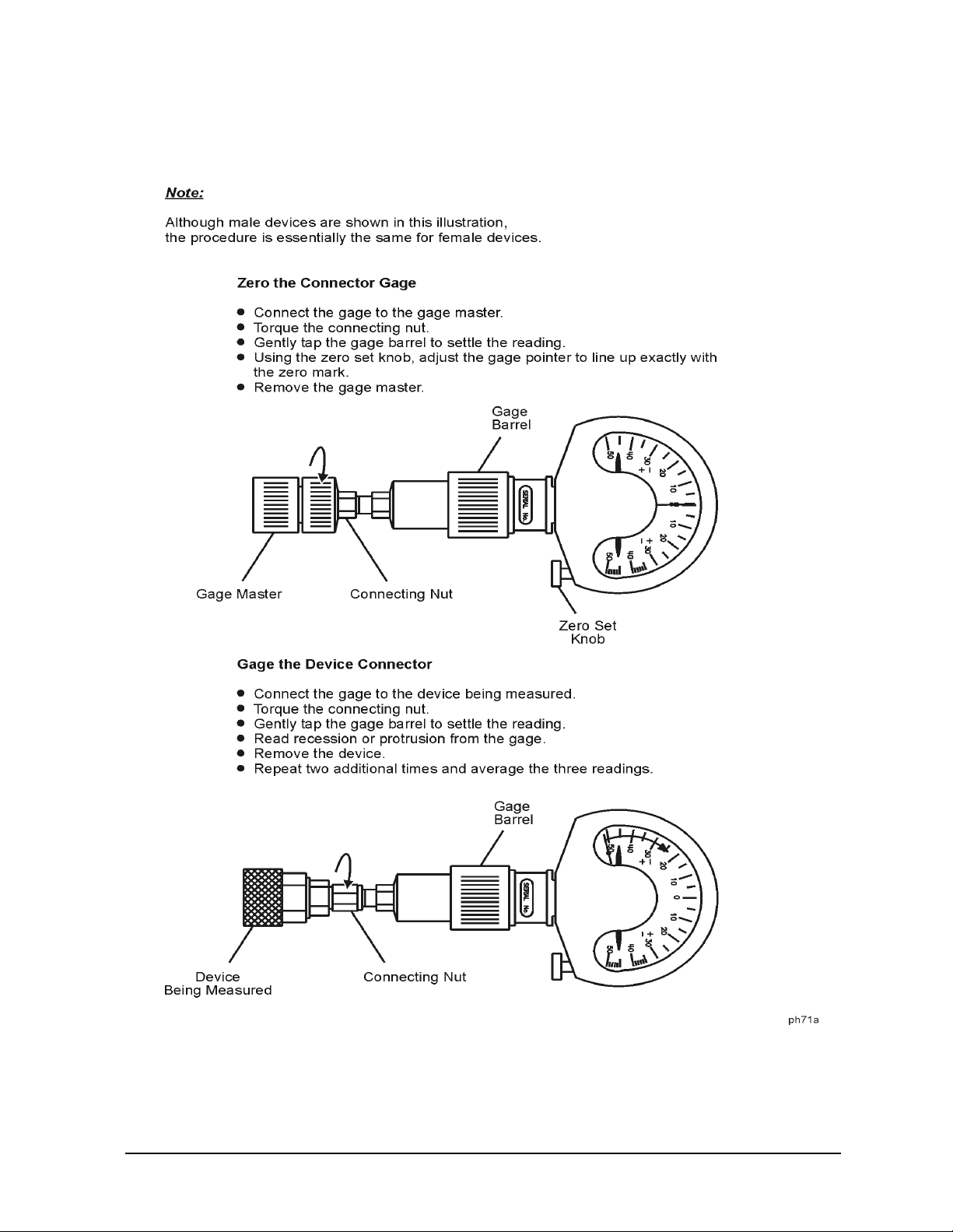
Figure 3-2 Gaging 2.4 mm Connectors
Use, Maintenance, and Care of the Devices
Gaging Connectors
85056A 3-9

Use, Maintenance, and Care of the Devices
Gaging Connectors
Gaging the 2.4 mm Sliding Loads
Gage the sliding load before each use. If the sliding load pin depth i s out of the observed
pin depth limits listed in Table 2-2 on page 2-4, refer to “Adjus ti ng the Sliding Load Pin
Depth” on page 3-12.
NOTE Always hold a connector gage by the ga ge barrel, below the dial indicator.
This gives the best stability, and improves measurement accuracy. (Cradling
the gage in your hand or holding it by the dial applies stress to the gage
plunger mechanism through the dial indicator housing.)
1. Select the proper gage for your connector. Refer to Table 6-1 on page 6-2 for gage part
numbers.
2. Inspect and clean the gage, gage master, and device to be gaged. Refer to “Visual
Inspection” on page 3-3 and “Cleaning Connectors” on page 3-4 earlier in this chapter.
3. Zero the connector gage (refer to Figure 3-2 on page 3-9):
a. While holding the gage by the barrel, and without turning the gage or the device,
connect the gage to the gage master by interconnecting the male and female
connectors. Connect the nut finger-tight. Do not overtighten.
b. Using an open-end wrench to keep the device body from rotating, use the torque
wrench included in the kit to tighten th e connect ing nut t o the specifi ed torque . Ref er
to “Final Connection Using a Torque Wrench” on page 3-14 for additional
information.
c. As you watch the gage pointer, gently tap the b arrel of the gage to settle the reading.
The gage pointer should line up exa ctly with the zero mark on the gage . If not, a djust
the zero set knob until the gage pointer lines up exactly with the zero mark.
d. Remove the gage master.
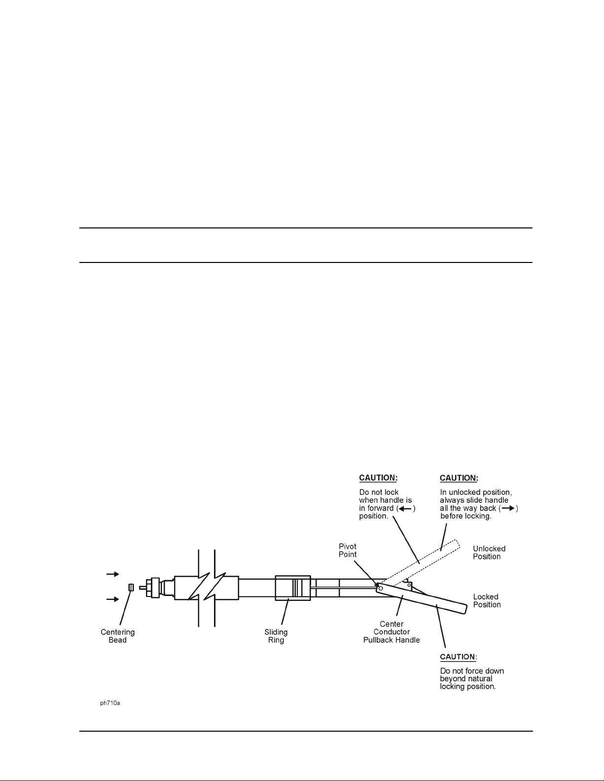
4. Gage the sliding load connector (refer to Figure 3-3):
a. Unlock the center conductor pullback mechanism by raising the pullback handle to
the unlocked position.
b. Carefully move the p ullback m echanism t oward the connector end of t he sliding load.
The center conductor will extend beyond the end of the connector. Continue to hold
the pullback mechanism in this position.
c. Pull the sliding ring back approximately 0.5 in and install a centering bead in the
connector end of the sliding load.
CAUTION The sliding load center conductor can be damaged if the sliding load is not in
alignment with the mating connector while making the connection.
d. Keep the center conductor extended by holding the center conductor pullback
mechanism toward the connector end of the sliding load. Align the sliding load with
the mating connector on the gage and mate the sliding load center conductor with
the gage center conductor.
3-10 85056A
Use, Maintenance, and Care of the Devices
Gaging Connectors
e. Release the center conductor pullback mechanism and move the body of the sliding
load toward the gage to mate the outer conductor of the sliding load connector with
the outer conductor of the gage connector.
f. Without turning the gage or the sliding load, connect the gage to the sli ding load
being measured by i nter connecti ng the male and female connec tor s. Connect the nut
finger-tight. Do not overtighten.
g. Using an open-end wrench to keep the device body from rotating, use the torque
wrench included in the kit t o tighten the c onnecti ng nut to t he specified t orque . Refer
to “Final Connection Using a Torque Wrench” on page 3-14 for additional
inform at io n .
CAUTION Always move the center conductor pullback mechanism back before locking
the handle. Do not force the handle past the locked position.
h. Mov e the center conductor pullback mechanism back (away from the connector end
of the sliding load), and place the pullback handle in its locked position.
i. Gently tap the barrel of the gage with your finger to settle the gage reading.
j. Read the gage indicator dial. Read only the black ± signs; not the red ± signs.
For maximum accuracy, measure the connector a minimum of three times and take
an average of the readings. Use different orientations of the gage within the
connector. After each measurement, rotate the gage a quarter-turn to reduce
measurement variations that result from the gage or the connector face not being
exactly perpendicular to the center axis.
k. Compare t he ave rage reading with t he obse rved pin depth l imits in T able 2-2 on page
2-4. If the pin depth is outside the l imits, it must be adjusted before proceeding.
Refer to “Adjusting the Sliding Load Pin Depth” on page 3-12.
Figure 3-3 Gaging the 2.4 mm Sliding Loads
85056A 3-11

Use, Maintenance, and Care of the Devices
Gaging Connectors
l. Without turning the gage or the sliding load, loosen the connection between the gage
and the sliding load and remove the sliding load from the gage.
CAUTION Remove the centering bead immediately after gaging the sliding load pin
depth. Damage can occur to the sliding load during the remova l of a centering
bead that has slipped too far into the s liding load. The sliding load will not
perform to its specifications if the centering bead is not removed before an
electrical calib ration is performed.
m.Carefully remove the centering bead from the sliding load. If the centering bead does
not come out of the s liding load easily:
i. Unlock the center conductor pullback handle a nd move the center conductor
pullb ack mechanism toward the connector end of the sliding load to extend the
center conductor.
ii. While holding the center conductor pullback mechanism toward the connector end
of the sliding load, remove the centering b ead.
If the centering bead still will not come out:
i. Hold the sliding load with the connector end pointed downward.
ii. Move the sliding ring up, then quic kly down. The trapped air behind the centering
bead should eject it.
Return the center conductor pullback mechanism to the rear of the sliding load and
return the pullback handle to its locked position.
Adjusting the Sliding Load Pin Depth
The sliding loads in this kit have a setback mechanism that allows the pin depth to be set
to any desired value. The pin depth of the sliding load is preset at the factory. The pi n
depth should not have to be r eset each t ime the sli ding load is us ed, but it should be checked
before ea ch use.
If the pin depth is outside the observed limits listed in Table 2-2 on page 2-4, use the
following procedure to r eset it to the nominal value of −0.00381 mm (−0.00015 in).
This procedure assumes that you were directed here from “Gaging the 2 .4 mm Sliding
Loads” on page 3-10. If not, perform the steps in that procedure before performing this
procedure.
1. The gage should be attached to the sliding load. Refer to “Gaging th e 2. 4 mm Slid ing
Loads” on pag e 3-10 if necessary.
2. The face of the g age and the label on the sliding load should be facing up.
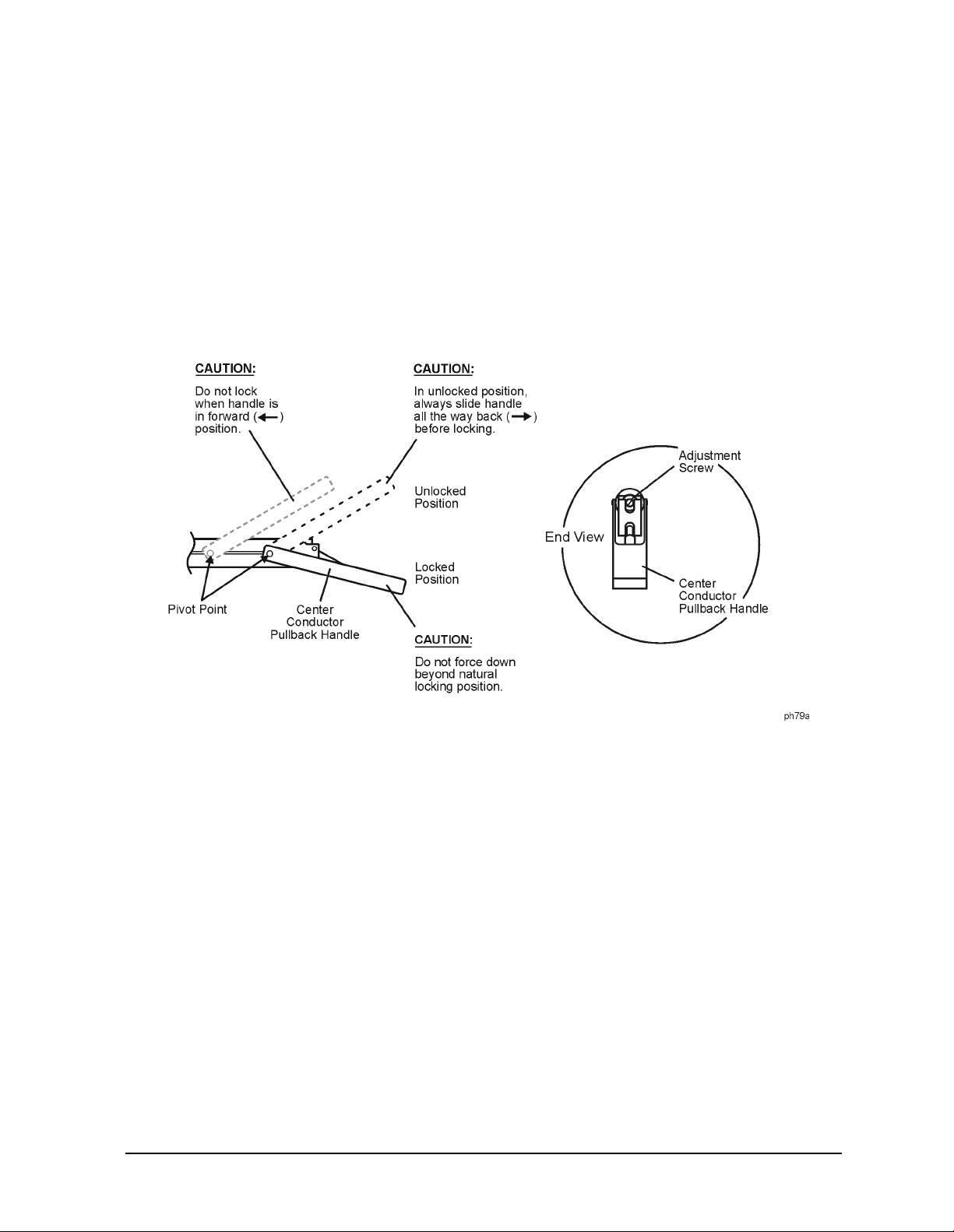
3. The center conductor pullback handle should be in the locked position.
4. With a small screwdriver, gently turn the center conductor pin depth adjus tme nt screw
until the gage pointer reads −0.00381 mm (−0.00015 in). Refer to Figu re 3-4 for the
location of the adjustment screw.
5. Wait approximately five minutes to allow the temperature to stabilize. Do not touch
either the gage or the sliding load during this time.
3-12 85056A
Use, Maintenance, and Care of the Devices
Gaging Connectors
6. Note the gage reading. If it is no longer within the allowable range, perform step 4
again.
7. Move the center conductor pullback handle to the unlocked position and then back to
the locked position. The gage reading should return to the value previously set. If not,
repeat steps 4 through 7.
8. Return to “Gaging the 2.4 mm Sliding Loads” on page 3-10.
Figure 3-4 Adjusting the Sliding Load Pin Depth
85056A 3-13

Use, Maintenance, and Care of the Devices
Connections
Connections
Good connections require a skill ed op erator. The most common cause of me asu rement error
is bad connections. The following procedures illustrate how to make good connections.
How to Make a Connection
Preliminary Connection
1. Ground yourself and all devices. Wear a grounded wrist strap and work on a grounded,
conductive table mat. Refer to “Electrostatic Discharge” on page 3-2 for ESD
precautions.
2. Visually inspect the connectors. Refer to “Visual Inspection” on page 3-3.
3. If necessary, clean the connectors. Refer to “Cleaning Connectors” on page 3-4.
4. Use a connector gage to verify that all center conductors are within the observed pin
depth values in Table 2-2 on pa ge 2-4. Refer to “Gaging Connectors” on page 3-6.
5. Carefully align the connectors. The male connector center pin must slip concentrically
into the contact fing er of the female connector.
6. Push the connectors straight together and tighten the connector nut finger tight.
CAUTION Do not turn the device body. Only turn the connector nut. Damage to the
center conductor can occur if the device body is twisted.
Do not twist or screw the connectors together. As the center conductors mate, there is
usually a slight resistance.
7. The preliminary connection is tight enoug h when the mating plane surfaces make
uniform, light contact. D o not overtighten this connection.
A connection in which the outer conductors make gentle contact at all points on both
mating surfaces is suffi cient. Very light finger pressure is enough to accomplish this.
8. Make sure the connectors are properly supported. Relieve any side pressure on the
connection from long or heavy devices or ca bles.
Final Connection Using a Torque Wrench
Use a torque wrench to m ake a final connection. Table 3-1 provides information about the
torque wrench recommended for use with the calibration kit. A torq ue wrench is included
in the calibration kit. Refer to Ta bl e 6-1 o n page 6-2 for replacement part number and
ordering i n fo rmation.
Ta ble 3-1 Torque Wrench Information
Connector Type Torque Setting Torque Tolerance
2.4 mm 90 N-cm (8 in-lb) ± 9.0 N-cm (± 0.8 in-lb)
3-14 85056A
Use, Maintenance, and Care of the Devices
Connections
Using a torque wrench guarantees that the c onnec tion is not too tight, prev entin g pos sible
connector damage. It also guarantees that all connections are equally tight each time.
Prevent the rotation of any thing other than the connector nut that you are tightening. It
may be possible to do this by hand if one of the connectors is fixed (as on a tes t port).
However, it is recommended that you use a n open-end wrench to keep the body of the
device from turning.
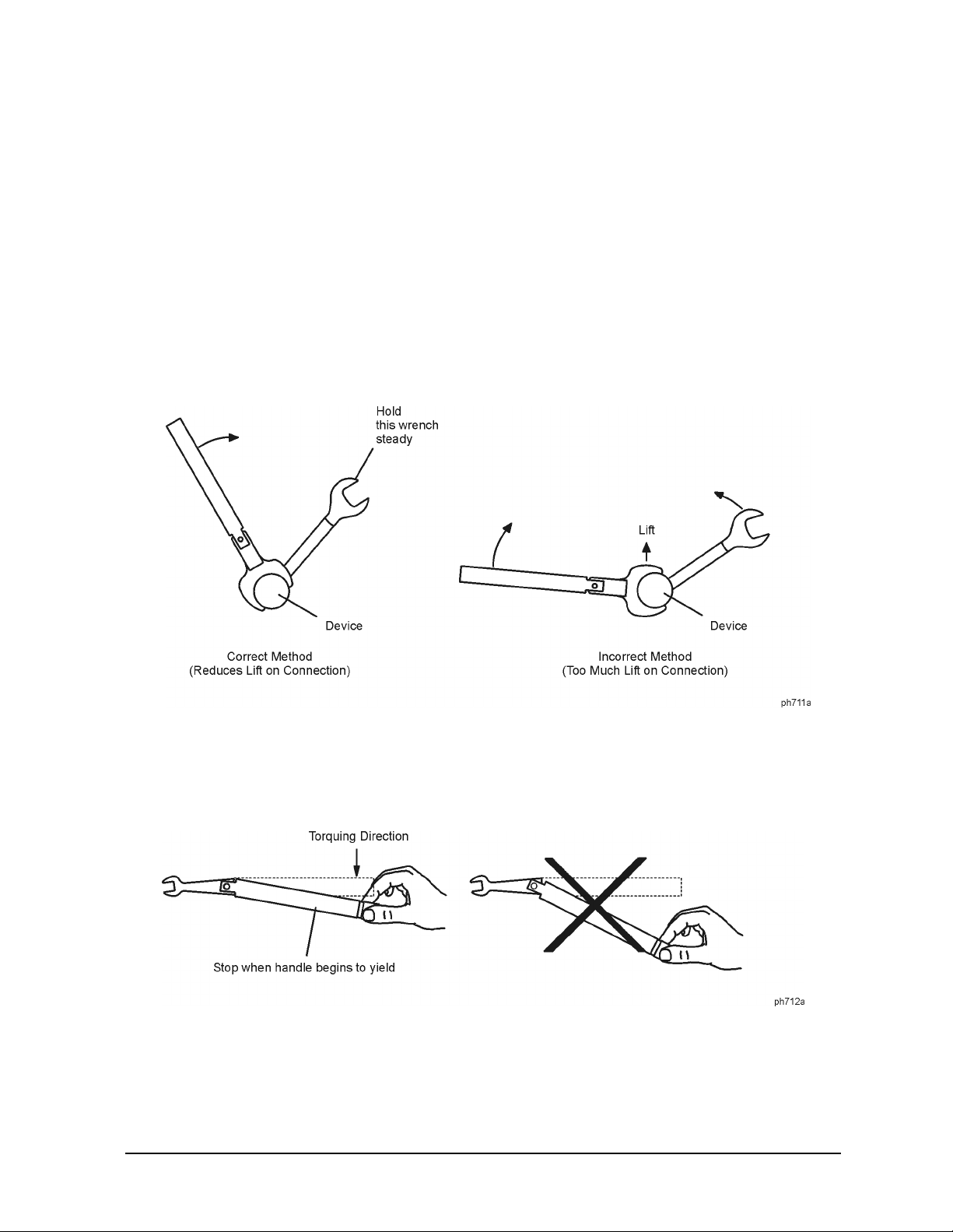
1. Position both wrenches within 9 0 degrees of each other before applying force. See
Figure 3-5 . Wrenches opposing each other (greater than 90 degrees apart) will cause a
lifting action which can misalign and stress the connections of the devices involved.
This is especially true when several devices are connected tog ether.
Figure 3-5 Wrench Positions
2. Hold the torque wrench lightly, at the end of the handle only (beyond the groove). See
Figure 3-6 .
Figure 3-6 Using the Torque Wre n ch
3. Apply downward force pe rpendicul ar to the wrench h an dl e. Th is applies torqu e t o the
connection through the wrench.
Do not hold the wrench so tightly that you push the handle straight down along its
length rather than pivoting it, otherwise you apply an unknown amount of torque.
85056A 3-15

Use, Maintenance, and Care of the Devices
Connections
4. Tighten the connection just to the torque wrench break point. The wrench handle gives
way at its internal pivot point. See Figure 3-6 on pa ge 3-15. Do not tighten the
connection further.
CAUTION You don’t have to fully break the handle of the torque wrench to reach the
specified torque; doing so can cause the ha ndle to kick back and loosen the
connection. Any give a t all in the handle is sufficient torque.
Connecting the Sliding Load
1. Unlock the center conductor pullback m echanism by raising the pullback handle to the
unlocked position. Refer to Figu re 3-7.
2. Carefully move the pullback mechanism toward the connector end of the sliding load.
The center conductor will extend beyond the end of the conductor. Continue to hold the
pullb ack mechanism in this p o sit io n .
CAUTION The sliding load center conductor can be damaged if the sliding load is not in
alignment with the mating connector while making the connection.
3. Keep the center conductor extended by holding the center conductor pullback
mechanism toward the connec tor end of t he s liding l oa d. Align the sliding load with the
mating connector on the cable or test port to w hich it is being connected and mate the
sliding load center conductor with the center conductor of the cable or test port.
4. Release the center conductor pull back mechanism and move the body of the sliding load
toward the ca ble or test port to mate the outer conductor of the sliding loa d c onnec tor to
the outer conductor of the cable or test port connector.
5. Without turning the sliding load, connect the sliding load to the cable or test port by
interconnecting the male and female connectors. Connect the nut finger-tight. Do not
overtighten.
6. Using an open-end wrench to keep the device body from rotating , use the torque wrench
included in the kit to tighten the connecting nut to the specified torque. Refer to “Final
Connection Using a Torque Wrench” on page 3-14 for additional information.
CAUTION Always move the center conductor pullback mechanism back before locking
the handle. Do not force the handle past the locked position.
7. Move the center conductor pullback mechani sm back (away from the connector end of
the sliding load), a nd place the pullback handle in its locked position.
3-16 85056A

Figure 3-7 Connecting the Sliding Load
Use, Maintenance, and Care of the Devices
Connections
How to Separate a Connection
To a void l ateral (bending) f orce on the connecto r mating plane surf aces, alw ays support the
devices and connections.
CAUTION Do not turn the device body. Only turn the connector nut. Damage to the
center conductor can occur if the device body is twisted.
If disconnecting a sliding load, leave the center conductor pullback handle in the locked
position.
1. Use an open-end wrench to pr event the device body from turning.
2. Use another open-end wrench to loosen the connecting nut.
3. Complete the separation b y hand, turning only the connecting nut.
4. Pull the connectors straight apart without tw isting, rocking, or bending either of the
connectors.
85056A 3-17

Use, Maintenance, and Care of the Devices
Using the Sliding Load
Using the Sliding Load
When performing a sliding load calibration, it is recommended that the sliding ring be set
at the marked positions ( rings) along the sliding load body. Using the set marks ensures
that a broad distrib ution of phase angles is selected, ther eby optimizing the calibration.
The set marks function a s detents so that the internal center of the sliding r ing can mate
with them. Because of this , the set m ark being used cannot be seen bu t is felt as the sliding
ring is moved from mark to mark during a calibration. Moving the sli ding ring with only
the index fingers of bot h hands will i ncrease your abi lity to det ect the slid ing ring detent at
each position.
To perfor m a sliding l oad cali bration, r efer to y our network analyzer s user’ s documentation
for instr u ct io n s.
Figure 3-8 Sliding Load Set Marks
Handling and Storage
• Do install the protective end caps and stor e the calibration devices in the foam-lined
storage case when not in us e.
• Do keep connectors clean.
• Do not touch mating plane surfaces. Na tural skin oils and microscopic particles of dirt
are easily transferred to a connector interface and are very difficult to remove.
• Do not set connectors contact-end down on a har d surface. The plating and the m a ting
plane surfaces can be damaged if the interface comes in contact with any hard surface.
• Do not store connectors loose in a box, or in a desk or bench drawer. This is the most
common cause of connector damage during storage.
3-18 85056A

4 Performance Verification
4-1

Performance Verification
Introduction
Introduction
The performance of your calibra tion kit can only be verified by r etur ning the kit to Agilent
Technologies for recertification. The equipment required to verify the specifications of the
devices in the kit has been specially manufactured and is not commercially available.
How Agil ent Verifies the Devices i n Your Kit
Agilent verifies the specifications of these devices as follows:
1. The residual microwave error term s of the test system are verified with precision
airlines and shorts tha t are directly traced to the National Institute of Standards and
Tec hnology (NIST). The airline and short characteristics are developed from mechanical
measurements. The mechanical measurements and material properties are carefully
modeled to give very accurate electrical representa tion. The mechanical measurements
are then traced to NIST through various plug and ring gages and other mechanical
measurements.
2. Each calibration device is electri cally tested on this system. For the initial (before sale)
testing of the ca li brat ion de vi ces , Agilent includes the test measureme nt unc er tainty a s
a guardband to guarantee each device meets the published specification. For
recertifications (after sale), no guardband is used and the measured data is compared
directly with the specification to determine the pass or fail status. The measurement
uncertainty for each device is, however, recorded in the calibration report that
accompanies recertified k it s.
These two steps establish a traceable link to NIST for Agilent to the extent allowed by the
institute’s calibration facility. The specifications data provided for the devices in the kit is
traceable to NIST through Agilent Technologies.
4-2 85056A

Performance Verification
Recertification
Recertific at ion
The following will be provided with a recertified kit:
• a new calibration sticker affixed to the case
• a certificate of calibrat i on
• a calibration report for each device in the kit listing measured values, specifications,
and uncertainties
NOTE A list of NIST traceable numbers may be purchased upon request to be
included in the calibration report.
Agilent Technologies offers a Standard calibration for the recertification of the kit. For
more information, contact Agi lent Technologies. See Table 5-1 on page 5-4 fo r co n t act
inform at io n.
How Often to Recertify
The suggested initial inter val fo r recertifi cation i s 12 months or sooner. The actual need for
recertification depends on the use of the kit. After reviewing the results of the initial
recertification, you may establi sh a different recertif ication inter val that reflects the usage
and wear of the kit.
NOTE The recertification interva l should begin on the date the kit is first used after
the recertification date.
Where to Send a Kit for Recertification
Contact Agilent Technologies for information on where to send your kit for recertification.
Contact information is listed on page 5-4. Refer to “Returning a Kit or Device to Agilent”
on page 5-3 for details on sending your kit.
85056A 4-3

Performance Verification
Recertification
4-4 85056A

5 Troubleshooting
5-1

Troubleshooting
Troubleshooting Process
Troubleshooting Process
If you suspect a bad calibration, or if your network analyzer does not pass performance
verification, follow the steps in Figure 5-1.
Figure 5-1 Troubleshooting Flowchart
5-2 85056A

Troubleshooting
Returning a Kit or Device to Agilent
Returning a K it or Device to Agilent
If your kit or device requires service, contact Agilent Technologies for information on
where to send it. See Table 5-1 for contact information. Include a service tag (located near
the end of this manual) on which you provide the following information:
• your company name and address
• a technical contact person within your company, and the person's complete phone
number
• the model number and serial number of the kit
• the part number and serial number of each device
• the type of service required
•a detailed description of the problem and how the device was being used when the
problem occurred (such as calibration or measurement)
Contacting Agilent
Table 5-1 Contacting Agilent
Online assistance: www.agilent.com/find/assist
United States
(tel) 1 800 452 4844
New Zealand
(tel) 0 800 738 378
(fax) (+64) 4 495 8950
Malaysia
(tel) 1 800 828 848
(fax) 1 800 801 664
Taiwan
(tel) 0800-047-866
(fax) (886) 2 25456723
Latin America
(tel) (305) 269 7500
(fax) (305) 269 7599
Japan
(tel) (+81) 426 56 7832
(fax) (+81) 426 56 7840
Philippines
(tel) (632) 8426802
(tel) (
PLDT subscriber only):
1 800 16510170
(fax) (632) 8426809
(fax) (
PLDT subscriber on ly):
1 800 16510288
People’s Republic of
China
(tel) (preferred):
800-810-0189
(tel) (alternate):
10800-650-0021
(fax) 10800-650-0121
Canada
(tel) 1 877 894 4414
(fax) (905) 282-6495
Australia
(tel) 1 800 629 485
(fax) (+6 1) 3 9210 5947
Thailand
(tel) outside Bangkok:
(088) 226 008
(tel) with in Bangkok:
(662) 661 3999
(fax) (66) 1 661 3714
India
(tel) 1-600-11-2929
(fax) 000-800-650-1101
Europe
(tel) (+31) 20 547 2323
(fax) (+31) 20 547 2390
Singapore
(tel) 1 800 375 8100
(fax) (65) 836 0252
Hong Kong
(tel) 800 930 871
(fax) (852) 2506 9233
85056A 5-3

Troubleshooting
Returning a Kit or Device to Agilent
5-4 85056A

6 Replaceable Parts
6-1

Replaceable Parts
Introduction
Introduction
Table 6-1 lists the replacem ent part numbers for items included in the 85056A calibration
kit and Figure 6-1 and Figure 6-2 illustrate each of these items.
Table 6-2 lists the replacem ent part numbers for items not included in the calibration kit
that are either required or recommended for suc cessful operation of the kit.
To or der a listed part, note the description, the part number, and the quantity desired.
Tel ephone or send your order to Agilent T ec hnologies . See Table 5-1 on page 5-3 for contac t
information.
Table 6-1 Replaceable Parts for the 85056A Calibration Kit
Description Qty
per kit
Calibration Devices (2.4 mm)
Male broadband load 1 00901-60003
Fe male broadband load 1 00901-60004
Male sliding load 1 00915-60003
Fe male sliding load 1 00915-60004
Male offset open 1 85056-60022
Female offset open 1 85056-60023
Male offset short 1 85056-60020
Female offset short 1 85056-60021
Adapters (2.4 mm)
Male to male 1 85056-60005
Male to female 1 85056-60006
Fe male to female 1 85056-60007
Connector Gages (2.4 mm)
Agilent Part
Number
Male gage set (includes gage master) 1 11752-60108
Female gage set (includes gage master) 1 11752-60107
Centering bead (for gag ing the 2.4 mm sliding loads) 1 85056-20001
Calibration Kit Storage Case
Box (including foam pads) 1 85056-60014
Box (without foam pads ) 1 5180-8419
Fo am pad (f or lid) 1 5181-5542
Fo am pad (f or lower case) 1 85056-80009
6-2 85056A

Table 6-1 Replaceable Parts for the 85056A Calibration Kit
Replaceable Parts
Introduction
Desc ription Qty
per kit
Wrenches
5/16 in, 90 N-cm (8 in-lb) torque wrench 1 8710-1765
7 mm open-end wrench 1 8710-1761
Misc ella neous Items
Calibration definitions disk (8510 and 872x) 1 85056-10003
Calibration definitions disk (PNA series)
Specificatio ns and performance verification disk 1 08510- 10033
User’s and service guide 1 85056-90020
1
Agilent Part
Number
85056-10009
Table 6-2 Items Not Included in the Calibration Kit
Description Qty Agilent Part
Number
Open-End Wre nc h
5/16 in open-end wrench 1 8720-0015
ESD Protection Devices
Grounding wrist strap 1 9300-1 367
5 ft grounding cord for wrist strap 1 9300-0 980
2 ft by 4 ft conductive table m at w i th 15 ft grounding wire 1 9300-0 797
ESD heel strap 1 9300-1 308
Connector Cleaning Supplies
Isopropyl alcohol 30 ml 8500-5344
Foam- tipped cleaning swabs 100 9301-1243
85056A 6-3

Replaceable Parts
Introduction
Figure 6-1 Rep laceable Parts for the 85056A Calibration Kit
6-4 85056A

Figure 6-2 Replaceable Parts for the 85056A Calibration Kit
Replaceable Parts
Introduction
85056A 6-5

Replaceable Parts
Introduction
6-6 85056A

A Standard Definitions
A-1

Standard Definitions
Standard Class Assignments
Standard C l ass Assignments
Class assignment organizes calibration standards into a format compatible with the error
models used in the measu rement c alibration. A class or group of classe s corr es ponds to the
systematic errors to be removed from the measured network analyzer response. T ables A-1
through A-3 list the classes of the devices in the kit for various network analyzers. This
information resides on the calibration data included in the ki t.
Table A-1 Standard Class Assignments for the 8510 Network Analyzer
Disk File Name: CK_24MMA4 Calibration Kit Label: 2.4 mm A.4
Class
S11A2 Open
S
B1 Short
11
S
C 9 10 12 Loads
11
S
A2 Open
22
S
B1 Short
22
S
C 9 10 12 Loads
22
Forward transmission 11 Thru
Reverse transmission 11 Thru
For wa rd ma tc h 11 Thru
Reverse match 11 Thru
Forward isolation
Reverse isol ation 9 Isol’n Std
Frequency res ponse 1 2 11 Response
TRL thru 14 Undefined
TRL reflect 1 Undefined
a
A B C D E F G
9 Isol’n Std
Standard Class Label
TRL line 15 16 17 Undefined
Adapter 13 Adapter
TRL Option
Cal Z
: _____ System Z0 __X__ Line Z
0
Set ref: __X__ Thru _____ Reflect
Lowband freque ncy : ________ _
a. The forward isolation standard is also used for the isolation part of the response and isolation
calibration.
__
0
A-2 85056A

Standard Definitions
Standard Class Assignments
Table A-2 Standard Class Assignments for the 872x Series Network Analyzer
Calibration Kit Labe l: 2.4 mm
Class
A B C D E F G
Standard Class Label
S11A2 Open
S
B1 Short
11
S
C356 Loads
11
S
A2 Open
22
S
B1 Short
22
S
C356 Loads
22
Forward transmission 4 Thru
Reverse transmission 4 Thru
Forward match 4 Thru
Reverse match 4 Thru
Response 1 2 4 Response
Response & isolation 1 2 4 Response
TRL thru 4 Undefined
TRL reflect 2 Undefined
TRL line 3 5 6 Undefined
TRL Option
Cal Z
: _____ System Z0 __X__ Line Z
0
0
Set ref: __X__ Thru _____ Reflect
85056A A-3

Standard Definitions
Standard Class Assignments
Table A-3 Standard Class Assignments for the PNA Series Network Analyzer
Calibration Kit Label:
2.4 mm Model 85056A
Class A
A2
S
11
S
B1
11
S
C 3, 5, 6
11
S
T4
21
S
A2
22
S
B1
22
S
C 3, 5, 6
22
S
T4
12
TRL ‘T’ 4
TRL ‘R’ 2
TRL ‘L’ 3, 5, 6
Notes:
1. If you are performing a TRL calibration:
•S
•S
•S
T and S12T must be def ine d as thru standar ds.
21
A and S22A must be defined as reflection standards.
11
B, S11C, S22B, and S22C must be defined as line standa rds.
11
2. If you are performing a TRM calibration:
•S
•S
•S
T and S12T must be def ine d as thru standar ds.
21
A and S22A must be defined as reflection standards.
11
B, S11C, S22B, and S22C must be defined as match standar ds.
11
3. If you are performing an LRM calibration:
•S
•S
T and S12T must be def ine d as line standards.
21
A and S22A must be defined as reflection standards.
11
•S
4. S
5. S
B, S11C, S22B, and S22C must be defined as match standar ds.
11
B and S11C must be defined as the same standard.
11
B and S22C must be defined as the same standard.
22
For additional information on performing TRL, TRM, and LRM calibrations, refer to your
PNA series network analyzer embedded help system.
A-4 85056A

Standard Definitions
Standard Class Assignments
Blank Forms
The standard class assignments may be changed to m eet your specific requirements.
Tables A-4 through A-5 are provided to record the modified standard class assignments.
Table A-4 Blank Form for the 8510 Network Analy zer
Disk File Name: ____________________ Calibration Kit Label: ________________
Class
S11A
S
B
11
S
C
11
S
A
22
S
B
22
S
C
22
Forward transmission
Reverse transmission
Forward match
Reverse match
Forward isolation
Reverse isolation
Frequency response
TRL thru
a
A B C D E F G
Standard Class Label
TRL reflect
TRL line
Adapter
TRL Option
Cal Z
: _____ System Z
0
Set ref: _____ Thru _____ Reflect
Lowband frequency: _________
a. The forward isolation standard is also used for the isolation part of the response and isolation
calibration.
0
_____ Line Z
__
0
85056A A-5

Standard Definitions
Standard Class Assignments
Table A-5 Blank Form for the 872x Series Network Analyzer
Calibration Kit Label: ________________
Class
S11A
S
B
11
S
C
11
S
A
22
S
B
22
S
C
22
Forward transmission
Reverse transmission
For wa rd ma tc h
Reverse match
Response
Response & isolation
TRL thru
TRL reflect
A B C D E F G
Standard Class Label
TRL line
TRL Option
Cal Z
: _____ System Z0 _____ Line Z
0
Set ref: _____ Thru _____ Reflect
Lowband freque ncy : ________ _
__
0
A-6 85056A

Table A-6 Blank Form for the PNA Series Network Analyzer
Calibration Kit Label:
________________ ____
Class A
S11A
S
B
11
S
C
11
S
T
21
S
A
22
S
B
22
S
C
22
S
T
12
TRL ‘T’
Standard Definitions
Standard Class Assignments
TRL ‘R’
TRL ‘L’
Notes:
1. If you are performing a TRL calibration:
•S
•S
•S
T and S12T must be defi n ed as th ru st andards.
21
A and S22A must be defined as reflection st an dards.
11
B, S11C, S22B, and S22C must be defined as line stan dards.
11
2. If you are performing a TRM calibration:
•S
•S
•S
T and S12T must be defi n ed as th ru st andards.
21
A and S22A must be defined as reflection st an dards.
11
B, S11C, S22B, and S22C must be defined as match standards.
11
3. If you are performing an LRM calibration:
•S
•S
T and S12T must be defi n ed as lin e standards.
21
A and S22A must be defined as reflection st an dards.
11
•S
4. S
5. S
B, S11C, S22B, and S22C must be defined as match standards.
11
B and S11C must be defined as the same standard.
11
B and S22C must be defined as the same standard.
22
For additional info rmation on pe rfo rming T R L, TR M , an d LRM ca libration s, refe r t o y o u r
PNA series network analyzer embedded help system.
85056A A-7

Standard Definitions
Nominal Standard Defini ti ons
Nominal Standard Definitions
Standard definitions provide the constants needed to mathematically model the electrical
characteristics (delay, attenuation, and impedance) of each calibration standard. The
nominal values of these constants are theoretically derived from the physical dimensions
and material of each cali bration standard , or from actua l measured response. These values
are used to determine the measurement uncertainties of the network analyzer. The
standard definitions in Tables A-7 through A-9 list typical calibration kit parameters used
to specify the mathematical model of each device . This infor mation must be loaded into the
network analyzer to perform valid calibrations. Refer to your network analyzer user’s
documentation for instructions on loading c alibration definitions.
NOTE The values in the standard definitions table are valid only over the specified
operating temperature range.
Setting the System Impedance
This kit contains only 50 ohm devices. Ensure the system impedance (Z0) is set to 50 ohms.
Refer to your network analyzer user’s documentation for instr uctions on setting system
impedance.
A-8 85056A

Nominal Standard Defini ti ons
Table A-7 Standard Definitions for the 8510 Network Analyzer
Standard Definitions
System Z
a
= 50.0 Ω
0
Disk File Name: CK_24MMA4
Standa rd
Number
Type
1
Short
2
Open
F
b
−15
10
×
C0
H
−12
10
×
L0
d
2.1636−146.35 4.0443−0.0363 22.548 50 3.554 0 999 Coax Short
d
29.722 165.78−3.5385 0.0710 20.837 50 3.23 0 999 Coax Open
−27
−24
F/Hz
10
×
C1
H/Hz
10
×
L1
2
F/Hz
−36
10
×
C2
2
H/Hz
−33
10
×
L2
3
F/Hz
−45
10
×
C3
3
H/Hz
−42
10
×
L3
Calibration Kit Label: 2.4 mm A.4
Tape File Number: * FILE 1
Offset
c
/s
Ω
Ω
Fixed or Sliding
Delay in ps
0
Z
Loss in G
Frequency
in GHz
Min
Max
Coax or Waveguide
Standard Label
3
4
Open
Open
Open
Open
e
6.9558−1.0259−0.01435 0.0028 0 50 0 0 999 Coax 3.5/2.92
e
5.9588−11.195 0.5076−0.00243 0 50 0 0 999 Coax 3.5/SMA
e
13.4203−1.9452 0.5459 0.01594 0 50 0 0 999 Coax 2.92/SMA
e
8.9843−13.9923 0.3242−0.00112 0 50 0 0 999 Coax 2.4/1.85
5
6
7
8
9 Load Fxd 0 50 0 0 999 Coax Broadband
10 Load Sliding 0 50 0 3.999 999 Coax Sliding
11 Delay/
thru
0 50 0 0 999 Coax Thru
12 Load Fxd 0 50 0 0 4.001 Coax Lowband
13 Delay/
43.240 50 7.0 0 999 Coax Adapter
thru
14
15
16
17
18
19
20
21
a. Ensure system Z
of network analyzer is set to this value.
0
b. Open, short, load, delay/thru, or arbitrary impedance.
c. Load or arbitrary impedance only.
d. Typical values only. Disk values may be different.
e. This standard type (open) is used to accurately model the adapter listed in the Standard Label column.
85056A A-9
Standard Definitions
Nominal Standard Defini ti ons
Table A-8 S tandard Definitions for the 872x Series Network Analyzer
System Z
Standard
Number
Type
a
= 50.0 Ω
0
b
F/Hz
10
×
C2
3
F/Hz
−45
10
×
C3
2
F
F/Hz
−15
10
×
C0
−27
10
×
C1
−36
Calibrat ion Kit Label : 2.4 mm
Offset Frequency
c
Fixed or Sliding
Delay in ps
in GHz
/s
Ω
Ω
0
Loss in G
Z
Min
Max
Coax or Waveguide
Standard Label
1 Short 0 0 0 0 22.548 50 3.554 0 999 Coax Short
2 Open 29.72 165.78−3.54 0.07 20.837 50 3.23 0 999 Coax Open
3 Load Fxd 0 50 3.554 0 999 Coax Broadband
4Delay/
thru
0 50 3.554 0 999 Coax Thru
5 Load Sliding 0 50 3.554 3.999 999 Coax Sliding
6 Load Fxd 0 50 3.554 0 4.001 Coax Lowband
7
8
a. Ens ur e sy ste m Z
of network analyzer is set to this value.
0
b. Open, short, load, delay/thru, or arbitrary impedance.
c. L o ad or ar bi t ra r y impedanc e onl y.
A-10 85056A

Standard Definitions
Nominal Standard Defini ti ons
Table A-9 Standard Definitions for the PNA Series Network Analyzers
System Z
Standar d
Number
Type
1
Short
2
Open
a
= 50.0 Ω
0
2
F
b
−18
10
×
C0
H
−12
10
×
L0
c
2.1636−146.35 4.0443−0.0363 22.548 50 3.554 0 999 Coax Short
c
29.722 165.78−3.5385 0.0710 20.837 50 3.23 0 999 Coax Open
−30
−24
F/Hz
10
×
C1
H/Hz
10
×
L1
F/H
−39
10
×
C2
2
H/Hz
−33
10
×
L2
3
F/Hz
−48
10
×
C3
3
H/Hz
−45
10
×
L3
Calibration Kit Label: 2.4 mm Model 85056A
/s
Ω
Loss in G
Frequency
in GHz
Min
Max
Offset
Ω
Fixed or slidi ng
Delay in ps
0
Z
Coax or Waveguide
Standa r d Label
3 Load Fxd 0 50 3.554 0 999 Coax Broadband
4Delay/
thru
0 50 3.554 0 999 Coax Thru
5 Load Sliding 0 50 3.554 3.999 999 Coax Sliding
6 Load Fxd 0 50 3.554 0 4.001 Coax Lowband
7
8
a. Ensure syst em Z0 of network analyzer is set to this value.
b. Open, short, load, delay/thru, or arbit rary impedance.
c. Typical values only. Disk values may be different.
85056A A-11

Standard Definitions
Nominal Standard Defini ti ons
Blank Form
The standard definitions may be changed to m eet your specific requirements. Tables A-10
and A-12 are provided to record the modifi ed standard definitions.
Table A-10 Blank Form for the 8510 Network Analyzer
System Z
a
= _____________
0
Disk File Name: _________________________
2
Stand ard
Number
1
2
3
4
5
6
7
8
9
10
11
12
13
14
15
16
17
18
19
20
21
F
b
−15
10
×
C0
H
−12
10
×
Type
L0
−27
−24
F/Hz
10
×
C1
H/Hz
10
×
L1
F/Hz
−36
10
×
C2
2
H/Hz
−33
10
×
L2
Calibration Kit Label: ______________________ _____
3
F/Hz
−45
10
×
C3
3
c
H/Hz
−42
10
×
L3
Fixed or sliding
Offset
/s
Ω
Ω
Delay
0
Z
Loss in G
Frequency
in GHz
Min
Max
Coax or Waveguide
Standard Label
a. Ens ur e sy ste m Z0 of network analyzer is set to this value.
b. Open, short, load, delay/thru, or arbitrary impedance.
c. L o ad or ar bi t ra r y impedanc e onl y.
A-12 85056A
Nominal Standard Defini ti ons
Table A-11 Blank Form for the 872x Series Network Analyzer
Standard Definitions
System Z
Standard
Number
a
= ________________
0
b
F
−15
10
×
Type
C0
2
F/Hz
−27
10
×
C1
F/Hz
−36
10
×
C2
3
F/Hz
−45
10
×
C3
1
2
3
4
5
6
7
8
a. Ensure system Z
of network analyzer is set to this value.
0
b. Open, short, load, delay/thru, or arbitrary impedance.
c. Load or arbitrary impedance only.
Calibration Kit Label:______________________
Offset Frequency
c
/s
Ω
Ω
Fixed or Sliding
Delay in ps
0
Loss in G
Z
in GHz
Min
Max
Coax or Waveguide
Standard Label
85056A A-13
Standard Definitions
Nominal Standard Defini ti ons
Table A-12 Blank Form for the PNA Series of Network Analyzers
Standard
Number
Type
a
=
0
2
F
b
−18
10
×
C0
H
−12
10
×
L0
F/Hz
−30
10
×
C1
H/Hz
−24
10
×
L1
F/H
−39
10
×
C2
2
H/Hz
−33
10
×
L2
3
F/Hz
−48
10
×
C3
3
H/Hz
−45
10
×
L3
Fixed or slidi ng
System Z
1
2
3
4
5
6
7
8
a. Ensu r e syst e m Z0 of network analyzer is set to this value .
b. Open, short, load, delay/thru, or arbitrary impedance.
Calibration Kit Label: _____________________
/s
Ω
Loss in G
Frequency
in GHz
Min
Max
Coax or Waveguide
Delay in ps
Offset
Ω
0
Z
Standa r d Label
A-14 85056A

Index
A
adapters
Agilent Technologies
alcohol
altitude
antistati c mat
assistance
B
blank form
box
broadband loads
C
cal kit
calibration
calibration definitions
calibration kit
case
certificate of calibration
certification
, 1-2
part numbers
contacting
warranty
isopropyl
as cleaning solv ent
part num ber
precautions for use of
specifications
, 6-2
, 5-3
, ii
, 3-5
, 6-3
, 2-2
, 3-2
part number
who to contact
standard cla ss assi gnme nts
standard definitions
pads
part num ber s
part number
, 6-3
, ii
, A-12
, 6-2
, 6-2
, 1-2
part numbers
specifications
performance
verifying
warranty
bad
, 5-2
certificate of
MIL-STD 45662
report
, 4-3
temperature
disk
part num ber
contents
drawing of
overview
performance
how Ag ilent ver if i es
verifying
warranty
part number
, 6-2
, 2-5
, 4-2
, ii
, 4-3
, 4-3
, 2-2
, 6-3
, 1-2, 6-4, 6-5
, 6-4, 6-5
, 1-2
, 4-2
, 4-2
, ii
, 6-2
, 3-5
, 4-3
, A-5
of device s pecifications
characteristics
mechanical
class assignm e nts
blank form
standard
cleaning connectors
cleaning supplies
part numbers
cleaning swabs
part number
comp r essed ai r
for cleaning
connections
ESD protection
final
preliminary
separating
sliding load
sliding load
using torque wrench
connector
cleaning
damage
defects
female
gage
accuracy
handling
part numbers
use of
zeroing
gaging
to determ in e pin de pt h
when to do
mating plane surfaces
cleaning
sex
, 1-6
clarifying
slotless
threads
cleaning
inspecting
visual inspection
wear
affect on electrical
contacting Agilent Technologies
5-3
contents
calibration kit
drawing o f
incomplete
what to do
cord
grounding
part number
, 2-3
, A-5
, A-2
, 6-3
, 3-5
, 6-3
, 3-4
, 3-14
, 3-14
, 3-14
, 3-14
, 3-17
, 3-17
, 3-16
, 3-4
, 3-3
, 3-3
, 3-4
, 3-6
, 3-6, 3-8, 3-10
, 6-2
, 3-6
, 3-6, 3-8, 3-10
, 3-6, 3-8
, 3-7
, 3-5
, 1-6
, 3-4
, 3-5
, 3-3
, 3-3
performance
, 6-4, 6-5
, 6-4, 6-5
, 1-3
, 6-3
, 2-6
, 3-4
, 1-3
, 3-14
, 3-6
, 3-5
, 3-3
, 3-3
D
damage
caused by electrostatic
discharge
device
, 3-3
inspecting for
to connectors
what to do
damaged connectors
data
recertification
defective connectors
defects
connector
definitions
standard
deviation from nominal phase
device
connecting
damage
disconnecting
handling
main ten a nc e
perfor mance
verifying
specifications
certificat ion of
traceability
storage
temperature
visual inspection
disconnections
disk
calibration definitions
part num ber
specifications and performance
verification
part num ber
E
electrical specifications
electrostatic discharge, See ESD
environmental
regulations
requirements
specifications
equipment requir ed
,
ESD
, 3-2
antistatic mat
part num ber
heel strap
part num ber
precautions
protect ion
setup
supplies
part num ber s
, 3-2
, 3-3
, 3-3
, 1-4
, 4-3
, 3-3
, A-8
, 3-14
, 3-3
, 3-17
, 3-18
, 1-6
, 4-2
, 2-5
, 4-2, 4-3
, 3-18
, 2-2
, 3-17
, 6-3
, 6-3
, 3-5
, 2-2
, 2-2
, 3-2
, 6-3
, 3-2
, 6-3
, 3-4
, 3-2
, 3-2
, 3-2
, 3-3
, 3-3
, 2-5
, 2-6
, 3-3
, 2-5
, 1-3
, 6-3
85056A Index-1

Index
wrist strap, 3-2
part number
exclusive remedies
F
female connectors
inspection of
frequency
specifications
G
gage
connector
handling
part numbers
zeroing
gaging
connectors
when to do
sliding loads
to deter m i n e pin depth
grounding cord
part number
H
handling
heel strap
part number
humidity
specifications
I
impedance
system
setting
incoming inspection
inspection
damage
defects
female con nectors
incoming
mating plane surfaces
visual
isopropyl alcohol
K
kit
, 3-3
as cleaning s olvent
part number
precauti ons for use of
contents
drawing of
misuse of
overview
warranty
, 6-3
, ii
, 3-4
, 3-4
, 2-5
, 1-3
, 3-8, 3-10
, 6-2
, 3-8, 3-10
, 3-6, 3-8
, 3-7
, 3-10
, 6-3
, 3-18
, 3-2
, 6-3
, 2-2
, A-8
, A-8
, 3-3
, 3-3
, 1-3
, 6-3
, 1-2, 6-4, 6-5
, 6-4, 6-5
, ii
, 1-2
, ii
, 1-3
, 3-4
, 3-5
, 3-6
, 3-3
, 3-5
L
liability
limits
loads
M
maintenance
making connections
manual
mat
mating plane surfa ces
mechanical characteristics
MIL-STD 45662
misuse
modification
N
National Institute of Standards
nitrogen
nominal standard d efinitions
numbers
, ii
pin depth
broadband
part num ber s
sliding
part num ber s
, 2-4
, 1-2
, 6-2
, 1-3
, 6-2
, 3-2
agreements
imprope r or in adeq u a te
of devices
preventive
, ii
, ii
, 1-6
, 1-6
, 3-14
ESD p r otect i on
precautions
copyright dates
part number
print date
title
, i
antistatic
part num ber
conductive table
part num ber
cleaning
connector
insp ecti on of
, 3-14
, 3-14
, i
, i
, i
, 3-2
, 6-3
, 6-3
, 3-5
, 3-5
, 3-3
, 2-3
affect on el ectrical p erforman ce
2-3
veri f yi ng
calibration
of product
unauthorized
for cl e an i n g
, 3-6
, 4-3
, ii
, ii
and Tec hnology (NIST)
4-2
, 3-4
, 2-6,
, A-8
replaceable parts
serial
, 1-5
recording
, 6-2
, 1-5
O
observed limits
pin depth
offse t opens
part numbers
offse t sh or t s
part numbers
offsets
, 1-2
open-end wrench
5/16 in
part number
7-mm
part number
opens
, 1-2
part numbers
specifications
options
ordering
P
pads
part numbers
parts
performance verification
pin depth
,
precision adapters
preventive maintenance
protrusion
R
recertification
recession
, 1-3
parts
, 6-2
box
part numbers
of items in kit
of items not in kit
included in kit
not includ ed in kit
ordering
replaceable
fail
, 6-2
, 5-2
, 2-3
adjusting sliding load
affect on electrical performance
2-4
gaging to determine
observed limits
protrusion
recession
typical values
part numbers
pin depth
how to order
interval
what’s included
where it’s done
, 2-3
, 4-3
, 2-4
, 6-2
, 6-2
, 1-3, 3-17
, 6-3
, 6-3
, 6-2
, 2-5
, 6-2
, 6-2
, 6-2
, 6-3
, 6-2
, 6-2, 6-3
, 6-2
, 3-12
,
, 3-6
, 2-4, 3-6
, 2-3
, 2-4
, 6-2
, 1-6
, 2-3
, 4-3
, 4-3
, 4-3
Index-2 85056A

Index
pin depth, 2-3
regulatio n s
environmenta l
remedies
exclusive
replaceable parts
drawin g of
repo rt , calib ra tion
requ i remen ts
environmental
return
kit or device to Agilent
return loss
specifications
S
separating connections
serial numbers
devices
recording
service
service tag
set mar ks
sliding load
setup
ESD p r otect i on
shorts
part numbers
specifications
sliding load
calibration
connecting
pin depth
separating connection
set mar ks
slidin g ring
using
sliding loads
gaging
part numbers
specifications
sliding ring
sliding load
specifications
altitude
certification of
deviation from nominal phase
device
electrical
environmenta l
frequency
humidity
, 1-5
, 5-3
, 1-2
adjusting
, 3-18
, 3-10
operating
storage
2-5
, 2-5
operating
, 3-5
, ii
, 6-2, 6-4, 6-5
, 6-4, 6-5
, 4-3
, 2-2
, 5-3
, 2-5
, 3-17
, 1-5
, 1-5
, 1-4, 4-3, 5-3
, 3-18
, 3-2
, 6-2
, 2-5
, 3-18
, 3-16
, 3-12
, 3-17
, 3-18
, 3-18
, 1-3
, 6-2
, 2-5
, 3-18
, 2-2
, 2-2
, 2-2
, 2-6
, 2-5
, 2-2
, 2-5
, 2-2
storage
return los s
temperature
torque wrench
traceability
specifications and performance
part number
standard cl ass assignments
blank form
standard definition s
blank form
nominal
standards
international
National Inst itute of Standards
static
discharge
electric ity
storage
storage case
part number
strap
heel and wrist
part number
supplies, clean i n g
part number
swabs, cleaning
part number
system im pe da nce
T
tag
service
temperature
affect on electrical performance
calibration
cautions about
changes in
device
error-corrected
measurement
specifications
operating
storage
verification and measurement
,
test data
threads
connector
cleaning
inspecting
tools
part numbers
, 2-2
, 2-5
, 2-2
, 4-2, 4-3
verification disk
, 6-3
, A-5
, A-12
, A-8
, 2-6
and Tec hnology (NIST)
4-2
, 3-2
, 3- 2
, 3- 18
, 6-2
, 6-3
, 6-3
, 3-5
, 6-3
, 1-4, 4-3, 5-3
2-2
, 2-2
, 2-2
, 2-2
, 2-2
, 2-2
, 2-2
, 2-2
2-2
, 4-3
, 3-5
, 3-3
, 6-3
, 3-14
, A-8, A-12
, 1-3
, A-8
, 2-2
, 2-2
, A-2
, 2-6,
torque wrench
part number
specifications
traceability
of device specifications
troubleshooting
U
user’s and service guide
part number
V
verification
temperature
visual inspection
W
warranty
limitation of
serv i c e or repa i r
wear
connector
affec t on electrical
performance
wrench
7 mm open-end
part num ber
open-end
part num ber
proper positioning of
torque
, 1-3, 3-14, 3-15
part num ber
precautions for use of
proper use of
wrist strap
part number
,
Z
zeroing
connector gage
,
, 1-3
, 6-3
, 3-14
, 4-2, 4-3
, 5-2
, 6-3
, 2-2
, 3-3
, ii
, ii
, ii
, 3-3
, 3-3
, 6-3
, 1-3, 3-15, 3-17
, 6-3
, 3-15
, 6-3
, 3-15
, 3-15
, 3-2
, 6-3
, 3-8, 3-10
85056A Index-3
 Loading...