


OPERATING
AND
SERVICE MANUAL
~irector
US
P!avy
Cahbrat!on
Box16US
FPO
Naval
San
Francisco
Laboratory
Air
Station
96654-2901
HP
85027A/B/C
DIRECTIONAL
BRIDGE
to
é~
CI,
C,
7:
z
>
(bgI
H
EWLETT
PACKARD

____
Hewlett-Packard
Video
Communications
5301
Stevens
PU
Box
58059
Santa
Clara,
408
246-4300
Creek
Cilifornia
Company
Division
Boulevard
95052-8059
h
P
HEWLETT
PACKARD
October
Jim
Government-Industry
GIDEP
Corona,
Subject:
Dear
Attachedisthe
Inregards
must
30,
Canton
Operations
California
Mr.
include
1997
Center
91718-8000
COPYRIGHT
Canton:
Copyright
to
thedocuments
the
following
Data
RELEASE
‘Copyright-Hewlett-Packard
Hewlett-Packard
butnot
purpose.
limited
Hewlett-Packard
consequential
material
or
damages
data.’
makes
to,
the
no
implied
in
Exchange
Document
you
have
legendand
Company
warranty
warranties
is
not
liable
connection
Program
Release
listed
disclaimer:
(HF).
of
any
of
forerrors
with
the
form
you
sentto
on
your
form
Reproduced
kind
with
regard
merchantability
contained
furnishing,
me.
thereproduced
with
HP
permission.
to
this
material,
and
fitness
herein
or
for
performance
documents
including,
foraparticular
incidental
or
useofthis
or
Please
let
me
know,ifyou
Sincerely,
HEWLErr-PACKARD
Dixie
GIDEP
Luebcke
Representative
have
COMPANY
U7
any
questions
orifI
can
beofany
furtherassistance.

MANUAL
CHANGES
Manual change
current
request
offices. When
supplement,
This
adapting the
supplements
and accurateaspossible. Hewlett-Packard
the
latest editionofthis supplement.
requesting copies,
or the
model
supplement
are
revisedasoftenasnecessarytokeep
quote
the manual
number
and
contains
manualtoinstruments
manual.
Two
typesofinformation are
UPDATES-APPLYTOALL
NUMBERED
The
informationisin
tial
order
To
use
this
CHANGES
CHANGES-UPDATES
the
with applicable
supplement,
indicatedinthe
NOTE
Free
print
date
important
recommends
copies
are
available
identification
from
information
the
title
page of the manual.
information
containing
manuals
that
you periodically
from
for
improvements
as
all
HP
from
your
correcting
made
included:
SERIAL
following order: UPDATES,
NUMBERS.
THAT
ARE
SERIAL NUMBER
NUMBERED
illustrationsascloseaspossibletoeach
make
all
UPDATES
following
pages.
and
all
appropriate
MANUAL IDENTIFICATION
HP
Number:HP85027A/B/C
Date
Printed:
July
Part Number:
manual
after
PREFIX
CHANGES in
numbered
serial
the
RELATED.
85027-90001
errors
and
printingofthe
sequen-
change.
number
1985
for
related
=
NEW
ITEM
UPDATES
Replace
~
JANUARY9,1987
the following
General
1-6
Performance
4-8
Adjustments
5-3
5-4
manual pages
Information
Tests
with
the
pagesinthis document (UPDATES):
us
r:~-:~’
C’~’~~
Boxi~~
FF0
San
Fra~~
£~3~
4
I’
HEWLETT
PACKARD
PrintedinU.S.A.

HP
85027A/B/C
Table
HP
General
1-1.
Specifications
85027A
Information
HP
85027B
HP
85027C
Frequency
Connector:
Range
Input
Test
Max.
Input Power
Directivity
0.01to12.4
12.4to18.0
2
GHz
Ghz
18.Oto2O.OGhz
20.0to26.5GHz
Test
Port
Match2
0.01
to
8.4
GHz
8.4to12.4GHz
12.4to18.0
GHz
18.Oto2O.OGhz
20.0to26.5
Ghz
(GHz)1
Port
0.01-18.0
TypeN(1)
APC-7
+23
dBm
±l0volts
>=4OdB
>=40
dB
—
—
or
0.01
-26.5
3.5mm
3.5mm
+23
dBm
±l0volts
>=40
>=40
>=4OdB
>=36dB
>=23dB >=23dB
>=l9dB
>
=
15
—
—
dB
>=l5dB
>
=15
>=l5dB
>=11
(f)
(f)
dB
dB
dB
dB
or
0.01-18.0
-
TypeN(f)
TypeN(f)
+23
dBm
±l0volts
>=36
>=34
—
—
>=23dB
>=l9dB
>
=
15
—
—
or
dB
dB
dB
3
0
2
0
Ui
E
I
E
S
U
—5
—
—10
Dynamic
SpeIfIce
I
—
15
Deite
‘Measured
‘Ru
at
‘25’Ci5’C
Power
lons*
—20
Power
I
vi
—‘5
(dB)
it
50
to
MHz
+7dBm
Accuracy
.
—~30
inputtobridge
-~
—~5
2
40
UPDATES
1-6
APPLYTOALL SERIALS

Equipment
Sweep Oscillator
RF
plug-in
Scalar
Cal.
50
network
analyzer
open/short
ohm
load 909A opt
Adapter*
*
A
second directional
under
Procedure
1.
test.
Setupthe
The
equipmentasshowninFigure
directional bridge,
2.
PRESET
the
analyzer.Itshould indicate
Preset should
modulation
3.
Set
the
on.
sweep oscillator
frequenciesinthe
HP
85027A/B/C
HP
85027A
HP
8350B
HP
83592A
HP
8757A
85021
-60021
012 909D
not
req’d
bridgeisrequiredasa
adapters recommended
not
the
directional bridge
also
preset
Performance
the
start
sweep
and
Test
are
oscillatortoa
stop
Record
Performance
HP
HP
HP
HP
Tests
85027B
8350B
83595A
8757A
HP
HP
HP
HP
85037-60001 85032-60001
909A opt
85027-60002
test
instrumentinadditiontothe
suitable
4-4,
under
that
InputAisonChannel1.Turn
with
for
use
with
the
calibrated open connectedtothe
test.
sweep
timeof200mswith
two
1250-1
similar
frequenciestocorrespondtothe
(0.01to8.4
GHz).
85027C
835DB
83592A
8757A
012
475
directional
bridges.
off
Channel2.The
27.8
first
band
bridge
test
kHz
of
4.
Performanopen/short
5.
Connect
the
directional
calibration
bridge
under
withanadapterifnecessary. Connect
bridge
6.
On
return
7.
Repeat
8.Ifthe
Test
under
theHP8757A
loss
test.
turnonthe
(highest
steps3through7for
test
Port
results
Match
(including
Performance
cursor
point)onthe
each
uncertainties)
manual.
Table
Frequency
Band
(GHz)
0.01-8.4
8.4-12.4
12.4-18.0
18.0-20.0
20.0-26.5
Uncertainty*
4-2.
HP
Spec.
>
=23
>=l9dB
>=l5dB
—
—
>=ldB
Test
85027A
Test
Result Result Result
dB
______
_____
_____
and
test to
and
trace.
storeitin
the50ohm
press
Enter
the
the
this
memory.
first
directional bridge,
loadtothe
[MAX]
valueonthe
frequency bandofinterest.
Test
Record,
Port Match
are not
Spec.
>
=23
>=l5dB
>=l5dB
>=l5dB
>=11
>=ldB
within
refertothe
Performance
HP
85027B
Test
dB
______
_____
_____
_____
dB
______
input portofthe
softkeyto
find
the
Performance
specifications
Troubleshooting
Test
Record
HP
Spec.
>
=23
>=19dB
>=l5dB
—
—
>=2dB
test
port
to test
directional
pointofminimum
Test
Record.
-as
indicatedonthe
sectionofthis
85027C
Test
dB
_______
_______
_______
port
UPDATES
4-8
APPLYTOALL SERIALS

5.
Remove
bridge
6.
Disconnect the power
nect
7.
On
8757A,
8.
Adjust
9.
Set
the
(additional
the
bridge
the
analyzer,
turn
on
R5
(see
the
attenuatorto30
printed,
labels are
input
porttothe
turn
smoothing
Figure
HP
85027A/B/C
plastic switch
available as
sensor from
attenuator,
on
averaging
(5%).
5-2)
foracursor
dB.
Adjust
Adjustments
configuration
HP
P/N
85027-80004).
the
attenuator.
leaving
(avg.
factor
=8),
readingof-6±0.1
R29
(Figure
label
from
Turn
the
test
and
the
dBm.
5-2)
foracursor
the
on
modulation.
port
open.
cursor.
back
On
reading
of
the
the
Con
HP
-
of
calibrated
10.
Set
the
±0.1
dBm.
11.
Repeat
dB
±0.1
DC
Adjustment
NOTE:
12.
13.
14.
15.
You
On
the
Set
the reference
On
the
On
the
ware revision
auto
calibration
16.
On
the
nates)toground.
-30dBminus6±0.1
attenuatorto0
dB
and
steps8through10until
dB
and,
with0dB
attenuation,
Procedure
can
perform this
HP
8757A,
set
DC
DC mode.
levelto-50
source,
analyzer,
turn
off
the
press
[CAL] [CONFIG
2.0orabove,
RF
press
OFF.
bridge,
useashort
dBm.
adjust
the
procedure
R29
(if
required)
changeinlevelisequaltothe
the
cursor indicates
only with
dBmatmidscreen,
power.
SYSTEM].Ifyour
[CAL]
jumper
to
and
short
select
padY(where
until
the cursor reads
calibrated
an
and
HP
the
8757A
-6±0.1
scaleto5
dBm.
analyzer.
dB/div.
analyzer
[MORE] [AUTOCAL],to
yellow
wire
has
-6
30
firm
turn
termi
-
-
17.
Adjust
50
dBm).
18.
Remove
Feedthru
19.
On
the
20.
Adjust
averaging
NOTE:
R25
the
Null
Adjustment
analyzer,
RiO
and
(Figure
short,
(Figure
5-2)
foraminimum
and
turn
Procedure
press
5-2)
[CAL]
for
smoothing
Steps19and20must
UPDATES
auto
cal
and
as
HIGHatrace
mask
be
adjustment
repeated
APPLYTOALL SERIALS
readingonthe analyzer
back
ON.
select
[DC
DET
ZERO]
as possible.
effects.
until
no
further
5-3
(it
should
[AUTOZERO].
Adjust
-
slowly,
changeisnoted.
be
<-
because

DC
21.
22.
23.
24.
25.
Mode
On
the
Set
On
the
on.
The
Set
The
RF
Adjustment
source,
the
attenuatorto0
analyzer,
Allow the
cursor
the
cursor
should
attenuatorto30
should
turn
verify
trace
Check
on
dB.
to
now
now
HP
85027A/B/C
the
RF
power.
DC mode,
settle.
indicate
dB.
indicate
Adjustments
averaging, smoothing,
Press
0.0
the
[DISPLAY][MEAS-.MEM][MEAS-MEM].
dB.
calibrated
-30dBto
and
within
the cursor are still
0.8
dB.
26.Ifthe
value
necessarytoadjust
dB
attenuator settingsisjust
when
27.Ifany
the
adjustments are
Procedure
0.1
dB
indicatedinsteps8through
difference
28.
Both
AC
and
statedinTable
indicated
attenuator
again,
only
between
DC
dynamic
1-1.
is not
R5
and
settingis0
made,itwill
this
time
the
two
modesofoperation.
accuracy
within
R29
within
dB
0.8
until
and
dB
the
0.8
dB
R29
be
necessarytorepeat the
usingatolerance
11.
specifications
of
the
calibrated
difference
of
the
calibrated30dB.
whenat30
limitof±
This
will
shouldbewithin
-30
dB,Itmay
between the0dB
dB.
AC
0.8
dB
insteadofthe
allow
you
to
split
and
Adjust
Adjustment
the
error
the
limits
be
30
R5
UPDATES
5-4
APPLYTOALL SERIALS

HP
85027A/B,/C
DIRECTIONAL
SERIAL
This
manual
directional
follows:
For
additional
to
INSTRUMENTS
Section1and BACKDATING,
HP
HP
HP
applies directly to
bridge
Model
85027A
85027B
85027C
information
NUMBERS
with
serial
COVERED
about
BRIDGE
the
HP
85027A/B/C
numbers prefixed
Serial
serial numbers, refer
Section
2522A
2522A
2522A
BY
MANUAL
7.
Prefix
as
in
MANUAL
Microfiche
PART
Part
NUMBER
Number
85027-90002
©
Copyright
1400
FOUNTAINGROVE
85027-90001
HEwLETr-PAcKARD
PARKWAY,
U.
-
Box
FF0
SANTA
i~-
~
San
FI~r~C~
COMPANY
ROSA,CA95401
-
~
U.S.A.
-
4
F
1985
Printed:
JULY
1985
HEWLETT
PACKARD

HP
85027A/B/C
Table
CONTENTS
of
Contents
Section
GENERAL
Introduction
Specifications
Safety
Instruments
Description
Equipment
Scalar
Swept
Detectors
Power
Equipment
Accessories
Recommended
Warranty
2
INSTALLATION
Introduction
Initial
Preparation
Power
Connecting
Mating
Operating
Storage
Environment
Packaging
3
OPERATION
Introduction
Operating
Connector
Operating
Operator’sCheck
Equipment
Procedure
INFORMATION
Considerations
Covered
Required
NetworkAnalyzer
HP
8757A
HP
8756A
HP
8755C
HP
HP
Signal
8350B
8340A
Source
HP8341A
Splitters
Available
Available
Test Equipment
Restrictions
Inspection
for
Requirements
the
Connectors
Environment
and
Shipment 2-3
Precautions
Wear
Instructions
Page
1-1
1-1
1-1
1-1
by
Manual
1-1
1-3
But
Not
Supplied
1-3
1-3
1-3
1-3
1-4
1-4
1-4
1-4
1-4
1-4
1-4
1-4
1-4
1-5
1-5
2-1
2-1
2-1
Use 2-2
2-2
HP
85027
2-2
2-2
2-3
2-3
2-3
3-1
3-1
3-1
3-1
3-1
3-4
3-4
3-4
1

4
PERFORMANCE
Introduction
Performance
Directivity
Description
Equipment
Procedure
Test
Specifications
Description
Equipment
Procedure
DynamicPower
Specifications
Description
Equipment
Procedure
5
ADJUSTMENTS
Introduction
Adjustment
AC
DC
Feedthru
DC
6
REPLACEABLE
Introduction
Exchange
Replaceable
Organization
Information
Ordering
7
MANUAL
Introduction
Application
8
SERVICE
Introduction
Theory
Troubleshooting
GainingInternal
Cable
Power
Input
Microcircuit
A2
Al
Power
Signal
Clock/Control
Connector
Visual
Mechanical
Test
Below2GHz
Above20Hz
PortMatch
Procedures
Adjustment
Adjustment
Null
Mode
RF
PARTS
Assemblies
Parts
Information
BACKDATING
of
Operation
ContinuityCheck
Cable
Port
and
Check
Circuit
Bridge
Board
Microcircuit
Supply Check
Path
Check
Inspection
Inspection
Inspection
Gaging
Gaging
the
the
HP
85027A/B/C
Table
of
Contents
TESTS 4-I
4-1
Record
4-1
4-1
4-I
4-2
4-2
4..3
4-4
4-7
4-7
4-7
4-8
4-8
Accuracy
(AC
and
DC)
4-9
4-9
4-9
4-10
Procedure
Procedure
Adjustment
Adjustment
Procedure
Check
List
CHANGES
Procedures
Access 8-2
Replacement
Test Port
Assembly
Resistance
Replacement
Assembly
Checks
Replacement
Check
Precision
APC-7
3.5mm
Connector
Connector
4-9
5-1
5-1
5-1
5-2
5-3
5-3
5-4
6-1
6-1
6-1
6-1
6-1
6-1
6-2
7-1
7-1
7-1
8-1
8-1
8-I
8-2
8-2
8-3
8-3
8-3
8-4
8-4
8-5
8-7
8-7
8-7
8-7
8-9
8-9
8-14
11

HP
85027A/B/C
Table
FIGURES
of
Contents
Figure
1-1
1-2
3-1
3-2
3-3
3-4
3-5
Title
HP
85027A
HP
85027A,
HP
85027B
HP
85027
Typical
Typical
Typical
4-I Directivity
4-2
4-3 Signal
4-4
4-5
5-1
5-2
6-lA HP
6-1
6-lC
6-2 A2
6-3 A2
Probable
Test Port
DynamicPower
Adjustment
Locations
85027A
B
HP
85027B
HP
85027C
Circuit
Circuit
Separation
Directional
85027B
with
Connector
BridgeinAccessoryCase
and
Features(Rear
Operator’s
Measurement
Measurement
Check
Setup
Setup
Performance
Range
of
Directivity
Chart
MatchPerformance
Accuracy
Setup
of
Adjustment
Replaceable
Replaceable
Replaceable
Board
Board
Component
Component
85027C
Directional
Saver
View)
Using
Test
Using
Using
Setup
HP
8757A
HP
Power
Values
Test
Setup
Performance
Potentiometers
Parts
Parts
Parts
Identification
identification
Identification
Location
Location
Bridges
8757A
Splitter
Test
Setup
(Component
(Solder
Side)
Supplied
Side)
Page
1-0
1-2
3-2
3-3
3-4
3-6
3-6
4-2
4-3
4-5
4-7
4-9
5-1
5-2
6-5
6-7
6-9
6-1
6-1
1
1
8-1
A2
8-2 A2
8-3
Cleaning
8-4 SMA
8-5
8-6
8-7
8-8
8-9
8-10
8-11
Precision
Zeroing
Measuring Precision
The
Zeroingthe
Gaging
Collet
Circuit Board
Power
Supply
Circuit Board Schematic
APC-7
and
Precision
3.5mm
Precision
Connectors
3.5mm
MaleConnector
3.5mm
Male
3.5mm
APC-7
Connector
APC-7
APC-7
Removal
Gauge
Gauge
Connectors
and
Replacement,
Check
Points 8-5
8-6
8-8
Connectors 8-10
Connector
Male
Gauge
Gauge
Connectors
8-1
8-12
8-13
8-15
8-16
8-17
APC-7
Connectors
8-18
1
111

HP
85027A/B/C
Table
TABLES
of
Contents
Table
I-I
1-2
1-3
1-4
1-5
2-1
4-i Directivity
4-2
4-3
6-1
6-2
6-3A
6-3B
6-3C
6-4 A2
7-1
8-1
Title
Specifications
Supplemental
System
Accessories
Recommended
Contents
Test
DynamicPower
Exchange
Manufacturers
and
HP
HP
HP
Manual
Conductors
Verification
PortMatch Performance
Abbreviations
85027A
85027B
85027C
CircuitBoard
Characteristics
Kits
Available(Adapters and
Test
Equipment
of
HP
85027
Performance
Accuracy
Microcircuit
Code
Replaceable
Replaceable
Replaceable
Backdating
in
Power
Directional
Test
Bridge
List,
Parts
Parts
Parts
Assembly
Changes
Cable
Performance
Reference
General)
Bridges
Record
Test
Record
Assemblies
Designators
Replaceable
By
Serial
Wi
Test
Parts
Number
Record
Prefix
Page
1-6
1-8
1-9
1-9
1-10
2-1
4-6
4-8
4-10
6-2
6-2
6-4
6-6
6-8
6-10
7-1
8-3
iv

HP
85027A/B/C
General
Information
Figure
1-1.
1-IP
85027B
in
Accessory Case
1-0
Supplied
HP
85027A/B/C
General
Information
INTRODUCTION
You
will
find
operatingand service
85027B
shareacommon
85027Binits
bridges.
characteristics,
basic
Youmay
manual
manual changes
SPECiFICATIONS
Table
are
lists
usefulintest
and
85027C
caseisillustrated
The
rest
information.
order
(in
4 x 6
i-I
lists
performance
supplemental
applications.
safety
the
directional
traitor
of
this
inch
supplement
specifications
standards
characteristics,
procedure,
this
section
considerations,
manual
microfilm
GENERAL
bridgesinthis
in
Figure
describes
in
microfiche
transparency
and
all
for
or
limits
non-warranted
SECTION
INFORMATION
information
they
will be
1-1.
specifications,
instrumentidentification,
form
pertinent
the
HP
against
1
for
the
manual. When
referred
Figure
format)
service
85027
which
1-2
aspart
you
notesinprint
directional
the
bridges
but
typical
Hewlett-Packard
shows all
supplemental
number
the
to as
the
description,
85027-90002.
will also
bridges.
may
performance
three
different
HP
85027.
three
directional
performance
receive
form.
The
be
tested.
85027A,
bridges
The
and
other
With
the
latest
specifications
Table
parameters,
HP
the
1-2
SAFETY
The
operator
INSTRUMENTS
You
are
the
unique
same serial
NUMBERS.
If
the
different
yellow
CONSIDERATIONS
voltages
will
to
serial
manual changes
in
safety.
The
procedure
damage
CAUTION
conditions
findatwo-part
serial
number
each
number
prefix
from
these
directional
CAUTION
or
or
destroy
sign
indicated.
COVERED
prefix.
bridge.
those
The
prefix
of
your
documented
bridges do
sign in
practice
the
until
BY
serial
supplement
number
The
contents
as
the
bridgeisnot
not
CAUTION
this
manual
which,ifnot
equipment.
you
fully
understand
MANUAL
on
the
last
five
digits
of
this
one
on
the
listed
in
this
manual.
supplied
warrant
identifiesan operating
correctly
Do
bridge.
are
manual
title
page
on
the
The
with
the
more
performed,
not
proceed
and
meet
The
first
the
sequential
apply
directly
under the heading
title
page,
differences
manual.
than
normalcaution
could
beyond
the
four
digits
suffix
to
bridges
your
instrument
are
a
and
the
which
with
SERIAL
documented
is
is
for
letter
the
in
the
1—1

HP
85027A/B/C
General
Information
Figure
1-2.
LIP
85027A, 85027B
1-2
arid
85027C
Directional
Bridges

To
keep
this
manual
that you periodically
error
correction
manualiskeyed
available
DESCRIPTION
The
modulated
8757A
HP
reflection
can
with
RF
The
1—1.
free
HP
85027
scalar
8755C.
measurements
be
added
the
bridge
input
signalissupplied
frequency
information
to
from Hewlett-Packard.
bridges
(AC)
or
network
A
single
for
simultaneous transmissionmeasurements.
or detectoror
range
HP
85027A/B/C
as
current
request
the
manual’s
are
unmodulated
analyzer
zero-biased
and
the
as
microwave
by
sampling
by a
connector
and
latest
well as
print
(DC)
and AC
Schottky
both
sweep
General
accurate
manual changessupplement
change
date
directional
scalar
the
for
oscillator
type
as
and
reflection
measurements
diode
return
ratio
measurements.
of
each
Information
possible,
information.
part
bridges
detector
lossofthe
orasynthesized
bridge
Hewlett-Packard
number
designed
measurements
with
in
appears
The
(on
the
the
device
A
power
In
asitmay
supplement
the
title
for
making
with
HP
8765A
bridge
all modes,
performs
under
splitter
sweeper.
below
recommends
contain
for
this
page)
test.
andinTable
and
the
HP
and
A
detector
can
be
typically the
is
used
Frequency
Input
Test Port
*APC.7isa
EQUIPMENT
The
followingequipmentisrequired
transmission
Scalar
Thefrequency
directional
HP8757
input
microwave
dynamic range
The
HP
Bus,
HP’s
Additionally
andaswept
range
Connector
Connector
NetworkAnalyzer
bridgeinuse.
A:
(four
8757Aiscompletely
hardware,
(GHz)
registered
REQUIRED
and
ratio
range
this
scalar
with
Option
frequencies,itmakes
of
+16 dBmto-60 dBm
software,
the
HP
source
throughthe
measurements:
of
8757A
HP85027A
0.01
TypeN
APC~7*
trademark
BUT
the
three
network
001)
receiver
programmable
documentation
can
HP85027B
to
18.0
(f)
of
the
NOTSUPPLIED
for
use
followinganalyzersisdetermined
analyzerisa
with integral
scalar
controlaplotter,aprinter,
8757 System
transmission
and amplitude
0.01-26.5 0.01-18.0
3.5mm
3.5mm
Bunker-Ramo
with
microprocessor
through
and
Interface.
(f)
(f)
Corporation.
the
HP
85027inmaking
digital display.
and reflectionmeasurements
ratio
measurements
HP-lB
support
(Hewlett-Packard
for
such
HP85027C
TypeN
Type
by
based
IEEE-488
four-channel,
At
as
the Thinkjet
N
the
RF
and
(f)
(f)
reflection,
HP
85027
and
up
to
Interface
IEC
printer,
three
over
a
152 dB.
625).
The
HP
8757A
involves
modulation
modulates
HP
its
own
reflection
dBmto+10 dBm. It
modulatingthe
8756A:
digital display.
offers
frequency
the
input
this
scalarnetwork
measurements
both
AC and DC
source
of
signalat27.8
With
at
can
signalat27.8
27.8
kHzisactually
its
RF
and
nieasure
detection
kHz.
27.778
kHz
within
analyzerisalso a
dual
channels,itmakes
microwave
amplitude
the
ratios
1-3
techniques.
Note
kHz.
bridge,
microprocessor
scalar
frequencies
up
to
The
ACtechnique
that
in this
The
DC
after
the DUT.
based
transmission
overadynamic
60
dB.Itis
manual
detection
receiver
and
completely
the
technique
range
with
of
-50

HP
85027A/B/C
General
Information
programmable
8756 System
The
HP
8756Aisonly
directional
HP
875
measures
the
HP
The
HP
1
8OTR.
the
HP
Servicemanual
Swept
HP
835
85027 bridges
programmable
Interface.
on
the
HP 8340A:
controlled
sweep
The
HP
bridges.
5C:
amplitude
8756A,
8755C
If your
8750A
Signal
OB:
It
RF
plug-in selected,
by
synthesizer.
8340A
through
interface.
although
the
plugs
application
Storage Normalizer.
for
Source
This
mated
and
has
internal
this
the
can
HP-lB
capable
this
scalar network
levels
8755Ciscapable
additional
sweep
can
synthesized
HP
It
be
of
intoaHP
oscillator
to
the
HP
be
controlled
27.8
can
8757A. It
generates synthesized
square
and
can
controlaplotterand
of
AC
mode measurements
analyzerisnot
-50 dBm to +10 dBm
of
AC
mode measurements
180
series
requires
Refer
information
mainframe,
8757A
kHz
square
coverthe
sweeperisalso
does
wave
display
memory
to Section1of
on
becauseitis
by
the
wave modulation
entire
not
require
output
modulated
or
HP 8750A/8755C
HP
fully
swept
with
programmable,
and amplitude
mainframe
normalization,
the
for
one,isa good
solid-state,
8757A
frequency
a plug-inasitisa
at
through
range
HP-LB
frequencies
27.8
programmable
kHz
capability
by
source
the
HP
ratios
only.
suchasthe
use this
HP
8755C
compatibility.
source
fully
HP-lB
the
8757
of
0.01to26.5
complete
from
the
HP
0.01to26.5
throughthe
85027
it also
of
60
dB.
HP
182T
analyzerwith
Operation
for
the
HP
System
and,
depending
GHz.
and
can
be
analog
GHz.
8757A.
Like
or
and
HP
8341A:
range:
Detectors
One
and~the
85025A
(Option
26.5
similar
11
Power
Ratio
1
1667A
EQUIPMENT
Additionalequipment
HP
Service Manual.
ACCESSORIESAVAILABLE
0.01to20.0
or
more
GHz
to that
664A/E
Splitter
measurements
8757A
this
synthesized
GHz.
HP
85025A/B
HP
8757Atomake
hasafrequency
001,
APC-7
and
detector
hasafrequency
scalar
connector).
usesaprecision
of
the
may
can
AVAILABLE
network
range
HP
85027.
be used.
be
made
range
available
analyzerislistedinSection1of
sweeper
detectors
transmission
of
The
3.5mm
of
for
differs
are
10
MHz
HP
connector. Detection
For
AC
with
DC
use
from
used
with
measurements
to
18
85025B
the
to
with
mode
18
transmission
addition
GHz;the
the
the
HP
8340A
the
HP
85027
in
AC
GHz
and
uses a
hasafrequencyrange
in
measurements,
ofapower
HP
11667B,
HP
85027
directional
the
(above)infrequency
directional
or
DC
type-N
the
AC and DC
splitter.
DCto26.5
analyzer’s
mode.
of
The
bridges
bridges
The
HP
connector
10
MHz
mode
the
HP
HP
GHz.
and
Operating
to
is
the
and
System
are
verification
listedinTable
kits,
1-4.
precision
Note
that
adapters
the
system
and
other
verification
1-4
miscellaneous
kits
are
accessories
designed
so
available
that
the

HP
85027A/B/C
General Information
phase
provides
RECOMMENDEDTESTEQUIPMENT
Table
bridges.
specifications
WARRANTY
Performing
this
SubjectingaHP
volts
Connector
is
response
the
best
1-5
lists
equipmentrecommended
Other
listedinthe
any
manual
will likewise void
not
covered
will
damage
of
the
shortisexactly
possible
equipment
RESTRICTIONS
disassembly
void
85027
caused
by
the
calibration
may
Critical
or repair
the
warranty.
bridge
the
warranty.
by
warranty.
oppositethat
data.
be
substitutedifits
Specifications
procedure
to
RF
input
mating
(See
with out
“Connector
of
for
useinperformance
specifications
column.
not
power
levelsinexcessof+23 dBm
of
spec
Inspection”inSection8,Service.)
the
shielded
included
connectors
open
and
testing
meet
in
Section8,Service,
or
improper
the
or
HP
exceed
thus
85027
the
or
±10
technique
of
1-5

HP
85027A/B/C
General
Information
Frequency
Connector:
Test port
Max.Input
Directivity2
0.01
to
12.4
12.4to18.0
18.0to20.0
20.0to26.5
Test Port
0.01to8.4
8.4to12.4
12.4to18.0
18.0to20.0
20.0to26.5
Range
Input
Power
GHz
GHz
GHz
GHz
Match2
0Hz
GHz
GHz
GHz
GHz
(0Hz)
1
Table
HP
85027A
0.01-18.0
Type
N
APC-7
+23 dB
+-10 volts
>=40
dB
>=40
dB
>=23
dB
>=19
dB
>=l7
dB
or
(f)
i-i.
Specijications
HP
85027B
0.01-26.0
3.5mm
(f)
3.5mm
+23 dB
+-l0
volts
>=40
dB
>=40
dB
>=40
dB
>=36
dB
>=23
dB
>=l5
dB
>=15
dB
>=15
dB
>=1IdB
(f)
or
HP85027C
0.01-18.0
TypeN
Type
+23 dB
+—10
>=36
>=34
>=23
>=19
>=17
N
or
volts
dB
dB
dB
dB
dB
(f)
(f)
V
0
w
E
E
—
5
—cv
D~
nanuic
Delta
‘Measu
‘ReIat
*25°C±5C
Power
red
i
ye
at
to
(dB)
50
+ldBm
MHz
Power Accuracy
inputtobridge
1-6

HP
85027A/B/C
General
Information
Dimensions
cable
Weight
1
Unless
2+25°C
otherwise
+-5°C.
length
noted,
26
mm
highx124
(1.0”x4.9”x4.4”)
1219
mm
(48”)
net:
0.5
kg
shipping:
all
specifications
2.3
(12
lb)
kg (5
apply
mm
widex118
lb)
from
0°C
to
mm
+55°C.
deep
1-7

HP
85027A/B/C
GeneralInformation
Valuesinthis
parameters
~0
.~
25
0
table
included
Typical
Frequency
Table
are
not specificationsbut
for
user
)GHz)
1-2.
information.
Directivity
(To 3.5mm
Sup
with
pleinenlal
are
Connector
male
.—.
~
.~
Characteristics
typical,
non-warranted
Savers
or
female)
Bridge
3
40
35
~hCennete~verlYPic.l~H
~
30
~
25
20
.01
Only
2 4 8 18 20 26.5
HP85027A HP
(Adapters)
(Specification)
Frequency
85027B
performance
I
12
(0Hz)
Typical
at
at
at
Typical
0.01
18.0
26.5
Insertion
0Hz
0Hz
0Hz
lnput
0.01to8.4
8.4
to
18.0
18.0to26.5
Typical
Mm.
fora40
at
18
GHz
HP
8757A
HP
8756A/55C
Typical
Impedance
dB
0Hz
0Hz
GHz
Return
Port
Input
Loss
Match
Power
Loss
HP85027A HP85027B
6.5
dB
8.0
dB
>=20
dB
>=15
dB
+2 dBm
+7
dBm +7 dBm +7 dBm
50
ohms
6.5
dB
8.0
dB
10.0
dB
>=20
dB
>=15
dB
>=10
dB
+2
dBm +2
50
ohms
HP85027C
6.5
dB
8.0
dB
>=20
dB
>—15
dB
dBm
50
ohms
1-8

HP 85027A/B/C
General
Information
Qty
Accessory
I APC-7
1
N
1
APC-7
1
APC-7
1
instrument
1
operating
Qty
Accessory
3.5mm
1
3.5mm
3.5mm
3.5mm
1
instrument
1
operating
open/short
(m)toN
50
10
open/short
(m)toN
50
10
(m)
ohm
dB
case
note
ohm
dB
case
note
Table
1-3.
HP
for
adapter
termination
pad
for
(m)
adapter
termination
pad
for
HP
HP
System
85023A
use
85023B
use
85023C
use
with
with
with
Verification
(APC-7)
HP
85027A
(3.5mm)
HP
850
(Type-N)
HP
85027C
27B
Kits
HPPart
or
Model
85021-60001
1250-1475
909A
8492A
92
85023-9000
HP
opt
11-1582
Part
010
or
1
Model
85037-60001
1250-1743
909D
8493C
opt
010
9211-1582
85023-90003
No.
No.
Qty
1
I
1
I
I
I
1
Accessory
Type-N
Type-N
N
(m)toN
Type-N
Type-N
instrument
operating
short
open
(m)
50
ohm
10
dB
case
note
ADAPTERS/CONNECTOR
Connector
APC-7
3.5mm
3.5mnm
N
N
m
f
m
f
3.Smnmn
1250-1746
85027-60002
GENERAL
APC-7
APC-7
wrench, thin
anti-static wrist
contact
connector
open
extractor
service
strap
adapter
termination
pad
Table
m
end
1/2”x9/16”
1-4.Accessories
SAVERS
3.Smnm
1250-1747
85027-60003
1250-1749 1250-1744 1250-1745
kit
HPPart
1151
2A
or
Model No.
85032-60001
1250-1475
909A
8491B
opt
opt
012
010
9211-1582
85023-90005
Available
f
N
mn
N
f
11525A 1l524A
1250-1743
1250-1475
1250-1750
--
1250-1472
5060-0236
11591
A
87
10-0877
9300-0791
1-9

HP
85027A/B/C
General
Information
Instrument
Scalar
Network
Analyzer
Sweep
Oscillator
withRFPlug-in
or
Synthesized
Sweeper
Detectors
(2)
Power
Splitter
Power
Power
Meter
Sensor
Table1-5.
Critical
85027
8757A
Specifications
AC/DC
compatible
Frequency:
Frequency:
Frequency:
Frequency:
Frequency:
Frequency:
Frequency:
Frequency:
Frequency:
Frequency:
Connector:
Recommended
compatible
0.01
to
18
0Hz
0.01
to
26.5
0.01
to
20
0Hz
0.01
to
26.5
0.01
to 18
0.01 to
0.01
to
0.01
to
0Hz
26.5
18
0Hz
26.5
0.01to26.5
0.01to18
Type-N
0Hz
(f)
Test
0Hz
0Hz
0Hz
0Hz
0Hz
Equipment
8502
7A
8502
7B
8757A 8757A
8350B
8350B 8350B
with with with
83592A/B
or
83595A
83595A
8341A
8340A
85025A
85025B
1l667A
11667B
436A
848
lB
436A 436A
8502
7C
8757A
83592A/B
or
83595A
8341
A
85025A
11667A
8481B
10
dB
Step
Attenuator
50
ohm
Fixed
Load
50
ohm
Sliding
Load
Digital
Multimeter
This
equipmentisused
Frequency:
Connector:
Frequency:
Connector:
0.05to26.5
3.5mm
dcto4
Type-N
Frequency:dcto
Connector:
3.5mm
APC-7
3.5mm
Type-N
APC-7/Type-N,
3.5mm,2to
Accuracy:
Input
Impedance:
for
26.5
±0.01%
performance
0Hz
0Hz
(f)
26.5
0Hz
1.8to18
0Hz
>=
1
OMO
testing,
GHz
adjustment
8485A
8495A
opt
001
8495A
opt 001
8495D
opt
004
909C
909D/040
909C/012
905A
91
IC
905
3456A 3456A 3456A
and
troubleshooting.
A
1-10

HP
85027A/B/C
Installation
INTRODUCTION
This
section
connectors,
INITIAL
Inspect
keep
it until you
following
contents
Instrument
Case
Operating
Service
provides
packaging,
INSPECTION
the
shipping
cautions
are
listedinTable
Manual
have
Table
and
information
storage
container
(1)
and
(3)
2-1.
HP85027A
yes
yes
(including
checked
checked
2-1.
Contents
SECTION
INSTALLATION
about
and
initial
shipment.
cushioning
the contents
the
bridge mechanicallyand
of
lIP
2
inspection,
for
completeness,
85027
HP
85027B
yes yes
yes
preparation
material)
Directional
for
damage.Ifdamaged,
(2)
electrically.
Bridges
yes
for
read
HP
use,
mating
the
three
The
85027C
Adapter/
Connector
Open/short
Wrench
Read
saver
and
observe
Use
caution
precision
the connectors
with
the
conductor;
connector
should
“Mechanical
possible (see
Do
not
volts
DCtothe HP
the
bridge.
Type-N
7mm
no
these cautions:
when
3.5mm
female.
turn only
can
measure
Inspection”)
Figure
apply
m/Type-N
open/short
matingan
female
straight
DO
NOT
the
permanently
connectors
3-1).
more
than
85027.
3.5mm
m
3.5mm
3.5mm
yes
save
yourself
CAUTION
SMA male
connectors
together.
overtighten
outer
+23
nutofthe
damage
withaconnector
and
use
CAUTION
dBm
More
time
on
with
its
connector
RF
power
m/3.Smm
m/3.Smm
open/short
and
connector
the
HP
the
male
or
rotate
male.Anoutofspec
mate.
gage
savers
power
or
m
f
trouble.
to
85027B.
contact
either
For
this
(see
whenever
or
more
voltage
will
Type-N
Type-N
Type-N
no
m/Type-N
open
short
the
Push
concentric
center
reason,
Section
than
you
8,
±10
damage
m
2-1

HP
85027A/B/C
Installation
CAUTION
Electrostatic
microcircuitsinthe
likely
Protect the
pathtogroundofno
Megohms.
shell
bridge
Never
Use a
Electrical
pass
8.
If
the contents
the
nearest
replacement
PREPARATIONFOR
Power
Power
performance
the electrical
the
bridge
Req
for
to
occur
of
any
connectors.
touch
work
performance
does
are
incomplete,
Hewlett-Packard
of
the
bridge
niremnents
the
HP
85027issupplied
discharge
as
bridgesbywearingagrounding
Alternatively,
grounded
the
center
station
checks
not
pass
without
USE
(ESD)
HP
the
bridges
less
instrument
contacts
equipped withananti-static
are
in Section4of
tests,
the electrical
keep
the
office.
can
damnage
85027
thanIMegohmn
ground
The
waiting
by
bridges.
are
connected
yourselfbytouching
chassisbefore
of
the
refer
to
the
Troubleshooting
tests,orif itisdamaged
shipping
the networkanalyzer.
HP
for
materials
office
settlement
ESD
connectors.
this
will
the
highly
damageismost
or
disconnected.
strap
and no
manual.
and
arrange
of
sensitive
that
more
touching
surface.
If
notify
the
claim.
provides
than
2.5
the
outer
the
the
bridge
Procedures
or
defective,
both
the
for
repairor
a
does
carrier
in
Section
not
or
if
and
Connecting
Insert
Option
to
tighten
Connectthe
Connectthe
measurement
APC-7
Mating
APC-7
with
the
specification
connectors.
To
extend
3.5mm
HP
85027B as
Operating
theHP
the
connector
001)
orRmating
it.
HP
device
configurations.
and
precision
Connectors
connectors
corresponding
MIL-C-390
the
life
(m)
adapteror
notedinTable
Environment
85027
of
85027’s
under
3.5mm
mate
of
the
the
bridge’s
connector
input
testtothe
with
precision
12.
3.5mm
the
3.5mm
power
of
port
to
bridge’s
Referto
connectors.
APC-7
3.5mm
2-1
connectors.
Type-N
connectors
female
(in)to3.5mm
and
cable
the
analyzer
the
RF
output
test
Section8for
connectors
mate
connectors,
(f)
illustrated
(Wl)
into
and
portof
port.
information
Precision
whose
to
use
adapter.
in
Figure
the
A,B,(C if
turn
the
outer
the
source.
Section3shows
on
the
Type-N
dimensions
thecorresponding
the
precision
They
3-1.
connectors
3.5mm
are
HP
8757A,
sleeve
typical
conform
included with
care
3.5mm
clockwise
and
use
mate
to US
(in)
to
of
the
The
instrument
protectedfrom
operated
at
altitudes
may
be
operated
environmental
up
to4572
in
temperatures
conditions
metres
which
(15 000
2-2
from
cause
feet).
0°C
internal
to
+55°C
condensation.
but
should
It
be
may
be

HP
85027A/B/C
Installation
STORAGE
AND
SHIPMENT
Environment
The
HP
altitudes
conditions
85027
up
to
which
may
15
240
may
Packaging
Ideally
each
bridge should
required. Containers
through
be used. in
a.
Hewlett-Packard
any
Wrap
or
the
Service
bridge
case,
Center
Section6of
b.
Use
sufficient
c.
In
thick,
Seal
any
firm
cushion
the
shipping
correspondence,
be
this
shock
shipped
metres
cause
be
and
materials
offices.
please
in
heavypaper
complete
manual
absorbing
and
container
refer
or
storedintemperaturesfrom
(50 000
internal
feet).
moisture
repackaged
identical
Alternatively,
observe
the
following
or
and
attach
or another
material
preventinternal
securely
to
the
component
It
should
be
condensation.
in
the
original
to
those
used
comparable
guidelines:
anti-static
system
on all
plastic.
a
service
component
sides
movement.
and
markitFRAGILE.
by
full
-40°C
protectedfrom
factory
by
packageifreshipping
the
factory
packaging
If
shipping
tag
(HP
manual).
of
the
HP
model
and
serial
to
+75°C
environmental
are
materials
toaHP
P/N
9320-3896,
85027
number.
and
available
may
Office
to provide
at
is
see
a
2-3
~TL
FP~T~
~
.‘~
HP
85027A/B/C
Operation
INTRODUCTION
This
section
bridges.
OPERATING
You
can
damage,
cautions below:
CONNECTOR
containsinformation
PRECAUTIONS
dramatically
excessive
Do
not
Do
not
volts
Do
not
input
subject
input
DC.
drop
WEAR
degrade
or
excessive
the
mnore
the
SECTION
OPERATION
concerning
the
performance
mechanical
CAUTION
bridgetoESD.
than
+23dBm
HP
85027
operation
of
shock.
Work
RF
or
subjectitto
3
of
the
HP
the
HP
85027 bridges
Therefore
static-free.
powerormore
mechanical
85027
read
than±10
directional
and
shock.
through
heed
ESD
the
The
input
port
and
test
They
be
described
radation
countered
in
26.5
(male/male
Only high
adapters
mation
isinSection
OPERATING
scalar networkanalyzer,
are
not
replaced
in
Repeated
directivitycan
incurred
For
HP
85027A
must
Because
analyzer’s
bridges.
use
the
connections
of
by
measuring
0Hz,
be
replaced
and
on
the
Figure
bridge
separately
withanew
Section
performance.
by
using
using HP’s
with
HP
or
quality
interconnect
the
8.
HP
Operating
8.
an adaptei-,
be
tolerated.
SMA
an APC-7 to
recommends
male/female)
adapters
periodically
proper
INSTRUCTIONS
85027
3-2
shows a
with
the
devices
care
manual. Figure
port
connectors
replaceable
or
rebuilt
information
will
cause
Thisisa
high
quality
from
using
which
achieve
for
cables
and
has
been
operating
typical
HP
8757A,
or
field
assembly. An
about
the
connectors
subtle
or
connector
Referto
adapters
10
MHz
3.5mm
inspection
designed
adapter.
the
HP
are
supplied
accurate,
best
performance.
that
will be used
instructions
3-2ofthis
measurement
set
the configuration
are
part
repairable
exchange
but
relentless
saver,
Table
85027B
1-2tosee
and
to
18
repeatable
of
connectors,
specifically
have
of
the
microcircuit
although
exception
assembliesisin
to
become
form
on
the
connector
0Hz,
For
with
with
manual
HP
measuring
one
the
measurements
When
for
measurements.
adapters
to
operate
been
illustrates
setup
with
switch
bridge
the entire
to
the
preceding
Section
worn
test
the
of
bridge
includedinSection3of
withaconsequent
of
degradation.
port
whenever
minimal
savers.
recommends
SMA
the
calibrating,
theHP8757A.
devices
connector
(see
Figure
and
with
the
on
the
assembly.
assembly
sentence
6.
some
performance
using
to
savers
3-1).
and
even
use
the
Additional
connector
the
HP
8757A
featuresofthe
When
bridge
to
can
is
deg
Itisbest
loss
loss
the
they
same
infor
savers
the
you
the
-
-
3-1
HP
85027A/B/C
Operation
[HP8757]
bridge
for
power
configuration
the
splitter.
position.
corresponding
If
you
are
using
the
HP
8756A
switchto[HP8756/HP8755]
setups.
Figure
3-5
showsatypical
or
and
8755C
refer
with
to that analyzer’s
measurement
the
HP
85027,
setup
set
manual
using
the
a
Figure
3-1.
HP
85027B
~i’ithConnector
Saver
3-2

HP
85027A/B/C Operation
I.
Test
port
(APC-7).
under
shortoropen
2.
Input
(Type-N).
signal
3.
Power
cable
bridge,
and
the
signal
Connectthe
test
(DUT),
port
Apply
here.
supply
supplies
performs
feedstothe
reflectedbythe
connector
hem-c.
connectorJI
cable
DC
controlfunctions
analyzer
J2
device
calibration
theRFinput
voltages
Wi.
This
to
data
DUT.
the
on
4.
Configuration
switch
either
8756A/8755C.
5.
mm).
calibration
6.
Apply
7.
(Type-N).
calibration
8.
Apply
sets
the
the
HP
Test port
Connectthe DUT,
short
Input
Test
Input
connector
the
RF
port
Connectthe DUT,
short
connectorJI(Type-N).
theRFsignal
switch
bridge
8757A
connector
or
open here.
JI
signal
connector
or
open here.
Si.
for
use
or
HP
J2
(3.5
here.
J2
here.
This
with
(3.5
mm).
Figure
3-2.
H P
85027
3-3
Features
(Rear
View)

HP
85027A/B/C
Operation
OPERATOR’S
Figure
3-3
CHECK
illustrates
ceduretoquickly
by
any
portionofthe
in
Section
those
4 to
tests,
turntoSection
POSZBLANK
determine
the
check
system,
setup
the
for the operator’s
entire
butiftheHP85027issuspected
whether
8 to
isolate
check
measurement
the
bridgeisoperating
the
problem.
system.
procedure.
Incorrect
Follow
results
use the
correctly.Ifthe
this
pro
may
be caused
performance
bridge
P05ZBLANK
fails
tests
*
ONLY
)FHP83508
SERIAL PREFIX
2436ORBELOW.
Equipment
Bridge
Analyzer*
Sweep
RF
oscillator
plug-in
Calibrated
Calibrated
short
10dBpad
*Note:Ifyou
figuration
Proced
1.
2.
switchinstep2to
umre
Connect
Set
the
REQUIRED
open
HP
HAS
Figure
3-3.
HP
HP
HP
HP
Typical
85027A
8757A
8350B
83592A
Operator’s
85021-60001
85021-60001
8492A
perform
this
Opt 010
procedure
with
[HP8756/HP8755]
the
equipmentasshowninFigure
85027
switch
(SI)to[HP8757].
Check
HP
85027B
HP
8757A
HP
8350B
HP
83595A
85037-60001
85037-60001
8493C
the
HP
Opt 010
8756A
and
3-3
using
(2) do
and
turniton.
HP
8757A
HP
HP
HP
or
8755C, (1) set
not
perform
HP
85027C
8757A
835013
83592A
85032-60001
115
l2A
8491B
Opt
the
step
9.
010
con
-
3-4

3.
PRESET
the
HP
8757A
HP
85027A/B/C
and
turn
off
channel
Operation
2.
4.
5.
6.
7.
8.
9.
Set the
Perform a
theHP8757A
With
cateaCRSR
Connectthe
The
To check the
select [MODE DC]
through
HP
short/open
nothing
CRSR
value
9.
8350Btooutput50MHz
for
connected
value
10
dB
DC
The
final
swept
calibration
normalized measurements.
to the
of
0.0
dB on
pad
to
the
should
performance
now
and
performamanual
result
should
test
test
be
of
and
port
the
port
-20.0
the
again
CRT.
then
of
the
of
the
±2.0
dB.
bridge,
DC
be
CW.
press
-20.0
[DISPLAY][MEAS-MEM]
Turnonthe
bridge,
bridge.
perform
ZERO.
±2.0
cursor.
set
the
RF
plug-in
steps1through
Continue
dB.
with
to
4.
steps
indi
Then
5
on
-
3-5

HP
85027A/B/C
Operation
POSZBLANK
*
ONLY
REQUIRED
IFHPB3SOB
SERIAL
PREFIX
2436ORBELOW.
Figure
HAS
3-4.
Typical
Measurement
Setup
using LIP
POSZBLANK
8757A
POS2BLANK
*
ONLY
REOUIRED
IFHP8350B
SERIAL PREFIX
2436
OR
POS2BLANK
HAS
BELOW.
Figure
3-5.
Typical
Measurement
3-6
Setup
using Power
Splitter

HP
85027A/B/C
Performance
Tests
INTRODUCTION
The
proceduresinthis
of
theHP85027
performance
incorporatedinTables
required.
exceeds
without
PERFORMANCE
Tabulate
performance
acceptable
comparison
or
adjustments.
DIRECTIVITY
Description
You
the
access
the
limits.
directional
standards.
may
substitute
critical
resultsofthe
test
with
specificationsofTable
to the
interiorofthe
TEST
records
Test
test results
PERFORMANCE
section
4-1,
results
test
the
bridges
Spacetorecord
4-2
test
RECORD
performance
provide
recorded
obtained
using
and
4-3.
equipmentifthe
bridge.
spacetolist
SECTION
directivity,
the
specifications
the
specificationsand
Each
test
1-5.
Eachofthe
testsinTables
all
during
after
incoming
periodic
4
TESTS
test
port
match and
procedure
substitute
4-1,
of
the
tested
inspection
maintenance,
dynamic
of
Table
test results
lists
equipment
tests
4-2
and
specificationsand
1-1asthe
the equipment
canbeperformed
4-3.
can
be used
troubleshooting,
am-c
meets
The
accuracy
or
their
for
repairs
Directivity
to
discriminate
measured
eliminate)
would
itself.
Perfect
erroi-s
do
vary
the
highest
isameasure
whenthe
all
be
dim-ectivity
loads
caused
in
quality and
quality
of
between
test
portisterminated
reflected
do not
by
the
signals.Inthis
errors,
exist.
imperfect
that
load
available.
the
incident
the
The
quality
ability
i-esultofreflectionsduetoimperfections
following
loads.
ofadirective
and
ref
Note
directly
lected
perfect
signals.
withaperfect
situation,
test
proceduresmake
that
influences
while
device
In
any
there
the
(in
this
principle
load
to
absorb
remaining
allowances
are
no
performance
case
directivity
perfect
the
HP
can
(and
thereby
signals
test
of
the
for
loads,
results.
detected
85027)
be
bridge
the
loads
Use
4-1

HP
85027A/B/C
Performance
Tests
P05ZBLANK
POSZBLANK
Equipment
Analyzer
Sweep
RF
oscillator
plug-in
Short
Open
Sliding
Fixed
load
load
Procedure
1.
Connect
bridge
2.
On
the
PRESET
oscillator
Do
not
off
channel
This
test
valid.
the
test
port.
HP
8757A,
will also
and
reset
Figure
HP
HP
HP
HP
85021-60001
85021-60001
905A
909C
4—1.
85027A
8757A
8350B
83592A
Directivity
Pert
ormance
HP
HP
HP
HP
85037-60001
85037-60001
911C
909D
NOTE
mustbeperformed
between
equipmentasshowninFigure
press
(2)
the
(I)
turn
power
[PRESET]
set
the
on
the
level.
sweep
RF
output
Press
to
configure
time
the
analyzer’s
and
and
2.
Test
85027B
8757A
8350B
83595A
opt
040
20°C
and
4-1.Donot
the
turn
on
set
the
softkey
Setup
HP
HP
HP
HP
llSl2A
85032-60001
905A
909C
30°C
to
connect
system.
The
the modulation
power
level
[CHAN2OFF]
85027C
8757A
8350B
83592A
opt
012
be
anything
HP 8757A
of
of
the
the
RF
to
the
sweep
plug-in.
to turn
4-2

Below2GHz:
3.
On
the
first
line
HP
of
8350B
Table
HP
set
4-1,
the
85027A/B/C
START
Directivity
Performance
and
STOP
Performance
Tests
frequencies
Test Record.
to
the
frequencies
on
the
4.
5.
Direct
Performashort/open
following
Attach
[CURSOR]
return
the
appropriate
directivity
load
directivity
MEASURED
VALUE
lvi
ty
(dB)
30
.
6
31.1
31.7
32.4
33.2
34.0
34.9
35.9
37.1
38.4
40
.
0
41.9
44.
4
48.0
54.0
aD
the prompts
the
fixed
and
loss
(the
signals
(undesired
measurements.
(p)
.030
.028
.026
.024
.022
.020
.018
.016
.014
.012
.010
.008
-
.006
-
.004-
.002
0-
0
aD
calibration
on
the
load
to
the
test
softkeys
high
line
(the
error).
.001 .002 .003
60 54
[CURSOR
point
on
of
Table
desired
Thus fixed
50.5
SPECIFIEDpOR
by pressing [CAL] on
CRT.
port
of
the
ON]
and
the
trace).
4-1.
Note
measurement
load
.004
48 46
Record
that
plus
quality
.005 .006 .007
44.4
RETURN
HP
85027.
[MAX]
this
the
value
to find
displayed
represents
signals
directly
.008 .009
43.1
LOSSOFLOAD
the
HP
On
the
the
reflected
affects
42
40.9
8757A
analyzer,
point
CURSOR
the scalar
from
the
quality
.010
40
and
then
press
of
minimum
value
sum
the
fixed
of
(p)
Return Loss
(dB)
on
of
6.
Refer
of
dB
or
point
to
measureable
and
its
specified
to
Allowing
limit
indicateswith
Figure
Figure
40
dB.
the upper
for
load
4-2.
Probable
4-2.
values
On the
retum-n
limitofthe
erroi-,
90%
The
shaded
for
each
horizontal
loss
(convert
any
probability
Range
shaded
of
Measurable
ai-easinthis
of
the
three
axis,
locate
from
area
figurerepresentthe
specified
the
fixed
SWR if
necessary).
betweenthe
directivity measurement
that
the
HP
85027
4-3
Directivity
directivity
load’s
appropriate
that
falls
i~-
w4bin
tic.
Values
probable
values:
reflection
Move
up
diagonal
below
specifications
( ~
range
34
dB,
coefficient
from
this
-,
this
upper
~
36
lines.
If

the
bridge
does
HP
85027A/B/C
not
meet specifications,
Performance
perform
the
Tests
troubleshooting
procedures
outlinedinSection
Above2GHz:
7.
On
the
4-1,
Directivity
8.
Performashort/open
9.
Connectthe
Operating
10.
On
the
Slowly
the
phase
display,note
load
positions.
11.
For
each
correspond
subtracting.
Figure
measured
of
Figure
and
note
two
correction
loss.
The
load
reflected
sweep
HP
movethe
4-3.
oscillator,
Performance
sliding
and
Service
8757A
of
the
sliding
the
frequency,the
to
the
You
Calculate
return
4-3.
Drawahorizontal
the
two
valuesindB.
i-esulting
signal.
8.
set
the
start
and
Test Record.
calibration.
load
to
the
test
port
Manual
press [AUTOSCALEI to
sliding
maximum
directivity
can
loss
placeswhereitintersects
for
two
load
load
maximum
separate
the
each
corrected
if need
back
reflection
and
minimum
signal
these
difference
frequency
Addeach
and
and
and
two
in
line
values
across
stop
of
the
be.)
position
forth:
changes.
measured
minimum
the
sliding
signals
dB
betweenthe
and
the
the
of
them
are
the
frequencies
bridge.
the
the
trace
For
several
return
measured
load
with
the
locate
this
chart
curves.
to
the
directivity
to
match
(Refer
trace
on
should
frequencies
loss
return
signal
maximum
from
The
minimum
adding
Signal
value
the
intersections
signal
line2of
to
the
sliding
the
display.
change
for
various
loss
and
SeparationChart,
and
on
the
veitical
point
measured
and
load’s
slightly as
on
sliding
values
minimum
just
located
are
return
the
sliding
Table
the
axis
the
4-4

HP
85027A/B/C
24
22
20
18
16
14
~
12
LU
~
10
Performance
Tests
12.
13.
14.
15.
2
4
Figure
Usually
verify
Slowly
the
this by
retract
lai-ger
performing
the
return
center
introduceadiscontinuity
directivity.
the
two
measurement.
separated
Enterthe
Although
mismatch
uncertainties.
specified
(convert
specified
frequency
Repeat
should
The
value
directivity
the
signal
of
the
To
return
from
directivity
range.
steps
match one
matching
from
on
separation
sliding
estimate
lossofthe
SWR).
cori-esponding
Enter
6 8
loss
10
4-3.
Signal
valueisthe
the
following
conductor
at
the
HP
10
and
of
the
valueisthe
the
first
measurementisthe
the Directivity
procedure
load
connector
these
uncertainties,
sliding
Move
up
this
valueinTable
12
of
85027 test
11
above.
two
load
from
to
14
16
CORRECTIONIN4B
Separation
18
Chart
measureddirectivity
step.
the
sliding
port
load
and
After the
separated
return
signals
lossofthe
directivity
Performance
and
airline
this
the
removes
airline
point
sliding
reflections
introducesreflections
refer
to
and
connector
to
the upper
load’s
4-1.
20
22
24 26
error.
about
2mm.
change
signals
from
are
the
sliding
of
Test Record,
of
Figure
4-2.
on
limit
return
loss
You
This
the
measured
separated,
first
load.
the
HP
Table
the
load
Locate
the
horizontal
of
the
for
this
can
will
one
The
85027.
4-1.
itself,
and
the
bridge
of
othem
the
axis
-
16.
Set
Table
the
start
4-1.
and
Repeat
stop
frequencies
steps8through
of
15.
the
4-5
source
to
the
next
band
of
interest
in

HP
85027A/B/C
Performance
Tests
Frequency
Band
(0Hz)
0.01-2.0
2.0-12.4
12.4-18.0
I
8.0~20.0*
20.0~26.5*
*HP
85027B
Table
only
4-1.
Directivity
Direc1ivit~’
HP
Scalar
Sum
Signals
PerformanceTest
85027
of
Upper
(from
Record
Limit
Figure
4-2)
4-6

HP
85027A/B/C
Performance
Tests
TEST
Specifications
The
Performance
Description
Usingatypical
directional
bridge
properly
PORT
test
under
MATCH
poi-t
match specifications
TestRecord,
reflection
bi-idgeisusedtomeasure
test must be
terminated.
are
below.
measurement
biased
by
the
incorporated
setup,asshowninFigure
the
TEST
HP
8757A
PORT
and
in
Table
of
its
the
RF
4-2,
bridge
IN
Test
4-4, a
under
PORT
Port Match
second
test.
must
be
The
Figure
4-4.
Test
Port
Match Performance
4-7
Test
Setup

Equipment
HP
85027A/B/C
HP
85027A
Performance
HP
Tests
85027B
HP
85027C
Sweep
RF
Scalar
Cal.
50
oscillator
plug-in
network
open/short
ohm load
analyzer
HP
HP
HP
85021-60021 85037-60001 85032-60001
909A
Adapter* not
*A
second
bridge
directional
under
test.
bridgeisrequired
The
adapters
recommended
bridges.
Procedure
1.
Set
up
the
2.
4.
3.
to
the
test
PRESET
Channel
200
ms
Set
the
of
frequencies
Perform
equipment
directional
the analyzer.
2.
The
with
27.8
sweep
oscillator
in
an
open/short
as
bridge,
Preset
kHz
the
Performance
showninFigure
It should
should also
modulation
start
calibration
835013
83592A
8757A
req’d
not
and
opt
012
asatest
the
directional
indicate
preset
on.
stop
frequencies
Test
and
HP
8350B
HP
83595A
HP
8757A
909D 909A
85027-60002
instrunient
are
suitable
4-4,
with
that
Input
the
sweep
Record
storeitin
bridge
(0.01to8.4
in
for
the
calibrated
under
Aison
oscillator
to
correspond
memory.
HP
HP
HP
1250-1475
addition
use
with
test.
Channel
toasweep
GHz).
8350B
83592A
8757A
opt
012
to
the directional
two
similar
open
connected
1.
Turn
time
to
the
first
off
of
band
5.
Connectthe
test
port
of
the
6.
On
the
point
Performance
7.
Repeat
8.
If
the
on
the
section
Frequency
Band
0.0
(GHz)
1-8.4
8.4-12.4
12.4-18.0
18.0-20.0
20.0-26.5
Uncertainity*
directional
with
an
adapter
directional
HP
8757A
of
minimum
bridge
turn
return
Test Record.
steps3through7for
test results
Test Port
of
this
(including
MatchPerformance
manual.
Table
Spec.
HP
4-2.
85027A
Test
Result
>=23
dB
_______
>=
19
dB
_______
>=
17
dB
_______
1dB
bridge
if
necessary.
under
on
the
loss
each
uncertainties)
Test
Port
under
test to
the
Connectthe
test.
cursor
(highest
and
point)
press
frequency
are
Test Record,
Match Performance
HP
85027B
Spec.
dB
>=15
dB
>=
15
dB
>=
15
dB
>=1
1
dB
1dB
first
the
on
the
band
not
Test
Result
_______
_______
_______
_______
directional
50
[MAX]
trace.
of
interest.
within
refer
Test
bridge,
ohm load
softkey
Enter
this
specifications
to
the
Troubleshooting
Record
HP
Spec.
dB
>=
19
dB
>=
17
dB
2dB
to
the
to
find
value
as
85027C
Test
Result
_______
_______
_______
test
portto
input
the
on
indicated
port
the
4-8

HP
85027A/B/C
Performance
Tests
*Approxin-~ateuncertainity
DYNAMIC
POWER
ACCURACY (AC and DC)
Specifications
The
dynamic
incorporated
power
in
Table
accuracy
4-3,
Description
Using
HP
the
85027.
setup illustrated
excluding
effect
specifications
DynamicPower
in
Figure
4-5tomeasure
of
any
for
the
Accuracy,
adapter
bridge
which
used.
in
follows.
thedynamic
AC
mode
are
poweraccuracy
of
the
Equipment
Sweep
RF
Scalar
Oscillator
Plug-in
networkanalyzer
Short/open
Adapter(s)
Step
attenuator
ONLY
REQUIRED
IFNP83508
SERIAL PREFIX
2436ORBELOW.
HAS
Figure
4-5.
Dynamic
HP
85027A
HP
835011
HP
83592A
HP
8757A
85021-60001
1250- 1475
8495B
BRIDGE
Power A ccuracv
HP
HP
HP
HP
85037-60001
85027-60002
opt
001
8495D
4-9
Performance
85027B
835011
83595A
8757A
opt
004
Test
Setup
HP85027C
HP
835011
HP
83592A
HP
8757A
1
1512A/85033-60001
1250-1475
8495B
~r~1
I~I
opt
001
- .
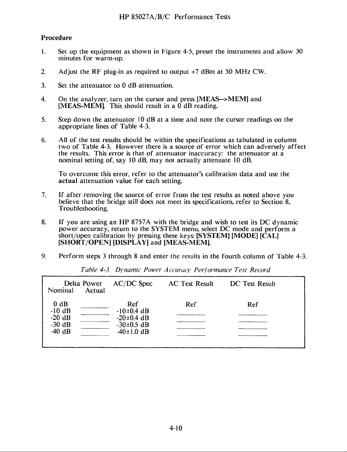
Procedure
1.
Set up
minutes
2.
Adjust
3.
Set
the
4.
On theanalyzer,
[MEAS-MEM].
5.
Step
appropriate
6.
All
of
two
of
the
results.
nominal
To
overcome
actual
the
equipment
for
warm-up.
the
RF
plug-inasrequired
attenuator
down
the
attenuator
linesofTable
the
test results should be
Table
4-3.
This
setting
of,
this
attenuation
HP
85027A/B/C
as
showninFigure
to0dB
turn
on
the
This
should
10
However
erroristhat
say
10
dB,
error,
value
refer
for
to
output
attenuation.
cursorand
resultina0dB
dBata time
4-3.
within
thereisa
of
attenuator
may
not
to
the
attenuator’s
each
setting.
Performance
4-5,
preset
Tests
the
instruments
+7 dBmat50
press [MEAS-->MEM]
reading.
and
note
the
cursor
the
specifications
source
of
error
astabulated
which
inaccuracy: the
actually
attenuate
calibration
MHz
CW.
and
readings
can
adversely
attenuatorat
10
dB.
data
and
and
in
allow
on
column
use
30
the
affect
a
the
7.
8.
9.
Nominal
0
-10dB
-20
-30
-40dB
If
after
believe
removing
that
the
the
bridge
source
still
does
Troubleshooting.
If
you
are
using
an
HP
8757A
power
short/open
accuracy,returnto
calibration
by
the
pressing
[SHORT/OPEN] [DISPLAY]
Perform
Delta
steps3through8and
Table
Power
4-3.
Dynamic
AC/DC
Power
Spec
Actual
dB
dB
dB
________
______
________
________
______
Ref Ref Ref
-10±0.4dB
-20±0.4
-30±0.5
dB
dB
-40±1.0dB
of
cr1-or
not
with
SYSTEM
these
and
[MEAS-MEM].
enter
Accuracy
from
meet
the
the
the
test resultsasnoted
its
specifications,
bridge
menu, select
keys:
resultsinthe
and
wishtotest
DC
[SYSTEM] [MODE] [CAL]
fourth
Performance
AC
Test
Result
______ ______
________ ________
________ ________
______ ______
refer
mode
Test
DC
to
its
and
column
Record
Test
Result
above
Section
DC
dynamic
perform
of
you
8,
Table
a
4-3.
4-10

HP
85027A/B/C
Adjustments
INTRODUCTION
You
do
not
have
normal
(Al)
match
85027
adjustments
ADJ
use.
However,
or
the
circuit
the
preamplifier
does
not
in
USTMENT
P05ZBLANK
to
make
if you
board
to
pass one
this section.
PROCEDURES
any
repair
assembly
the
characteristics
of
its
performance
SECTION
ADJ
USTMENTS
adjustments
oi-
replace
(A2),
you
to
the
the
must
of
the
tests you
5
HP
85027
internal
makethe
microcircuit.
may
for
bridge
following
need
to perform
regular
calibration
microcircuit
adjustments
Additionally,
P05ZBLANK
assembly
if
the
the
or
to
HP
Note:
to perform
adjustment
ONLY
REQUIRED
IFHP8350B
SERIAL PREFIX
2436ORBELOW.
HAS
the
potentiometers.
following
NOT
TERMINAT
Figure
adjustments
ED
BRIDGE
5-1.Adjustment
refer
to
5-1
Setup
Figure
5-2
for
the
locations
of
the

HP
85027A/B/C
Adjustments
AC
Adjustment Procedure
1.
Set
up
the
equipment
2.
3.
4.
power
locations
Connect the
Set
Preset
Adjust
the
meter
of
If
your
exactly
and
30dB
about
procedure
30.06
the
attenuator
the analyzer.
the
output
modulation.
Figure
and
the
adjustments.
power
attenuator
how
settings.
+13
referstocalibrated
dB.
5-2.
as
showninFigure
allow
dBmat50
forareading
30
meter
does not have calibration data,
much
for0dB.
Set
the
the
LocationsofA
minutes
sensortothe
attenuation
Determine
MHz
sourcetogenerate
of
for
NOTE
this
CW.
30
+6.5
djustment
5-1.
Turn
warm-up.
calibrated
changes
with
the
Use
this
dB;
for
50
dBm on
Potentiometers
on
the
Refer
10
dB step
between
source
figure
example,
MHz
the
power
analyzer,
to
Figure
attenuator.
determine
the
0dB
set
for
when
CW
29.9
meter
the
dB
without
source
5-2
for
or
modulation.
and
then
and
turn
on
5-2
5.
6.
7.
8.
9.
On
the
back
explains
be
Disconnect
the modulation
to
the
On the
On
Adjust
Set
ordered
attenuator.
HP
the
also
the
the
attenuator
the
as
the
8757A
HP
bridge’s
HP
85027A/B/C
of
the
bridgeisa
switch
configuration.
P/N85027-80004.)
powei-
frequency
8757A
sensor
Leave
or
8756A,
gain
for
30
must be
the
turn
potentiometer
dB.
printed,
from
test
turn
on
Adjust
Removethe
the
correct).
port
open.
on
the
the
smoothing
the
Adjustments
self-adhesive
label.
attenuator.
Connectthe
averaging
(5%,
(R5)
foracursor
bridge’s
plastic
Turn
(8,
defaultfactor).
load
label
(Note:
potentiometer
additional
on
the modulation
input
default
reading
withanote
port
of
factor)
of-6±0.1
(R29)
that
labels
the
and cursor.
may
(note:
bridge
dBm.
for
a
cursor
10.
Set
the
11.
Repeat
±0.1
DC Adjustment
12.
Set
13.
Set
dB/division.
14.
Turn
15.
Configure
16.
On
ground
reading
the
attenuator
cursor
steps8through
dB
and
This
analyzer.
the
HP
the
analyzer’s
off
the
bi-idge,
withashort
of
calibrated
to0dB
indicates-6±0.1
the
cursor
Procedure
DC
procedure
8757AtoDC
reference
the
RF
power
the
system by
temporarily
jumper.
-30 dB minus
and
i-eadjust
dBm.
10
until
the
with0dB
can
be
performed
mode.
level
from
the
pressing
short
6±0.1
the
change
attenuation
NOTE
to -50 dBmatmidscreen
source.
[CAL][CONFIG
pad
“Y”
(where
dBm.
gain
potentiometer
in levelisequal
indicates
only with an
SYSTEM]
the
yellow
(if
to
the
-6±0.ldBm.
HP
8757A
withascale
on the analyzer.
wire terminates)
required)
calibrated
of
until
5
30
to
dB
17.
Adjust
analyzer.
18.
Removethe
Feedthru
19.
Press
for
connected
20.
Adjust
possible.
effects
the
bridge
It should be
Null
Adjustment
[SYS] [CAL] [DC
the AUTOZERO
through
the
bridge
Work
of
your
Offset
short
completely.
“feedthru
slowlyasthe
adjustments.
potentiometer
less
Procedure
DET
feature
the
System
than
ZERO]
to
Interface.
null”
averaging
-50
(R25)
dBm.
[AUTOZERO] on the
function,the
potentiometer
5-3
foraminimum
analyzer
(RiO)
and
smoothing
I-eading
HP
8757A.
and
source
forasHIGHatrace
features
must be
will
on the
Note
mask
that
as
the

HP
85027A/B/C
Adjustments
NOTE
DC
Mode
21.
Turn
22.
Connectthe
23. Set
24.
Preset
output
25.
Disconnect
bridge
26.
On
factor)
27.
ONLY
potentiometer
28. Set
minus
reading.
Steps 19
noted.
RF
Adjustment
on
the
the
attenuator
the
source.
forareading
to
the
the
analyzem~,
and
if the
the
attenuator
6+-0.8dBm,
and
source
power
the
powei-
attenuator.
confirmthat
the
cursor
cursor
(R5)
20
must
Check
RF.
meter
for0dB.
Setitto
foracursor
for
adjustthe
sensortothe
of
+6.5
sensor
Leave
ai-e
does
not
30
dB.
generate
on.
be
rel)eated
dBm on
from
the
the
smoothing
indicate
reading
Only
bridge’s
until
calibrated
50
MHz
the
power
attenuatom~.
test
port
(5%,
-6±0.8
of
0±0.8
if the
cursor
load
potentiometer
no
further change
10
dB
step
CW
without
meter.
Connectthe
open.
defaultfactor),averaging
dBm,
adjustthe
dB.
does
modulation.
not
indicatecalibrated
(R29)
is
attenuatoi-.
input
bridge’s
for
that
Adjust
port
gain
cursor
(8,
of
the
default
-30
the
29. Set
the
30.
Repeat
calibrated
dB.
the
attenuator
cursor
indicates
steps
30
to0dB
-6±0.8
27
thi-ough30ONLY
dB
±0.8
dB
and
and
dBm.
readjust
the
cursor
until
the
gain
the
change
with0dB
potentiometer
in
levelisequal
attenuation
(if
required)
to
indicates
the
-6
until
dB±0.8
5-4
HP
85027A/B/C
Replaceable
Parts
INTRODUCTION
This
section
blies
available.
respond
abbreviations
placeable
replaceable
A2
Circuit
Figui-es
for
the3bridges.
6-2
shows
placeable
EXCHANGE
You
may
considerablecost
the
reference
and
theiim~ealize
by
the
contains
Table
to
the
manufacturers’
usedinthe replaceable
parts
lists
partsinreference
Board,
6-lA,
the
new
6-lB
thecomponent
parts.
ASSEMBLIES
replace,
termination.
HP
part
cost
savings.
assembly
information
6-2
for
common
and
The
circuit
on
an
saving.
numbers.
part
REPLACEABLE
for
lists
(1)
the
code
numbers
the
HP
85027A, 85027B
designator
to
all
three
6-iC
show
side,
exchange
This
Table
The
Thus, assemblies
number.
the major
board
Figure
assembly includes
assembly
basis,
6-i
defective
SECTION
ordering
names
parts
6-3 shows
lists
and
and
list.
order.
bridges.
assembly
the
bridge
these
assemblies must be
required
6
PARTS
parts.
addresses
(2)
Tables
and
Table
(A2)
the
the
factory
for
Table
reference
85027C
for
solder
microcircuit
input
spare
6-1
lists
of
manufacturers
dçsignatordefinitionsand
6-3A,
6-4
and
6-3B
respectively.
lists
thereplaceable
miscellaneous
all3bridgesisthe
side,
Table
and
test
repaired
returned
parts
the
exchange
and
6-3C
parts
same.
6-2
lists
assembly
port
and
stock must be
and
connectors
tested
for
assem
which
are
there-
They
list
pai-ts
locations
Figure
itsre-
realize
assemblies
credit
to
ordered
cor
the
of
and
-
-
a
REPLACEABLE
Organization
Table
Information
The
6-3isthe
a.
Electrical
designation.
b.
Major
c.
Options.
d.
Miscellaneous
following
a.
The
b.
Thepart
c.
The
the
assemblies
information
Hewlett-Packard
total
total
PARTS
listofreplaceable
assemblies
number
quantity
quantity
LIST
and
and
cables.
(including
is
part
check
(Qty)inthe
illustrated
tabulated
parts
their
components
mechanical
number.
digit
(CD).
instrument
therein.
andisorganized
in
alpha-numerical
and
attachinghardware)
for
each
entry:
or, if
as follows:
accompanied
oi-der
parts.
by
an
by
reference
illustration,
d.
The
description
of
the
part.
6-i
HP
e.
The
five
digit
code
of
f.
The
manufacturer’s
The
total
quantity
of
the
partinthe
ORDERING INFORMATION
To
orderapart
number
dress
the
(with
order
listedinthe
check
digittoensure
to
the
for
list.
nearest
part
each
Replaceable
85O27A/B/C Replaceable
the
typical
number
partisgiven only once,atthe
Hewlett-Packard
manufacturerofthe
for
the
part.
NOTE
Parts
List,
efficient
processing)
office.
indicate
Parts
and
part.
first
appearance
the
Hewlett-Packard
the
quantity
desired.
part
Ad
-
To orderapart
model
desired.
and
serial
Address
BRIDGE
HP
85027A
HP
85027B
HP
85027C
Table
Code
04713
06383
06665
24546
25088
27014
28480
32997
6-2.
thatisnot
number,
the order
Table
Manufacturers
Manufacturer
Motorola
PanduitCorp
Precision
Corning
Siemans
National
Hewlett-Packard
Bourns
listedinthe
the
to
6-1.
NEW PART EXCHANGE
NUMBER
5086-7376 5086-6376
5086-7377
5086-7399 5086-6399
MANUFACTURERS
SemiconductorProducts
Monoliths
Glass
Corp
Semiconductor
Inc
Trimpot
description
the
nearest
Exchange
Code
Inc
Works
Co
Corporate
Prod
(Bradford)
Replaceable
and
function
Hewlett-Packardoffice.
Microcircuit
List,
Reference
Corp
Div
Parts
of
BridgeAssemblies
PART
5086-6377
HQ
NUMBER
Designators
CODE LIST
Address
Phoenix
Tinley
SantaClara
Bradford
Iselin
SantaClara
Palo Alto
Riverside
List,
include
the
part
(REBUILT)
AZ
Park
PA
NJ
CA
CA
the
instrument
and
the
quantity
and A
IL 60477
CA
CA
bbreviations
Zip Code
85008
95050
16701
08830
95051
94304
92507
A
assembly
AT
termination
C
capacitor
CR
diode
J
jack
L
inductor
MP
miscellaneous
REFERENCE
assembly
part
DESIGNATORS
R resistor
TP
test
point
S
switch
U
integrated
YR
diode
W
cable
6-2
circuit

HP
85027A/B/C
Replaceable
ABBREVIATIONS
Parts
ADJ
ASSY
BD
CER
DBLHX
FXD
G
K
MA
MEG
MFR
MHZ
PF
PRCN
RGLTR
adjustable
assembly
board
ceramic
double
fixed
giga
1000
milli-amp
million (106)
manufacturer
megahertz
picofarad
precision
regulator
camfered,
(1O~)
hex
RMS
SGL
SI
SIG
SLDR
STR
TA
THD
TML
TRMR
TRN
UF
VDC
W
ZNR
root-mean-square
signal
silicon
signal
solder
straight
tantalum
thread
terminal
trimmer
turn
microfarad
volts,
direct
watt
zener
current
6-3
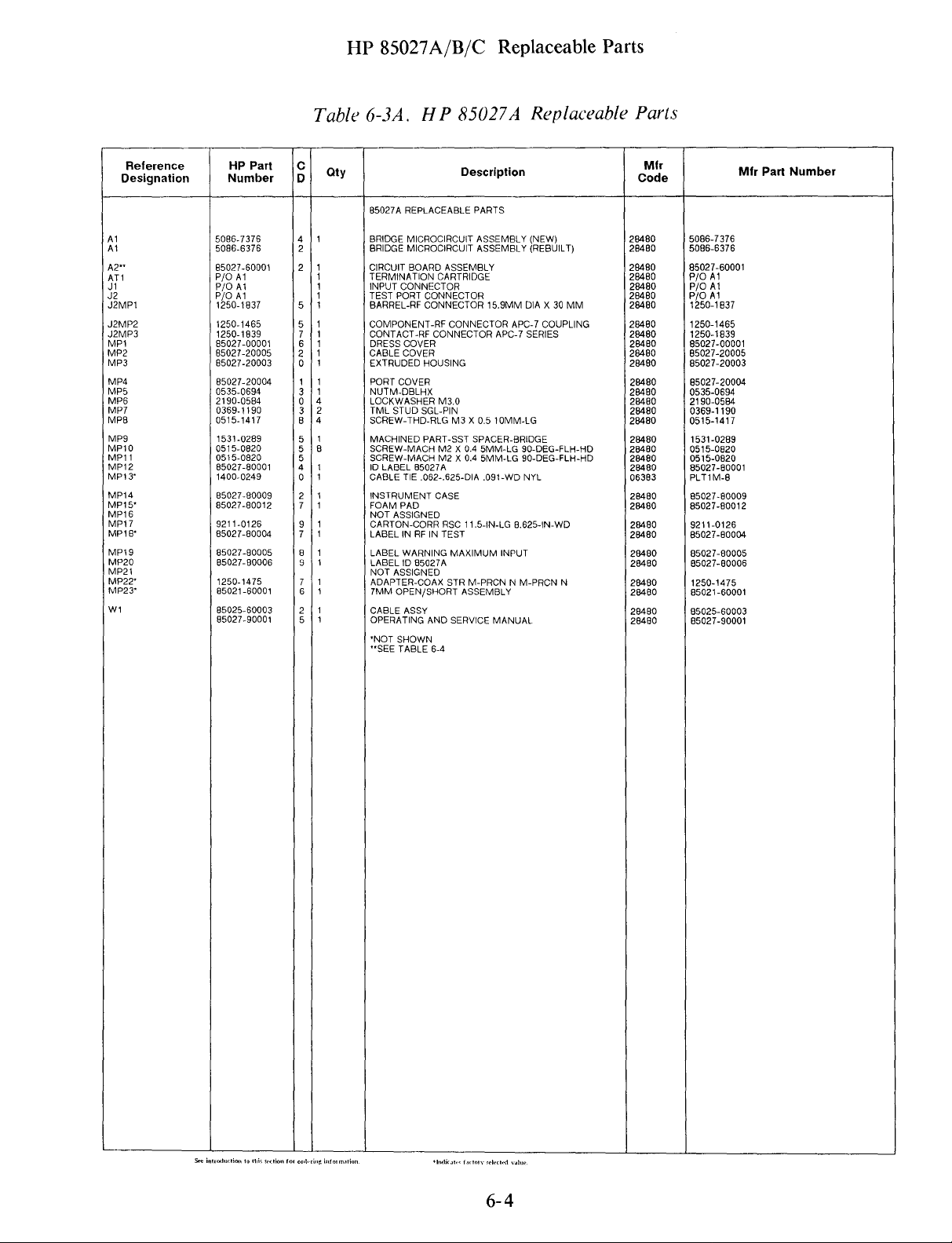
HP
85O27A/B/C
Replaceable
Parts
Reference
Designation
Al
Al
A2~~
AT
1
Jl
.12
J2MP1
J2MP2
J2MP3
MP
1
MP2
MP3
MP4
MP5
MP6
MP7
MPB
MP9
MP1O
MP1
1
MP12
MP13
MP14
MP15’
MP16
MP17
MP18~
MP19
MP2O
MP2
1
MP22
MP23~
Wi
HP
Part
Number
5086-7
376
5086-6376
85027-60001
P10
Al
P/0
Al
P/O
Al
1250-1837
1250-1465
1250-1839
85027-00001
8502
7-20005
85027-2000
85027-20004
0535-0694
2
190-0584
0359-1190
0515-14
17
1531-0289
051
5-0820
051
5-0820
85027-80001
1400-0249
85027-80009
85027-80012
9211-0126
8502
7-80004
85027-80005
85027-80006
1250-1475
85021
-80001
85025-6000
85027-90001
Table
C
D
4
2
2
5
5
6
2
0
3
3
0
4
3
2
4
B
5
8
5
5
4
0
2
7
9
7
8
9
7
6
2
3
5
6-3A.
Qty
85027A
BRIDGE
BRIDGE
CIRCUIT
TERMINATION
INPUT
TEST
BARREL-RF
COMPONENT-RF
CONTACT-RF
DRESS COVER
CABLE
EXTRUDED
PORT
NUTM-DBLHX
LOCKWASHER
TML
SCREW-THD-RLGM3X
MACHINEDPART-SST
SCREW-MACHM2X0.4
SCREW-MACHM2X0.4
ID
CABLE
INSTRUMENT
FOAM
NOT
CARTON-CORR
LABELINRFINTEST
LABEL WARNING
LABELID85027A
NOT
ADAPTER-COAX
7MM OPEN/SHORT
CABLE
OPERATING
~NOTSHOWN
~~SEE
HP
REPLACEABLE PARTS
MICROCIRCUIT
MICROCIRCUIT
BOARD
ASSEMBLY
CARTRIDGE
CONNECTOR
PORT
CONNECTOR
CONNECTOR
CONNECTOR
COVER
HOUSING
COVER
M3.0
STUD
SGL-PIN
LABEL 85027A
TIE
.062-.625-DIA .091-WD
CASE
PAD
ASSIGNED
ASSIGNED
ASSY
TABLE
RSC11.5-IN-LG
AND
6-4
85027A
Description
ASSEMBLY
ASSEMBLY (REBUILT)
15.9MM
CONNECTOR
MAXIMUM
STIR
ASSEMBLY
SERVICE
APC-7 COUPLING
APC-7
0.5
1OMM-LG
SPACER-BRIDGE
5MM-LG
5MM-LG 90-DEG-FLH-HD
8.625-IN-WD
INPUT
M-PRCNNM-PRCN
MANUAL
Replaceable
(NEW)
DIAX30
MM
SERIES
90-DEG-FLH-HD
NYL
N
Parts
Mir
Code
28480
28480
29480
28480
28480
28480
28480
28480
28480
28480
28480
28480
28480
28460
28480
28480
28480
28480
26480
28480
28480
05383
28480
28480
28480
28480
28480
28480
28450
28480
28480
28480
5086-7
376
5085-6376
85027-6000
P/O
Al
P/O
Al
P/0
Al
1250-1837
1250-1465
1250-1839
85027-00001
85027-20005
85027-20003
85027-20004
0535-0694
2190-0564
0369-1190
0515-1417
1531-0289
0515-0820
0515-0820
85027-80001
PLT1
M-8
85027-80009
85027-80012
9211-0125
85027-80004
85027-80005
85027-80006
1250-1475
85021
-60001
85025-60003
85027-9000
Mfr
1
1
Part
Number
S..lnI~
(!(~(I,.,,t.II)ku.cIi.,.
6-4

MP3
MP2O
(NOT
VISIBLE)
HP
85027A/B/C
Replaceable
Parts
Ji
Al
MP2
MP5~/
MP19
(NOT
VISIBLE)
MP1
MP18
(REMOVED
TO
SHOW
INTERIOR)
~~~—~--—---
MP6
(FOUR
(NOT
TIMES)
VISIBLE)
J2MP1
J2MP3
MP1O
MP9
(FOUR
(NOT
(NOT
VISIBLE)
TIMES)
VISIBLE)
Only
the
parts listed are replaceable. Any
any
disassembly
Section8of
nectors
can
Figure
this
be
6-lA.
or
repair
manual
repaired
HP
CAUTION
procedure
will
or
replaced
85027A
not
void
the
warranty.
only
Replaceable
6-5
attempttoperform
specifically
outlined
Damaged
by
Hewlett-Packard.
Parts
Identification
in
con
-

HP
85027A/B/C
Replaceable
Parts
Reference
Designation
Al
Al
A2”
AT1
J1
J2
MP1
MP2
MP3
MP4
MP5
MP6~
MP7
MP8
MP9
MP1O
MP1
1
MP12~
MP1
3~
MP14
MP15
MP15
MPi7~
MP18
MP19
MP2O
MP21~
MP22~
MP23~
Wi
HP
Part
Number
5086-7377
5088-0377
85027-6000
P/O
Al
P/0
Al
P/0
Al
85027-00001
85027-20005
85027-20003
85027-20004
0535-0694
85027-00002
0360-0002
051
5-1445
1531-0289
051
5-0820
0515-0912
8502
7-80002
55027-80012
85027-80010
2190-0584
85027-80007
9211-0126
8502
7-80004
85027-80005
85027-60002
85027-6000
85037-60001
85025-50003
85027-9000
Table
C
D
5
3
1
2
6
2
0
3
7
6
2
4
5
5
4
6
4
5
7
5
0
4
0
9
7
8
3
3
4
4
2
1
5
6-3B.
oty
85027B
BRIDGE
BRIDGE
CIRCUIT
TERMINATION
INPUT
TEST
DRESS COVER
CABLE COVER
EXTRUDED
PORT
NUTM-DBLHX
WRENCH,
TERMINAL-SLDR
SCREW-THD-RLGM3X
MACHINEDPART-SST
SCREW-MACH M2X0.4
SCREW-MACH
ID
FOAM
INSTRUMENT
LOCK
LABELID85027B
CARTON-CORRRSC
LABELINRFINTEST
LABEL WARNING
NOT
ADAPTER
ADAPTERM3,5F3.5
3.5MM
CABLE
OPERATING
HP
REPLACEABLE
MICROCIRCUIT
MICROCIRCUIT
BOARD
CONNECTOR
PORT
CONNECTOR
HOUSING
COVER
CONNECTOR-SAVER
LABEL 85027B
PAD
WASHER
ASSIGNED
M 3.5M3.5
OPEN/SHORT
ASSY
AND
85027B
Description
PARTS
ASSEMBLY
ASSEMBLY
ASSEMBLY
CARTRIDGE
LUG
PL-MTG
0.5
SPACER-BRIDGE
5MM-LG 90-DEG-FLH-HD
3.0X8MM
CASE
PN PD
M3.0
ll.5-IN-LG
MAXIMUM
ASSEMBLY
SERVICE
Replaceable
(NEW)
(REBUILT)
FOR-#2-SCR
8MM-LG
8.625-IN-WD
INPUT
MANUAL
Parts
Mir
Code
28480
28480
28480
28480
28480
28480
28480
28480
28480
28480
28480
28480
28480
28480
28480
28480
28480
28480
28480
28480
28480
28480
28480
28480
28480
28480
28480
28480
28480
26480
5086-7377
5086-6
377
85027-60001
P/D
Al
P/O
Al
PlO
Al
85027-00001
85027-20005
85027-20003
8502
7-20004
0535-0694
85027-00002
0360-0002
0515-1445
1531-0289
0515-0820
0515-0912
85027-80002
85027-80012
85027-80010
2190-0584
8502
7-80007
9211-0126
85027-80004
85027-80005
85027-60002
85027-60003
85037-60001
85025-60003
85027-90001
Mfr
Part
Number
NOT SHOWN
~~SEE
TABLE
6-4
6-6

HP
85027A/B/C
Replaceable
Pai-ts
Al
MP9
(NOT
()
VISIBLE)
M18
(NOT
VISIBLE)
BACK SIDE
—.---------_
(FOUR
TIMES)
MP1
(NOT
VISIBLE,ONSIDE)
-~
9
J2
M4
A2
MP8
(NOT
(FOUR
TIMES)
VISIBLE)
Only
any
Section8of
nectors can
the
parts
disassemblyorrepair
this
be
Figure 6-lB.
CAUTION
listed
are replaceable. Any
procedure
mnanual
will
void
not
the
repairedorreplaced only
HP
85027B
Replaceable
6-7
attempt
specifically
warranty.
by
Hewlett-Packard.
Parts
Identification
to
perform
outlined
Damaged
in
con
-

HP
85027A/B/C
Replaceable
Parts
Reference
Designation
Al
Al
A2”
AT1
.11
J2
MP1
MP2
MP3
MP4
MP5
MP6
MP7
MP8
MP9
MP1O
MP1
1
MP1
2
MP13
MPl4~
MPl5~
MP16
MP17
MP18
MP19
MP2O
MP2l~
MP22~
MP23~
Wl
HP
Part
Number
5086-7399
5086-6399
85027-60001
P/O
Al
P/O
Al
P/O
Al
85027-00001
85027-20005
85027-20003
85027-20004
0535-0694
0515-1417
1531-0289
0515-0820
0515-0912
85027-80003
1400-0249
9211-4429
85027-80012
85027-80008
85027-80011
8502
7-80004
85027-80005
2190-0584
1250-1475
1
1512A
85032-60001
85025-60003
85027-90001
Table
C
D
9
2
6
2
0
3
8
4
5
5
4
6
4
6
0
3
7
6
7
8
0
4
0
9
2
5
6-3C.
Qt~/
650270
BRIDGE
BRIDGE
CIRCUIT
TERMINATION
INPUT
TEST
DRESS
CABLE
EXTRUDED
PORT
NUTM-DBLHX
NOT
ASSIGNED
NOT
ASSIGNED
SCREW-THD-RLG M3X0.5
MACHINED PART-SST
SCREW-MACH M2X0.4
SCREW-MACH 3.0X8MM
ID
LABEL
CABLE
CASE-ACCESS
FOAM PAD
LABELID85027C
INSTRUMENT
LABELINRFINTEST
LABEL WARNING
LOCKWASHERM3.0
ADAPTER-COAX
SHORT”N’
OPEN
CABLE
OPERATING
NOT SHOWN
~~SEE
HP
85027C Replaceable
Description
REPLACEABLE
MICROCIRCUIT
MICROCIRCUIT
BOARD
CONNECTOR
PORT
CONNECTOR
COVER
COVER
HOUSING
COVER
85027C
TIE
.062-.625-DIA .091-WD NYL
MALE
CKT
ASSYMN
ASSEMBLY
TABLE
ASSEMBLY
CARTRIDGE
BIRCH
CASE
MAXIMUM
STIR
AND
SERVICE
6-4
PARTS
ASSEMBLY
ASSEMBLY (REBUILT)
SPACER-BRIDGE
5MM-LG
9.71IN-LG 6.76IN-WD
M-PRCNNM-PRCN
1OMM-LG
PN PD
INPUT
MANUAL
(NEW)
90-DEG-FLH-HD
N
Paris
Mfr
Code
28480
26480
28480
28480
28480
28480
28480
28480
28480
28480
28480
28480
28480
28480
28480
28480
06383
28460
28480
28480
28480
28480
28480
26480
28460
28480
28480
28480
28480
5086-7
399
5086-6399
85027-60001
P/O
Al
P/O
Al
P/O
Al
85027-00001
85027-20005
8502
7-20003
85027-20004
0535-0694
051
5-1417
1531
-0289
0515-0820
0515-0912
85027-80003
PLT1M-8
9211-4429
65027-80012
85027-80008
85027-80011
85027-80004
85027-80005
21
90-0564
1250-1475
1
l5l2A
85032-60001
85025-60003
85027-90001
Mfr
Part
Number
S.t
~
t~I
~
6-8

Ml8
(NOT
VISIBLE)
BACK SIDE
HP
85027A/B/C
Replaceable
Parts
Al
MP9
(NOT
MP1O
VISIBLE)
(NOT
VISIBLE)
M4
(NOT
VISIBLE)
Only
the
parts
listed are replaceable. Any
any disassemblyorrepair
Section8of
nectors can
this
manual
be
repairedorreplaced
M19,ONSIDE
CAUTION
procedure
will
void
attempt
not
specifically
the
warranty. Damaged
only
by
Hewlett-Packard.
to
perform
outlined
in
con
-
M8
(FOUR
(NOT
VISIBLE)
TIMES)
Figure 6-iC.
HP
85027CReplaceable
6-9
Parts
Identification

HP
85027A/B/C
Replaceable
Parts
Reference
Designation
A2
A2C
1
A2C2
A2C3
A2C4
A2C5
A2C6
A2C7
A2C8
A2C9
A2C1
0
A2C1
I
A2C12
A2CR1
A2CR2
A2CR3
A2MP1
A2R
1
A2R2
A2R3
A2R4
A2R5
A2RE
A2R7
A2RB
A2F1S
A2R1
0
A2R1
1
A2R12
A2P14
A2R15
A2R16
A2R17
A2R18
A2R1
9
A2R21
A2R22
A2R23
A2024
A2R25
A2R28
A2R29
A2R30
A2RT1
A2S
1
A2U
1
A2U2
A2U3
A2U4
A2U5
A2U6
A2VR1
A2VR2
HP
Part
NumberC0
85027-60001
0160-5375
0160-5375
0160-5375
0160-5375
0180-2683
0160-5375
0160-5375
0160-5375
0160-5375
0180-2661
0180-2661
0160-0573
1901-0050
190
1-0050
1901-0539
85027-20001
0698-72
12
0698-
7279
0698-
724
9
0698-
7294
2100-3091
0698-7212
0698-
7212
0698-7212
0698-8615
2100-3097
0698-72
12
0688-72
12
0698-7268
0698-7236
0698-
725
3
0698-7212
0698-7229
0698-
724
7
0698-
726
1
0698-7253
0698-7251
0698-7251
2100-3091
0698-
7224
2100-3266
0698-
7277
083
7-0324
3101-2851
1
NB7-8045
1
NB7-8039
1826-04
12
1826-0772
1826-0285
1826-0932
1902-3246
1902-3245
Table
0tY
2
8
2
2
2
2
2
2
2
2
5
5
2
2
3
3
3
8
9
7
8
2
2
9
9
9
8
9
9
9
2
8
9
8
0
8
B
2
6
6
3
6
6
6
2
6
8
6
6
0
2
6
6
6-4. A2Bridge
Circuit
Description
A2
BRIDGE
CIRCUIT
BOARD
ASSEMBLY
BRIDGEPCBOARD
CAPACITOR-FXD
CAPACITOR-FXO
CAPACITOR-FXD
CAPACITOR-FXD
CAPACITOR-FXD
CAPACITOR-FXD
CAPACITOR-FXD
CAPACITOR-FXD
CAPACITOR-FXD
CAPACITOR-FXD
CAPACITOR-FXD
CAPACITOR-FXD
DIODE-SWITCHING
DIODE-SWITCHING
DIODE-SM
BD-AC/DC
RESISTOR
RESISTOR 61.9K
RESISTOR 3.48K
RESISTOR
RESISTOR-TRMR2K10%CTOP-ADJ17-TRN
RESISTOR
RESISTOR
RESISTOR
RESISTOR
RESISTOR-TRMR
RESISTOR
RESISTOR
RESISTOR
RESISTOR
RESISTOR
RESISTOR
RESISTOR
RESISTOR
RESISTOR
RESISTOR
RESISTOR
RESISTOR
RESISTOR-TRMR2Kl0°/~CTOP-ADJ
RESISTOR
RESISTOR-TRMR
RESISTOR
THERMISTOR
SWITCH
PREAMP
CLOCK HYBRID
IC
COMPARATOR
ICVRGLTR-ADJ-POS
ICVRGLTR
ICOPAMP
DIODE-ZNR21.5V
DIODE-ZNR21.5V
ASSEMBLY
.1UF
*-l0°/o
.1UF
.1UF
.1UF
4.7UF-s-20°/o
.1UF
.1UF
.1UF
.IUF
lUF~-10%
1UF+-10%
4700PF
SIG
SCHOTTKY
BRIDGE
100
l0/o
I0/o
l0/o
lOOK
1°/o
1001%.05WFTCO*-100
100
lOb
1001%.05WFTCO+-lOO
75K
iSo
100K
1001%.05W
100
l°/o
147K1%.05WFTCO*-100
1K
10/s
.05WFTCO÷-100
5.11K
lOb
100
10/o
511l%.05WFTC—0+-l00
2.97K
10/s
11K
l°/o
5.11K
l°/o
4.22K 1%
4.22K 1°/s
316
1°/o
10K
51.1K
l°/~
DISC
HYBRID
ASSEMBLY
ASSEMBLY
PRCN
TO-92
PRCN
8-DIP-C
5°/o
5°/o
50V0C
*-lO%
5OVDC
*-lO%
50VDC
+-l0%
5OVDC
35VDC
o--l0°/o
5OVDC
+-l0°/o
5OVDC
c~1E%
5OVDC
*-10%
5OVDC
5OVDC
5OVDC
+-20%1O0VDC
80V 200MA 2NS DO-35
80V 200MA 2NS
.05WFTC—0+-100
.05WFTCOc-l00
.05WFTCO-s-l00
.05WFTCO’s-lOO
.05WFTCO+-lOO
.05WFTC.0+-100
10°/.C
TOP-ADJ17-TRN
F TC.O’i’-lOO
.05WFTCO+-lOO
.05WFTC—0*-100
.05WFTC—Oo’-lOO
.05WFTCO+-l00
.05WFTC~0+-l00
.05WFTC-0.-l00
.05WFTC—0+-l00
.05WFTCO*-100
.05WFTC.0*-100
10°/aC TOP-ADJ
.05WFTC—0.-lO0
2K-OHM
TC--4.4%/C-DEG
DUAL
8-DIP-P
l.2/32V
TO-92
PKG
00-35
P0-4W
00-35
PD-.4W
Board
CER
CER
CER
CER
TA
CER
CER
CER
COP
TA
TA
00-35
17-TON
17-TRN
PKG
PKG
CER
A ssembli’
Mfr
Code
28480
28480
28480
28480
28480
28480
29480
28480
28480
28480
25088
25088
28480
28480
28480
28480
28480
24546
24546
24546
24546
32997
24546
24546
24546
28480
32997
24546
24546
24546
24546
24546
24546
24546
24546
24546
24546
24546
24546
32997
24546
32997
24546
28480
28480
28480
28480
27014
28480
04713
06665
28480
28480
Mfr
85027-60001
0160-5375
0160-5375
0160-5375
0160-5375
0180-2663
0160-5375
0160-5375
0160-5375
0160-5375
Dl
ROGS1
A5OK
Dl
ROGS1
A5OK
0160-0573
1901-0050
1901-0050
1901-0539
85027-2000
C3-1/8-TO-100R-F
C3-1/8-T0-6
C3-1/8-T0-3481-F
C3-l/8-T0-1
3292W-1-202
C3-l/6-TO-100R-F
C3-l/8-TO_
C3-1/B-TO-100R-F
0698-86
3292W-1-104
C3-1/8-TO-100R-F
C3-l/8-TO-100R-F
03-1/8-TO03-1 /8-TO-
C3-1/8_T0-5111F
C3-l/8_TO-100R_F
C3-1
C3-l/6C3-1/8_T0-l
C3-1/8-TO-51
C3-1/8-T0-4221-F
C3-1
3292W-l
C3-1/8-TO-316RF
3292W-1-l03
C3-1/8-TO-5l
083
3101-2851
1
1
LM393N
1826-0772
MC79LO5C
OP-27FZ
1902-3245
1902-3245
15
/8-TO-511R-F
10-2871-F
/8-T0-4221
7-0
324
NB7-8045
N67-8039
-202
1
192-F
003-F
100R-F
1473-F
1001-F
102-F
11-F
12-F
Part
-F
Number
So,’
1~1<1oIslis,,
sin.
n<lis<<
iS! S
6-10
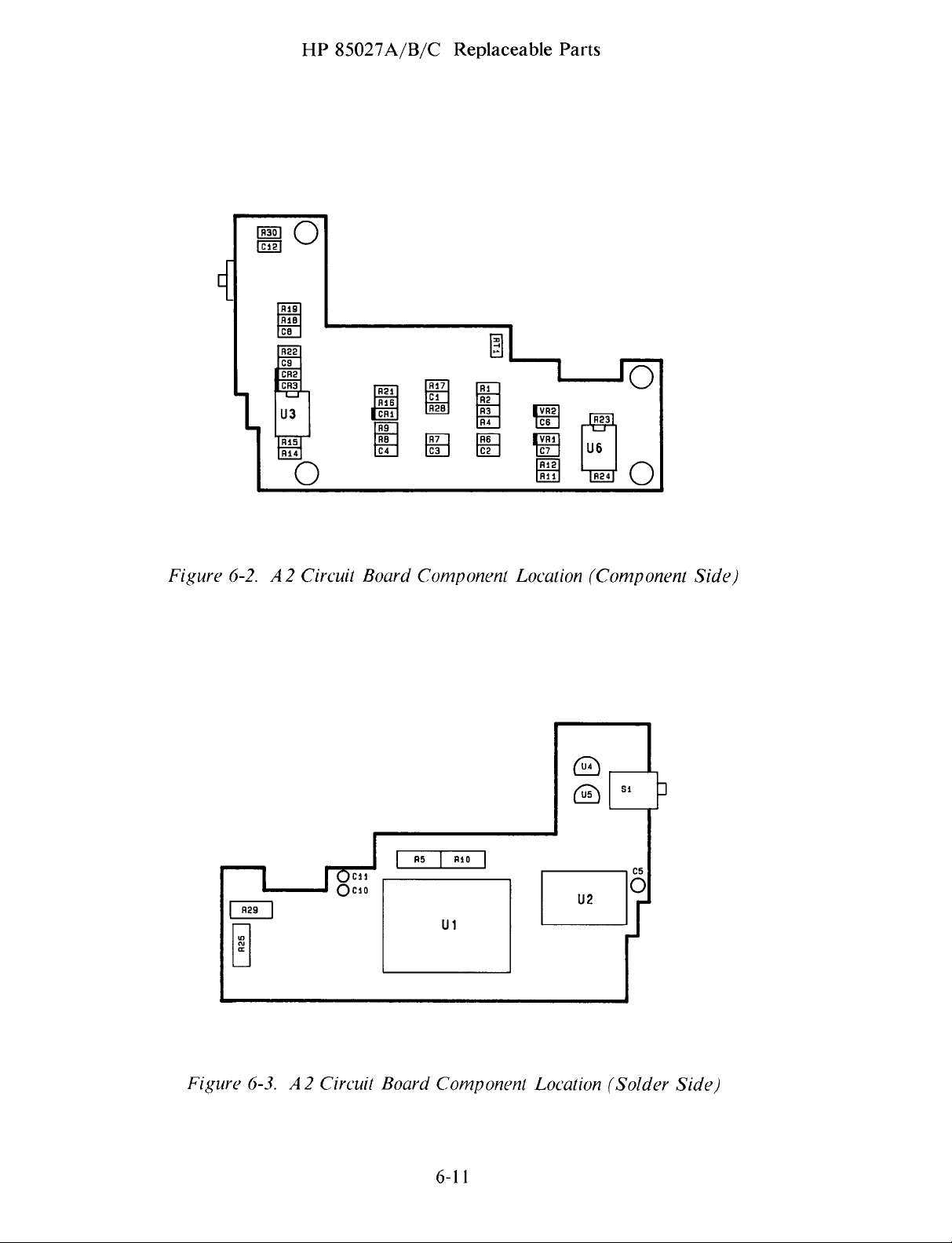
HP
85027A/B/C
Replaceable
Parts
Figure
6-2.A2
Circuit
Board
Component
Location
(Component
Side)
Figure
6-3.
A2Circuit Board
Component
6-il
Location
(Solder
Side)

HP
85027A/B/C Manual
BackdatingChanges
INTRODUCTION
By
following
withaserial
APPLICATION
This manual
There
To adapt
a
part
Additional
INSTRUMENTS
are
Manual
number
the
number
applies
no
earlier
this
manualtoa
Changes Supplement.
(on
information
MANUAL
instructions
prefix
directly
versions
the
title
page)
about
COVERED
on this page,
lower
later
or
to
instruments
of
the
version
The
andisavailable
serial
BY
THE
SECTION
BACKDATING
you
higher
instrument (with
(higher
supplementiskeyed
number
MANUAL.
7
canadapt
than
the
with
serial
serial
free
coverageisin
CHANGES
this
manual
one
on
the
number
lower
number
from Hewlett-Packard.
prefixes
serial
prefix)
to this
Section1under
to
title
..page.
number
instrument,
manual’s
on
any
instrument
the
title
prefixes).
print
refer
date
page.
to
and
7-1

HP 85027A/B/C
Service
INTRODUCTION
You
will
findinthis
HP
the
85027.
Theory
Heed
of
Troubleshooting
the
Performance
refer
to
Adjustments
Procedures
laterinthis section.
Operation
the
the
Tests
section
caution
with
bridge
(Section
in Section
information
signsorrisk
its
begins
4).
5.
Those
whichislistedinSection1,General
You
will also
find
the
following
section:
*
Gaining
*
Cable
Power
*
Input
Internal
Access
ContinuityCheck
Cable
Port
Replacement
and
Test
Port
SECTION
SERVICE
concerning
associated
with
performing
If
the
If
the problem
procedures
Information.
inspection,
Resistance
damaging
diagrams
bridge
does
repair
Checks
8
troubleshooting
the
bridge.
as
an
aidtotroubleshooting.
the
Operator’s
not pass
persists,
require
refer
the
use
and replacement
and
You
may
Check
the
Performance
to
Troubleshooting
of
test
procedures
repair
of
the
wishtoread
(Section3)and
Tests,
equipment
in this
*
A2
*
Microcircuit
Al
*
Power
* Signal
*
Clock/Control
*
Connector
*
HP
THEORY
The
HP
85027
squarewave
modes,
and
In
(envelop
display.
AC
mode,
the
detects)
peak-to-peak
Since
only
extraneous
drift-free
Circuit
Bridge
Supply Check
Path
85027A
OF
OPERATION
can
modulated
bridge
the
signalisamplitudemodulated
this signal to
voltage
the
modulated
signals
operation
Board
Assembly
Replacement
Check
Microcircuit
Assembly
Check
Check
Inspection
APC-7
detect
providesa27.8
Connector
RF
(AC
or
mode)
microwave
or
kHz
producea27.8
corresponds
to
the
signalisdetected,
are
disregarded. Additionally,
Replacement
Repair
signals
unmodulated
square
wave
at
kHz
magnitude
unmodulated
which
(DC
signal
the
square
of
this
are
mode).
for
source.
wave
the
signalatthe
broadband
technique
either
In
the
analyzer
The
bridge
signal
provides
27.8
both
detection
whose
bridge test
noise
nearly
kHz
to
interpret
demodulates
port.
and
8-i

HP
85027A/B/C
In
DC
mode,
into
an
equivalentDC
it
amplifies
outputs
some
amplifiers
TROUBLESHOOTING PROCEDURES
the
source
the chopped
this signaltothe analyzer.
with
signalisnot
voltage
signaltosimulate
ALC
whichitthen
circuits
modulated.
This
and
Service
Instead
chopsata
the
signal
techniqueispreferrable
very
narrow
the
frequency
produced
bandwidth
bridge
by
for
filters.
convertsthe
of
27.8
kHz.
AC
detection
devicessuch
signal
Finally
and
as
Ifaproblem
Performance
Gaining
To
I.
2.
3.
4.
Internal
obtain
Disconnect
With
coupling
Removethe
Removethe
persists
Tests in Section4,perform
The
sensitivetoelectrostatic
station
wrist
with
the
grounded
accesstothe
the
HP
nut
after
HP
85027
equipped
strap.
your
leadsofthe
Access
the
two
Do
fingers.
instrument
interior
bridge
85027A
from
the
screws which
port
cover.
you
have
contains
with
not
Before
digital
of
from
only, use a
APC-7 test
performed
the
CAUTION
microcircuits
discharge (ESD).
an
anti-static
touch
the
center
you
multimeter
chassis.
the
HP
theanalyzer.
thin
port
hold
the
the
Operator’s
troubleshooting
which
surface.
contacts
make
85027,
a measurement,
by
touching
proceed
1/2
inch
connector.
(test)
portcover
open-end
CheckinSection3or
procedures
are
highly
Work
onlyata
Wearagrounded
of
the
connectors
ground
them to
as
follows:
wrench
(end
the
to
plate).
outlined
remove
the
below.
the
5.
Cable
1.
2.
3.
Slide
the
circuit
Continuity
Disconnect
touching
Use a
power
bridge
If
Power
board
digital
cable
housing.
there
Cable
top
dress
and
Check
the
them
multimeter
(WI) from
are
any
Replacement.
cover
the
HP
to
the
Table
discontinuities,replace
bridge
85027
grounded
(DMM)
the
8-1
out
of
assembly
from
connector
lists
the
the
chassis
to
the
bridge
are
analyzer
of
checkthe
pinstothe
Wi
connector
cable
8-2
housing.
now
and
the
DMM.
continuity
Wi
The
component
accessible.
ground
wire connections
pins
by
the
of
and
the corresponding
following
leads
the
conductors
the
side
of
of
the
DMM
inside
the
instructions
the
of
wires.
by
the
in

HP 85027A/B/C
Service
Power
1.
2.
3.
4.
5.
Cable
To
Replacemnent
replace
instructions
Unsolderthe
Removethe
Removethe
Replacethe
Note
that
the
Table
8-I.
Table
8-1.
Connector Pin
the
power
above
wires
two
cable (WI),
in
“Gaining
connected
screws
1/2 inch hex nut
cable
pads
and
on
reinstall
which
ConductorsinPower
I
2
3
4
5
first
open
from
Internal
to
the
the
Access”.
power
cable
which fastens
it by
performing
the
wires
are
Conductor
White
Green
Yellow
Blue
Red(R)
the
bridge
cable/circuit
cover
end
the
cabletothe
in
soldered
Cable
Wi
(Label) Signal
(W)
(0)
(Y)
(B)
Output
Return
Control
-12.6v
+15v
by
following
board
assembly.
plate.
end
plate.
reverse
are
order
labeled
steps1through
as
indicated
the
4.
in
Input
1.
Port
and
Disconnect
DMM
by
Test
the
touching
WORK STATIC-FREE.
microcircuitsinthe
2.
Measurethe
3.
4.
5.
center
Measurethe
ground
resistance
Measurethe
ground.
If
defective
any
contact
(the
should be
It
should
of
the above
and
black/white
Replacement.
MicrocircuitCheck
Port
Resistance
HP
85027
them
resistance
of
test
resistance
83±2
resistance
be
must be
from
port
from
wire
from
83±2
results
replaced:
from
to
its
grounded
HP
85027
the
connector
the
connected
ohms.
the
ohms.
are
Checks
the
analyzer. Momentarily
chassis.
CAUTION
ESD
can
damage
bridges.
center
center
center
not
refer
contact
J2.
contact
to
contact
correct,
to “Al
The
the
the
of
resistance
of
microcircuit
of
bridge
Bridge
the
highly
input
port
should
input
connector
test
port
microcircuit
Microcircuit
ground
sensitive
connector
be
33±2
housing).
connector
Assembly
the
leads
Ji
ohms.
Ji
to
signal
The
J2
to
assembly
of
to
signal
Al
the
the
is
1.
Connect
the
synthesized
input
sweeper.
port
of
the
Do
not terminate
bridgetothe
the
8-3
RF
out
bridge
port
test
of
port.
the
RF
plug-in
or

2.
3.
4.
5.
A2
1.
2.
3.
Set
the
Withatrue
microcircuit.
The
bridge
0.07
Vm.ms.
If
the
reading
which
see
Figure
defective
Circuit
To
cable wires
At
wires
Removethe
Board
remove
the
from
RF
output
RMS
diodeisprobably
in
explains
circuit
the
5-2).
and
must be
Assembly
the
circuit board,
(see
board
the
microcircuit.
four
Measure
“Gaining
to
+13 dBm
DMM,
step3is
switch
replaced.
Replacement
pads,
screws
HP 85027A/B/C
with
the
measure
low,
configuration
again.
Internal
unsolder
and
the
voltage
good if
remove
first
lockwashers which
the
If
the
open
Access”
the
Service
modulation
across
reading
the
self-adhesive plastic
and center
reading
up
the
and
signal, signal
in
the
remains
bridge
“Power
fastenthe
on.
step3is
ground
the
and
Cable
two
output
approximately
load
potentiometer
low,
the
unsolder
Replacement”).
and
A2
pins
label
with
microcircuit
the
chassis
circuit
board
of
the
(R29,
power
ground
the
note
is
to
the
4.
5.
6.
Al
1.
2.
3.
4.
5.
standoffs.
Reverse
Referto
board
Reassembly
Bridge
Type
newor
On
connector
Removethe
port
Removethe
cable
Unsolderthe
white/red
microcircuit
to
Microcircuit
the
the
cover.
and
the
above
Section5,Adjustments,
the
Al
the
serial
replacement
HP
85027A only,
withathin
two
two
cable
wire
pins.
procedure
microcircuit.
remaining
Assembly
number
bridge
1/2 inch
screws holding
screws holding
cover
two
(signal)atthe
to
white/black
parts
of
remove
move
to
install
and
of
the
Replacement
the
HP
85027
assembly.
the
open-end
the
the
freely.
wires
microcircuit.
the repaired
perform
bridge.
on
coupling
wrench.
(test)
port
cable
(signal
cover
ground
Removethe
or
replacementboard.
them
as
indicated
the
rear
panel
nut
from
cover
(end
(end plate). This will
and
label
the
APC-7
plate)
chassis
capacitor
to
match
suppliedwith
test
port
and
remove
allowthe
ground)
from
and
the
the
A2
the
the
the
6.
7.
Removethe
Assemblytothe
Removethe
extruded
four
A2
housing.
screws
standoffs.
Circuit Board
and
lockwashers
Assembly
8-4
which
with
fastenthe
the
cable
cover
A2
Circuit Board
and
cable
from
the

8.
9.
10.
11.
12.
Turn
the
bridge
assembly.
under
Install
the
Perform
Referto
it.
the
spacer.
in
Section5,Adjustments,
microcircuit
Attach
the
over.
Take
out
spacerover
Reinstall
reverse
to
new
sequence
the
preamplifierand
labeltothe
HP
Removethe
the
microcircuit
the screw
the
four
bridge
85027A/B/C
four
screws which
assembly.
holes
and
microcircuit
steps2through
and
perform
pass
the
housing.
Service
fastenthe
Note
the
the
bridgemicrocircuit
assembly
screws.
8.
them
as
required
performance
microcircuit
stainless steel
assembly
to
match
tests.
spacer
over
the
Power
1.
2.
Supply
Connectthe
Check
powercord
analyzer.
Refer
to
Figure
voltsatthe4pads
analyzer,
+8.3±0.3V;
those
-5V
5V
voltages
should
8-i
and
indicated.
of
the
checkthe
Since
are
specifiedinthe
be
-5±0.2V.
bridge
power
the
(Wi)
supply
+1SV
to
the
analyzer
voltages
and
-12.6V
analyzer’s
of
are
manual.
and
turn
+15,
supplied
The
on
the
-12.6,+8and
by
the
+8V
should
-5
be
3.
Referto
indicated
Figure
Figure
by
malfunction.
8-1.A2
8-1
and
Circuit
checkthe
Board Power
power
suppliesatthe
8-5
Supply
Check
various
Points
components
as

HP
85027A/B/C
Service
Signal
1.
2.
Clock/Control
1.
2.
3.
4.
5.
CONNECTOR
Path
Check
Check
as
Check
voltage
With
thereisno
Set
Configure
Verifyasquarewave
If
27.778
U2 pin
that
the
U!
the
measured
the
the
pin
kHz
output
output
should be
Check
HP
85027
squarewave
HP
85027
the
HP
14
does
at
U!
4.
INSPECTION
of
the
buffer
in
step3of
of
Ui
pin
approximately
configuration
output
configuration
8757A
not
pins2and3,also U2 pins1and2;55.555
for
output
haveasquarewave
amp
the
microcircuit
14
with
O.
at
U2
switch
DC
of
27.778
at
the
44Vrms.
switch
pins1,2
mode.
U6 pin
gain
setat[HP8756/HP8755],
to
kHz
6.
The
check.
potentiometer
and
the
[HP8757] position.
at
UI
output,
It
4.
pin
check
voltage
may
14.
should be
be
offset.
(R5)
centered.
verifythat
forasquarewave
kHz
at
U!
the
same
The
of
pin9,also
Periodically
damageagood
bridges
connector
it.
Visual Inspection
Inspect
crucial,
lighting, casts
expose.
They
Examine
contamination
scratches,
see
Ifaconnectorisdirty,
suggestions.
Try
from
cleaning
the
are
with
blowing
the
thin
inspect
with
damagedconnectors
fails
connectors
theexact
shadows.
Magnifying
readily
connectors
rounded
the
magnifying
Note
off
surface
solventifneed
metal
theconnectors
connector
the
visualormechanical
with
powerisnot.
available
or
corrosion.
shoulders
that
the
carefully.
plating
on
the
first
an
illuminated,
Normal
The
shadows
glasses
for
dirt
or
with integral
from
general
obvious
glass
clean
those suggestions
with
be.
the
problems
Concentrate
or
other
can
it.
Work
compressed
Use
trichlorotrifluoroethane
Do
not
plastic
visually
connection.
can
be
inspection
4-power
room
can
lighting
equipment
signsofwear
degrade
static
apply
use
abrasives
dielectric
and
mechanically.
The
effort
lessened
mask
suchasdeformed
on
performance. Replace
air
by
or,inuse doesn’t
magnifying
lighting,
the
small
provide
suppliers.
the
contact
or
free.
Referto
equally
first.
supporting
Brush
or
using
especially
defects
shadowless,
surfaces.
damage.
to 3.5mm
or
(liquid
other
solvents
element.
good
glass.
Figure
A
bad
connector
and
expense
connectors.
feel
The
lighting
oblique
you
are
axial
Get
one and
or
cloggedthreads,
Look
Defects
defective
8-3
for
and
Type-Nconnectors.
wipe
any
remaining
Freon)
sparingly
which
can
of
replacing
If
a
right, don’t use
is
desk
lamp
tryingto
illumination.
use
it.
for
burrs,
which
you
connectors.
cleaning
could
damage
dirt
as
can
a
8-7

HP
85027A/B/C
Service
N
OTE
TRYTO
CLEAN
THE
COMPRESSEDAIR
TO
SWABS.
BEFORE RESORTING
WRONG
CIRCULAR
FIBERS
CENTER COLLET.
~
STROKES
SNAGGED
CONNECTOR WITH
LEAVE
ON
TORN
EDGES
OF
WRAP
THIN
FOAMORA
CLOTH
AROUNDASLENDER
ROD
(SUCHASA
CLEANING
SMALL
RADIAL
FIBE
AREAS
FOR
THE
STROKESDONOT
RS.
TOOTHPICK)
THAT
SWABS.
CO
R R
ECT
LINT-FREE
WOODEN
FOR
ARE
TOO
LEAVE
Figure
USE
CIRCULAR
CONDUCTOR
8-3.
Cleaning
STROKES
FACE
ONLY.
8-8
FOR
OUTER
A PC-7 Connectors

HP
85027A/B/C
Service
Mechanical
Gaging
checkthe
met to
ensures
The
recession
recession
beyond
damage
danrnge
several
Any
mating
Before
the
damaged
Referto
(+)
between
the
ensure
a good
recession
the
any
and
dBatabout
center
plane
using
gage
reading
mechanical
of
of
outer
conductor
and
connectors.
Figure
on
+0.000
Inspection
Precision
perfect
electrical
of
the
center
the
center
connector
the
will
the
the
the
and
3.5mm
dimensions
mating
the
center
conductor
conductor
conductor
resultant
22
0Hz.
whichisrecessed
cause
connector
calibration
Refer
8-7tosee
gage
+0.003
Connector:
of
betweenthe
match and
conductor
mating
attached
electricalinterferenceisoften
poor
electrical
gagetomeasure
block.
to
how
indicatesarecession.
in.
reduces
is
0.003
is
0.00
planeisout
to it by
Dirty
Figures
to
measure
the
connector.
is
the
in.
buckling
too
contact
8-5
Use a
connector
in.
or
precision
the
possibilityofconnector
critical
(0.08mm).
Any
of
far
(>0.003
and
the
connector,
damaged
and
8-6tosee
precision
Thus
The
surfaces.
dimension.
The
center
tolerance.
the
female
high
gage
3.5mm
center
3.5mm
tolerances
Perfect
The
minimum
conductor
it
contact
noticeable
in.)
behind
reflections.
visually
facings
how
to
connectors.
conductor
connector
are
tight,
mating
maximum
allowable
which
will
permanently
fingers.
asapower
the
outerconductor
inspect
can
use
and
readings
gage
but
damage.
protrudes
This
the
cause
zero
Note
must
to
must be
both
allowable
hole
of
end
of
dirty
or
the
gage.
that
a plus
be
If
you
Figure
will be
8-4, SMA
mating
and
precision
precision
3.5mm
3.5mm
connectors
connectors.
with
SMA
connectors,
please
refer
to
8-9

HP
85027A/B/C
Service
SMA
accidental
connectors
damage
destroyaprecision
recommends
that you
connectors.
(I)
SMA
mechanical
gaging
damaging
Also
overtightening
number
used
of
safety.
(2)
connectors.
connection
is
less
when
connectors
SMA
your
takecare
87
10-1582)
when
Important
than
precision
wear
connectorsisthe
equipment.
with
or
mating
structuraland
Thus
will
typically
when
3.5mm
CAUTION:
will
mate
with
duetoworn
3.5mm
are
and
keep
not
are
connector
two
precision
often
It
initial
alignment:
rotatingeither
for
the
final
3.5mm
connectors
dimensional
when
an
SMA
exhibit a
two
SMA
connectors
connectors
SMA
precision
or
out-ot-specificationconnectors.
evenonthe yen’
pointsinmind
mechanical
found
single
takes
to be
most
very
push
center
conductor.
connection.
together.
connectorismated
discontinuity
are
are
mated
CONNECTORS
3.5mm
connectors.
first
when
you
devices.
out
of
specification
important
step you
little timeasshown
the
two
connectors
Use a
This
torque
Use
connector-savers
differences
exist
toaprecision
match
mated
together althoughitis
together.
connection.
mate
They
torque
(5
between
at
about
But use
SMA
are
priortofirst
can
take
in Section
straight
wrench (HP
lb-in,
60
20
caution
Such
connectors
Hewlett-Packard
with
3.5mm
very
susceptible
to prevent
8.
together
N-cm)isless
for
an
extra
these
two
3.5mm
0Hz.
connector,
This
higher
to prevent
can
use.
Thus
without
part
than
margin
types
of
mismatch
than
to
is
the
PRECISION
SMA
PLASTIC
DIELECTRIC
3.5
mm
CONNECTOR
CONNECTOR
SUPPORT
Figure
8-4.
SMA
and Precision
8-10
3.5mm
Connectors

HP
85027A/B/C
Service
SCALE
000025
DIVISIONS
IN.
GRASP THE
FOR
MAXIMUM
GAGE
FOR
TORS
HAS
BUSHING
PLUNGER.
USE
PROTRUDING
GAGE
CALIBRATION
TO
ZERO
MALE
GAGE.
EXAMPLE
READINGIS+
THIS
OF
OF
GAGE
STABILITY.
MALE
CONNEC-
CIRCULAR
AROUND
CONNECTOR
INDICATES
THE
CENTER
0.00425
HERE
GAGE
END
BLOCK
OF
0.00425
RECESSION
CONDUCTOR
Figure
8-5.
Precision
3.5mm
8-il
(in)
Connector
Gage

USE
PROTRUDING
CALIBRATION BLOCKTOZERO
CONNECTOR GAGE
(FLAT)
TO
ZERO
ENDOFGAGE
USE
FEMALE
OTHER
GAGE.
MALE
END
HP
85027A/B/C
GRASP
FOR
THE
GAGE HERE
MAXIMUM
Service
STABILITY.
CAREFULLY
ING
AND
PROTRUDING
FIRMLY
SEAT
BLOCK
IF
GAGE
POINTER
WITH
ZERO
LOCK
SCREW
UATED DIAL
ALIGNED
TIGHTEN
THE
ALIGN
GAGE
MARK
AND
UNTIL
WITH
DIAL
CIRCULAR
END.
CALIBRATION
DOES NOT
LOOSEN
THE
ROTATE
GAGE
POINTER
ZERO.
THEN
LOCK
SCREW.
BUSH
THEN
LINE
DIAL
GRAD
UP
IS
RE-
-
GAGE
WITH
POINTER
ZERO
SHOULD
MARK
GRADUATED
LINE
DIAL
UP
-
DIAL
LOCK
SCREW
Figure
8-6.
Zeroing
Precision 3.5mm
8-12
(m)
Connector
Gage
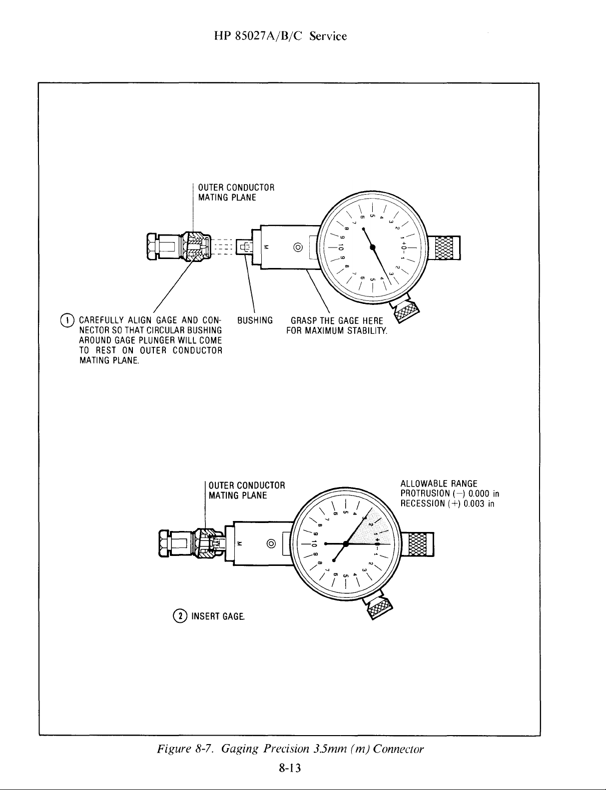
HP
85027A/B/C
OUTER
CONDUCTOR
MATING PLANE
Service
CAREFULLY
NECTORSOTHAT CIRCULAR BUSHING
AROUND
TO
RESTONOUTER
MATING
ALIGN
GAGE
PLUNGER
PLANE.
GAGE
AND
WILL
CONDUCTOR
CON
COME
OUTER
MATING
-
BUSHING
FOR
CONDUCTOR
PLANE
GRASP
MAXIMUM
THE
GAGE
HERE
STABILITY.
ALLOWABLE
PROTRUSION
RECESSION
RANGE
(—)
(+)
0.000
0.003
in
in
Figure
INSERT
8-7.
GAGE.
Gaging
Precision
8-13
3.5mm
(m)
Connector

HP
85027A/B/C
Service
Gaging
critical
critical
extreme
not critical because the
conductor
The
conductor
collet
and
Referto
how
If
damaged
instructions.
the
APC-7
diniensionsinterms
dimensions.
end
of
itself.
center
thus
to
the
which
can
Figures
useitto
center
nor
conductor
is
rigid
must
retract
colletisdamaged,
excessively
Connector:
The
the
connector
The
and
protrude
without
8-8,
gage
outer
important
center
must
serves
8-9
and
APC-7
worn,
APC-7 connectors have3parts
of
mating
conductor
coupling
conductor
recede
onlytohold
to
makecontact.
damage
8-10tosee
connectors.
a.nd
you
surfaces.
may
sleeve.
dimensions
isavery
from
when
the
can
the
the
how
other
replace
Figure
be
That
are
plane
center
Note
mated.
to
parts
the
recessed
amount
relative
thin
of
colletinplace.
that
read
of
collet.
8-10
tube
the
the
and
the
shows
or
protruding
of
recession
to
the plane
which
outer
conductor.
center
zero
the
connector
Referto
which
determine
these
parts
from
or
of
the
holds
the
Itisthe
colletisspring
APC-7
are
neither
Figure
the
and
the
protrusion
outer
center
The
center
center
gage
and
8-11for
2
their
is
collet.
loaded
8-14

RANGE
INDICATOR
INDICATES
ACTUAL
READING.
FIRST
TWO
DIGITS
OF
HP
85027A/B/C
Service
CAP
(DO
NOT USE
ASAHANDLE)
DIAL
LOCK
SCREW
RELEASE
WHEN
SCREWTOROTATE
ZEROING
DIAL
GAGE.
GRADUATED
—
(RED) READINGS INDICATE
RECESSIONOFCENTER
CONDUCTOR
+
(BLACK)
PROTRUSIONOFCENTER
CONDUCTOR
SCALE
0.0001
EXAMPLE:
INDICATES
CONDUCTORIS0.0235
DIAL
READINGS INDICATE
DIVISIONS
INCH
RECESSIONOFCENTER
INCH.
GRASP
THE
GAGE
MAXIMUM
FLAT
USE
CONNECTORS THAT
CENTER
PLUNGER
STABILITY.
MEASURING
THISTOMEASURE
COLLETINPLACE.
HERE
FOR
SURFACE
HAVE
Figure
8-8.
The A
PC-7
8-15
Connector
CALIBRATION
USE
ALIGNING
USE
IS
NOT
Gage
BLOCK
RECESSED END
PIN.
FLAT
END
WHEN
USED.
WHEN
USING
ALIGNING
PIN

USE
THIS
ALIGNMENT
END
CALIBRATION
WHEN
PINISUSED.
THE
HP 85027A/B/C
HOLD
THE
STABILITY.
BLOCK
GAGE
HERE,
Service
FOR
MAXIMUM
DO
NOT HOLD
BECAUSE
WOBBLE
THE
THE
GAGE
GAGE
TENDS
HERE,
TO
DIAL
FIRMLY
MAIN
POINTER
POINTER
ZERO
MARKS.
IF
THE
WITH
SCREW, ROTATE
AND
ZERO
TIGHTEN
RANGE
WITH
REPAIRED.
LOCK
SCREW
SEAT
CALIBRATION
AND
SMALLER
MUST
BOTH
ALIGN
MAIN
POINTERISNOTALIGNED
ZERO,
THE
POINTER
ZERO,
LOOSEN
DIAL
ARE
LOCK
THE
DIAL
UNTIL
ALIGNED,
SCREW.IFTHE
IS
NOT ALIGNED
GAGE MUST
BLOCK.
RANGE
WITH
THE
LOCK
POINTER
THEN
BE
Figure
8-9.
Zeroing
8-16
the APC-7
Gage

HP
85027A/B/C
Service
ALLOWABLE
CENTER
RANGE
COLLET
(ALL
CONNECTORS):
MUST
PROTRUDE BEYOND
PLANE
OUTER
+0.002
OF
CONDUCTOR
PROTRUSION
CENTER
(+0.002—0.010 INCH)
DO
ALIGNING
INCHTO+0.010
PLANE
OF OUTER
OF
COLLET
NOT
USE
PIN.
INCH
CONDUCTOR
0.002
—0.010
INCH
(0.05—0.25mm).
ALLOWABLE
(ALL
+0.002
+0.010 INCH
RANGE
CONNECTORS):
INCH
TO
Figure
8-10.
OUTER CONDUCTOR
PLANEOFOUTER
CONDUCTOR
CENTER COLLET
(PROTRUSION:
CENTER
(RECESSION:
CONDUCTOR
GagingAPC-7
8-17
+0.002TO+0.010
—0.002TO—0.008
Connectors
INCH)
INCH)

HP
85027A/B/C
Service
REMOVING
OLD
COLLET.
REPLACING
OLD
COLLET,ORINSERTING NEW
FORCEPS
/
COLLET.
PUSH
LIGHTLY
SNAP
INTO PLACE.
TO
BLUNT
PLASTIC
ROD
\
Figure
8-11.
Collet
Removal
and
Replacement,
8-18
APC-7Connectors
 Loading...