


Agilent
84904/5/8M
Programmable Step Attenuators
for Microwave and RF Manufacturing
Test Systems
Product Overview
•
Excellent repeatability: <0.03dB typical
•
Low insertion loss: <2.6 dB @ 50 GHz (84905M)
•
Long life: >2 million cycles

Features and description
• DC to 50 GHz frequency coverage
• Optional calibration data
• 0 to 11 dB, 0 to 60 dB, 0 to 65 dB
• 1 dB steps, 10 dB steps, 5 dB
steps respectively
• High accuracy
• Excellent reliability
In today’s fast moving technical
industries, test engineers need
components they can count on.
Agilent now offers an extension
to its existing attenuators that
combine its legendary reliability
with a higher frequency (50 GHz)
capability.
Increase frequency
For test systems that require
increased frequency capability
(50 GHz) with variable attenuation
ranges and steps the M family of
attenuators has a solution that fits
your need. Options include:
• 84904M: 0 to 11 dB in 1 dB steps
(4 section)
• 84905M: 0 to 60 dB in 10 dB
steps (3 section)
• 84908M: 0 to 65 dB in 5 dB steps
(4 section)
Reduce downtime
Agilent Technologies is the
world leader in innovating and
developing microwave accessories
for communications and aerospace
applications. Our innovative
design and strict adherence to
quality process control ensure
that each attenuator is guaranteed
to perform within warranted
specifications for its entire lifetime.
With fewer breakdowns and less
need to recalibrate, your test
platform performs better with
less downtime, creating more
throughput and revenue.
Raise your standards
All Agilent attenuators offer
excellent repeatability and long
life – up to five times the lifecycles
of the competition. Along with our
aggressive specifications for SWR,
and insertion loss, you have an
attenuator that will exceed the
expectations of even the most
demanding engineer with its
precision and durability.
Increase productivity
When you buy your attenuators
from Agilent, you will notice a
difference. Your test platforms
will run smoother, longer, and
faster, while yielding more viable
and valuable measurements.
Description
These attenuators offer repeatability
of better than 0.03 dB and excellent
life (greater than 2 million
switching cycles per section).
The M family of programmable
step attenuators offers coaxial
measurements to 50 GHz in a
compact rugged design. The first
model is the Agilent Technologies
84904M, which offers outstanding
performance with an attenuation
range of 0 to 11 dB in 1 dB steps.
The next, high frequency model, is
the Agilent 84905M, which provides
a range from 0 to 60 dB in 10 dB
steps. Last, the Agilent 84908M
provides an attenuation range from
0 to 65 dB in 5 dB steps.
Agilent’s design, seen in the
84904/6/7K and L attenuators,
sets the standard for size and
performance. High attenuation
accuracy and low SWR are achieved
through the use of miniature thinfilm attenuation cards. Insertion
loss performance is outstanding,
with less than 3.0 dB of loss at
50 GHz. Their compact design
allows for easy integration into
instruments and ATE systems.
For operating to 50 GHz the
84904/5/8M models offer the
2.4 mm connector that is the best
solution for top performance as
well as rugged and repeatable
connections. Each model in the
84904/5/8M family comes with two
female connectors (Option 101) or
may be ordered with one female
and one male connector for easy
insertion into a microwave chain
(Option 100).
Individual calibration data reports of
attenuation and SWR are available.
This data, measured with an Agilent
automatic network analyzer, can
be ordered as Option UK6.
Attenuation switching and control
These units feature the same
small solenoids and switching
circuits as the Agilent Technologies
8494/5/6/7 step attenuator family.
Switching time is a maximum
of 20 milliseconds; this includes
contact settling time. Once switched,
the units are latched with permanent
magnets, capable of withstanding
shocks over 10 Gs. The solenoids
automatically disconnect after
switching, which minimizes the
attenuators’ power requirements
and simplifies the driver circuit
design. Solenoids are available in
either 24 volt (Option 024), 15 volt
(Option 015), and 5 volt (Option
011) ranges to fit your instrument or
system requirements.
The units come equipped with
10-pin DIP headers for connecting
DC control lines. Available
accessories include a 203 mm
(8 inch) or 406 mm (16 inch) ribbon
cable (11764-60002 or 11764-60003,
respectively) with DIP-type
connectors that are compatible
with standard 14-pin DIP IC sockets.
Alternately, a 1524 mm (5 foot)
cable (11764-60001) with free wires
for direct soldering, or a 1524 mm
(5 foot) drive cable that connects
to the 11713A attenuator/switch
driver, allowing for easy integration
into GPIB-controlled automatic
test sytems (11764-60004) may
be ordered.
2

Selection switching
Figure 2 shows one attenuator
section schematic. Each section
utilizes one solenoid with dual coil
windings, one coil to switch in the
attenuator card (e.g. 10 dB) and one
coil to switch in the thru line (0 dB).
With positive voltage applied
to the common pin, the state
(attenuator card or thru line) of
a particular section is driven by
connecting its attenuator card pin
or thru pin to a negative voltage or
ground. Figure 3 defines the pin
assignments and wire color code
for the 11764-60001/60002/60003
drive cables. Table 1 is a solenoid
drive pin and attenuation guide.
Table 2 (on page 5) defines
recommended attenuation section
activation.
As a section is switched, the
internal contacts of the activated
coil open, thus shutting off current
flows. At the same time, the internal
contacts for the other coil close so
that it can be activated when
desired. Figure 1 shows a section
that has been switched to the
attenuator card position (note the
closed thru line coil contact). The
switching is “break-before-make”
type, thus momentary interruption
of the RF signal occurs at switching.
3
Figure 1: Driver and indicator circuits for one
section of an Agilent 8494/5/6/7
Typical
external
driver
RF input
Attenuation
card
To next
section
RF to
next section
of output
Attenuator card
drive pin
(e.g., pin 2)
Internal
coil contacts
Thru line
pin
(e.g., pin 1)
Figure 2: Section electrical diagram
Although all sections can be
switched simultaneously, the
attenuator driver must not allow
both pins of the same section (e.g.
Section 1, pins 1 and 2) to be
activated concurrently, or else
that section would cycle rapidly.
All terminals are “floating,” so
bipolar or unipolar power supplies
can be used.
Typical driver circuit
Figure 1 shows an economical
TTL compatibility driver circuit for
a single attenuation section that
utilizes an IC relay driver and an
inverter. A TTL “HI” input to the
driver switches in the attenuator
card, while a “LO” will activate
the thru line for that section. This
provides a complimentary driver for
the section that assures that only
one solenoid of the pair is activated
at a time.
Switch position can be indicated
remotely by utilizing the open and
closed states of the internal coil
contacts. Connected at A and B in
Figure 1 are two indicator circuits,
one providing a TTL output and
one that activates an LED. These
circuits will output a TTL “HI” (LED
lamp “ON”) if the attenuator card
is in the RF circuit, and will output
a TTL “LO” (LED lamp “OFF”) if
the thru line is in the RF circuit.
Since current is drawn through the
coil for these circuits, inadvertent
switching is prevented by limiting
the current to 5 mA.
Agilent Technologies assumes no
responsibility for the use of any
circuits described herein and makes
no representation or warranties,
express or implied, that such
circuits are free from patent
infringement.
Switch driver circuit
LED indicator circuit
▲
▲
TTL input
+5V
Inverter
IC relay driver
(DM7404N*)
*Fairchild Semiconductor
part numbers, also supplied
by other vendors:
NOTE: Additional circuit
design information may
be required from the
component manufacturers.
+5V
LED
5082-4880 (DM7406N*)
(DS75451N*)
Driver
TTL indicator circuit
TTL output
Inverter
(DM7404N*)
+24V
0.62K0.13K
4.22K
Drive
cable
A
B
4.22K
D
0.62K
Attenuator section
Thru line
drive pin
Internal
coil contacts
RF
connector
drive pin
RF in
Thru line
Attenuation card
To next section
RF to next
section
or output
GPIB attenuator/switch driver
Employing programmable step
attenuators and switches in an
automatic test system becomes an
easy task when the Agilent 11713A
attenuator/switch driver is specified
into the system.
The 11713A has all of the necessary
features to provide GPIB control of
up to two programmable attenuators
of the 8494/5/6/7 Series as well
as the 84904/5/6/7/8 Series, and
concurrently up to two electromechanical switches (e.g., the 8761B
or 8762 Series).
The 11713A includes an integral
power supply (with short circuit
protection) that can simultaneously
provide 125 milliamps at 24 volts
to all contacts for control of the
attenuators and switches, so no
external power supply is needed.
Connecting between the 11713A
and the 84904/5/8 step attenuators
is easy with the 11764-60004
drive cable.
The 11713A also features convenient
front panel keys so the user can
manually activate the individual
attenuation sections and switches
when in the “local” mode. Switching
time for the drivers is less than
10 milliseconds.
For test systems using Agilent
70000 modular measurement
system, automatic control of these
products is easy using the 70611Aattenuator/switch driver. The
70611A has a versatile, easy to
use manual interface when used
with the 70004 color display. Each
70611A is capable of driving up to
31 SPDT electromechanical switches
or a combination of several step
attenuators and switches.
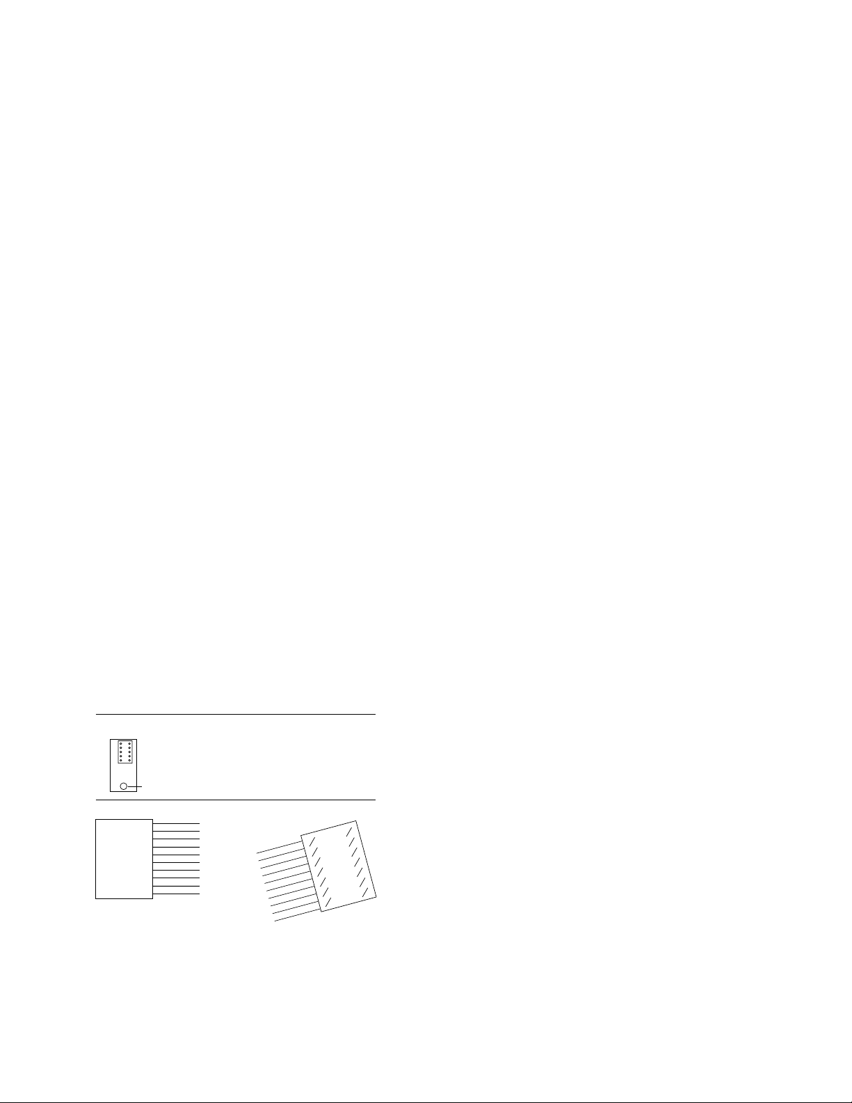
4
Attenuator
10-pin
header
RF connector
11764-60001 wire colors
1. Brown 2. Red
3. Orange 4. Yellow
5. Green 6. Blue
7. Violet 8. Gray
9. White 10. Black
12
910
11764-60002/60003
header
Brown
Red
Orange
Yellow
Green
Blue
Violet
Gray
White
Black
114
213
312
411
510
69
78
Brown
14 1
8
7
Red
Orange
Yellow
Green
Blue
Violet
Gray
White
Black
11764-60002/60003
14-pin header colors
114
213
312
411
510
6 9
7 8
Yellow
Blue
Gray
Black
Red
Orange
Green
Violet
White
Brown
Figure 3: Attenuator switching pinout
Optional calibration data
for the Agilent 84904/5/8
Use of calibration data (i.e.,
accuracy, recorded, data of a
device’s characteristics) has
always been an effective means of
reducing measurement uncertainty
at RF and microwave frequencies.
Step attenuators have long been
used as reference standards in the
measurement of gain, attenuation,
and receiver sensitivity. Since the
accuracy specifications include
margins for frequency response
and unit-to-unit variations,
calibration data can improve
overall measurement uncertainty.
Calibration data is available as
Option UK6 and is generated from
measurements made by an Agilent
8510 automatic network analyzer.
Option UK6 provides a tabular
list of attenuation and reflection
coefficients in 250 MHz steps from
1500 MHz to 50 GHz. Measurements
are traceable to NIST (National
Institute of Standards and
Technology, formerly NBS)
standards and feature very low
measurement uncertainties
(Table 3 on page 6).

5
Table 1. Solenoid pin and attenuator guide
Section: Section 1 Section 2 Section 3 Section 4
Thru Attn Thru Attn Thru Attn Thru Attn +Voltage
Model number line card line card line card line card supply
84904M
Attenuation (dB) 0 1 0 2 0 4 0 4
Attenuator actuating pin 1 2 5 8 4 9 6 7 10
11764-60001 Pin header colors BRN RED GRN GRAY YEL WHT BLU VIO BLK
11764-60004 Viking plug pin number 5 6 7 8 9 10 11 12 1
11764-60002/60003 flat header dip pin number 13 2 11 5 3 9 4 10 6
84905M
Attenuation (dB) 0 10 0 20 0 30
Attenuator actuating pin 1 2 5 8 4 9 10
11764-60001 Pin header colors BRN RED GRN GRAY YEL WHT BLK
11764-60004 Viking plug pin number 5 6 7 8 9 10 1
11764-60002/60003 flat header dip pin number 13 2 11 5 3 9 6
84908M
Attenuation (dB) 0 5 0 10 0 20 0 30
Attenuator actuating pin 1 2 5 8 4 9 6 7 10
11764-60001 Pin header colors BRN RED GRN GRAY YEL WHT BLU VIO BLK
11764-60004 Viking plug pin number 5 6 7 8 9 10 11 12 1
11764-60002/60003 flat header dip pin number 13 2 11 5 3 9 4 10 6
Recommended switching sequence: The following switching sequence (i.e.) which 4 dB section to use for the 84904M should be
followed to insure performance to specifications.)
Table 2. Attenuator section activation guide
Attenuation selected
84904M 0 dB 1 dB 2 dB 3 dB 4 dB 5 dB 6 db 7 dB 8 dB 9 dB 10 dB 11 dB
Section 1 (1 dB) X X X X X X
Section 2 (2 dB) X X X X X X
Section 3 (4 dB) X X X X X X X X
Section 4 (4 dB) X X X X
84905M 0 dB 10 dB 20 dB 30 dB 40 dB 50 db 60 dB
Section 1 (10 dB) X X X
Section 2 (20 dB) X X X
Section 3 (30 dB) X X X X
84908M 0 dB 5 dB 10 dB 15 dB 20 dB 25 db 30 dB 35 dB 40 dB 45 dB 50 dB 55 dB 60 dB 65 dB
Section 1 (5 dB) X X X X X X X
Section 2 (10 dB) X X X X X X
Section 3 (20 dB) X X X X X X
Section 4 (30 dB) X X X XXXXX
Switching notes: Attenuator actuating pins relate to 10-pin attenuator header as shown (Figure 3), NOT terminating connector on any
attached drive cable. Solenoids are magnetic latching type; drive voltage may be removed after switching. Current is self-interrupting
in less than 20 ms.

6
Table 3. Agilent 84904/5/8M attenuation data uncertanties
Attenuation (dB) DC to 2 GHz 2 to 20 GHz 20 to 40 GHz 40 to 50 Ghz
0 ±.0305 ±.0546 ±.1256 ±.1597
1-11 ±.0297 ±.0515 ±.1238 ±.1699
15 ±.0342 ±.0516 ±.1263 ±.1968
20 ±.0334 ±.0521 ±.1240 ±.1849
25 ±.0358 ±.0522 ±.1251 ±.1997
30 ±.0432 ±.0535 ±.1283 ±.2219
35 ±.0729 ±.1050 ±.2521 ±.3918
40 ±.0729 ±.1050 ±.2521 ±.3918
45 ±.0774 ±.1051 ±.2546 ±.4187
50 ±.0766 ±.1056 ±.2523 ±.4068
55 ±.0790 ±.1057 ±.2534 ±.4216
60 ±.0864 ±.1070 ±.2566 ±.4438
65 ±.1161 ±.1585 ±.3804 ±.6137
Attenuation setting
Attenuation accuracy (±–dB; referenced from 0 dB setting):
Model number 84904M
Attenuator setting (dB): 1 2 3 4 5 6 7 8 9 10 11
Frequency range
DC to 18 GHz 0.35 0.45 0.55 0.55 0.55 0.55 0.60 0.60 0.65 0.70 0.80
18 to 26.5 GHz 0.40 0.50 0.70 0.70 0.70 0.70 0.80 0.80 0.85 0.90 1.10
26.5 GHz to 40 Ghz 0.60 0.60 0.80 0.80 0.80 0.90 1.10 1.10 1.20 1.30 1.50
40 to 50 Ghz 0.60 0.70 0.80 0.80 0.80 0.90 1.10 1.10 1.20 1.30 1.50
Model number 84905M
Attenuator setting (dB): 10 20 30 40 50 60
DC to 40 GHz 0.5 0.6 0.7 1.0 1.2 1.6
40 to 50 GHz 0.7 0.8 1.0 1.3 1.5 1.8
Model number 84908M
Attenuator setting (dB): 5 10 15 20 25 30 35 40 45 50 55 60 65
DC to 40 GHz 0.5 0.5 0.6 0.6 0.7 0.7 1.0 1.0 1.2 1.2 1.6 1.6 1.8
40 to 50 GHz 0.7 0.7 0.8 0.8 1.0 1.0 1.3 1.3 1.5 1.5 1.8 1.8 2.0
1. Step-to-step accuracy is the maximum variation from the nominal step size when changing
attenuation values. Its is a second specification on accuracy, and is used in combination with the
absolute accuracy specifications to limit maximum allowable variation from nominal. Typical step-tostep accuracy for the 84905M and 84908M is ±1.0 dB to 50 GHz; for the 84904M is ± 0.5 to 50 GHz.
73.3
(2.89)
94
(3.7)
5.8
(.23)
13.3
(.52)
84904/8M 84905M
Mounting holes
4X M3X0.5X6 deep
Ø 2.6 thru
2.4 mm Connector STD
104.3
(4.11)
*6.6
(.26)
41.8
(1.65)
10.4
(.41)
5.8
(.23)
13.3
(.52)
41.8
(1.65)
41.5
(1.63)
53.8
(2.1)
74.5
(2.9)
*6.6
(.26)
10.4
(.41)
Mounting holes
4X M3X0.5X6 deep
Ø 2.6 thru
2.4 mm Connector STD
84.8
(3.3)
41.5
(1.63)
22.2
(.87)
11.1
(.44)
7.4
(.30)
21.7
(.85)
19.3
(.76)
Figure 4: Product outlines
Dimensions are in millimeters and (inches)

7
Specifications
Maximum insertion loss 84904M 84905M 84908M
DC to 40 GHz
(in dB 0 dB position, (.8 + .04*f) (.6 + .03*f) (.8 + .04*f)
f = frequency in GHz)
40 to 50 GHz 3.0 2.6 3.0
NOTE: At 75 ° C, increase insertion loss by .006*f
(where f = frequency in GHz)
SWR
DC to 12.4 GHz 1.3 1.25 1.3
12.4 to 34 GHz 1.7 1.5 1.7
34 to 40 GHz 1.8 1.7 1.8
40 to 50 Ghz 3.0 2.6 3.0
Attenuation temperature coefficient
Less then .0001 dB/dB/°C
Power sensitivity
.001 dB/Watt
RF input power (maximum)
1 Watt average, 50 Watts peak
(10 microseconds max. pulse width)
Life (minimum)
2 million cycles per section
Repeatability
0.03 dB, typical
Environmental capabilities
(Up to 2 million cycles)
Temperature, operating
–20 °C to +75 °C
Temperature, non-operating
–55 °C to +85 °C
Altitude, operating
4,570 meters (15,000 feet)
Altitude, non-operating
13,7000 meters (50,000 feet)
Humidity
Cycling 10 days, 65 °C at 95% RH
Shock, operating
10 Gs, 6 ms, on six sides, three blows
Shock, non-operating
500 Gs, 0.5 ms, in six directions
Vibration, operating
5 Gs, 34-500 Hz;
2 Gs, 500-2000Hz
EMC
Radiated interference is within the requirements of MIL-STD-461 method
RE02, VDE 0871 and CISPR Publication II
Mechanical information
Net weight 84904M 84905M 84908M
291 grams 229 grams 291 grams
(10.3 oz) (8.1 oz) (10.3 oz)
Mounting position (any)
RF connectors
2.4mm female connectors (Option 101)
2.4mm female and 2.4 mm male (Option 100)
Switching speed
Maximum 20 milliseconds including settling time
Solenoids Coil voltage Switching current Nominal coil impedance
Option 024 24 V 125 mA 185 Ohms
(20 to 30 V) (at 24 V)
Option 015 15 V 188 mA 80 Ohms
(13 to 22 V) (at 15 V)
Option 011 5 V 325 mA 17 Ohms
(4.5 to 7 V) (at 5 V)
Switching current is current per section; approximately 10 ms duration
before internal contacts open the coil circuit
Ordering information
84904M 84905M 84908M
0 to 11 dB 0 to 60 dB 0 to 65 db
1 dB steps 10 dB steps 5 dB steps
Options
Option Description
011 5 volt solenoids
015 15 volt solenoids
024 24 volt solenoids
100 2.4 mm female connector on dc drive cable end,
male 2.4 mm connector on opposite end
101 2.4 mm female connector on dc drive cable end,
female 2.4 mm connector on opposite end
UK6 Calibration data
Attenuator Accessories
Model Number Description
11764-60001 10-pin dip plug (for attenuator connection) to
1524 mm (5-foot) ribbon cable (no second connector)
11764-60002 203 mm (8-inch) ribbon cable with 14-pin headers,
female 10-pin receptacle (for attenuator connection)
11764-60003 406 mm (16 inch) ribbon cable with 14-pin headers,
female 10-pin receptacle (for attenuator connection)
11764-60004 Interconnect cable 10-pin dip plug (for attenuator
connection) to “Viking” connector (for 11713A
connection) for use with a 11713A attenuator/switch
driver

Agilent Technologies’ Test and Measurement
Support, Services, and Assistance
Agilent Technologies aims to maximize the value
you receive, while minimizing your risk and
problems. We strive to ensure that you get the
test and measurement capabilities you paid for
and obtain the support you need. Our extensive
support resources and services can help you
choose the right Agilent products for your
applications and apply them successfully. Every
instrument and system we sell has a global
warranty. Support is available for at least five
years beyond the production life of the product.
Two concepts underlie Agilent’s overall support
policy: “Our Promise” and “Your Advantage.”
Our Promise
Our Promise means your Agilent test and
measurement equipment will meet its advertised
performance and functionality. When you are
choosing new equipment, we will help you
with product information, including realistic
performance specifications and practical
recommendations from experienced test
engineers. When you use Agilent equipment,
we can verify that it works properly, help with
product operation, and provide basic measurement
assistance for the use of specified capabilities,
at no extra cost upon request. Many self-help
tools are available.
Your Advantage
Your Advantage means that Agilent offers
a wide range of additional expert test and
measurement services, which you can purchase
according to your unique technical and business
needs. Solve problems efficiently and gain a
competitive edge by contracting with us for
calibration, extra-cost upgrades, out-of-warranty
repairs, and on-site education and training,
as well as design, system integration, project
management, and other professional engineering
services. Experienced Agilent engineers and
technicians worldwide can help you maximize
your productivity, optimize the return on
investment of your Agilent instruments and
systems, and obtain dependable measurement
accuracy for the life of those products.
By internet, phone, or fax, get assistance with
all your test and measurement needs
Online assistance:
www.agilent.com/find/assist
Phone or Fax:
United States:
(tel) 1 800 452 4844
Canada:
(tel) 1 877 894 4414
(fax) (905) 282-6495
Europe:
(tel) (31 20) 547 2323
(fax) (31 20) 547 2390
Japan:
(tel) (81) 426 56 7832
(fax) (81) 426 56 7840
Latin America:
(tel) (305) 269 7500
(fax) (305) 269 7599
Australia:
(tel) 1 800 629 485
(fax) (61 3) 9210 5947
New Zealand:
(tel) 0 800 738 378
(fax) 64 4 495 8950
Asia Pacific:
(tel) (852) 3197 7777
(fax) (852) 2506 9284
Product specifications and descriptions in this
document subject to change without notice.
Copyright © 2001 Agilent Technologies
Printed in USA, December 20, 2001
5988-2475EN
 Loading...