


Errata
This manual may contain references to HP or Hewlett-Packard. Please note that Hewlett-Packard's former test
and measurement, semiconductor products and chemical analysis businesses are now part of Agilent
Technologies. To reduce potential confusion, the only change to product numbers and names has been in the
company name prefix: where a product number/name was HP XXXX the current name/number is now Agilent
XXXX. For example, model number HP8648 is now model number Agilent 8648.
Ce manuel peut contenir des références à <<HP>> ou <<Hewlett-Packard.>> Veuillez noter que les produits de
test et mesure, de semi-conducteur et d'analyse chimique qui avaient fait partie de la société Hewlett-Packard
sont maintenent une partie de la société Agilent Technologies. Pour reduire la confusion potentielle, le seul
changement aux noms de reference a été dans le préfixe de nom de société : là où un nom de référence était HP
XXXX, le nouveau nom de référence est maintenant Agilent XXXX. Par example, le HP 8648 s'appelle
maintenent Agilent 8648.
Diese Gebrauchsanweiseung kann Bezug nehmen auf die Namen HP oder Hewlett-Packard. Bitte beachten Sie,
dass ehemalige Betriebsbereiche von Hewlett-Packard wie HP-Halbleiterprodukte, HP-chemische Analysen
oder HP-Test- und Messwesen nun zu der Firma Agilent Technology gehören. Um Verwirrung zu vermeiden
wurde lediglich bei Produktname und - Nummer der vo laufende Firmenname geändert: Produkte mit dem
Namen/Nummer HP XXXX lauten nun mehr Agilent XXXX. Z.B, das Modell HP 8648 heißt nun Agilent 8648.
Questo manuale potrebbe contenere riferimenti ad HP o Hewlett-Packard. Si noti che le attività precedentemente
gestite da Hewlett-Packard nel campo di Test & Misura, Semiconduttori, ed Analisi Chimica sono ora diventate
parte di Agilent Technologies. Al fine di ridurre il rischio di confusione, l'unica modifica effettuata sui numeri di
prodotto e sui nomi ha riguardato il prefisso con il nome dell'azienda : dove precedentemente compariva "HP
XXXX" compare ora "Agilent XXXX". Ad esempio: il modello HP8648 è ora indicato come Agilent 8648.
Este manual puede hacer referencias a HP o Hewlett Packard. Las organizaciones de Prueba y Medición (Test
and Measurement), Semiconductores (Semiconductor Products) y Análisis Químico (Chemical Analysis) que
pertenecían a Hewlett Packard, ahora forman parte de Agilent Technologies. Para reducir una potencial
confusión, el único cambio en el número de producto y nombre, es el prefijo de la compañía: Si el producto solía
ser HP XXXX, ahora pasa a ser Agilent XXXX. Por ejemplo, el modelo HP8648 es ahora Agilent 8648.
Document Part Number 5971-2668
Printed in the UK September 2004
A

マニュアル・チェンジ
変更
本文中の「HP(YHP)」、または「(横河)ヒューレット・パッカード株式会社」とい
う語句を、「Agilent」、または「アジレント・テクノロジー株式会社」と変更して
ください。
ヒューレット・パッカード社の電子計測、半導体製品、化学分析ビジネス部門は分
離独立し、アジレント・テクノロジー社となりました。
社名変更に伴うお客様の混乱を避けるため、製品番号の接頭部のみ変更しておりま
す。
(例: 旧製品名 HP 4294A は、現在 Agilent 4294A として販売いたしておりま
す。)

Operating and Service Manual
Agilent 8480 Series Coaxial Power Sensors
This manual applies to the following models:
8481A
8482A
8483A
8485A
8487A
8481B
8482B
8481H
8482H
8487D
8485D
8481D
Manufacturing Part Number: 08481-90173
May 2004
© Copyright 2004 Agilent Technologies.

Notice
The material contained in this document is provided "as is," and is
subject to being changed, without notice, in future editions. Further, to
the maximum extent permitted by applicable law, Agilent disclaims all
warranties, either express or implied with regard to this manual and any
information contained herein, including but not limited to the implied
warranties of merchantability and fitness for a particular purpose.
Agilent shall not be liable for errors or for incidental or consequential
damages in connection with the furnishing, use, or performance of this
document or any information contained herein. Should Agilent and the
user have a separate written agreement with warranty terms covering
the material in this document that conflict with these terms, the
warranty terms in the separate agreement will control.
All Rights Reserved. Reproduction, adaptation, or translation without
prior written permission is prohibited, except as allowed under the
copyright laws.
1400 Fountaingrove Parkway, Santa Rosa CA, 95403-1799, USA
ii

War ranty
A copy of the specific warranty terms applicable to your Agilent
Technologies product can be obtained from your local Sales and Service
Office.
Manufacturer's Declaration
This statement is provided to comply with the requirements of the
German Sound Emission Directive, from 18 January 1991.
This product has a sound pressure emission (at the operator position)
< 70 dB(A).
Diese Information steht im Zusammenhang mit den Anforderungen der
Maschinenlärminformationsverordnung vom 18 Januar 1991.
• Sound Pressure Lp < 70 dB(A).
• At Operator Position.
• Normal Operation.
• According to ISO 7779:1988/EN 27779:1991 (Type Test).
Herstellerbescheinigung
• Schalldruckpegel Lp < 70 dB(A).
•Am Arbeitsplatz.
• Normaler Betrieb.
• Nach ISO 7779:1988/EN 27779:1991 (Typprüfung).
iii

iv

Contents
1. Introduction
General Information . . . . . . . . . . . . . . . . . . . . . . . . . . . . . . . . . . . . . . . . . .2
Instruments Covered by Manual. . . . . . . . . . . . . . . . . . . . . . . . . . . . . . .2
Description . . . . . . . . . . . . . . . . . . . . . . . . . . . . . . . . . . . . . . . . . . . . . . . .3
Dimensions . . . . . . . . . . . . . . . . . . . . . . . . . . . . . . . . . . . . . . . . . . . . . . . .5
8480 series, B-models information . . . . . . . . . . . . . . . . . . . . . . . . . . . . .5
Safety Considerations. . . . . . . . . . . . . . . . . . . . . . . . . . . . . . . . . . . . . .6
8480 series, Options . . . . . . . . . . . . . . . . . . . . . . . . . . . . . . . . . . . . . . . . .6
8485A and 8485D option 033 . . . . . . . . . . . . . . . . . . . . . . . . . . . . . . . .6
Accessories Supplied. . . . . . . . . . . . . . . . . . . . . . . . . . . . . . . . . . . . . . .6
8483A 75 ohm sensor . . . . . . . . . . . . . . . . . . . . . . . . . . . . . . . . . . . . . .7
D-model 8480 series sensors (8481D, 8485D, 8485D-033 and 8487D).7
26.5 GHz and 33 GHz Frequency operation (8485A, 8485A-033,
8485D and 8485D-033) . . . . . . . . . . . . . . . . . . . . . . . . . . . . . . . . . . . . .8
50 GHz Frequency operation (8487A and 8487D) . . . . . . . . . . . . . . . .9
Recommended Calibration Interval . . . . . . . . . . . . . . . . . . . . . . . . . . .10
Warranty . . . . . . . . . . . . . . . . . . . . . . . . . . . . . . . . . . . . . . . . . . . . . . .10
8480 Series Power Sensor Specifications . . . . . . . . . . . . . . . . . . . . . . . . .11
Supplemental Characteristics . . . . . . . . . . . . . . . . . . . . . . . . . . . . . . . .18
Installation . . . . . . . . . . . . . . . . . . . . . . . . . . . . . . . . . . . . . . . . . . . . . . . .19
Initial Inspection . . . . . . . . . . . . . . . . . . . . . . . . . . . . . . . . . . . . . . . . . .19
Original Packaging . . . . . . . . . . . . . . . . . . . . . . . . . . . . . . . . . . . . . . .19
Interconnections . . . . . . . . . . . . . . . . . . . . . . . . . . . . . . . . . . . . . . . . .19
Storage and Shipment . . . . . . . . . . . . . . . . . . . . . . . . . . . . . . . . . . . .19
Environment . . . . . . . . . . . . . . . . . . . . . . . . . . . . . . . . . . . . . . . . . . . .19
Operation . . . . . . . . . . . . . . . . . . . . . . . . . . . . . . . . . . . . . . . . . . . . . . . . .20
Environment . . . . . . . . . . . . . . . . . . . . . . . . . . . . . . . . . . . . . . . . . . . . .20
Operating Precautions . . . . . . . . . . . . . . . . . . . . . . . . . . . . . . . . . . . . .20
Power Meter Calibrations. . . . . . . . . . . . . . . . . . . . . . . . . . . . . . . . . .20
Operating Instructions . . . . . . . . . . . . . . . . . . . . . . . . . . . . . . . . . . . .21
1

Contents
Power Measurements . . . . . . . . . . . . . . . . . . . . . . . . . . . . . . . . . . . . 21
Modulation Effects. . . . . . . . . . . . . . . . . . . . . . . . . . . . . . . . . . . . . . . 21
2. General Information
Recommended Test Equipment . . . . . . . . . . . . . . . . . . . . . . . . . . . . . . . 24
Connector Care. . . . . . . . . . . . . . . . . . . . . . . . . . . . . . . . . . . . . . . . . . . . . 25
Torque . . . . . . . . . . . . . . . . . . . . . . . . . . . . . . . . . . . . . . . . . . . . . . . . . . 25
Performance Test . . . . . . . . . . . . . . . . . . . . . . . . . . . . . . . . . . . . . . . . . . . 26
Standing Wave Ratio (SWR) and Reflection Coefficient (Rho)
Performance Test . . . . . . . . . . . . . . . . . . . . . . . . . . . . . . . . . . . . . . . . . 26
Replaceable Parts . . . . . . . . . . . . . . . . . . . . . . . . . . . . . . . . . . . . . . . . . . 30
3. Service
Principles of Operation . . . . . . . . . . . . . . . . . . . . . . . . . . . . . . . . . . . . . . 36
Thermocouple Sensors . . . . . . . . . . . . . . . . . . . . . . . . . . . . . . . . . . . . . 36
Diode Sensors . . . . . . . . . . . . . . . . . . . . . . . . . . . . . . . . . . . . . . . . . . . . 37
Troubleshooting . . . . . . . . . . . . . . . . . . . . . . . . . . . . . . . . . . . . . . . . . . . . 39
Troubleshooting - Eliminating the Power Meter and Sensor Cable. . 40
Troubleshooting - Power Sensors . . . . . . . . . . . . . . . . . . . . . . . . . . . . . 40
A1 Bulkhead (Thermocouple Sensors) . . . . . . . . . . . . . . . . . . . . . . . 40
A1 Bulkhead (Diode Sensors) . . . . . . . . . . . . . . . . . . . . . . . . . . . . . . 41
A2 Power Sensor Board Assembly . . . . . . . . . . . . . . . . . . . . . . . . . . 42
Repair . . . . . . . . . . . . . . . . . . . . . . . . . . . . . . . . . . . . . . . . . . . . . . . . . . . . 43
A1 Bulkhead Assembly. . . . . . . . . . . . . . . . . . . . . . . . . . . . . . . . . . . . . 43
Repair Strategy . . . . . . . . . . . . . . . . . . . . . . . . . . . . . . . . . . . . . . . . . 43
Procedure . . . . . . . . . . . . . . . . . . . . . . . . . . . . . . . . . . . . . . . . . . . . . . 43
A2 Power Sensor Board Assembly . . . . . . . . . . . . . . . . . . . . . . . . . . . . 44
Repair Strategy . . . . . . . . . . . . . . . . . . . . . . . . . . . . . . . . . . . . . . . . . 44
Procedure . . . . . . . . . . . . . . . . . . . . . . . . . . . . . . . . . . . . . . . . . . . . . . 44
2

Contents
FET Balance Adjustment . . . . . . . . . . . . . . . . . . . . . . . . . . . . . . . . . . . . .45
Equipment Required . . . . . . . . . . . . . . . . . . . . . . . . . . . . . . . . . . . . . . .45
Test Description . . . . . . . . . . . . . . . . . . . . . . . . . . . . . . . . . . . . . . . . . . .45
FET Balance Procedure . . . . . . . . . . . . . . . . . . . . . . . . . . . . . . . . . . . . .46
Disassembly / Reassembly Procedures. . . . . . . . . . . . . . . . . . . . . . . . . . .49
Disassembly Procedure . . . . . . . . . . . . . . . . . . . . . . . . . . . . . . . . . . . . .49
Reassembly Procedures . . . . . . . . . . . . . . . . . . . . . . . . . . . . . . . . . . . . .51
A. EPM Series Power Meter (E4418B) Modification
The Material and Tools Required . . . . . . . . . . . . . . . . . . . . . . . . . . . . . . .54
Impact on Warranty . . . . . . . . . . . . . . . . . . . . . . . . . . . . . . . . . . . . . . . .54
Modification Procedure . . . . . . . . . . . . . . . . . . . . . . . . . . . . . . . . . . . . . . .55
B. Bulkhead Assemblies
Bulkhead Parts Lists. . . . . . . . . . . . . . . . . . . . . . . . . . . . . . . . . . . . . . . . .62
Bulkhead Exploded Graphics . . . . . . . . . . . . . . . . . . . . . . . . . . . . . . . . . .69
3

Contents
4

1 Introduction
This Operating and Service Manual contains information about initial
inspection, performance tests, adjustments, operation, troubleshooting
and repair of the Agilent 8480 Series Coaxial Power Sensors.
Chapter 1 1
Introduction
General Information
General Information
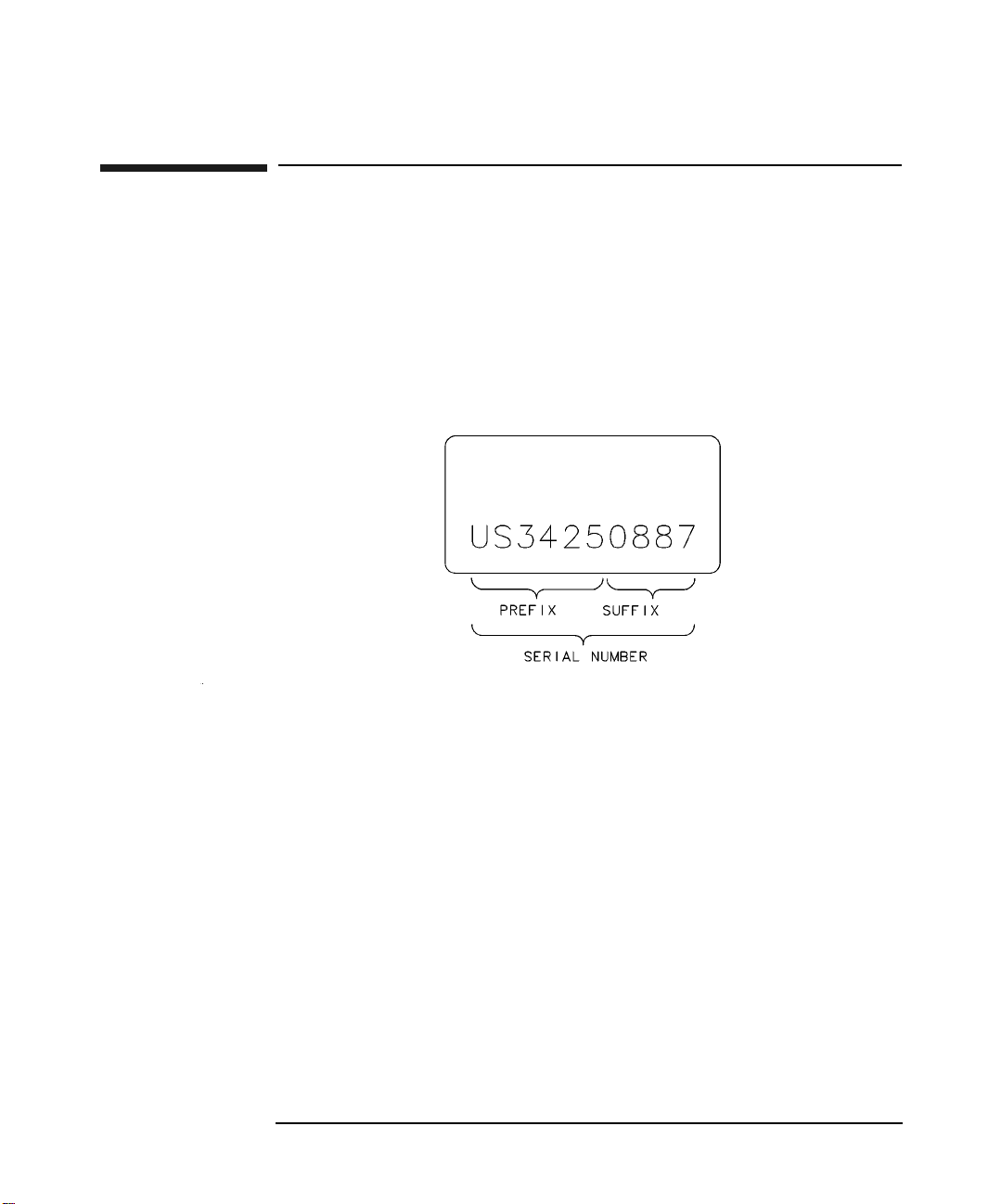
Instruments Covered by Manual
A serial number label is attached to the power sensor. The serial number
has two parts: the prefix (two letters and the first four numbers), and the
suffix (the last four numbers). Refer to the Example Serial Number
shown in Figure 1-1.
Figure 1-1 Example Serial Number
The two letters identify the country in which the unit was manufactured.
"US" represents the USA and "MY" represents Malaysia. The four
numbers of the prefix are a code identifying the date of a major design
change incorporated in your power sensor. The four digit suffix is a
sequential number and, coupled with the prefix, provides a unique
identification for each unit produced.
When seeking information about your power sensor refer to the complete
serial number and include the full prefix number and the suffix number.
For further information concerning a serial number, contact your nearest
Agilent Technologies Sales and Service office.
Chapter 12

Introduction
General Information
Description
The 8480 series power sensors are used for measuring the average power
supplied by an RF or microwave source or device-under-test (DUT). In
use, the Power Sensor is connected to the RF or microwave source and to
a compatible power meter. Suitable and compatible power meters are the
EPM series power meters (E4418B and E4419B), the EPM-P series
power meters (E4416A and E4417A) and the E1416A VXI power meter.
Discontinued and obsolete power meters that are compatible with the
8480 series sensors include the E4418A, E4419A, 435B, 436A, 437B,
438A and 70100A MMS power meter.
The 8480 series power sensors place a 50 ohm load on the RF or
microwave source, except the 8483A which has a 75 ohm load. The power
meter indicates the power dissipated in this load in mW or dBm.
The coaxial power sensors in the 8480 series measure power levels from
-70 dBm to +44 dBm (100 pW to 25 W), at frequencies from 100 kHz to
50 GHz. To cover this wide dynamic power range, both thermocouple and
diode power sensing elements are used. Both types of power sensing
elements have a maximum 50 dB dynamic range. Thermocouple sensors
have a square-law region from -30 dBm to +20 dBm, and with an
attenuator can operate up to +44 dBm. There are three model types of
thermocouple sensors in the 8480 series, covering the complete -30 dBm
to +44 dBm range.
• The A-models cover -30 dBm to +20 dBm.
• The H-models cover from -10 dBm to +35 dBm.
• The B-models cover from 0 dBm to +44 dBm.
Diode detectors (D-models) have the best sensitivity, having an operating
range from -70 dBm to -20 dBm.
Calibration factor (CAL FACTOR) data is provided on a label attached to
the power sensor's cover. Maximum uncertainties of the CAL FACTOR
data are listed in the Specifications section in page 11. This calibration
factor is used to adjust the power meter to suit the particular power
sensor and frequency being measured.
NOTE For the B-models in the 8480 series, calibration factor data is valid only
when the sensor is used with the supplied attenuator.
Chapter 1 3

Introduction
General Information
Figure 1-2 8480 Series Power Sensor Simplified Block Diagram
Cable
Balanced Chopper
Power
Input
Sensing
Element
Thermocouple
or Diode
Thermistor
AC Signal
Feedback
Autozero
Chop Signal
Chop Signal
Figure 1-2 shows a basic power sensor block diagram for both
thermocouple and diode power sensing elements. From the RF or
microwave signal input, both thermocouple and diode detector mounts
generate very low voltages, (on the order of nV or µV). The dc voltage is
proportional to the power from the RF or microwave source. As the dc
voltage is a very low-level, it requires amplification before it can be
transferred to the power meter on the standard cables.
The amplification is provided by an input amplifier assembly that
consists of a balanced chopper (sampling gate) and an AC coupled
low-noise amplifier. The dc voltage is routed on gold wires to the chopper
circuit, which converts the low-level dc voltage to an ac voltage. To do
this, the chopper is uses two field effect transistors (FET's) controlled by
a 220 Hz square-wave generated by in the power meter (the Chop
Signal). The result is an ac output signal proportional to the dc input.
The ac signal is then amplified to a relatively high-level ac signal that
can be routed to the power meter by standard cables.
The autozero signal removes residual error voltages when there is no
input RF or microwave power connected to the sensor input, and
temperature compensation is provided by a thermistor located in
amplifier feedback path.
Chapter 14

General Information
Dimensions
The physical dimensions of the power sensors differ in the model types.
This is due to the additional attenuation used to obtain the high power
performance.
Table 1-1 8480 Series Power Sensor Dimensions (including the RF
Connector)
Introduction
8480 series power
sensor models
A-models 8481A, 8482A and 8483A:
B-models 83 mm x 114 mm x 248 mm (approx. 3.25 in. x 4.50 in. x 9.75 in.)
D-models 8481D and 8485D:
H-models 38 mm wide, 30 mm high, 149 mm long (1.5 in. x 1.2 in. x 5.9 in)
CAUTION Do not disassemble the power sensor. The 8480 series power sensors are
Dimensions
38 mm wide, 30 mm high, 105 mm long (1.5 in. x 1.2 in. x 4.1 in)
8485A and 8487A:
38 mm wide, 30 mm high, 95 mm long (1.5 in. x 1.25 in. x 3.75 in.)
38 mm wide, 30 mm high, 102 mm long (1.5 in. x 1.2 in. x 4.02 in)
8487D:
38 mm wide, 30 mm high, 94 mm long (1.5 in. x 1.2 in. x 3.7 in)
static sensitive and can be easily damaged.
8480 series, B-models information
The 25 W (+44 dBm) power sensor is a calibrated combination of a 30 dB,
25 W attenuator assembly and a sensor assembly. The attenuator and
sensor assemblies are calibrated as a set and must be used together if
specified accuracies are to be obtained.
This combination is referred to as the power sensor.
Chapter 1 5

Introduction
General Information
CAUTION Removal of the D-ring that is on the sensor assembly WILL VOID THE
WARRANTY. The input connector on the sensor has a D-ring to prevent
the sensor from being connected to a high power source when its
attenuator is not attached. The sensor must only be connected to the
power meter for calibration or to the high power attenuator for RF
measurement.
Safety Considerations
The warning that follows is related to possible personal injury.
WARNING The high power attenuator contains a substrate of beryllium
oxide. Beryllium oxide in a powder form is a hazardous material
and may be injurious to your health if inhaled. Do not perform
any operation on the beryllium oxide that might generate dust.
Defective attenuator should be returned to Agilent Technologies
for proper disposal.
8480 series, Options
8485A and 8485D option 033
The 8485A and 8485D power sensors with option 033 are calibrated to
measure power levels in the 50 MHz to 33 GHz frequency range. In all
other respects, they are the same as their respective standard power
sensor.
Accessories Supplied
Accessories are required to connect various power sensors to the power
meter's 50 ohm, Power Reference (1 mW, 50 MHz) output connector
(Type-N (f)).
Chapter 16

Introduction
General Information
8483A 75 ohm sensor
The 8483A sensor is supplied with an adapter, shown in Figure 1-3. This
accessory is a mechanical adapter only, not an impedance transformer,
therefore an impedance mismatch exists that must be taken into
consideration when calibrating the power meter and sensor. The REF
CAL FACTOR, on the power sensor label, has been adjusted for the
impedance mismatch. This REF CAL FACTOR, when used to calibrate
any power meter, will allow calibration to 1.000 mW. The CAL FACTOR,
from the data on the sensor label, should be used for any power
measurements in a 75 ohm system at 50 MHz.
CAUTION Remove the mechanical adapter from the power sensor before connecting
the sensor to a 75 ohm source.
Figure 1-3 Mechanical Adapter (8483A Only)
D-model 8480 series sensors (8481D, 8485D, 8485D-033 and 8487D)
D-model sensors are supplied with a 11708A 30 dB attenuator. To
calibrate a D-model sensor, the 1 mW 50 MHz Power Reference supplied
by the power meter must be reduced to 1µW. The reference attenuator
provides the means to do this.
Chapter 1 7

Introduction
General Information
Table 1-2 11708A 30 dB attenuator characteristics
Characteristic Limits Comments
11708A accuracy at
50 MHz, 25 °C
30 ± 0.05 dB Accuracy traceable to National Institute
of Standards and Technology (NIST),
with a temperature coefficient typically
0.003 dB per °C.
Dimensions Length: 60 mm (2.4 in)
Diameter: 20 mm (0.8 in)
NOTE The 11708A 30 dB attenuator is intended for use only at the 1 mW,
50 MHz power reference of the power meter. Its function as a calibration
reference may be compromised if used for other purposes.
26.5 GHz and 33 GHz Frequency operation (8485A, 8485A-033,
8485D and 8485D-033)
8480 series sensors that operate up to 26.5 GHz and 33 GHz are fitted
with APC-3.5mm (m) connectors as standard. To convert the
APC-3.5mm (m) connector for calibration an adapter (APC-3.5 (f) to
Type-N (m)) is included with the power sensors. Figure 1-4 shows the
parts included with your power sensor.
NOTE The APC-3.5mm to Type-N adapter is intended for use only at the 1 mW,
50 MHz power reference of the power meter. Its function as a calibration
reference may be compromised if used for other purposes.
Chapter 18

General Information
Figure 1-4 8485A, 8485A-033, 8485D, 8485D-033 Sensor Accessories
50 GHz Frequency operation (8487A and 8487D)
8480 series sensors that operate up to 50 GHz are fitted with 2.4mm (m)
connectors as standard. To convert the 2.4mm (m) connector for
calibration, adapter (2.4mm (f) to Type-N (m)) is included with the power
sensors (shown in Figure 1-5).
Introduction
NOTE The 2.4mm to Type-N adapter is intended for use only at the 1 mW,
50 MHz power reference of the power meter. Its function as a calibration
reference may be compromised if used for other purposes.
Chapter 1 9

Introduction
General Information
Figure 1-5 8487A Power Sensor with Adapter
Recommended Calibration Interval
Agilent Technologies recommends a one-year calibration cycle for the
8480 series power sensors.
War ranty
The 8480 series power sensors described in this manual are warranted
and certified as indicated on the inside cover of this manual. Power
sensors are warranted only when they are operated within their
specifications, especially the maximum power handling capability. Any
power sensor returned to Agilent Technologies under warranty will be
examined carefully to determine if the failure was possibly due to
improper use.
Do not open the power sensor. Any attempt to disassemble the power
sensor will void the warranty.
Chapter 110

Introduction
8480 Series Power Sensor Specifications
8480 Series Power Sensor Specifications
NOTE These specifications are valid with EPM and EPM-P Series of power
meters.
The 8480 series thermocouple and diode power sensors provide accuracy,
stability, and SWR over a wide range of frequencies (100 kHz to 50 GHz)
and power levels (-70 dBm to +44 dBm)
NOTE Both Table 1-3 and Table 1-4 show typical uncertainty values to help
estimate measurement uncertainty. These values are only a guideline,
and are not to be used in any accurate uncertainty calculations. Refer to
your power sensor’s specific calibration report for accurate values.
Table 1-3 Typical root sum of squares (rss) uncertainty on the calibration
factor data printed on the power sensor
Freq (MHz) 8482A 8482B 8482H 8483A
0.1 0.8 1.5 0.8 1.3
0.3 0.7 1.4 0.9 1.2
1 0.7 1.4 0.9 1.1
3 0.8 1.5 0.8 1.2
10 0.8 1.5 0.8 1.2
30 0.8 1.5 0.9 1.2
50 0.7 1.4 0.8 1.2
100 0.8 1.4 0.8 1.2
300 0.8 1.4 0.8 1.2
1000 0.8 1.5 0.9 1.2
2000 0.8 1.5 0.8 1.2
4000 0.9 1.5 0.9 -
Chapter 1 11

Introduction
8480 Series Power Sensor Specifications
Table 1-4 Typical root sum of squares (rss) uncertainty on the calibration
factor data printed on the power sensor
Freq (GHz) 8481A 8481B 8481H 8481D 8485A 8485D 8487A 8487D
1 0.7 1.4 0.8 0.8 1.4 1.4 1.4 1.3
2 0.7 1.4 0.8 0.8 1.4 1.4 1.4 1.3
4 0.8 1.5 0.8 0.8 1.7 1.7 1.4 1.4
6 0.9 1.5 0.9 0.9 1.7 1.7 1.5 1.4
8 1.0 1.5 1.0 1.0 1.7 1.7 1.5 1.4
10 1.0 1.6 1.0 1.1 1.9 1.9 1.5 1.5
12 1.1 1.6 1.1 1.2 1.9 1.9 1.6 1.5
14 1.2 1.6 1.2 1.1 2.0 2.0 1.6 1.6
16 1.2 1.7 1.2 1.5 2.0 2.1 1.7 1.7
18 1.5 1.9 1.5 1.7 2.1 2.2 1.7 1.7
22 ----2.62.71.91.9
26.5 ----2.82.82.12.2
28 ----
30 ----
33 ----
34.5 ------2.32.6
37 ------2.42.7
40 ------2.53.0
42 ------2.63.2
44 ------2.93.5
46 ------3.13.8
48 ------2.93.8
50 ------3.85.0
3.1
3.2
3.7
a
a
a
2.9
3.2
3.3
a
a
a
2.2 2.3
2.3 2.4
2.3 2.6
a. These uncertainties only apply to Option 033.
Chapter 112

8480 Series Power Sensor Specifications
Table 1-5 25 Watt sensors, 1 mW to 25 W (0 dBm to +44 dBm)
Introduction
Model Frequency
Range
8481B 10 MHz to
18 GHz
8482B 100 kHz to
4.2 GHz
a. Negligible deviation except for those power ranges noted.
b. For pulses greater than 30 W, the maximum average power (Pa) is limited by the energy per pulse (E) in
W.µs according to Pa = 30-0.02 E.
Maximum
SWR
10 MHz to
2GHz: 1.10
2GHz to
12.4 GHz: 1.18
12.4 GHz to
18 GHz: 1.28
100 kHz to
2GHz: 1.10
2GHz to
4.2 GHz: 1.18
Powe r
Linearity
+35 dBm to
+44 dBm: ±4%
+35 dBm to
+44 dBm: ±4%
a
Maximum
Powe r
0°C to 35°C:
30W avg
35°C to 55°C:
25W avg
0.01 to 5.8 GHz:
500W pk
5.8 to 18 GHz:
125W pk
500W.µs / pulse
0°C to 35°C:
30W avg
35°C to 55°C:
25W avg
0.1 to 4,2 GHz:
500W pk
500W.µs / pulse
b
b
Connector
Type
Type-N(m) Net: 0.8 kg
Type-N(m) Net: 0.8 kg
Table 1-6 3 Watt sensors, 100 µW to 3 W (–10 dBm to +35 dBm)
Wei ght
(1.75 lb)
Shipping:
1.5 kg (3.25 lb)
(1.75 lb)
Shipping:
1.5 kg (3.25 lb)
Model Frequency
Range
8481H 10 MHz to
18 GHz
8482H 100 kHz to
4.2 GHz
a. Negligible deviation except for those power ranges noted.
Maximum
SWR
10 MHz to
8GHz: 1.20
8GHz to
12.4 GHz: 1.25
12.4 GHz to
18 GHz: 1.30
100 kHz to
4.2 GHz: 1.20
Powe r
Linearity
+25 dBm to
+35 dBm: ±5%
+25 dBm to
+35 dBm: ±5%
Chapter 1 13
a
Maximum
Power
3.5W avg,
100W pk
100W.µs / pulse
3.5W avg,
100W pk
100W.µs / pulse
Connector
Type
Type-N(m) Net: 0.2 kg
Type-N(m) Net: 0.2 kg
Wei ght
(0.38 lb)
Shipping:
0.5 kg ( 1.0 lb)
(0.38 lb)
Shipping:
0.5 kg ( 1.0 lb)

Introduction
8480 Series Power Sensor Specifications
Table 1-7 100 mW sensors, 1 µW to 100 mW (–30 dBm to +20 dBm)
Model Frequency
Range
8485A 50 MHz to
26.5 GHz
Option
8485A
-033
8481A 10 MHz to
26.5 MHz to
33 GHz
18 GHz
Maximum
SWR
50 MHz to 100
MHz: 1.15
100 MHz to 2
GHz: 1.10
2 GHz to 12.4
GHz: 1.15
12.4 GHz to 18
GHz: 1.20
18 GHz to 26.5
GHz: 1.25
26.5 GHz to 33
GHz: 1.40
10 MHz to 30
MHz: 1.40
30 MHz to 50
MHz: 1.18
50 MHz to 2
GHz: 1.10
2 GHz to 12.4
GHz: 1.18
12.4 GHz to 18
GHz: 1.28
Pow er
Linearity
+10 dBm to
+20 dBm: ±3%
+10 dBm to
+20 dBm: ±3%
+10 dBm to
+20 dBm: ±3%
a
Maximum
Power
300 mW avg,
15 W pk
30 W.µs / pulse
300 mW avg,
15 W pk
30 W.µs / pulse
300 mW avg,
15 W pk
30 W.µs / pulse
Connector
Type
APC -
3.5mm(m)
APC -
3.5mm(m)
Type-N(m) Net: 0.2 kg
Weight
Net: 0.2 kg
(0.38 lb)
Shipping:
0.5 kg (1.0 lb)
Net: 0.2 kg
(0.38 lb)
Shipping:
0.5 kg (1.0 lb)
(0.38 lb)
Shipping:
0.5 kg (1.0 lb)
8482A 100 kHz to
4.2 GHz
100 kHz to 300
kHz: 1.60
300 kHz to 1
MHz: 1.20
1 MHz to 2
GHz: 1.10
2 GHz to 4.2
GHz: 1.30
+10 dBm to
+20 dBm: ±3%
300 mW avg,
15W pk
30 W.µs / pulse
Type-N(m) Net: 0.2 kg
(0.38 lb)
Shipping: 0.5
kg (1.0 lb)
Chapter 114

8480 Series Power Sensor Specifications
Table 1-7 100 mW sensors, 1 µW to 100 mW (–30 dBm to +20 dBm)
Introduction
Model Frequency
Range
8483A
(75ohm)
8487A 50 MHz to
a. Negligible deviation except for those power ranges noted.
100 kHz to
2GHz
50 GHz
Maximum
SWR
100 kHz to 600
kHz: 1.80
600 kHz to 2
GHz: 1.18
50 MHz to
100 MHz: 1.15
100 MHz to
2GHz: 1.10
2 GHz to
12.4 GHz: 1.15
12.4 GHz to
18 GHz: 1.20
18 GHz to
26.5 GHz: 1.25
26.5 GHz to
40 GHz: 1.30
40 GHz to
50 GHz: 1.50
Pow er
Linearity
+10 dBm to
+20 dBm: ±3%
+10 dBm to
+20 dBm: ±3%
a
Maximum
Power
300 mW avg,
10W pk
300 mW avg,
15W pk
30 W.µs / pulse
Connector
Type
Type-N(m)
(75 ohm)
2.4 mm (m) Net: 0.14 kg
Weight
Net: 0.2 kg
(0.38 lb)
Shipping: 0.5
kg (1.0 lb)
(0.28 lb)
Shipping: 0.5
kg (1.0 lb)
Chapter 1 15

Introduction
8480 Series Power Sensor Specifications
Table 1-8 High sensitivity sensors, 100 pW to 10 µW (–70 dBm to –20 dBm)
Model Frequency
Range
b
b
10 MHz to
18 GHz
50 MHz to
26.5 GHz
50 MHz to
33 GHz
8481D
8485D
Option
8485D
-033
Maximum SWR
10 MHz to
30 MHz: 1.40
30 MHz to 4 GHz:
1.15
4 GHz to 10 GHz:
1.20
10 GHz to
15 GHz: 1.30
15 GHz to
18 GHz: 1.35
50 MHz to
100 MHz: 1.19
100 MHz to
4GHz: 1.15
4 GHz to 12 GHz:
1.19
12 GHz to
18 GHz: 1.25
18 GHz to
26.5 GHz: 1.29
26.5 GHz to
33 GHz: 1.35
Power
Linearity
-30 dBm to
-20 dBm: ±1%
-30 dBm to
-20 dBm: ±2%
-30 dBm to
-20 dBm: ±2%
Maximum
Power
a
100 mW avg,
100 mW pk
100 mW avg,
100 mW pk
100 mW avg,
100 mW pk
Connector
Type
Type-N (m) Net: 0.16 kg
APC -
3.5mm (m)
APC -
3.5mm (m)
Weight
(0.37 lb)
Shipping:
0.5 kg (1.0 lb)
Net: 0.2 kg
(0.38 lb)
Shipping:
0.5 kg (1.0 lb)
Net: 0.2 kg
(0.38 lb)
Shipping:
0.5 kg (1.0 lb)
Chapter 116

Introduction
8480 Series Power Sensor Specifications
Table 1-8 High sensitivity sensors, 100 pW to 10 µW (–70 dBm to –20 dBm)
Model Frequency
Range
b
8487D
a. Negligible deviation except for those power ranges noted.
b. Includes 11708A 30 dB attenuator for calibrating against 0 dBm, 50 MHz power reference. The 11708A
50 MHz to
50 GHz
is factory set to 30 dB ±0.05 dB at 50 MHz, traceable to NIST. SWR < 1.05 at 50 MHz.
Maximum SWR
50 MHz to
100 MHz: 1.19
100 MHz to 2
GHz: 1.15
2 GHz to 12.4
GHz: 1.20
12.4 GHz to 18
GHz: 1.29
18 GHz to 34
GHz: 1.37
34 GHz to 40
GHz: 1.61
40 GHz to 50
GHz: 1.89
Power
Linearity
-30 dBm to -20
dBm: ±2%
Maximum
Power
a
100 mW avg,
100 mW pk
10 W.µs / pulse
Connector
Type
2.4 mm (m) Net: 0.2 kg
Weight
(0.38 lb)
Shipping:
0.5 kg (1.0 lb)
Chapter 1 17

Introduction
8480 Series Power Sensor Specifications
Supplemental Characteristics
Supplemental characteristics are intended to provide additional
information, useful in applying the power sensor by giving typical
(expected) but not warranted performance parameters.
Figure 1-6 Typical CAL FACTOR and SWR vs. Frequency
SWR
SWR
Frequency (GHz)
CF
Cal Factor (%)
Chapter 118

Introduction
Installation
Installation
Initial Inspection
Inspect the shipping container. If the container or packing material is
damaged, it should be kept until the contents of the shipment have been
checked mechanically and electrically. If there is mechanical damage or if
the instrument does not pass the performance tests, notify the nearest
Agilent Technologies office. Keep the damaged shipping materials (if
any) for inspection by the carrier and an Agilent Technologies
representative.
Original Packaging
Containers and materials identical to those used in factory packaging
are available through Agilent Technologies’ offices. If the instrument is
being returned to Agilent Technologies for servicing, attach a tag
indicating the type of service required, return address, model number,
and serial number. Also, mark the container FRAGILE to assure careful
handling. In any correspondence, refer to the instrument by model
number and serial number.
Interconnections
Refer to the power meter’s User’s Guide for interconnecting instructions.
Storage and Shipment
Environment
The instrument should be stored in a clean, dry environment. The
following limitations apply to both storage and shipment:
Temper at ure
Relative humidity <95%
Altitude < 7,600 metres (25,000 ft.)
Chapter 1 19
- 40 to +75
o
C

Introduction
Operation
Operation
Environment
The operating environment for the Power Sensor should be as follows:
Temper at ure
Relative humidity <95%
Altitude < 4,572 metres (15,000 ft.)
0 to +55
o
C
Operating Precautions
Before the Power Sensor is connected, the following precautions must be
observed.
WARNING BEFORE CONNECTING THE POWER SENSOR TO ANOTHER
INSTRUMENT, ensure that the instrument and power meter are
connected to the protective (earth) ground.
Power Meter Calibrations
Power Meter to Power Sensor calibration procedures differ with the
power meter. Follow the calibration procedure located in your power
meter’s user’s guide.
Temperature Sensitivity The sensitivity of the power sensor is
influenced by ambient temperature. The sensor should be recalibrated at
each change in temperature to obtain the most accurate results. Typical
temperature sensitivity variations are shown in Figure 1-7 for the 8481D
power sensor.
Chapter 120

Figure 1-7 Typical Influence of Temperature on Sensitivity
Temperature (oC)
01020 3040 5060
-0.5
-1.0
Sensitivity
Change (dB)
Operating Instructions
To operate the Power Sensor, refer to the operating instructions in of the
power meter’s user’s guide.
Power Measurements
To correct for varying responses at different frequencies a cal factor table
is included on the Power Sensors. To use the cal factor at the frequency of
interest, adjust the power meter’s CAL FACTOR control according to the
instructions in the power meter’s user’s guide.
Introduction
Operation
Modulation Effects
When measuring RF or microwave sources that are modulated at the
chopper frequency (nominally 220 Hz), at the first or second harmonic or
submultiples of the chopper frequency, beat notes may occur. Unless
these beat notes are exactly the chopper frequency, they can usually be
eliminated by averaging (filtering) since the amplitudes are plus and
minus the actual power. These frequencies may also be avoided by
changing the modulation frequency slightly, if possible.
Refer to the power meter’s user’s guide for information on setting the
averaging (filtering).
Chapter 1 21

Introduction
Operation
Chapter 122

2 General Information
This chapter contains information about recommended equipment,
performance tests, and replacement parts of the Agilent Coaxial Power
Sensors.
Chapter 2 23

General Information
Recommended Test Equipment
Recommended Test Equipment
Table 2-1 lists the test equipment recommended to check, adjust, and
troubleshoot the Power Sensor. If substitute equipment is used, it must
meet or exceed the critical specifications to be used in place of the
recommended instruments for servicing the Power Sensor.
NOTE Check the Power Sensor’s warranty. Opening it voids the warranty.
.
Table 2-1 Recommended Test Equipment (done)
Instrument Type Critical Specifications Suggested Model
Power meter No Substitute E4418B (Modified -
See Appendix A)
Digital Voltmeter • Range: 100 mVdc to 100 Vdc
• Input Impedance: 100 mohm;
• Resolution: 4-digit
• Accuracy: ±0.05% ±1 digit
Oscilloscope • Bandwidth: dc to 50 MHz
• Sensitivity: Vertical, 50 mV/div
• Horizontal, 500 µs/div
BNC(m) to BNC(m)
(2 required)
Ohmmeter • Range: 1 - 100,000 ohm;
•Accuracy: ±5%
a. A = Adjustment, T = Troubleshooting
34401A T
54622A A,T
10503C A
34401A T
Use
A
a
Chapter 224

General Information
Connector Care
Connector Care
Keeping in mind its flammable nature, a solution of pure isopropyl or
ethyl alcohol can be used to clean connectors.
CAUTION The RF connector bead deteriorates when contacted by any chlorinated
or aromatic hydrocarbon such as acetone, trichlorethane, carbon
tetrachloride, and benzene.
Do not attempt to clean connectors with anything metallic such as pins
or paper clips.
Clean the connector face by first using a blast of compressed air. If the
compressed air fails to remove contaminants use a cotton swab dipped in
isopropyl or ethyl alcohol. If the swab is too big, use a round wooden
toothpick wrapped in a lint free cloth dipped in isopropyl or ethyl alcohol.
Torque
For operation to 18 GHz, the newer 8480 series power sensors have a
Type-N hex nut for tightening to the device-under-test or the power
meter's 1 mW Power Reference. Older 8480 series power sensors have a
knurled portion on the connector. Turn the connector nut (or knurled
portion) only to tighten, the torque should not exceed 135 N-cm (12 in-lb)
to avoid damage to the connector.
For APC3.5 mm and 2.4mm connectors the torque should not exceed
90 N-cm (8 in-lb) to avoid damage to the connector.
CAUTION Damage can occur if torque is applied to the power sensor body.
Chapter 2 25

General Information
Performance Test
Performance Test
Standing Wave Ratio (SWR) and Reflection
Coefficient (Rho) Performance Test
This section does not provide a preset test procedure since there are
several test methods and different equipment available to make these
measurements. Therefore, when measuring this specification, the actual
accuracy of the test equipment must be taken into account in order to
determine the pass/fail condition. The Maximum SWR values (also
expressed in terms of the Reflection Coefficient [Rho]) for each model of
Power Sensor are listed in Table 2-2.
Table 2-2 Power Sensor SWR and Reflection Coefficient
Frequency Maximum
SWR
(Reflection
Coefficient)
10 to 30 MHz < 1.40 (0.166)
30 to 50 MHz < 1.18 (0.083)
50 MHz to 2 GHz < 1.10 (0.048)
2 to 12.4 GHz < 1.18 (0.083)
12.4 to 18 GHz < 1.28 (0.123)
100 kHz to 300 kHz < 1.60 (0.231)
300 kHz to 1 MHz < 1.20 (0.091)
1 MHz to 2 GHz < 1.10 (0.048)
2 to 4.2 GHz < 1.30 (0.130)
System SWR
Uncertainty
8481A
8482A
Per formance
Limit (Rho -
System Rho
Uncertainty)
Actual
Measurement
Chapter 226

Table 2-2 Power Sensor SWR and Reflection Coefficient
General Information
Performance Test
Frequency Maximum
SWR
(Reflection
Coefficient)
100 kHz to 600 kHz < 1.80 (0.286)
600 kHz to 2 GHz < 1.18 (0.083)
50 to 100 MHz < 1.15 (0.070)
0.1 to 2 GHz < 1.10 (0.048)
2 to 12.4 GHz < 1.15 (0.070)
12.4 to 18 GHz < 1.20 (0.091)
18 to 26.5 GHz < 1.25 (0.111)
26.5 to 33 GHz < 1.40 (0.166)
50 to 100 MHz < 1.15 (0.070)
System SWR
Uncertainty
8483A
8485A
8487A
Per formance
Limit (Rho -
System Rho
Uncertainty)
Actual
Measurement
0.1 to 2 GHz < 1.10 (0.048)
2 to 12.4 GHz < 1.15 (0.070)
12.4 to 18 GHz < 1.20 (0.091)
18 to 26.5 GHz < 1.25 (0.111)
26.5 to 40 GHz < 1.30 (0.130)
40 to 50 GHz < 1.50 (0.20)
Chapter 2 27

General Information
Performance Test
Table 2-2 Power Sensor SWR and Reflection Coefficient
Frequency Maximum
SWR
(Reflection
Coefficient)
10 MHz to 2 GHz < 1.10 (0.048)
2 to 12.4 GHz < 1.18 (0.083)
12.4 to 18 GHz < 1.28 (0.123)
100 kHz to 2 GHz < 1.10 (0.048)
2 to 4.2 GHz < 1.18 (0.083)
10 MHz to 8 GHz < 1.20 (0.091)
8 to 12.4 GHz < 1.25 (0.112)
12.4 to 18 GHz < 1.30 (0.130)
System SWR
Uncertainty
8481B
8482B
8481H
8482H
Per formance
Limit (Rho -
System Rho
Uncertainty)
Actual
Measurement
100 kHz to 4.2 GHz < 1.20 (0.091)
10 to 30 MHz < 1.40 (0.167)
0.03 to 4 GHz < 1.15 (0.070)
4 to 10 GHz < 1.20 (0.091)
10 to 15 GHz < 1.30 (0.130)
15 to 18 GHz < 1.35 (0.112)
8481D
Chapter 228

Table 2-2 Power Sensor SWR and Reflection Coefficient
General Information
Performance Test
Frequency Maximum
SWR
(Reflection
Coefficient)
50 to 100 MHz < 1.19 (0.085)
0.1 to 4 GHz < 1.15 (0.070)
4 to 12 GHz < 1.19 (0.085)
12 to 18 GHz < 1.25 (0.112)
18 to 26.5 GHz < 1.29 (0.127)
50 to 100 MHz < 1.19 (0.085)
0.1 to 2 GHz < 1.15 (0.069)
2 to 12.4 GHz < 1.20 (0.091)
12.4 to 18 GHz < 1.29 (0.127)
18 to 34 GHz < 1.37 (0.156)
System SWR
Uncertainty
8485D
8487D
Per formance
Limit (Rho -
System Rho
Uncertainty)
Actual
Measurement
34 to 40 GHz < 1.61 (0.234)
40 to 45 GHz < 1.86 (0.301)
45 to 50 GHz < 1.89 (0.310)
Chapter 2 29
General Information
Replaceable Parts
Replaceable Parts
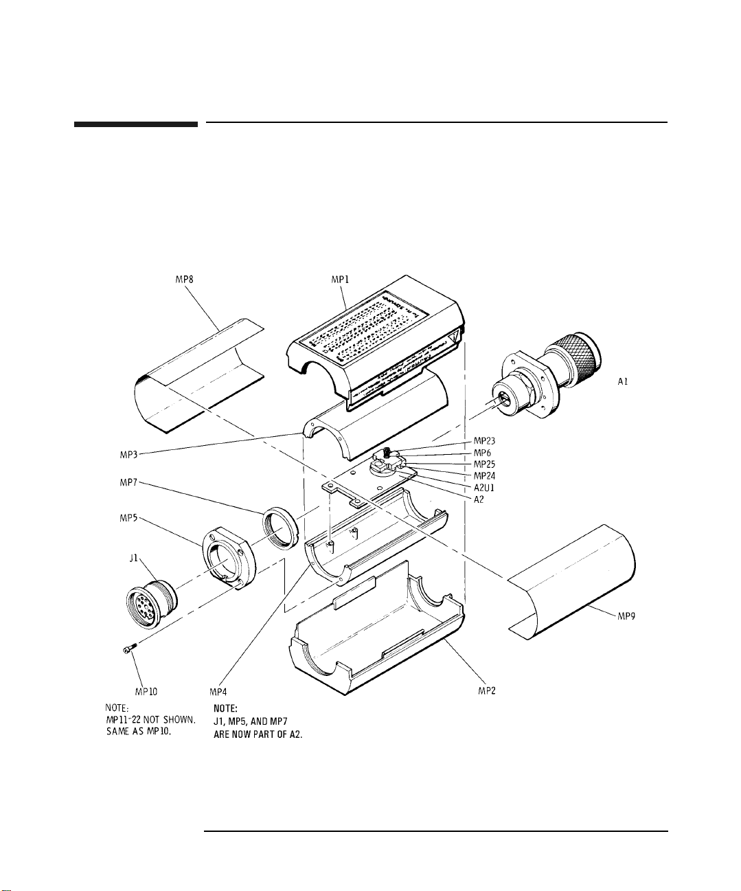
Table 2-3 to Table 2-8 are a list of replaceable parts. Figure 2-1
illustrates the major parts. To order a part listed in Table 2-3 to Table
2-8, contact your nearest Agilent Technologies Sales and Service Office.
Figure 2-1 Illustrated Major Parts Breakdown
Chapter 230

Table 2-3 Bulkhead Assembly
General Information
Replaceable Parts
Model Reference
Designator
Part
Number
Qty Description
8481A A1 08481-60004 1 Bulkhead Assembly, Type N
8481A Opt 001 A1 08481-60005 1 Bulkhead Assembly, Type APC-7
8482A A1 08482-60003 1 Bulkhead Assembly, Type N
8483A A1 08483-60003 1 Bulkhead Assembly, Type N
8485A A1 08485-60007 1 Bulkhead Assembly, 3.5mm
8485A Opt 033 A1 08485-60011 1 Bulkhead Assembly, 3.5mm
8487A A1 08487-60002 1 Bulkhead Assembly, 2.4mm
8481B A1 08481-60019 1 Bulkhead Assembly, Type N
8482B A1 08482-60011 1 Bulkhead Assembly, Type N
8481D A1 08481-60145 1 Bulkhead Assembly, Type N
8485D A1 08485-60008 1 Bulkhead Assembly, 3.5mm
8485D Opt 033 A1 08485-60012 1 Bulkhead Assembly, 3.5mm
8487D A1 08487-67002 1 Bulkhead Assembly, 2.4mm
8481H A1 08481-60014 1 20dB Bulkhead Assembly, Type N
8482H A1 08482-60009 1 20dB Bulkhead Assembly, Type N
Chapter 2 31

General Information
Replaceable Parts
Table 2-4 Power Sensor Board Assemblies
Model Reference
Designator
Part
Number
Qty Description
848xA A2 5061-0982 1 Power Sensor Board Assembly
8481B/8482B A2 08481-60039 1 Power Sensor Board Assembly
8481D/8485D/8487D A2 5061-0983 1 Power Sensor Board Assembly
8481H/8482H A2 08481-60040 1 Power Sensor Board Assembly
Table 2-5 Common Chassis Components
Reference Designator Part Number Qty Description
MP1-MP2 5040-6998 2 Plastic Shell
MP3-MP4 08481-20011 2 Chassis
MP6 1460-1978 1 Compression Spring
MP8-MP9 08481-00002 2 Shield
MP10-MP22 0515-0879 13 Screw
MP23 3030-0436 1 Screw
MP24 5040-6939 1 Clamp
MP25 5040-6940 1 Block
Chapter 232

General Information
Replaceable Parts
Table 2-6 Adapters and Attenuators
Model Part Number Qty Description
8483A 1250-0597 1 50 Ohm to 75 Ohm Coax Adapter
8485A/8485D 08485-60005 1 3.5mm to N(m) Coax Adapter
8487A/8487D 08487-60001 1 2.4mm to N(m) Coax Adapter
8481B 08498-60001 1 Coaxial Fixed 30dB Attenuator
8482B 08498-60010 1 Coaxial Fixed 30dB Attenuator
8481D/8485D/8487D 11708-60001 1 Precision 30dB Attenuator
Table 2-7 Identification Labels
Model Part Number Qty Description
8481A 08481-80002 1 8481A ID Label
8482A 08482-80002 1 8482A ID Label
8483A 08483-80001 1 8483A ID Label
8485A 08485-80002 1 8485A ID Label
8487A 08487-80001 1 8487A ID Label
8481B 08481-80004 1 8481B ID Label
8482B 08482-80003 1 8482B ID Label
8481D 08481-80011 1 8481D ID Label
8485D 08485-80003 1 8485D ID Label
8487D 08487-80004 1 8487D ID Label
8481H 08481-80003 1 8481H ID Label
8482H 08482-80001 1 8482H ID Label
Chapter 2 33

General Information
Replaceable Parts
Table 2-8 Miscellaneous Labels
Part Number Qty Description
08481-80115 1 Cal Label (Blank) - For Zebra brand printers
08486-80006 1 Cal Label (Blank) - For impact printers
08481-80005 1 Mylar Overlay - For use with Cal Label 08486-80006
08486-80005 1 Side Label - Agilent Branding
7121-2422 1 Side Label - Caution (For all models except 8487A/8487D)
08487-80002 1 Side Label - Caution (For 8487A/8487D)
00346-80011 1 Information Label (For 8481D/8485D/8487D)
Chapter 234

3 Service
This Service chapter contains information about principles of operation,
troubleshooting, and repair of the Agilent Coaxial Power Sensors.
Chapter 3 35

Service
Principles of Operation
Principles of Operation
Thermocouple Sensors
The A1 Bulkhead Assembly presents a 50 Ohm load (75 Ohm for model
8483A) to the RF source.
The RF signal is coupled through a dc blocking capacitor and absorbed by
the thermocouples, generating a dc voltage proportional to the RF input
power. The dc voltage is routed from the thermocouples to the input
amplifier via gold wires reducing unwanted thermocouple effects. The
gold wires, located in the black plastic block, pass through ferrite beads
A2E1 and A2E2. The ferrite beads increase the self-inductance of the
gold wires creating an RF choke. The result is to minimize RF
feedthrough to the A2 Power Sensor Board Assembly.
The dc output from the bulkhead assembly is applied to the two field
effect transistors (FETs) in A2U1. These transistors function as a
sampling gate or chopper. The sampling rate is controlled by a 220 Hz
square wave supplied by the power meter. The amplitude of the sampling
gate output (at pin 3 of A2U1) is a 220 Hz square wave proportional to
the power input. The sampled 220 Hz ac output is applied to the input
amplifier A2Q1, which is the input stage for an operational amplifier
The Auto Zero Feedback circuit is coupled to the power sensor from the
power meter. The dc voltage used to set the zero level is applied to the
input of FET A2U1 by using A2R1 and A1TC1 as a voltage divider.
When the Power Sensor is used with a Power Meter, the resistance to
ground from J1-K (Mount Resistor) allows the Power Meter to determine
the sensor's dynamic range.
Chapter 336

Service
Principles of Operation
Diode Sensors
The A1 Bulkhead Assembly presents a 50 Ohm load to the RF source.
A diode assembly in the bulkhead rectifies the applied RF to produce a dc
voltage that varies with the square of the RF power across the 50 Ohm
load. Thus the voltage varies with the RF power dissipated in the load.
This low level DC voltage is passed on gold wires through ferrite beads
A2E1 and A2E2. The ferrite beads increase the self-inductance of the
gold wires causing this portion of the wires to provide the properties of
an RF choke. The result is to minimize RF feedthrough to the A2 Power
Sensor Board Assembly.
The dc output from the bulkhead assembly is applied to the two field
effect transistors (FETs) in A2U1. These transistors function as a
sampling gate or chopper. The sampling rate is controlled by a 220 Hz
square wave supplied by the power meter. The amplitude of the sampling
gate output (at pin 3 of A2U1) is a 220 Hz square wave proportional to
the power input. The sampled 220 Hz ac output is applied to the input
amplifier A2Q1, which is the input stage for an operational amplifier.
The A2 Power Sensor Board Assembly also contains various components
that comprise a shaping network. This network brings about a linear
change in the amplitude of the square wave output as RF input power
changes. A shaping network is necessary in diode power sensors to
compensate for the characteristics of the thermocouple type shaping in
the power meter, and to make minor diode corrections. In order to bring
about a linear change in amplitude, the components in this network are
factory selected to match variations of the diode assembly in the
bulkhead.
The Auto Zero Feedback circuit is coupled to the power sensor from the
power meter. The dc voltage used to set the zero level is applied to the
input of FET A2U1 by using A2R1 and A1TC1 as a voltage divider.
When the Power Sensor is used with a Power Meter, the resistance to
ground from J1-K (Mount Resistor) allows the Power Meter to determine
the sensor's dynamic range.
Chapter 3 37
Service
Principles of Operation
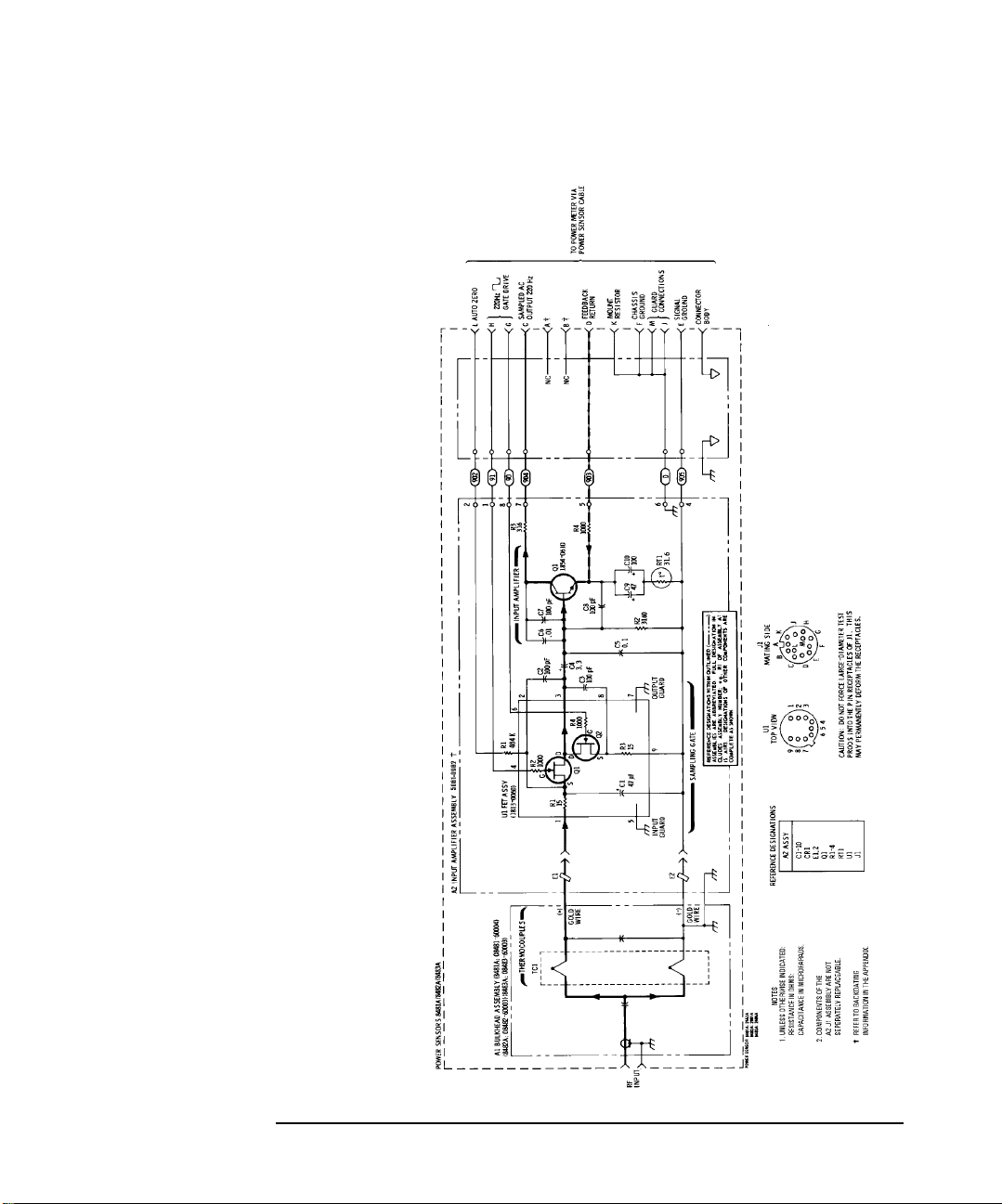
Figure 3-1 Schematic Diagram
Chapter 338

Service
Troubleshooting
Troubleshooting
Troubleshooting information is intended to first isolate the Power Sensor
or the Power Meter as the defective component. When the Power Sensor
is isolated, troubleshooting information is intended to identify the A1
Bulkhead Assembly or the A2 Power Sensor Board Assembly as the
defective component.
Before you open the Power Sensor to continue with the troubleshooting
procedures, try the substitution method of elimination. Use another
power meter, known to be in good operating condition, with the suspected
power sensor and cable. If the same problem occurs with the “known
good” power meter, substitute a “known good” power sensor cable.
Troubleshooting should be performed with the Power Sensor opened, and
the printed circuit board exposed. Refer to the “Disassembly /
Reassembly Procedures” on page 49.
When a failed assembly has been identified, refer to the repair section in
either the “A1 Bulkhead Assembly” on page 43 or the “A2 Power Sensor
Board Assembly” on page 44.
NOTE The FETs in A2U1 are light sensitive, and dc levels are shifted slightly
when the FETs are exposed.
CAUTION Excessive power damages the Power Sensor.
CAUTION Electrostatic discharge renders the Power Sensor inoperative.
Troubleshooting and Repair procedures must be carried out at a static
free workstation.
Chapter 3 39

Service
Troubleshooting
Troubleshooting - Eliminating the Power Meter and
Sensor Cable
Where a “known good” power meter and/or sensor cable is unavailable,
another means must be used to isolate the fault to the Power Sensor.
This is done by ensuring the power meter is providing the correct 220Hz
drive signal. Check the following levels of the square wave with an
oscilloscope.
• At the black/white wire: -0.05 ± 0.05 Vdc (top of square wave).
• At the brown/white wire: -9Vdc (bottom of square wave).
If the levels are incorrect, then the power meter or sensor cable is at
fault. Refer to the power meter service manual for troubleshooting
information.
If the levels are correct then the Power Sensor is at fault. Continue by
troubleshooting the A1 Bulkhead Assembly.
Troubleshooting - Power Sensors
The most common cause of Power Sensor failure is the application of
power levels beyond the specified tolerance. The second most common
cause of failure is applying torque to the body of the Power Sensor. Either
of these common causes damages the bulkhead cartridge unit (which
holds the thermocouples/diodes). If this happens, the fault causes a short
or an open between the two gold wires.
A1 Bulkhead (Thermocouple Sensors)
CAUTION Disconnect the gold wires from the A2 assembly before measuring the
resistance. Be extremely careful when measuring across the gold wires.
They are delicate and can be damaged easily.
Step 1. Disconnect all cables from the Power Sensor.
Step 2. Remove the clamp holding the two gold wires.
Step 3. Resistance measured between the two gold wires from the A1 Bulkhead
Assembly is listed in Table 3-1.
Chapter 340

Service
Troubleshooting
Table 3-1 Bulkhead Assembly Resistance
Model Measured Resistance
8481A, 8481B, 8481H, 8485A, 8487A: 200 Ohms ± 10 Ohms
8482A, 8482B, 8482H: 245 Ohms ± 12.5 Ohms
8483A: 375 Ohms ± 17.5 Ohms
If the resistance value is incorrect (failure is usually indicated by an
open circuit), then the A1 Bulkhead Assembly is defective. If the
resistance is correct then continue to test the A2 Power Sensor Board
Assembly.
A1 Bulkhead (Diode Sensors)
CAUTION Disconnect the gold wires from the A2 assembly before measuring the
voltage. Be extremely careful when measuring across the gold wires.
They are delicate and can be damaged easily.
Step 1. Disconnect all cables from the Power Sensor.
Step 2. Remove the clamp holding the two gold wires.
Step 3. Connect the Precision 30dB Attenuator to the 1mW Power Reference
connector on the power meter.
Step 4. Connect the Power Sensor to the Precision 30dB Attenuator.
NOTE Models 8485A and 8487A require 3.5mm and 2.4mm adapters
respectively.
Step 5. Turn on the 1mW Power Reference, and measure the voltage across the
two gold wires. The voltage should be between 0.9mV and 1.5mV. If the
voltage is incorrect, then the A1 Bulkhead Assembly is defective. If the
voltage is correct then continue to test the A2 Power Sensor Board
Assembly.
Chapter 3 41

Service
Troubleshooting
A2 Power Sensor Board Assembly
It is extremely rare for the A2 Assembly to fail. Eliminate the power
meter, the sensor cable, and the A1 Bulkhead Assembly before
suspecting the A2 Assembly.
In most cases, the operational amplifier (made up of A2Q1 and the first
amplifier of the power meter,) is operating correctly if the dc voltage on
the metal cover of A2Q1 (collector) is -70 ±30 mV dc.
Chapter 342

Repair
Power Sensor repair consists of replacing either the A1 Bulkhead
Assembly, or the A2 Power Sensor Board Assembly.
A1 Bulkhead Assembly
Repair Strategy
The recommended repair strategy for the A1 Bulkhead Assembly is to
completely replace it. The replacement Bulkhead is calibrated at the
factory, and is supplied with a calibration report and a new calibration
sticker for the Power Sensor.
Procedure
Step 1. Order your new or restored A1 Bulkhead Assembly from Table 2-3,
“Bulkhead Assembly,” on page 31.
Service
Repair
Step 2. Follow the disassembly and reassembly procedures for Bulkhead
removal and replacement. See “Disassembly / Reassembly Procedures”
on page 49.
Step 3. Check the FET balance using the procedure described in “FET Balance
Adjustment” on page 45. If you did not disturb the wires, it is likely that
no adjustment is necessary.
Step 4. Place the new calibration sticker on the plastic shell of the Power Sensor.
NOTE Although the recommended Bulkhead strategy is to completely replace
it, we are aware that some customers have both the ability and
experience that enables them to disassemble and repair Bulkheads to a
lower level. For this reason, Appendix B provides exploded views of the
various Bulkheads, and tables listing the parts.
Lower level Bulkhead repair can be more economical than replacement,
although this may be offset by the need to invest in sensor calibration
equipment and a SWR test set-up.
Chapter 3 43

Service
Repair
A2 Power Sensor Board Assembly
Repair Strategy
The recommended repair strategy for the A2 Power Sensor Board
Assembly is to completely replace it. Replacing this assembly is usually
less costly than the time it takes to troubleshoot and replace faulty
components.
Procedure
When replacing the A2 Power Sensor Board Assembly, some soldering is
required in order to remove and replace the wires from connector J1.
Remember that the Power Sensor is a highly sensitive device. As such, it
is affected by very small temperature differences between its
components. After performing any soldering in the unit, wait several
hours for the unit to reach thermal equilibrium before using or testing it.
1. Use a temperature controlled 600F (311C) with a zero crossover tip.
2. Use a low temperature RMA flux SN 62 solder.
3. Do not attempt to remove flux residue from around solder joints.
Using a cleaning solution may spread the flux over the entire
assembly in a thin sticky layer.
Chapter 344

FET Balance Adjustment
FET Balance Adjustment
The FET balance adjustment should be performed if the wires
connecting J1 (the sensor cable connector) to A2 (the power sensor board
assembly) have been moved. If you have replaced A2 assembly or moved
the wires during troubleshooting you need to perform this adjustment.
NOTE You do not need to perform a FET balance adjustment after an A1
bulkhead assembly replacement, if the wires between J1 and A2 have
not been disturbed.
Equipment Required
• Oscilloscope
•BNC cables (2 required)
• Power Meter (Modified as described in Appendix A)
Service
Test Description
This test applies to both thermocouple and diode power sensors. Among
the required equipment is a modified E4418B Power Meter. The High
Gain output of the power meter is connected to Channel 1 of an
oscilloscope, and the Chop Output (220Hz square wave) of the power
meter is connected to the oscilloscope trigger - the High Gain output is
the amplified version of the Power Sensor chopped signal. Ideally, when
no RF power is applied to the power sensor, the High Gain output signal
displayed on the oscilloscope is a straight line. If there is a sensor offset,
the offset signal is visible on the oscilloscope as a square wave (chopped
signal). Also, a switching transient (spike) usually occurs at the edge of
the chopped signal, due to the switching of the FET in the Power Sensor.
Sensor offset and spike balance are affected by the relative positions of
the wires connected to pins G and H of connector J1. One wire is black
and white; the other is brown and white. Moving the black and white
wire adjusts the amplitude of the switching transient (spike). Moving the
brown and white wire changes the offset. Once positioned, care must be
taken not to displace these wires. To correctly position these wires,
perform the “FET Balance Procedure” on page 46.
Chapter 3 45

Service
FET Balance Adjustment
FET Balance Procedure
Step 1. Set the Power Meter as follows:
CAL FACTOR 100%
POWER REF ON
Step 2. Connect the HIGH GAIN OUTPUT on the modified Power Meter to
CHANNEL 1 on the Oscilloscope and set it up as follows:
POSITION 0 Volts (centered)
COUPLING AC
PROBE 1:1
DISPLAY AVERAGE
AVERAGE 8
VECTORS ON
GRID ON
MAIN/DELAYED MAIN
TIME REF CENTER
TIME/DIV 500us
VOLTS/DIV 50 mV
Step 3. Connect the CHOP OUTPUT on the modified Power Meter to
CHANNEL 2 on the Oscilloscope and set it up as follows:
MODE AUTO LEVEL
TRIGGER SOURCE CHANNEL 2
VOLTS/DIV 5V
POSITION -5V
Chapter 346

Service
FET Balance Adjustment
Step 4. Connect the Power Sensor to channel A of the Power Meter.
NOTE Heat can affect the adjustments so handle the sensor as little as possible.
Step 5. Adjust the black/white and brown/white wires until the waveform shown
on the oscilloscope is similar to that shown in Figure 3-2. This shows an
example of a High Gain output signal with acceptable sensor offset and
spike balance settings.
Figure 3-2 Example of an Acceptable Waveform
Step 6. Allow no more than 50mV variance on the sensor offset step (i.e. from
top-to-top or bottom-to-bottom of the waveform). Figure 3-3 shows an
example of a High Gain output signal with an unacceptably high sensor
offset setting.
Chapter 3 47

Service
FET Balance Adjustment
Figure 3-3 Example of an Unacceptable Waveform
TIP You will find that positioning the wire for switching transients affects
the offset. Go back and forth between the two wires, positioning and
repositioning, until both adjustments are deemed acceptable.
Step 7. Reassemble the Power Sensor, ensuring that the waveform shown on the
oscilloscope does not change. If the waveform has changed, remove the
cover and readjust the black/white and brown/white wires again.
Chapter 348

Service
Disassembly / Reassembly Procedures
Disassembly / Reassembly Procedures
Disassembly Procedure
Disassemble the Power Sensor by performing the following steps:
CAUTION Disassembly must be performed in sequence described in the following
procedure, otherwise damage may be caused to the two gold wires
between the bulkhead assembly and the Power Sensor Board Assembly.
If these wires are damaged, the A1 Bulkhead Assembly must be
replaced.
NOTE Every Power Sensor has an individually prepared label on the housing. If
more than one power sensor is disassembled at a time, be sure to mate
the correct Power Sensor and housing when reassembling.
Step 1. Insert the blade of a large screwdriver between the two-piece plastic
shell at the rear of the Power Sensor. Gently pry the sections apart. (See
Figure 3-4.)
Chapter 3 49

Service
Disassembly / Reassembly Procedures
Figure 3-4 Removing the Power Sensor’s Cover
Step 2. At the other side of the sensor, again pry the cover shell sections apart.
Remove the shells and the inner magnetic shields.
Step 3. Position the Power Sensor as shown in Figure 3-5 (top). The small hole 5
should be on the left side of the RF input connector. Remove the allen cap
screws 1, 2, 10, and 13. Loosen 11 and 12. Remove the upper chassis
from the Power Sensor.
Step 4. Remove the spring clamp cap screw 7 to free the gold leads which come
from the Bulkhead Assembly.
Step 5. Remove cap screws 3, 4, and 5.
Step 6. Slide the Bulkhead Assembly straight out from the chassis.
Step 7. Remove cap screws 8, 9, 11, 12, 14, and 15.
Step 8. Lift the A2 Input Amplifier and J1 connector out of the chassis.
Chapter 350

Figure 3-5 Power Sensor Hardware Locations
Service
Disassembly / Reassembly Procedures
Reassembly Procedures
CAUTION The gold wires connecting the A1 Bulkhead Assembly and the A2 Power
Sensor Board Assembly are extremely delicate and may be easily broken.
Be careful when working around them.
Step 1. Set the printed circuit board and connector into place as shown in Figure
3-5, bottom view.
Chapter 3 51

Service
Disassembly / Reassembly Procedures
Step 2. Insert cap screws 8, 9, 11, 12, 14, and 15 but do not tighten.
Step 3. Center the circuit board so there is equal air gap between each side and
the chassis. Tighten 8, 9, 14, and 15.
Step 4. Insert screw 3, 4, and 5. Tighten only screw 5.
Step 5. With small hole 5 to the left, carefully insert the gold leads on A1
bulkhead assembly through the holes in the black plastic guide on A2
input amplifier.
Step 6. Using tweezers, position the ends of the gold wires over the electrical
pads.
CAUTION DO NOT tighten clamp screw 6 excessively or the FET circuit may be
broken.
Step 7. Place and hold plastic clamp 16 over the gold wires. As you tighten the
clamp screw, watch the compression spring. Tighten the clamp screw 7
only until the spring coils touch. Any further tightening could damage
the FET circuit.
Step 8. Place the upper chassis in position and insert cap screws 1, 2, 10, and 13.
Step 9. Tighten 1, 2, 3, and 4.
Step 10. Tighten 10, 11, 12, and 13.
Step 11. Place the plastic shells, magnetic shields, and the chassis together as
shown in Figure 2-1. Snap the plastic shells together.
Chapter 352

A EPM Series Power Meter
(E4418B) Modification
This Appendix describes the modification procedure for adapting an
E4418B Power Meter to allow it to be used for the 8480 Series Power
Sensor FET Balance Adjustment.
Appendix A 53

EPM Series Power Meter (E4418B) Modification
The Material and Tools Required
The Material and Tools Required
The following material and tools are required for this modification:
• A T-15 torque screwdriver.
• A Razor blade or Craft Knife.
• Three 30 cm lengths of AWG 20 single core wire.
• Three screw-fit BNC Female connectors
(Agilent Part Number 1250-0118).
• A fine tip marker pen and adhesive labels.
• A 10-20 Watt pencil tip soldering iron.
• 60/40 0.8 mm rosin activated core solder wire.
• A Wire stripper.
• 25 lb/in Torque Wrench - Size 7/16 in. AF.
Impact on Warranty
NOTE Please be aware that doing this modification requires you to open the
power sensor. Therefore, as stated earlier, any attempt to disassemble
the power sensor will void the warranty.
Appendix A54

EPM Series Power Meter (E4418B) Modification
Modification Procedure
Modification Procedure
CAUTION Precautions must be taken to protect the Power Meter’s PCBs from
Electrical Static Damage (ESD).
Step 1. Using the T-15 torque screwdriver, remove the two screws shown in
Figure A-1.
Figure A-1
Remove these 2 screws
Appendix A 55
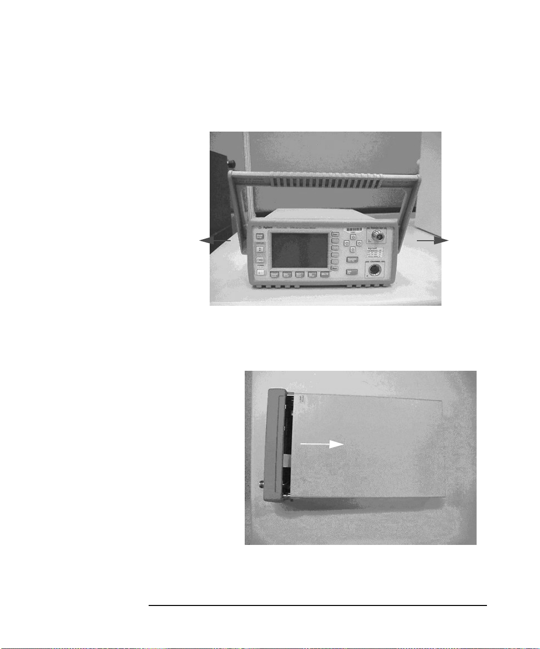
Figure A-2
EPM Series Power Meter (E4418B) Modification
Modification Procedure
Step 2. Remove the power meter handle. To remove the handle, pull the 2 ends
as shown in Figure A-2.
PullPull
Step 3. Remove the power meter cover. To remove the cover, slide it open as
shown in Figure A-3.
Figure A-3
Slide cover this direction
Appendix A56
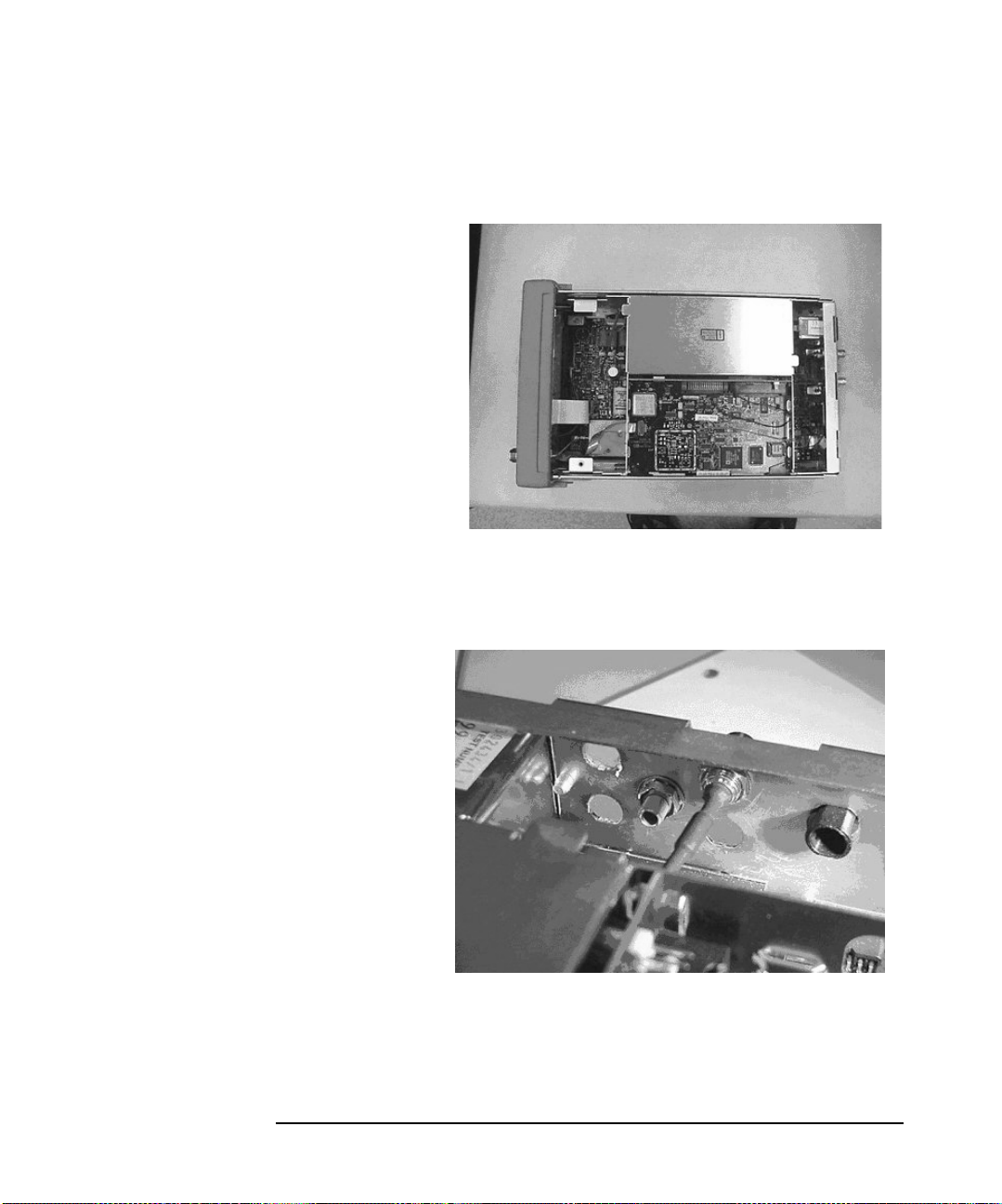
Figure A-4
EPM Series Power Meter (E4418B) Modification
Modification Procedure
Step 4. Figure A-4 shows the power meter with its cover removed.
Step 5. Use the razor blade or craft knife to remove three hole plugs in the rear
panel, as shown in Figure A-5.
Figure A-5
Appendix A 57
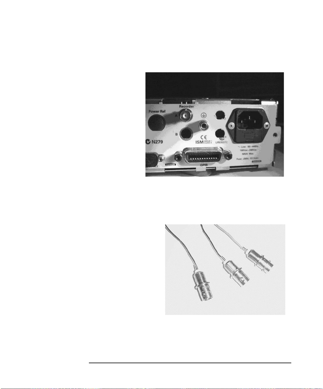
Figure A-6
EPM Series Power Meter (E4418B) Modification
Modification Procedure
Step 6. Figure A-6 shows a different view of the holes in the rear panel.
Step 7. Using the three lengths of AWG 20 wire, strip away 2cm from each end of
the wires. Solder an end of each wire onto the screw-fit BNC female
connectors, as shown in Figure A-7.
Figure A-7
Appendix A58

Figure A-8
EPM Series Power Meter (E4418B) Modification
Modification Procedure
Step 8. Securely fit the three BNC connectors into the three holes in the rear
panel, as shown in Figure A-8. Use the 25 lb/in torque wrench to tighten
the nuts.
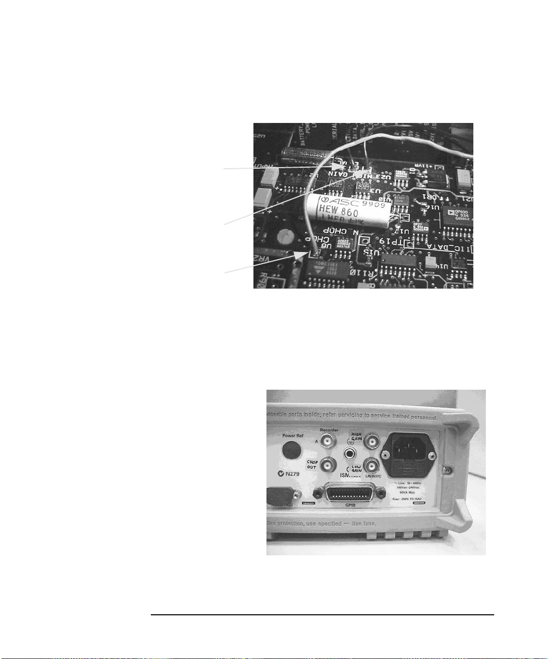
Step 9. The Measurement PCB (A6) must now be modified. The call outs in
Figure A-9 show where the three wires need to be soldered. Solder a wire
into each hole (Chop, Low Gain, and High Gain Outputs). Take care not
to over heat the PCB, as this may damage the trace.
Figure A-9
Chop Output
Appendix A 59
High Gain Output
Low Gain Output
Step 10. Figure A-10 shows a different view of the modified Measurement PCB.
Figure A-10
Step 11. Label each of the BNC connectors using the permanent marker and
EPM Series Power Meter (E4418B) Modification
Modification Procedure
Low Gain Output
High Gain Output
Chop Output
adhesive labels, as shown in Figure A-11. Refit the cover, handle, and the
rear bumper to the power meter. Tighten both screws with the T-15
torque screwdriver.
Figure A-11
Appendix A60

B Bulkhead Assemblies
This Appendix contains the material lists and exploded graphics of the
Bulkhead Assemblies.
Appendix B 61

Bulkhead Assemblies
Bulkhead Parts Lists
Bulkhead Parts Lists
Table B-1 Bulkhead Parts for the 8481A, 8481B, 8482B, and 8482B Models
Reference
Designator
MP1 Connector Nut 5021-7255 - 5021-7255
MP2 Connector Component 1250-0016 - 1250-0016
MP3 Connector Body 1250-2132 1250-1466 1250-2132
MP4 Contact Assembly 1250-0917 1250-0816 1250-0917
MP5 Insulator 5040-0306 5040-0306 5040-0306
MP6 Center Conductor -
MP7 Compression Spring 1460-0977 1460-0977 1460-0977
MP8 Sliding Contact 5020-3297 5020-3297 5020-3297
MP9 Bulkhead 08481-20015 08481-20015 08481-20015
MP10 Flat Washer 2190-0831 or
MP11 Cap Nut 08481-20016 08481-20016 08481-20016
MP12 Polyiron 08481-40006 08481-40006 -
Part Description Sensor Model
8481A
8481B
5020-3296 5020-3296 5020-3296
Cartridge Adapter
3050-0622
8481A
Opt 001
2190-0831 or
3050-0622
8482A
8482B
-
MP13 Protective Cap 1401-0099 1401-0099 1401-0099
MP14 Outer Conductor Spacer 5021-0830 or
08742-0006
MP15 Inner Conductor Spacer 5020-8540 or
08742-0005
A1 Cartridge 08481-60042 08481-60042 08482-60019
5021-0830 or
08742-0006
5020-8540 or
08742-0005
5021-0830 or
08742-0006
5020-8540 or
08742-0005
Appendix B62

Table B-2 Bulkhead Parts for the 8481D Model
Bulkhead Assemblies
Bulkhead Parts Lists
Reference
Designator
MP1 Connector Nut 5021-7255
MP2 Connector Component 1250-0016
MP3 Connector Body 1250-2132
MP4 Contact Assembly 1250-0917
MP5 Insulator 5040-0306
MP6 Center Conductor - Cartridge Adapter 5020-3296
MP7 Compression Spring 1460-0977
MP8 Sliding Contact 5020-3297
MP9 Adapter Connector 08481-20034
MP10 Center Conductor Contact 08481-20032
MP11 Insulator 5040-0306
MP12 Stepped Center Conductor 08481-20033
MP13 Rear Spacer 08481-20029
MP14 Bellows 0955-0238
Part Description Sensor Model
8481D
MP15 Feed Thru Insulator 08486-40001
MP16 Rear Housing 08481-20028
MP17 Cap Nut 08486 20007
MP18 Compensation Washer 08481-20031
MP19 Outer Conductor Spacer 5021-0830
MP20 Inner Conductor Spacer 5020-8540
MP21 Inner Conductor Spacer 08742-0005
MP22 Outer Conductor Spacer 08742-0006
A1 Cartridge 08481-60041
H1 Flat Washer 2190-0831 or 3050-0622
Appendix B 63

Bulkhead Assemblies
Bulkhead Parts Lists
Table B-3 Bulkhead Parts for the 8481H and 8482H Models
Reference
Designator
MP1 Connector Nut 5021-7255 5021-7255
MP2 Connector Component 1250-0016 1250-0016
MP3 Connector Body 1250-2132 1250-2132
MP4 Contact Assembly 1250-0917 1250-0917
MP5 Insulator 5040-0306 5040-0306
MP6 Center Conductor - Cartridge Adapter 5020-3296 5020-3296
MP7 Compression Spring 1460-0977 1460-0977
MP8 Sliding Contact 5020-3297 5020-3297
MP9 Housing 08492-2000 08492-2000
MP10 Attenuator Adapter 5021 0154 5021 0154
MP11 Sliding Contact 5020-3297 5020-3297
MP12 Compression Spring 1460-1547 1460-1547
MP13 Contact Holder 5021-0157 5021-0157
MP14 Insulator 5040-0306 5040-0306
Part Description Sensor Model
8481H 8482H
MP15 Center Conductor - Cartridge Adapter 5020-3296 5020-3296
MP16 Compression Spring 1460-0977 1460-0977
MP17 Sliding Contact 5020-3297 5020-3297
MP18 Bulkhead 08481-20015 08481-20015
MP19 Cap Nut 08481-20016 08481-20016
MP20 Protective Cap 1401-0099 1401-0099
MP21 Polyiron 08481-40006 -
MP22 Flat Washer 3050-0622 3050-0622
MP23 Flat Washer 3050-0622 3050-0622
MP24 Outer Conductor Spacer 5021-0830 or 08742-0006 5021-0830 or 08742-0006
Appendix B64

Table B-3 Bulkhead Parts for the 8481H and 8482H Models
Bulkhead Assemblies
Bulkhead Parts Lists
Reference
Designator
MP25 Inner Conductor Spacer 5020-8540 or 08742-0005 5020-8540 or 08742-0005
MP26 Flat Washer 2190-0831 or 3050-0622 -
A1 Cartridge 08481-60042 08482-60019
A2 Cartridge Assembly 08481-60011 08481-60011
Part Description Sensor Model
8481H 8482H
Appendix B 65

Bulkhead Assemblies
Bulkhead Parts Lists
Table B-4 Bulkhead Parts for the 8483A Model
Reference
Designator
MP1 Connector Nut 5021-7255
MP2 Connector Component 1250-0016
MP3 Connector Body 1250-2132
MP4 Center Conductor, 75 Ohm 08483-20003
MP5 Insulator 5020-8593
MP6 Center Contact, 75 Ohm 08483-20002
MP7 Compression Spring 1460-0526
MP8 Sliding Contact 08491-2009
MP9 Bulkhead 08481-20015
MP10 Inner Conductor Spacer 00909-20006
MP11 Cap Nut 08481-20016
MP12 Information Label 7120-4351
MP13 Protective Cap 1401-0099
MP14 Outer Conductor Spacer 5021-0830 or 08742-0006
Part Description Sensor Model
8483A
A1 Cartridge 08483-60010
Appendix B66

Table B-5 Bulkhead Parts for the 8485A and 8485D Models
Bulkhead Assemblies
Bulkhead Parts Lists
Reference
Designator
MP1 Connector Nut 08485-20005 08485-20005
MP2 Connector Component 1250-0016 1250-0016
MP3 Bulkhead 08485-20011 08485-20011
MP4 Outer External Coax 5021-7092 5021-7092
MP5 Outer Conductor Spacer 00281-20046 00281-20046
MP6 Center Conductor 5040-6958 5040-6958
MP7 Center Internal Coax 5021-7093 5021-7093
MP8 Bellows 0955-0238 0955-0238
MP9 Outer Internal Coax 5021-7091 5021-7091
MP10 Bellows Spacer 5021-9206 5021-9206
MP11 Matching Washer 5021-7094 or 08485-20024 5021-7094 or 08485-20024
MP12 Feed Thru Insulator 08486-40001 08486-40001
MP13 Cap Nut 08486-20007 08486-20007
Part Description Sensor Model
8485A
8485A Opt 033
8485D
8485D Opt 033
A1 Cartridge 08485-60015 08481-60041
C1 Fixed Capacitor, 1000Pf 50v 0160-4746 0160-4746
Appendix B 67

Bulkhead Assemblies
Bulkhead Parts Lists
Table B-6 Bulkhead Parts for the 8487A and 8487D Models
Reference
Designator
MP1 Connector Nut 5021-7081 5021-7081
MP2 Connector Component 1250-0016 1250-0016
MP3 Bulkhead 08487-20001 08487-20001
MP4 Outer External Coax 08487-20002 08487-20002
MP5 Pin Depth Washer 08487-00001 08487-00001
MP6 Center Contact 1250-2115 1250-2115
MP7 Bead Ring Assembly 1250-2107 1250-2107
MP8 Internal Center Conductor 08487-20003 08487-20003
MP9 Bellows 0955-0333 0955-0333
MP10 Outer Internal Coax 08487-20004 08487-20004
MP11 Matching Washer 08487-20006, 08487-20005,
MP12 Matching Washer 08487-20011 or 5022-2866 or
MP13 Polyiron - 08673-20046
Part Description Sensor Model
8487A 8487D
08487-20006, 08487-20005,
or 08487-20007
5022-2878 or 5022-3611
or 08487-20007
08487-20011 or 5022-2866 or
5022-2878 or 5022-3611
MP14 Feed Thru Insulator 08486-40001 08486-40001
MP15 Cap Nut 08486-20007 08486-20007
A1 Cartridge 08487-67110 08487-60004
C1 Fixed Capacitor, 1700Pf 50v 0160-6978 0160-6978
Appendix B68

Bulkhead Exploded Graphics
Figure B-1 8481A and 8481B
Bulkhead Assemblies
Bulkhead Exploded Graphics
Appendix B 69
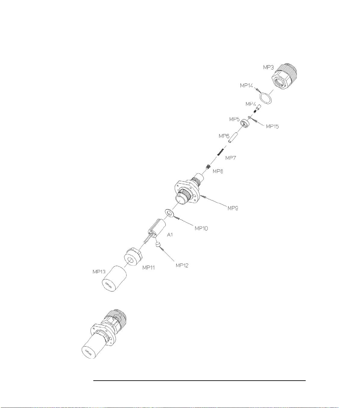
Bulkhead Assemblies
Bulkhead Exploded Graphics
Figure B-2 8481A Option 001
Appendix B70
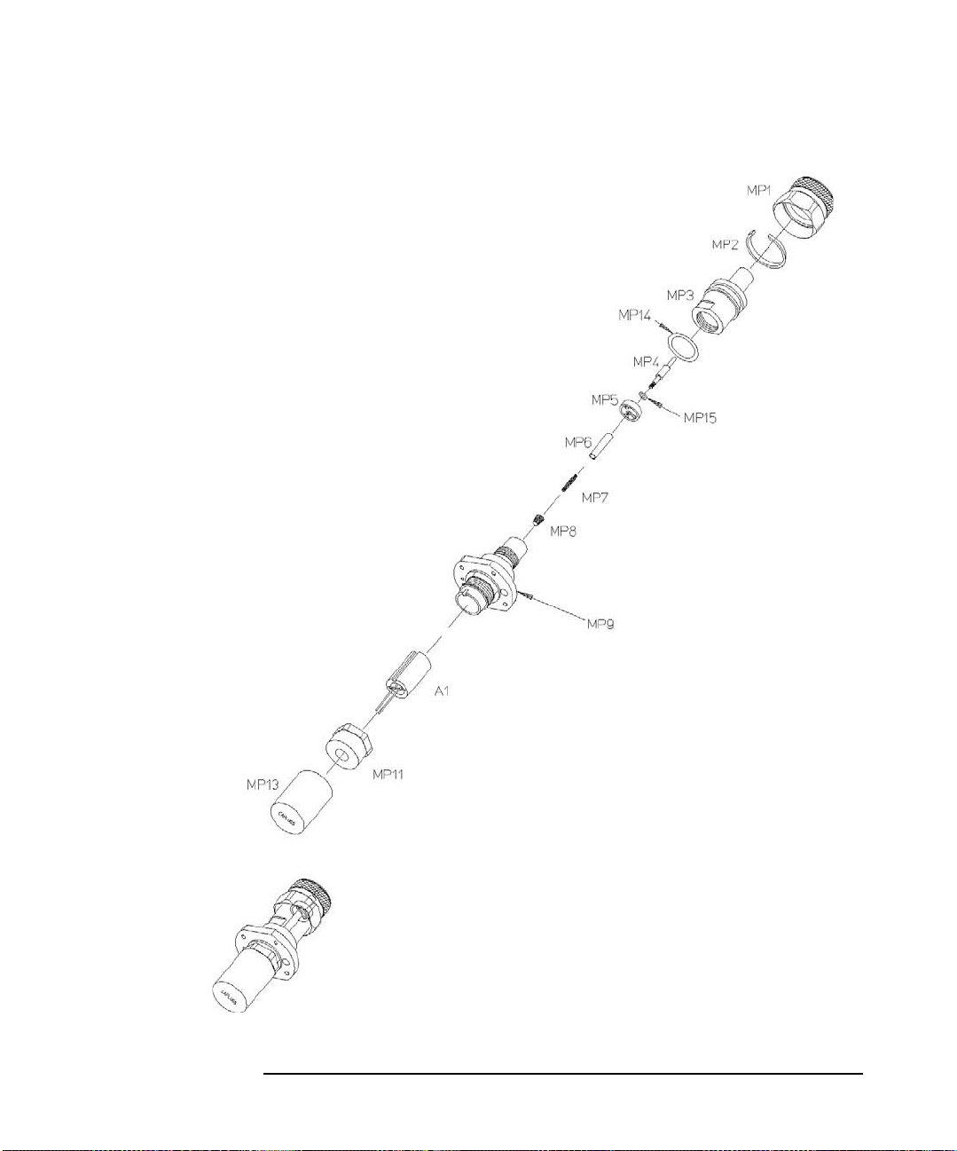
Figure B-3 8482A and 8482B
Bulkhead Assemblies
Bulkhead Exploded Graphics
Appendix B 71

Bulkhead Assemblies
Bulkhead Exploded Graphics
Figure B-4 8481D
Appendix B72
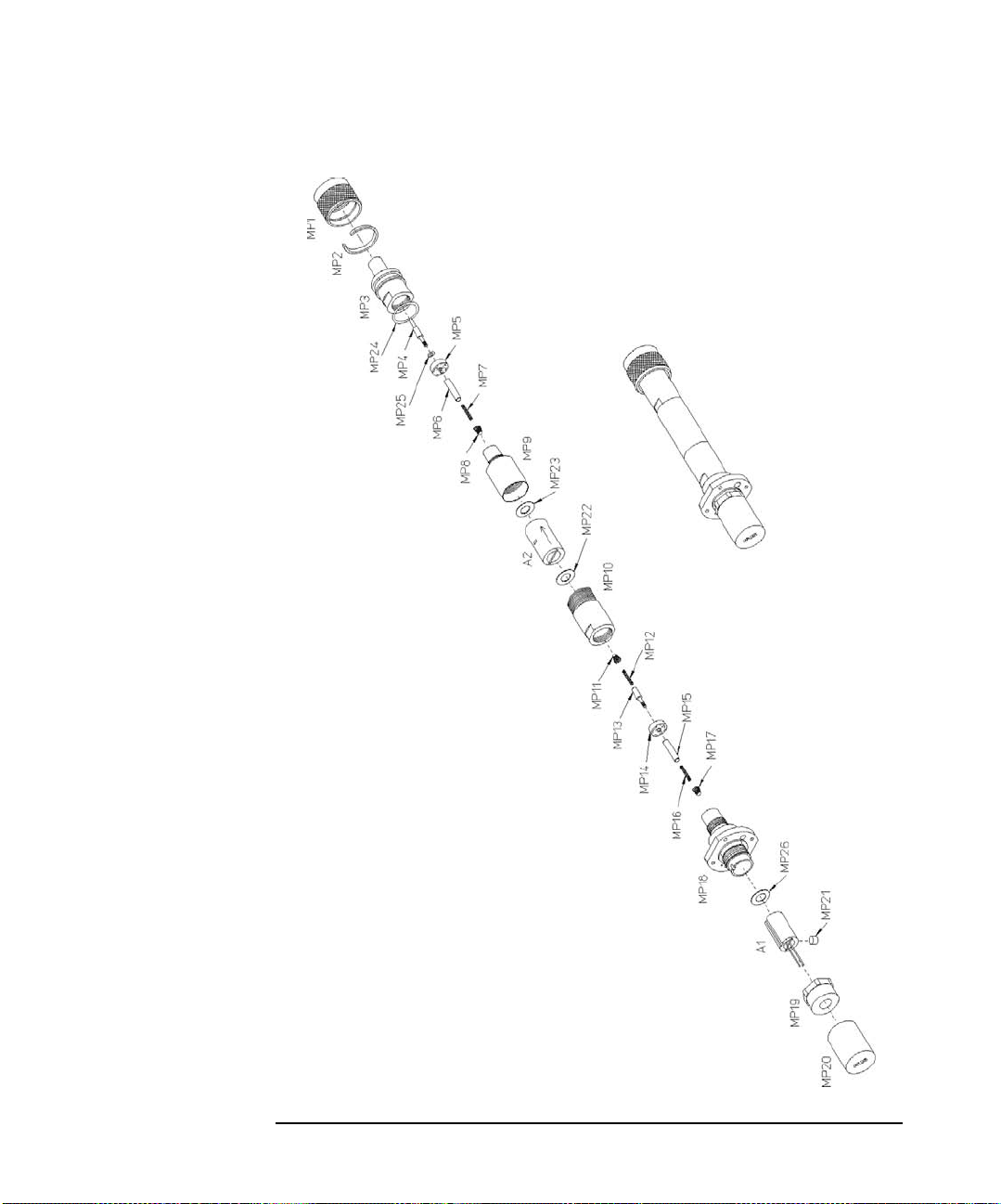
Figure B-5 8481H and 8482H
Bulkhead Assemblies
Bulkhead Exploded Graphics
8481H Only
8481H Only
Appendix B 73
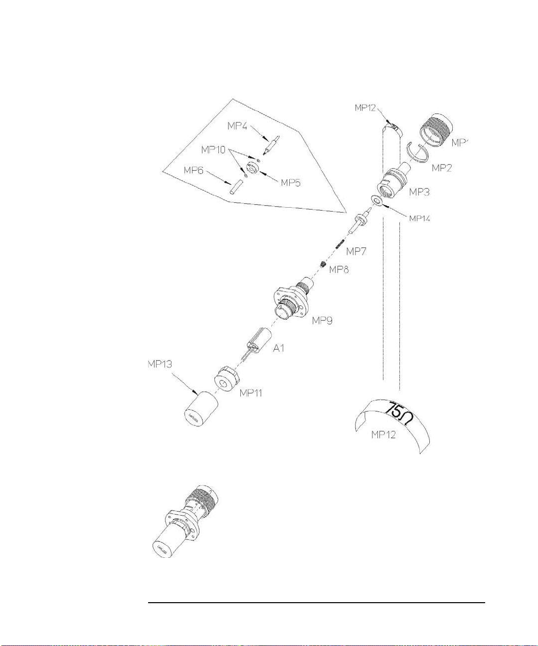
Bulkhead Assemblies
Bulkhead Exploded Graphics
Figure B-6 8483A
Appendix B74
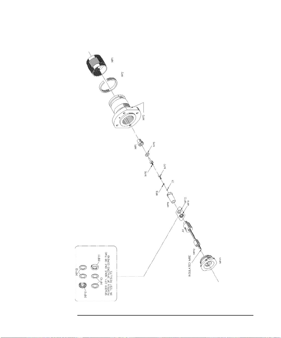
Bulkhead Exploded Graphics
Figure B-7 8485A, 8485A Opt 033, 8485D, and 8485D Opt 033
Bulkhead Assemblies
Appendix B 75
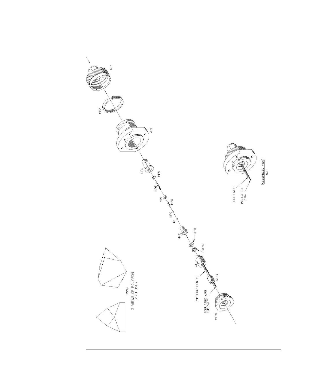
Bulkhead Assemblies
Bulkhead Exploded Graphics
Figure B-8 8487A and 8487D
Appendix B76
 Loading...