

Page 1

Programming Guide
HP
83751A/B
and HP
Synthesized Sweeper
83752A/B
Page 2

HP
part number: 83750-90005
Master set: 83750-90002
Printed in USA March 1997
Serial Numbers.
Supersedes: October 1994
This manual applies directly to instruments with serial
prel% 3447A
and
below.
This manual also applies to firmware revision 2.0 and above. For
Grmware
revisions below 2.0 contact your nearest Hewlett-Packard service center for a
firmware upgrade.
Notice.
The information contained in this document is subject to change without
notice.
Hewlett-Packard makes no warranty of any
ldnd
with regard to this material,
including but not limited to, the implied warranties of merchantability and
fitness for a particular purpose. Hewlett-Packard shall not be liable for errors
contained herein or for incidental or consequential damages in connection
with the furnishing, performance, or use of this material.
@Copyright Hewlett-Packard Company
All
Rights
Reserved. Reproduction, adaptation, or translation without prior
1993,1997
written permission is prohibited, except as allowed under the copyright laws.
1400 Fountaingrove Parkway, Santa Rosa, CA 95403-1799, USA
Page 3

Certification
Hewlett-Packard Company certifies that this product met its published
specifications
further certifies that its calibration measurements are traceable to the United
States National Institute of Standards and Technology, to the extent allowed
by the Institute’s calibration facility, and to the calibration facilities of other
International Standards Organization members.
Regulatory Information.
at the time of shipment from the factory. Hewlett-Packard
The User’s Guide contains
SCPI Conformance Information is found in Chapter 5, “SCPI Conformance
Information.
”
ISO/IEC
regulatory information.
. . .
ill
Page 4

Warranty
This Hewlett-Packard instrument product is warranted against defects in
material and workmanship for a period of one year from date of shipment.
During the warranty period, Hewlett-Packard Company will, at its option,
either repair or replace products which prove to be defective.
For warranty service or repair, this product must be returned to a service
facility designated by Hewlett-Packard. Buyer shall prepay shipping charges
to Hewlett-Packard and Hewlett-Packard shall pay shipping charges to return
the product to Buyer. However, Buyer shah pay
and taxes for products returned to Hewlett-Packard from another country.
alI
shipping charges, duties,
Hewlett-Packard warrants that its software and
Hewlett-Packard for use with an instrument will execute its programming
instructions when properly installed on that instrument. Hewlett-Packard
does not warrant that the operation of the instrument, or software, or
Ermware will be uninterrupted or error-free.
LIMITATION OF WARRANTY
The foregoing warranty shah not apply to defects resulting from improper
or inadequate maintenance by Buyer, Buyer-supplied software or
interfacing, unauthorized modification or misuse, operation outside of the
environmental specifications for the product, or improper site preparation
or maintenance.
NO OTHER WARRANTY IS EXPRESSED OR IMPLIED. HEWLETT-PACKARD
SPECIFICALLY DISCLAIMS THE IMPLIED WARRANTIES OF
MERCHANTABILITY AND FITNESS FOR A PARTICULAR PURPOSE.
EXCLUSIVE REMEDIES
THE REMEDIES PROVIDED HEREIN ARE BUYER’S SOLE AND EXCLUSIVE
REMEDIES. HEWLETT-PACKARD SHALL NOT BE LIABLE FOR ANY
DIRECT, INDIRECT, SPECIAL, INCIDENTAL, OR CONSEQUENTIAL
DAMAGES, WHETHER BASED ON CONTRACT, TORT, OR ANY OTHER
LEGAL THEORY.
firmware
designated by
iv
Page 5

Assistance
Product maintenance agreements and other customer assistance agreements
are available
Fbr any assistance, contact your nearest Hewlett-Packard Sales and service
Ome.
for
Hewlett-Packard products.
V
Page 6

Safety Notes
The following safety notes are used throughout this manual. Familiarize
yourself with each of the notes and its meaning before operating this
instrument.
CAUTION
WARNING
The caution note denotes a hazard. It calls attention to a procedure which,
if not correctly performed or adhered to, could result in damage to or
destruction of the instrument. Do not proceed beyond a caution note until
the indicated conditions are fully understood and met.
The warning note denotes a hazard. It calls attention to a procedure
which, if not correctly performed or adhered to, could result in injury or
loss of life. Do not proceed beyond a
warnzing
note until the indicated
conditions are fully understood and met.
Instruction The instruction manual symbol. The product is marked with this symbol when it is necessary
Manual
for the user to refer to the instructions in the manual.
vi
Page 7

General Safety Considerations
WARNING
WARNING
CAUTION
Before this instrument is switched on, make sure it has been properly
grounded through the protective conductor of the ac power cable to a
socket outlet provided with protective earth contact.
Any interruption of the protective (grounding) conductor, inside or
outside the instrument, or disconnection of the protective earth terminal
can result in personal injury.
There are many points in the instrument which can, if contacted, cause
personal injury. Be extremely careful.
Any adjustments or service procedures that require operation of the
instrument with protective covers removed should be performed only by
trained service personnel.
Before this
instrument is switched on, make sure its primary power circuitry
has been adapted to the voltage of the ac power source.
Failure to set the ac power input to the correct voltage could cause damage to
the instrument when the ac power cable is plugged in.
Vii
Page 8

How to Use This Guide
This guide uses the following conventions.
(Front-Panel
Sof
Screen Text
K~-J
tkey
This represents a key physically located on the instrument.
This indicates a “softkey, II a key whose label is determined
by the instrument’s
This indicates text displayed on the instrument’s screen.
firmware.
Vlll
. . .
Page 9

Contents
1. Getting Started Programming
HP-IB General Information
Interconnecting Cables
Instrument Addresses
HP-IB Instrument Nomenclature
Listener
Talker
Controller
Programming the Sweeper
HP-IB Command Statements
Abort
Related statements used by some computers
Remote
Some BASIC examples
Local
Lockout
A BASIC example
Local
Some BASIC examples
Clear
Some BASIC examples
Related statements used by some computers
output
A BASIC example
Related statements used by some computers
Enter
Related statements used by some computers
Getting Started with SCPI
Definitions of Terms
Standard Notation
Command Mnemonics
Angle Brackets
How to Use Examples
Command Examples
Response Examples
Essentials for Beginners
Program and Response Messages
....................
.....................
...................
......................
.....................
...................
................
......................
......................
......................
................
......................
.................
.................
.................
..............
...............
...............
..........
.............
............
....
..............
..............
..............
....
....
....
..............
..............
...............
...............
...............
...............
..........
l-3
l-3
1-3
l-4
l-4
l-4
l-4
l-4
l-5
l-6
l-6
l-7
l-7
l-8
l-8
l-8
1-8
l-9
l-9
l-9
l-10
l-11
l-11
l-12
1-13
1-14
l-15
1-16
l-16
l-16
l-16
l-17
1-17
l-18
l-19
Contents- 1
Page 10

Forgiving Listening and Precise Talking
Types of Commands
Subsystem Command Trees
The Command Tree Structure
Paths Through the Command Tree
Subsystem Command Tables
Reading the Command Table
More About Commands
Query and Event Commands
Implied Commands
Optional Parameters
Program Message Examples
Example 1
Example 2
Example 3
Example 4
Parameter Types
Numeric Parameters
Extended Numeric Parameters
Discrete Parameters
Boolean Parameters
Reading Instrument Errors
Example Programs
Example Program
Program Comments
Details of Commands and Responses
Program Message Syntax
SCPI Subsystem Command Syntax
Common Command Syntax
Response Message Syntax
SCPI Data Types
Parameter Types
Numeric Parameters
Extended Numeric Parameters
Discrete Parameters
Boolean Parameters
Response Data Types
Real Response Data
Integer Response Data
Discrete Response Data
String Response Data
...................
...................
...................
...................
................
.............
............
...........
..............
...........
...............
...............
............
.................
...............
...............
...............
.............
................
................
...............
..............
.............
.............
.................
.................
...............
...............
...............
...............
...............
..............
.............
..............
......
..........
........
..........
..........
.........
..........
1-19
l-19
1-21
l-21
1-21
l-24
l-25
l-26
l-26
l-26
l-26
l-27
l-27
l-27
l-28
l-28
l-29
l-29
l-30
l-31
l-31
1-32
l-33
l-33
l-35
l-36
l-37
l-38
l-39
l-40
1-41
l-42
1-42
l-43
l-44
l-44
l-45
l-45
l-45
1-46
l-46
Contents-2
Page 11
Programming Typical Measurements
Using the Example
Use of the Command Tables
HP-IB Check, Example Program 1
Program Comments
Local Lockout Demonstration, Example Program
Program Comments
Setting Up A Typical Sweep, Example Program 3 .
Program Comments
Queries, Example Program 4
Program Comments
Saving and Recalling States, Example Program 5
Program Comments
Looping and Synchronization, Example Program 6 .
Program Comments
Using the
Program Comments
Using the User Flatness Correction Commands,
*WA1
Example Program 8
Programming the Status System
General Status Register Model
Condition Register
Transition Filter
Event Register
Enable Register
An Example Sequence
HP 83750 Series Status Register Model
Synthesized Sweeper Status Groups
The Status Byte
The Standard Event Status Group
The Standard Operation Status Group
The Questionable Data Status Group
Status Register System Programming Example
Programming the Trigger System
Generalized Trigger Model
Description of Triggering in Sweepers
Advanced Trigger Configurations
Trigger Keyword Definitions
ABORt
IMMediate
SOURce
Programs
.............
.............
.............
.............
.............
.............
Command, Example Program 7
.............
..............
.............
..............
...............
...............
............
Group
..................
.................
..................
...........
...........
........
...........
..........
........
..........
.........
.........
......
.......
.......
.....
.....
.........
......
.......
..........
l-47
l-47
. .
. .
. .
. .
2
. .
. .
. .
. .
. .
. .
.
. .
. .
. .
. .
.
. .
l-48
l-51
l-51
l-52
l-53
l-54
l-55
l-56
l-56
l-58
l-59
l-60
l-61
l-62
1-63
l-64
. .
. .
. .
. .
. .
. .
. .
. .
. .
. .
. .
. .
. .
. .
.
. .
. .
. .
1-68
l-69
l-69
l-70
l-70
l-70
l-71
l-72
l-72
l-72
l-74
1-75
l-76
l-77
l-80
l-80
l-82
l-83
. .
. .
. .
. .
l-84
l-84
l-84
l-84
Contents-3
Page 12

Related Documents . . . . . . . . . . . . . . . . .
2.
Programming Commands
Command Syntax
IEEE 488.2 Common Commands
*CLS
(Clear Status Command)
*DMC (Define Macro Command)
*EMC (Enable Macros Command)
Query Syntax
*ESE (Standard Event Status Enable Command)
Query Syntax
*ESR? (Standard Event Status Register Query)
*GMC? (Get Macro Contents Query)
‘IDN?
(Identification Query)
*LMC? (List Macro Query)
*LRN? (Learn Device Setup Query)
*OPC (Operation Complete Command)
Query Syntax
*OPT? (Option Identification Query)
*PMC (Purge Macros Command)
*PSC (Power-On Status Clear Command)
Example
Query Syntax
*RCL (Recall Command)
*RMC (Remove Macro Command)
*RST (Reset Command)
*SAV (Save Command)
*SRE (Service Request Enable Command)
Query Syntax
*STB? (Read Status Byte Query)
*TRG (Trigger Command)
*TST? (Self-Test Query)
*WA1
(Wait-to-Continue Command)
Subsystem Commands
ABORt
AM:STAT; : : : : : : : : : : : : :
Query Syntax
AM:SOURce
Query Syntax
Calibration Subsystem
CALibration:PEAKing
..................
...........
...........
..........
.........
..................
..................
........
............
.............
.........
.......
..................
........
..........
......
....................
..................
..............
.........
..............
..............
......
..................
..........
.............
..............
.........
................
.......
.......
..................
...................
..................
................
...............
...
....
l-85
2-3
2-4
2-4
2-4
2-5
2-5
2-5
2-5
2-5
2-6
2-6
2-6
2-6
2-7
2-7
2-7
2-8
2-8
2-8
2-8
2-9
2-9
2-9
2-9
2-10
2-10
2-10
2-10
2-11
2-11
2-12
2-12
2-12
2-12
2-13
2-13
2-14
2-14
Contents-4
Page 13
Query Syntax
CA.Libration:
CALibration:PMETer:FLATness:INITiate?
CALibration:PMETer:FLATness:NEXT?
Correction Subsystem
CORRection:FLATness:FREQ
Query Syntax
CORRection:FLATness:AMPL
Query Syntax
CORRection:FLATness:POINts?
CORRection[:STATe]
Query Syntax
CORRection:VOLTs:SCALe
Query Syntax
CORRection:VOLTs:OFFSet
Query Syntax
Diagnostic Subsystem
DIAG:LRNS?
DIAGnostic:TEST:FULLtest?
DIAGnostic:TEST:FULLtest:REPort?
Display Subsystem
DISPlay[:STATe]
Query Syntax
FM Subsystem
FM:COUPling
Query Syntax
FM:STATe
Query Syntax
FM:SENSitivity
Query Syntax
FM:SOURce
Query Syntax
Frequency Subsystem
FREQuency:CENTer
Query Syntax
Example 1
Example 2
Example 3
FREQuency[:CW[:FIXed]
Query Syntax
..................
TRACk
....................
..................
................
...........
..................
...........
..................
..........
...............
..................
............
..................
............
..................
................
...................
............
.................
.................
..................
...................
..................
..................
..................
..................
..................
...................
..................
................
...............
..................
...................
...................
...................
.............
..................
......
.......
........
2-14
2-14
2-15
2-15
2-16
2-16
2-16
2-17
2-17
2-17
2-18
%2:
2-18
2-19
%l:
2-20
2-20
2-21
2-22
2-22
2-22
2-23
2-23
2-23
2-23
%2:
i:?t
2-24
2-25
2-25
,2:2:
2-26
2-26
2-27
2-27
Contents-5
Page 14
FREQuency[:CW]:AUTO and
FREQuency[:FIXed]:AUTO
Query Syntax
FREQuency:MANual
Query Syntax
FREQuency:MODE
Query Syntax
FREQuency:MULTiplier
Query Syntax
FREQuency:MULTiplier:STATe
Query Syntax
FREQuency:OFFSet
Query Syntax
FREQuency:OFFSet:STATe
Query Syntax
FREQuency:SPAN
Query Syntax
FREQuency:STARt
Query Syntax
FREQuency:STEP[:INCRement]
Query Syntax
FREQuency:STOP
Query Syntax
Triggering in the Sweeper
1NITiate:CONTinuous
Query Syntax
INITiate[:IMMediate]
Marker Subsystem
MARKer[n]:AMPLitude
Query Syntax
MARKer[n]:AOFF
MARKer[n]:FREQuency
Query Syntax
MARKer[n]:MODE
Query Syntax
MARKer[n]:REFerence
Query Syntax
MARKer[n][:STATe]
Query Syntax
Memory Subsystem
MEMory:RAM:INITialize
...................
...............
..................
................
..................
..................
..................
................
..................
..................
................
..................
................
..................
..................
................
..................
..............
...............
..................
...............
..................
..............
..................
.................
..............
...................
................
..................
...............
..................
................
..................
.................
...........
..............
...........
............
..........
.............
2-27
2-27
2-28
22:
2::
22:
,22::
22;
22:
Z3:
i-g:
-
23:
22:
2-36
f3:
2-37
2-37
22:
2-39
22-i:
-
;!:I
i1&;
22:
2-43
Contents-6
Page 15
Output Subsystem
OUTPut
:
STATe
Query Syntax
OUTPut:IMPedance?
Power Subsystem
POWer:ALC:CFACtor
Query Syntax
POWer:ALC:SOURce
Query Syntax
POWer:ALC[:STATe]
Query Syntax
POWer:ATTenuation
Query Syntax
......
........
......
...
......
...
......
...
......
...
......
...
......
POWer:ATTenuation:AUTO
Query Syntax
POWer:CENTer
Query Syntax
POWer[:LEVel]
Query Syntax
......
......
......
......
......
POWer:MODE FIXedlSWEep
Query Syntax
POWer:OFFSet
Query Syntax
POWer:OFFSet:STATe
Query Syntax
POWer:SLOPe
Query Syntax
POWer:SLOPe:STATe
Query Syntax
POWer:SPAN
Query Syntax
POWer:STARt
Query Syntax
POWer:STATe
Query Syntax
......
......
......
...
......
......
......
...
......
.......
......
......
......
......
......
POWer:STEP[:INCRement] .
Query Syntax
POWer:STOP
Query Syntax
Pulse Subsystem
PULSe:PER.iod
......
.......
......
......
......
. . . . . . . . . . . .
............
............
............
............
............
............
............
............
............
............
............
............
............
............
............
............
............
...........
............
............
............
............
............
............
............
............
............
............
............
............
............
............
............
............
............
............
............
. . . . . . . . . . . .
. . . . . . . . . . . .
2-44
2-44
2-44
2-44
2-45
2-45
2-45
2-45
2-45
2-46
2-46
2-46
2-46
2-47
2-47
2-48
2-48
2-49
2-49
2-49
2-49
2-50
2-50
2-50
2-50
2-51
2-51
2-51
2-51
2-52
2-52
2-52
2-52
2-53
2-53
2-53
2-53
2-54
2-54
2-55
2-55
Contents-7
Page 16
Query Syntax
PULSe:FREQuency
Query Syntax
PULSe:WIDTh
Query Syntax
PULM:SOURce
Query Syntax
PULM:STATe
Query Syntax
ROSCillator:SOURce
Query Syntax
ROSCillator:SOURce:AUTO
Query Syntax
Status Subsystem
STATus:OPERation:CONDition?
STATus:OPERation:ENABle
Query Syntax
STATus:OPERation[:EVENt]?
STATus:OPERation:NTRansition
Query Syntax
STATus:OPERation:PTRansition
Query Syntax
STATUS:PRESet
STATus:QUEStionable:CONDition?
STATus:QUEStionable:ENABle
Query Syntax
STATus:QUEStionable[:EVENt]?
STATus:QUEStionable:NTRansition
Query Syntax
STATus:QUEStionable:PTRansition
Query Syntax
Sweep Subsystem
SWEep:CONTrol:TYPE
Query Syntax
SWEep:DWELl
Query Syntax
SWEep:DWELl:AUTO
Query Syntax
SWEep:POINts
Query Syntax
SWEep:POWer:STEP
..................
..................
..................
..................
..................
..................
..................
...................
..................
...............
..................
..................
..................
..................
..................
..................
.................
..................
..................
..................
..................
..............
..................
..................
..................
...............
..................
..................
..................
...............
............
..........
............
...........
..........
..........
.........
...........
..........
.........
.........
2-55
2-56
%2:
ir$;
%g;
%2;
%?-?i
E1z5
2-59
2-59
C&i
2-60
iI%:
%&I
2-61
2-61
24:
2-62
;-$
-
&2:
2-64
%2:
%2;
irEg
22::;
Contents-8
Page 17

Query
SWEep[
Query Syntax
SWEep:TIME
Query Syntax
SWEep:TIME:AUTO
Query Syntax
SWEep:TIME:LLIMit
Query Syntax
SWEep:GENeration
Query Syntax
SWEep:MODE
Query Syntax
SWEep:MANud[:RELative]
Query Syntax
SWEep:MANual:POINt
Query Syntax
SWEep:MARKer:STATe
Query Syntax
SWEep:MARKer:XFER
SWEep[:POINts]:TRIGger:SOURce
Query Syntax
SWEep:POINts:TRIGger:
System Subsystem
SYSTem:ALTernate
Query Syntax
SYSTem:ALTernate:STATe
Query Syntax
SYSTem:COMMunicate:GPIB:ADDRess
SYSTem:COMMunicate:PMETer:ADDRess
Query Syntax
SYSTem:COMMunicate:PMETer:TYPE
Query Syntax
SYSTem:ERRor?
SYSTem:KEY[:CODE]
Query Syntax
SYSTem:KEY:DISable
Query Syntax
SYSTem:KEY:ENABle
SYSTem:LANGuage
Query Syntax
Syntax
:FREQuency]:STEP
..................
..............
..................
...................
..................
...............
..................
...............
..................
................
..................
..................
..................
............
..................
..............
..................
..............
..................
..............
..................
.............
..................
................
..................
.............
..................
..................
..................
.................
...............
..................
...............
..................
...............
................
..................
.........
.......
......
.......
2-6’7
2-68
2-68
2-69
;I;;
%V7:
i-7’:
-
.22;;
;I;;
%??i
t1;f
%2t
2-75
%ZE
2-76
2-76
%2:
%2;
2-77
i:?i
i-;i
-
2-79
2-79
2-81
“2::;
2-82
2-82
Contents-9
Page 18
SYSTem:PRESet[:EXECute]
SYSTem:PRESet:SAVE
SYSTem:PRESet:TYPE . .
Query Syntax . . . . . .
SYSTem:SECurity:CLEar .
SYSTem:SECurity:COUNt .
SYSTem:SECurity:KLOCk .
SYSTem:SECurity:ZERO . .
SYSTem:VERSion? . . . .
Trigger Subsystem . . . . . .
TRIGger[:IMMediate] . . .
TRIGger:SOURce . . . . .
Query Syntax . . . . . .
TSWeep
HP
3.
835OB
Introduction
Data
Input Syntax
Function Codes (Prefix Active)
Numeric Value (Numeric Format)
Numeric Terminators
Valid Characters
Instrument Preset
Output Data
Learn String
Mode String
Interrogate Function
Active Function
Status
Trigger
Input Programming Codes
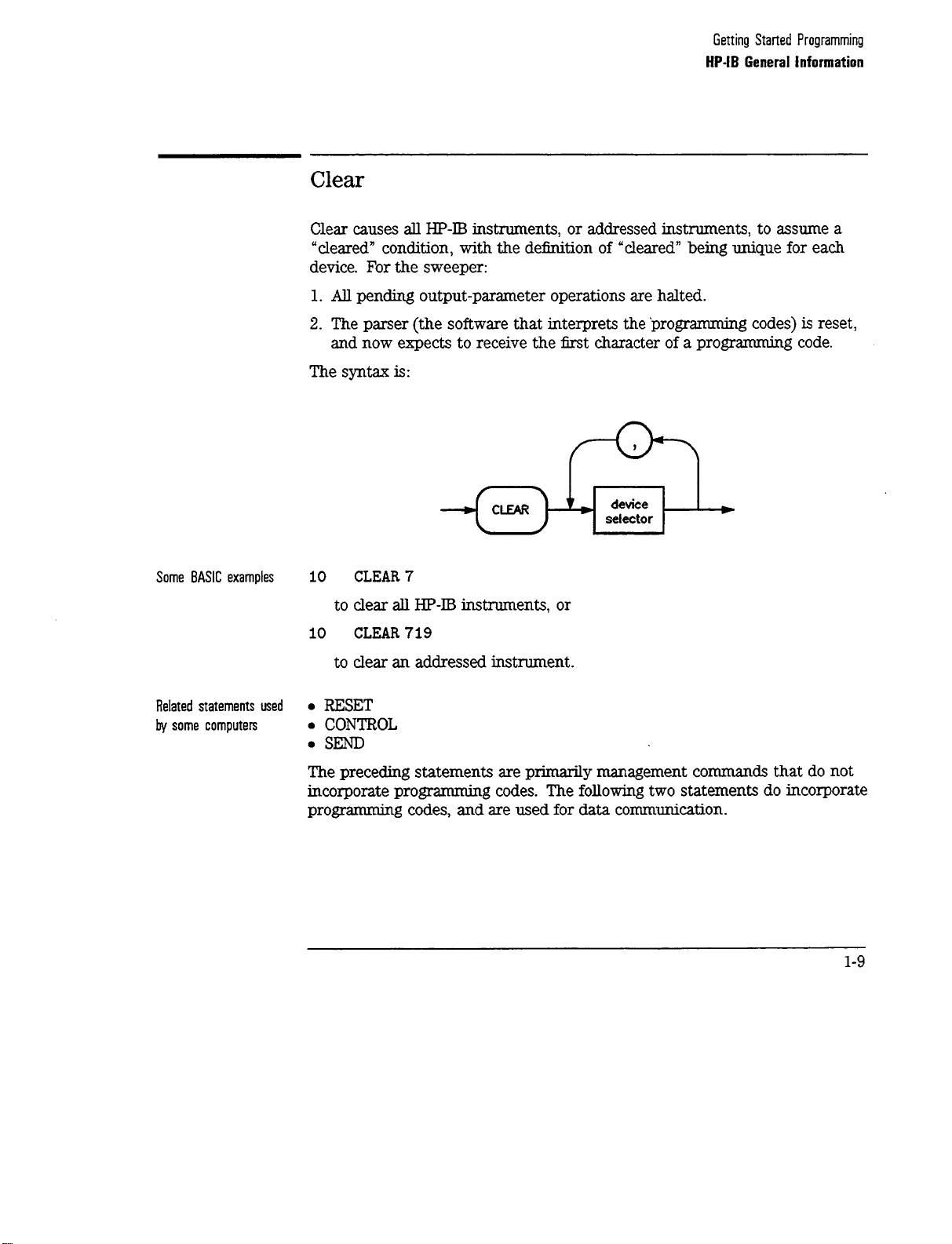
Clear
Remote/Local Changes
Service Request
Status Byte
Status Bit
Pass Control
Abort
Interface Function Codes
HP 83750 Series Status Byte Descriptions
. . . . . . . . .
Compatibility Guide
....................
........................
...................
....................
...................
...................
..................
......................
.......................
.......................
...................
.....................
.....................
....................
.......................
. . . . . . . . . . . .
. . . . .
............
............
............
............
............
............
............
............
............
............
............
. . . . . . . . . . . .
...........
..........
...............
.................
.................
................
.............
................
...............
......
2-82
2-82
2-83
2-83
2-83
2-84
2-84
2-84
2-85
2-86
2-86
2-87
2-87
2-88
3-1
3-l
3-1
3-2
3-2
3-3
3-3
3-4
3-4
3-5
3-6
3-13
3-13
3-14
3-14
3-15
3-22
3-22
3-23
3-24
3-24
3-24
3-24
3-25
3-26
Contents-10
Page 19

4. Error Messages
:ERRor?
SYSTem:ERRor
The Error/Event Queue
Error numbers
No Error
SCPI Error Messages
Error Message Description
Example Error
Command Error
......................
Execution Error
Device-Specific Error
Query
Instrument Specific Error Messages
Block Transfer Errors
Bus Control Errors
Parsing and Compatibility Errors
Diagnostics and Self-Test Errors
Internal Hardware Errors
Hardware Configuration Errors
Calibration Routine Errors
Loops Unlocked Errors
Miscellaneous Hardware Dependent Errors
Error
................
...............
...................
................
.............
.................
..................
..................
................
....................
.........
...............
................
..........
...........
..............
...........
.............
...............
......
4-3
4-4
4-5
4-5
4-6
4-6
4-6
4-8
4-14
4-20
4-22
4-24
4-24
4-25
4-26
4-29
4-33
4-33
4-34
4-36
4-37
5. SCPI Conformance Information
SCPI Conformance . . . . . . . . . . . . . . . . .
Index
5-3
Contents-l
1
Page 20
Figures
l-l. SCPI Command Types
l-2.
A Simplified Command Tree
l-3.
Proper Use of the Colon and Semicolon
l-4. Simplified SWEep
l-5. Voltage Controlled Oscillator Test
l-6.
Simplified Program Message Syntax
l-7.
SCPI
l-8. Simpliiied
l-9.
Simplified Response Message Syntax
l-10.
Generalized Status Register Model
l-11.
Typical Status Register Bit Changes
l-12.
Status Registers
l-
13. The TRIG Trigger Configuration
l-14. Simplified Trigger Model
2-l. Instrument Trigger Model
Simplified
Common Command Syntax
Command Tree
Subsystem Command Syntax
.....................
..................
.................
Tables
...............
..........
.............
.............
............
........
...........
............
.............
............
..............
................
l-20
l-21
l-23
l-24
l-33
l-37
l-38
l-39
l-40
l-69
l-71
l-78
l-81
l-82
2-34
l-l. Command Table
l-2.
SCPI Data Types
l-3.
Sample Sweeper Commands
2-l.
Interactions between Dwell, Sweep Time, and Points. _ _ _ .
2-2. HP 83750 SCPI Sweep Mode Programming Table
2-3. Sweeper Key Codes
5-l. SCPI Conformance
Contents-12
.....................
....................
...............
...................
....................
......
l-25
l-41
l-49
2-64
2-71
2-80
5-4
Page 21

1
Getting Started
Programming
Page 22
Getting Started Programming
HP-& the Hewlett-Packard Interface Bus, is the instrument-to-instrument
communication system between the sweeper and up to 14 other instruments.
Any instrument having
including non-HP instruments that have
or
‘IEC-625”
electricahy equivalent although
portion of the manual specifically describes interfacing the sweeper to a
computer.
capability (these are common generic terms for
HP-II3
capability
W-625
can
be interfaced to the sweeper,
“GPIB,” “IEEE-488, ’
uses a unique connector). This
“ANSI
HP-E!;
MCl.
all are
1,”
The first part of this section provides general
the Standard Commands for Programmable Instruments language
introduced, and example programs are given.
HP-LB
information. Later,
(SCPI)
is
l-2
Page 23

HP-IB General Information
Interconnecting Cables
The Installation Guide shows the sweeper rear-panel
and suitable cables, and describes the procedures and limitations for
interconnecting instruments. Cable length restrictions, also described in the
Installation Guide, must be observed to prevent transmission line propagation
delays that might disrupt HP-IB timing cycles.
HIP-B
connector
Instrument Addresses
Each in.stnunent in an HP-IB network must have a unique address, an integer
ranging in value from 0 to 30. The default address for the sweeper is 19, but
this can be changed using the
(m) [m)
keys or rear panel switch.
1-3
Page 24
Getting Started Programming
HP-IB General Information
Listener
Talker
Controller
HP-B
An HP-IB instrument is categorized as a ‘listener, n “talker, * or “controller,
Instrument Nomenclature
n
depending on its current function in the network.
A listener is a device capable of receiving data or commands from other
instruments. Any number of instruments in the HP-IB network can be
listeners simultaneously.
A talker is a device capable of transmitting data or commands to other
instruments.
‘lb
avoid confusion, an HP-IB system
allows
only one device at a
time to be an active talker.
A controller is an instrument, typically a computer, capable of managing the
various HP-IB activities. Only one device at a time can be an active controller
Programming the Sweeper
The sweeper can be controlled entirely by a computer (although the line
POWER switch must be operated manually). Several functions are possible
only by computer (remote) control. Computer programming procedures for
the sweeper involve selecting an
the
specific
sweeper (SCPI, Analyzer) programming codes to that statement
to achieve the desired operating conditions. The programming codes can be
categorized into two groups: Those that mimic front panel keystrokes; and
those that are unique, and have no front panel equivalent.
HP-IE3
command statement, then adding
In the
progmmming
explanations that
follow,
specific examples are included
that are written in a generic dialect of the BASIC language. BASIC was
selected because the majority of HP-IB computers have BASIC language
capability. However, other languages can also be used.
l-4
Page 25

Getting Started Programming
HP-IB General
lnfomation
HP-II3
Command statements form the nucleus of
understood by all mstruments in the network and, when combined with
the
communication instructions for the system.
An explanation of the eight fundamental command statements follows.
However, some computers use a slightly different terminology, or support an
extended or enhanced version of these
explanations as a starting point, but for detailed information consult the
BASIC language reference manual, the
manual for the particular computer used.
Syntax drawings accompany each statement: All items enclosed by a circle or
oval are computer specific terms that must be entered exactly as described;
items enclosed in a rectangular box are names of parameters used in the
statement; and the arrows indicate a path that generates a valid combination
of statement elements.
Command Statements
progmmming
language codes, they provide all management and data
HP-D
programming; they are
conunands.
I/O
programming guide, and the
Consider the following
HP-IB
l-5
Page 26

Page 27

Getting Started Programming
HP-IB General lnfomation
Remote
Remote causes an instrument to change from local control to remote control.
In remote control, the front panel keys are disabled (except for the
key and the POWER switch), and the REMOTE Annunciator is lighted. The
syntax is:
[E?Kj
Some BASIC examples
where the device selector is the address of the instrument appended to the
HP-E3
port number. Typically, the
HP-II3
port number is 7, and the default
address for the sweeper is 19, so the device selector is 719.
10
REMOTE7
which prepares
all HP-II3
instruments for remote operation (although
nothing appears to happen to the instruments until they are addressed to
talk), or
10
REMOTE719
which affects the HP-B instrument located at address 19, or
10
REMOTE719,
which effects four instruments that
721, 726, 715
have addresses
19, 21,
26,
and
15.
1-7
Page 28
Getting Started Programming
HP-IB General Information
-
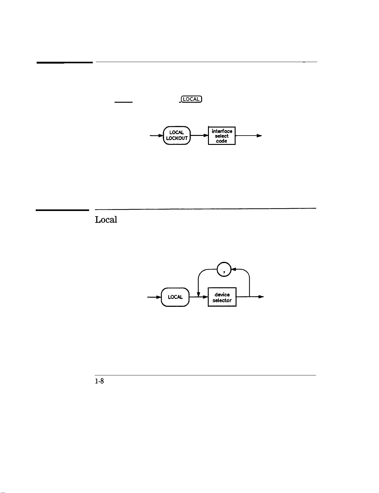
Local Lockout
Local Lockout can be used in conjunction with REMOTE to disable the front
panel (LOCAL) key. With the
hard reset by the POWER switch) can restore local control. The syntax is:
(ml
key disabled, only the controller (or a
A BASIC example
10
20
REMOTE
719
LOCALLOCKOUT
interface
sect -
code
w
Local is the complement to REMOTE, causing an instrument to return to local
control with a fully enabled front panel. The syntax is:
Some BASIC examples
LOCAL 7
10
which effects all instruments in the network, or
LOCAL 719
10
for an addressed instrument (address 19).
l-8
Page 29
Page 30

Getting Started Programming
HP-IB General Information
output
Output is used to send function commands and data commands from the
controller to the addressed instrument. The syntax is:
where USING is a secondary command that formats the output in a particular
way, such as a binary or ASCII representation of numbers. The USING
command is followed by “image items” that precisely define the format of the
output; these image items can be a string of code characters, or a reference
to a statement line in the computer program. Image items are explained in
the
programming
codes where they are needed. Notice that this syntax
is
virtually identical to the syntax for the ENTER statement that follows.
l-10
Page 31

Page 32

Getting Started Programming
HP-18
General Information
Enter
Enter is the complement of OUTPUT, and is used to transfer data from the
addressed instrument to the controller. The syntax is:
ENTER is always used in conjunction with OUTPUT, such as:
100
OUTPUT 719; ‘I . . . programming codes . . .
110
ENTER 719; ” . . . response data.. .
”
”
ENTER statements are commonly formatted, which requires the secondary
command USING and the appropriate image items. The most-used image
items involve end-of-line (end or identify) suppression, binary inputs, and
literal inputs.
Example
100 EXTER719USING ‘I#, B”;
suppresses the EOI sequence
are to be filled with binary
100
ENTER
719 USING
I’#, 123A”
A, B, C
(#),
and indicates that variables A, B, and C
(B)
data. As another example,
; A$
suppresses EOI, and indicates that string variable A$ is to be filled with
123 bytes of literal data
(123A).
1-12
Page 33

Getting Started Programming
HP-IB General Information
NOTE
Be careful when using byte-counting image specifiers. If the requested number of bytes does not
match the actual number available, data might be lost, or the program might enter an endless wait
state.
The suppression of the EOI sequence is frequently necessary to prevent a
premature termination of the data input. When not specified, the typical
EOI termination occurs when an ASCII LF (line feed) is received. However,
the LF bit pattern could coincidentally occur randomly in a long string of
binary data, where it might cause a false termination. Also, the bit patterns
for the ASCII CR (carriage return), comma, or semicolon might cause a false
termination. Suppression of the EOI causes the computer to accept all bit
patterns as data, not conunands, and relies on the HP-IB EOI (end or identify)
line for correct end-of-data termination.
Related statements used
by some computers
. CONVERT
. IMAGE
l
IOBUFFER
l
ONTIMEOUT
. SET TIMEOUT
. TRANSFER
This completes the HP-IB Command Statements subsection. The following
material explains the SCPI programming codes, and shows how they are used
with the OUTPUT and ENTER HP-IB command statements.
1-13
Page 34

Getting Started with SCPI
This section of chapter 1 describes the use of the Standard Commands for
Programmable Instruments language
SCPI commands in general. The instrument command summary
lists the specific commands available in the instrument. This section presents
only the basics of SCPI. If you want to explore the topic in greater depth, see
the paragraph titled, “Related Documents.
(SCPl).
This section explains how to use
n
in Chapter 5
1-14
Page 35

Definitions of Terms
You need a general understanding of the terms listed below before you
continue.
controller
instrument
program
message
response
message
command
A controller is any computer used to communicate with a
SCPI instrument. A controller can be a personal computer,
a minicomputer, or a plug-in card in a card cage. Some
intelligent instruments can also function as controllers.
An instrument is any device that implements SCPI. Most
instruments are electronic measurement or stimulus devices,
but this is not a requirement. Similarly, most instruments
use an
concepts apply regardless of the instrument function or the
type of interface used.
A program message is a combination of one or more
properly formatted SCPI commands. Program messages
always go from a controller to an instrument. Program
messages tell the instrument how to make measurements
and output signals.
A response message is a collection of data in
formats. Response messages always go from an instrument
to a controller or listening instrument. Response messages
tell the controller about the internal state of the instrument
and about measured values.
A command is an instruction in SCPI. You combine
commands to form messages that control instruments. In
general, a command consists of mnemonics (keywords),
parameters, and punctuation.
HP-D3
interface for communication. The same
spetic
SCPI
query
A query is a special type of command. Queries instruct the
instrument to make response data available to the controller.
Query mnemonics always end with a question mark.
1-15
Page 36

Getting
Staned
Programming
Definitions of Terms
Standard Notation
This section uses several forms of notation that have specific meaning.
Command Mnemonics
Angle Brackets
Many commands have both a long and a short form, and you must use either
one or the other (SCPI does not accept a combination of the two). Consider
the
FREQuency
command,for example. The short form is FREQ and the long
form is FREQUENCY (this notation style is a shorthand to document both the
long and short form of commands). SCPI is not case sensitive, so
fREquEnCy
is just as valid as FREQUENCY, but FREQ and FREQUENCY are the only valid
forms of the
FREQuency
command.
Angle brackets indicate that the word or words enclosed represent something
other than themselves. For example,
character with the decimal value 10.
asserted on the
HP-II3
interface. Words in angle brackets have much more
<new
line> represents the ASCII
Siruilarly, <‘END>
means that EOI is
rigidly defined meaning than words used in ordinary text. For example, this
section uses the word “message” to talk about messages generally. But the
bracketed words <program message> indicate a precisely
dellned
element of
SCPI. If you need them, you can find the exact definitions of words such as
<program message> in a syntax diagram.
How to Use Examples
It is important to understand that progr
amming
with SCPI actually requires
knowledge of two languages. You must know the programming language of
your controller (BASIC, C, Pascal) as well as the language of your instrument
(SCPI). The semantic requirements of your controller’s language determine
how the SCPI commands and responses are handled in your application.
1-16
Page 37

Getting Started Programming
Definitions of Terms
Command Examples
Response Examples
Command examples look like this:
:FREQuency:CW?
This example tells you to put the string :
FEEQuency
: CW? in the output
statement appropriate to your application programming language. If you
encounter problems, study the details of how the output statement handles
message terminators such as
<new
line>. If you are using simple OUTPUT
statements in HP BASIC, this is taken care of for you. In HP BASIC, you type:
OUTPUT
Source;“:FREQuency:CW?”
Command examples do not show message terminators because they are used
at the end of every program message.
“Details of Commands and Responses,
n
discusses message terminators in more detail.
Response examples look like this:
1.23
These are the characters you would read from an instrument after
sending a query command. To actually pull them from the instrument into
the controller, use the input statement appropriate to your application
programming language. If you have problems, study the details of how the
input statement operates. In particular, investigate how the input statement
handles punctuation characters such as comma and semicolon, and how it
handles
<new
line> and EOI. ‘lb enter the previous response in HP BASIC,
you type:
ENTER
Source;CW,frequency
Response examples do not show response message terminators because
they are always <new line>
<-END>.
These terminators are typically
automatically handled by the input statement. The paragraph titled “Details
of Commands and Responses” discusses message terminators in more detail.
1-17
Page 38

Essentials for Beginners
This subsection discusses elementary concepts critical to &st-time users of
SCPI. Read and understand this subsection before going on to another. This
subsection includes the following topics:
Program and Response
Messages
Subsystem Command Trees
Subsystem Command Tables
Reading Instrument Errors
Example Programs
These paragraphs introduce the basic types
of messages sent between instruments and
controllers.
These paragraphs describe the tree structure
used in subsystem commands.
These paragraphs present the condensed
tabular format used for documenting
subsystem commands.
These paragraphs explain how to read
and print an instrument’s internal error
messages.
These paragraphs contain two simple
measurement programs that illustrate basic
SCPI programming principles.
1-18
Page 39

Getting Started Programming
Essentials for Beginners
Program and Response Messages
To understand how your instrument and controller communicate using
SCPI, you must understand the concepts of program and response messages.
Program
instrument. Conversely,
the instrument to the controller. Program messages contain one or more
commands, and response messages contain one or more responses.
The controller may send commands at any time, but the instrument sends
responses only when
command used to instruct the instrument to send a response message is the
QZUZQ.
measured values or internal instrument settings. Any internal setting that can
be programmed with SCPI can also be queried.,
messages
are the formatted data sent from the controller to the
response
specifically
messages are the formatted data sent from
instructed to do so. The special type of
All query mnemonics end with a question mark. Queries return either
Forgiving listening and
Precise Talking
Tvpes
of Commands
SCPI uses the concept of forgiving listening and precise talking outlined in
IEEE 488.2.
Rxgiting
listening means that instruments are very flexible in accepting
various command and parameter formats. For example, the sweeper accepts
either
:POWer:STATe ON
R-&e talk%ng
means that the response format for a particular query is
or
:POWer:STATe
ItoturnRFoutputon.
always the same. For example, if you query the power state when it is on
(using
previously sent :
Commands
:POWer:
STATe?), the response is always I,
POWer
: STATe 1 or
:POWer
: STATe ON.
regardless of whether you
can be separated into two groups, common commands and
subsystem commands.
Common comwzun&
are generally not measurement related. They are
used to manage macros, status registers, synchronization, and data storage.
Common commands are easy to recognize because they all begin with an
asterisk, such as
*IDN?, *OPC, and
*RST.
Common commands are defined by
IEEE 488.2.
3&.@em
commands include all measurement functions and some general
purpose functions. Subsystem commands are distinguished by the colon used
3
between keywords,
asin :FREQuency:CW..
Each command subsystem is a
1-19
Page 40

Getting Started Programming
Essentials for Beginners
set of conunands that roughly corresponds to a functional block inside the
instrument. For example, the
POWer
subsystem contains commands for power
generation, while the STATUS subsystem contains commands for accessing
status registers.
*
RST
*
IDN?
: MEAS : VOLT?
:FREQ 1KHz
cg410
Figure l-l. SCPI Command Types
The remaining paragraphs in this subsection discuss subsystem commands in
more detail. Remember, some commands are implemented in one instrument
and not in another, depending on its measurement function.
l-20
Page 41

Subsystem Command Trees
Getting Started Programming
Essentials for Beginners
The Command Tree
Structure
Paths Through the
Command Tree
Most programming tasks involve subsystem commands. SCPI uses a
hierarchical structure for subsystem commands similar to the file systems on
most computers. In SCPI, this command structure is called a command
root
level 1
I
BB
AA
I
cc DD
tree.
d-l
level 2 EE FF GG
Figure 1-2. A Simplified Command Tree
In the command tree shown in Figure
is the root commww!, or simply the root. Notice that you must follow a
particular
to access the GG command, you must follow the path AA to BB to GG.
lb access commands in di8erent paths in the command tree, you must
understand how an instrument interprets commands. A special part of the
instrument firmware, a
The parser breaks up the message into component commands using a set of
rules to determine the command tree path used. The parser keeps track of
the current path, the level in the command tree where it expects to find the
next
appear in different paths. The particular path you use determines how the
keyword is interpreted. The following rules are used by the parser:
puth
command
to reach lower level subcommands. For example, if you wish
panser,
you send. This is important because the same keyword may
decodes each message sent to the instrument.
l-2,
the command closest to the top
HH
JJ
1-21
Page 42

Getting Started Programming
Essentials for Beginners
l
RxwrOnandReset
After power is cycled or after
*RST,
the current path is set to the root.
A message terminator, such as a <new line> character, sets the current
path to the root. Many progr
amming
languages have output statements
that send message terminators automatically. The paragraph titled, “Details
of Commands and Responses, ’ discusses message terminators in more
detail.
When it is between two command mnemonics, a colon moves the current
path down one level in the command tree. For example, the colon in
MEAS
is the
: VOLT
tit
speties
that VOLT is one level below
character of a command, it
spec3ies
MEAS.
When the colon
that the next command
mnemonic is a root level command. For example, the colon in : INIT
specifies that INIT is a root level command.
A semicolon separates two commands in the same message without
changing the current path.
Whitespace characters, such as <tab> and <space>, are generally ignored.
There are two important exceptions. Whitespace inside a keyword, such
as
:FREQ
uency, is not allowed. You must use white space to separate
parameters from commands. For example, the <space> between
6.2 in the command :
not
tiect
the current path.
POHer
:
LEVe16.2
is mandatory. Whitespace does
LEVel
and
l
Cbmmas
lf a command requires more than one parameter, you must separate
adjacent parameters using a comma. Commas do not
affect
the current
path.
l
comrnOncOmmands
Common commands, such as
*RST,
are not part of any subsystem. An
instrument interprets them in the same way, regardless of the current path
setting.
l-22
Page 43

Getting Started Programming
Essentials for Beginners
I
BB
I
EE
AkBB:EE;FF;GG
A4zBB:EE; A4zDD:JJ
FF
Figure
I
cc
I
GG
l-3.
Proper Use of the Colon and Semicolon
I
HH
I
DD
I
JJ
R Sets current path
0
to ROOT
N NO change to
0
current path
Figure l-3 shows examples of how to use the colon and semicolon to
navigate efficiently through the command tree. Notice how proper use of the
semicolon can save typing.
Sending this message:
:AA:BB:EE; FF; GG
Is the same as sending these three messages:
:AA:BB:EE
:AA:BB:FF
:AA:BB:GG
l-23
Page 44

Getting Started Programming
Essentials for Beginners
Subsystem Command
These paragraphs introduce a more complete, compact way of documenting
subsystems using a tabular format. The command table contains more
information than just the command hierarchy shown in a graphical tree. In
particular, these tables list command parameters for each command and
response data formats for queries. To begin this exploration of command
tables, consider a simplified
graphical and tabular formats.
SWEep
SWEep
‘Ihbles
subsystem for the sweeper in both the
I
I
DWELI
AUTO
Figure
GENeration
POlNt RELative
l-4.
Simplified SWEep Command Tree
MANuaI
l-24
Page 45

Table
1-l.
Command Table
Getting Started Programming
Essentials for Beginners
Reading the Command
Table
Parameter
Two
:SWEep
:OWEU
:GENeration
:MANual
Command
:AUTO
:POINt
[:RELativel
state
Parameters
BooieanJONCE
Note the three columns in the command table labeled Command, Parameters,
and
parameter Type.
Commands closest to the root level are at the top of
the table. Commands in square brackets are implied commands, which are
discussed in later paragraphs. If a command requires one or more parameters
in addition to the keyword, the parameter names are listed adjacent to the
command. Parameters in square brackets are optional parameters, which
are discussed in later paragraphs. If the parameter is not in square brackets,
it is required and you must send a valid setting for it with the matching
command. The parameter type is listed adjacent to each named parameter.
1-25
Page 46

Getting Started Programming
Essentials for Beginners
More About Commands
Query and Event
Commands
implied Commands
Optional Parameters
Because you can query any value that you can set, the query form of each
command is not shown explicitly in the command tables. For example,
the presence of the sweeper : SWEep :
: SWEep :
DUELl?
also exists. If you see a table containing a command ending
DWELl
command implies that a
with a question mark, it is a query only command. Some commands are
events, and cannot be queried. An event has no corresponding setting if it
causes something to happen inside the instrument at a particular instant. For
example, :
Because it is an event, there is no query form of :
Implied
INITiate
: IMMediate causes a certain trigger sequence to initiate.
INITiate
: IMMediate.
commands appear in square brackets in the command table. If you
send a subcommand immediately preceding an implied command, but do
not send the implied command, the instrument assumes you intend to use
the implied command, and behaves just as if you had sent it. Note that this
means the instrument expects you to include any parameters required by
the implied command. The following example illustrates equivalent ways to
program the sweeper using explicit and implied
commands.
Example sweeper commands with and without an implied commands:
: SWEep :
: SWEep :
MANual
MANual
:
RELative
6
6
u&w explicit commands
using implied wmmands
Optional parameter names are enclosed in square brackets in the command
table. If you do not send a value for an optional parameter, the instrument
chooses a default value. The instrument’s command dictionary documents the
values used for optional parameters.
l-26
Page 47

Getting Started Programming
Essentials for Beginners
Program Message Examples
The following parts of the sweeper SCPI command set will be used to
demonstrate how to create complete SCPI program messages:
:
FRF.Quency
C:CWl
:MULTiplier
:STATE
: POWER
[:LEVEL]
Example 1
Example 2
"FREQuency:CW
5 GHZ;
MULTiplier2"
The command is correct and will not cause errors. It is equivalent to
sending:
"FREQuency:CW
"FREQuency5
5 GHZ;
GHZ;
:FREQuency:MULTiplier2".
MULTiplier2"
This command results in a command error. The command makes use of
the default
the current path position. Since there is no command
[:CWJ
node. When using a default node, there is no change to
WULT”
at the root,
an error results. A correct way to send this is:
“F&Q 5 GHZ; FREQ
:I4ULT 2”
or as in example 1.
l-27
Page 48

Getting Started Programming
Essentials for Beginners
Example 3
Example 4
"FREQuency:MULTiplier2;
MULTiplier:STATEON;
FREQuency:CW5
GHZ"
This command results in a command error. The
F’REQ:CW
portion of the
command is missing a leading colon. The path level is dropped at each
colon until it is in the
F’REQ:h3UI.T
subsystem. So when the
F’REQ:CW
command is sent, it causes confusion because no such node occurs in the
F’REQ:MULT
subsystem. By adding a leading colon, the current path is
reset to the root. The corrected command is:
"FREQuency:MULTiplier2;
5
GHZ".
"FREQ5
GHZ;
POWER4DBM"
Notice that in this example the keyword short
command is correct. It utilizes the default nodes of
MULTiplier:STATE
ON;
formis
[:Cw]
:FFEQuency:CW
used. The
and [LEVEL].
Since default nodes do not affect the current path, it is not necessary to
use a leading colon before POWER.
l-28
Page 49

Parameter Types
Getting Started Programming
Essentials for Beginners
Numeric Parameters
As you saw m the example command table for
SWEep,
there are several
types of parameters. The parameter type indicates what kind of values are
valid instrument settings. The most commonly used parameter types are
numeric, extended numeric, discrete, and Boolean. These common types are
discussed briefly in the following paragraphs. The paragraph titled “Details of
Commands and Responses” explains all parameter types in greater depth.
Numeric parameters are used in both subsystem commands and common
commands. Numeric parameters accept all commonly used decimal
representations of numbers including optional signs, decimal points, and
scientific notation. If an instrument accepts only specifk numeric values, such
as integers, it automatically rounds numeric parameters to fit its needs.
Examples of numeric parameters:
100
100.
-1.23
4.56e<space>3
-7.89E-01
+256
.5
no
decinml
point required
ji-actimal digits optimal
leading signs
space allowed am e in
we either E or e in
allowed
eqwnmt.s
exponentials
leading + allowed
digits
lq? of
decimal point optional
Examples of numeric parameters in commands:
100 OUTPUT @Source; ”:
110
OUTPUT
@Source; “:POWer LEVel
FREQuency
:
STARt
-5”
l.OE+09”
l-29
Page 50

Getting
Staned
Programming
Essentials for Beginners
Extended Numeric
Parameters
Most measurement related subsystems use
IZZWKJ&
numeric parameters to
specify physical quantities. Extended numeric parameters accept all numeric
parameter values and other special values as well. AU extended numeric
parameters accept
MAXimum
and
MINimum
as values. Other special values,
such as UP and DOWN may be available as documented in the instrument’s
command summary. Some instruments also let you to scud engineering units
as
sufhxes
lists the
to extended numeric parameters. The SCPI
sulZxes
available, if any. Note that extended numeric parameters are
Comman
d Summary
not used for common commands or STATUS subsystem commands.
Examples of extended numeric parameters:
ang
100.
-1.23
simple numeric values
largest valid setting
4.56e<space>3
-7.89E-01
+256
.5
MAX
MIN
valid setting nearest negative
iqjinity
Examples of extended numeric parameters in commands:
100 OUTPUT @Source ; ‘I :
FREQuency
: STOP MAX”
l-30
Page 51

Getting Started Programming
Essentials for Beginners
Discrete Parameters
Boolean Parameters
Use discrete parameters to program settings that have a
values. Discrete parameters use mnemonics
to
represent each valid setting.
finite
number of
They have a long and a short form, like command mnemonics. You can use
mixed upper and lower case letters for discrete parameters.
Examples of discrete parameters:
INTernal level
DIODe
PMETer
MMHead
internally
level using an
level using an
external
-1powermeter
diode
Level using a mm-wave source module
Examples of discrete parameters in commands:
100 OUTPUT
110 OUTPUT
QSource;”
@Source;”
:POWer:ALC:SOUHce INT”
:POWer:ALC:SOUHce mmh”
Although discrete parameters values look like command keywords, do not
confuse the two. ln particular, be sure to use colons and spaces properly.
Use a colon to separate command mnemonics from each other. Use a
space to separate parameters from command mnemonics.
Boolean parameters represent a single binary condition that is either true or
false. There are only four possible values for a Boolean parameter.
Examples of Boolean parameters:
ON
OFF
1
0
Boolean TRUE,
upperher case
Boolean FALSE,
Boolean TRUE
Boolean FALSE
u.er/lozuer
allowed
case allowed
Examples of Boolean parameters in commands:
100 OUTPUT @Source ; I’ : FM :
110 OUTPUT QSource;“:AM:STATe
STATe
On”
I”
1-31
Page 52

Getting
Staned
Programming
Essentials for Beginners
Reading Instrument Errors
When debugging a program, you may want to know if an instrument error
has occurred. Some instruments can display error messages on their front
panels. If your instrument cannot do this, you can put the following code
segment in your program to read and display error messages.
10
!
20 ! The rest of your
30 ! variable declarations
40
!
50
DIM
Err_msg$[751
60
INTEGER
70
!
80 ! Part of your program
90 ! that generates errors
100
!
110
!
200
REPEAT
210
220
230
240
250
260
270
OUTPUT
! Query instrument error
ENTER
! Read error #, message
PRINT
! Print error message
UNTIL Err,num = 0
280 ! Repeat until no errors
290
!
300 ! The rest of your program
310
!
Err,num
@Box;":SYST:ERR?"
QBox;Err,num,Err,msg$
Err,num,Err,msg$
l-32
Page 53

Getting Started Programming
Essentials for Beginners
Exarnple Programs
The following is an example program using SCPI compatible instruments. The
example is written in HP BASIC.
This example is a stimulus and response application. It uses a source and
counter to test a voltage controlled oscillator.
This example demonstrates how several SCPI instruments work together
to perform a stimulus/response measurement. This program measures the
linearity of a voltage controlled oscillator (VCO). A VCO is a device that
outputs a frequency proportional to an input signal level.
how the hardware is configured.
Unit Under Test .
F’igure
1-5 shows
Example Program
20
30
40
50
60
70
80
Stimulus
source
0-5OOmV
Figure 1-5. Voltage Controlled Oscillator Test
!
INTEGER
DIM Id$
First,Last,Testpoint,Dummy
[701
ASSIGN @Stimulus TO 717
ASSIGN @Response TO 718
!
First=0
c
vco
HP
BASIC
Controller
e
Response
Counter
l-33
Page 54

Getting Started Programming
Essentials for Beginners
90
100
110
120
130
140
150
160
170
180
190
200
210
220
230
240
250
260
270
280
290
300
310
320
330
340
350
360
370
380
390
400
410
420
430
440
450
460
470
480
Last=100
!
CLEAR @Stimulus
CLEAR @Response
!
OUTPUT
OUTPUT
QStimulus;"*RST"
OResponse;"*RST"
!
PRINT "Voltage Controlled Oscillator Test"
PRINT
!
PRINT "Source Used .
OUTPUT
ENTER
OStimulus;"*IDN?"
QStimulus;Id$
.."
PRINT Id$
PRINT
!
PRINT "Counter Used .
OUTPUT
ENTER
OResponse;"*IDN?"
OResponse;Id$
.."
PRINT Id$
PRINT
!
OUTPUT
QStimulus;":OUTPUT
ON"
!
PRINT
PRINT "INPUT
PRINT
II--------,-II II------------II
[mv]","OUTPUT CkIizl”
,
PRINT
!
FOR
Testpoint=First
OUTPUT
ENTER
OUTPUT
ENTER
PRINT
QStimulus;":SOURCE:VOLT
QStimulus;Dummy
OResponse;":MEAS:FREQ?"
OResponse;Reading
Testpoint,Reading/lOOO
TO Last
";VAL$(Testpoint/lOOO);";*OPC?"
NEXT Testpoint
!
OUTPUT
QSource;":OUTPUT
OFF"
END
l-34
Page 55

Getting Started Programming
Essentials for Beginners
Program Comments
Lines 20 to 70: Declare variables and
I/O
paths for instruments.
I/O
paths let
you use a name for an instrument m OUTPUT and ENTER statements, instead
of a numeric address.
80 to 100:
110 to 130:
140 to 160:
170 to 190:
200 to 310:
Assign values to the input test limits in
Clear the instrument
HP-LB
interfaces.
Reset each instrument to a known measurement state.
Ftrint
the test report title.
Query measurement instruments’
identikations
mV.
for test
traceability.
320 to 330:
340 to 380:
390 to 460:
Connect the source output signal to the output terminals.
Print results table header.
This is the main measurement loop. Line 400 contains two
commands. :
*OPC?
is used to signal that the preceding command has
SOUFtce
: VOLT sets the output level of the source.
finished executing. To make an accurate measurement, the
source output must be allowed to settle. When the output has
settled,
*OPC?
places a 1 in the source Output Queue. The
program waits at line 410 until the 1 returned by *OPC? is
entered.
Note that following each OUTPUT containing a query is
an
ENTER to retrieve the queried value. If you do not use paired
OUTPUTS and
ENTERs,
you can overwrite data in the instrument
Output Queue and generate instrument errors.
470 to 480:
Disconnect output terminals of the instruments
from
the unit
under test, and end the program. All HP BASIC programs must
have
END
as the last statement of the main program.
l-35
Page 56

Details of Commands and Responses
This subsection describes the syntax of SCPI commands and responses. It
provides many examples of the data types used for
response data. The following topics are explained:
Program Message These paragraphs explain how to properly construct
Syntax
the messages you send from the computer to
instruments.
conkand
parameters and
Response Message
SYnW
SCPI Data Types
These paragraphs discuss the format of messages sent
from instruments to the computer.
These paragraphs explain the types of data contained
in program and response messages.
l-36
Page 57

Getting Started Programming
Details of Commands and Responses
Program Message Syntax
These program messages contain commands combined with appropriate
punctuation and program message terminators.
)
subsystem command
common command
NOTES:
<new line>
AEND
=
<new line>
= ASCII character decimal 10
EOI asserted concurrent with last byte
Figure 1-6. Simplified Program Message Syntax
AEND
As Figure l-6 shows, you can send common commands and subsystem
commands in the same message. If you send more than one command in the
same message, you must separate them with a semicolon. You must always
end a program message with one of the three program message terminators
shown in Figure 1-6. Use
as the program message terminator. The word
asserted on the
HP-D3
interface at the same time the preceding data byte is
<new
line>,
<-END>,
or
<new
<-END>
line>
<-END>
means that EOI is
sent. Most progmmming languages send these terminators automatically.
For example, if you use the HP BASIC OUTPUT statement, <new line> is
automatically sent after your last data byte. If you are using a PC, you can
usually configure the system to send whatever terminator you specify.
l-37
Page 58

Getting Started Programming
Details of Commands and Responses
SCPI Subsystem Command Syntax
NOTE
=
SP
Figure
white
w. ASCil
I-7.
SCPI Simplified Subsystem Command Syntax
characters
O,,
to
9,0
and
ll,,
to
32,,
As Figure l-7 shows, there must be a <space> between the last command
mnemonic and the first parameter in a subsystem command. This is one of
the few places in SCPI where <space> is required. Note that if you send
more than one parameter with a single command, you must separate adjacent
parameters with a comma. Parameter types are explained later in this
subsection.
1-38
Page 59

Common Command Syntax
mnemonic
NOTE
SP - white space, ASCII characters
Figure 1-8. Simplified Common Command Syntax
0,0
to
Getting Started Programming
Details of Commands and Responses
9,0
and
11,0
to
32,0
As with subsystem commands, use a <space> to separate a command
mnemonic from subsequent parameters. Separate adjacent parameters with
a
comma. Parameter types are explained later in this subsection.
l-39
Page 60

Getting Started Programming
Details of Commands and Responses
Response Message Syntax
’
b
response data
Response messages can contain both commas and semicolons as separators.
When a single query command returns multiple values, a comma separates
each data item. When multiple queries are sent in the same message,
the groups of data items corresponding to each query are separated by a
semicolon. For example, the fictitious query :
return a response message of:
Response data types are explained later in this subsection. Note that
<new lineXXND>
Figure
l-9.
Simplified Response Message Syntax
QUERYI?
<datal>,<datal>;<datti>,<data2>
is always sent as a response message terminator.
:
QUE3Y2?
*
might
l-40
Page 61

Getting Started Programming
Details of Commands and Responses
SCPI Data Types
These paragraphs explain the data types available for parameters and
response data. They list the types available and present examples for each
type. SCPI defines different data formats for use in program messages
and response messages. It does this to accommodate the principle of
forgiving listening and precise talking. Recall that forgiving listening means
instruments are flexible, accepting
formats. Precise talking means an instrument always responds to a particular
query in a
predefined,
rigid format. Parameter data types are designed to be
flexible in the spirit of forgiving listening. Conversely, response data types
are
de&ted
to meet the requirements of precise
Table
lFiiz&i
commands
l-2.4
CPI
~
Response
and parameters in various
talldng.
Data Types
Data Typw
Numeric
Extended Numeric
Non-decimal Numeric
~
Real or Integer
Integer
Discrete
Numeric Boolean
String
Definite length Block
Indefinite length Block
Octal
Binatv
Notice that each parameter type has one or more corresponding response
data types. For example, a setting that you program using a numeric
parameter returns either real or integer response data when queried.
Whether real or integer response data is returned depends on the instrument
used. However, precise talking requires that the response data type be clearly
defined for a particular instrument and query. The instrument command
1-41
Page 62

Getting Started Programming
Details of Commands and Responses
dictionary generally contains information about data types for individual
commands. The following paragraphs explain each parameter and response
data type in more detail.
Parameter Types
Numeric Parameters
Numeric parameters are used in both subsystem commands and common
commands. Numeric parameters accept all commonly used decimal
representations of numbers including optional signs, decimal points, and
scientific notation.
If an instrument setting programmed with a numeric parameter can only
assume a
finite
number of values, the instrument automatically rounds
the parameter. For example, if an instrument has a programmable output
impedance of 50 or 75 ohms, and you specified 76.1 for output impedance,
the value is rounded to 75. If the instrument setting can only assume integer
values, it automatically rounds the value to an integer. For example, sending
*ESE
10.123 is the same as sending
*ESE
10.
Examples of numeric parameters:
100
100.
-1.23
4.56e<space>3
-7.89E-01
+256
.5
no decimal point required
ji-acttim
digits
optional
leading signs allowed
space allowed
use either E or e in
a@er
e in
exponent~k
leading + allowed
digits
kg%
of
de&ml
point optional
exponentials
l-42
Page 63

Getting Started Programming
Details of Commands and Responses
Extended Numeric
Parameters
Most measurement related subsystems use extended numeric parameters to
specify physical quantities.
Ez.Zen&& numeric parameters accept all numeric
parameter values and other special values as well. All extended numeric
parameters accept
MAX&m
and
MINimum
as values. Other special values,
such as UP and DOWN may be available as documented in the instrument’s
command dictionary. Note that
MINimum
and
MAXimum
can be used to set or
query values. The query forms are useful for determining the range of values
allowed for a given parameter.
In some instruments, extended numeric parameters accept engineering unit
su%ixes
as part of the parameter value. Refer to the command summary to
see if this capability exists.
Note that extended numeric parameters are not used for
con-unon
commands
or STATUS subsystem commands.
Examples of extended numeric parameters:
100.
-1.23
any simple numeric
va&.es
largest valid setting
4,56e<space>3
-7.89E-01
+256
.5
MAX
MIN
-100
mV
valid setting nearest negative
negative 100 millivolts
iqfhity
l-43
Page 64

Getting
Started
Details of Commands and Responses
Programming
Discrete Parameters
Boolean Parameters
Use
discrete pcz?-ameters
to program settings that have a
finite
number of
values. Discrete parameters use mnemonics to represent each valid setting.
They have a long and a short form, just like command mnemonics. You can
used mixed upper and lower case letters for discrete parameters.
Examples of discrete parameters used with the
INTernal
EXTernal
NONE
intmnal~~
standard
-lfi@W@?=Y
no.l%pmcg standard,
standard
free run
ROSCiUator
mode
subsystem:
Although discrete parameters values look like command keywords, do not
confuse the two.
h-t
particular, be sure to use colons and spaces properly. Use
a colon to separate command mnemonics from each other. Use a space to
separate parameters from command mnemonics.
Boolean parameters represent a single binary condition that is either true or
false. There are only four possible values for a Boolean
pammeter.
Examples of Boolean parameters:
ON
Boolean
OFF
Boolean
1
Boolean TRUE
0
Boolean FALSE
TRUE, upper/lower
FALSE,
upper/lower case allowed
case
allowed
l-44
Page 65

Response Data Types
Getting Started Programming
Details of Commands and Responses
Real Response Data
Integer Response Data
A large portion of all measurement data are formatted as
Real response data are decimal numbers in either
lixed
real
response data.
decimal notation or
scientific notation. In general, you do not need to worry about the rules for
formatting real data, or whether
fixed
decimal or scientific notation is used.
Most high level programming languages that support instrument I/O handle
either type transparently.
Examples of real response data:
1.23E+O
-1
.OE+2
+1
.OE+2
0.5E+O
1.23
-100.0
+lOO
.o
0.5
Integer
response data are
decimal
representations of integer values
including
optional signs. Most status register related queries return integer response
data.
Examples of integer response data:
0 signs are optional
+lOO leading
- 100
256
+ sign allowed
leading sign allowed
rkmw
any
d&imul
point
l-45
Page 66

Getting
Started
Details of Commands and Responses
Programming
Discrete Response Data
String Response Data
D&Crete
is
response data are similar to discrete parameters. The main difference
that discrete response data return only the short form of a particular
mnemonic, in all upper case letters.
Examples of discrete response data:
INTernal
DIODe
PMETer
MMHead
S’ttin~
response data are similar to string parameters. The main
level
intemullly
level
using an
~FXMWL?
diode
level using an t?te@valpozve?-mder *
level
using a mmulaw source module
difference
is
that string response data use only double quotes as delimiters, rather than
single quotes. Embedded double quotes may be present in string response
data. Embedded quotes appear as two adjacent double quotes with no
characters between them.
Examples of
"This
"SO IS THIS ""
"I
said,
string
response data:
IS valid"
,I “Hello ! It I‘
"
II
l-46
Page 67

Programming Typical Measurements
This subsection illustrates how the general SCPI concepts presented in
previous subsections apply to progr
you to progr
We will begin with a simplified example.
amming
with SCPI, we must list the commands for the sweeper.
amming
Using the Example Programs
The example programs are interactive. They require active participation by
the operator. If you desire to get an understanding of the principles without
following
follow the programmed activity.
all
of the instructions, read the “Program Comments” paragraphs to
real measurements. To introduce
The
HP-E3
select code is assumed to be preset to 7. All example programs in
this section expect the sweeper’s
To
find the present
Press
@iiiEl
The active entry area indicates the present decimal address. If the number
displayed is not 19, press 0 @
Now
check
that the interface language is set to SCPI. Press
@ @ CENTER).
down keys to change the language.
HP-D3
address use the front panel.
(LOCAL_).
The selected interface language is then shown, use the up and
HP-lB
address to be decimal 19.
[ENTER)
to reset it to 19.
CsHlFT IRECALL)
l-47
Page 68

Getting Started Programming
Programming Typical Measurements
Use of the Command
In
‘lkble
1-3, notice that a new column titled “Allowed Values” has been
added to the command table. This column lists the specific values or range of
values allowed for each parameter. A vertical bar
‘from which you must choose one value. The commands listed in the table are
only part of all the available SCPI commands of the sweeper. For a complete
listing of the programming codes see Chapter 2.
T&bles
(I)
separates values in a list
1-48
Page 69

Table
l-3.
Sample Sweeper Commands
Getting Started Programming
Programming Typical Measurements
Command
:CALibration
:PMETer
:FlATness
CORRection
:FLATness
FREDuency
:CENTer
tcwl
:AUlU
MODE
:STARt
:INlliate?
flatness array
:NEXT?
measured power
Parameters
to Cal
Up to
801 freq-
correction pairs
center freq
CW freq
coupled to
center
freq
free mode
Stan
teq
Parameter Type
discrete
extended numeric
enended
numeric
extended numeric
extended numeric
Boolean
discrete
extended numeric
Allowed Values
cnum> [lvl
{
<num>[freq
specified freq range
or
specified freq range
or
ONIOFFjllO
CWlSWEeplFlXlSW
speciied
or
suffix]
suffix1
MAXimum~MlNimum~UP~DOWN
MAXimumIMlNimumIUPIOOWN
CW
freq range
MAXimum~MlNimum~UP~DOWN
:STEP
[:INCRement]
:STDP
MARKerhI
:FREDuency
freq step
stop freq
marker frequency
extended numeric
extended numeric
[nl
is 0 to 9, 1 is the default
extended numeric
<num> [freq sflil
MAXimum 1 MINimum
specified
freq
MAXimumlMlNimumlUPlDOWN
specified freq range
or
MAXimumlMlNimum
or
range or
l-49
Page 70

Getting Started Programming
Programming Typical Measurements
Table
l-3.
Sample Sweeper Commands (continued)
Command
POWer
:ATTenuation atten
zAUT0
[LEVelI
:STATe
SWEep
:GENeration
:TIME
:AUTO
:LLIMit
Parameters
setting
coupled
type of sweep
auto sweep
fastest sweep
anen
output level
RF on/off
sweep time
time switch
time
Parameter Type
extended numeric
Boolean
extended numeric
Boolean
discrete
extended numeric
Boolean
extended numeric
Allowed lfalues
II
to 70
[OS]
or
MAXimum~MlNimum~UP~DOWN
ON~OFF~llD
speciied
power range or
MAXimum~MINimum~UP~DOWN
ONlOFFIllO
STEPpedlANALog
<num>
[time
suffix1
MAXimum/MINimum
ONlOFFIlJO
<num>[time
MAXimumlMlNimum
suffix] or
l-50
Page 71

Getting Started Programming
Programming Typical Measurements
HP-IB Check, Example Program 1
This
lkst
program is to verify that the
functional. Connect a controller to the sweeper via an HP-IB cable. Clear and
reset the controller and type in the following program:
10
Source=719
20
ABORT 7
30
LOCAL Source
CLEAR Source
40
50 REMOTE Source
60
CLS
PRINT
70
PRINT “Verify that the ‘REMOTE’ LED is on.
80
90
END
“The
source should now be in REMOTE.
Run the program and verify that the REMOTE LED is lit on the sweeper. If
it is not, verify that the sweeper address is set to 19 and that the interface
cable is properly connected.
HP-I5
connections and interface are
”
‘I
Program Comments
If the controller display indicates an error message, it is possible that the
program was entered in incorrectly. If the controller accepts the REMOTE
statement but the sweeper REMOTE LED does not tum on, perform the
operational checks as outlined in the respective Operating and Service
Manuals to kd the defective device.
Setup a variable to contain the HP-IB address of the source.
10:
20:
Abort any bus activity and return the HP-IB interfaces to their reset
states.
Place the source into LOCAL to cancel any Local Lockouts that may
30:
have been setup.
Reset the source’s parser and clear any pending output from the
40:
source. Prepare the source to receive new commands.
Place the source into REMOTE.
50:
Clear the display of the computer.
60:
70:
Print a message to the computer’s display.
1-51
Page 72

Getting
Started
Programming Typical Measurements
Programming
Local Lockout Demonstration, Example Program 2
When the sweeperis
except the LOCAL key But, when the
set on
thebus,
execntedfromthe
inREMOTEmode,
eventheL0CALkeyi.s disabled.
all the frontpanelkeys are disabled
LOClAL
LOCKOUT commandis
TheLOCAL
controller, is then the onlywayto return all(or selected)
instruments to frontpanelcontrol.
Continue example program 1. Deleteline
commands:
PRINT "Verify that
90
except the
100 PRINT “Verify that
REMOTE LED
PRINT ' . . . . .
110
120
PAUSE
REMOTE Source
130
140
LOCAL LOCKOUT 7
150
PRINT
PRINT "Source should now be in LOCAL LOCKOUT mode."
160
PRINT "Verify that all keys (including 'LOCAL')
170
all keys are ignored,
'LOCAL' key."
'LOCAL' causes the
to go OFF."
press CONTINUE"
9OEND
andtypein the following
-
have no effect."
180
PRINT W . . . . .
PAUSE
190
LOCAL Source
200
210
PRINT
PRINT "Source should now be in LOCAL mode."
220
PRINT "Verify that the sweeper's keyboard
230
is
240
END
press CONTINUE"
functionaI.N
command,
To verify and investigate the
different
remote modes do
1. Reset the controller.
2. On the sweeper: Press
3. Clear the controller display
4.
VerifythattheREMOTELED
[m).
andrunthe
on the sweeperislit.
1-52
t.he
program.
following:
Page 73

Getting Started Programming
Programming Typical Measurements
5. Prom the front panel, attempt to change the start frequency and verify
that this is impossible.
6. Verify that all keys except (LOCAL] are disabled.
7.
Now press the
[LOCAL)
key and verify that the sweeper REMOTE
LED
is
off and that you can modify any of the sweep functions.
8. Execute a ‘continue” on the controller. With the controller displaying
“LOCAL LOCKOUT mode”, verify that the sweeper REMOTE LED is again
lit.
9. Attempt to change the start frequency and press (PRESET). Verify that
this is impossible.
Program Comments
10. Now press the sweeper
CZXTI)
key and verify that still no action is
taken.
11. Execute a “continue” on the controller. With the controller displaying
“LOCAL mode”, verify that the sweeper REMOTE LED is off. Also verify
that all sweep functions now can be
Note that the sweeper
7. Be careful because the LOCAL 7 command places all instruments on the HP-IB in the local state as
opposed to just the sweeper.
90 to 120:
130:
140:
150 to 190:
@ZiT)
key produces the same
Print a message on the computer’s display, then pause.
Place the source into REMOTE.
Place the source into LOCAL
Print a message on the computer’s display, then pause.
modiiied
resuh
LOCKOUT
via the front panel controls.
as programming LOCAL 719 or LOCAL
mode.
200:
210 to 230:
Return the source to local control.
Print a message on the computer’s display.
1-53
Page 74

Getting
Staned
Programming
Programming Typical Measurements
Setting Up A Typical Sweep, Example Program 3
In
swept operation, the sweeper is programmed for the proper sweep
frequency range, sweep time, power level, and marker frequencies for a
test measurement. This program sets up the sweeper for a general purpose
situation. The instrument is the same as in program 1. Clear and reset the
controller and type in the following program:
IO
Source=719
20
ABORT
7
30
LOCAL 7
40
CLEAR Source
50
REMOTE Source
60
OUTPUT
70
OUTPUT
80
OUTPUT
90
OTJTPUT
100 OUTPUT
110
OUTPUT
120 OUTPUT Source;":
130 OUTPUT
140 OUTPUT
150 ENTER
160 OUTPUT
170 OUTPUT
180 CLS
190 PRINT "Source setup complete."
200 PRINT "Verify that the source is sweeping from"
210 PRINT "4
220 PRINT "with a sweeptime of 0.5 seconds."
230 END
Source;"*RST"
Source;"FREQuency:MODE
Source;"FREQuencp:STARt
Source;"FREQ:STOP
Source;"POWer:LEVel
7
GHz"
-5
SWEepI'
4
GHZ"
DBM"
Source;"SWEep:TIMH 500M.S"
MARKerI:STATe 0N;FREQuency 4.5GHZ"
Source;"MARKer2:STATe 0N;FREQuency 6IIIE6"
Source;"*OPC?"
Source;X
Source;"POWer:STATe ON"
Source;"INITiate:CONTinuous
GHz
to 7
GHz
at a power of -5
ON"
dHm,"
Run the program.
1-54
Page 75

Getting Started Programming
Programming Typical Measurements
Program Comments
10:
20 to 50:
60:
70:
80:
90:
100:
110:
120 and 130:
140:
Assign the source’s HP-IB address to a variable.
Abort any
Set the source to its initial state for
HP-IR
activity and initialize the HP-IB interface.
programming.
The *RST
state is not the same as the PRESET state. For complete
details of the instrument state at
*RST,
see
“SCPI
Command
Summary, ’ in Chapter 2.
Select the frequency mode to be
sweep mode of “CW” that was selected with
Set the source start frequency to 4
Set the source stop frequency to 7
SWEEP
GHz.
GHz.
instead of the default
*RST.
Note the optional
usage of the short-form mnemonic, “FREQ”.
Set the source’s power level to -5
dRm.
Set the sweeptime to 500 ms. Notice that upper/lower case
in commands does not matter. Also spaces before the
(=MS*)
are not required in SCPI.
sufhx
Set markers 1 and 2 to a fixed value. Notice that the value
for marker 2 does not end with a frequency
s&Ix.
Hertz is a
default terminator and is understood.
Wait until the source has completed setting up the commands
that have been sent so far before. turning on the output.
150:
160:
170:
180:
190 to 220:
The ENTER statement causes the program to wait here until
the source responds to the previous *OPC? with a ’ 1’ .
The source has now completed processing the commands. The
RF frequency, power, and markers are at their programmed
values. Turn on the RF output of the source.
Select a continuously initiated sweep instead of the default
mode of non-continuous that was selected with *RST.
Clear the computer’s display.
Print a message on the computer’s display
l-55
Page 76

Getting Started Programming
Programming Typical Measurements
Queries, Example Program 4
The following example demonstrates the use of query commands and
response data formats. Clear and reset the controller and type in the
following program:
Source=719
IO
ABORT 7
20
LOCAL 7
30
CLEAR Source
40
REMOTE Source
50
CLS
60
OUTPUT Source ;
70
OUTPUT Source;
80
OUTPUT Source;
90
ENTER
100
PRINT
110
OTJTPUT
120
ENTER
130
PRINT "Present power ON/OFF state is :
140
OUTPUT
150
160
DIM
ENTER Source ; A$
170
PRINT "Source's frequency mode is : "&A$
180
OUTPUT
190
ENTER Source;A
200
PRINT "Minimum source CW frequency is :
210
220
230
240
250
260
270
OUTPUT
ENTER Source;X,Y
PRINT "Swept frequency limits
PRINT " Start
PRINT ” Stop
END
Source;F
“Present source CW frequency is :
Source;"POWER:STATE?"
Source;W
Source;"FREQ:MODE?"
A$[101
Source;"FREQ:CW?
Source;*'FREQ:START?;STOP?"
“*RST”
“POWER:LEVEL
“FREQ
:
CW?”
-5
dBm;
MIN"
";X/I.E+6;"MHz"
“;Y/I.E+6;“MHz”
STATE ON”
";F/I.E+6;"MHz"
";W
";A/I.E+6;"MHz"
:"
Program Comments
Run
10:
20to
l-56
50:
the program.
Assign
Abort any
the source’s
HP-IB
activity and initialize the HP-IB interface.
HP-lB
address to a variable.
Page 77

Getting Stat-ted Programming
Programming Typical Measurements
60:
70:
80:
90:
100:
110:
120:
130:
140:
150:
160:
170:
180:
190:
Clear the computer’s display.
Set the source to its initial state for programming.
Setup the source power level using a compound message.
Query the value of the source’s CW frequency.
Enter the query response into the variable ‘F’. The response
always is returned in fundamental units, Hz in the case of
frequency.
Print the CW Frequency in
Query the value of a boolean function,
Enter the query response
MHz
on the computer display.
POWER:STATE.
into
a variable ‘W’ . Boolean
responses are always ’ 1’ for ON and ‘0’ for OFF.
Print the value of the POWER:STATE on the computer display.
Query the value of a discrete function
(FREQ:MODE).
Dimension a string variable to contain the response.
Enter the response
into A$.
The response will be a string that
represents the function’s present value.
Print the value of A$ on the computer display.
Example usage of a
value that the
MlN
FBEQ:CW
query. This
will
request the minimum
function can be programmed to. This
has no effect on the current value.
200:
210:
220:
230:
240 to 260:
Enter the numeric response into the variable A.
Print
the value of A on the computer display.
This is compound query. Up to 8 parameters
can
be queried
from the sweeper at one time using this method. In this
example, the start and stop frequencies are interrogated.
The responses are read back into the variables X and Y. The
order of the responses is the same as the order of the queries.
X will contain the START frequency and Y will contain the
STOP.
Print the START/STOP frequencies on the display.
l-57
Page 78

Getting Started Programming
Programming Typical Measurements
Saving and Recalling States, Example Program 5
When atypical sweep, like example program
front panel state maybe saved for later use
registers 1 through 9. This
canbe
done remotely as apart ofaprogram.
3,
is setup, the complete
in
non-volatile memories called
Clear and reset the controller and type in the following program:
Source=719
10
ABORT 7
20
LOCAL 7
30
CLEAR Source
40
50
REMOTE Source
60
CLS
OUTPUT
70
OUTPUT
80
90
CLS
PRINT "A sweeping state has been saved in REGISTER
100
OUTPUT
110
OUTPUT
120
PRINT "A
130
PRINT
140
PAUSE
150
OUTPUT
160
PRINT "Register 1 recalled. Verify source is sweeping."
170
PRINT "Press Continue."
180
190
PAUSE
200
210
220
230
OUTPUT
PRINT "Register 2 recalled."
PRINT "Verify source is in CW mode."
END
Source;"*RST;FREQ:MODE
;STOP 5GHZ;:INIT:CONT
Source;"*SAV 1"
Source;"*RST;FREQ:CW
Source;"*SAV
CW
state has been saved in REGISTER
'I.....
Press Continue"
2"
1.23456GHZ;:POW:LEV
Source;"*RCL 1"
Source;"*RCL 2"
SWE;STAR'4GHZ
ON"
1."
-lDBM"
2."
Runtheprogram.
1-58
Page 79

Getting Started Programming
Programming Typical Measurements
Program Comments 10:
20 to 50:
60:
70:
80:
90:
100:
110:
Assign the source’s HP-IB address to a variable.
Abort any HP-IB activity and initialize the HP-IB interface.
Clear the computer’s display.
.
Setup the source for a sweeping state. Note the combination
of several commands into a single message. This single line is
equivalent to the following lines :
OUTPUT Source ;
OUTPUT Source;
OUTFTlT Source;"FHEQ:STARt
OUTPUT Source;"FREQ:STOP 5
OUTPUT
Source;"INIT:CONT
“*RST”
“FREQ :MODE SWEep"
4
GHZ"
GHZ"
ON"
Save this state into storage register 1.
Clear the computer display.
Print a message on the computer display.
Setup the source for a CW state. Note the combination of
several commands into a single message.
This
single line is
equivalent to the following lines :
OUTPUT Source ;
OUTPUT Source;
OUTPUT
Source;"POWer:LEVel
“*RST”
"FFtEQ:CW
1.23456 GHZ"
-1
DBM"
120:
130 to 150:
160:
Save this state into storage register 2.
Print a message on the computer. display and pause.
Recall the instrument state
the sweeping state.
170 to 190:
200:
Print a message on the computer display and pause.
Recall the instrument state from register 2. It should contain
the CW state.
210 and 220: Print messages
onthe
computer display.
from
register 1. It should contain
1-59
Page 80

Getting Started Programming
Programming Typical Measurements
Looping and Synchronization, Example Program 6
Clear andresetthe controllerandtype
10
Source=719
20
ABORT 7
30
LOCAL 7
40
CLEAR Source
50
REMOTE Source
60
CLS
70
OUTPUT
80
OUTPUT Source;"FREQ:START
90
OUTPUT
OUTPUT
100
OUTPUT
110
ENTER Source;X
120
130
REPEAT
140
150
160
170
180
190
200
210
Source;"*RST"
Source;"POWER:LEVEL
Source;'WEEP:TIME 1"
Source;“*OPC?"
DISP "Enter number of sweeps to take :
INPUTN
IF
N>O
THEN
FOR
I=1
TO N
DISP "Taking sweep number : ";I
OUTPUT
Sou.rce;"INIT:IMM;*OPC?"
ENTER Source;X
NEXT I
in
the following program:
4 GHZ; STOP 5 GHZ; MODE SWEEP"
-1 DBM; STATE
220 END IF
UNTIL N=O
230
240 END
ON"
CO
to exit]";
Runtheprogram.
l-60
Page 81

Getting Started Programming
Programming Typical Measurements
Program Comments
10:
20 to 50:
60:
70:
80:
90:
100:
110:
120:
130:
140 and 150:
160:
170:
Assign the source’s HP-IB address to a variable.
Abort any HP-IB activity and initialize the HP-IB interface.
Clear the computer’s display.
Set the source to its initial state for
programming.
Setup the frequency parameters using a compound message.
Setup the source’s power level and state using a compound
message.
Setup the source’s sweep time to 1 second.
Send the *OPC? command to the source to ensure that the
previous commands are completed and the source is ready to
begin controlled sweeps.
Enter the response to the *OPC? into the variable X. The
response should be a ’ 1’.
Start of the loop.
Prompt the operator for the number of sweeps to take. The
number of sweeps to take is stored in the variable N. Enter 0
to quit the program.
Don’t take any sweeps if N is less than or equal to 0.
Start a
FOR/NEXT
loop to take N sweeps.
180:
190:
200:
210:
220:
230:
Display the number of this sweep on the computer display.
Initiate a single sweep on the source and then wait until the
pending operation is complete. Return a ‘1’ when the sweep
completes.
Enter the response to the *OPC?
into
the variable X. The
program execution will halt on tkis ENTER statement until the
sweep is
Repeat the
fmished.
lNlT:IMM
sequence N times.
End of the IF’ statement to skip sweeps if N is less than or
equal to 0.
Ed
the program if the value of N is 0.
1-61
Page 82

Getting Started Programming
Programming Typical Measurements
Using the
The following example illustrates the use of the
sweeper to perform a synchronous sweep.
Source=719
10
ABORT 7
20
LOCAL 7
30
CLEAR Source
40
REMOTE Source
50
60 CLS
OUTPUT Source;
70
OUTPUT
80
OUTPUT
90
OUTPUT
100
ENTER
110
FOR
120
130
140
150
160
170
180
190
200
210
220 END
OUTPUT
OUTPUT
OUTPUT
OUTPUT
OUTPUT
OUTPUT
NEXT1
PRINT "Finished sending commands to source."
PRINT "Note that execution is continuing for four cycles."
*WA1
Source;"FREQ:STAR CGHZ;
Source;"SWE:TIME
Source;"*OPC?"
Source;X
I=1
TO 4
Command, Example Program 7
"*RST"
2"
Source;"INIT"
Source;"*WAI"
Source;"POW:STAT
Source;"INIT"
Source;"*WAI"
Source;"POW:STAT
*WAI
command to cause the
STOP SGHZ; MODE
ON"
OFF"
SWE"
Run the program.
l-62
Page 83

Getting Started Programming
Programming Typical Measurements
Program Comments 10:
20 to 50:
60:
70:
80:
90:
100:
110:
120:
130:
140:
Assign the source’s
Abort any
HP-IR
Clear the computer’s display.
HP-lB
address to a variable.
activity and initialize the
.
HP-I8
interface.
Set the source to its initial state for programming.
Set the source up for a sweep, from 4
Set the sweep time to 2 second. In SCPI,
GHz
to 5
GHz.
suflixes
are optional if
you program in fundamental units (for sweep time, that would
be seconds).
Send an
Enter the query response to the *OPC? into a variable
‘OPC?
to the source.
“X”
.
The program execution will halt here until the source has
finished processing all the commands up to this point. Once
complete, the source will respond to the *OPC? with a U
Begin a
FOR/NEXT
loop that is repeated four times.
1’.
Initiate a sweep on the source.
Send a
the source to stop executing new commands until
*WM
command to the source. This command causes
all
prior
commands and operations have completed execution. In this
case, there is a sweep in progress, so no further commands will
be executed until the sweep
iinishes.
150:
160:
170:
180:
190:
200 and 210:
Turn the RF output of the source ON.
Initiate a sweep on the source.
Send another
causes EXECUTION of commands to
on the transfer of commands over the
*WM
to the source. Although the
be
HP-II%
*WAT
command
held off, it has no effect
The commands
continue to be accepted by the source and are buffered until
they can be executed.
Toggle the RF STATE to
OFl?
Repeat the sample exercise.
Print messages on the computer display.
1-63
Page 84

Getting Started Programming
Programming Typical Measurements
Using the User Flatness Correction Commands, Example Program 8
10
20
30
40
50
60
70
80
90
100
110
120
130
140
150
160
170
180
190
200
210
220
The following program interrogates the sweeper and an HP
for frequency and power information respectively. The sweeper is
programmed to sweep from 2 to 20
pairs every 100 MHz and 0
we assume that the path losses do not exceed 10 dB and that the
HP
437B
power meter already has its power sensor’s calibration factors stored
in sensor data table 0. lf another power meter is used, the power sensor’s
calibration factors will have to be stored in a look-up table. Modify the
program to suit your particular measurement requirements. Up to 801 points
may be entered in the user flatness correction table with this program. SCPI
commands are used to set up the source parameters and enter correction
frequencies and data into the correction table.
!ASSIGN THE ADDRESS
DIM
A$[5000],B$[5000]
ASSIGN @Source TO 719
ASSIGN
INTEGER Error-flag
ABORT 7
!
!SET
OUTPUT
OUTPUT
OUTPUT
OUTPUT
OUTPUT
ENTER
!
!SET
OUTPUT
OUTPUT
OUTPUT
!
!ZERO
OUTPUT @Source ; “POW : STAT
@Meter TO 713
UP SOURCE
OSource;"*RST"
OSource;"FREQ:MODE SWE;STAR
OSource;"SWEEP:TIME
QSource;"POW:LEV
OSource;"*OPC?"
@Sou.rce;Done
UP POWER METER
dMeter;"PR"
QMeter;"FA"
OMeter;"TRO"
POWER METER
TO THE SOURCE AND POWER METER
dBm
5 DBM;:INIT:CONT ON"
OFF"
GHz,
with frequency-correction
leveled output power. For this example,
2 GHZ;STOP 20
200 MS"
437B
power meter
GHZ"
l-64
Page 85

Getting Started Programming
Programming Typical Measurements
230
240
250
260
270
280
290
300
310
320
330
Zero,meter(@Meter,QSource,Error,flag)
IF Error-flag THEN
BEEP
CLEAR SCREEN
PRINT
"ERROR:METER
ELSE
!
!SET
UP CORRECTION FREQUENCIES IN USER FLATNESS CORRECTION TABLE
!OUTPUT QSource;"CORR:FLAT ";
Start_freq=2
Stop_freq=20
340 Increment=1
350
360
370
380
390
N=(((Stop,freq-Start_freq)/Increment)+l)
Freq=Start,freq
FOR
I=1
TO N
A$=A$&VAL$(Freq)&"GHZ,Odb,"
Freq=Freq+Increment
400 NEXT I
410 B=LEN(A$)
420
430
440
450
460
470
480
490
500
510
520
530
540
550
560
570
580
590
600
610
B=B-1
B$=A$ cl, Bl
OUTPUT
! OUTPUT
OSource;"CORR:FLAT ";B$
QSource;"POW:STAT
I
!ENTER
DATA IN USER CORRECTION TABLE
OUTPUT
ENTER
WHILE
@Source;"CAL:PMET:FLAT:INIT?
OSource;Freq
Freq>O
Power=FNRead-meter(QMeter,Freq)
OUTPUT
ENTER
QSource;"CAL:PMET:FLAT:NEXT?
QSource;Freq
END WHILE
END IF
END
I
SUB
Zero,meter(OMeter,QSource,INTBGER
OUTPUT
QSource;"Pow:stat
OUTPUT
OUTPUT
bMeter;"CS"
QMeter;"ZE"
620 Max-attempts=30
630 Attempts=0
DID NOT COMPLETE ZEROING OPERATION!"
ON"
USER"
";VAL$(Power);"DBM"
Error-flag)
off"
l-65
Page 86

Getting Started Programming
Programming Typical Measurements
640
650
660
670
680
690
700
710
720
730
740
750
760
770
780
790
800
810
820
830
840
850
860
870
880
890
900
910
920
930
940
950
960
970
980
990
1000
Zeroing=1590
Finished=0
WHILE Zeroing AND NOT Finished
Attempts=Attempts+l
Meter,stat=SPOLL(@Meter)
IF
Attrmpts>Max-attempts
IF
BIT(Meter-stat,l)
THEN
THEN
Finished=1
WAIT 1
END WHILE
OUTPUT
QSource;"Pow:stat on"
IF NOT Zeroing THEN
Error-flag=1
ELSE
Error-flag=0
END IF
SUBEND
I
DEF
FNRead-meter(QMeter,Freq)
OUTPUT
@Meter;"SEOEN"
Freq$=VAL$(Freq)
OUTPUT
OUTPUT
ENTER
OMeter;"FR"&Freq$&"GZ"i
QMeter"'TR2"
@Meter;Power$
PO=VAL(Power$)
Flips=0
Slope=0
REPEAT
OUTPUT
ENTER
OMeter;"TR2"
QMeter;Power$
Pl=VAL(Power$)
Slope2=SGN(PO-Pi)
IF
Slope2Slope
THEN
Flips=Flips+l
Slope2=Slope
ELSE
IF
Slope2=0
THEN
Flips=Flips+.2
END IF
Zeroing=0
l-66
Page 87

Getting Started Programming
Programming Typical Measurements
1010
1020
1030
1040
PO=Pl
UNTIL
Power=(PO+P1)/2
RETURN Power
1050 FNEND
Flips>=3
l-67
Page 88

Programming the Status System
This section discusses the structure of the status system used in SCPI
instrnments, and explains how to program status registers. An important
feature of SCPI instruments is that they all implement status registers the
same way. The status system is explained in the following paragraphs:
General Status
Register Model structured in SCPI instruments. It also contains an example
HP 83750
Series Status
Register Model
These paragraphs explain the way that status registers are
of how bits in the various registers change with different
input conditions.
These paragraphs describe how the status system works in
the HP 83750 Series synthesized sweepers.
1-68
Page 89

Getting Started Programming
Programming the Status System
General Status Register Model
The generalized status register model shown in Figure l-10 is the building
block of the SCPI status system. This model consists of a condition register,
a transition
registers is called a status group.
When a status group is implemented in an instrument, it always contains all
of the component registers. However, there is
command to read or write to every register.
kilter,
an event register and an enable register. A set of these
not
always a corresponding
Condition Register
Enable
Register
-
Summary
Bit
Bit Name
Bit Number
Bit 0
Bit 1
Bit 2
Bit 3
_f
Condition
Register Register
TraMit,,
Event
Figure l-l 0. Generalized Status Register Model
The
condition
re@ster
continuously monitors the hardware and iirmware
status of the instrument. There is no latching or buffering for this register, it
is updated in real time. Condition registers are read-only.
There may or may not be a command to read a particular condition register.
l-69
Page 90

Getting
Staned
Programming
Programming the Status System
Transition Filter
Event Register
Enable Register
The b-an.sitionfZtw specifies which types of bit state changes in the condition
register will set corresponding bits in the event register. Transition
bits may be set for positive transitions
both. Positive means a condition bit changes
condition bit changes from 1 to 0. Transition
(RR),
negative transitions
from
0 to 1. Negative means a
titers
are read-write. Transition
filter
(NTR),
or
filters are unaffected by *CLS (clear status) or queries. They are set to
instrument dependent values at power on and after
The
event
as
specked
register
latches transition events from the condition register,
by the transition filter. Bits in the event register are latched,
*RST.
and once set they remain set until cleared by a query or a *CLS (clear
status). There is no buikring, so while an event bit is set, subsequent events
corresponding to that bit are ignored. Event registers are read-only
The enable
summary bit. The instrument logically
and enable registers, and
?-e&W-
specifies the bits in the event register that can generate a
ANDs
corresponding bits in the event
ORs
all the resulting bits to obtain a summary bit.
Summary bits are in turn recorded in the Status Byte. Enable registers are
read-write. Querying an enable register does not affect it. There is always a
command to read and write to the enable register of a particular status group.
l-70
Page 91

Getting Started Programming
Programming the Status System
An Example Sequence
F’igure
1-11 illustrates the response of a single bit position in a typical status
group for various settings. The changing state of the condition in question is
shown at the bottom of the
chosen bit in each status register at the selected times Tl to
Case A
Case
B
Case C
Case D
Condition
Figure
ligure.
A small binary table shows the state of the
Tl
l-1
1. Typical Status Register Bi Changes
T2
T3 T5
T5.
1-71
Page 92

Getting Started Programming
Programming the Status System
HP 83750 Series Status Register Model
The state of certain instrument hardware and firmware events and conditions
in the instrument may be determined by programming
system. The status register system is arranged in a hierarchical order. Refer
to
F’igure
1-12. Three lower status groups provide information to the status
byte group. The status byte group is used to determine the general nature
of an event and the lower status groups are used to determine the specific
nature of the event. A “status group” is a set of related registers whose
contents are programmed in order to produce status summary bits.
Corresponding bits in the Condition Register are filtered by the Negative and
Positive Transition Registers and stored in the Event Register. The contents
of the Event Register are logically
Register and the result is logically
ANDed
ORed
with the contents of the Enable
to produce a status summary bit.
the status register
The Status Byte Group
Synthesized Sweeper Status Groups
The synthesized sweeper status register system consists of the Status Byte
group and three other status groups that provide input to the Status Byte
group. The hierarchy of the HP 83750 status register system is shown
in
Figure
1-12. The following paragraphs explain the information that is
provided by each status group.
IEEE 488.1 originally defined the Status Byte and provide the Serial Poll to
allow controllers to read it. However, other than the RQS bit (bit
not define how the bits are set or cleared, and also left the definition of the
bits up to the device designer.
1-72
S),
it did
Page 93

Getting Started Programming
Programming the Status System
IEEE 488.2 (to which the Synthesize Sweeper conforms) further defined the
Status Byte bit positions, specifically bits 4 and 5. In addition, it defines
more
commands
that
ahow
the user to access the Status Byte and associated
data structures. It’s important to note that the Serial Poll DOES NOT clear
the Status Byte, even though it does clear the RQS bit (bit 6). The byte is
cleared by clearing the related status structures. Further, IEEE 488.2 provides
the *CLS command (clear status) which clears all the Event Registers, This
causes the bits in the Status Byte to be cleared.
The Status Byte group is used to determine the general nature of an
instrument event or condition. The Status Byte group consists of the Service
Request Enable register and the Status Byte. The bits in the Status Byte
provide you with the following information:
Bit
0 to 2
3
4
5
6
7
Description
These bits are always set to 0.
1 in this bit position indicates that the Questionable Data summary
bit has been set. The Questionable Event register can then be read
to determine the specific condition that caused this bit to be set.
1 in this bit position indicates that the synthesized sweeper has
data ready in its output queue. Note that there are no lower status
groups that provide input to this bit.
1
in this bit position indicates that the Standard Event summary bit
has been set. The Standard Event Status register can then be read
to determine the specific event that caused this bit to be set.
1 in this bit position indicates that the instrument has at least
one reason to require service. This bit is also called the Master
Summary Status Bit
individually
ANDed
Register, then each individual bit value is
See Figure
l-10.
(MSS).
The individual bits in the Status Byte are
with their corresponding Service Request Enable
ORed
and input to this bit.
1 in this bit position indicates that the Standard Operation summary
bit has been set. The Operation Event register can then be read to
determine the specific condition that caused this bit to be set.
l-73
Page 94

Getting Started Programming
Programming the Status System
The Standard Event Status The Standard Event Status group is used to determine the specific event that
Group
set bit 5 in the Status Byte. The Standard Event Status group consists of the
Standard Event Status register (an Event register) and the Standard Event
Status Enable register. The bits in the Standard Event Status register provide
you with the following information:
Bit
0
1
2
3
4
5
6
7
Description
1 in this bit position indicates that all pending synthesized sweeper
operations were completed following execution of the
“*OPC”
command.
This bit is always set
1 in this bit position indicates that a query error has occurred.
to
0. (The BP 83750 does not request control.)
Query errors have SCPI error numbers from -499 to -400.
1 in this bit position indicates that a device dependent error has
occurred. Device dependent errors have SCPI error numbers from
-399 to -300 and 1 to 32767.
1 in this bit position indicates that an execution error has occurred.
Execution errors have SCPI error numbers from -299 to -200.
1 in this bit position indicates that a command error has occurred.
Command errors have SCPI error numbers from -199 to -100.
1 in this bit position indicates that at least one front panel key
(except the
synthesized sweeper is in Local Lockout
LINE
switch) has been pressed. This is true even if the
(LLO)
mode.
1 in this bit position indicates that the synthesized sweeper has been
turned off and then on.
l-74
Page 95

Getting Started Programming
Programming the Status System
The Standard Operation
Status Group
The Standard Operation status group is used to determine the specific
condition that set bit 7 in the Status Byte. The Standard Operation status
group consists of the Operation Condition register, Operation Negative
Transition register, Operation Positive Transition register, Operation Event
register, and Operation Event Enable register. The bits in the Operation
Event register provide you with the following information:
Bit
0
1
Description
1 in this bit position indicates that a calibration is being
performed (auto tracking, power meter
Cal,
YIG oscillator
cal).
1 in this bit position indicates that the synthesized sweeper
hardware is settling (for example, the power level is changing).
2
3
This bit is always set to 0.
1 in this bit position indicates that the synthesized sweeper
is
sweeping (in the process of completing a sweep).
4 to 7
8
These bits are always set to 0.
1 in this bit position indicates that the synthesized sweeper
self-test data is ready.
9
10
1 in this bit position indicates that the synthesized sweeper’s
display
has
changed.
1 in this bit position indicates that the synthesized sweeper
self-test is in progress.
11 to 15
These bits are always set to 0.
’
l-75
Page 96

Getting Started Programming
Programming the Status System
The Questionable Data
Status Group
The Questionable Data status group is used to determine the specific
condition that set bit 3 in the Status Byte. The Questionable Data status
group consists of the Questionable Condition register, Questionable Negative
Transition register, Questionable Positive Transition register, Questionable
Event register, and Questionable Event Enable register. The bits in the
Questionable Event register provide you with the following information:
Bit
0 to 2
3
Description
These bits are always set to 0.
1 in this bit position indicates that the automatic leveling control
(ALC) is unable to maintain a leveled RF power output (i.e., the
RF is unleveled).
4
1 in this bit position indicates that the internal frequency
reference oven is cold.
5
1 in this bit position indicates that one of the synthesized
sweeper phaselock loops is unlocked (Fractional N, Reference, or
YO
Loop).
6 to 7
8
9
These bits are always set to 0.
1 in this bit position indicates that there has been an error in
calibration (auto tracking, power meter
Cal,
or YIG oscillator
cal).
This bit is set to 1 whenever the self-test has failed.
10
11 to 15
l-76
This bit is set to 1 whenever there is a hardware fault detected.
These bits are always set to 0.
Page 97

Getting Started Programming
Programming the Status System
Status Register System
Programming Example
In the following example, the Status Register System is programmed to set
bit 6 of the status byte (the SRQ bit) high after the synthesized sweeper
hardware has settled. Bit 6 is monitored and,
unce
it is set high, the
controller prints “HARDWARE IS SETTLED” on its screen.
10 OUTPUT
20 OUTPUT 719
30 OUTPUT
40 OUTPUT
50 PRINT
60 OUTPUT 719 ;
70
A=SPOLL(719)
80 OUTPUT
90
Wait4srq: A=SPOLL(719)
100
719;“STAT:OPER:PTR 0”
;
“STAT : OPER: NTR 2”
719;“STAT:OPER:ENAR
719;“*SRE
“SRQ
IS SET UP”
128”
2”
“*CLS”
719;“FREQ 2.123GHz;POW -1.23dBm”
IF
A=0
THEN
GOT0 Wait4srq
110 PRINT “HARDWARE IS SETTLED”
120 END
l-77
Page 98

Getting Started Programming
Programming the Status System
STANDARD EVENT STATUS GROUP
1
0
EVENT REGIST
~
*ESR?
ENABLE REGIST
*ESE <nun9
+ESE?
I
PRESET
BIT
#
(
7
DECIMAL
-
VALUE
BIT
#
128
7
I6
64 32
6
) 5 )
LKK”K
4
5
DEVICE
1 ERROR
13
16 8
4
DUERY
REPIJEST
ERROR CONTROL COMPLETE
12
1 ’ 1 o 1
4
3
2
“r’;z”-
2
1
DESCRIPTION
BIT
#
DECIMAL
VALUE
BIT
# 7
v
STANDARD STANDARD
OPERAT I ON
STATUS
REG I
SUMMARY SUMMARY
STER
BIT
7
128
REPUE
SERVICE STATUS
(ROS)
6
64 32
6
+
ST EVENT
REGISTER
BIT
5
5
l-78
16
8 4
4 3 2
Figure
l-1
2. Status Registers
STATUS BYTE
REG I ST
*STB?
SERV I CE REQUEST
2
1
1
ENABLE REGIST
*SRE <nuti
0
*SRE?
cg42a
Page 99

STANDARD OPERATION STATUS GROUP
NEG
TRANi FLTk 1
ST*T:oPER:NTR
STAT:OPER:N*R?
I
EVENT REGIST
STAT:OPER?
i
I rl rl
11111111111111
rl
rl rl
rl rl rl rl
Programming the Status System
I I I
rl rl r-l f-1 t-l
Getting Started Programming
I
I I
t-l
rl
ENABLE REGIST
STAT
:OPER: ENAS
STAT:OPER:E
DATA QUESTIONABLE STATUS GROUP
POS
lRANi FLTi?
STAT:P”ES:PTR
ST*T:aUES:P?
“~32.76816.384
ENABLE
REGIST
ST*T:wES:ENAs
STIT:wES:ENAs?
EVENT REG
STAT:WES~:EN*s,?
IST
II
*.1s2
4.096 z.w.3 t.024
II
512 256
lllllll
128
64 32
IDIE: sTAT:PREs
THIS COMHD
FOLLCWNC EMSLE 6r TRANSlTlON
REGISTERS: OPER. dr ms.
C
PRESETS THE
II
16II+27
l-79
Page 100

Programming the Trigger System
This section discusses a trigger model used in SCPI instruments. Trigger
system topics are explained in the following paragraphs:
Generalized Trigger This paragraph explains the structure and components
Model
of the trigger model used in SCPI instruments.
Trigger Command
Definitions
These paragraphs provide condensed definitions for the
keywords used in this section.
Generalized Trigger Model
An instrument trigger system synchronizes instrument actions with specified
events. An instrument action may be making a measurement or sourcing an
output signal. The events used to synchronize these actions include software
trigger commands, changing signal levels, and pulses on BNC connectors. The
trigger system also lets you specify the number of times to repeat certain
actions, and delays between actions.
trigger model.
F’igure
1-13 is an example of a SCPI
l-80
 Loading...