


HP 8371 1B and HP 83712B
Synthesized CW Generators
HP 83731B and HP 83732B
Synthesized Signal Generators
Technical Specifications
10 MHz to 20 GHz
1 to 20 GHz
Specifications describe the instrument’s warranted performance over
the 0° to 55°C temperature range unless otherwise noted.
Supplemental Characteristics are intended to provide information
useful in estimating instrument capability in your application by
describing typical, but not warranted, performance.
NOTE: Supplemental characteristics are indicated by italic type.
Frequency
Range:
Synthesized CW generators
HP 83711B, 1.0 to 20 GHz
HP 83712B, 10 MHz to 20 GHz
Synthesized signal generators
HP 83731B, 1.0 to 20 GHz
HP 83732B, 10 MHz to 20 GHz
Resolution: 1 kHz (1 Hz with Option 1E8)
Stability (with high-stability timebase, Option 1E5):
Aging rate:
<1.5 x 10
-
9
/day after 24-hour warm up.
Temperature effects:
<1 x 10⁻⁷over 0 to 55°C, nominally <1.4 x 10⁻⁹/°C
Line voltage effects:
<5 x 10
-10
for 10% change in line voltage
Stability (without high-stability timebase):
Aging rate:
<1.0 x 10⁻⁸/day after 72 hours at 25°C ± 10°C
Temperature effects:
<5 x 10⁻⁶over 0 to 55°C referenced to 25°C
Stability (with external 10 MHz reference):
Same as external reference.
Frequency switching time:
<50 ms to within 1 kHz for any frequency step
<35 ms to within 1 kHz for <1 GHz steps not across the
10 GHz band switch point
RF Output
Maximum leveled output power:
Frequency Standard with Option 1E1
0.01 to 1 GHz +13 dBm +13 dBm
1 to 18 GHz +11 dBm +10 dBm
18 to 20 GHz +10 dBm + 8 dBm
Typical maximum available output power from
1 to 20 GHz, at 25°C with output step attenuator
(Option 1E1) installed.
Typical maximum available output power from
0.01 to 1 GHz at 25°C.
Minimum leveled output power: –4 dBm
with Option 1E1, –110 dBm
Display resolution: 0.01 dB

Typical output level accuracy and flatness
at +10 and –85 dBm.
Flatness: ±0.5 dB2(power ≥ –90 dBm)
±0.7 dB
2
(power < –90 dBm)
Level switching time: <17 ms
(without step attenuator range change)
Attenuator range changes occur at:
HP 83711B, HP 83712B
–1 dBm, –11 dBm, –21 dBm, etc.
HP 83731B, HP 83732B
–4 dBm, –14 dBm, –24 dBm, etc.
–10 dBm, –20 dBm, –30 dBm, etc. (linear AM)
Output SWR: <2.0 : 1 nominal
2
Spectral Purity
SSB phase noise (dBc/Hz, CW mode):
Offsets
Carrier Freq. 100 Hz 1 kHz 10 kHz 100 kHz
0.5 to <1 GHz–78
–
92
–
103
–
115
1 to <2 GHz–73
–
83
–
92
–
107
2 to <5 GHz–70
–
78
–
83
–
100
5 to <10 GHz–69
–
78
–
82
–
100
10 to 20 GHz–65
–
73
–
76
–
100
Phase noise decreases 6 dB/octave below 500 MHz and
reaches a floor of <–140 dBc/Hz.
10.5
Output Level (dBm)
Carrier Frequency (GHz)
10.0
9.5
-84.5
-85.0
-86.5
048121620
Accuracy (–4 dBm1to maximum specified leveled
output power2):
10 MHz to 50 MHz, ±1.3 dB
50 MHz to 20 GHz, ±1.0 dB
Accuracy (over all power levels2):
10 MHz to 50 MHz, ±2.3 dB (power ≥ –90 dBm)
50 MHz to 20 GHz, ±2.0 dB (power ≥ –90 dBm)
10 MHz to 20 GHz, ±2.5 dB (power <–90 dBm)
–50
Harmonic (dBc)
Carrier Frequency (GHz)
–55
–60
–65
–70
–75
–80
–85
–90
0246810
Carrier Frequency (GHz)
250
RMS Deviation (Hz)
200
150
100
50
0
0 4 8 12 16 20
Typical residual FM measured in 50 Hz to 15 kHz bandwidth, CW mode, with high-stability timebase, Option 1E5.
AM noise floor (at 0 dBm and offsets greater than
5 MHz from carrier):
0.01 to 1 GHz, <–140 dBm/Hz
1 to 20 GHz, <–150 dBm/Hz
Typical single-sideband phase noise at 50 MHz, 1 GHz,
10 GHz and 20 GHz, 25°C, CW mode. Offsets less than
100 Hz require the high-stability timebase, Option 1E5.
Harmonics:
HP 83711B/83712B, <–50 dBc (at levels < +6 dBm)
HP 83731B/83732B, <–55 dBc (at levels < +6 dBm)
Nonharmonic spurious (≥3 kHz): <–60 dBc
(includes power supply and frequency synthesis
spurious).
Nonharmonic spurious (<3 kHz): <–50 dBc
Subharmonics: none
Residual FM:
At 1 GHz, in 50 Hz to 15 kHz bandwidth: < 15 Hz
Residual FM decreases 6 dB per octave below 1 GHz.
Typical 2nd harmonic levels measured at output
power of +6 dBm.
User Flatness (level) Correction
Number of points: 2 to 401 points/table
Number of tables: up to 4
Entry modes: power meter, HP interface bus
1. –10 dBm (linear AM)
2. The use of type-N RF connectors above 18.0 GHz degrades
specification typically by 0.2 dB.
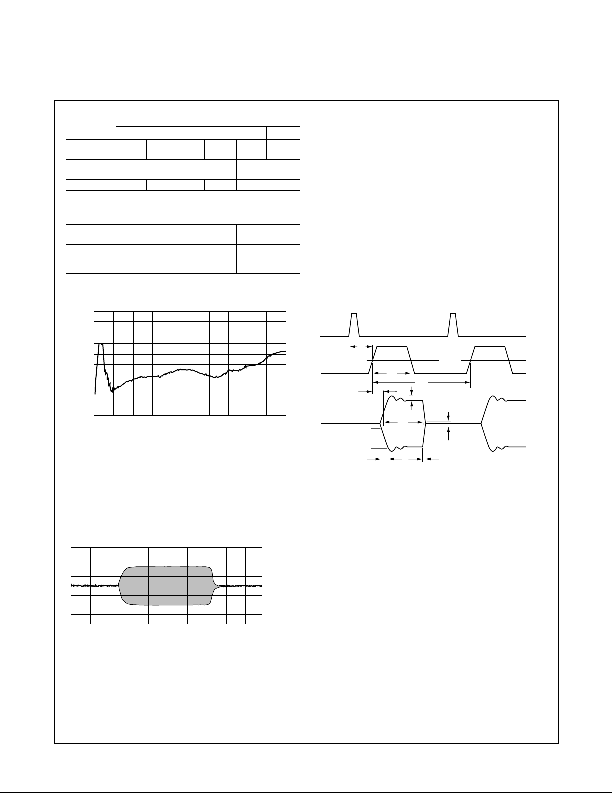
Pulse Modulation
1
MHz GHz
Carrier <25 25 to 64 to 128 to 500 to 1 to
Frequency <64 <128 <500 <1000 20
Minimum <1 µs <100 ns <25 ns
Pulse Width
Typically <10 ns
Rise/Fall Time <500 ns <350 ns <50 ns <35 ns <15 ns <10 ns
<20 mV
Video <2 mV peak-to-peak at 0 dBm peak-to-
Feedthrough peak
at 0 dBm
Pulse Width ±150 ns ±15 ns ±5 ns
Compression
Pulse Delay
(Video out <1 µsec <200 ns <125 ns <100 ns
to RF out)
3
On/off ratio: >80 dB
Carrier Frequency (GHz)
75
On/Off Ratio (dB)
85
95
105
115
125
0 4 8 12 16 20
Typical pulse modulation on/off ratio at +8 dBm.
Maximum pulse repetition frequency: >3 MHz
Minimum pulse duty cycle: no restrictions on duty cycle.
Pulse level accuracy: ±1.0 dB (relative to CW)
Pulse overshoot: <10 %
Input impedance: 50Ω nominal; TTL drive levels
Maximum leveled output power in pulse mode:
–0.5 dB (relative to CW)
Timebase = 10.0 ns/div
Carrier Frequency = 10.0 GHz
Risetime = 4.9 ns
Falltime = 2.05 ns
Typical pulse modulation envelope illustrates the fast
rise and fall times, excellent flatness and pulse fidelity
of the HP 83731B/83732B.
Internal Pulse Source
Pulse source modes: free-run, triggered with delay,
doublet and gated. Triggered with delay, doublet and
gated require external trigger source.
Pulse repetition frequency: 3 Hz to >3 MHz
Pulse repetition interval (PRI): 300 ns to 419 ms
Pulse width (T
W
): 25 ns to 419 ms
Variable pulse delay
Free-run mode (T
d
): ±419 ms
Triggered with delay and doublet modes (T
d
):
225 ns to 419 ms with ±25 ns jitter
Pulse width/delay/PRI resolution: 25 ns
Pulse delay (video to RF, T
m
):
1 to 20 GHz, <20 ns nominal
All pulse modulation specifications and supplemental
characteristics apply during use of internal pulse source.
Sync
Output
Video
Output
T
d
50% 50%
T
w
T
p
T
m
50%
RF Pulse
Output
10%
v
or
T
rf
v
f
90%
T
r
T
f
Tdvideo delay (variable) TmRF delay TrRF pulse rise time
Twvideo pulse width (variable) TrfRF pulse width Vorovershoot and ringing
Tppulse period (variable) TfRF pulse fall time Vfvideo feedthrough
HP 83731B, 83732B Modulation Specifications
Figure 1. (1 of 2) This figure shows modulation specifications that are available
only for the HP 83731B and 83732B, and not for the HP 83711B and 83712B.
1. CW power will be present for up to 10 ms when changing
frequency or power level.

Frequency Modulation
Rates: 1 kHz to 1 MHz
Flatness: ±2 dB
Frequency Maximum deviation
2
Modulation index
2 to 20 GHz 10 MHz peak
> 300
1 to <2 GHz 5 MHz peak
> 150
500 MHz to <1 GHz 2.5 MHz peak
> 75
256 to <500 MHz 1.25 MHz peak
> 37
The modulation index and maximum deviation decrease
by a factor of 2 for each octave below 256 MHz.
FM sensitivity:
Frequency Seven ranges, selectable:
1 to 20 GHz 10, 5, 3, 1, 0.3, 0.1, 0.03 MHz/V pk
256 MHz to
<
1 GHz 2500, 1250, 750, 250, 75, 25, 7.5 kHz/V pk
64 to <256 MHz 625, 312, 187, 62.5, 18.7, 6.25, 1.87 kHz/V pk
16 to <64 MHz 156, 78.1, 46.8, 15.6, 4.68, 1.56, 0.468 kHz/V pk
10 to <16 MHz 78.1, 39.0, 23.4, 7.81, 2.34, 0.871, 0.234 kHz/V pk
FM sensitivity accuracy: ±10% at 100 kHz
Incidental AM: <5%
FM input impedance: 600Ω nominal
Harmonic distortion: <1% (1 MHz peak deviation
at 100 kHz rate)
–5.00
5.00
Error (dB)
0
Log AM Error 10 GHz
Log AM Error 4-20 GHz
Log AM Error 1-4 GHz
Peak Power Level = 0 dBm
Desired Log AM Depth (attenuation) in dB
5 1015202530354045505560
Option 800 Phase Modulation
Sensitivity:
Two ranges, selectable:
Frequency Low Range High Range
1 to 20 GHz 1 rad/V pk 50 rad/V pk
256 MHz to
<
1 GHz 0.25 rad/V pk 12.5 rad/V pk
64 to <256 MHz .0625 rad/V pk 3.12 rad/V pk
16 to <64 MHz 0.0156 rad/V pk 0.781 rad/V pk
10 to <16 MHz 0.00781 rad/V pk 0.39 rad/V pk
Low Range High Range
Accuracy :
±5% (at 1 kHz) ±10% (at 100 Hz)
Flatness:
DC to 100 kHz: ±1 dB DC to 30 kHz: ±2 dB
Bandwidth:
>1 MHz (3 dB) usable to 1 MHz
at low deviations
Input Impedance:
600 ohms nominal 600 ohms nominal
Maximum Deviation:
2
Frequency Low Range High Range
2 to 20 GHz 4 rad 200 rad
1 to
<
2 GHz 2 rad 100 rad
500 to <1 GHz 1 rad 50 rad
256 to <500 MHz 0.5 rad 25 rad
The maximum deviation decreases by a factor of 2 for
each octave below 256 MHz.
Figure 1 . (2 of 2) This figure shows modulation specifications that are available
only for the HP 83731B and 83732B, and not for the HP 83711B and 83712B.
Linear Amplitude Modulation
Sensitivity: Two ranges, selectable:
30%/Vpk and 100%/Vpk
Sensitivity accuracy: (1 kHz)
±
8% of value ±2%,
(15 to 35 degC)
Maximum Depth: 90%
Bandwidth: (3 dB, 30% depth) DC to
>
100 kHz
Incidental phase modulation: (30% depth) <0.4
radians peak
Maximum carrier level in linear AM mode
(relative to CW):
With no modulation input:
<
1 GHz 1 to 4 GHz
>
4 GHz
0 dB
–
4.5 dB
–
1.0 dB
With modulation:
degrades up to 6 dB depending on depth
Typical log AM error (deviation from desired depth) at
25°C for carrier frequencies between 1.0 and 20 GHz.
Simultaneous Modulations
Full AM bandwidth and depth is available at any pulse
rate or width. FM/ΦM is completely independent of AM
and pulse modulation.
Logarithmic Amplitude
Modulation (Scan Modulation)
Maximum depth: > 60 dB
Sensitivity: –10 dB/V; (0 to +6V for 0 to –60 dBc)
Step response (50 dB change in level):
< 1 GHz, < 10 µs rise time, < 20 µs fall time
1 to 20 GHz, < 5 µs rise and fall times
Input impedance: 5000Ω nominal
Maximum leveled output power in log AM mode
(relative to CW):
<1 GHz 1 to 4 GHz >4 GHz
0 dB –4.5 dB –1.0 dB
4
2. With sine wave modulation only.
Option 1E2: Internal
Modulation Generator
Available in HP 83731B and HP 83732B models only.
Specifications for internal modulation are same as base
instrument, unless noted below.
Waveforms:
Sine wave: 0.5 Hz to 1 MHz rates
Ramp, square, triangle: 0.5 Hz to 100 kHz rates
Uniform noise, Gaussian noise
Rate accuracy: < ± .01%
Internal scan modulation:
Rate: 0.5 Hz to 20 kHz
Rate Resolution: 0.5 Hz (3 digits displayed)
Depth resolution: 0.01 dB
Internal linear AM:
Rate: 0.5 Hz to 100 kHz
Rate Resolution: 0.5 Hz (3 digits displayed)
Depth resolution: 0.1%
Internal FM:
Rate: 1 kHz to 1 MHz
Rate Resolution: 0.5 Hz (3 digits displayed)
Deviation resolution: 0.01 Hz
Flatness: ±2 dB (1 to 500 kHz)
Internal phase modulation (with Option 800 only):
Rate: 0.5 Hz to 1 MHz
Rate Resolution: 0.5 Hz (3 digits displayed)
Deviation resolution: 0.01 rad
Bandwidth: 700 kHz (3 dB) on low range
General
Noise Figure Meter Compatibility
HP 8370 sources are fully compatible with and can be
controlled by the HP 8970B noise figure meter through
Special Function 41.5.
Programming
These instruments are fully compatible with the Standard
Commands for Programmable Instruments (SCPI). SCPI
complies with IEEE 488.2-1987.
In addition, these instruments will emulate most applicable
HP 8673 commands, providing general compatibility with
ATE systems which include HP 8673 series signal
generators.
Environmental
Operating temperature range: 0° to 55°C
EMC: complies with CISPR Pub. 11/1990, Class A,and
Mil-Std-461C, Part 2, Methods CE03, CS01, CS02, RE02,
RS03
Power requirements
Power: 90 to 132V, 48 to 440 Hz; 198 to 264V, 48 to 66 Hz;
260 VA maximum.
Physical dimensions
Net weight: <16 kg (35 lb) Shipping: <23 kg (49 lb)
Size: 498 mm D x 426 mm W x 133 mm H (19.6in x 16.8in
x 5.2in)
Transit case available by ordering HP part number 9211-2655.
Front Panel Connectors
RF output
Type-N precision, or 3.5 mm precision (Option 1E9).
Nominal impedance is 50 ohms.
ALC in
Used for external leveling with either a power meter
or a positive or negative-polarity diode detector.
AM in (HP 83731B/83732B only)
Accepts input signal for external linear AM or
log AM. Nominal impedance is 5k ohms.
FM/ΦM in (HP 83731B/83732B only)
Accepts input signal for external FM or phase
modulation (Option 800 only). Nominal impedance
is 600 ohms.
Pulse/trigger gate in (HP 83731B/83732B only)
Accepts input signal for external pulse modulation.
Also accepts external trigger pulse input for internal
pulse modulation. TTL-level compatible, nominal
impedance is 50 ohms.
Pulse video out (HP 83731B/83732B only)
Outputs a signal that follows the RF output in all
pulse modes. TTL-level compatible, nominal source
impedance is 50 ohms.
Pulse sync out (HP 83731B/83732B only)
Outputs a synchronizing pulse, nominally 50 ns
width, during internal and triggered pulse
modulation. TTL-level compatible, nominal source
impedance is 50 ohms.
5
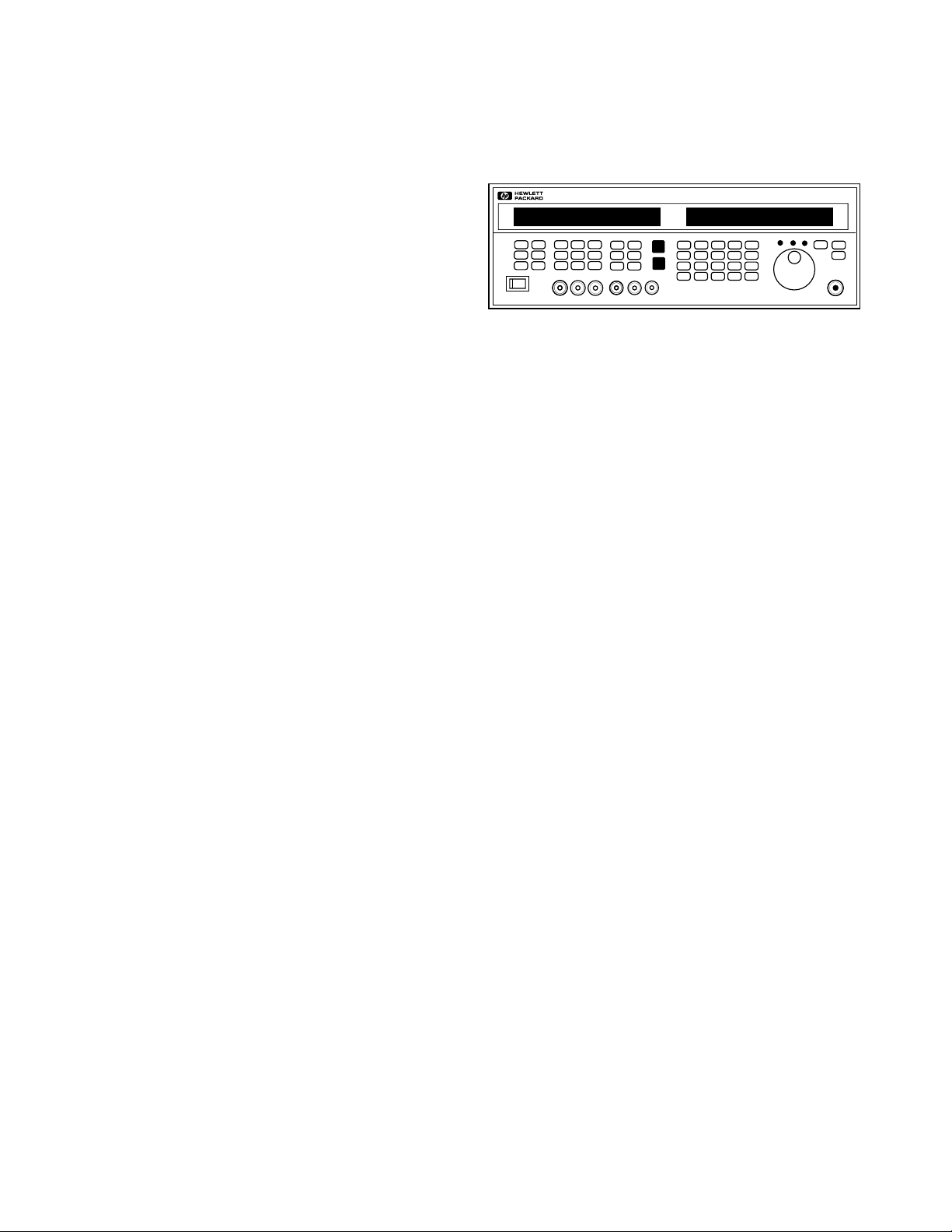
HP 83731B/83732B front panel

HP 83711B 1 to 20 GHz synthesized CW generator
HP 83712B 0.01 to 20 GHz synthesized CW generator
HP 83731B 1 to 20 GHz synthesized signal generator
HP 83732B 0.01 to 20 GHz synthesized signal generator
Option 1E1 Adds 110 dB output step attenuator
Option 1E2 Adds internal modulation generator (HP 83731B/32B only)
Option 1E5 Adds high-stability timebase
Option 1E8 1 Hz frequency resolution
Option 1E9 3.5 mm RF output connector
Option 800 Analog phase modulation (HP 83731B/32B only)
Option 0B2 Extra operating manual
Option 0BV Service documentation, component level
Option 0BW Service documentation, assembly level
Option 1CM Rack mount kit (HP part number 5062-3977)
Option 1CP Rack mount and handle kit (HP part number 5062-3983)
Option 1CR Rack slide kit (HP part number 1494-0059)
Option W30 Two additional years return to-HP-service
Option W32 Three-year return-to-HP calibration service
Option W34 Three-year Mil-Std calibration service
Longer term warranty and calibration services are available.
Ordering Information
HP 83731B/83732B rear panel
10 MHz input
Accepts a 10 MHz ±100 Hz, 0 to 10 dBm, external
reference signal for operation from an external high
stability timebase. Nominal input impedance is 50Ω.
10 MHz output
Outputs the 10 MHz reference signal, nominally +3 dBm,
for use as an external reference signal. Nominal source
impedance is 50Ω.
0.5V/GHz output
Supplies a voltage proportional to output frequency for
use with mm-wave frequency multipliers, including the
HP 83550 Series Millimeter Wave Source Modules.
AM output (Option 1E2 only)
Provides a sample of the modulating signal from the
internal AM generator or external AM input.
FM/ΦM output (Option 1E2 only)
Provides a sample of the modulating signal from the
internal FM/ΦFM generator or external FM/ΦFM input.
Data Subject to Change
Copyright © 1995
Hewlett-Packard Company
Printed in U.S.A. 3/95
5963-6615E
8370 SERIES
GENERATOR
For more information, call your
local HP sales office listed in your
telephone directory .
Rear Panel Connectors
 Loading...