


10 MHz to 110 GHz
Specifications apply after full user calibration,
and in coupled attenuator mode of operation
(ALC level greater than –10 dBm).
Frequency
Range:
83620B 10 MHz to 20 GHz
83622B 2 GHz to 20 GHz
83623B 10 MHz to 20 GHz (high power)
83624B 2 GHz to 20 GHz (high power)
83630B 10 MHz to 26.5 GHz
83640B 10 MHz to 40 GHz
83650B 10 MHz to 50 GHz
83623L 10 MHz to 20 GHz
83630L 10 MHz to 26.5 GHz
83640L 10 MHz to 40 GHz
83650L 10 MHz to 50 GHz
Resolution:
Standard 1 kHz
Option 008 1 Hz
Frequency bands (for CW signals):
Frequency range n
10 MHz to <2 GHz 1
2 GHz to <7 GHz 1
7 GHz to <13.5 GHz 2
13.5 GHz to <20 GHz 3
20 GHz to <26.5 GHz 4
26.5 GHz to <38 GHz
1
6
38 GHz to 50 GHz 8
Internal 10 MHz time base
Accuracy = Calibration ± Aging Rate ± Temperature
Effects ± Line Voltage Effects
Aging Rate: 5 ´ 10
–10
/day, 1 ´ 10–7/year
With Temperature: 1 ´ 10
–10
/°C, typical
With Line Voltage: 5 ´ 10
–10
for line voltage change
of 10%, typical
Sweep functions
Control: Start/stop, center/span, marker (M1-M2),
alternate sweep
Trigger: auto, external, single, or GPIB
Sweep modes
CW and manual modes
Accuracy: Same as time base
Switching Time:
For steps within a frequency band:
15 ms + (step size/1 GHz) ´ 5 ms step size
Maximum, or across band switch points: 50 ms
Step or list modes within a frequency band:
5 ms
2
+ (step size /1 GHz) ´ 5 ms
Agilent
8360B Series Synthesized Swept
Signal Generators
8360L Series Synthesized Swept
CW Generators
Data Sheet
1. This band is 26.5 GHz to 40 GHz for the 83640B/L.
Step sweep mode
Accuracy: Same as time base
Minimum Step Size: Same as frequency resolution
Number of Points: 2 to 801
Switching Time: Same as CW
Dwell Time: 100 µs to 3.2 s
List mode
Accuracy: Same as time base
Minimum step size: Same as frequency resolution
Number of points: 1 to 801
Switching time: Same as CW
Dwell time: 100 µs to 3.2 s
Ramp sweep mode
Accuracy (sweep time ³100 ms and ²5 s):
Sweep widths >n ´ 10 MHz: (start, stop, and
bandedge frequencies are phase-locked
corrected during sweep)
Lesser of 1% of sweep width or n ´ 1 MHz
+ 0.1% of sweep width.
Sweep time: 10 ms to 100 s, 300 MHz/ms
maximum rate
RF output
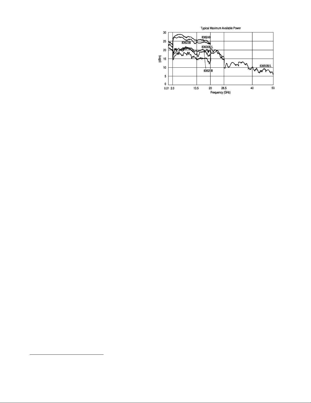
Output power
Maximum leveled (dBm)
2
Standard Option 006
(B models only)
83620B, 83622B +13 +13
83623B +17 +17
83623L +15 Not applicable
83624B +20 +17
83630B/L
Output frequencies <20 GHz +13 +13
Output frequencies ³20 GHz +10 +10
83640B/L
Output frequencies <26.5 GHz +10 +10
Output frequencies ³26.5 GHz +6 +6
83650B/L
Output frequencies <26.5 GHz +10 +10
Output frequencies ³26.5 GHz +5 +5
and <40 GHz
Output frequencies ³40 GHz +2.5 +2.5
With attenuator (Option 001): Minimum settable
output power is –110 dBm. Maximum leveled
output power is reduced by 1.5 dB to 20 GHz,
2 dB above 20 GHz, and 2.5 dB above 40 GHz.
Minimum settable
Standard: –20 dBm
Option 001: –110 dBm
Resolution: 0.02 dB
Switching time (without attenuator change):
10 ms, typical
Temperature stability: 0.01 dB/°C, typical
Accuracy (dB)
3,4
Specifications apply in CW, step, list, manual
sweep, and ramp sweep modes of operation.
Frequency (GHz)
Power <2.0 ³2.0 >20
and ²20 and ²40 >40
>+10 dBm ±1.2 ±1.3
>–10 dBm
5
±0.6 ±0.7 ±0.9 ±1.7
>–60 dBm ±0.9 ±1.0 ±1.2 ±2.0
²–60 dBm ±1.4 ±1.5 ±1.7 ±2.5
User flatness correction
Number of points: 2 to 801 points/table.
Number of tables = up to 8
Entry modes: GPIB power meter, GPIB bus,
and manual.
Flatness (dB)
Specifications apply in CW, step, list, manual
sweep, and ramp sweep modes of operation.
Frequency (GHz)
Power <2.0 ³2.0 >20
and ²20 and ²40 >40
>+10 dBm ±0.9 ±1.0
>–10 dBm
7
±0.5 ±0.6 ±0.8 ±1.5
>–60 dBm ±0.7 ±0.8 ±1.0 ±1.7
²–60 dBm ±1.1 ±1.2 ±1.4 ±2.1
2. Specification applies over the 0 °C to 35 °C temperature range (0 °C to 25 °C for output frequencies >20 GHz). Maximum leveled output power over
the 35 °C to 55 °C temperature range typically degrades by less than 2 dB.
3. Includes flatness.
4. Specifications apply over the 15 °C to 35 °C temperature range for output frequencies <50 MHz
5. Specifications apply over the 15 °C to 35 °C temperature range and are degraded 0.3 dB outside of that range.

3
Analog power sweep
Range: –20 dBm to maximum available power, can
be offset using step attenuator.
External leveling
Range:
At external 33330D/E detector: –36 to +4 dBm
At external leveling input: –200 µV to –0.5 volts
Bandwidth
External detector mode: 10 or 100 kHz (sweep
speed and modulation mode dependent),
nominal
Power meter mode: 0.7 Hz, nominal
Source match
(internally leveled), typical
6
<20 GHz 1.6:1 SWR
<40 GHz 1.8:1 SWR
<50 GHz 2.0:1 SWR
Spectral purity
Specifications apply in CW, step, list, and manual
sweep modes of operation. Specifications for
harmonics beyond maximum instrument frequencies are typical.
Spurious signals (dBc)
Harmonics
Agilent model numbers
Output 83620B 83623B 83623L 83630B/L 83640B/L
frequencies 83622B 83624B 83650B/L
<2.0 GHz
Standard –30 –25
7
–257–30 –30
7
Option 006 –30
7
–25
7
–30
7
–30
7
³2.0 GHz and
<26.5 GHz
Standard –50 –25 –45 –50 –50
Option 006 –60 –60 –60 –50
³26.5 GHz
Standard –40
Option 006 –40
Subharmonics
Output 83620B 83623B 83623L 83630B/L 83640B/L
frequencies 83622B 83624B 83650B/L
<7 GHz None None None None None
³7 and
²20 GHz –50 –50 –50 –50 –50
>20 GHz and
²40 GHz –50 –40
8
>40 GHz –35
8
6. Typically 2.0:1 SWR at frequencies below 50 MHz.
7. Specification is –20 dBc below 50 MHz.
8. Specifications typical below 0 dBm.

Nonharmonically related
10 MHz to <2.0 GHz9–60
³2.0 to <20 GHz –60
>20 GHz to ²26.5 GHz –58
>26.5 to ²40 GHz –54
³40 GHz to ²50 GHz –52
Power-line related (<300 Hz offset from carrier)
10 MHz to <7 GHz –55
7 GHz to <13.5 GHz –49
13.5 GHz to 20 GHz –45
>20 GHz to <26.5 GHz –43
26.5 GHz to <38 GHz
10
–39
38 GHz to 50 GHz –37
Single-sideband phase noise (dBc/Hz)
Offset from carrier
Frequency range 100 Hz 1 kHz 10 kHz 100 kHz
10 MHz to <7 GHz –70 –78 –86 –107
7 GHz to <13.5 GHz –64 –72 –80 –101
13.5 GHz to 20 GHz –60 –68 –76 –97
>20 GHz to <26.5 GHz –58 –66 –74 –95
26.5 GHz to <38 GHz10–54 –62 –70 –91
38 GHz to 50 GHz –52 –60 –68 –89
Residual FM (rms, 50 Hz to 15 kHz bandwidth)
CW mode or Sweep widths ²n ´ 10 MHz: n ´ 60 Hz,
typical
Sweep widths >n ´ 10 MHz: n ´ 15 kHz, typical
Modulation
All modulation specifications are only applicable
to the Agilent 8360B series. Pulse modulation
specifications apply for output frequencies
400 MHz and above.
Pulse (8360B only)
Standard Option 006
On/off ratio
11
80 dB 80 dB
Rise/fall times 25 ns 10 ns
Minimum width
12
Internally leveled 1 µs 1 µs
Search mode
Output frequencies <2.0 GHz 50 ns 50 ns
Output frequencies ³2.0 GHz 50 ns 15 ns
ALC off mode
Output frequencies <2.0 GHz 50 ns 50 ns
Output frequencies ³2.0 GHz 50 ns 15 ns
Minimum repetition frequency
Internally leveled 10 Hz 10 Hz
Search mode DC DC
ALC off mode DC DC
Level accuracy
(dB, relative to CW level)
Widths ³1 µs ±0.3 ±0.3
Widths <1 µs (Search Mode) ±0.5, typical ±0.5, typical
Video feedthrough
Output frequencies <2.0 GHz
Power levels ²10 dBm 2% 2%
Power levels >10 dBm 5% 5%
Output frequencies ³2.0 GHz
83620B, 83622B, 83630B 0.1% 1%
83623B, 83624B, 83640B, 83650B 1% 1%
Overshoot, ringing 15%, typical 10%, typical
Delay
13
Output frequencies <2.0 GHz 80 ns, typical 80 ns, typical
Output frequencies ³2.0 GHz 80 ns, typical 40 ns, typical
Compression ±10 ns, typical ±5 ns, typical
Internal pulse generator
Width range: 1 µs to 65 ms
Period range: 2 µs to 65 ms
Resolution: 1 µs
9. Specification applies at output levels 0 dBm and below.
10. Frequency range is 26.5 GHz to 40 GHz on the 83640B/L.
11. In the 83623B/83624B, specification applies at ALC levels 0 dBm and above, and over the 20 °C to 55 °C temperature range. Specification
degrades 5 dB below 20 °C, and 1 dB per dB below ALC level 0 dBm in those models.
12. With external input. Internal pulses are limited by minimum width of internal pulse generator.
13. Option 002 adds 30 ns delay and ±5 ns pulse compression for external pulse inputs. AM and Scan Bandwidth (3 dB, 30% depth,
modulation peaks 3 dB below maximum rated power): DC to 250 kHz.
4

5
AM and scan (8360B only)
Bandwidth (3 dB, 30% depth, modulation peaks
3 dB below maximum rated power): DC to 100 kHz
Modulation depth
(ALC levels noted, can be offset using step attenuator)
Normal Mode: –20 dBm to maximum available power
Deep Mode14: 50 dB below maximum available
power
Unleveled Mode15: 50 dB below maximum available
power
Sensitivity
Linear: 100%/volt
Accuracy (1 kHz rate, 30% depth, normal mode):
5%
Exponential: 10 dB/volt
Accuracy (normal mode): 0.25 dB ±5% of depth
in dB
Incidental phase modulation (30% depth): 0.2
radians peak, typical
Incidental FM: Incidental phase modulation ´
modulation rate
FM (8360B only)
Locked mode
Maximum deviation: ±8 MHz
Rates (3 dB bandwidth, 500 kHz deviation):
100 kHz to 8 MHz
Maximum modulation index (deviation/rate): n ´ 5
Unlocked mode
Maximum deviation
At rates ²100 Hz: ±75 MHz
At rates >100 Hz: ±8 MHz
Rates (3 dB bandwidth, 500 kHz deviation): DC to
8 MHz
Sensitivity
100 kHz, 1 MHz, or 10 MHz/volt, switchable.
Accuracy (1 MHz rate, 1 MHz deviation): 10%
Simultaneous modulations (8360B only)
Full AM bandwidth and depth is typically available
at any pulse rate or width. FM is completely independent of AM and pulse modulation.
Internal modulation generator (Option 002)
AM, FM modulation signals
Internal waveforms: Sine, square, triangle,
ramp, noise
Rate
Range:
Sine: 1 Hz to 1 MHz
Square, triangle, ramp: 1 Hz to 100 kHz
Resolution: 1 Hz
Depth, deviation
Range: same as the base instrument
Resolution: 0.1%
Accuracy: same as base instrument
Pulse
Modes: free-run, gated, triggered, delayed
Period range: 300 ns to 400 ms
Width range: 25 ns to 400 ms
Resolution: 25 ns
Accuracy: 5 ns
Video delay
Internal sync pulse: 0 to 400 ms
Externally supplied sync pulse: 225 ns to 400 ms
Modulation meter
Accuracy (rates ²100 kHz): 5% of range)
14. Deep mode offers reduced distortion for very deep AM. Waveform is DC-coupled and feedback-leveled at ALC levels above –13 dBm. At ALC levels below
–13 dBm, output is DC-controllable, but subject to sample-and-hold drift of 0.25 dB/second.
15. The 8360 has two unleveled modes, ALC Off and Search. In ALC Off mode, the modulator drive can be
controlled from the front panel to vary quiescent RF output level. In Search mode, the instrument microprocessor
momentarily closes the ALC loop to find the modulator drive setting necessary to make the quiescent RF output level equal to an entered value, then opens
the ALC loop while maintaining that modulator drive setting. Neither of these modes is feedback leveled.

6
General
Storage temperature range: –40 °C to 75 °C
Operating temperature range: 0 °C to 55 °C
Environmental
EMC: Within limits of CISPR Pub.11/1990 Group 1,
Class A, and Mil-Std-461C Part 7 RE02
Warm-up time
Operation: Requires 30-minute warm-up from cold
start at 0 °C to 55 °C. Internal temperature equilibrium reached after two-hour warm-up at stable
ambient temperature.
Frequency reference: Reference time base is kept at
operating temperature with the instrument connected to AC power. Instruments disconnected
from AC power for more than 24 hours require
30 days to achieve time base aging specification.
Instruments disconnected from AC power for less
than 24 hours require 24 hours to achieve time
base aging specification.
Power requirements
48 to 66 Hz; 115 volts (+10/–25%) or 230 volts
(+10/–15%); 400 VA maximum (30 VA in STANDBY)
Weight and dimensions
Net weight: 27 kg (60 lb)
Shipping weight: 36 kg (80 lb)
Dimensions: 178 H ´ 425 W ´ 648 mm D
(7.0 ´ 16.75 ´ 22.5 inches)
Adapters supplied
83620B, 83622B, 83623B/L, 83624B, 83630B/L
Type N (female) – 3.5 mm (female) Part Number 1250-1745
3.5 mm (female) – 3.5 mm (female) Part Number 5061-5311
83640B/L, 83650B/L
2.4 mm (female) – 2.92 mm (female) Part Number 1250-2187
2.4 mm (female) – 2.4 mm (female) Part Number 1250-2188
Inputs and outputs
Auxiliary output
Provides an unmodulated reference signal from
2 to 26.5 GHz at a typical minimum power level of
–10 dBm. Nominal output impedance 50 ohms.
(SMA female, rear panel.)
RF output
Nominal output impedance 50 ohms. (Precision
3.5 mm male on 20 and 26.5 GHz models, 2.4 mm
male on 40 and 50 GHz models, front panel.)
External ALC input
Used for negative external detector or power meter
leveling. Nominal input impedance 120 kohms,
damage level ±15 volts. See RF Output specifications. (BNC female, front panel.)
Pulse input/output (8360B models only)
TTL-low-level signal turns RF off. When using
standard internal pulse generator a TTL -level
pulse sync signal preceeding the RF pulse by nominally 80 ns is output at this connector. Nominal
input impedance 50 ohms, damage level +5.5,
–0.5 volts. See Modulation specifications. (BNC
female, front panel.)
AM input (8360B models only)
Nominal input impedance 50 ohms (internally
switchable to 2 kohms), damage level ±15 volts.
See Modulation specifications. (BNC female, front
panel.)
FM input (8360B models only)
Nominal input impedance 50 ohms (internally
switchable to 600 ohms), damage level ±15 volts.
See Modulation specifications. (BNC female, front
panel.)
Trigger input
Activated on TTL rising edge. Used to externally
activate an analog sweep or to advance to the next
point in step or list mode. Damage level +5.5,
–0.5 volts. (BNC female, rear panel.)
Trigger output
Outputs a one-microsecond-wide TTL pulse at 1601
points evenly spaced across an analog sweep, or at
each point in step or list mode. (BNC female, rear
panel.)
10 MHz reference input
Accepts 10 MHz ±100 Hz, 0 to +10 dBm reference
signal for operation from external time base.
Nominal input impedance 50 ohms. Damage level
+10, –5 volts. (BNC female, rear panel.)
10 MHz reference output
Nominal signal level 0 dBm, nominal output impedance 50 ohms. (BNC female, rear panel.)
Sweep output
Supplies a voltage proportional to the sweep ranging from 0 volts at start of sweep to 10 volts at end
of sweep, regardless of sweep width. In CW mode,
voltage is proportional to percentage of full instrument frequency range. Minimum load impedance
3 kohms. Accuracy ±0.25%, ±10 mv, typical. (BNC
female, rear panel.)
Stop sweep input/output
Sweep will stop when grounded externally. TTLhigh while sweeping, TTL-low when 8360 stops
sweeping. Damage level +5.5, –0.5 volts. (BNC
female, rear panel.)

7
Z-Axis blanking/markers output
Supplies positive rectangular pulse (approximately
+5 volts into 2 kohms) during the retrace and band
switchpoints of the RF output. Also supplies a negative pulse (–5 volts) when the RF is at a marker
frequency (intensity markers only). (BNC female,
rear panel.)
Volts/GHz output
Supplies a voltage proportional to output frequency
at 0.25 volts/GHz, 0.5 volts/GHz, or 1 volt/GHz
(model dependant and internally switchable).
Maximum output 18 volts. Minimum load impedance 2 kohms. Accuracy ±0.5%, ±10 mv, typical.
(BNC female, rear panel.)
Source module interface
Provides bias, flatness correction, and leveling connections for the 83550 series of millimeter-wave
source modules. (Special, front, and rear panels.)
Auxiliary interface
Provides control signal connections to the 8516A
S-parameter test set. Also used when two 8360
series synthesized sweepers are operated in master/slave mode. (25-pin D-subminiature receptacle,
rear panel.)
Pulse video output (Option 002 only.) Outputs the
pulse modulation waveform that is supplied to the
modulator. This can be either the internally or
externally generated pulse modulation signal.
(BNC female, rear panel.)
Pulse sync out (Option 002 only.) Outputs a 50 ns
wide TTL pulse synchronized to the leading edge of
the internally generated pulse. (BNC female, rear
panel.)
AM/FM output (Option 002 only.) Outputs the internally generated AM or FM waveform. This output
can drive 50 ohms or greater. The AM output is
scaled the same as it is generated, either 100%/V or
10 dB/V. The FM scaling depends on the FM deviation selected. (BNC female, rear panel.)
Models
83620B 10 MHz to 20 GHz
83622B 2 GHz to 20 GHz
83623B 10 MHz to 20 GHz (high power)
83624B 2 GHz to 20 GHz (high power)
83630B 10 MHz to 26.5 GHz
83640B 10 MHz to 40 GHz
83650B 10 MHz to 50 GHz
83623L 10 MHz to 20 GHz
83630L 10 MHz to 26.5 GHz
83640L 10 MHz to 40 GHz
83650L 10 MHz to 50 GHz
Options
Option 001 adds step attenuator
With this option, minimum settable output power
is –110 dBm. Maximum leveled output power is
reduced by 1.5 dB to 20 GHz, 2 dB above 20 GHz,
and 2.5 dB above 40 GHz.
Option 002 adds internal modulation generator
(8360B only – not available on 8360L)
Adds a digitally synthesized modulation waveform
source-on-a-card to the 8360. Provides signals that
would otherwise be applied to the external modulation inputs.
Option 004 rear panel RF output
Moves RF output, external ALC input, pulse
input/output, AM input, and FM input connectors
to the rear panel.
Option 006 fast pulse modulation
(8360B only – not available on 8360L)
Improves pulse rise/fall time to 10 ns. Also
improves harmonic performance.
Option 008 1 Hz frequency resolution
Provides frequency resolution of 1 Hz.
Option 700 MATE system compatibility
Provides CIIL programming commands for MATE
system compatibility.
Option 806 rack slide kit
Used to rack mount the 8360 while permitting
access to internal spaces.
Option 908 rack flange kit
Used to rack mount the 8360 without front handles.
Option 910 extra operating and service manuals
Provides a second copy of Operating and Service
manuals.
Option 913 rack flange kit
Used to rack mount the 8360 with front handles.
Front handles are standard on the 8360.
ISO 9002 compliant
These models are manufactured in an ISO 9002
registered facility in concurrence with Agilent
Technologies’ commitment to quality.
Upgrades
Model and frequency upgrades are available.
Please contact your Agilent sales representative
for details.

8
Dedicated Agilent 8510 system source models
Dedicated source are optimized for use as 8510
network analyzer system components. They are
configured without modulation capabilities or front
panel keyboard/displays, and with rear connectors
and with one-year on-site service (where available).
Specifications for these models are the 8510 specifications, plus the following:
Frequency range
83621B 45 MHz to 20 GHz
83631B 45 MHz to 26.5 GHz
83651B 45 MHz to 50 GHz
Resolution: 1 Hz
Accuracy
CW Mode: Same as time base
16
Swept Mode (at frequencies ²26.5 GHz):
Sweep Widths ²n ´ 10 MHz: 0.1% of sweep width ±
time base accuracy
Sweep Widths >n ´ 10 MHz and ²400 MHz:
1% of sweep width
Sweep Widths >400 MHz and ²4 GHz: 4 MHz
Sweep Widths >4 GHz: 0.1% of sweep width
Swept Mode (at frequencies >26.5 GHz):
Sweep Widths ²n ´ 10 MHz: 0.1% of sweep width
± time base accuracy
Sweep Widths >n ´ 10 MHz and ²800 MHz: 1% of
sweep width
Sweep Widths >800 MHz and ²8 GHz: 8 MHz
Sweep Widths >8 GHz: 0.1% of sweep width
Output power
Maximum leveled
Frequencies ²20 GHz: +10 dBm
Frequencies >20 GHz and ²26.5 GHz: +4 dBm
Frequencies >26.5 GHz and ²40 GHz: +3 dBm
Frequencies >40 GHz: 0 dBm
Minimum settable: –20 dBm
Specifications describe warranted instrument performance over the 0 °C to 55 °C
temperature range, except as noted otherwise. Supplemental characteristics,
denoted as typical or nominal, are intended to provide information useful in applying
the instrument, but are non-warranted parameters.
16. Internal time base verified to 1 ppm with standard on-site verification
procedure.
Agilent Technologies Test and Measurement
Support, Services, and Assistance
Agilent Technologies aims to maximize the value
you receive, while minimizing your risk and problems. We strive to ensure that you get the test
and measurement capabilities you paid for and
obtain the support you need. Our extensive support resources and services can help you choose
the right Agilent products for your applications
and apply them successfully. Every instrument
and system we sell has a global warranty.
Support is available for at least five years beyond
the production life of the product. Two concepts
underlie Agilent's overall support policy: "Our
Promise" and "Your Advantage."
Our Promise
Our Promise means your Agilent test and
measurement equipment will meet its advertised
performance and functionality. When you are
choosing new equipment, we will help you with
product information, including realistic performance specifications and practical recommendations from experienced test engineers. When
you use Agilent equipment, we can verify that it
works properly, help with product operation, and
provide basic measurement assistance for the
use of specified capabilities, at no extra cost
upon request. Many self-help tools are available.
Your Advantage
Your Advantage means that Agilent offers a wide
range of additional expert test and measurement
services, which you can purchase according to
your unique technical and business needs. Solve
problems efficiently and gain a competitive edge
by contracting with us for calibration, extra-cost
upgrades, out-of-warranty repairs, and on-site
education and training, as well as design, system integration, project management, and other
professional engineering services. Experienced
Agilent engineers and technicians worldwide
can help you maximize your productivity, optimize the return on investment of your Agilent
instruments and systems, and obtain dependable
measurement accuracy for the life of those
products.
For more assistance with your test and
measurement needs or to find your local
Agilent office go to:
www.agilent.com/find/assist
Or contact the test and measurement experts at
Agilent Technologies:
1 800 452 4844 (8am-8pm EST)
Product specifications and descriptions in this
document subject to change without notice.
Copyright ©2000 Agilent Technologies
Printed in USA 07/00
5964-6162E
 Loading...