


The Agilent Technologies 83599A
(10 MHz to 50 GHz) and 83598A
(2.4 GHz to 50 GHz) RF plug-ins for
the Agilent 8350B sweep oscillator
mainframe combine excellent performance and reliability in two broadband coaxial swept frequency sources.
These plug-ins feature high output
power (+10 dBm to 20 GHz, +3 dBm
to 40, and 0 dBm to 50 GHz), as well
as excellent harmonic performance
(<–45 dBc from 1.5 to 20 GHz, <–40 dBc
to 40 GHz, and <–35 dBc to 50 GHz).
For applications requiring additional
power to 20 GHz, these plug-ins also
provide a switch selectable high power
mode which boosts the RF output to
+15 dBm from 2.4 to 20 GHz.
50 GHz coaxial coverage
The 83599A and 83598A plug-ins
incorporate 2.4 mm connectors which
make high performance broadband
coaxial measurements possible. The
superiority of 2.4 mm connectors lies
in their ruggedness, repeatable performance, and excellent match over
the entire frequency range. 2.4 mm
connectors are also incorpoated into
other Agilent instrumentation and
devices so that a complete 10 MHz
to 50 GHz coaxial system can be
configured.
Agilent 83599A and 83598A
RF Plug-ins for the Agilent
8350B Sweep Ocillator
Data Sheet
10 MHz to 50 GHz
Typical output power available from the
Agilent 83599A in normal (versus high
power) operating mode
2
Unsurpassed versatility
With these additions, the 8350B
sweeper family offers a choice of
twenty Agilent 83500 series plug-ins.
The 8350B has a straightforward
front panel with easy-to-use knob,
step, and data entry keyboard controls. Almost all plug-in functions are
fully programmable via the Agilent
Interface Bus. Numerous features
such as power sweep, slope, alternate
sweep, save/recall registers, and five
independent markers emphasize the
8350B’s versatility.
Outstanding reliability
The 8350B mainframe and all 83500
series plug-ins are backed with a oneyear warranty on the instrument and
a two-year warranty on microcircuits.
These microcircuits are also established on our microcircuit exchange
program to further minimize the cost
of ownership. Option W30 on the
mainframe and plug-ins guarantees a
low cost of ownership by providing
two additional years of service at a
low price.
Applications
Scalar network analysis
Testing components up to 50 GHz in a
coaxial environment is now possible
with the 83599A and 83598A RF plugins. A broadband swept scalar measurement system is easy to configure
using these 50 GHz sweepers with the
Agilent 8757C/E scalar network analyzer and the appropriate 2.4 mm
scalar accessories.
Simultaneously measure a device’s
reflection and transmission characteristics by using the 85027D 10 MHz
to 50 GHz 2.4 mm directional bridge
to measure the reflected signal and
the 85025D 10 MHz to 50 GHz 2.4 mm
detector to measure the transmitted
signal. Improve measurement accuracy
by ratioing. Ratioing can be accomplished by adding an Agilent 11667C
10 MHz to 50 GHz 2.4 mm power
splitter and a second 85025D detector
to measure the reference signal.
The 8757C/E scalar network analyzer
can operate in either AC-detection
mode for reliable drift-free measurements or in DC-detection mode for
accurate swept power measurements.
Scalar measurement dynamic range is
maximized by the plug-ins’ excellent
harmonic performance, making them
an ideal choice for scalar network
analysis.
Local oscillator
The broadband frequency coverage
and high output power of the 83599A
and 83598A RF plug-ins make them
ideal as local oscillators for downconverting high frequency signals to a
lower intermediate frequency. These
plug-ins provide the broadest frequency
coverage for mixer measurements systems where a 50 GHz coaxial local
oscillator is required. Coaxial noise
figure measurements up to 50 GHz
are also possible using the Agilent
8970B noise figure meter with an
83599A or 83598A plug-in. In this
application, the plug-in is used to
downconvert the high frequency signals to the 10 to 1600 MHz range of
the noise figure meter.
Stand alone source
The outstanding performance of the
83599A and 83598A RF plug-ins make
them especially attractive as stand
alone sources for various signal generation and simulation applications.
In addition to their broad frequency
coverage, these plug-ins provide
greater than 45 dBc of harmonic and
subharmonic suppression from 1.5 to
20 GHz, greater than 40 dB to 40 GHz,
and greater than 35 dB to 50 GHz. They
also provide CW frequency accuracies
of better than ±5 to ±25 MHz depending on the frequency of operation.
These plug-ins have very flexible amplitude, frequency, and pulse modulation
capabilities. For example, ±75 MHz
deviations are possible for frequency
modulation rates of DC to 100 Hz. An
internal pulse modulator provides
calibrated leveled pulses with as narrow as 1.5 µ sec widths and 50 nsec
rise/fall times. Finally, both plug-ins
provide an optional 60 dB step attenuator which allows output power control from +10 to –72 dBm.
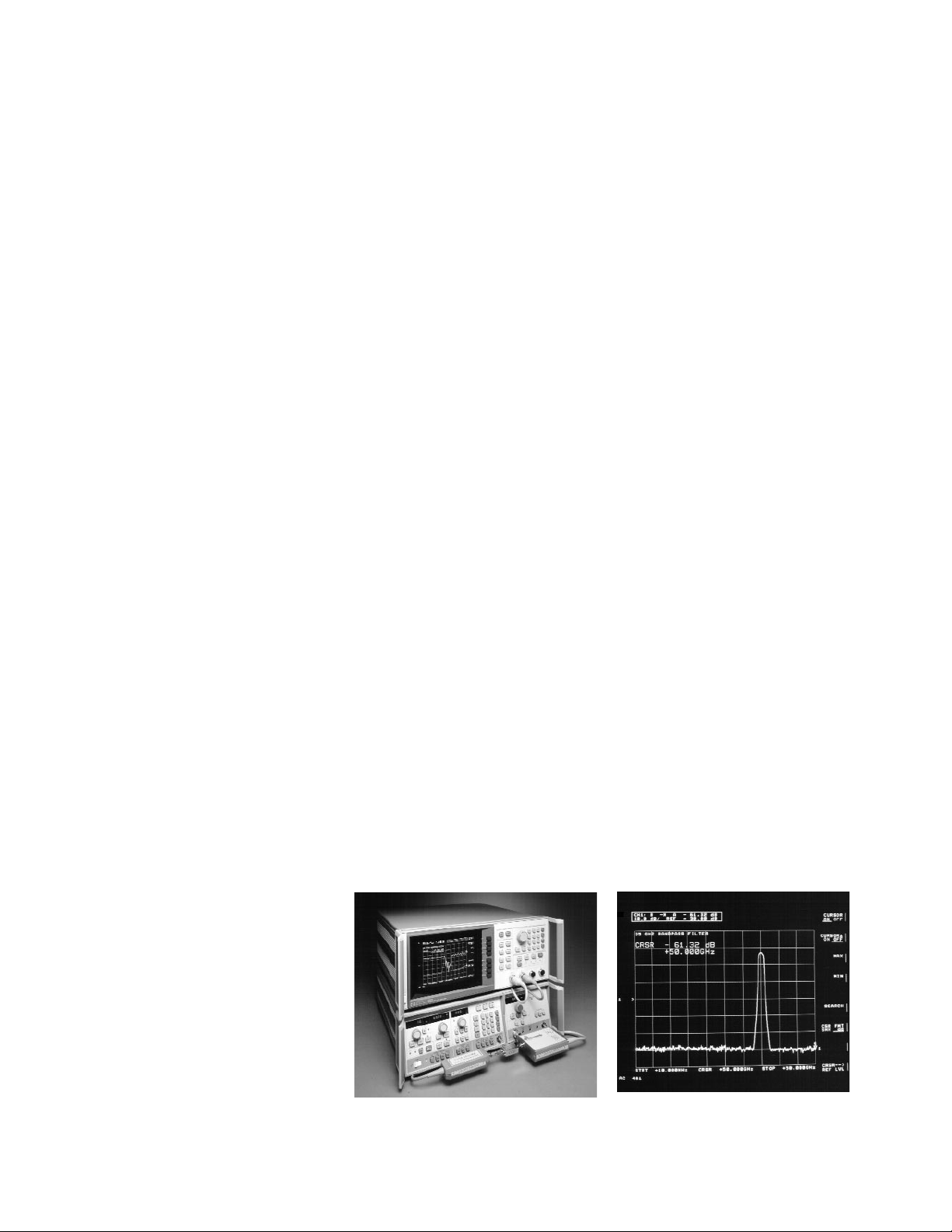
Transmission response of a 35 GHz bandpass filter
10 MHz to 50 GHz scalar network analyzer
system

3
Specifications
Specifications describe the instrument’s warranted performance over the temperature range of 0° to 55°C (except where
noted). Supplemental characteristics are intended to provide information useful in applying the instrument by giving typi-
cal but non-warranted performance parameters. These are denoted as “typical,” “nominal,” or “approximate.”
Band 0 Band 1 Band 2 Band 3 Band 4 Full Band
Frequency Characteristics
Range
83599A 0.01 to 2.4 GHz 2.4 to 7.0 GHz 7.0 to 14.0 GHz 14.0 to 26.5 GHz 26.5 to 50.0 GHz 0.01 to 50.0 GHz
83598A 2.4 to 7.0 GHz 7.0 to 14.0 GHz 14.0 to 26.5 GHz 26.5 to 50.0 GHz 2.4 to 50.0 GHz
Accuracy
1
CW Mode ±5 MHz ±5 MHz ±10 MHz ±20 MHz ±25 MHz
All Sweep Modes
2
±15 MHz ±20 MHz ±25 MHz ±50 MHz ±65 MHz ±100 MHz
Frequency Markers
3
±15 MHz, ±0.5% ±20 MHz, ±0.5% ±25 MHz, ±0.5% ±50 MHz, ±0.5% ±65 MHz, ±0.5% ±100 MHz, ±0.5%
of sweep width of sweep width of sweep width of sweep width of sweep width of sweep width
Linearity:3typically ±2 MHz ±2 MHz ±4 MHz ±10 MHz ±12 MHz ±20 MHz
Stability
With Temperature: typical ±200 kHz/°C ±200 kHz/°C ±400 kHz/°C ±800 kHz/°C ±1.6 MHz/°C
With 10 dB Power Change ±100 kHz ±100 kHz ±100 kHz ±200 kHz ±250 kHz
With 3:1 Load SWR ±100 kHz ±100 kHz ±100 kHz ±100 kHz ±200 kHz
With Time:4Typical ±100 kHz ±100 kHz ±200 kHz ±400 kHz ±800 kHz
Residual FM (peak):
5
<5 kHz <5 kHz <7 kHz <14 kHz <24 kHz
Output Characteristics
Maximum Leveled Power:
1,6
14 to 20 GHz 26.5 to 40 GHz
Normal [High Power]
11
10 mW 10 mW [30 mW] 10 mW [30 mW] 10 mW [30 mW] 2 mW 1 mW
Option 002
10
10 mW 7 mW [20 mW] 7 mW [20 mW] 7 mW [20 mW] 1 mW 0.5 mW
Option 004
10
10 mW 7 mW [20 mW] 7 mW [20 mW] 7 mW [20 mW] 1 mW 0.5 mW
20 to 26.5 GHz 40 to 50 GHz
4 mW 1 mW
Option 002
10
2.5 mW 0.5 mW
Option 004
10
2.5 mW 0.5 mW
Power Level Accuracy
1,7,8
±1.5 dB ±1.3 dB ±1.3 dB ±1.4 dB ±2.2 dB ±2.2 dB
Power Variations
1,8
±0.9 dB ±0.7 dB ±0.7 dB ±0.8 dB ±1.4 dB ±1.5 dB
Spurious Signals
9, 12
Harmonics and 0.01 to 1.5 GHz <–45 dBc <–45 dBc 14 to 20 GHz 26.5 to 40 GHz
Subharmonics <–25 dBc [<–20 dBc typical] [<–20 dBc typical] <–45 dBc <–40 dBc
Normal [High Power]
11
1.5 to 2.4 GHz [<–20 dBc typical] 40 to 50 GHz
<–50 dBc 20 to 26.5 GHz <–35 dBc
–40 dBc
Non-harmonics <–25 dBc <–50 dBc <–50 dBc <–50 dBc <–50 dBc
1. 25°C ±5°C.
2. For sweep times ≥100 mS.
3. With respect to SWEEP OUT voltage.
4. In 10 minute period after one hour warm-up at selected CW frequency.
5. 10 Hz to 10 kHz bandwidth, CW mode with CW filter on.
6. Typically degrades 0.1 dB/°C above 25°C.
7. Includes power level variations.
8. Degrades typically ±0.05 dB/°C outside the 20°C to 30°C range.
9. At specified maximum leveled power.
10. Option 002 provides an internal 60 dB step attenuator. Option 004 provides the RF output on the rear panel. Options 002 and 004 are not available together.
11. Performance unique to the high power operating mode are in brackets [ ]. High power mode, activated via an internal RF plug-in switch, increases the gain in the plug-in’s RF
path with the result being increased RF output power from 2.4 to 20 GHz. Harmonics are also degraded in this mode.
12. Spurious signals >50 GHz, <–35 dBc typical.

Output characteristics
Output power resolution
Displayed: 0.1dB
Programmable/settable: 0.01 dB
Minimum settable power
–12 dBm
–72 dBm with Option 002
Power variation
Externally leveled (excluding coupler/detector variations), negative crystal detector,
2
or
Agilent 432A/B/C, 436A, or 438A power
meter
13
±0.2 dB typical
Power sweep
Calibrated range:
>20 dB (<20 GHz)
>12 dB (>20 GHz)
Accuracy (including linearity):
±1.5 dB, typical
Resolution (displayed): 0.1 dB
Power slope
Calibrated range:
up to 5 dB/GHz
up to 15 dB for full sweep
Linearity: 0.2 dB, typical
Resolution (displayed): 0.01 dB/GHz
Residual AM in 100 kHz bandwidth
–50 dBc, typical
Source output VSWR
(50 ohms nominal impedance):
<2.0:1 typical
Modulation characteristics
External AM
Frequency response: 100 kHz, typical
Maximum input: 15V
Range of amplitude control: 15 dB, typical
Sensitivity: 1 dB/V typical
Input impedance: approximately 25 kohms
Internal square wave modulation
1 kHz or 27.778 kHz square wave modulation
selectable by an internal jumper in 8350B.
The 27.778 kHz modulation ensures operation
with all Agilent scalar network analyzers.
On/off ratio: >30 dB
Symmetry: 40/60
External pulse modulation
Pulse input: TTL compatible
Rise/fall time (neglecting
overshoot): <50 nsec typical
Minimum RF pulse width:
Internally leveled: <1.5 µsec, typical
Unleveled: <1 µsec, typical
On/off ratio: >60 dB, typical
13. For sweep times >10 sec and >2.5 sec/GHz
External FM
Maximum deviations for modulation
frequencies:
DC to 100 Hz:
±75 MHz (cross-over coupled)
±12 MHz (direct coupled)
100 Hz to 1 MHz: ±7 MHz
1 MHz to 2 MHz: ±5 MHz
2 MHz to 10 MHz: ±1 MHz
Sensitivity (switch selectable):
FM mode: –20 MHz/V, typical
Phase lock Mode: –6 MHz/V, typical
Input impedance: approximately 2 kohms
General
Minimum sweep time
30 ms for a single band
75 ms for <20 GHz sweep width
150 ms for >20 GHz sweep width
Auxiliary output
Rear panel 2.3 to 7.0 GHz fundamental
oscillator output, nominally 0 dBm
Frequency reference output
Switch selectable 0.5 V/GHz (0.01 to
38 GHz) or 0.25 V/GHz (0.01 to 50 GHz)
±25 mV (<2.4 GHz)
±100 mV (>2.4 GHz)
RF output connector
2.4 mm male
Weight
Net: 6.5 kg (14.4 lb)
Shipping: 9.5 kb (21 lb)
Furnished
Operating and service manual
2.4 mm (f) to 2.4 mm (f) adapter,
part number 1250-2188
2.4 mm (f) to K (f) adapter,
part number 1250-2187
Ordering information
Agilent 83599A
10 MHz to 50 GHz RF plug-in
Agilent 83598A
2.4 GHz to 50 GHz RF plug-in
Available options
Option 002 60 dB step attenuator
Option 004 Rear panel RF output
Option 910 Extra manual
Option W30 Two additional years return-
to-Agilent service
Option 1BN MIL-STD 45662A certificate
of calibration
Option 1BP MIL-STD 45662A certificate
of calibration with data
Agilent Technologies’ Test and Measurement
Support, Services, and Assistance
Agilent Technologies aims to maximize
the value you receive, while minimizing
your risk and problems. We strive to
ensure that you get the test and measurement capabilities you paid for and obtain
the support you need. Our extensive support resources and services can help you
choose the right Agilent products for your
applications and apply them successfully.
Every instrument and system we sell has
a global warranty. Support is available
for at least five years beyond the production life of the product. Two concepts
underlie Agilent’s overall support policy:
“Our Promise” and “Your Advantage.”
Our Promise
“Our Promise” means your Agilent test
and measurement equipment will meet its
advertised performance and functionality.
When you are choosing new equipment,
we will help you with product information, including realistic performance specifications and practical recommendations
from experienced test engineers. When
you use Agilent equipment, we can verify
that it works properly, help with product
operation, and provide basic measurement
assistance for the use of specified capabilities, at no extra cost upon request. Many
self-help tools are available.
Your Advantage
“Your Advantage” means that Agilent
offers a wide range of additional expert
test and measurement services, which you
can purchase according to your unique
technical and business needs. Solve problems efficiently and gain a competitive edge
by contracting with us for calibration, extracost upgrades, out-of-warranty repairs, and
on-site education and training, as well
as design, system integration, project management, and other professional services.
Experienced Agilent engineers and technicians worldwide can help you maximize
your productivity, optimize the return on
investment of your Agilent instruments and
systems, and obtain dependable measurement accuracy for the life of those products.
Get assistance with all your
test and measurement needs at:
www.agilent.com/find/assist
Product specifications and descriptions in
this document subject to change without notice.
Copyright © 1991, 2000 Agilent Technologies
Printed in U.S.A. 8/00
5091-0906E
 Loading...