

Agilent 83440B/C/D
High-Speed
Lightwave Converters
DC-6/20/30 GHz, 1000 to 1600 nm
Technical Specifications
Fast optical detector
for characterizing
lightwave signals
• Fast 15, 22, or 73 ps full-width
half-max (FWHM) pulse response
• Broad 6, 20, or 30 GHz bandwidth
(3 dB
opt
)
• Small, convenient package
• Low pulse aberrations
• Integral bias regulation
• Ideal for high-speed digitizing
oscilloscopes
Make lightwave measurements with
traditional electrical instruments;
the Agilent 83440 family offers a
high-speed optical interface for
oscilloscopes, spectrum analyzers,
and network analyzers.
With as low as 15 ps FWHM pulse
response, the 83440 accurately
converts modulated optical waveforms to electrical signals, enabling
electrical instruments to measure
time domain pulse parameters and
frequency domain spectral content.
Characterize and optimize laser and
optical modulator output performance
for fiber optic telecommunications.
Description
The 83440 lightwave converters are
fast, accurate, DC-coupled optical-toelectrical (O/E) converters packaged
as small optical probes. They mount
directly to electrical instrument front
panels to simplify integration and
minimize distortion and loss from
cables, connectors, and signal conditioning components. A simple internal structure ensures very low signal
distortion for improved output signal
fidelity. By eliminating all unnecessary components along the signal
path, the 83440 family offers very
accurate electrical representations of
modulated optical waveforms. The
83440 family features hermetically
sealed, unamplified, InGaAs photodiodes. The input optical port features
the Agilent universal optical interface, compatible with most common
optical connectors (see Connectors,
page 6), while the output electrical
port features a precision 3.5 mm
(83440B/C) or 2.4 mm (83440D)
microwave coaxial connector.
Time Domain Applications
Ideal for high-speed laser and
modulator testing, the DC-coupled
83440 family faithfully reproduces
incoming optical signals for accurate pulse parameter characterization. Broad bandwidth, nearly
Gaussian response characteristics,
and low pulse aberrations make these
optical detectors an excellent choice
for high-speed time domain measurements.
Frequency Domain
Applications
The frequency domain allows users
to measure, quantify, and model
modulated characteristics such as
spectral purity, harmonic content,
and noise spectral density. The 83440
family allows electrical frequency
domain instruments like network
and spectrum analyzers to accept
optical input signals for basic
lightwave measurements.

Agilent 83440B
Specifications and Characteristics
Specifications describe the instrument’s warranted performance over the temperature range
0 to 55°C (except where noted). Supplemental Characteristics are intended to provide information
useful in applying the instrument by giving typical but non-warranted performance parameters.
These are denoted as “typical,” “nominal,” or “approximate.”
Typical Response Curves
Time Domain Frequency Domain
Conversion Gain
1,4
(min, into 50 Ω load) DC Responsivity
1,4
(min)
1300 nm: 35 V/W 1550 nm: 32.5 V/W 1300 nm 1550 nm
0.70 A/W 0.65 A/W
–3.1 dB
2
–3.7 dB
2
Opt 050: 16.5 V/W 15 V/W 0.33 A/W 0.30 A/W
–9.6 dB
2
–10.5 dB
2
Pulse Width
3, 4,10
Bandwidth
3,4
< 73 ps FWHM6(calculated:FWHM=0.44/BW
opt
≈0.312/BW
el
) dc to >6 GHz (-3dB optical)
Rise/Fall Time
7,10 (10-90%)
<80ps (calculated)
System Aberrations
4,13
(response to 2 ps FWHM pulse)
10% peak-to-peak max, 5% typical
Noise
5,11
Noise Equivalent Power
5,11
2 µW RMS max, equivalent optical noise power < 18 pW/ √Hz typical
Dark Current
11
50 nA max, <15 nA typical
Maximum Safe Input Optical Power
10 mW (Peak) +10 dBm (Peak)
Maximum Operating Input Optical Power (Compression Point)
2 mW (Peak) +3 dBm (Peak)
See saturation chart for pulsed power characteristics
Input Optical Reflection
8
Input Optical Return Loss
8
(HMS-10 optical connector) (HMS-10 optical connector)
0.05% (1250-1600 nm) >33 dB (1250-1600 nm)
Wavelength Spectral Response
4
1000 nm - 1600 nm
See Notes, page 7
83440B Uncorrected
2
.8
.7
.6
.5
.4
.3
.2
Responsivity (A/W)
.1
0
850 1050 1300 1550
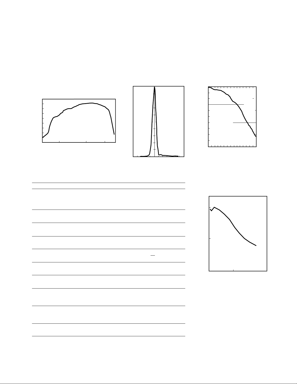
83440B Responsivity vs Wavelength
Wavelength (nm)
Pulse System Response
13
1
.5
FWHM 50 ps
Relative voltage
0
–100
0 100
Time (ps)
Response of a Agilent 83440B lightwave
detector on an Agilent 54124 oscilloscope
due to a 2 ps pulsed YAG laser.
83440B
Frequency Response
0
–3 dB
elec
–5
electrical
dB
–10
0
–3 dB
opt
3
6 9
Frequency (GHz)
Deconvolved frequency response from
2 ps pulsed YAG laser measured by
Agilent 83440B and Agilent 54124 oscilloscope.
Typical 83440B
Saturation Characteristics
1
0.5
Relative Electrical Bandwidth
0
0 500
Peak Optical Power (mW)
5 ps pulse width (1060 nm)
0
–1
dB
–2
optical
–3
–4
–5
3
Agilent 83440C
Specifications and Characteristics
Specifications describe the instrument’s warranted performance over the temperature range
0 to 55°C (except where noted). Supplemental Characteristics are intended to provide information
useful in applying the instrument by giving typical but non-warranted performance parameters.
These are denoted as “typical,” “nominal,” or “approximate.”
Typical Response Curves
Time Domain Frequency Domain
Conversion Gain
1,4
(min, into 50 Ω load) DC Responsivity
1,4
(min)
1300 nm: 35 V/W 1550 nm: 32.5 V/W 1300 nm 1550 nm
0.70 A/W 0.65 A/W
–3.1 dB
2
–3.7 dB
2
Pulse Width
3, 4,10
Bandwidth
3,4
< 22 ps FWHM6(calculated:FWHM=0.44/BW
opt
≈0.312/BW
el
) dc to >20 GHz (-3dB optical)
Rise/Fall Time
7,10 (10-90%)
<24ps (calculated)
System Aberrations
4,13
(response to 2 ps FWHM pulse)
10% peak-to-peak max, 5% typical
Noise
5,11
Noise Equivalent Power
5,11
3.7 µW RMS max, equivalent optical noise power < 18 pW/ √Hz typical
Dark Current
11
20 nA max, 3 nA typical
Maximum Safe Input Optical Power
10 mW (Peak) +10 dBm (Peak)
Maximum Operating Input Optical Power (Compression Point)
2 mW (Peak) +3 dBm (Peak)
See saturation chart for pulsed power characteristics
Input Optical Reflection
8
Input Optical Return Loss
8
(HMS-10 optical connector) (HMS-10 optical connector)
0.05% (1250-1600 nm) >33 dB (1250-1600 nm)
Wavelength Spectral Response
4
1000 nm - 1600 nm
See Notes, page 7
83440C Uncorrected
Pulse System Response
1
83440C Responsivity vs Wavelength
.8
.7
.6
.5
.4
.3
.2
Responsivity (A/W)
.1
0
850 1050 1300 1550
.5
Relative voltage
FWHM 20.3 ps
Wavelength (nm)
0
–100
0 100
Time (ps)
Response of a Agilent 83440C lightwave
detector on an Agilent 54124 oscilloscope
due to a 2 ps pulsed YAG laser.
13
83440C
Frequency Response
0
–3 dB
–5
electrical
dB
elec
–3 dB
0
–1
dB
–2
optical
opt
–3
–4
–10
10
0
20 30
–5
Frequency (GHz)
Deconvolved frequency response from
2 ps pulsed YAG laser measured by
Agilent 83440C and Agilent 54124 oscilloscope.
Typical 83440C
Saturation Characteristics
1
0.5
Relative Electrical Bandwidth
0
0 500
Peak Optical Power (mW)
5 ps pulse width (1060 nm)

4
Time Domain Frequency Domain
Conversion Gain
1,4
(min into 50 Ω load) DC Responsivity
1,4
(min)
1300 nm: 20 V/W 1550 nm: 15 V/W 1300 nm 1550 nm
0.3 A/W 0.3 A/W
–8 dB
2
–10.5 dB
2
Pulse Width
4,10,14
(calculated:FWHM=0.44/BW
opt
≈0.312/BW
el
) Bandwidth
4,12,14
< 13 ps FWHM
6
dc to 30 GHz nominal (-3dB optical)
Rise/Fall Time
7,10
(10-90%)
<16 ps (calculated)
System Aberrations
4,13
(response to 2 ps FWHM pulse)
20% peak-to-peak max, <12% typical
Noise
5,11
Noise Equivalent Power
5,11
8.1 µW RMS max, equivalent optical noise power < 18 pW/ √Hz typical
Dark Current
11
20 nA max, 4 nA typical
Maximum Safe Input Optical Power
10 mW (Peak) +10 dBm (Peak)
Maximum Operating Input Optical Power (Compression Point)
2 mW (Peak) +3 dBm (Peak)
See saturation chart for pulsed power characteristics
Input Optical Reflection
8
Input Optical Return Loss
8
(HMS-10 optical connector) (HMS-10 optical connector)
0.10 % (1250-1600 nm) >30 dB (1250-1600 nm)
Wavelength Spectral Response
4
1000 nm - 1600 nm
Typical Response Curves
See Notes, page 7
Relative voltage
83440D
Specifications describe the instrument’s warranted performance over the temperature range
0 to 55°C (except where noted). Supplemental Characteristics are intended to provide information
useful in applying the instrument by giving typical but non-warranted performance parameters.
These are denoted as “typical,” “nominal,” or “approximate.”
Agilent 83440D
Specifications and Characteristics
Uncorrected System Pulse Response
1
83440D Responsivity vs Wavelength
0.5
0.4
0.3
0.2
Responsivity (A/W)
0.1
0
850 1000 1300 1550
.5
FWHM 14.7 ps
Wavelength (nm)
0
–50
0
50
Time (ps)
Response of a Agilent 83440D lightwave
detector on an Agilent 54124 oscilloscope
due to a 2 ps pulsed YAG laser.
13
83440D Frequency Response
0
–3 dB
elec
–5
electrical
dB
–10
10
0
Deconvolved frequency response from
2 ps pulsed YAG laser measured by
Agilent 83440D and Agilent 54124 oscilloscope.
Frequency (GHz)
–3 dB
20 30
opt
0
–1
dB
optical
–2
–3
–4
–5
40
100
Typical 83440D
Saturation Characteristics
1
0.5
Relative Electrical Bandwidth
0
0 200 400
Peak Optical Power (mW)
5 ps pulse width (1060 nm)

Using the Agilent 83440B/C/D
Lightwave Converter
O/E Conversion Process
The 83440 detects the modulated
baseband signal from the lightwave
carrier, converting it to an electrical
signal for processing. The resultant
electrical signal can be analyzed in
the time domain or frequency domain
using electrical oscilloscopes, signal
analyzers, and network analyzers.
The 83440B/C/D are DC coupled
receivers. For proper operation, a
DC path to ground is necessary at
the RF output. When using the 83440
with an AC-coupled instrument
(except opt 050), a bias tee such as
the 11612A is required to supply dc
bias return path. Alternatively, an
attenuator on the output may be
used to provide a dc bias return path.
Supplying +15V to the
83440
Depending on the instruments that
the Agilent 83440 will be used with,
there are several possible configurations to supply the needed +15V bias
voltage to the 83440:
86100B: Use the 83440-60004 cable
to connect to the +15V supply
at the rear of the 86100B
Agilent Network Analyzers with
Probe Power: Use the 83440-60006
cable to connect to the Probe Power
Port of the network analyzer.
87421A Power Supply: Use the
83440-60009 cable in series with the
83440-60004 to connect to the power
supply
11899A Probe Power Supply: Use
the 83440-60006 cable to connect to
the stand-alone probe power supply.
General Purpose Variable Power
Supply: Use the 83440-60005 cable
in series with the 83440-60004 cable.
5
General
RF Connector Agilent 83440B/C (3.5 mm [m]) or 83440D (2.4 mm [m]), 50Ω
ESD Susceptibility at RF Pin
9
200 V
DC Bias Voltage +10 to +15V dc required
Power Consumption < 18 mVA
Weight 0.14 kg (0.31 lb)
Operating Temperature 0-55 deg C
Compatible Fiber 9/125 single mode fiber
Photodiode Package Hermetically sealed PIN-diode
Output Impedance Unterminated (50Ω terminated for Agilent 83440B Opt 050)
Calibration Recommended calibration interval is two years.
See Notes, page 7
Mechanical
10.5
(0.41)
15
(0.59)
6
(0.24)
45
(1.8)
16.8
(0.66)
105 ±0.2
(4.13)
All dimensions in mm (inches). Weight 0.14 kg (0.31 lb)
All tolerances ± 0.1 unless otherwise noted
21
(0.83)
30
(1.2)
8.0
(5/16) across flats
Bias Port
Center conductor: +10 to +15 vdc
Outer conductor: Common
83440B/C/D
Connectors
Optical Input: Electrical Output:
Specify optical input connector option 3.5 mm (83440B/C)
when ordering Agilent 83440B/C/D. 2.4 mm (83440D)
81000 AI Diamond HMS-10 DC Bias Input: Quick connect
81000FI FC/PC connector (LEMO) bias port
81000 SI DIN 47256 connector
81000 VI ST connector
81000 KI SC connector
ESD Sensitive Parts
9
The 83440 features a captive RF connector
cap to protect the RF center pin from electrostatic discharge (ESD). Use proper ESD precautions when working with RF and bias ports.
Keep RF port capped when not in use.
Physical Characteristics
6
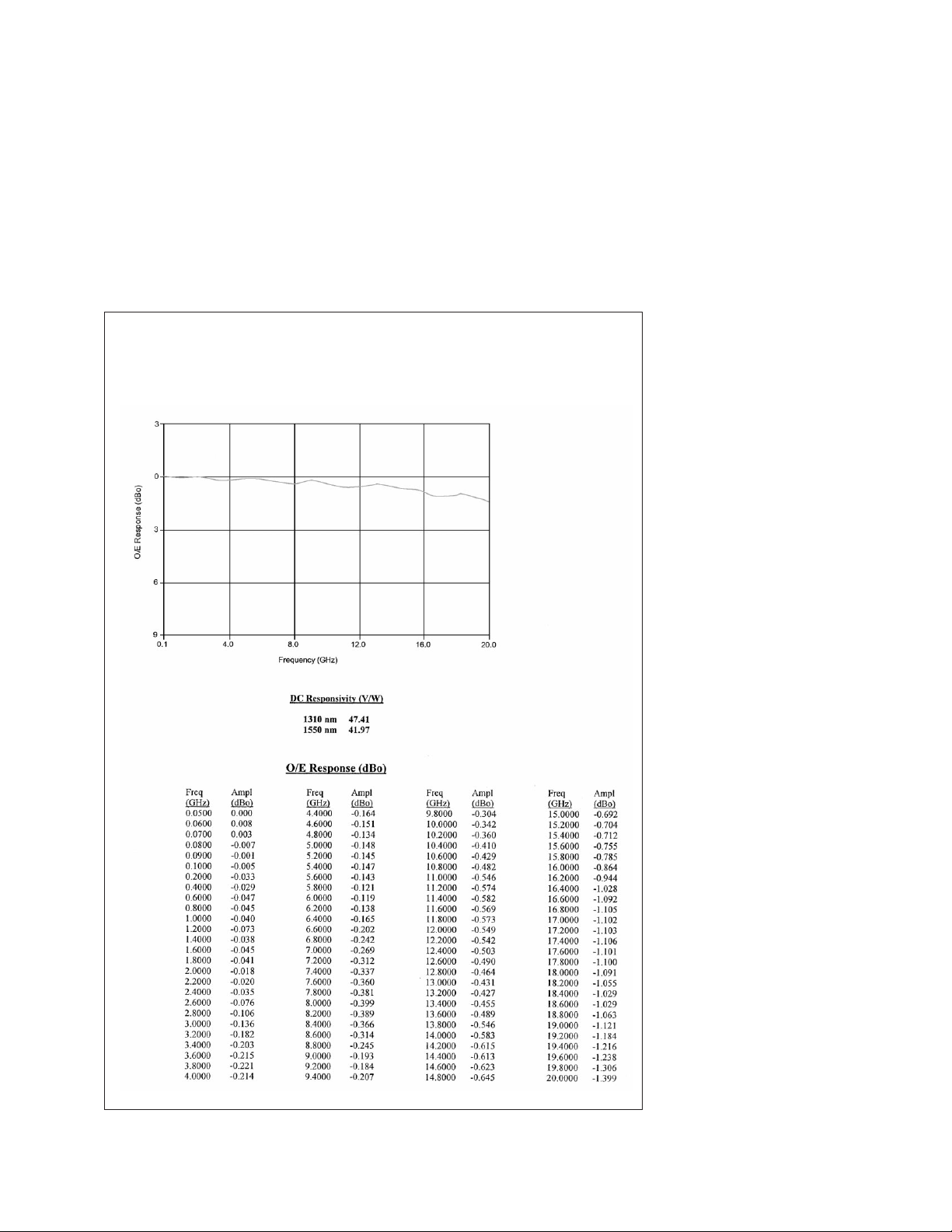
Each 83440 is shipped with instrument-specific frequency response and conversion gain (dc responsivity) data.
83440C
S/N: XXXXAXXXXX
Frequency Response Relative to DC
Shipping Contents
• One 83440 Lightwave Detector with response data sheet (example shown below)
• User specified optical connector adapter
• Three dc bias cables (83440-60004, 83440-60005, 83440-60006)

Agilent 83440B DC-6 GHz Lightwave Converter
83440B-050, 50Ω termination for use with SDH/SONET filters
Agilent 83440C DC-20 GHz Lightwave Converter
Agilent 83440D DC-30 GHz Lightwave Converter
Note: All 83440 orders must specify an optical connector option.
Recommended Accessories
87421A External 15V fixed power supply
11899A External probe power supply
8493C-003, 006 3.5 mm fixed attenuators (3 dB and 6 dB respectively)
11901D 2,4 mm (f) to 3.5 mm (m) coax adapter
1250-1391 SMB-tee
11612A 3.5 mm bias network (45 MHz–26.5 GHz)
5952-9654 Fiber Optics Handbook
DC Bias Cables
83440-60004 SMB (f) to quick connect (LEMO)
83440-60005 SMB (m) to bare wire (ground = black, +15V = clear)
83440-60006 3-pin half-round (f) to quick connect (LEMO)
83440-60009 9-pin D-sub (m) to SMB (m)
Other Agilent O/E Converters
Agilent 11982A DC–15 GHz amplified converter. 300 V/W conversion gain.
Product Overview lit. no. 5966-1583E.
Agilent 83410C 300 kHz–3 GHz amplified receiver (62.5/125 µm fiber).
Technical Specifications lit. no. 5988-4308EN.
Agilent 83411A 300 kHz–6 GHz receiver (62.5/125 µm fiber).
Technical Specifications lit. no. 5988-4308EN.
Agilent 83411B 300 kHz–6 GHz amplified receiver (62.5/125 µm fiber).
Technical Specifications lit. no. 5988-4308EN.
Agilent 83412A 300 kHz–3 GHz amplified receiver (850 nm) (62.5/125 µm fiber).
Technical Specifications lit. no. 5988-4308EN.
Agilent 83434A 10 Gb/s lightwave clock and data receiver.
Product Overview lit. no. 5968-9251E.
Agilent 83446A/B 2.4 Gb/s lightwave clock and data receiver.
Product Overview lit. no. 5962-1682E.
Notes
1
Stated specs from 83440B/C /D into 50Ω load.
2
For an O/E device, responsivity (dB) = 20log
[
responsivity A/W
]
1 A/W
3
Measured on 8703A lightwave component analyzer. Frequency response verified by deconvolving impulse response of 83440C on 54124 oscilloscope due to a 2 ps pulse YAG laser.
4
See typical performance trace.
5
Thermal noise limited; equivalent optical power limited by 50 Ω input impedance.
6
Full-Width Half-Max.
7
Calculated from bandwidth measurements; tr =
.48
,(≈
.34
) Calculation assumes
Gaussian pulse.
BW
opt BWelec
8
Optical connector limited.
9
ESD susceptibility limited to RF connector center pin. Overall package (other than bias port and
RF connector) withstands >25,000 V ESD.
10
Impulse response calculations verified using 2 ps pulsed YAG laser.
11
At room temperature ( 23°C ± 3°C)
12
All 83440D units are tested for 30 GHz minimum bandwidth. Measured frequency response
data is supplied with each unit.
13
Uncorrected System aberrations include oscilloscope response and source laser aberrations
from 2 ps pulsed YAG laser system. Slower pulse width will generate lower aberration levels;
high 83440D detector bandwidth can excite 50 GHz oscilloscope response.
14
83440D test system consists of 2-3 ps compressed Nd:YAG laser and 54124 50 GHz
digitizing oscilloscope. 83440D frequency response is derived from Fourier transform after
correcting for oscilloscope and input pulse frequency response. System verified with YAG
heterodyne.
7
Ordering Information

Agilent Technologies’
Test and Measurement Support, Services, and Assistance
Agilent Technologies aims to maximize the value you receive, while minimizing your risk and
problems. We strive to ensure that you get the test and measurement capabilities you paid for and
obtain the support you need. Our extensive support resources and services can help you choose the
right Agilent products for your applications and apply them successfully. Every instrument and
system we sell has a global warranty. Support is available for at least five years beyond the
production life of the product. Two concepts underlie Agilent’s overall support policy: “Our Promise”
and “Your Advantage.”
Our Promise
Our Promise means your Agilent test and measurement equipment will meet its advertised
performance and functionality. When you are choosing new equipment, we will help you with
product information, including realistic performance specifications and practical recommendations
from experienced test engineers. When you use Agilent equipment, we can verify that it works
properly, help with product operation, and provide basic measurement assistance for the use of
specified capabilities, at no extra cost upon request. Many self-help tools are available.
Your Advantage
Your Advantage means that Agilent offers a wide range of additional expert test and measurement
services, which you can purchase according to your unique technical and business needs. Solve
problems efficiently and gain a competitive edge by contracting with us for calibration, extra-cost
upgrades, out-of-warranty repairs, and on-site education and training, as well as design, system
integration, project management, and other professional engineering services. Experienced Agilent
engineers and technicians worldwide can help you maximize your productivity, optimize the return on
investment of your Agilent instruments and systems, and obtain dependable measurement accuracy
for the life of those products.
By internet, phone, or fax, get assistance with all your test & measurement needs.
Online assistance:
www.agilent.com/comms/lightwave
Phone or Fax
United States:
(tel) 1 800 452 4844
Canada:
(tel) 1 877 894 4414
(fax) (905) 282 6495
China:
(tel) 800-810-0189
(fax) 1-0800-650-0121
Europe:
(tel) (31 20) 547 2323
(fax) (31 20) 547 2390
Japan:
(tel) (81) 426 56 7832
(fax) (81) 426 56 7840
Korea:
(tel) (82-2) 2004-5004
(fax)(82-2) 2004-5115
Latin America:
(tel) (305) 269 7500
(fax) (305) 269 7599
Taiwan:
(tel) 080-004-7866
(fax) (886-2) 2545-6723
Other Asia Pacific Countries:
(tel) (65) 375-8100
(fax) (65) 836-0252
Email: tm_asia@agilent.com
Product specifications and descriptions in this document subject to change without notice.
© 1991, 1992, 1996, 2000, 2001, 2002 Agilent Technologies, Inc.
Printed in USA August 29, 2002
5988-7788EN
www.agilent.com/find/emailupdates
Get the latest information on the
products and applications you select.
 Loading...