


Agilent Technologies 83236B
PCS Interface
Operating Manual
Serial Numbers
This manual applies directly to instruments with serial
number prefix 3711J. For additional important information
about serial numbers, see Serial Numbers on page 144.
Agilent Part No. 83236-90102
Printed in Japan
April 2000
4th Edition
i

Copyright © Agilent Technologies, Inc. 1996, 1997, 2000
Notice Information contained in this document is subject to change without notice.
This document contains proprietary information that is protected by copyright. All
rights are reserved. No part of this document may be photocopied, reproduced, or,
translation to another language without the prior written consent of
Agilent Technologies, Inc.
Kobe Wireless Test Development
Agilent Technologies Japan, Limited.
1-3-2, Murotani, Nishi-ku, Kobe-shi,
Hyogo, 651-2241 Japan
ii

Manual
Printing
History
The manual printing and part number indicate its current edition. The printing date
changes when a new edition is printed. (Minor corrections and updates that are
incorporated at reprint do not cause the date to change.) The manual part number
changes when extensive technical changes are incorporated.
November 1996................................................................................ 1st Edition
March 1997 ..................................................................................... 2nd Edition
October 1997....................................................................................3rd Edition
April 2000 ........................................................................................4th Edition
iii

Certification Agilent Technologies certifies that this product met its published specifications at
the time of shipment from the factory. Agilent Technologies further certifies that
its calibration measurements are traceable to the United States National Institute of
Standards and Technology, to the extent allowed by the Institution's calibration
facility, or to the calibration facilities of other International Standards Organization
members.
Warranty This Agilent Technologies instrument product is warranted against defects in
material and workmanship for a period of one year from the date of shipment,
except that in the case of certain components listed in Specifications of this manual,
the warranty shall be for the specified period. During the warranty period, Agilent
Technologies will, at its option, either repair or replace products which prove to be
defective.
For warranty service or repair, this product must be returned to a service facility
designated by Agilent Technologies. Buyer shall prepay shipping charges to
Agilent Technologies and Agilent Technologies shall pay shipping charges to
return the product to Buyer. However, Buyer shall pay all shipping charges, duties,
and taxes for products returned to Agilent Technologies from another country.
Agilent Technologies warrants that its software and firmware designated by
Agilent Technologies for use with an instrument will execute its programming
instruction when properly installed on that instrument. Agilent Technologies does
not warrant that the operation of the instrument, or software, or firmware will be
uninterrupted or error free.
Limitation Of
Warranty
Exclusive
Remedies
The foregoing warranty shall not apply to defects resulting from improper or
inadequate maintenance by Buyer, Buyer-supplied software or interfacing,
unauthorized modification or misuse, operation outside of the environmental
specifications for the product, or improper site preparation or maintenance. No
other warranty is expressed or implied. Agilent Technologies specifically
disclaims the implied warranties of merchantability and fitness for a particular
purpose.
The remedies provided herein are buyer's sole and exclusive remedies. Agilent
Technologies shall not be liable for any direct, indirect, special, incidental, or
consequential damages, whether based on contract, tort, or any other legal theory.
Assistance Product maintenance agreements and other customer assistance agreements are
available for Agilent Technologies products.
For any assistance, contact your nearest Agilent Technologies Sales and Service
Office. Addresses are provided at the back of this manual.
iv

Safety
Summary
The following general safety precautions must be observed during all phases of
operation, service, and repair of this instrument. Failure to comply with these
precautions or with specific WARNINGS elsewhere in this manual may impair
the protection provided by the equipment. In addition it violates safety standards
of design, manufacture, and intended use of the instrument. The Agilent
Technologies assumes no liability for the customer's failure to comply with these
requirements.
NOTE: Agilent Technologies 83236B complies with INSTALLATION CATEGORY II and
POLLUTION DEGREE 2 in IEC1010-1. Agilent 83236B is an INDOOR USE product.
NOTE: LEDs in the Agilent 83236B are Class 1 in accordance with IEC 825-1.
CLASS 1 LED PRODUCT
Ground the Instrument
To avoid electric shock hazard, the instrument chassis and cabinet must be
connected to a safety earth ground by the supplied power cable with earth blade.
DO NOT Operate In An Explosive Atmosphere
Do not operate the instrument in the presence of flammable gasses or fumes.
Operation of any electrical instrument in such an environment constitutes a
definite safety hazard.
Keep Away From Live Circuits
Operating personnel must not remove instrument covers. Component replacement
and internal adjustments must be made by qualified maintenance personnel. Do
not replace components with the power cable connected. Under certain
conditions, dangerous voltages may exist even with the power cable removed. To
avoid injuries, always disconnect power and discharge circuits before touching
them.
DO NOT Service Or Adjust Alone
Do not attempt internal service or adjustment unless another person, capable of
rendering first aid and resuscitation, is present.
v

DO NOT Substitute Parts Or Modify Instrument
Because of the danger of introducing additional hazards, do not install substitute
parts or perform unauthorized modifications to the instrument. Return the
instrument to a Agilent Technologies Sales and Service Office for service and
repair to ensure that safety features are maintained.
Dangerous Procedure Warnings
Warnings, such as the example below, precede potentially dangerous procedures
throughout this manual. Instructions contained in the warnings must be followed.
WARNING: Dangerous voltages, capable of causing death, are present in this instrument. Use
extreme caution when handling, testing, and adjusting this instrument.
Safety
Symbols
General definitions of safety symbols used on equipment or in manuals are listed
below.
Instruction manual symbol: the product is marked with this symbol when it is
!
necessary for the user to refer to the instruction manual.
Alternating current.
Direct current.
|
On (Supply).
Ο
Off (Supply).
In position of push-button switch.
Out position of push-button switch.
WARNING: This WARNING sign denotes a hazard. It calls attention to a procedure, practice,
condition or the like, which, if not correctly performed or adhered to, could result in
injury or death to personnel.
CAUTION: This CAUTION sign denotes a hazard. It calls attention to a procedure, practice, condition
or the like, which, if not correctly performed or adhered to, could result in damage to or
destruction of part or all of the product.
NOTE: NOTE denotes important information. It calls attention to a procedure, practice, condition
or the like, which is essential to highlight.
vi

vii

Herstellerbescheinigung
GERXUSCHEMISSION
LpA < 70 dB
am Arbeitsplatz
normaler Betrieb
nach DIN 45635 T. 19
Manufacturer’s Declaration
ACOUSTIC NOISE EMISSION
LpA < 70 dB
operator position
normal operation
per ISO 7779
viii

In this Manual This manual describes general information, function, operation, and specifications
of the Agilent 83236B PCS Interface. The following chapters are included in this
manual.
Appendix 1, General Information
This chapter provides a product overview and describes the furnished accessories,
options, and front and rear panels.
Appendix 2, Installation
This chapter describes the steps for configuring the PCS Interface.
Appendix 3, Programming the PCS Interface using GPIB Control
This chapter describes how to control the PCS Interface using GPIB commands.
Appendix 4, GPIB Commands
This chapter describes the remote operation of the PCS Interface using GPIB.
Appendix 5, Specifications
This chapter describes the specifications of the PCS Interface.
Appendix A, Frequency Conversion Tables
Appendix A provides the frequency conversion tables used internally by the PCS
Interface’s CPU to determine the Test Set’s frequencies.
Appendix B, Manual Changes
Appendix B provides a manual change history and information about serial
numbers.
Appendix C, Error Messages
This section describes the error messages generated by the PCS Interface.
Glossary
This section defines terms used throughout this manual.
ix

x

Contents
1 General Information
Introduction 16
Incoming Inspection 18
Furnished Accessories 19
Power Cable 20
Options 22
Front Panel 24
Rear Panel 26
Other Information 29
2 Installation
Introduction 32
When Used with Agilent 8924C and Controlled via Serial Port for
CDMA Subscriber Unit Tests 34
When Used with Agilent 8924C and Controlled via GPIB for
CDMA Subscriber Unit Tests 37
When Used with Agilent 8920B and Controlled via Serial Port for
TDMA Subscriber Unit Tests 40
When Used with Agilent 8920A,B and Controlled via GPIB for
TDMA Subscriber Unit Tests 45
When Used with Agilent 8921A for CDMA Base Stations Tests 50
When Used with Agilent 8921A for TDMA Base Stations Tests 54
11

Contents
Load and Run the Connectivity Test Software (Option 001 or
002) 59
Where to go next 64
3 Programming the PCS Interface using GPIB Control
Introduction 66
Overview of Programming Issues 67
PCS Interface Programming Guide 75
Test Procedure Flow 76
Initialize the System 77
Set Up and Measure 79
4GPIB Commands
Introduction 92
The Syntax of Program Messages 94
Common Commands 98
COMPensation Subsystem 100
RF Subsystem 106
RX Subsystem 108
SYSTem Subsystem 113
TX Subsystem 114
12

Contents
GPIB Command Summary 121
5 Specifications
Introduction 124
Generator Output Path 125
Analyzer Input Path 128
Reference Specifications 131
Remote Control 131
Connectors 132
General Characteristics 135
A Frequency Conversion Tables
Frequency Conversion for Signal Generation 138
B Manual Changes
Introduction 142
Manual Changes 143
Serial Numbers 144
Change 1 145
C Error Messages
13

Contents
Error Message 154
Glossary 161
14

1G
General Information
eneral Information
What’s included in this chapter:
• Introduction
• Furnished Accessories
• Options
• Front Panel
• Rear Panel
15

Chapter 1, General Information
Introduction
Introduction
Figure 1 Agilent 83236B PCS Interface
The Agilent 83236B PCS Interface extends the time division multiple access
(TDMA) and code division multiple access (CDMA) measurement capability of
the Agilent 8920A,B, Agilent 8921A, and Agilent 8924C Test Sets to the 1710 to
1990 MHz frequency range. This frequency range covers the International (1710
to 1880 MHz), Korean (1715 to 1870 MHz), and North American (1850 to
1990 MHz) Personal Communications Service (PCS) bands. Table 1 shows the
supported equipment combinations and the type of unit-under-test (UUT).
Table 1 Supported configuration and UUTs
UUT Type Test Set
TDMA Base Station Agilent 8921A Agilent 83204A
TDMA Subscriber Unit Agilent 8920A,B Agilent 83206A
CDMA Base Station Agilent 8921A Agilent 83203B or Agilent 83205A
CDMA Subscriber Unit Agilent 8924C Not required
1.The combination of the Agilent 8921A and 83204A composes the Agilent 8921A option 500.
2.Can be used with Agilent 8920B only. The combination of the Agilent 8920B and 83206A composes
the Agilent 8920B option 800.
3.The combination of the Agilent 8920A and 83201A composes the Agilent 8920D.
4.The combination of the Agilent 8920B and 83201B composes the Agilent 8920B option 500.
5.The combination of the Agilent 8921A and 83205A composes the Agilent 8921A option 600.
International, Korea, and North
American PCS Bands
Cellular Adapter
1
2
5
North American
PCS Band only
Agilent 83201A
Agilent 83201A3,B
—
4
16

Chapter 1, General Information
Introduction
Power measurement accuracy and speed are maintained at PCS band frequencies
with an internal power meter for measurements on CW, CDMA, and TDMA
signals.
The PCS Interface has no front panel “controls” and cannot be used manually.
Control of the PCS Interface is via GPIB using an external controller or the Test
Set’s internal IBASIC controller, or via the serial port by the Agilent 8924C
whose firmware revision is A.05.00 and above or Agilent 8920B option 800
whose firmware revision is B.05.00 and above.
Most of this manual is dedicated to assisting you in the integration, GPIB
programming, and control of the PCS Interface.
NOTE: Refer to the Agilent 8924C User’s Guide or Agilent 8920B User’s Guide for the operation
of the Agilent 83236B controlled via the serial port.
Conventions Used The Agilent 83236B PCS Interface can be used with a variety of Test Sets and a
variety of Cellular Adapters.
•Test Sets
• Agilent 8920A, B
• Agilent 8921A
• Agilent 8924C
• Cellular Adapters
• Agilent 83201A,B
• Agilent 83203B
• Agilent 83204A
• Agilent 83205A
• Agilent 83206A
To simplify things, the term Test Set will be used throughout this manual to refer
to any Agilent 892NX, the term Cellular Adapter to refer to any Agilent 8320NX,
and the term PCS Interface to refer to the Agilent 83236B PCS Interface. The
combination of the Test Set, Cellular Adapter, and PCS Interface will be referred
to as the Test System.
In some instances, TX will be used in place of the word transmitter, and RX will
be used in place of the word receiver; UUT will be used as an abbreviation for
unit-under-test.
17

Chapter 1, General Information
Incoming Inspection
Incoming Inspection
WARNING: To avoid hazardous electrical shock, do not turn on the PCS Interface when there are
signs of shipping damage to any portion of the outer enclosure (for example, covers,
panel, or display).
Inspect the shipping container for damage. If the shipping container or cushioning
material is damaged, it should be kept until the contents of the shipment have
been checked for completeness and the PCS Interface has been checked
mechanically and electrically. The contents of the shipment should be as listed in
table 2 on page 19. If the contents are incomplete, if there is mechanical damage
or defect, or if the system does not pass the power-on self tests, notify the nearest
Agilent Technologies office. If the shipping container is damaged, or the
cushioning material shows signs of unusual stress, notify the carrier as well as the
Agilent Technologies office. Keep the shipping materials for the carrier's
inspection.
18

Furnished Accessories
The following accessories are furnished with the PCS Interface.
Table 2 Included Accessories
Name Qty. Part/Product Number
GPIB Cable (0.5 m) 1 Agilent 10833D
Serial Cable 1 Agilent p/n 83236-61609
N-BNC Cable 2 Agilent p/n 83236-61603
SMA-SMC Cable 1 Agilent p/n 83215-61643
Chapter 1, General Information
Furnished Accessories
SMC-SMC Cable 1 Agilent p/n 83215-61644
BNC-BNC Cable 1 Agilent p/n 8120-1839
BNC L-type adapter 2 Agilent p/n 1250-0076
BNC T-type adapter 1 Agilent p/n 1250-0781
Operation Manual (this manual) 1 Agilent p/n 83236-90102
Read Me First — Cable Connections for the
PCS Interface
Front Cover 1 Agilent p/n 83201-61013
Power Cable
1. The part number depends on where the instrument is used, see "Power Cable" on
page 20.
1
1 Agilent p/n 83236-90130
1
19

Chapter 1, General Information
Power Cable
Power Cable
In accordance with international safety standards, this instrument is equipped
with a three-wire power cable. When connected to an appropriate ac power outlet,
this cable grounds the instrument frame. The type of power cable shipped with
each instrument depends on the country of destination. Refer to figure 2 on page
21 for the part numbers of the power cables available.
20

Chapter 1, General Information
Power Cable
WARNING: For protection from electrical shock, the power cable ground must not be defeated.
The power plug must be plugged into an outlet that provides a protective earth
ground connection.
Figure 2 Power Cable Supplied
21

Chapter 1, General Information
Options
Options
The following options can be used with the PCS Interface.
001
Utility Software on PCMCIA Card
002 Utility Software on EPSON Memory Card
1AB Bench Top Kit
AX4 Rack Flange Kit
Option 001 — Utility Software on PCMCIA Card
Provides the Utility Software memory card which includes the Manual Control
and Connectivity Test Programs (for Agilent 8920B and Agilent 8924C). N(f)BNC(m) adapter and N(m)-BNC(f) adapter are also provided for the Connectivity
Test Program.
Table 3 Included Accessories (Option 001)
Name Qty. Part/Product Number
Utility Software 1 Agilent p/n 83236-61002
N(f)-BNC(m) Adapter 1 Agilent p/n 1250-2789
N(m)-BNC(f) Adapter 1 Agilent p/n 1250-0780
Manual Control Software User’s Guide 1 Agilent p/n 83236-90110
Option 002 — Utility Software on EPSON Memory Card
Provides the Utility Software memory cards which include the Manual Control,
Connectivity, and CDMA/PCS Base Station Test Programs (for Agilent 8920A
and Agilent 8921A). N(f)-BNC(m) adapter and N(m)-BNC(f) adapter are also
provided for the Connectivity Test Program.
22

Table 4 Included Accessories (Option 002)
Name Qty. Part/Product Number
Utility Software 1 Agilent p/n 83236-61001
N(f)-BNC(m) Adapter 1 Agilent p/n 1250-2789
N(m)-BNC(f) Adapter 1 Agilent p/n 1250-0780
Manual Control Software User’s Guide 1 Agilent p/n 83236-90110
Chapter 1, General Information
Options
CDMA/PCS Base Station Test Software
User’s Guide
Option 1AB — Bench Top Cabinet Kit
This kit is used to stack a 19-inch-wide instrument, such as the Agilent 8924C
CDMA Mobile Station Test Set, on the Agilent 83236B. Rack mounting
hardware is included.
For the instructions on how to mount the PCS Interface, refer to the Agilent
83236A,B PCS Interface Option 1AB Bench Top Kit Installation Instruction
included with the kit.
Table 5 Included Accessories (Option 1AB)
Name Qty. Part/Product Number
Bench Top Cabinet Kit 1 Agilent p/n 83236-60022
Option AX4 — Rack Flange Kit
This kit mounts the instrument in a rack with 482.6 mm (19 in) spacing.
For the instructions on how to rack mount the PCS Interface, refer to the
Agilent 83236A,B PCS Interface Option AX4 Rack Flange Kit Rack Mount
Installation Instructions included with the kit.
1 Agilent p/n 83236-90121
Table 6 Included Accessories (Option AX4)
Name Qty. Part/Product Number
Rack Flange Kit 1 Agilent p/n 83236-60021
23

Chapter 1, General Information
Front Panel
Front Panel
1
Figure 3 Front Panel
1. Line Switch The power switch. The On position is | and the Off position is Ο. In the On
position, power is supplied and the indicator above the switch is lit.
2. FROM DUPLEX
OUT
3. TO ANT IN Connects to the ANT IN port of a Test Set. (Connector type: Type N (F))
Connects to the DUPLEX OUT port of a Test Set. (Connector type: Type N (F))
2
3
4
5
24

Chapter 1, General Information
Front Panel
Connects to the transmit/receive antenna port of a radio.
4. RF IN/OUT
CAUTION: The maximum allowable average power to the RF IN/OUT port depends on the unit-under-
(Connector type: Type N (F))
test as follows. Use an external attenuator if you are uncertain.
Subscriber Unit Test
Single carrier TDMA and FM: 10 Watts
CDMA: 5 Watts
Base Station Test
Single carrier TDMA and FM: 10 Watts
CDMA: 1 Watt
CAUTION: Peak instantaneous signals greater than 30 volts will damage internal circuitry.
Connects to the receive antenna port of a radio. (Connector type: Type N (F))
5. RF OUT only
CAUTION: Do not input a continuous signal greater than +23 dBm (200 mW). Doing so may damage
internal circuits.
25

Chapter 1, General Information
Rear Panel
Rear Panel
1234
Figure 4 Rear Panel
1. GPIB Address
Selector
2. REF IN Reference frequency input port. The REF IN port connects to the 10 MHz
3. REF OUT Reference frequency output port. The REF OUT port may be used as a 10 MHz
4. EXT TRIG IN External trigger input. EXT TRIG IN is used to trigger power measurements of
The GPIB address selector specifies the GPIB interface address. The address
selector consists of the switches A1 to A5. The switch A1 is the least significant
bit (1) and A5 the most significant bit (16). For example, you may set the switches
A1, A2, and A5 ON (1) to specify 19 as your GPIB address.
The
GPIB/Ser switch sets whether the GPIB port or SERIAL PORT is used to
control the PCS Interface.
reference source. (Connector type: BNC (F))
source for other equipment. (Connector type: BNC (F))
TDMA bursted signals. It connects to the FRAME CLK OUT port of the Cellular
Adapter when the UUT is the TDMA type. (Connector type: SMC (M))
5
678
5. DET OUT Detector output. DET OUT can be used for power measurements of CDMA
subscriber units. (Connector type: SMC (M))
26

Chapter 1, General Information
Rear Panel
6. GPIB Interface The GPIB interface connects to an external controller to enable the control of the
PCS Interface. In most cases, this control is provided by a Test Set.
NOTE: To enable this GPIB Interface, set the GPIB/Ser switch of the GPIB Address Selector to
the “GPIB” side (left side as viewed from the rear panel).
This interface conforms to IEEE 488.2 and has the following functions:
Table 7 GPIB Functions
Codes Functions
SH1 Full source handshake capability
AH1 Full accepter handshake capability
T8 Basic talker. No serial poll. No talk only mode. Unaddressed if MLA.
L4 Basic listener. No listen only mode. Unaddressed if MTA
SR0 No service request capability
RL1 Complete remote/local capability
PP0 No parallel poll capability
DC1 Full device clear capability
DT0 No device trigger capability
E2 Tri-state driver electronics
C0 No controller capability
27

Chapter 1, General Information
Rear Panel
7. SERIAL PORT This port is used for the Agilent 83236B to be controlled by the Agilent 8924C
whose firmware revision is A.05.00 and above or Agilent 8920B whose firmware
revision is B.05.00 and above.
NOTE: To enable this serial port, set the GPIB/Ser switch of the GPIB Address Selector to the
“Ser” side (right side as viewed from the rear panel).
8. Power Cord
Receptacle
The PCS Interface can operate from AC sources of 90 to 132 Vac and 198 to
264 Vac (47 to 63 Hz). No internal changes are necessary to select AC supply.
28

Other Information
Chapter 1, General Information
Other Information
Power
Requirements
The PCS Interface requires the following power source:
Voltage: 90 to 132 Vac, 198 to 264 Vac
Frequency: 47 to 63 Hz
Power: 100 VA maximum
Fuse The main fuse is located inside of the PCS Interface. The type and rating of this
fuse are as follows.
UL/CSA type, time delay, 3 A, 250 Vac
WARNING: The main fuse is not replaceable by the operator. Refer servicing to qualified
personnel.
Ventilation
Requirements
Instructions for
To ensure adequate ventilation, make sure that there is adequate clearance around
the PCS Interface.
For cleaning, wipe lightly with a soft damp cloth.
Cleaning
Calibration Cycle Contact your nearest Agilent Technologies service office.
29

Chapter 1, General Information
Other Information
30

2I
Installation
nstallation
Before attempting to make measurements or generate programs using the PCS
Interface, it is a good idea to follow the steps in this chapter. This will ensure that
the proper connections are made between the PCS Interface and other hardware
and will verify basic operation of the Test System.
Installation
31

Chapter 2, Installation
Introduction
Introduction
Chapter Overview Included in this chapter are steps for setting up the PCS Interface for the
following test configurations:
Table 8 PCS Interface Test Configurations
You will
control
the PCS
Interface
using...
Refer to...
If you are testing... And your Test Set Model is...
With Cellular
Adapter Model...
CDMA Subscriber Units Agilent 8924C
(Firmware: A.05.00 and above)
Agilent 8924C
(Firmware: Below A.05.00)
TDMA Subscriber Units Agilent 8920B
(Firmware: B.05.00 and above)
Agilent 8920B
(Firmware: Below B.05.00)
Agilent 8920A Agilent 83201A,B
CDMA Base Stations Agilent 8921A Agilent 83203B,
TDMA Base Stations Agilent 8921A Agilent 83201A,
Agilent 83206A Serial
Agilent 83201A,B,
Agilent 83206A
Agilent 83205A
Agilent 83204A
—
—GPIB
Serial
Port
Port
GPIB
page 34.
page 37.
page 40.
page 45.
page 50.
page 54.
32

Chapter 2, Installation
Introduction
The PCS Interface can be controlled by the following methods.
• Serial Port Control
The Agilent 8920B option 800 with firmware revision B.05.00 and above and Agilent
8924C with firmware revision A.05.00 and above can control the PCS Interface via
the serial port. Using this mode eliminates the need to control the PCS Interface
independently.
• GPIB Control
All of the above Test Sets can control the PCS Interface via the GPIB. You can use the
Manual Control Software or you can make programs to control the
PCS Interface.
You will be shown how to set up the equipment, make connections, and run a
software utility that verifies the connections and the instruments’ operation.
NOTE: When you want to use the PCS Interface with the Agilent 8924C on the work bench, the
PCS Interface’s Option 1AB Bench Top Kit is required to stack the Agilent 8924C on the
PCS Interface.
33

Chapter 2, Installation
When Used with Agilent 8924C and Controlled via Serial Port for CDMA Subscriber Unit
Tests
When Used with Agilent 8924C and Controlled via Serial Port for CDMA
Subscriber Unit Tests
NOTE: To control the PCS Interface via the serial port, the firmware of the Agilent 8924C must be
A.05.00 and above. Contact your nearest Agilent Technologies sales office for firmware
upgrade information.
Unpack the PCS
Interface and
Accessories
NOTE: This product passed all applicable electrical and mechanical inspections before it was
Follow these steps to prepare the Test System for setup:
1 Unpack the test equipment and accessories.
shipped from the factory. As soon as you receive it, check that it is not damaged and that
all accessories are present (see table 2 on page 19). Should this product be damaged or any
accessories be missing, contact your local Agilent Technologies sales office or the
company from which you purchased it.
2 Mount the PCS Interface into the PCS Interface’s option 1AB bench top kit.
3 Place the Agilent 8924C Test Set on the top of the PCS Interface.
34

Chapter 2, Installation
When Used with Agilent 8924C and Controlled via Serial Port for CDMA Subscriber Unit
Tests
Cable Connections Follow these steps to prepare the test equipment for use:
1 Set the GPIB Address Selector of the rear panel of the PCS Interface as follows.
GPIB/Ser switch Ser
GPIB address Any
2 Make the front and rear panel connections shown in figure 5.
3 Turn on the PCS Interface.
NOTE: The PCS Interface must be powered on and connected before the Agilent 8924C is powered
on. If the PCS Interface is not powered on first, the Agilent 8924C will not detect it.
4 Set up the Test Set.
a Turn on the Test Set.
b Press and release the SHIFT key then the TESTS key to access the CONFIGURE
screen.
c Position the cursor in the “PCS Intrfc Control” field, and press the knob to select
“On.”
d Turn the Test Set’s power off and then back on.
5 Perform the RF Generator Level Calibration.
a Press and release the SHIFT key then the TESTS key to access the CONFIGURE
screen.
b Position the cursor in the “RF Gen Level” field, and press the knob to start the
calibration.
35

Chapter 2, Installation
When Used with Agilent 8924C and Controlled via Serial Port for CDMA Subscriber Unit
Tests
From Agilent 8924 DUPLEX OUT
To Agilent 83236 FROM DUPLEX OUT
(Cable P/N 83236-61603)
SERIAL
From Agilent 8924 SERIAL
PORT
CURR
DC
To Agilent 83236 SERIAL
PORT
(Cable P/N 83236-61609)
POWE
DO NOT
!
GPI
PROTOCO EXT
RF IN/
!
MAX PWR
POWER
ONOFF
DUPLEX
83236B
PCS INTERFACE
!
MAX
ANTENN
FROM DUPLEX OUT TO ANT IN
From Agilent 8924 ANT IN
To Agilent 83236 TO ANT IN
(Cable P/N 83236-61603)
COMP
TIME
PARALLE
CELLSITE/TRIGGERS
AUX
10 MEAS
CDMA CALL
CALL ANS
USE DA
CDMA
k1’
CELL
CALL
k1
k2’
SPECTR
GEN
k2
k3’
k3
ANALOG
ASSIG
ENCO
RF
k4
RELE
k5
SPEC
RF
TEST SET
EXT
2nd DSPMODULAUD REF
MSG
END
HELP
REF
RANG
INCR
RX
LO HI
MSRP
TX
CURSO PU SH
DECO
RX
ACP
TXAF
SCOP
DUPL
CANCSHIFT
RF IN/OUT RF OUT only
FUNCTIO
PRINT
PRINT
DATA
METE
INCR
1.8-2.0 GHz UUT
I/O CONFI
PREV TESTS
AVG
INCR
INSTRUMENT
HOLD
ADRS
SAVE
MEAS
LOCA
RECA
PRESE
MEM
789
456
123
0
YES
ON/
ENTE
dB
GHz
%
MHz
s
kHz
_
+
NO
Hzms% Ωppm
AUDIO
AUDIO SQUELVOLUMIC/
MAX
!
LHI
MAX
!
(User-supplied cable)
10
MHz1X 10X EVENCDMA DSP IF
ANT
CDMA
Subscriber
Unit
From Agilent 8924 10 MHz
REF OUTPUT
To Agilent 83236 REF IN
(Cable P/N 8120-1839)
From Agilent 8924 POWER
DET
To Agilent 83236 DET OUT
(Cable P/N 83215-61643)
Figure 5 Connection diagrams for the Agilent 8924C Test Configuration (CDMA Subscriber
Unit Tests; Serial Control)
36

Chapter 2, Installation
When Used with Agilent 8924C and Controlled via GPIB for CDMA Subscriber Unit Tests
When Used with Agilent 8924C and Controlled via GPIB for CDMA
Subscriber Unit Tests
Unpack the PCS
Interface and
Accessories
NOTE: This product passed all applicable electrical and mechanical inspections before it was
Follow these steps to prepare the Test System for setup:
1 Unpack the test equipment and accessories.
shipped from the factory. As soon as you receive it, check that it is not damaged and that
all accessories are present (see table 2 on page 19). Should this product be damaged or any
accessories be missing, contact your local Agilent Technologies sales office or the
company from which you purchased it.
2 Mount the PCS Interface into the PCS Interface’s option 1AB bench top kit.
3 Place the Agilent 8924C Test Set on the top of the PCS Interface.
37

Chapter 2, Installation
When Used with Agilent 8924C and Controlled via GPIB for CDMA Subscriber Unit Tests
Cable Connections Follow these steps to prepare the test equipment for use:
1 Set the GPIB Address Selector on the rear panel of the PCS Interface as follows.
GPIB/Ser switch GPIB
GPIB address 19 (for the manual control software and connectivity test)
2 Make the front and rear panel connections shown in figure 6.
3 Turn on the PCS Interface.
4 Turn on the Test Set.
NOTE: Make sure that the “PCS Intrfc Control” field in the CONFIGURE screen is set to “Off.”
To access the CONFIGURE screen, press and release the SHIFT key then the TESTS key.
38

Chapter 2, Installation
When Used with Agilent 8924C and Controlled via GPIB for CDMA Subscriber Unit Tests
POWE
DO NOT
!
From Agilent 8924 DUPLEX OUT
To Agilent 83236 FROM DUPLEX OUT
(Cable P/N 83236-61603)
SERIAL
From Agilent 8924 GPIB
CURR
DC
To Agilent 83236 GPIB
(Mod. No. Agilent 10833D)
RF IN/
POWER
COMP
TIME
GPI
PARALLE
CELLSITE/TRIGGERS
PROTOCO E XT
AUX
10 MEAS
CDMA CALL
CALL ANS
USE DA
k1’
CELL
CALL
k1
k2’
SPECTR
GEN
k2
k3’
k3
ASSIG
ENCO
RF
k4
RELE
k5
SPEC
RF
DUPLEX
83236B
PCS INTERFACE
!
MAX
ANTENN
FROM DUPLEX OUT TO ANT IN
TEST SET
MAX PWR
!
ONOFF
From Agilent 8924 ANT IN
To Agilent 83236 TO ANT IN
(Cable P/N 83236-61603)
EXT
2nd DSPM ODULAUD REF
CDMA
ANALOG
RANG
MSRP
DECO
SCOP
DUPL
MSG
END
HELP
REF
INCR
RX
LO HI
TX
CURSO PUSH
RX
ACP
TXAF
CANCSHIF T
RF IN/OUT RF OUT only
FUNCTIO
PRINT
PRINT
DATA
METE
INCR
1.8-2.0 GHz UUT
INSTRUMENT
I/O CONFI
ADRS
SAVE
LOCA
PREV TESTS
AVG
INCR
RECA
789
456
123
0
NO
YES
ON/
AUDIO SQUELVOLUMIC/
MAX
!
(User-supplied cable)
10
MHz1X 10X EVENCDMA DSP IF
HOLD
MEAS
PRESE
MEM
ENTE
dB
GHz
%
MHz
s
kHz
_
+
Hzms% Ωppm
AUDIO
LHI
MAX
!
ANT
CDMA
Subscriber
Unit
From Agilent 8924 10 MHz
REF OUTPUT
To Agilent 83236 REF IN
(Cable P/N 8120-1839)
Figure 6 Connection diagrams for the Agilent 8924 Test Configuration (CDMA Subscriber
Unit Tests; GPIB Control)
39

Chapter 2, Installation
When Used with Agilent 8920B and Controlled via Serial Port for TDMA Subscriber Unit
Tests
When Used with Agilent 8920B and Controlled via Serial Port for TDMA
Subscriber Unit Tests
NOTE: To control the PCS Interface via the serial port, the firmware of the Agilent 8920B must be
B.05.00 and above, and the Agilent 83206A must be used for the Test System’s Cellular
Adapter. Contact your nearest Agilent Technologies sales office for firmware upgrade
information.
Unpack the PCS
Interface and
Accessories
NOTE: This product passed all applicable electrical and mechanical inspections before it was
Follow these steps to prepare the Test System for setup:
1 Unpack the test equipment and accessories.
shipped from the factory. As soon as you receive it, check that it is not damaged and that
all accessories are present (see table 2 on page 19). Should this product be damaged or any
accessories be missing, contact your local Agilent Technologies sales office or the
company from which you purchased it.
2 Placing the equipment:
a If you are placing the Test System horizontally (on a bench top, for example) place
the Test Set (together with the Cellular Adapter) on the top of the PCS Interface.
Position the bumpers (feet) of the Test Set so that they are stably seated between
the forward and rear bumpers of the PCS Interface. Refer to figure 7.
40

Chapter 2, Installation
When Used with Agilent 8920B and Controlled via Serial Port for TDMA Subscriber Unit
Tests
Test Set Cellular Adapter
PCS Interface
Figure 7 Horizontal stacking configuration (side view) for the Agilent 8920 Test Configuration
41

Chapter 2, Installation
When Used with Agilent 8920B and Controlled via Serial Port for TDMA Subscriber Unit
Tests
b If you are placing the Test System vertically (as is often done when putting the
equipment on the floor), the PCS Interface’s rear feet must be placed on the same
surface as those of the Test Set. After placement, rotate the handle of the Test Set
downwards to provide support for the PCS Interface. Refer to figure 8.
Test Set Cellular Adapter
PCS Interface
Figure 8 Vertical configuration (side view) for the Agilent 8920 Test Configuration
42

Chapter 2, Installation
When Used with Agilent 8920B and Controlled via Serial Port for TDMA Subscriber Unit
Tests
Cable Connections Follow these steps to prepare the test equipment for use:
NOTE: You should have made all connections between the Test Set and Cellular Adapter at this
point. Refer to the User’s Guide for your particular Cellular Adapter for instructions on
connecting it to the Test Set. Verify these connections before continuing with these steps.
1 Set the GPIB Address Selector on the rear panel of the PCS Interface as follows.
GPIB/Ser switch Ser
GPIB address any
2 Make the front and rear panel connections shown in figure 9.
3 Turn on the PCS Interface.
NOTE: The PCS Interface must be powered on and connected before the Agilent 8920B is powered
on. If the PCS Interface is not powered on first, the Agilent 8920B will not detect it.
4 Turn on the Test Set.
43

Chapter 2, Installation
When Used with Agilent 8920B and Controlled via Serial Port for TDMA Subscriber Unit
Tests
PWR REF
OFF-CHANNEL
PULSE
MOD
ANALYZER ANALYZE R ANALYZER GENERATOR
UNLOCK
DATA
BASEBAND
CLOCK IN
DATA IN
TRIGGERINBASEBAND
DATA IN
From Agilent 8920 DUPLEX OUT
To Agilent 83236 FROM DUPLEX OUT
(Cable P/N 83236-61603)
Note:
Connections between
the Test Set and Cellular
Adapter are not shown
in this figure.
From Agilent 8920 SERIAL PORT
To Agilent 83236 SERIAL PORT
(Cable P/N 83236-61609)
To Agilent 83236 REF IN
(BNC “L” adapter P/N 1250-
0076)
83236B
PCS INTERFACE
POWER
ONOFF
TEST SET
FROM DUPLEX OUT TO ANT IN
From Agilent 8920 ANT IN
To Agilent 83236 TO ANT IN
(Cable P/N 83236-61603)
DIAG
GEN BB
ANL
OUT
DATA OUT
TRIG OUT
CONTROL I/O
BIT CLK
SYMBOL
OUT
CLK OUT
114.3 MHz IF IN
CW
RF IN
10 MHz REF OUT
IQ
RF OUT
FRAME
CLK OUT
REF IN
1.8-2.0 GHz UUT
RF IN/OUT RF OUT only
RF IN/OUT
EXT
IF IN
ANT
(User-supplied cable)
From Agilent 83206 REF IN
To Agilent 8920 10 MHz REF OUTPUT
(Supplied with cellular adapter)
TDMA
Subscriber
Unit
To Agilent 8920 10 MHz REF OUTPUT
(BNC “T” adapter P/N 1250-0781)
From Agilent 8920 10 MHz REF
OUTPUT
To Agilent 83236 REF IN
(Cable P/N 8120-1839)
Figure 9 Connection diagrams for the Agilent 8920 Test Configuration (TDMA Subscriber
Unit Tests; Serial Control)
44

Chapter 2, Installation
When Used with Agilent 8920A,B and Controlled via GPIB for TDMA Subscriber Unit Tests
When Used with Agilent 8920A,B and Controlled via GPIB for TDMA
Subscriber Unit Tests
Unpack the PCS
Interface and
Accessories
NOTE: This product passed all applicable electrical and mechanical inspections before it was
Follow these steps to prepare the Test System for setup:
1 Unpack the test equipment and accessories.
shipped from the factory. As soon as you receive it, check that it is not damaged and that
all accessories are present (see table 2 on page 19). Should this product be damaged or any
accessories be missing, contact your local Agilent Technologies sales office or the
company from which you purchased it.
45

Chapter 2, Installation
When Used with Agilent 8920A,B and Controlled via GPIB for TDMA Subscriber Unit Tests
2 Placing the equipment:
a If you are placing the Test System horizontally (on a bench top, for example) place
the Test Set (together with the Cellular Adapter) on the top of the PCS Interface.
Position the bumpers (feet) of the Test Set so that they are stably seated between
the forward and rear bumpers of the PCS Interface. Refer to figure 10.
Test Set Cellular Adapter
PCS Interface
Figure 10 Horizontal stacking configuration (side view) for the Agilent 8920 or Agilent 8921
Test Configuration
46

Chapter 2, Installation
When Used with Agilent 8920A,B and Controlled via GPIB for TDMA Subscriber Unit Tests
b If you are placing the Test System vertically (as is often done when putting the
equipment on the floor), the PCS Interface’s rear feet must be placed on the same
surface as those of the Test Set. After placement, rotate the handle of the Test Set
downwards to provide support for the PCS Interface. Refer to figure 11.
PCS Interface
Test Set
Cellular Adapter
Figure 11 Vertical configuration (side view) for the Agilent 8920 or Agilent 8921 Test
Configuration
47

Chapter 2, Installation
When Used with Agilent 8920A,B and Controlled via GPIB for TDMA Subscriber Unit Tests
Cable Connections Follow these steps to prepare the test equipment for use:
NOTE: You should have made all connections between the Test Set and Cellular Adapter at this
point. Refer to the User’s Guide for your particular Cellular Adapter for instructions on
connecting it to the Test Set. Verify these connections before continuing with these steps.
1 Set the GPIB Address Selector on the rear panel of the PCS Interface as follows.
GPIB/Ser switch GPIB
GPIB address 19 (for the manual control software and connectivity test)
2 Make the front and rear panel connections shown in figure 12.
Consult the User's Guide for your Cellular Adapter for further details about using
these timebase signals in your measurements.
3 Turn on the PCS Interface.
NOTE: The PCS Interface must be powered on and connected before the Agilent 8920B is powered
on. If the PCS Interface is not powered on first, the Agilent 8920A,B will not detect it.
4 Turn on the Test Set.
48

Chapter 2, Installation
When Used with Agilent 8920A,B and Controlled via GPIB for TDMA Subscriber Unit Tests
PWR REF
OFF-CHANNEL
PULSE
MOD
83236B
PCS INTERFACE
POWER
ONOFF
TEST SET
FROM DUPLEX OUT TO ANT IN
ANALYZER ANALYZE R ANALYZER GENERATOR
UNLOCK
DATA
BASEBAND
CLOCK IN
DATA IN
1.8-2.0 GHz UUT
RF IN/OUT RF OUT only
TRIGGERINBASEBAND
DATA IN
From Agilent 8920 DUPLEX OUT
To Agilent 83236 FROM DUPLEX OUT
(Cable P/N 83236-61603)
Note:
From Agilent 8920 ANT IN
To Agilent 83236 TO ANT IN
(Cable P/N 83236-61603)
RF IN/OUT
(User-supplied cable)
From Agilent 83201 or 83206 REF IN
To Agilent 8920 10 MHz REF OUTPUT
(Supplied with cellular adapter)
ANT
Connections between
the Test Set and Cellular
Adapter are not shown
in this figure.
From Agilent 83201 or 83206
FRAME CLK OUT
To Agilent 83236 EXT TRIG IN
(Cable P/N 83215-61644)
From Agilent 8920 GPIB
To Agilent 83236 GPIB
(Mod. No. Agilent 10833D)
To Agilent 83236 REF IN
(BNC “L” adapter P/N 1250-0076)
DIAG
GEN BB
ANL
BIT CLK
DATA OUT
TRIG OUT
SYMBOL
OUT
CLK OUT
OUT
CONTROL I/O
114.3 MHz IF IN
REF IN10 MHz REF OUT
FRAME
CW
IQ
EXT
RF OUT
CLK OUT
RF IN
IF IN
TDMA
Subscriber
Unit
To Agilent 8920 10 MHz REF OUTPUT
(BNC “T” adapter P/N 1250-0781)
From Agilent 8920 10 MHz REF
OUTPUT
To Agilent 83236 REF IN
(Cable P/N 8120-1839)
Figure 12 Connection diagrams for the Agilent 8920 Test Configuration (TDMA Subscriber
Unit Tests; GPIB Control)
49

Chapter 2, Installation
When Used with Agilent 8921A for CDMA Base Stations Tests
When Used with Agilent 8921A for CDMA Base Stations Tests
Unpack the PCS
Interface and
Accessories
NOTE: This product passed all applicable electrical and mechanical inspections before it was
Follow these steps to prepare the Test System for setup:
1 Unpack the test equipment and accessories.
shipped from the factory. As soon as you receive it, check that it is not damaged and that
all accessories are present (see table 2 on page 19). Should this product be damaged or any
accessories be missing, contact your local Agilent Technologies sales office or the
company from which you purchased it.
2 Placing the equipment:
a If you are placing the Test System horizontally (on a bench top, for example) place
the Test Set (together with the Cellular Adapter) on the top of the PCS Interface.
Position the bumpers (feet) of the Test Set so that they are stably seated between
the forward and rear bumpers of the PCS Interface. Refer to figure 10.
Test Set Cellular Adapter
PCS Interface
Figure 13 Horizontal stacking configuration (side view) for the Agilent 8921 Test Configuration
50

Chapter 2, Installation
When Used with Agilent 8921A for CDMA Base Stations Tests
b If you are placing the Test System vertically (as is often done when putting the
equipment on the floor), the PCS Interface’s rear feet must be placed on the same
surface as those of the Test Set. After placement, rotate the handle of the Test Set
downwards to provide support for the PCS Interface. Refer to figure 11.
Test Set Cellular Adapter
PCS Interface
Figure 14 Vertical configuration (side view) for the Agilent 8921 Test Configuration
51

Chapter 2, Installation
When Used with Agilent 8921A for CDMA Base Stations Tests
Cable Connections Follow these steps to prepare the test equipment for use:
NOTE: You should have made all connections between the Test Set and Cellular Adapter at this
point. Refer to the User’s Guide for your particular Cellular Adapter for instructions on
connecting it to the Test Set. Verify these connections before continuing with these steps.
1 Set the GPIB Address Selector on the rear panel of the PCS Interface as follows.
GPIB/Ser switch GPIB
GPIB address 19 (for the manual control software and connectivity test)
2 Make the front and rear panel connections shown in figure 15.
Consult the User's Guide for your Cellular Adapter for further details about using
these timebase signals in your measurements.
3 Turn on the PCS Interface.
NOTE: The PCS Interface must be powered on and connected before the Agilent 8920B is powered
on. If the PCS Interface is not powered on first, the Agilent 8921A will not detect it.
4 Turn on the Test Set.
52

H
RF IN/OUT
TO
TEST SET
Chapter 2, Installation
When Used with Agilent 8921A for CDMA Base Stations Tests
EVEN SECOND/
CDMA
TIMEBASE IN
SYNC IN
PWR REF
UNLOCK
DIAGNOSTIC
MONITOR OUT
1.2288 MHz OUT
CHIP CLOCK
19.6608 MHz OUT
16 X CHIP CLOCK
External attenuator may be
*
required. Consult PCS
Interface Specifications.
User-supplied cables.
**
From Agilent 8921 ANT IN
To Agilent 83236 TO ANT IN
(Cable P/N 83236-61603)
83205A
CDMA CELLULAR ADA PTER
TRIGGER/
RF IN/OUT
QUALIFIER IN
MAX.PWR
60W
EVEN SECOND/
DATA
SYNC IN
IN
H
From Agilent 8921 DUPLEX OUT
To Agilent 83236 FROM DUPLEX OUT
(Cable P/N 83236-61603)
SYNTH REF IN
SYNTH REF IN 10 MHz OUT
From Agilent 83203 or 83205
10 MHz OUT
To Agilent 8921 10 MHz
REF INPUT
(supplied with cellular
adapter)
From Agilent 8921 GPIB
To Agilent 83236 GPIB
(Mod. No. Agilent 10833D)
To Agilent 83236 REF IN
(BNC “L” adapter P/N
1250-0076)
83236B
PCS INTERFACE
POWER
ONOFF
TEST SET
FROM DUPLEX OUT TO ANT IN
1.8-2.0 GHz UUT
RF IN/OUT RF OUT only
**
CDMA Base Station
RX
Base Station
RX antenna
CDMA CLOCK OUTPUTS
CONTROL I/O
114.3 MHz IF IN I BASEBAND OUT
AUX
CW
DSP IN
RF INIQRF OUT
Q BASEBAND OUT
REF OUT
**
*
**
**
10 MHz
OPTIONAL
MOD OUT
SERIAL PORT
Note:
Base Station
TX
TX port or coupler
Even Sec Clk
19.6608 MHz Clk
(or other reference)
Connections between
the Test Set and Cellular
Adapter are not shown
in this figure.
To Agilent 8921 10 MHz REF OUTPUT
(BNC “L” adapter P/N 1250-0076)
From Agilent 8921 10 MHz REF OUTPUT
To Agilent 83236 REF IN
(Cable P/N 8120-1839)
Figure 15 Connection Diagram for the Agilent 8921 Test Configuration (CDMA Base Station
Tests)
53

Chapter 2, Installation
When Used with Agilent 8921A for TDMA Base Stations Tests
When Used with Agilent 8921A for TDMA Base Stations Tests
Unpack the PCS
Interface and
Accessories
NOTE: This product passed all applicable electrical and mechanical inspections before it was
Follow these steps to prepare the Test System for setup:
1 Unpack the test equipment and accessories.
shipped from the factory. As soon as you receive it, check that it is not damaged and that
all accessories are present (see table 2 on page 19). Should this product be damaged or any
accessories be missing, contact your local Agilent Technologies sales office or the
company from which you purchased it.
2 Placing the equipment:
a If you are placing the Test System horizontally (on a bench top, for example) place
the Test Set (together with the Cellular Adapter) on the top of the PCS Interface.
Position the bumpers (feet) of the Test Set so that they are stably seated between
the forward and rear bumpers of the PCS Interface. Refer to figure 10.
Test Set Cellular Adapter
PCS Interface
Figure 16 Horizontal stacking configuration (side view) for the Agilent 8921 Test Configuration
54

Chapter 2, Installation
When Used with Agilent 8921A for TDMA Base Stations Tests
b If you are placing the Test System vertically (as is often done when putting the
equipment on the floor), the PCS Interface’s rear feet must be placed on the same
surface as those of the Test Set. After placement, rotate the handle of the Test Set
downwards to provide support for the PCS Interface. Refer to figure 11.
Test Set Cellular Adapter
PCS Interface
Figure 17 Vertical configuration (side view) for the Agilent 8921 Test Configuration
55

Chapter 2, Installation
When Used with Agilent 8921A for TDMA Base Stations Tests
Cable Connections Follow these steps to prepare the test equipment for use:
NOTE: You should have made all connections between the Test Set and Cellular Adapter at this
point. Refer to the User’s Guide for your particular Cellular Adapter for instructions on
connecting it to the Test Set. Verify these connections before continuing with these steps.
1 Set the GPIB Address Selector on the rear panel of the PCS Interface as follows.
GPIB/Ser switch GPIB
GPIB address 19 (for the manual control software and connectivity test)
2 Make the front and rear panel connections based on your UUT type:
• TDMA base station with frame clock: See figure 18.
• TDMA base station without frame clock: See figure 19.
Consult the User's Guide for your Cellular Adapter for further details about using
these timebase signals in your measurements.
3 Turn on the PCS Interface.
NOTE: The PCS Interface must be powered on and connected before the Agilent 8920B is powered
on. If the PCS Interface is not powered on first, the Agilent 8921A will not detect it.
4 Turn on the Test Set.
56

Chapter 2, Installation
When Used with Agilent 8921A for TDMA Base Stations Tests
83204A
DUAL MODE CELLULAR AD APTER
83236B
PCS INTERFACE
POWER
ONOFF
FROM DUPLEX OUT TO ANT IN
TEST SET
PWR REF
ANALYZER ANALYZER ANALYZER GENERATOR
UNLOCK
DATA
BASEBAND
CLOCK IN
DATA IN
1.8-2.0 GHz UUT
RF IN/OUT RF OUT only
TRIGGERINBASEBAND
DATA IN
*
External attenuator may be
required. Consult PCS
Interface Specifications.
**
User-supplied cables.
From Agilent 8921 ANT IN
To Agilent 83236 TO ANT IN
(Cable P/N 83236-61603)
TDMA Base Station
RX
From Agilent 8921 DUPLEX OUT
**
(RX antenna)
To Agilent 83236 FROM DUPLEX OUT
(Cable P/N 83236-61603)
From Agilent 83201 or 83204
10 MHz REF OUT
To Agilent 8921 10 MHz REF
INPUT
(supplied with cellular adapter)
REF IN
114.3 MHz IF IN
DIAG
GEN BB
ANL
OUT
DATA OUT
TRIG OUT
CONTROL I/O
BIT CLK
SYMBOL
OUT
CLK OUT
REF IN
10 MHz
CW
IQ
REF OUT EX T
RF IN
IF IN
RF OUT
FRAME CLK OUT
EXPANSION
SERIAL PORT
*
**
Note:
**
(TX port or coupler)
TX
Frame Clock (25 or 50 Hz)
(required for RX meas.)
Connections between
the Test Set and Cellular
Adapter are not shown
in this figure.
From Agilent 8921 GPIB
To Agilent 83236 GPIB
(Mod. No. Agilent 10833D)
To Agilent 83236 REF IN
(BNC “L” adapter P/N 8120-
0076)
To Agilent 8921 10 MHz REF OUTPUT
(BNC “L” adapter P/N 8120-0076)
From Agilent 8921 10 MHz REF OUTPUT
To Agilent 83236 REF IN
(Cable P/N 8120-1839)
Figure 18 Connection Diagram for the Agilent 8921 Test Configuration (TDMA Base Station
Tests with Frame Clock)
57

Chapter 2, Installation
When Used with Agilent 8921A for TDMA Base Stations Tests
83204A
DUAL MODE CELLULAR ADAPTER
PWR REF
ANALYZER ANALYZER ANALYZER GENERATOR
UNLOCK
DATA
BASEBAND
CLOCK IN
DATA IN
TRIGGERINBASEBAND
DATA IN
*
External attenuator may be
required. Consult PCS
Interface Specifications.
**
User-supplied cables.
From Agilent 8921 ANT IN
To Agilent 83236 TO ANT IN
(Cable P/N 83236-61603)
POWER
From Agilent 8921 DUPLEX OUT
To Agilent 83236 FROM DUPLEX OUT
(Cable P/N 83236-61603)
From Agilent 83201 or 83204
10 MHz REF IN
DIAG
To Agilent 8921 10 MHz REF
GEN BB
OUT
DATA OUT
OUTPUT
(supplied with cellular adapter)
From Agilent 8921 GPIB
To Agilent 83236 GPIB
(Mod. No. Agilent 10833D)
To Agilent 83236 REF IN
(BNC “L” adapter P/N 8120-
0076)
ONOFF
TRIG OUT
83236B
PCS INTERFACE
ANL
BIT CLK
OUT
SYMBOL
CLK OUT
TEST SET
FROM DUPLEX OUT TO ANT IN
CONTROL I/O
CW
RF IN
114.3 MHz IF IN
IQ
RF OUT
10 MHz
REF OUT E XT
FRAME CLK OUT
REF IN
IF IN
SERIAL PORT
1.8-2.0 GHz UUT
RF IN/OUT RF OUT only
EXPANSION
TDMA Base Station
(RX antenna)
**
**
RX
(TX port or coupler)
TX
*
Note:
Connections between
the Test Set and Cellular
Adapter are not shown
in this figure.
To Agilent 8921 10 MHz REF OUTPUT
(BNC “T” adapter P/N 8120-0781)
From Agilent 8921 10 MHz REF OUTPUT
To Agilent 83236 REF IN
(Cable P/N 8120-1839)
Figure 19 Connection Diagram for the Agilent 8921 Test Configuration (TDMA Base Station
Tests without Frame Clock)
58

Chapter 2, Installation
Load and Run the Connectivity Test Software (Option 001 or 002)
Load and Run the Connectivity Test Software (Option 001 or 002)
The connectivity test is used to verify that the connections between the test
equipment are correct and that the cables are intact. The software also performs
basic functionality checks of each instrument in the Test System.
NOTE: The connectivity test is supplied on the memory card shipped with the Agilent 83236B
option 001, utility software on PCMCIA card, or option 002, utility software on EPSON
memory card. Use the PCMCIA card for the Agilent 8924C or Agilent 8920B; use the
EPSON memory card for the Agilent 8920A or Agilent 8921A.
1 Make proper connections between the Test Set and the PCS Interface.
2 When the PCS Interface is controlled via GPIB Interface, set the GPIB address to 19
on the rear panel of the PCS Interface.
3 When you are testing base stations, make front and rear panel connections shown in fig-
ure 20.
4 To prepare the Test Set for running the connectivity test, perform the steps shown in
figure 21.
5 To load and run the software, follow the steps of figure 22.
NOTE: Use the N(f)-BNC(m) and the N(m)-BNC(f) adapters shipped with the Agilent 83236B
options 001 and 002 when they are required to connect the cables.
59

Chapter 2, Installation
Load and Run the Connectivity Test Software (Option 001 or 002)
PWR REF
OFF-CHANNEL
PULSE MOD
OUT
ANALYZER ANALYZER ANALYZER GENERATOR
UNLOCK
DATA
BASEBAND
CLOCK IN
DATA IN
TRIGGERINBASEBAND
DATA IN
From Agilent 83236 FROM
DUPLEX OUT
To Agilent 8920,21 DUPLEX OUT
(Cable P/N 83236-61603)
Note:
Connections between
the Test Set and Cellular
Adapter are not shown
in this figure.
From Agilent 8920,21 GPIB
To Agilent 83236 GPIB
(Mod. No. Agilent 10833D)
83236B
PCS INTERFACE
POWER
ONOFF
TEST SET
FROM DUPLEX OUT TO ANT IN
1.8-2.0 GHz UUT
RF IN/OUT RF OUT only
From Agilent 83236 TO ANT IN
To Agilent 8920,21 ANT IN
(Cable P/N 83236-61603)
From Agilent 8920,21 10 MHz
114.3 MHz IF IN
10 MHz REF OUT
DIAG
GEN BB
ANL
BIT CLK
OUT
DATA OUT
TRIG OUT
CONTROL I/O
SYMBOL
OUT
CLK OUT
REF IN
FRAME
CW
IQ
EXT
RF OUT
CLK OUT
RF IN
IF IN
REF OUTPUT
To Agilent 8320NX REF IN
(Supplied with cellular adapter)
To Agilent 8920,21 10 MHz REF
OUTPUT
(BNC “T” adapter P/N 1250-0781)
From Agilent 8920,21 10 MHz
REF OUTPUT
To Agilent 83236 REF IN
(Cable P/N 8120-1839)
Figure 20 Connectivity Test Connection diagrams for the Base Station Test Configuration
60
Chapter 2, Installation
Load and Run the Connectivity Test Software (Option 001 or 002)
a
Press
POWER.
Insert the utility
c
software card.
Wait for a display to appear
b
(approximately 20 seconds).
CDMA CALL
CELL
CALL
SPECTR
ENCOD
SPEC
GEN
RF
RF
CDMA
ANALOG
RANG
MSRPT
DECOD
SCOPE
DUPLE
END
RX
TX
RX
ACP
TXAF
CALL ANS
USE DAT
k1’
k1
k2’
k2
k3’
k3
ASSIG
k4
RELEA
k5
POWE
DO NOT
!
RF IN/OUT
MAX PWR
!
DUPLEX
!
MAX
ANTENNA
FUNCTIO
I/O CONFI
MSG
PRINT
HELP
PRINT
PREV TESTS
DATA
REF
METE
AVG
INCR
INCR
INCR
LO HI
CURSO PUSH
CANCSHIFT
INSTRUMENT
ADRS
SAVE
LOCAL
RECAL
789
456
123
+
0
YES
NO
ON/
AUDIO SQUELVOLUMIC/
MAX
!
_
HOLD
MEAS
ENTER
dB
GHz
%
MHz
s
kHz
Hzms% Ωppm
AUDIO IN
MAX
!
PRESE
MEMO
LOHI
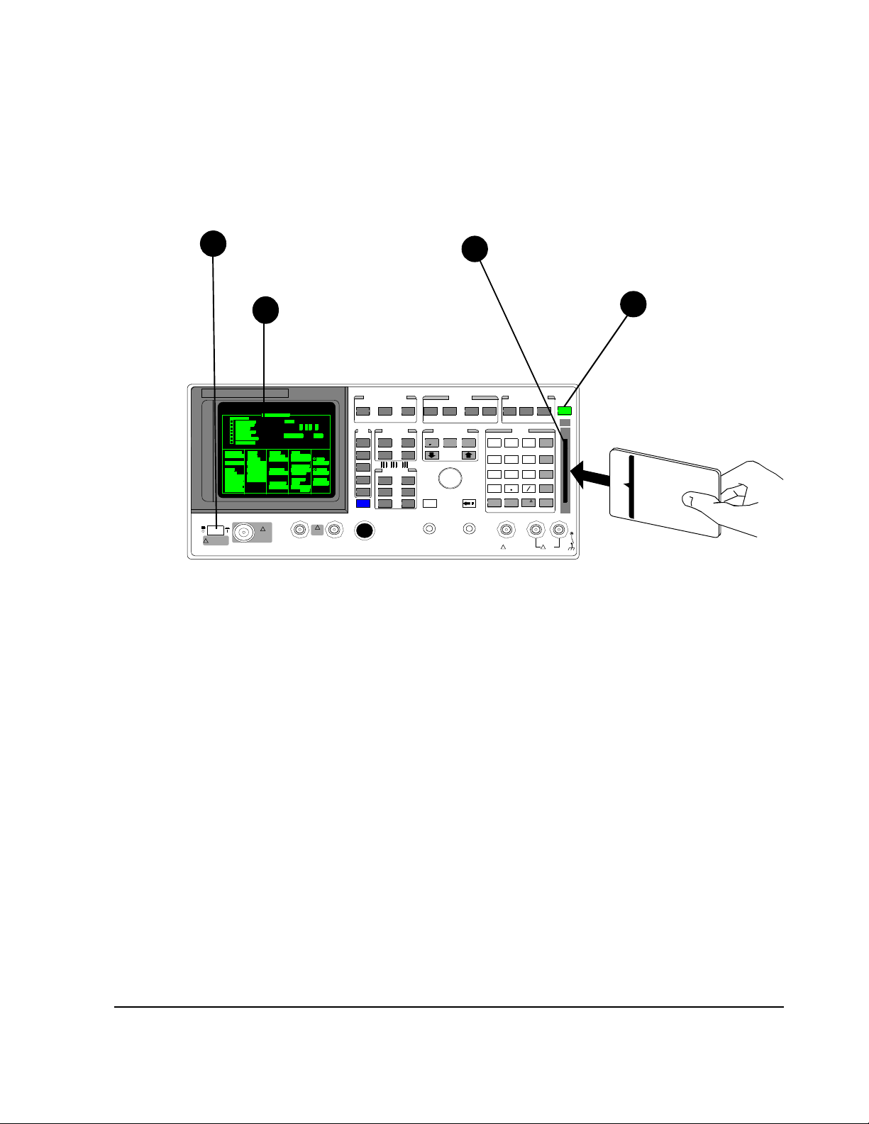
Figure 21 Turning power on and inserting the memory card.
Press
d
PRESET.
Preset returns the Test Set
to the RX Test screen.
61

Chapter 2, Installation
Load and Run the Connectivity Test Software (Option 001 or 002)
Press TESTS to display the
1
TESTS (Main Menu) screen.
If you are in the IBASIC TESTs
screen, press PRESET before
pressing TESTS.
Position cursor at Card and select it.
3 4
Position cursor at Select Procedure Location:
2
and select it.
Position cursor at Select Procedure Filename:
and select it.
Position cursor at Choices: and
select
SYS_CONN.
Figure 22 Loading and Running the Connectivity Test
62
Position cursor at Run Test and select it.
65
The software is now loading.
Loading Time:
First time:
approximately
1.5 minutes.
After first time:
approximately
10 seconds.

Chapter 2, Installation
Load and Run the Connectivity Test Software (Option 001 or 002)
Notes about GPIB
connections
Connectivity Test
guidelines
Disconnect other GPIB devices, especially system controllers, from the Test
System before running the connectivity test. The Test Set is the system controller
when the connectivity test is running and another (external) controller on the bus
will generate a bus conflict error.
The following general guidelines may be useful to you when running the
connectivity test.
Presentation of results on the Test Set’s display
The software uses the following conventions when displaying information on the
Test Set’s display:
Top display line: the very first line of text at the top of the Test Set display is used to
indicate the test being performed.
Two-line inverse text area: just below the top display line is a two-line inverse video
area that is used to prompt the user with instructions.
Main display area: below the inverse area is the main display area of the Test Set. This
large area is used to display test results and to present error messages that may occur.
Softkey (USER key) label area: at the upper right of the Test Set’s display are five
inverse video labels that are used to indicate the function of the corresponding softkey
(k1 to k5). These keys are used to run the software, continue it at key points, and for
other assorted functions.
Pauses during connectivity test execution
As the testing is done to verify connectivity, the software will display abbreviated
results on the main screen of the Test Set’s display. If the program pauses and
gives a prompt before the testing is complete, it is typically to communicate that it
has found a problem. In this case the program will suggest cable paths (and
cables) to check before going on with the testing.
63

Chapter 2, Installation
Where to go next
Where to go next
If you have run the
connectivity
software with a pass
result
If you encountered
failures when
running the
connectivity
software
Now that the Test System’s operation has been verified, you will want to start
making tests on radio equipment.
• If you are planning to test CDMA subscriber units using the Agilent 8924C with the
serial port control, refer to the Agilent 8924C User’s Guide.
• If you are planning to test TDMA subscriber units using the Agilent 8920B with the
serial port control, refer to the Agilent 8920B User’s Guide.
• If you are planning to test CDMA base stations using the Agilent 8921A, refer to the
CDMA/PCS Base Station Test Software User’s Guide.
• If you are planning to test radio equipment using the Agilent 8920A,B, Agilent 8921A,
or Agilent 8924C with the GPIB interface control, refer to the Manual Control Soft-
ware User’s Guide for the next steps in making tests using the manual control software.
If it finds problems, the connectivity software will prompt you to check various
connections in the Test System. The software will then repeat the testing to verify
that the problem has been corrected.
If failures persist after running the Test System connectivity software, you may
have a failure in one of the pieces of test equipment in the Test System. The
connectivity software will attempt to identify the failed unit. Once the suspected
failed unit is identified, contact your nearest Agilent Technologies Service Center
for instructions on servicing the unit.
In North America you may call, toll-free, 1-800-827-3848 (between 9 am and
5 pm, Pacific time) for instructions on further troubleshooting and how to proceed
if repairs are needed. Refer to the last page of this manual for service center
addresses and locations.
64

3P
rogramming the PCS Interface using GPIB
Control
What’s included in this chapter:
• Introduction
• Overview of programming issues
• PCS Interface programming guide
65
Programming the
PCS Interface

Chapter 3, Programming the PCS Interface using GPIB Control
Introduction
Introduction
The PCS Interface extends the frequency range of the Test Set to the 1710 to
1785 MHz, 1805 to 1910 MHz, and 1930 to 1990 MHz PCS band. Since the PCS
Interface has no front-panel user controls, its only available control interface is
through GPIB.
NOTE: To control the PCS Interface over GPIB, some form of control software must be used. The
software can run on either an external controller or in the Test Set’s IBASIC controller. No
“manual” front panel controls of the PCS Interface are provided.
The information in this chapter does not apply when an Agilent 8924C is controlling the
PCS Interface over the serial port.
Purpose This chapter is designed to assist Software Application Designers who will be
integrating the PCS Interface into their own testing system and who as a result,
will need to develop their own software. It provides task flow diagrams,
programming examples, and recommends a testing theory to help guide the
development of control software.
When integrating the PCS Interface into a custom test system, there are a few
topics which must be considered. The following discussions provide general
overviews of these topics. The remaining sections of this chapter then provide
more specific procedures for making the various settings and measurements with
the PCS Interface.
66

Chapter 3, Programming the PCS Interface using GPIB Control
Overview of Programming Issues
Overview of Programming Issues
Features The basic features of the PCS Interface include:
• A PCS frequency RF generator for receiver testing
• A PCS frequency signal analyzer for transmitter testing
• A power detector for direct power measurements
• A temperature sensor for accuracy compensations
The PCS Interface takes the signal generated by the Test Set (810 to 995 MHz) at
its FROM DUPLEX OUT port and upconverts it to a PCS frequency band
(1710 to 1785 MHz, 1805 to 1910 MHz, or 1930 to 1990 MHz) signal at the unitunder-test (UUT) port.
Conversely, the PCS Interface takes the UUT’s transmitted signal (1710 to
1785 MHz, 1805 to 1910 MHz, or 1910 to 1990 MHz), downconverts it to a
frequency the Test Set is capable of analyzing (650 to 940 MHz), and applies it to
the Test Set’s ANT IN port. Both the PCS Interface’s generator and analyzer
paths include variable attenuators for controlling signal levels in the Test System.
The power detector inside the PCS Interface provides direct measurements of the
UUT’s transmitter power.
In order to provide the best possible accuracy and confidence in measurements,
the PCS Interface has built-in temperature sensing circuitry which is used to
determine whether re-calibration is needed. Three compensations are available for
re-calibration and will be discussed in detail later in this chapter.
67

Chapter 3, Programming the PCS Interface using GPIB Control
Overview of Programming Issues
System
Connections
NOTE: It is assumed that all connections between the Test Set and Cellular Adapter have been
made. Refer to the User’s Guide for your Cellular Adapter for instructions on connecting
it to the Test Set.
For connections between the Test Set and PCS Interface, refer to chapter 2,
"Installation".
UUT Port Selection The PCS Interface has two ports available for UUT connection; the RF IN/OUT
port and the RF OUT only port. Use the PCS Interface’s RF IN/OUT port for
single-port devices (for example, a subscriber unit) or its RF OUT only port for
devices with separate RX and TX ports (for example, a base station).
Frequency Setting The PCS Interface provides a PCS frequency generator by upconverting the Test
Set’s generator signal with a stepped local oscillator (LO) and mixer. It downconverts a PCS frequency transmitter signal for analysis by the Test Set using a
fixed frequency LO and mixer. For convenience, conversion bypass paths are also
provided which eliminate any connection changes when testing devices in the 800
to 960 MHz band.
68

Agilent 83236B
Chapter 3, Programming the PCS Interface using GPIB Control
Overview of Programming Issues
EXT TRIG IN
(Frame C lk from
Agilent 8320NX)
ADC CPU GPIB
GPIB (to Agilent 892NX)
Serial (to Agilent 8924C)
DET OUT (to Agilent 8924C)
REF IN (from Agilent 892NX)
REF OUT
To ANT IN
650 to 940 MHz
(to Agilent 892NX)
FROM DUPLEX OUT
810 to 995 MHz
(from Agilent 892NX)
RF IN/OUT
1710 to 1990 MHz
(to UUT)
RF OUT only
1710 to 1990 MHz
(to UUT)
Serial
TEMP Sense
1050 or 1060 MHz
SW1
1
0
1
0
SW2
Pwr Det
TX ATTEN
0 to 40 dB
1 dB step
RX ATTEN
0 to 70 dB
10 dB step
790, or 990 MHz to 1110 MHz
10 MHz step
REF
Figure 23 PCS Interface block diagram
NOTE: The frequency conversion tables, used internally by the PCS Interface’s CPU to determine
the Test Set’s frequencies, are shown in Appendix A, Frequency Conversion Tables on
page 137.
The frequencies desired at the UUT’s ports are set using GPIB commands. When
the PCS Interface receives the generator or analyzer frequency settings over
GPIB, its CPU automatically controls the conversion/bypass and internal LO
settings in its generator and analyzer paths. In addition, the PCS Interface’s CPU
determines the frequencies required for the Test Set’s RF generator and analyzer.
These values are returned over GPIB and are then used by the controlling
software to set the Test Set’s generator and analyzer frequencies.
69

Chapter 3, Programming the PCS Interface using GPIB Control
Overview of Programming Issues
Generator level
Setting
The PCS Interface’s generator path has a 0 to 70 dB attenuator with 10 dB steps
which provide coarse level settings of the RF generator. Fine level control is
provided by the 0.1 dB resolution of the Test Set’s DUPLEX OUT port.
The output signal level desired at the UUT’s port is set using an GPIB command.
When the PCS Interface’s generator level setting is received over GPIB, the CPU
of the PCS Interface automatically determines the appropriate generator path
attenuator setting, and computes a level which should be set at the Test Set’s
DUPLEX OUT port. This level is returned over GPIB and is then used by the
controlling software to set the Test Set’s RF generator level.
The automatic attenuator and level computations performed by the PCS
Interface’s CPU include two factors which are stored internally; a temperature (of
the PCS Interface) factor and an attenuation step accuracy factor. The temperature
correction factor is updated during the generator level temperature compensation
which is discussed later. The attenuator step accuracy correction factor is
established as part of the factory calibration. Both factors are also a function of
the current generator frequency. Therefore, the generator level setting should be
done after setting the desired RF generator frequency.
70

Chapter 3, Programming the PCS Interface using GPIB Control
Overview of Programming Issues
Analyzer
Attenuator Setting
The PCS Interface’s analyzer path has a 0 to 40 dB attenuator with 1 dB steps.
This attenuator is adjusted to optimize the signal level through the PCS
Interface’s downconverter to the Test Set’s ANT IN port.
After the UUT’s transmitter signal is applied to the PCS Interface’s RF IN/OUT
port, the setting of the analyzer path attenuator can be automatically set using an
GPIB command. When the command is received, the PCS Interface uses the
internal peak detector to measure the peak power at its RF IN/OUT port, then
computes and sets the analyzer path attenuator accordingly.
NOTE: This is a one-time setting and does not place the PCS Interface in an auto-ranging mode. If
the TX signal level changes, the attenuation setting command should be sent again.
The automatic computation performed by the PCS Interface’s CPU to set the
attenuator uses a factor stored in the PCS Interface; the attenuation step accuracy
factor. The attenuator step accuracy correction factor is established as part of the
factory calibration. This factor is also a function of the current analyzer
frequency, therefore the automatic attenuator setting should be done after the
UUT’s transmitter frequency is set in the PCS Interface and after the UUT’s
transmitter signal is applied to the RF IN/OUT port.
NOTE: The analyzer path attenuator can also be set to a specified value over GPIB.
71

Chapter 3, Programming the PCS Interface using GPIB Control
Overview of Programming Issues
Power Detector,
Triggering Types,
and Power
Measurements
The power detector
The PCS Interface has a built-in detector for direct power measurements of the
UUT’s transmitter signals connected to the RF IN/OUT port.
Triggering types
Trigger and data collection features have been included to provide direct power
measurements of continuous wave (CW), TDMA, and continuous CDMA
signals. Three triggering types are available.
• Immediate trigger
• Internal amplitude trigger
• External trigger
Detailed procedures for setting trigger types and data collection conditions are
discussed later in this chapter.
Power measurements
After the UUT’s transmitter signal is applied to the RF IN/OUT port and the
desired trigger and data collection conditions are set in the PCS Interface, the
power measurement is performed using an GPIB query. When the query
command is received, the PCS Interface’s CPU collects power measurement
samples from the internal detector, selects the appropriate data, calculates the
resulting power, then returns the result over GPIB.
The power calculation performed by the PCS Interface’s CPU includes two
correction factors, frequency drift and dc drift correction factors which are
established during factory calibration. To assure that the correct factors are
applied, the desired UUT transmitter frequency should be set in the PCS Interface
and the dc offset compensation should be performed before making the power
measurement.
72

Chapter 3, Programming the PCS Interface using GPIB Control
Overview of Programming Issues
Temperature
Compensations
Power measurement accuracy and signal level accuracy in the PCS Interface are
affected by temperature. The PCS Interface has an internal temperature sensor
which is used during compensations which are necessary to ensure that the
accuracy specified is achieved. Temperature compensations, which use a
temperature sensor in the PCS Interface, are used to re-calibrate the PCS Interface
when the temperature variations exceed an acceptable value. Default temperature
changes are 1°C. This default value is required to maintain the performance
specifications shown in chapter 5, "Specifications".
The two compensations
1. DC offset temperature compensation
This compensation procedure removes the dc drift of the power detector to provide
accurate power measurements of signal levels less than 0 dBm. During this procedure
the UUT connected to the PCS Interface’s RF IN/OUT port is disconnected from the
analyzer path so the zero power condition can be measured. This process updates the
dc drift compensation factor used in power measurements.
Before making a transmitter power measurement, the dc offset temperature
compensation should be performed using a single GPIB command.
Since the UUT is internally disconnected from the Test Set during dc offset
compensation, it should be performed before an active traffic/voice channel link is
established if over-the-air protocol is used. Otherwise, the active call may be dropped.
NOTE: Over-the-air protocol - The Test Set can essentially simulate a cellular base station and
use over-the-air protocol to establish and maintain an active voice/traffic channel. This
protocol can be used with a subscriber unit UUT connected to the Test System.
73

Chapter 3, Programming the PCS Interface using GPIB Control
Overview of Programming Issues
2. Generator level temperature compensation
This compensation is necessary to maintain the generator’s output level accuracy
which is used for testing receivers. During this procedure the UUT is automatically
internally disconnected from the generator and analyzer path. The PCS Interface’s
internal compensation factors are used to compute the generator path attenuator values
and the required signal level from the Test Set’s DUPLEX OUT port.
Before using the generator for receiver testing, the need for a new generator level
temperature compensation should be checked. The controlling software queries the
PCS Interface to determine if a temperature compensation is necessary. If the
compensation is necessary, it is performed by the controlling software with a few
GPIB commands.
Since the UUT is internally disconnected from the Test Set during generator level
compensation, it should be performed before an active traffic/voice channel link is
established if over-the-air protocol is used. Otherwise, the active call may be dropped.
NOTE: Turn on desired modulation before the generator level temperature compensation for best
accuracy.
74

Chapter 3, Programming the PCS Interface using GPIB Control
PCS Interface Programming Guide
PCS Interface Programming Guide
For a complete description of the PCS Interface GPIB commands used in this
chapter see chapter 4, "GPIB Commands".
Conventions Used Examples given in this chapter will include: the instrument to be programmed, the
command string, and the reference page in this manual for the given command
string.
For example:
To the PCS Interface> COMP:TEMP:REQ:RES (page 104)
or
To the Test Set> RFAN:INP ‘Ant’
NOTE: Reference information (reference page) for the command strings used to program the Test
Set are not included in this manual. Refer to your Test Set’s programming guide for
complete descriptions.
75

Chapter 3, Programming the PCS Interface using GPIB Control
Test Procedure Flow
Test Procedure Flow
Figure 24 is an overview of the initialization, set up, and measurement steps
required in control software when using a PCS Interface in a test system.
Start
Figure 24
Initialize the
System
Set Up and
Measure
More?
N
End
Place the Test Set and PCS Interface into known
instrument states.
Set up the Test Set for use with the PCS Interface.
Set up and make each of the desired
measurements.
Y
76

Initialize the System
Figure 25 shows the tasks necessary to initialize the Test System.
Chapter 3, Programming the PCS Interface using GPIB Control
Initialize the System
Test Procedure Flow
Start
Initialize the System
Reset the System
Initialize the
System
Initialize the PCS Interface
Temperature Compensation
Set Up and
Measure
Y
More?
N
End
Set Up the Test Set’s
Ports and Tune Mode
Figure 25
Reset the System The PCS Interface and the Test Set need to be reset to their default instrument
settings.
1. Use the following command string to reset the Test Set and query for completion.
To the Test Set> *RST;*OPC?
2. Use the following command string to reset the PCS Interface and query for completion.
To the PCS Interface> *RST;*OPC? (page 99)
77

Chapter 3, Programming the PCS Interface using GPIB Control
Initialize the System
Set Up the
Test Set’s Ports and
Tune Mode
When The Test Set was reset in the previous step, its RF IN/OUT port was
designated by default. The PCS Interface requires connections to the Test Set’s
DUPLEX OUT and ANT IN ports.
Placing the Test Set in Manual Tune mode will provide accurate frequency error
results when transmitter frequency measurements are made.
1. Use the following command string to set the Test Set’s RF analyzer port to ANT IN.
To the Test Set> RFAN:INP ‘Ant’
2. Use the following command string to set the Test Set’s RF generator port to
DUPLEX OUT.
To the Test Set> RFG:OUTP ‘Dupl’
3. Use the following command string to set the Test Set’s tune mode to Manual.
To the Test Set> RFAN:TMOD ‘Manual’
78

Set Up and Measure
Figure 26 shows the tasks necessary to set up and measure with the Test System.
Test Procedure Flow
Chapter 3, Programming the PCS Interface using GPIB Control
Set Up and Measure
Set Up and Measure
Start
Initialize the
System
Set Up and
Measure
More?
N
End
Set the Test Frequencies
Y
and Levels (for RX or TX testing)
Perform the Temperature
Initialize
Set Up the UUT
Ports
Compensations
Figure 26
Activate the
UUT
Set the TX Attenuator
Level (for TX testing)
Set up the Power Detector
(for TX power measurements)
Make the Measurement
79

Chapter 3, Programming the PCS Interface using GPIB Control
Set Up and Measure
Initialize 1. Use the following command string to initialize the PCS Interface and query for
completion.
To PCS Interface> SYST:PRES; *OPC? (page 113)
NOTE: The SYST:PRES command string will reset the PCS Interface but will maintain the current
temperature compensation. Do not use the *RST command during this initialization since
it will reset the temperature compensation. Compensations will be done at the first time
requested following the *RST command.
Set Up the UUT
ports
NOTE: When the RF:PATH command is executed, the TX and RX attenuators are automatically
The internal signal path switches of the PCS Interface can be controlled to route
the Test Set’s connections to or from the UUT.
1. Use the following command string for RX testing at the PCS Interface’s RF OUT only
port and for TX testing at the PCS Interface’s RF IN/OUT port.
To the PCS Interface> RF:PATH 1 (page 107)
2. Use the following command string for both RX and TX testing at the PCS Interface’s
RF IN/OUT port.
To the PCS Interface> RF:PATH 2 (page 107)
set to their maximum values of 40 dB and 70 dB, respectively.
80

Chapter 3, Programming the PCS Interface using GPIB Control
Set Up and Measure
Set the Test
Frequencies and
Levels (for RX or
TX testing)
Set the generator frequency for receiver testing
The PCS Interface takes the source signal from the Test Set’s DUPLEX OUT port
and routes the signal to the UUT port RF OUT only (or RF IN/OUT). Based on
the frequency requested at the UUT port, the PCS Interface automatically
determines if the upconversion or bypass path is used.
1. Use the following command string to indicate the desired testing frequency at the UUT
port and to query the PCS Interface for the corresponding frequency needed at the its
FROM DUPLEX OUT port.
To the PCS Interface> RX:TSET:FREQ? <desired frequency>
(page 111)
2. Define a local constant for the frequency obtained in step 1.
For example: Duplex_freq
3. Use the following command string to set the Test Set’s DUPLEX OUT frequency.
To the Test Set> RFG:FREQ <Duplex_freq>
NOTE: Table 14 on page 138 describes the frequency conversions automatically made by the PCS
Interface.
Set the generator level for receiver testing
The PCS Interface is designed to optimize the level accuracy of the generator’s
output. It automatically computes the optimum signal level to set the Test Set’s
DUPLEX OUT port to in order to obtain the desired signal level at the PCS
Interface’s UUT port.
NOTE: Refer to the specifications for the output levels available from both the RF OUT only and
RF IN/OUT ports.
1. Use the following command string to indicate the signal level desired at the PCS
Interface’s UUT port and to query the PCS Interface for the corresponding signal level
needed at its FROM DUPLEX OUT port.
To the PCS Interface> RX:TSET:LEV? <desired level>
(page 112)
2. Define a local constant for the signal level obtained in step 1.
For example: Duplex_lev
3. Use the following command string to set the Test Set’s DUPLEX OUT level.
To the Test Set> RFG:AMPL <Duplex_lev>
81

Chapter 3, Programming the PCS Interface using GPIB Control
Set Up and Measure
NOTE: Since the level required at the PCS Interface’s FROM DUPLEX OUT port is computed as
a function of frequency, the generator level should be set after the generator frequency is
set.
Set the analyzer frequency for transmitter testing
The PCS Interface takes the transmitter output signals from the UUT connected to
its RF IN/OUT port and routes the signal to the Test Set’s ANT IN port. Based on
the frequency requested at the PCS Interface’s UUT port, the PCS Interface
automatically determines if the downconversion path or bypass path is used.
1. Use the following command string to set the PCS Interface’s down-converter for the
expected transmitter frequency at the PCS Interface’s UUT port and to query the PCS
Interface for the corresponding frequency to be expected at the Test Set’s ANT IN port.
To the PCS Interface> TX:TSET:FREQ? <test frequency>
(page 120)
2. Define a local constant for the frequency obtained in step 1.
For example: Ant_freq
3. Use the following command string to tune the Test Set’s RF analyzer frequency to the
UUT’s transmitter frequency.
To the Test Set> RFAN:FREQ <Ant_freq>
NOTE: Table 14 on page 138 in the attached appendix describes the conversions for frequency
automatically made by the PCS Interface.
Set the analyzer attenuation level if you are establishing an active link between the
Test Set and the UUT using over-the-air protocol.
1. If an active link using over-the-air protocol is going to be established between the Test
Set and the UUT, the attenuator may need to be set to a minimum value. This will allow
the Test Set to receive the UUT’s transmitted signal at a high enough level to establish
the link.
Use the following command string to set the attenuator of the PCS Interface’s
analyzer path to 0 dB.
To the PCS Interface> TX:OUTP:ATT 0 dB (page 118)
82

Chapter 3, Programming the PCS Interface using GPIB Control
Set Up and Measure
Perform the
Temperature
Compensations
Two temperature compensations are available. The dc offset compensation is
required to achieve the most accurate transmitter power measurements. The
generator level compensation provides the best generator level accuracy for
receiver testing. See "Temperature Compensations" on page 73 for a more
detailed description of these two compensations.
Temperature compensation for transmitter testing.
If the power detector in the PCS Interface is to be used for making a transmitter
power measurement, both the dc offset temperature compensation and the power
detector compensation should be checked and performed if necessary.
1. Use the following command to perform the dc offset temperature compensation.
To PCS Interface> COMP:PDET:DCOF:EXEC (page 100)
Temperature compensation for receiver testing
Since the Test System’s source is used for receiver testing, the generator level
temperature compensation should be checked and performed, if necessary, prior
to making a receiver measurement.
1. Check and see if the generator level temperature compensation is necessary.
a. Use the following command to query the PCS Interface for whether generator level
compensation is necessary.
To PCS Interface> COMP:TEMP:REQ:STAT? (page 105)
b. Store the result as a local constant.
For example: Status
2. If compensation is necessary (for example, Status=1), then set up the Test System for
the temperature compensation.
a. Use the following command string to indicate the frequency band desired for
receiver testing and to query the PCS Interface for the resulting frequency needed
at its FROM DUPLEX OUT port.
To the PCS Interface> COMP:TEMP:FREQ? <band or frequency>
(page 102)
b. Define a local constant for the Test Set’s DUPLEX OUT frequency obtained in
step a.
For example: Duplex_freq
c. Use the following command string to set the Test Set’s generator frequency.
To the Test Set> RFG:FREQ <Duplex_freq>
83

Chapter 3, Programming the PCS Interface using GPIB Control
Set Up and Measure
d. Use the following command string to query the PCS Interface for the signal level
required at its FROM DUPLEX OUT port.
To the PCS Interface> COMP:TEMP:LEV? (page 103)
e. Define a local constant for the level obtained in step d.
For example: Duplex_lev
f. Use the following command string to set the Test Set’s generator level.
To the Test Set> RFG:AMPL <Duplex_lev>
3. Use the following command string to perform the generator level temperature
compensation.
To the PCS Interface> COMP:TEMP:EXEC? (page 101)
84

Chapter 3, Programming the PCS Interface using GPIB Control
Set Up and Measure
Activate the
Activate the RX and/or TX functions of the UUT.
UUT
NOTE: You need to determine the steps required here. You can either control the UUT with the
Test Set’s call processing capabilities or some other means of direct control.
Set the TX
Attenuator Level
(for TX testing)
NOTE: Do not have a signal generator level greater than −50 dBm at the RF IN/OUT port when
NOTE: This is a one time setting and does not place the PCS Interface in an auto-ranging mode. If
The PCS Interface is designed to optimize the level of the signal passed to the
Test Set’s RF analyzer. With a single GPIB command, the PCS Interface will
automatically adjust its analyzer path attenuation. This should be performed after
the active signal is connected to the RF IN/OUT port.
1. Use the following command string to set the PCS Interface’s analyzer path attenuation
to obtain the optimum signal level into the Test Set’s ANT IN port and to query for
completion.
To the PCS Interface> TX:OUTP:LEV:ADJ; *OPC? (page 119)
adjusting the attenuator level. This may require that you reduce the level of the signal
generator.
the TX signal level changes, the attenuation setting command should be sent again.
The optimum level out of the PCS Interface’s TO ANT IN port can be modified using the
TX:OUTP:LEV command, and the TX:OUTP:RFAN:PATH:IL? command can return
the path loss from the RF IN/OUT port to the TO ANT IN port
be used to develop custom attenuator setting procedures in the controlling software which
can be used if a known signal level will be connected to the RF IN/OUT port.
Since the attenuator setting is a function of frequency, the analyzer’s attenuator should be
adjusted after the analyzer’s frequency is set.
85
. These two commands can

Chapter 3, Programming the PCS Interface using GPIB Control
Set Up and Measure
Set Up the Power
Detector
(for TX power
measurements)
NOTE: The subscriber unit UUT must be in an active link with the Test Set when using the frame
Before making a power measurement, the triggering type and data collection
conditions must be set and the
TX:INP:FREQ must be set so the correct
compensation factors are applied to the measurement. See table 9 on page 88 for
application examples of triggering types and data collection.
1. Select the trigger type
• Immediate trigger - Measurements are started when the instrument is ready after
being instructed to make a power measurement. This type should be used for any
continuous signal measurement.
• Amplitude trigger - Measurements start when the PCS Interface detects that the
positive edge of the pulsed signal crosses the trigger threshold. This trigger mode
is useful for signal levels above −5 dBm (0.316 mW).
• External trigger - The frame clock output from the TDMA Cellular Adapter
provides external trigger control.
clock for external triggering.
Use the following command string to select the trigger type.
To the PCS Interface> TX:INP:POW:TRIG <trigger type>
(page 118)
86

Chapter 3, Programming the PCS Interface using GPIB Control
Set Up and Measure
2. Select the data collection conditions
In addition to the trigger features, a subset of the collected data can be selected for use
in power computations using IGNORE, LENGTH, and AVERAGE values.
NOTE: The IGNORE value is valid only for the Internal amplitude trigger or the External trigger.
Trigger Event
(for External Trigger)
Trigger
Threshold
(for Amplitude
Trigger)
IGNORE
a. Use the following command string to define the number of measurement samples
b. Use the following command string to define the number of samples to collect
c. Use the following command string to define the number of bursts (ranging from 1
LENGTH
(ranging from 3 to 3200) (12.5 µs/sample) to ignore after the trigger conditions
have been satisfied.
To the PCS Interface> TX:INP:POW:PDET:SAMP:IGN <desired number> (page 117)
(ranging from 1 to 4800) in the measurement after trigger conditions and IGNORE
samples have been satisfied.
To the PCS Interface> TX:INP:POW:PDET:SAMP:LENG <desired number> (page 117)
to 10) to include in the power measurement. IGNORE and LENGTH conditions
will be applied to each burst.
To the PCS Interface> TX:INP:POW:PDET:SAMP:AVER <desired number> (page 116)
AVERAGE
87

Chapter 3, Programming the PCS Interface using GPIB Control
Set Up and Measure
NOTE: If the Immediate trigger is used, up to 48000 samples can be collected by the combination
of the LENGTH and AVERAGE values.
Table 9 Example power measurement set ups for typical applications
TX:INP:POW:PDET:SAMP TX:INP:POW:TRIG
:AVER
(AVERAGE
TRIGGERING
)
1 IMM (Immediate)
1
1
EXT (External)
AMPTD (Amplitude)
TYPE
CDMA
Base Station
CDMA
Subscriber Unit
TDMA
Base Station
TDMA
Application
Subscriber Unit
TDMA
Subscriber Unit
:IGN
(IGNORE)
:LENG
(LENGTH)
— 4800 4 IMM (Immediate)
— 4800 4 IMM (Immediate)
—
See footnote
See
2
2
footnote
3
17 461 See footnote
1
461 See footnote
(Signals > −5 dBm)
1. The total number of points used in the power measurement determines the accuracy achieved.
The measurement accuracy is:
180
----------
± 5%
[] This applies @ 23 ± 10 degrees C±
µW
N
180
± 10%
----------
[] This applies @ 0 to 55 degrees C±
µW
N
Where:
N = total number of points used, or LENGTH*AVERAGE from the table above
2. The PCS Interface’s power detector sample rate is 80 kHz. For the US TDMA symbol rate of
24.3 kHz, this implies 3.29 samples/symbol. The values for IGNORE and LENGTH provide
power measurements compliant with the IS-137 specification of at least 140 symbols between
symbols 6 and 162 in the burst.
88

Chapter 3, Programming the PCS Interface using GPIB Control
Set Up and Measure
3. Since the frame trigger signal from the Cellular Adapter is used for the external trigger, and the
subscriber unit is locked to the Test System’s frame clock, transmitter power measurements can
be made on any of the 6 TDMA slots by adjusting the IGNORE value.
IGNORE = (S*533) + 2001, for S = slot number = 1, 2
IGNORE = (S*533) − 1197, for S = slot number = 3, 4, 5, 6
89

Chapter 3, Programming the PCS Interface using GPIB Control
Set Up and Measure
Make the
Measurement
NOTE: The power detector temperature compensation is automatically performed when the
NOTE: Since the Test Set does not automatically correct for the frequency and amplitude changes
Transmitter power for using the PCS Interface is available in addition to other
measurements from the Test Set.
• Transmitter Power measurements
Use the following command string to query the power measurement from the
PCS Interface.
To the PCS Interface> TX:INP:POW? (page 115)
TX:INP:POW? command string is used to make a power measurement.
When performing the power measurement, the RF generator level should be set to less than
−50 dBm if the RF IN/OUT port is used, or set to less than −30 dBm if the RF OUT only
port is used.
• Other Test Set measurements
Refer to the Test Set’s programming guide for making other measurements.
due to the conversions in the PCS Interface, absolute frequency (using the Auto Tune
mode) and absolute amplitude measurements will not be accurate. For example:
Absolute TX frequency = (1050 or 1060 MHz conversion) + Test Set’s frequency reading
90

4G
PIB Commands
What’s included in this chapter:
• Introduction
• The Syntax of Program Messages
• Reference Information for each GPIB command
• GPIB Command Summary
91
GPIB Commands

Chapter 4, GPIB Commands
Introduction
Introduction
The PCS Interface is controlled only by GPIB commands from the Test Set’s
internal IBASIC controller or the user-supplied external controller.
The GPIB commands for the PCS Interface comprise common commands and
subsystem commands.
NOTE: The information in this chapter does not apply when an Agilent 8924C is controlling the
PCS Interface over the serial port.
Common Commands
An asterisk (*) is always placed in front of a common command. These common
commands conform to IEEE 488.2.
Subsystem Commands
Subsystem commands are hierarchies composed of multiple commands
connected by colons. The hierarchies are also called “command trees.”
Subsystem Command Trees
The command at the base of a subsystem command tree is called the root
command, or simply the root. (This is similar to the terminology used for the
directory path of DOS files.) To indicate the command at the beginning of the
tree, the path from the root must be specified. Immediately after the power is
turned on or a preset is carried out, the root is specified as the current path. The
following method can be used to change this path’s specification.
Program Message Terminator A program message terminator such as
<new line> returns the current path to the root.
Colon (:) Inserting a colon between two commands causes the current
path to branch one level down. If a colon is placed in front of a
command it indicates that the command is the root command.
Semicolon (;) A semicolon indicates the separation of two groups of com-
mands. A semicolon does not change the specification of the
current path.
An example of how colons and semicolons are used within a command tree is
shown in figure 27 on page 93.
92

Chapter 4, GPIB Commands
Introduction
Common commands such as *RST may not be used in a subsystem. Common
commands function regardless of the current specified path.
Returns the current path to root.
R
Causes the current path to branch one level down.
D
Does not change the specification of the current path.
N
Figure 27 The Correct Use of Colons and Semicolons
Command Abbreviations
Abbreviations can be used for some commands. This manual does not use
abbreviations for commands when describing them. However, the letters that are
used in the abbreviation of the command appear in uppercase, and the letters that
must be omitted to form the abbreviation appear in lowercase.
For example, this manual indicates that the abbreviation of the command
:SYSTEM is :SYST by showing it as :SYSTem. (Abbreviations such as :SYSTE
are not valid.)
93

Chapter 4, GPIB Commands
The Syntax of Program Messages
The Syntax of Program Messages
This section details the format and parameters of program messages.
Program messages are sent by the computer to the measuring device. They are
comprise one or more commands, the symbols that separate each command, and a
message termination symbol (terminator).
Uppercase and Lowercase Letters
No distinction is made between uppercase and lowercase letters in program
messages.
Program Message Terminator
The program message terminators are <newline>, <^END>, and
<newline><^END>. <^END> is used to indicate the end of a program message.
<^END> means that an EOI (End Of Identify) was transmitted, signaling that data
transmission through an GPIB interface has been completed.
For example, the
to the end of data transmissions. For IBM PC computers, the specification for the
terminator that is transmitted can be changed by changing the environment
settings of the system.
Multi-messages
More than one command can be included in a message. When this is done a
semicolon is used to separate the commands.
*RST;*IDN?
HP BASIC OUTPUT statement automatically adds an <^END>
94

The Syntax of Query Messages and Response Messages
Commands other than those described in the command reference as “No Query”
can be used as Query commands. To send a Query command as a message, add a
? to the end of the character string as shown in the example below.
*IDN?
Commas and semicolons are used to separate data in response messages. Commas
are used to separate multiple return values in response to a Query command.
Semicolons are used to separate the responses to multiple Query commands
transmitted as one message. As an example, the response to the message
:QUERY1?;QUERY2? is shown below.
<data1>,<data1>;<data2>,<data2>
<newline><^END> is transmitted at the end of the message to indicate the end of
the message.
Chapter 4, GPIB Commands
The Syntax of Program Messages
95

Chapter 4, GPIB Commands
The Syntax of Program Messages
Parameters
One <space> has to be inserted between the command character string of the
subsystem and the first parameter.
When more than one parameter has to be added to a command, commas are used
to separate the parameters.
Types of Parameters
Command parameters have many formats. Previously defined fixed formats that
correspond to each command are used in the replies. The formats that may be
used for each command are noted in the command reference.
• The use of one of the following numeric formats is indicated by <numeric>.
no decimal point
100
100.
with decimal point
, +235 with a minus or plus sign
−1.23
4.56eëû
3 exponential expression with a space after the e
−7.89E−01
.5
only to the right of the decimal point
exponential expression with an E or an e
There is a limit to the numeric formats that can be used when using a program to
specify the settings of the PCS Interface. A “rounding-off” operation is automatically
carried out if a specified parameter exceeds this limit. <numeric> data that is in
response to a Query command is always in an <NR1> (integer) or an <NR3> (decimal
point) format.
• Suffixes
When a suffix has to be used with a command, multiplier suffixes (such as K for kilo)
and unit suffixes can be used. (If a multiplier suffix is used, it must be accompanied by
a unit suffix, such as HZ.)
Frequency: HZ (Hz; default setting), KHZ (kHz), MAHZ or MHZ (MHz),
GHZ (GHz)
Power: DBM (dBm; default setting), W (W)
Temperature: DEG (°C; default setting)
Suffixes may be omitted. If they are, the default suffixes will be used.
96

Chapter 4, GPIB Commands
The Syntax of Program Messages
Conventions The following conventions and definitions are used in this chapter to describe
GPIB operation.
Þ RX[:RFG1]:TSET:LEVel? ëû <numeric>[DBM]
(1)
(2) Þ Returns the level required at the FROM DUPLEX OUT port, when
the level of the wanted signal at the RF IN/OUT or RF OUT only is
specified in
Þ <numeric>: −130 to −10 dBm for RF:PATH 1
(3)
Þ •Response to the Query
(4)
{numeric (dBm)} <new line><^END>
<numeric>. (Query only)
−130 to −20 dBm for RF:PATH 2
(1) Command name and required parameter.
When a parameter is required, there must be a space between it and a code.
(ëû indicates a space.)
When several items are enclosed by {} brackets, only one of the elements
may be selected. For example, {OFF|ON|0|1} means OFF, ON, 0, or 1. Characters enclosed in the [] brackets are optional and may be omitted.
(2) Description
(3) Parameter description
(4) Query response
97

Chapter 4, GPIB Commands
Common Commands
Common Commands
*IDN?
Returns the ID of the PCS Interface. (Query only)
• Response to the Query
HEWLETT-PACKARD,HP83236B,xxxxxxxxxx,REV.yy.yy <newline><^END>
where, xxxxxxxxxx is a serial number and yy.yy is a firmware version.
*OPT?
Returns the options that are installed. (Query only)
NO OPTION:
The frequency range is limited. See "Change 1" on page
145 for details.
WIDE BAND: All of the frequency range documented in this manual can
be used.
• Response to the Query
{NO OPTION|WIDE BAND} <newline><^END>
98

*RST
Returns all of the settings of the PCS Interface to their default settings. (No
Query)
Table 10 SYST:PRES Command Settings
Command Setting
COMP:PDET:DCOF:REQ:RES 1
COMP:PDET:TEMP:REQ:RES 1
COMP:TEMP:REQ:RES 1
RF:PATH 0
RX:OUTP:ATT 70 dB
RX:OUTP:FREQ 1930 MHz
RX:OUTP:LEV −130 dBm
TX:INP:FREQ 1850 MHz
TX:INP:POW:PDET:SAMP:AVER 1 (for the Immediate Trigger)
Chapter 4, GPIB Commands
Common Commands
5 (for the Amplitude or External Trigger)
TX:INP:POW:PDET:SAMP:IGN
TX:INP:POW:PDET:SAMP:LENG 4800 (for the Immediate Trigger)
TX:INP:POW:TRIG IMM
TX:INP:POW:UNIT dBm
TX:OUTP:ATT 40 dB
TX:OUTP:LEV −9 dBm
17
461 (for the Amplitude or External
Trigger)
99

Chapter 4, GPIB Commands
COMPensation Subsystem
COMPensation Subsystem
COMPensation:PDET:DCOFfset:EXECute
This command measures the dc offset values of the power detector. The dc offset
value is used to calculate the measurement value from the actual output value of
the power detector. This is the equivalent of zeroing the power meter.
NOTE: The dc offset values are also updated at power-up of the PCS Interface or after executing
the *RST command or the COMP:TEMP:EXEC? command.
The query form of this command is used to measure the current temperature value
and compare it to the value stored the last time dc offset values were measured.
When the difference is greater than or equal to the value set by the
COMP:PDET:DCOF:REQ:RES command, the PCS Interface stores the current
value, and returns 1 (TRUE). If the difference is less than the value set by the
COMP:PDET:DCOF:REQ:RES command, the PCS Interface does nothing and
only returns 0 (FALSE).
• Response to the Query
{0|1} <new line><^END>
0: The PCS Interface did nothing, because the temperature change is
less than the value defined by the COMP:PDET:DCOF:REQ:RES
command.
1: The PCS Interface measures the dc offset of the power detector and
stores the measured values into the non-volatile memory, because the
temperature change is larger than the value defined by the
COMP:PDET:DCOF:REQ:RES command.
100
 Loading...