


Agilent Technologies Microwave
System Amplifiers
83006A 10 MHz to 26.5 GHz
83017A 500 MHz to 26.5 GHz
83018A 2 to 26.5 GHz
83020A 2 to 26.5 GHz
83050A 2 to 50 GHz
83051A 45 MHz to 50 GHz
Features
• Ultra broadband to 50 GHz
• Up to 1 watt output power
• Compact size
Agilent Frequency Gain Pout
Model (GHz) (dB)
(dBm)
83006A 0.01–26.5 20 13
83017A 0.5–26.5 25 18
83018A 2–26.5 27 24
83020A 2–26.5 30 30
83050A 2–50 21 18
83051A 0.045–50 23 12*
* 10 dbm 45–50 GHz
The Agilent microwave system amplifiers are compact, off-the-shelf amplifiers designed for systems designers
and integrators. This family of amplifiers provides power where you need
it to recover system losses and to
boost available power in RF and microwave ATE systems.
The ultrabroad bandwidth from 10 MHz
to 50 GHz allows the designer to
replace several narrow bandwidth
amplifiers with a single Agilent amplifier, eliminating the need for crossover
networks or multiple bias supplies.
The 83050A power amplifier and
83051A preamplifier expand frequency
performance to 50 GHz, while the
1 Watt 83020A offers broadband
power to 26 GHz. The small amplifier
footprint allows for simple in-line
insertion to existing system blocks
that require amplification. The standard 83017A, 83018A, and 83020A
include internal directional detectors
for external leveling applications.
The 83020A is optionally available
without the coupler-detector providing up to +30 dBm and +25 dBm,
respectively. With excellent noise figure relative to their broad bandwidth
and high gain, these amps significantly improve system noise figure and
dynamic range. These products come
equipped with a low profile heat sink,
an integral mounting bracket, and a
two-meter DC power supply cable.
Thermal and power supply design
allows fast, easy integration into most
measurement systems.
Agilent 83000A Series
Microwave System Amplifiers
Product Overview

2
Applications
Small envelope size makes the Agilent
Technologies family of microwave
system amplifiers ideal for automated
test and benchtop applications, offering the f lexibility to place power
where you need it.
Boost Source Output Power
Increase output power from
microwave sources to increase test
system dynamic range. Drive high
input power devices such as TWTs,
mixers, power amps, or optical modulators. Drive test devices into compression for device characterization.
Recover Systematic Losses
The microwave system amplifiers
help solve the power loss from connectors, cables, switches, and signal
routing components which consume
valuable source power. Long transmission paths, common in antenna
applications, are particularly susceptible to such losses.
Level Source Power
By using feedback to an external
source ALC input, system designers
can level output power at the test
port, negating the effects of postsweeper reflections and losses.
Simply route the directional detector
output to the source external ALC
input connector. The figures at right
show typical results.
The 83020A, 83018A, and 83017A feature an integral directional detector
to supply feedback. To level an 83006A
amplifier, use the 0.01 to 26.5 GHz
83036C directional detector or the
1 to 26.5 GHz 87300C coupler with
an 8474C detector.
8360 Synthesized Sweeper
REMOTE LEVELING
1 dB/Div
0.5 26.5
Amplifier Output
Unleveled Output
Leveled Output
Frequency (GHz)
Microwave System Amplifier
83017A
83020A
Unleveled Output
1 dB/div
Leveled Output
1 26.5
Frequency (GHz)
(2.6 GHz per division)
1 dB/div
83017A
Remote
Test Bench
83018A
Unleveled Output
1 dB/div
Leveled Output
1 26.5
Unleveled Output
Frequency (GHz)
(2.6 GHz per division)
Leveled Output
0.5 26.5
Frequency (GHz)
(2.6 GHz per division)

3
Improve Measurements
The 83006A, 83017A, and 83051A
preamplifiers increase the sensitivity
and dynamic range of spectrum
analyzers. Add a preamplifier to
noise figure measurement systems
to significantly lower system noise
figure. The table below shows typical
system noise figure reduction achievable with these amplifiers. Note that
the reduced system noise figure is
dominated by the preamplifier noise
figure. See Application Note 57-2,
literature number 5952-3706.
Benchtop Gain Block
Benchtop microwave design tasks
often require amplification to measure low level output characteristics,
improve system dynamic range,
perform saturation tests, or boost
power levels. The Agilent family of
system amplifiers offers small size
and immediate, off-the-shelf solutions
to microwave design, production,
or test engineers.
Pulse Parameter Measurements
Fast rise time and multi-octave
bandwidth make these amplifiers
attractive for fast pulse parameter
measurements. The 0.01, 0.5, and
2 GHz cutoff frequencies make them
more useful for RF or impulse measurements with low duration times.
F
sys
–1
F
new
= Fpa+
G
pa
All terms linear
Amp Freq Max Min System Noise Figure (F
sys
) without preamp (dB)
Model (GHz) NF(dB) Gain(dB) 13 15 18 20 23 25 30
83006A 0.01–0.2 13 20 13.1 13.1 13.2 13.4 13.6 14.8
0.2–18 8 8.1 8.2 8.4 8.6 9.2 9.8 12.1
18–26.5 13 13.1 13.1 13.2 13.4 13.6 14.8
83017A 0.5–18 8 25 8.0 8.1 8.1 8.2 8.4 8.6 9.8
18–26.5 13 13.0 13.0 13.1 13.1 13.2 13.6
83018A 1–2 10 23 10.0 10.1 10.1 10.2 10.4 10.6 11.8
2–20 10 27 10.0 10.0 10.1 10.1 10.2 10.3 10.8
20–26.5 13 23 13.0 13.1 13.1 13.2 13.3 14.0
83020A 1–20 10 30 10.0 10.0 10.0 10.0 10.1 10.1 10.4
20–26.5 13 27 13.0 13.1 13.1 13.1 13.1 13.4
85050A 2–26.5 6 21 6.1 6.2 6.3 6.5 7.0 7.5 9.5
26.5–50 10 10.0 10.1 10.1 10.2 10.4 10.6 11.8
83051A 0.045–2 12 23 12.0 12.0 12.1 12.1 12.3 12.4 13.2
2–26.5 6 6.1 6.2 6.3 6.5 7.0 7.5 9.5
26.5–50 10 10.0 10.1 10.1 10.2 10.4 10.6 11.8
Typical Noise Figure Improvement
SENSITIVITY IMPROVEMENT
70211C
Spectrum Analyzer
8360
Source
CAL
DUT
83006A
–120
–130
–140
–150
–160
–170
DANL (dBm)
–180
–190
0.15 10152026
DANL (min) 10 Hz RBW
Before
After
Frequency (GHz)

4
Product Specifications
Model Number 83006A 83017A 83018A
Frequency Range 10 MHz–26.5 GHz 0.5–26.5 GHz 2–26.5 GHz
Small Signal Gain 20 dB min 25 dB min 23 dB typ 1–2 GHz
27 dB min 2–20 GHz
23 dB min 20–26.5 GHz
Small Signal ±5 dB max 0.01–5 GHz ±5 dB max 0.5–2 GHz ±5 dB typ
Gain Flatness ±3 dB max 5–26.5 GHz ±5 dB max 2–26.5 GHz
Output Power +18 dBm typ 0.01–10 GHz +20 dBm typ 0.5–20 GHz +23 dBm typ 1–2 GHz
2
(At P max) +16 dBm typ 10–20 GHz +15 dBm typ 20–26.5 GHz +24 dBm min 2–20 GHz
2,3
+14 dBm typ 20–26.5 GHz +21 dBm min 20–26.5 GHz
2,3
(At 1 dB compression) +13 dBm min 0.01–20 GHz +18 dBm min 0.5–20 GHz +22 dBm typ 1–2 GHz
+10 dBm min 20–26.5 GHz +18 dBm–0.75 dB/GHz +22 dBm min 2–20 GHz
(20<f<26.5 GHz) +17 dBm min 20–26.5 GHz
Leveled Output Power N/A ±1.1 dB 0.5–26.5 GHz at 12 dBm ±1.5 dB 1–26.5 GHz at 17 dBm
Flatness
1
±1.5 dB 0.5–20 GHz at 18 dBm
Noise Figure <13 dB typ 0.01–0.1 GHz <8 dB typ 0.5–20 GHz <10 dB typ 1–20 GHz
<8 dB typ 0.1–18 GHz <13 dB typ 20–26.5 GHz <13 dB typ 20–26.5 GHz
<13 dB typ 18–26.5 GHz
Harmonics –25 dBc 0.01–11 GHz –20 dBc 0.5–11 GHz –22 dBc typ 1–2 GHz
(At spec’d value of P1 dBC) –25 dBc typ 11–13.25 GHz –20 dBc typ 11–13.25 GHz –19 dBc 2–11 GHz
–19 dBc typ 11–13.25 GHz
Harmonics N/A N/A –20 dBc typ 1–2 GHz
(At spec’d max power) –17 dBc typ 2–11 GHz
–17 dBc typ 11–13.25 GHz
Input SWR 2.6:1 2.6:1 3:1 typ 1–2 GHz
3:1 2–26.5 GHz
Output SWR 2.8:1 0.01–18 GHz 2.6:1 7.0:1 typ 1–2 GHz
3.2:1 18–26.5 GHz 4.5:1 2–10 GHz
2.2:1 10–26.5 GHz
Non-Harmonically –65 dBc typ –65 dBc typ –65 dBc typ
Related Spurious
Rise Time 400 ps typ 310 ps typ 275 ps typ
Third Order Intercept (TOI) 30 dBm typ at 2 GHz 30 dBm typ at 2 GHz 36 dBm typ 2–20 GHz
20 dBm typ at 26.5 GHz 20 dBm typ at 26.5 GHz 31 dBm typ 20–26.5 GHz
Impedance 50Ω typ 50Ω typ 50Ω typ
Reverse Isolation (typ) –65 dB –65 dB –55 dB at 1 GHz
+0.95 dB/GHz
Survival Input Power +23 dBm max +23 dBm max +23 dBm max
Power Dissipation 6 W 9 W 24 W
1. At min specified P1 dBC within given frequency band
2. P max measured with 0 dBm input
3. Option 001 Pmax +25 dBm 2–20 GHz, +22 dBm 20–26.5 GHz

5
Product Specifications (continued)
Model Number 83020A 83050A 83051A
Frequency Range 2–26.5 GHz 2–50 GHz 45 MHz–50 GHz
Small Signal Gain 30 dB typ 1–2 GHz 21 dB min 23 dB min
30 dB min 2–20 GHz
27 dB min 20–26.5 GHz
Small Signal ±5 dB typ ±3.5 dB max ±3.5 dB max
Gain Flatness
Output Power +30 dBm typ 1–2 GHz
2
+20 dBm 2–40 GHz +12 dBm to 45 GHz
(At P max) +30 dBm min 2–20 GHz
2,3
+19 dBm–0.2 dB/GHz +10 dBm 45–50 GHz
+30 dBm –0.7 dB/GHz
2,3
(40<f<50 GHz)
(20<f<26.5 GHz)
(At 1 dB compression) +28 dBm typ 1–2 GHz +15 dBm 2–40 GHz +8 dBm 45 MHz–45 GHz
+28 dBm min 2–20 GHz +13 dBm 40–50 GHz +6 dBm 45–50 GHz
+28 dBm–0.7 dB/GHz
(20<f<26.5 GHz)
Leveled Output Power ±1.5 dB typ 1–26.5 GHz N/A N/A
Flatness
1
At 23 dBm
Noise Figure <10 dB typ 1–20 GHz <6 dB typ 2–26.5 GHz <12 dB typ 45 MHz–2 GHz
<13 dB typ 20–26.5 GHz <10 dB typ 26.5–50 GHz <6 dB typ 2–26.5 GHz
<10 dB typ 26.5–50 GHz
Harmonics –22 dBc typ 1–2 GHz –20 dBc typ 2–18 GHz –20 dBc typ 45 MHz–18 GHz
(At Spec’d value of P1 dBC) –20 dBc typ 2–11 GHz –18 dBc typ 18–25 GHz –18 dBc typ 18–25 GHz
–17 dBc typ 11–13.25 GHz
Harmonics –20 dBc typ 1–2 GHz N/A N/A
(At Spec’d max power) –17 dBc typ 2–11 GHz
–17 dBc typ 11–13.25 GHz
Input SWR 3:1 typ 1–26.5 GHz 2.1 max 2.1 max
Output SWR 7.0:1 typ 1–2 GHz 2.8 max 2–18 GHz 2.2 max
4.5:1 2–10 GHz 2.1 max 18–50 GHz
2.2:1 10–26.5 GHz
Non-Harmonically –65 dBc typ –50 dBc typ –50 dBc typ
Related Spurious
Rise Time 375 ps typ 250 ps typ 225 ps typ
Third Order Intercept (TOI) 38 dBm typ 2–20 GHz 27 dBm typ 27 dBm typ
33 dBm typ 20–26.5 GHz
Impedance 50Ω typ 50Ω typ 50Ω typ
Reverse Isolation (typ) –55 dB –50 dB typ –50 dB typ
Survival Input Power +23 dBm max +20 dBm max +20 dBm max
Power Dissipation 48 W 11 W 5 W
1. At min specified P1 dBC within given frequency band
2. P max measured with +5 dBm input
3. Option 001 deletes detected output, for Pmax add 0.5 dBm 1–26.5 GHz
Special Applications: Higher performance models available upon request
(i.e., higher power, etc.)

6
General Specifications
Model Number 83006A 83017A 83018A
*Bias Voltage and Current 12 ±1 Vdc at 450 mA 12 ±1 Vdc at 700 mA 12 ±1 Vdc at 2A
(nominal) –12 ±1 Vdc at 50 mA –12 ±1 Vdc at 50 mA –12 ±1 Vdc at 50
mA
RF Connectors 3.5 mm (f) 3.5 mm (f) 3.5 mm (f)
Detector Output N/A BNC (f) BNC (f)
Detector Sensitivity N/A 15µV/µW 4µV/µW
Detector Polarity N/A Negative Negative
Weight: net 0.64 kg (1.4 lb) 0.64 kg (1.4 lb) 1.8 kg (4.0 lb)
shipping 1.32 kg (2.9 lb) 1.32 kg (2.9 lb) 2.9 kg (6.4 lb)
*Do not apply positive voltage before negative voltage.
Environmental Specifications
Temperature Coefficient –0.07 dB/° C –0.1 dB/° C –0.13 dB/° C
of Gain
Operating Temperature 0 to +55° C 0 to +55° C 0 to +55° C
Storage Temperature –40 to +70° C –40 to +70° C –40 to +70° C
Other Environmental Information
EMC
1
IEC 61326:1997/EN 61326:1997
CISPR 11:1997/EN 55011:1998, Group 1, Class A
Safety IEC 348:1978/HD 401 S1:1981
CAN/CSA-C22.2 No. 231 (Series M-89)
Moisture Resistance 65° C at 95% RH for 10 days per Mil-Std-883C method 1004.5
Random Vibration 5.2 G (rms) to 2000 Hz per Mil-Std-883C method 2026 test condition 11A
Shock 1500 G (peak), 0.5 ms per Mil-Std-883C method 2002.3 test condition B
Altitude, non-operating 15,000 m per Mil-Std-883C method 1001 test condition C
1. This ISM device complies with Canadian ICES-001. Cet appareil ISM est conforme a la norme NMB-001 du Canada.

7
General Specifications (continued)
Model Number 83020A 83050A 83051A
*Bias Voltage and Current 15 ±1.5 Vdc at 3.2A 12 ±1 Vdc at 830 mA 12 ±1 Vdc at 425 mA
(nominal) –15 ±0.5 Vdc at 40 mA –12 ±1 Vdc at 50 mA –12 ±1 Vdc at 50 mA
RF Connectors 3.5 mm (f) 2.4 mm (f) 2.4 mm (f)
Detector Output BNC (f) N/A N/A
Detector Sensitivity 1 µV/µW N/A N/A
Detector Polarity Negative N/A N/A
Weight: net 3.9 kg (8.5 lb) 0.64 kg (1.4 lb) 0.64 kg (1.4 lb)
shipping 5.0 kg (11 lb) 1.32 kg (2.9 lb) 1.32 kg (2.9 lb)
*Do not apply positive voltage before negative voltage.
Environmental Specifications
Temperature Coefficient –0.19 dB/° C –0.09 dB/° C –0.09 dB/° C
of Gain
Operating Temperature 0 to +55° C 0 to +55° C 0 to +55° C
Storage Temperature –40 to +70° C –40 to +70° C –40 to +70° C
Other Environmental Information
EMC:
1
IEC 61326:1997/EN 61326:1997
CISPR 11:1997/EN 55011:1998, Group 1, Class A
Safety: IEC 348:1978/HD 401 S1:1981
CAN/CSA-C22.2 No. 231 (Series M-89)
Moisture Resistance 65° C at 95% RH for 10 days per Mil-Std-883C method 1004.5
Random Vibration 5.2 G (rms) to 2000 Hz per Mil-Std-883C method 2026 test condition 11A
Shock 1500 G (peak), 0.5 ms per Mil-Std-883C method 2002.3 test condition B
Altitude, non-operating 15,000 m per Mil-Std-883C method 1001 test condition C
1. This ISM device complies with Canadian ICES-001. Cet appareil ISM est conforme a la norme NMB -001 du Canada.
Specifications: describe the instrument’s warranted performance over the temperature range +20° C to +30° C (unless otherwise noted). All specifications apply after the
instrument’s temperature has been stabilized after one hour continuous operation. Typical characteristics are intended to provide information useful in applying the instrument
by giving typical but nonwarranted performance parameters. These are denoted as “typical” or “nominal” and apply over the temperature range +20° C to +30° C.
Caution on Electrostatic Discharge: Electrostatic discharge (ESD) can damage or destroy electronic components. It is recommended that these amplifiers, like other electronic
components, be installed and operated at a static-free workstation or in an environment where precautions against ESD have been implemented.

8
Graphical Performance Data
83006A Amplifier 83017A Amplifier 83018A Amplifier
Power at 1 dB Compression Point (dBm)
24
20
16
12
8
0.01 5 10 15 20 26.5
Gain (dB)
35
30
25
20
15
10
5
0.01 5 10 15 20 26.5
Harmonics (dBc) at rated P1 dBc
0
–10
–20
–30
–40
–50
–60
–70
–80
0.01 5 10 15 20 26.5
Frequency (GHz)
Frequency (GHz)
Frequency (GHz)
Power at 1 dB Compression Point (dBm)
24
20
16
12
8
0.5 5 10 15 20 26.5
Gain (dB)
45
40
35
30
25
20
15
0.5 5 10 15 20 26.5
Harmonics (dBc) at rated P1 dBc
0
–10
–20
–30
–40
–50
–60
–70
–80
0.5 5 10 15 20 26.5
Frequency (GHz)
Frequency (GHz)
Fundamental Frequency (GHz)
Maximum Output Power (dBm)
32
30
28
26
24
22
20
1 5 10 15 20 26.5
Gain (dB)
40
38
36
34
32
30
28
26
24
22
20
1 5 10 15 20 26.5
Power at 1 dB Compression Point (dBm)
32
30
28
26
24
22
20
18
16
1 5 10 15 20 26.5
Frequency (GHz)
Frequency (GHz)
Frequency (GHz)
Noise Figure (dB)
18
16
14
12
10
8
6
4
2
0.01 5 10 15 20 26.5
Frequency (GHz)
Noise Figure (dB)
18
16
14
12
10
8
6
4
2
0.5 5 10 15 20 26.5
Frequency (GHz)
Noise Figure (dB)
20
18
16
14
12
10
8
6
4
2
0
1 5 10 15 20 26.5
2nd Harmonic (dBc) at Pout = 22 dBm
0
–5
–10
–15
–20
–25
–30
–35
–40
–45
–50
1 5 10 15 20 26.5
Frequency (GHz)
Fundamental Frequency (GHz)

9
Graphical Performance Data (continued)
83020A Amplifier 83050A Amplifier 83051A Amplifier
Maximum Output Power (dBm)
36
34
32
30
28
26
24
0 5 10 15 20 26.5
Gain (dB)
45
41
37
33
29
25
21
0 5 10 15 20 26.5
Power at 1 dB Compression Point (dBm)
36
34
32
30
28
26
24
22
20
0 5 10 15 20 26.5
Frequency (GHz)
Frequency (GHz)
Frequency (GHz)
Maximum Output Power (dBm)
25
24
23
22
21
20
19
18
17
01020304050
Gain (dB)
34
32
30
28
26
24
22
20
010203040 50
Power at 1 dB Compression Point (dBm)
26
24
22
20
18
16
14
12
10
01020304050
Frequency (GHz)
Frequency (GHz)
Frequency (GHz)
Maximum Output Power (dBm)
22
20
18
16
14
12
10
8
6
0 1020304050
Gain (dB)
40
38
36
34
32
30
28
26
24
22
20
01020304050
Power at 1 dB Compression Point (dBm)
18
16
14
12
10
8
6
4
2
01020304050
Frequency (GHz)
Frequency (GHz)
Frequency (GHz)
Noise Figure (dB)
14
13
12
11
10
9
8
7
6
5
4
0 5 10 15 20 26.5
2nd Harmonic (dBc) at Pout = 27 dBm
0
–5
–10
–15
–20
–25
–30
–35
–40
–45
–50
0 5 10 15 20 26.5
Frequency (GHz)
Fundamental Frequency (GHz)
Noise Figure (dB)
14
12
10
8
6
4
01020304050
2nd Harmonic (dBc) at Pout = 17 dBm
10
15
20
25
30
35
40
01020304050
Frequency (GHz)
Fundamental Frequency (GHz)
Noise Figure (dB)
14
12
10
8
6
4
01020304050
2nd Harmonic (dBc) at Pout = 9 dBm
10
15
20
25
30
35
40
01020304050
Frequency (GHz)
Fundamental Frequency (GHz)
10
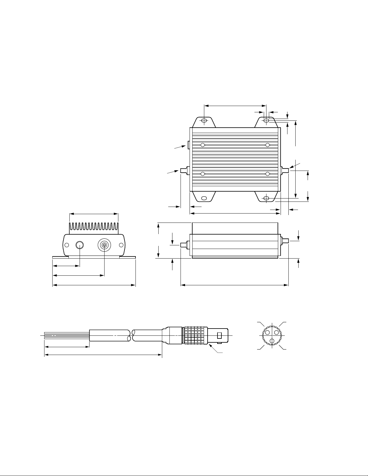
Amplifier Outline Drawings
1
83006-60004 dc bias cable. Cable shipped with 8300A, 83017A, 83018A, 83050A, and 83051A.
83006A
1. Dimensions in millimeters and (inches).
33.8
(1.33)
DC Bias
63.1
(2.49)
Tol = ±0.2 (0.008)
61.0
(2.40)
102.5
(4.04)
RF
In
DC Bias
RF In
12.7
(0.50)
45.2
(1.78)
16.5
(0.65)
76.2
(3.00)
111.0
(4.37)
132.0
(5.20)
6.1
(0.24)
4.6
(0.18)
88.9
(3.50)
RF Out
38.9
(1.53)
8.3
(0.32)
21.5
(0.85)
White/Brown/Grey
25.0
(1.0)
2 m
(79.0)
Red
Dot
Ground
Grey
+12V
White/Yellow/Grey
–12V
Red
Dot

11
Amplifier Outline Drawings (continued)
83017A
83018A
36.9
(1.45)
61.0
(2.40)
DC Bias
102.5
(4.04)
RF
In
23.6
(0.93)
DC Bias
RF In
8.7
(0.34)
(1.78)
45.2
76.2
(3.00)
111.0
(4.37)
131.7
(5.19)
6.1
(0.24)
4.6
(0.18)
Tol = ±0.2 (0.008)
88.9
(3.50)
Detector Out
RF Out
12.0
(0.47)
21.5
(0.85)
42.1
(1.65)
16.5
(0.65)
RF
Out
Det Out
36.9
(1.45)
65.7
(2.58)
DC Bias
37.8
(1.49)43(1.69)
RF
In
76.2
(3.0)
DC
Bias
RF
75.9
(3.0)
202
(7.95)
In
4.6
(0.18)
208.7
(8.2)
211.9
(8.3)
Tol = ±0.2 (0.008)
Detector Out
RF Out
6.1
(0.24)
114.3
(4.5)
RF Out
40
(1.57)
Det
Out
35.3
(1.39)

12
Amplifier Outline Drawings (continued)
83020A
83050A and 83051A
RF Out
Detector Out
95.3
(3.8)
Pin No. 1
15
57.0
(2.2)
RF In
45.2
(1.8)
9
274.0
(10.8)
254.0
(10.0)
166.0
(6.5)
DC
Bias
6.5
(0.26)
1
8
Note: 18 gauge wire minimum
2 m
(79)
12.0
(0.47)
83020-60004
202.0
(8.0 )
27.9
(1.1)
20.0
(0.8)
34.4
(1.4)
RF In
33.3
(1.3)
Tol = ±0.2 (0.008)
RF Out
DC Bias
25.0
(1.0)
Detector
Out
Yellow Pin 7 –15V
Black Pin 5 Ground
Green Pin 3 +15V
21.0
(0.8)
85.5
(3.4)
36.9
(1.45)
DC Bias
61.0
(2.40)
102.5
(4.04)
RF
In
39.3
(1.55)
DC Bias
RF In
8.7
(0.34)
(1.78)
45.2
76.2
(3.00)
(4.37)
111.0
131.7
(5.19)
6.1
(0.24)
4.6
(0.18)
Tol = ±0.2 (0.008)
88.9
(3.50)
RF Out
21.5
(0.85)
42.1
(1.65)
RF
Out
16.5
(0.65)

13
Power Supply Outline Drawings
87421A
87422A
The 87421A power supply provides the dc power needed to bias the 83006A, 83017A, 83018A, 83050A, and 83051A.
The 87422A power supply provides the dc power needed to bias the 8302A, plus an additional ±12V dc output.
57.2
‰
(2.25)
‰
‰
14.5 (0.57)
‰
‰
‰
(2.50)
63.5
5.0
(0.197)
‰
DC
Output
‰
57.2
(2.25)
‰
‰
‰
25.4
‰
‰
‰
(1.00)
‰
Fuse
‰
114.3
(4.50)
‰
Pin No. 1
AC
Input
‰
83006-60005
2 m
(79)
‰
Pin No. 1
‰
Tol = ±0.2 (0.008)
‰
‰
175.8
163.1
(6.92)
148.6
(6.42)
(5.85)
‰
‰
‰
274.0
(10.9)
254.0
(10.0)
87422A
POWER SUPPLY
–
Output A ±12V
85.5
(3.4)
R typ
(.13)
(.47)
Pin No. 1
9
15
Pin No. 1
6
9
3.3
12.0
166.0
(6.5)
202.0
(8.0)
6.5
(0.26)
1
Top Panel
21.8
(.86)
87422-60001
On/Off
Output B ±15V
OUTPUT A
+12 VDC 2.0 A
–12 VDC 200 mA
OUTPUT B
+15 VDC 4.0 A
–15 VDC 200 mA
8
2 m
(79)
‰
1
83006-60005
5
2 m
(79)
Front Panel
INPUT
90-250 VAC ~ 47-63 Hz
T 2.5 A TIME DELAY
250 V
Rear Panel

14
Ordering Information
Agilent 83006A, 83017A, 83050A, and
83051A microwave system amplifiers
Includes amplifier and part number
83006-60004, which is a two-meter
cable with a three-pin connector on
one end and three-wire leads on the
other end.
Agilent 83018A microwave system
amplifier
Includes amplifier and part number
83006-60004, which is a two-meter
cable with a three-pin connector on
one end and three-wire leads on the
other end.
• Special Applications: Higher
performance models available
upon request.
Agilent 83020A microwave system
power amplifier
Includes amplifier and part number
83020-60004, which is a two-meter
cable with a fifteen-pin connector on
one end and three-wire leads on the
other end.
• Option 001: Delete coupler/detector
providing higher output power.
• Special Applications: Higher
performance models available
upon request.
Other Instruments
and Accessories
Agilent 83036C coaxial GaAs
directional detector
0.01–26.5 GHz, for use with the
83006A.
Agilent 87421A power supply
Includes power supply and part
number 83006-60005, which is a twometer cable with a three-pin connector
on one end and a D-sub-miniature
connector on the other end for direct
connection to the 83006A, 83017A,
83018A, 83050A, and 83051A.
Agilent 87422A power supply
Includes power supply and part
number 83020-60001, which is a
two-meter cable with fifteen-pin
connectors for direct connection to
the 83020A amplifier. One additional
cable, part number 83006-60005, is
provided for direct connection of
the 12V dc output to a preamplifier
such as the 83006A, 83017A,
83018A, 83050A, or 83051A.
Related Literature
Agilent 83036C
data sheet, 5952-1874
Agilent 87421A/87422A
data sheet,5091-4292E

Agilent Technologies’ Test and Measurement Support,
Services, and Assistance
Agilent Technologies aims to maximize the value you
receive, while minimizing your risk and problems. We
strive to ensure that you get the test and measurement
capabilities you paid for and obtain the support you
need. Our extensive support resources and services can
help you choose the right Agilent products for your
applications and apply them successfully. Every instrument and system we sell has a global warranty. Support
is available for at least five years beyond the production
life of the product. Two concepts underlie Agilent’s overall support policy: “Our Promise” and “Your Advantage.”
Our Promise
Our Promise means your Agilent test and measurement
equipment will meet its advertised performance
and functionality. When you are choosing new equipment, we will help you with product information, including realistic performance specifications and practical
recommendations from experienced test engineers.
When you use Agilent equipment, we can verify that it
works properly, help with product operation, and provide
basic measurement assistance for the use of specified
capabilities, at no extra cost upon request. Many selfhelp tools are available.
Your Advantage
Your Advantage means that Agilent offers a wide range
of additional expert test and measurement services,
which you can purchase according to your unique technical and business needs. Solve problems efficiently and
gain a competitive edge by contracting with us for calibration, extra-cost upgrades, out-of-warranty repairs,
and onsite education and training, as well as design,
system integration, project management, and other professional engineering services. Experienced Agilent
engineers and technicians worldwide can help you maximize your productivity, optimize the return on investment
of your Agilent instruments and systems, and obtain
dependable measurement accuracy for the life of those
products.
Agilent T&M Software and Connectivity
Agilent’s Test and Measurement software and connectivity products, solutions and developer network allows
you to take time out of connecting your instruments to
your computer with tools based on PC standards, so you
can focus on your tasks, not on your connections. Visit
www.agilent.com/find/connectivity
for more information.
By internet, phone, or fax, get assistance with all your
test & measurement needs
Phone or Fax
Product specifications and descriptions in this document
subject to change without notice.
© Agilent Technologies, Inc. 2002
Printed in USA, October 14, 2002
5963-5110E
www.agilent.com/find/emailupdates
Get the latest information on the
products and applications you select.
United States:
(tel) 800 452 4844
Canada:
(tel) 877 894 4414
(fax) 905 282 6495
China:
(tel) 800 810 0189
(fax) 800 820 2816
Europe:
(tel) (31 20) 547 2323
(fax) (31 20) 547 2390
Japan:
(tel) (81) 426 56 7832
(fax) (81) 426 56 7840
Korea:
(tel) (82 2) 2004 5004
(fax) (82 2) 2004 5115
Latin America:
(tel) (305) 269 7500
(fax) (305) 269 7599
Taiwan:
(tel) 0800 047 866
(fax) 0800 286 331
Other Asia Pacific
Countries:
(tel) (65) 6375 8100
(fax) (65) 6836 0252
Email:
tm_asia@agilent.com
 Loading...