


User's Guide
HP 8169A Polarization Controller
SERIAL NUMBERS
This guide applies to all instruments.
ABCDE
HP Part No. 08169-91011
Printed in the Federal Republic of Germany
First Edition
E0396

Notices
This document contains proprietary
information that is protected by
copyright. All rights are reserved.
No part of this document may be
photocopied, reproduced, or
translated to another language
without the prior written consent of
Hewlett-Packard GmbH.
c
Copyright 1993 by:
Hewlett-Packard GmbH
Herrenberger Str. 130
71034 Boeblingen
Federal Republic of Germany
Subject Matter
The information in this document is
subject to change without notice.
Hewlett-Packard makes no warranty
of any kind with regard to this
printed material, including, but not
limited to, the implied warranties of
merchantability and tness for a
particular purpose.
Hewlett-Packard shall not be liable
for errors contained herein or for
incidental or consequential damages
in connection with the furnishing,
performance, or use of this material.
Printing History
New editions are complete revisions
of the guide reecting alterations in
the functionality of the instrument.
Updates are occasionally made to
the guide between editions. The
date on the title page changes when
an updated guide is published. To
nd out the current revision of the
guide, or to purchase an updated
guide, contact your Hewlett-Packard
representative.
Control Serial Number: First Edition
applies directly to all instruments.
Warranty
This Hewlett-Packard instrument
product is warranted against defects
in material and workmanship for a
period of one year from date of
shipment. During the warranty
period, HP will, at its option, either
repair or replace products that prove
to be defective.
For warranty service or repair, this
product must be returned to a service
facility designated by HP. Buyer shall
prepay shipping charges to HP and
HP shall pay shipping charges to
return the product to Buyer.
However, Buyer shall pay all shipping
charges, duties, and taxes for
products returned to HP from
another country.
HP warrants that its software and
rmware designated by HP for use
with an instrument will execute its
programming instructions when
properly installed on that instrument.
HP does not warrant that the
operation of the instrument,
software, or rmware will be
uninterrupted or error free.
Limitation of Warranty
The foregoing warranty shall not
apply to defects resulting from
improper or inadequate maintenance
by Buyer, Buyer-supplied software or
interfacing, unauthorized
modication or misuse, operation
outside of the environmental
specications for the product, or
improper site preparation or
maintenance.
No other warranty is expressed or
implied. Hewlett-Packard specically
disclaims the implied warranties of
Merchantability and Fitness for a
Particular Purpose.
First Edition : 1st September 1994 : 08169-91011 : E0994
: 1st March 1996 : 08169-91011 : E0396
Exclusive Remedies
The remedies provided herein are
Buyer's sole and exclusive remedies.
Hewlett-Packard shall not be liable
for any direct, indirect, special,
incidental, or consequential
damages whether based on contract,
tort, or any other legal theory.
Assistance
Product maintenance agreements
and other customer assistance
agreements are available for
Hewlett-Packard products.For any
assistance contact your nearest
Hewlett-Packard Sales and Service
Oce.
Certication
Hewlett-Packard Company certies
that this product met its published
specications at the time of
shipment from the factory.
Hewlett-Packard further certies
that its calibration measurements
are traceable to the United States
National Institute of Standards and
Technology, NIST (formerly the
United States National Bureau of
Standards, NBS) to the extent
allowed by the Institutes's
calibration facility, and to the
calibration facilities of other
International Standards Organization
members.
ISO 9001 Certication
Produced to ISO 9001 international
quality system standard as part of
our objective of continually
increasing customer satisfaction
through improved process control.


Safety Summary
The following general safety precautions must be observed during all phases
of operation, service, and repair of this instrument. Failure to comply with
these precautions or with specic warnings elsewhere in this manual violates
safety standards of design, manufacture
, and intended use of the instrument.
Hewlett-Packard Company assumes no liability for the customer's failure to
comply with these requirements.
General
This is a Safety Class 1 instrument (provided with terminal for
protective earthing) and has been manufactured and tested according to
international safety standards.
Operation - Before applying power
Comply with the installation section.
Additionally, the following shall be observed:
Do not remove instrument covers when operating.
Before the instrument is switched on, all protective earth terminals
, extension
cords, auto-transformers and devices connected to it should be connected to a
protective earth via a ground socket. Any interruption of the protective earth
grounding will cause a potential shock hazard that could result in serious
personal injury.
Whenever it is likely that the protection has been impaired, the instrument
must be made inoperative and be secured against any unintended operation.
Make sure that only fuses with the required rated current and of the specied
type (normal blow, time delay, etc.) are used for replacement. The use of
repaired fuses and the short-circuiting of fuseholders must be avoided.
Adjustments described in the manual are performed with power supplied to
the instrument while protective covers are removed. Be aware that energy at
many points may, if contacted, result in personal injury.
Any adjustments, maintenance, and repair of the opened instrument under
voltage should be avoided as much as possible, and when unavoidable, should
be carried out only by a skilled person who is aware of the hazard involved.
Do not attempt internal service or adjustment unless another person, capable
of rendering rst aid and resuscitation is present. Do not replace components
with power cable connected.
Do not operate the instrument in the presence of ammable gases or fumes.
Operation of any electrical instrument in such an enviroment constitutes a
denite safety hazard.
Do not install substitute parts or perform any unauthorized modication to
the instrument.
Be aware that capacitors inside the instrument may still be charged even if
the instrument has been disconnected from its source of supply.
iv

Safety Symbols
The apparatus will be marked with this symbol when it is
necessary for the user to refer to the instruction manual in
order to protect the apparatus against damage.
Caution, risk of electric shock.
Frame or chassis terminal.
Protective conductor terminal.
Hazardous laser radiation.
Warning
Caution
The WARNING sign denotes a hazard. It calls attention to
a procedure, practice or the like, which, if not correctly
performed or adhered to, could result in injury or loss of
life. Do not proceed beyond a WARNING sign until the
indicated conditions are fully understood and met.
The CAUTION sign denotes a hazard. It calls attention to
an operating procedure, practice or the like, which, if not
correctly performed or adhered to, could result in damage to
or destruction of part or all of the equipment. Do not proceed
beyond a CAUTION sign until the indicated conditions are fully
understood and met.
v


Contents
1. Getting Started
The Basic Operating Principle ................. 1-1
Using the Polarization Controller for Polarization Analysis ... 1-2
Editing ............................ 1-3
Editing Using the Entry Keys . . . . . . . . . . . . . . . . . 1-3
Editing Using the Modify Keys and Knob ........... 1-3
Resetting Parameters . . . . . . . . . . . . . . . . . . . . . 1-4
2. Setting a State of Polarization
Setting up the Hardware . . . . . . . . . . . . . . . . . . . .
Setting the Position of the Polarizing Filter .......... 2-1
Setting the State of Polarization ................ 2-3
Positioning the/4 and/2 Retarder Plates .......... 2-4
Using the Circle Mode .................... 2-4
Example: Setting the Optimum Transmission SoP .. .... 2-4
Set the Polarizing Filter ................. 2-5
Setting the Worst Case Transmission SoP ........ . 2-6
Setting the Optimum Transmission SoP .. ........ 2-7
3. Scanning the Poincare Sphere
Setting up the Hardware . . . . . . . . . . . . . . . . . . . . 3-1
Setting Up and Executing a Scan ................ 3-1
Example: Measuring the Response to a \Depolarized" Signal .. 3-2
Set the Polarizing Filter ........ ........ .. 3-3
Setting Up the Instruments . . . . . . . . . . . . . . . . . 3-4
Running the Scan .... ........ ..... .... 3-4
Example: Measuring a Polarization Dependent Loss ...... 3-5
Set the Polarizing Filter ........ ........ .. 3-6
Setting Up the Instruments . . . . . . . . . . . . . . . . . 3-7
Running the Scan .... ........ ..... .... 3-7
Analyzing the Results .... ........ ...... . 3-7
2-1
Contents-1

4. Other Front Panel Functions
Setting the HP-IB Address ...... ........ ..... 4-1
Storing or Recalling Instrument Settings . . . . . . . . . . . . . 4-1
Storing a Setting . . . . . . . . . . . . . . . . . . . . . . . 4-1
Recalling a Setting . . . . . . . . . . . . . . . . . . . . . . 4-2
Resetting the Instrument . . . . . . . . . . . . . . . . . . . 4-2
5. Programming the Polarization Controller
HP-IB Interface ........................ 5-1
Setting the HP-IB Address ...... ........ ..... 5-3
Returning the Instrument to Local Control ........... 5-3
How the Polarization Controller Receives and Transmits Messages 5-3
How the Input Queue Works ................. 5-3
Clearing the Input Queue . . . . . . . . . . . . . . . . . . 5-4
The Output Queue . . . . . . . . . . . . . . . . . . . . . . 5-4
The Error Queue . . . . . . . . . . . . . . . . . . . . . . . 5-4
Some Notes about Programming and Syntax Diagram Conventions 5-4
Short Form and Long Form.................. 5-5
Command and Query Syntax ................. 5-5
6. Remote Commands
Command Summary ......................
The Common Commands . . . . . . . . . . . . . . . . . . . .
Common Status Information .. ........ ...... . 6-5
SRQ, The Service Request .... ........ ..... 6-6
*CLS .... ........ ...... ........ .. 6-7
*ESE ............................ 6-7
*ESE? . . . . . . . . . . . . . . . . . . . . . . . . . . . 6-8
*ESR? . . . . . . . . . . . . . . . . . . . . . . . . . . . . 6-8
*IDN? . . . . . . . . . . . . . . . . . . . . . . . . . . . . 6-9
*OPC . . . . . . . . . . . . . . . . . . . . . . . . . . . . 6-10
*OPC? ........ ........ ..... ..... 6-10
*RCL ............................ 6-10
*RST .... ........ ...... ........ .. 6-11
*SAV ............................ 6-11
*SRE .... ........ ...... ........ .. 6-12
*SRE? . . . . . . . . . . . . . . . . . . . . . . . . . . . 6-12
*STB? . . . . . . . . . . . . . . . . . . . . . . . . . . . . 6-13
*TST? . . . . . . . . . . . . . . . . . . . . . . . . . . . . 6-13
*WAI ...... ........ ...... ........ 6-14
Switching On and O the Instrument Display ...... .... 6-15
6-2
6-5
Contents-2

:DISPlay:ENABle ...................... 6-15
:DISPlay:ENABle? . . . . . . . . . . . . . . . . . . . . . 6-15
Positioning the Polarizing Filter . . . . . . . . . . . . . . . . . 6-16
[:INPut]:POSition:POLarizer ...... ........ ... 6-16
[:INPut]:POSition:POLarizer? . . . . . . . . . . . . . . . . 6-16
Setting the State of Polarization ................ 6-17
[:INPut]:CIRCle:EPSilonb . . . . . . . . . . . . . . . . . . . 6-17
[:INPut]:CIRCle:EPSilonb? ................. 6-17
[:INPut]:CIRCle:THETap ................... 6-18
[:INPut]:CIRCle:THETap?.................. 6-18
[:INPut]:POSition:HALF ................... 6-19
[:INPut]:POSition:HALF? . . . . . . . . . . . . . . . . . . 6-19
[:INPut]:POSition:QUARter . . . . . . . . . . . . . . . . . . 6-19
[:INPut]:POSition:QUARter? ................ 6-20
Scanning the Sphere . . . . . . . . . . . . . . . . . . . . . . 6-21
[:INPut]:PSPHere:RATE ........ ........ ... 6-21
[:INPut]:PSPHere:RATE?.................. 6-21
:INITiate[:IMMediate] .................... 6-21
:ABORt . . . . . . . . . . . . . . . . . . . . . . . . . . . 6-21
STATus Commands . . . . . . . . . . . . . . . . . . . . . . . 6-23
Setting Up the STATus Registers .. ........ ..... 6-24
:STATus:PRESet ...................... 6-24
:STATus:OPERation:NTRansition .... ...... ....
:STATus:OPERation:NTRansition? . . . . . . . . . . . . .
6-25
6-25
:STATus:OPERation:PTRansition .............. 6-25
:STATus:OPERation:PTRansition? . . . . . . . . . . . . . 6-25
:STATus:OPERation:ENABle .. ...... ........ 6-25
:STATus:OPERation:ENABle? . . . . . . . . . . . . . . . 6-26
:STATus:QUEStionable:NTRansition . . . . . . . . . . . . . 6-27
:STATus:QUEStionable:NTRansition? ........... 6-27
:STATus:QUEStionable:PTRansition ........ ..... 6-27
:STATus:QUEStionable:PTRansition? .... ...... . 6-27
:STATus:QUEStionable:ENABle . . . . . . . . . . . . . . . 6-27
:STATus:QUEStionable:ENABle? .... ...... ... 6-28
Checking the Status .. ........ ...... ..... 6-29
:STATus:OPERation:CONDition? .............. 6-29
:STATus:OPERation[:EVENt]? . . . . . . . . . . . . . . . . 6-29
:STATus:QUEStionable:CONDition? ............. 6-30
:STATus:QUEStionable[:EVENt]? .............. 6-30
SYSTem Commands ...... ........ ...... .. 6-31
:SYSTem:ERRor? . . . . . . . . . . . . . . . . . . . . . . . 6-31
Contents-3

:SYSTem:VERSion? . . . . . . . . . . . . . . . . . . . . . . 6-31
7. Programming Examples
Example 1 - Checking Communication ............. 7-2
Example 2 - Status Registers and Queues ............ 7-3
Example 3 - Finding the Optimum Transmission SoP . . . . . . . 7-7
Example 4 - Finding the Polarization Dependence ........ 7-11
A. Installation
Safety Considerations ..................... A-1
Initial Inspection . . . . . . . . . . . . . . . . . . . . . . . . A-1
AC Line Power Supply Requirements .............. A-2
Line Power Cable ...................... A-2
Replacing the Fuse . . . . . . . . . . . . . . . . . . . . . . A-4
Replacing the Battery .................... A-5
Operating and Storage Environment .............. A-5
Temperature . . . . . . . . . . . . . . . . . . . . . . . . . A-6
Humidity .......................... A-6
Altitude . . . . . . . . . . . . . . . . . . . . . . . . . . . A-6
Installation Category and Pollution Degree .......... A-6
Instrument Positioning and Cooling . . . . . . . . . . . . . . A-6
Switching on the Polarization Controller . . . . . . . . . . . . . A-7
Optical Output . . . . . . . . . . . . . . . . . . . . . . . . .
Trigger Input and Output . . . . . . . . . . . . . . . . . . . .
HP-IB Interface ........................ A-8
Connector . . . . . . . . . . . . . . . . . . . . . . . . . . A-9
HP-IB Logic Levels . . . . . . . . . . . . . . . . . . . . . . A-9
Claims and Repackaging .................... A-10
Return Shipments to HP ................... A-10
A-7
A-8
B. Accessories
Instrument and Options .. ........ ...... .... B-1
HP-IB Cables and Adapters . . . . . . . . . . . . . . . . . . . B-1
Connector Interfaces and Other Accessories . . . . . . . . . . . B-2
Option 021, Straight Contact Connector . . . . . . . . . . . . B-2
Option 022, Angled Contact Connector ............ B-3
Contents-4

C. Specications
Specications ......................... C-1
Other Specications ...................... C-3
Declaration of Conformity ................... C-4
D. Performance Test
Insertion Loss Variation with Rotation of/4 and/2 Plates .. . D-2
Insertion Loss versus Wavelength . . . . . . . . . . . . . . . . D-5
Extinction Ratio of Polarizer .................. D-10
E. Cleaning Procedures
Cleaning Materials . . . . . . . . . . . . . . . . . . . . . . . E-1
Cleaning Fiber/Front-Panel Connectors .... ....... .. E-2
Cleaning Connector Interfaces .. ........ ..... .. E-2
Cleaning Connector Bushings . . . . . . . . . . . . . . . . . . E-3
Cleaning Detector Windows .................. E-3
Cleaning Lens Adapters ...... ........ ...... E-3
Cleaning Detector Lens Interfaces ........ ....... E-4
F. Error Messages
Display Messages ...... ........ ...... ... F-1
HP-IB Messages ........................
Command Errors . . . . . . . . . . . . . . . . . . . . . . .
Execution Errors ......................
Device-Specic Errors ...... ........ ...... F-6
Query Errors ........................ F-7
F-2
F-2
F-5
Index
Contents-5

Figures
6-1. Common Status Registers . . . . . . . . . . . . . . . . . . . 6-6
6-2. The Status Registers . . . . . . . . . . . . . . . . . . . . . 6-24
A-1. Line Power Cables - Plug Identication ............ A-2
A-2. Rear Panel Markings . . . . . . . . . . . . . . . . . . . . . A-4
A-3. Releasing the Fuse Holder .... ...... ........ A-4
A-4. The Fuse Holder . . . . . . . . . . . . . . . . . . . . . . .
A-5. Correct Positioning of the Polarization Controller ....... A-7
A-6. HP-IB Connector . . . . . . . . . . . . . . . . . . . . . . .
B-1. Straight Contact Connector Conguration . . . . . . . . . . .
B-2. Angled Contact Connector Conguration ...........
D-1. Test Setup for Measuring the Insertion Loss .......... D-2
D-2. Test Setup for Measuring the Reference Power . . . . . . . . . D-7
D-3. Test Setup for Measuring the Extinction Ratio . . . . . . . . . D-10
Tables
5-1. HP-IB Capabilities .. ........ ...... ...... 5-2
6-1. Common Command Summary . . . . . . . . . . . . . . . . . 6-2
6-2. Command List . . . . . . . . . . . . . . . . . . . . . . . . 6-3
6-3. Reset State (Default Setting) ................. 6-11
A-1. Temperature . . . . . . . . . . . . . . . . . . . . . . . . . A-6
D-1. Equipment used: ...... ...... ....... ... D-1
A-5
A-9
B-2
B-3
Contents-6
1
Getting Started
This chapter describes the basic operating principle, and the basic operating of
the polarization controller.
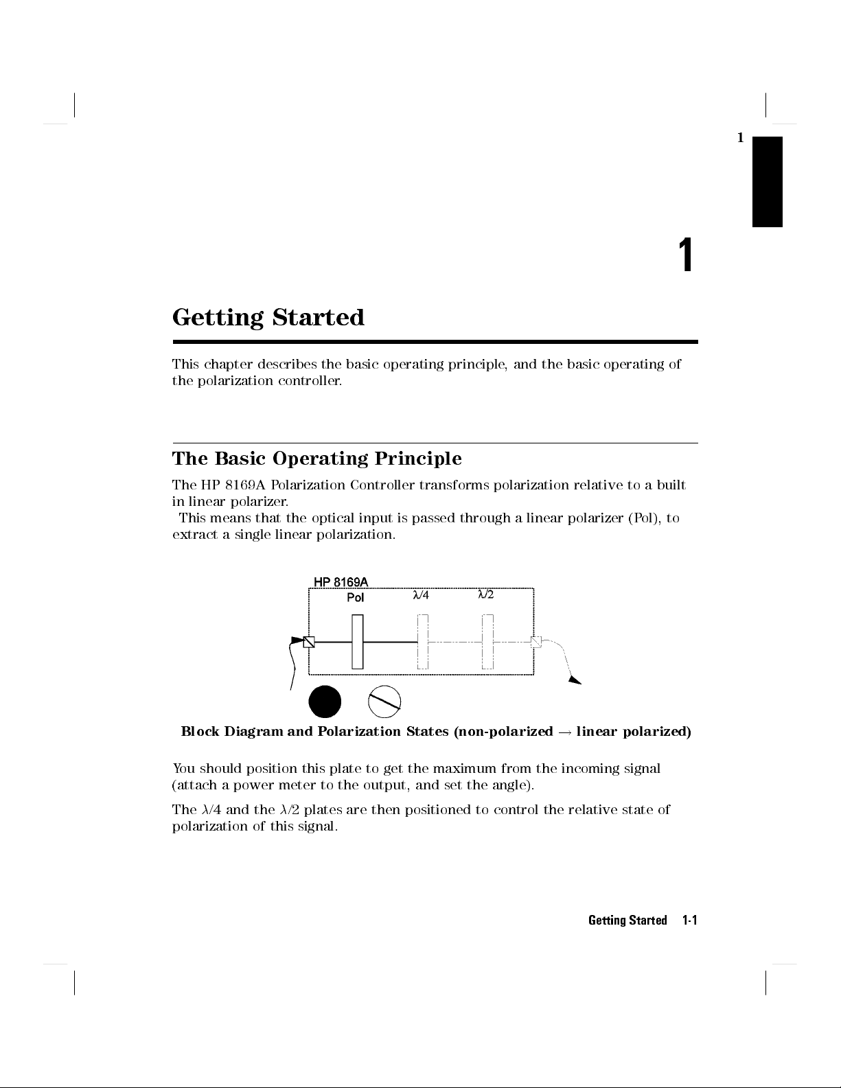
The Basic Operating Principle
The HP 8169A Polarization Controller transforms polarization relative to a built
in linear polarizer.
This means that the optical input is passed through a linear polarizer (P
extract a single linear polarization.
ol), to
1
Block Diagram and Polarization States (non-polarized!linear polarized)
You should position this plate to get the maximum from the incoming signal
(attach a power meter to the output, and set the angle).
The/4 and the/2 plates are then positioned to control the relative state of
polarization of this signal.
Getting Started 1-1
1
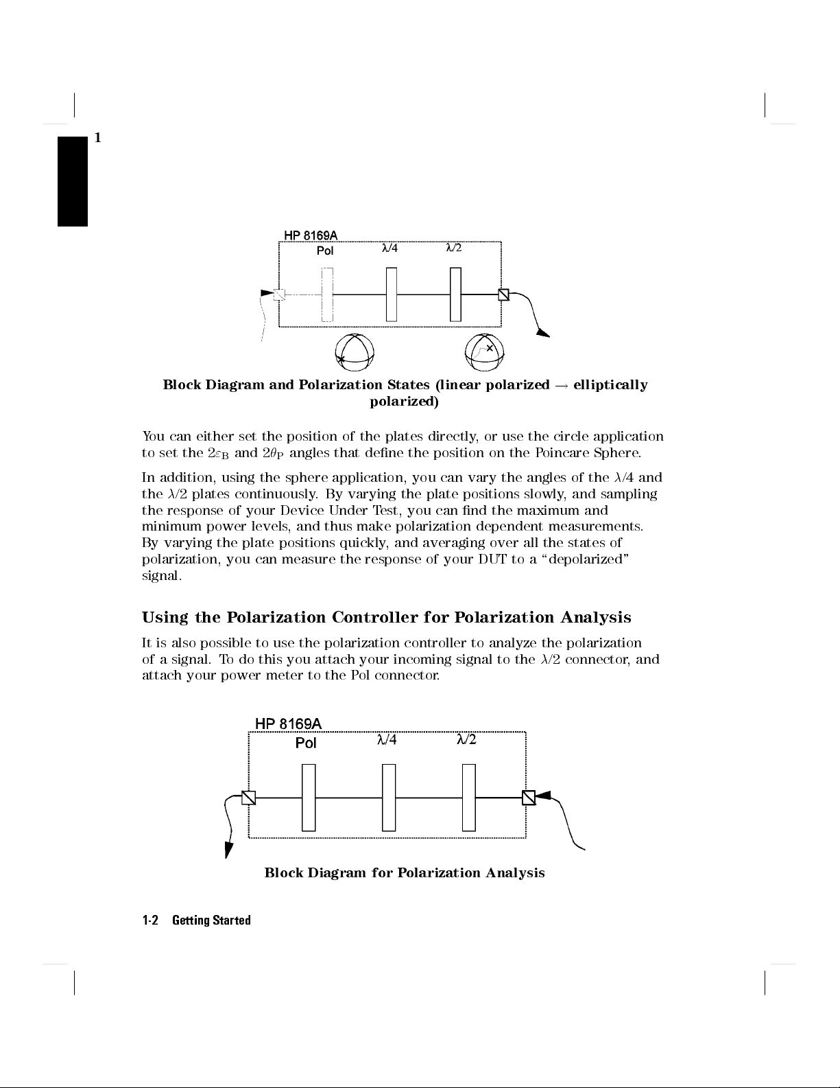
Block Diagram and Polarization States (linear polarized!elliptically
polarized)
You can either set the position of the plates directly, or use the circle application
to set the 2
In addition, using the sphere application, you can vary the angles of the/4 and
the/2 plates continuously. By varying the plate positions slowly, and sampling
the response of your Device Under Test, you can nd the maximum and
minimum power levels, and thus make polarization dependent measurements.
By varying the plate positions quickly, and averaging over all the states of
polarization, you can measure the response of your DUT to a \depolarized"
signal.
"Band 2
Pangles that dene the position on the Poincare Sphere.
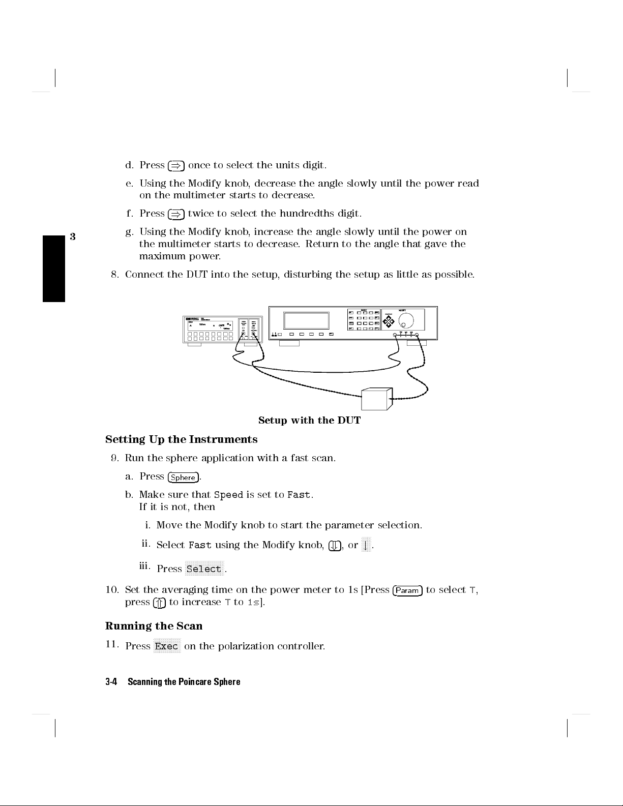
Using the Polarization Controller for Polarization Analysis
It is also possible to use the polarization controller to analyze the polarization
of a signal. To do this you attach your incoming signal to the/2 connector, and
attach your power meter to the Pol connector.
Block Diagram for Polarization Analysis
1-2 Getting Started

You analyze the signal by varying the/4 and/2 plates and the polorizer lter,
and examining how this aects the power. It is beyond the scope of this manual
to explain this topic in detail.
Editing
You can edit a parameter by using
the Entry keys,
the Cursor/Vernier keys,or
the Modify knob.
Editing Using the Entry Keys
1. Make sure the correct parameter is selected (the label of the selected
parameter is displayed inverse).
1
2. Type in the new value.
5
3. Press
4
Enter
.
If you mistype the number, you can move the cursor left and right using the
5
5
Cursor keys (
and
4
(
If you want to abort editing, without changing the parameter, press
If the parameter changes back to its old value when you press
).
4
)
NNNNNNNNNNNNNNNNNNN
N
Cancel
4
5
, then the
Enter
new value would be out of the range allowed for that parameter.
Editing Using the Modify Keys and Knob
1. Make sure the correct parameter is selected (the label of the selected
parameter is displayed inverse).
2. Press any of the Cursor/Vernier keys, to activate editing.
5
5
3. Use the Cursor keys (
and
4
(
4. Change the value using the Vernier keys (
) to move to the rst digit you want to edit.
4
)
5
5
and
4
*
).
4
+
OR
Change the value using the Modify knob.
Getting Started 1-3
.

1
5. Repeat steps list item 3 to list item 4 as often as necessary.
6. Press
4
Enter
5
.
NNNNNNNNNNNNNNNNNNNN
If you want to abort editing, without changing the parameter, press
Cancel
.
If you cannot change a digit with the Vernier keys or the Modify knob, this
means that the new value would be out of the range allowed for the parameter.
Resetting Parameters
To reset any parameter
1. Make sure the correct parameter is selected (the label of the selected
parameter is displayed inverse).
NNNNNNNNNNNNNNNNNNNNNN
2.
To reset
N
Press
Default
Pol,/4,/2,2
.
5
, AND2
"
B
simultaneously, press
P
4
Home
.
1-4 Getting Started

Setting a State of Polarization
This chapter describes the two ways of setting a State of Polarization,
By positioning the polarizing lter, the/2, and the/4 plates.
By positioning the polarizing lter, and then specifying the desired position on
the Poincare sphere.
Setting up the Hardware
2
2
Note
Typically, you will connect the polarization controller directly after your source,
and before your device under test (DUT). Before connecting to the rest of your
measurement setup, you should set the position of the polarizing lter.
Setting the Position of the Polarizing Filter
The polarizing lter should be set to maximize the signal. This means aligning
the polarizing lter with the greatest linear polarization of the source. (Light
from laser sources is elliptically polarized).
When you are setting up your hardware, it is absolutely vital
that the bers are xed, and remain unmoved for the whole
of the measurement. Moving the bers changes the state of
polarization.
Setting a State of Polarization 2-1

2
Power as a function of the angle of linear polarization for laser light
1. Connect the output of the polarization controller to a power meter.
Setup for maximizing the test signal
2. With all the instruments turned on, press
4
Home
5
on the polarization
controller. This resets the positions of all the plates.
3.
Select the polarization lter.You may need to press
4
Pos
5
and/or
NNNNNNNNNNN
Pol
if the
lter is not already selected.
4. Move the lter to nd the maximum signal through the polarization
controller. One way of doing this is
a. Press the right Cursor key twice to select the units digit.
b. Watching the power meter, and using the Modify knob, adjust the angle of
the polarization lter, until you are in the area of one of the maxima.
c. Select the tenths digit.
d. Watching the power meter, and using the Modify knob, adjust the angle of
the polarization lter, until you nd the maximum.
e. Select the hundredths digit, and adjust the angle of the polarization lter
if necessary to get the absolute maximum.
2-2 Setting a State of Polarization

5. Disconnect the power meter, and connect to your DUT, and the rest of your
measurement setup, making sure to move the bers as little as possible.
Setting the State of Polarization
The state of polarization of a signal can be described by a position on the
Poincare sphere. This position is can be expressed in spherical coordinates by
two angles, called
"Band
P.
2
Pis the optical angle about the 'equator' of the sphere (that is,2
angle of 'longitude').
"Bis half the angle of elevation from the equatorial plane (that is,2
angle of 'latitude').
The coordinates for describing the state of polarization
The state of polarization is always relative to the output from the polarizing
lter.
P
"
is the
is the
B
There are two ways of setting the state of polarization,
by specifying the position of the/4 and/2 retarder plates,or
by specifying
"Band
P, the coordinates on the Poincare sphere.
Setting a State of Polarization 2-3

2
Positioning the/4 and/2 Retarder Plates
You can set the state of polarization by positioning the/4, and/2 plates.
5
1. Select a retarder plate
with the plates.
Press
NNNNNNNNNNN
/4or
NNNNNNNNNNN
/2if the plate you want is not already selected.
.You may need to press
rst to get the display
4
Pos
2. Move the plate to the position you want. (See \Editing" in Chapter 1 if you
need information on changing the angles).
Using the Circle Mode
You can set the state of polarization by specifying the coordinates on the
Poincare sphere. See \Setting the State of Polarization" for an explanation.
5
1. Select an angle.You may need to press
angles.
Press
NNNNNNNNNN
2
"Bor
NNNNNNNNNN
2
Pif the angle you want is not already selected.
rst to get the display with the
4
Circle
2. Change the angle to the value you want. (See \Editing" in Chapter 1 if you
need information on changing the angles).
Example: Setting the Optimum Transmission SoP
To nd the state of polarization which gives optimum transmission for a linear
device under test (DUT), the steps are
i. Set the polarizing lter.
ii. Find the state of polarization for worst case transmission (this is easier to
nd, because the resolution allows greater accuracy at lower power).
iii. Set the state of polarization for optimum transmission.
For this example, you will need, apart from the polarization controller, a laser
source, and a power meter (in the description below, an HP 8153A Multimeter
with a laser module and a sensor module are used). We will use the length of
ber connecting the instruments as our linear DUT.
1. With both instruments switched o, connect the laser source to the
polarization controller.
2. Connect the polarization controller to the power meter.
2-4 Setting a State of Polarization

Setup for setting the position of the polarizing lter.
3. Switch on both instruments, and enable the laser source.
4. Set the channel with the sensor module to the wavelength of the source,
and select the default averaging speed (200ms).
2
Note
Under normal circumstances you should leave the instruments
to warmup. (The multimeter needs around 20 minutes to
warmup.) Warming up is necessary for accuracy of the sensor,
and the output power of the source.
Set the Polarizing Filter.
5
5. Press
6. Press
on the polarization controller.
4
Home
5
.
4
Pos
7. Set the angle of the polarizing lter for maximum throughput.
a. Type in10and press
b. Press
4)5
twice to select the tens digit.
4
Enter
5
.
c. Using the Modify knob, increase the angle slowly until the power read on
the multimeter increases and then starts to decrease.
5
d. Press
once to select the units digit.
4
)
e. Using the Modify knob, decrease the angle slowly until the power read
on the multimeter starts to decrease.
f. Press
4)5
twice to select the hundredths digit.
Setting a State of Polarization 2-5

2
g. Using the Modify knob
the multimeter starts to decrease
maximum power.
, increase the angle slowly until the power on
. Return to the angle that gave the
Setting the Worst Case Transmission SoP.
for the worst case transmission, because we can nd this more accurately (the
resolution of the power meter stays the same, but the full scale value is lower,
therefore we can be more accurate).
We also use the fact that the relationship between power of the signal
transmitted through the DUT and polarization on the surface of the sphere
can be expressed as concentric circles about the worst case (or optimum), and
that for a linear DUT the worst case and optimum are on opposite sides of the
sphere.
Power contours about the worst case on the poincare sphere
This means that we nd the worst case position by moving around the sphere
along the equator rst (that is nding the angle of longitude of the worst case)
and then the overall worst case by moving around this line of longitude.
We set the state of polarization
2-6 Setting a State of Polarization

Power contours with a search path to the worst case transmission state of
polarization
2
8.
Press
4
Circle
5
, and
NNNNNNN
P, to select
.
P
9. Search for the line of longitude with the minimum power (use a similar
method as for the position of the polarizing lter; rst changing the tens
,
then the units, then the hundredths).
Press
NNNNNNN
"B, to select
"B.
10.
11. Search for the angle of latitude with the minimum power.
Setting the Optimum Transmission SoP.
12. Read the value for
"Bfrom the display.
13. Add 180to this value.
14. Type in the new value, and press
4
Enter
5
.
The state of polarization is now set to the value for the current setup that gives
the greatest power through the ber. This is possible here because the ber
behaves linearly.For non-linear components the polarizations for worst case and
optimum transmission will not be on opposite sides of the sphere, and the angle
between them is a characteristic of the component.
Setting a State of Polarization 2-7


3
Scanning the Poincare Sphere
This chapter describes how you can use your polarization controller to measure
polarization dependence, and how you can generate quasi-depolarized signals.
Setting up the Hardware
Note
Typically, you will connect the polarization controller directly after your source,
and before your device under test (DUT). Before connecting to the rest of your
measurement setup, you should set the position of the polarizing lter (this is
described in \Setting the Position of the Polarizing Filter" in Chapter 2).
Setting Up and Executing a Scan
When you are setting up your hardware, it is absolutely vital
that the bers are xed, and remain unmoved for the whole
of the measurement. Moving the bers changes the state of
polarization.
3
The sphere application changes the state of polarization over time,by
rotating the/2 and/4 plates. The rotations can be done slowly, to give a
quasi-randomly polarized signal, which you can use, with suitable data logging
to measure polarization dependence. The rotations can be done quickly,to
give a quasi-depolarized signal, which you can use, with suitable measurement
averaging time to measure depolarized response.
1. Press
4
Sphere
5
to select the application.
Scanning the Poincare Sphere 3-1

The
Pol
Note
when you press
lter angle shown here is the same as the one shown
4
5
. If you have already set this value, there is
Pos
no need to change it.
2. Set the speed at which theplates rotate:
3
Set
SpeedtoFast
and the averaging time of your power meter to longer
than 1s to get measure the response to depolarized signal.
If it is not already selected:
a. Move the Modify knob.
b.
Select
c.
Press
Set
SpeedtoSlow
Fast
using the Modify knob,
NNNNNNNNNNNNNNNNNNNN
4
5
,or
Enter
Select
and the averaging time of your power meter as short as
4
+
.
5
,or
NNNNN
#
possible, and use logging to measure polarization dependence.
If it is not already selected:
a. Move the Modify knob.
N
b.
Select
c.
Press
3.
When everything is setup, press
Slow
using the Modify knob,
NNNNNNNNNNNNNNNNNNNN
4
5
,or
Enter
Select
.
NNNNNNNNNNNNNN
Exec
4
*
to start the scan.
5
,or
NNNN
"
During the scan, values for the angle of/4 and/2 are shown on the display.
These values are samples. Theplates rotate continuously.
Example: Measuring the Response to a \Depolarized" Signal
To measure the response to a \depolarized" signal for a device under test (DUT),
the steps are
i. Set the polarizing lter.
ii. Set the scanning speed to
Fast
.
iii. Set the averaging time of the power meter.
iv. Start the scan, and measure the value.
For this example, you will need, apart from the polarization controller, a laser
source, and a power meter (in the description below, an HP 8153A Multimeter
3-2 Scanning the Poincare Sphere

with a laser module and a sensor module are used). A roll of ber will act as a
suitable DUT.
1. With both instruments switched o, connect the laser source to the
polarization controller.
2. Connect the polarization controller to the power meter.
Setup for setting the position of the polarizing lter.
3. Switch on both instruments, and enable the laser source.
3
Note
Under normal circumstances you should leave the instruments
to warmup. (The multimeter needs around 20 minutes to
warmup.) Warming up is necessary for accuracy of the sensor,
and the output power of the source.
4. Set the channel with the sensor module to the wavelength of the source,
and select the default averaging speed (200ms) [Press
hold
4
5
Param
to resetT].
4
Param
5
to selectT,
Set the Polarizing Filter
5
5. Press
6. Press
4
4
on the polarization controller.
Home
5
.
Pos
7. Set the angle of the polarizing lter for maximum throughput.
5
a. Type in10and press
b. Press
4)5
twice to select the tens digit.
4
Enter
.
c. Using the Modify knob, increase the angle slowly until the power read on
the multimeter increases and then starts to decrease.
Scanning the Poincare Sphere 3-3
5
d. Press
once to select the units digit.
4
)
e. Using the Modify knob, decrease the angle slowly until the power read
on the multimeter starts to decrease.
f. Press
3
g. Using the Modify knob, increase the angle slowly until the power on
4)5
twice to select the hundredths digit.
the multimeter starts to decrease. Return to the angle that gave the
maximum power.
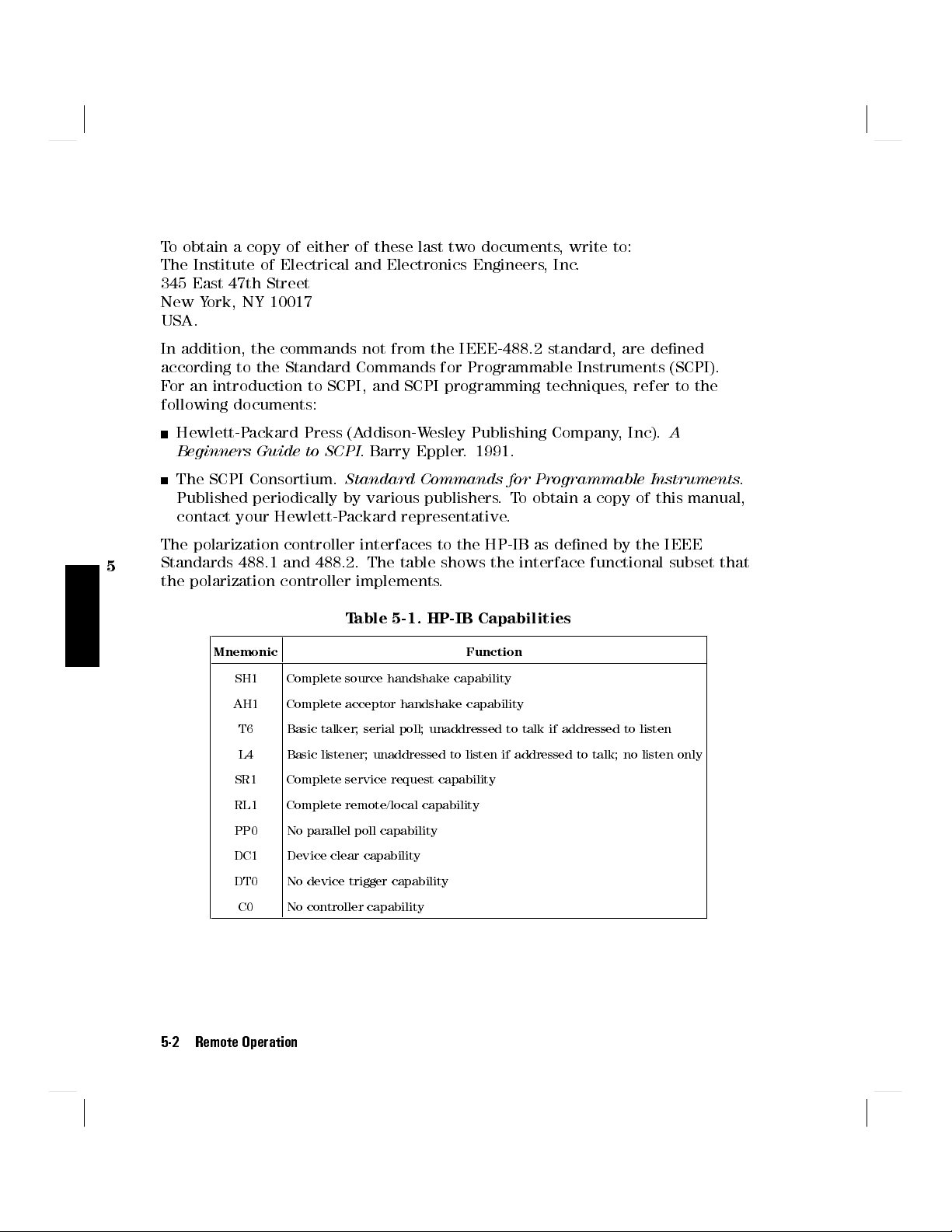
8. Connect the DUT into the setup, disturbing the setup as little as possible.
Setup with the DUT
Setting Up the Instruments
9. Run the sphere application with a fast scan.
a. Press
b. Make sure that
4
Sphere
5
.
Speed
is set to
Fast
.
If it is not, then
i. Move the Modify knob to start the parameter selection.
N
ii.
iii.
Select
Press
Fast
using the Modify knob,
NNNNNNNNNNNNNNNNNNNN
Select
.
4+5
,or
NNNN
#
.
10. Set the averaging time on the power meter to 1s [Press
press
4*5
to increaseTto1s].
Running the Scan
Press
N
Exec
on the polarization controller.
11.
NNNNNNNNNNNNN
3-4 Scanning the Poincare Sphere
4
Param
5
to selectT,

There is a slight delay while the application is initialized, and then the values of
/4 and/2 on the display begin to change.
12. When the application is running, read the value for the response of the DUT
to a depolarised signal from the display for the power sensor.
Example: Measuring a Polarization Dependent Loss
To measure the sensitivity to polarization, apply a quasi-random polarization to
the (DUT), the steps are
i. Set the polarizing lter.
ii. Set the scanning speed to
iii. Set the power meter to record.
iv. Start the scan, and record the readings for dierent polarization states.
v. Analyze the results.
For this example, you will need, apart from the polarization controller, a laser
source, and a power meter (in the description below, an HP 8153A Multimeter
with a laser module and a sensor module are used). A roll of ber will act as a
suitable DUT.
1. With both instruments switched o, connect the laser source to the
polarization controller.
2. Connect the polarization controller to the power meter.
Slow
.
3
Setup for setting the position of the polarizing lter.
3. Switch on both instruments, and enable the laser source.
Scanning the Poincare Sphere 3-5

Note
Under normal circumstances you should leave the instruments
to warmup. (The multimeter needs around 20 minutes to
warmup.) Warming up is necessary for accuracy of the sensor,
and the output power of the source.
3
4. Set the channel with the sensor module to the wavelength of the source,
and select the default averaging speed (200ms) [Press
hold
4
5
to resetT].
Param
4
Param
5
to selectT,
Set the Polarizing Filter
5. Press
6. Press
4
5
on the polarization controller.
Home
4
5
.
Pos
7. Set the angle of the polarizing lter for maximum throughput.
5
a. Type in10and press
5
b. Press
twice to select the tens digit.
4
)
4
Enter
.
c. Using the Modify knob, increase the angle slowly until the power read on
the multimeter increases and then starts to decrease.
d. Press
4)5
once to select the units digit.
e. Using the Modify knob, decrease the angle slowly until the power read
on the multimeter starts to decrease.
f. Press
4)5
twice to select the hundredths digit.
g. Using the Modify knob, increase the angle slowly until the power on
the multimeter starts to decrease. Return to the angle that gave the
maximum power.
8. Connect the DUT into the setup, disturbing the setup as little as possible.
3-6 Scanning the Poincare Sphere

Setup with the DUT
Setting Up the Instruments
9. Run the sphere application with a slow scan.
5
a. Press
4
Sphere
.
3
b. Make sure that
Speed
is set to
Slow
.
If it is not, then
i. Move the Modify knob to start the parameter selection.
ii.
iii.
Select
Press
Slow
using the Modify knob,
NNNNNNNNNNNNNNNNNNNN
Select
.
4
10. Set the averaging time on the power meter to 20ms [Press
5
and
to set it to 20ms].
4
+
11. Set up a Stability measurement over 20 seconds [Press
select
STABILTY
AUTODUMPtoOFF
. Press
]
4
Edit
5
to select
T TOTAL
NNNNN
"
5
,or
*
, and set it to
.
5
to selectT,
Param
5
, and
00:00:20
4
Record
5
to
, set
4
Menu
4
Running the Scan
Press
NNNNNNNNNNNNNN
Exec
on the polarization controller.
12.
There is a slight delay while the application is initialized, and then the values of
/4 and/2 on the display begin to change.
13. When the scan is running, start the recording [Press
4
Exec
5
].
Analyzing the Results
Scanning the Poincare Sphere 3-7

14. When the recording is nished look at the results and nd the dierence
between the highest and lowest [Press
then
4
5
twice to get
Next
This is the Polarization Dependent Loss for the DUT.
3
DIFF
].
4
More
5
to get
SHOW
, press
4
Edit
5
, and
3-8 Scanning the Poincare Sphere

4
Other Front Panel Functions
This chapter covers setting the HP-IB address for the polarization controller, and
storing and recalling instrument settings.
Setting the HP-IB Address
4
You can see or edit the HP-IB address of the instrument by pressing
4
Syst
5
.
The default HP-IB address is 24.
Storing or Recalling Instrument Settings
NNNNNNNNNNNNNNNNNNNNNNN
Press
4
Syst
5
and them
STO/RCL
to see the actual, current setting of the
instrument, the default setting for the instrument, and the 9 stored settings for
the instrument.
View the various settings by using
NNNNNNNNNNNNNNNNNNNNNNNNN
N
Previous
and
NNNNNNNNNNNNN
N
Next
.
Storing a Setting
To store the actual instrument setting,
1. Find one of the nine numbered settings, which you can overwrite using
NNNNNNNNNNNNNNNNNNNNNNNNNN
Previous
2.
Press
NNNNNNNNNNNNNNNNN
Store
and
.
NNNNNNNNNNNNNN
Next
.
Other Front Panel Functions 4-1

Recalling a Setting
To recall a setting and make it the actual instrument setting,
1.
Find the setting you want to restore, using
Press
NNNNNNNNNNNNNNNNNNNN
Recall
.
2.
NNNNNNNNNNNNNNNNNNNNNNNNNN
Previous
and
NNNNNNNNNNNNNN
Next
.
Resetting the Instrument
Resetting the instrument returns all the parameters to their default values (the
polarization lter and both wavelength plates are reset to 0.00and the speed
4
for the sphere application is set to
Fast
.
To reset the instrument, you can either
1.
Find the actual setting, using
Press
NNNNNNNNNNNNNNNNNNNNNNN
Default
.
2.
NNNNNNNNNNNNNNNNNNNNNNNNNN
Previous
and
NNNNNNNNNNNNNN
Next
.
or
1. Find the default setting, using
Press
NNNNNNNNNNNNNNNNNNNN
Recall
.
2.
NNNNNNNNNNNNNNNNNNNNNNNNNN
Previous
and
NNNNNNNNNNNNNN
Next
.
4-2 Other Front Panel Functions

5
Programming the Polarization Controller
This chapter gives general information on how to control the polarization
controller remotely. Descriptions for the actual commands for the polarization
controller are given in the following chapters. The information in these chapters
is specic to the polarization controller.
HP-IB Interface
The interface used by the polarization controller is the HP-IB (Hewlett-P
ackard
Interface Bus).
This is the interface used for communication between a controller and an
external device, such as the polarization controller. The HP-IB conforms to IEEE
standard 488-1978, ANSII standard MC 1.1 and IEC recommendation 625-1.
The information in these chapters assumes that you are already familiar with
programming over the HP-IB. If you are not familiar with the HP-IB, then refer
to the following books:
Hewlett-Packard Company.
Bus
, 1987.
The International Institute of Electrical and Electronics Engineers.
Tutorial Description of Hewlett-Packard Interface
IEEE
Standard 488.1-1987, IEEE Standard Digital Interface for Programmable
Instrumentation
The International Institute of Electrical and Electronics Engineers.
. New York, NY, 1987
IEEE
Standard 488.2-1987, IEEE Standard Codes,Formats, Protocols and Common
Commands For Use with ANSI/IEEE Std 488.1-1987
. New York, NY, 1987
5
Remote Operation 5-1
To obtain a copy of either of these last two documents, write to:
The Institute of Electrical and Electronics Engineers, Inc.
345 East 47th Street
New York, NY 10017
USA.
In addition, the commands not from the IEEE-488.2 standard, are dened
according to the Standard Commands for Programmable Instruments (SCPI).
For an introduction to SCPI, and SCPI programming techniques, refer to the
following documents:
Hewlett-Packard Press (Addison-Wesley Publishing Company, Inc).
Beginners Guide to SCPI
The SCPI Consortium.
. Barry Eppler. 1991.
Standard Commands for Programmable Instruments
A
.
Published periodically by various publishers.To obtain a copy of this manual,
contact your Hewlett-Packard representative.
The polarization controller interfaces to the HP-IB as dened by the IEEE
5
Standards 488.1 and 488.2. The table shows the interface functional subset that
the polarization controller implements.
Table 5-1. HP-IB Capabilities
Mnemonic Function
SH1 Complete source handshake capability
AH1 Complete acceptor handshake capability
T6 Basic talker; serial poll; unaddressed to talk if addressed to listen
L4 Basic listener; unaddressed to listen if addressed to talk; no listen only
SR1 Complete service request capability
RL1 Complete remote/local capability
PP0 No parallel poll capability
DC1 Device clear capability
DT0 No device trigger capability
C0 No controller capability
5-2 Remote Operation

Setting the HP-IB Address
You can only set the HP-IB address from the front panel. See \Setting the HP-IB
Address" in Chapter 4.
The default HP-IB address is 24.
Returning the Instrument to Local Control
If the instrument has been operated in remote the only key you can use is
NNNNNNNNNNNNNNNN
N
Local
. The
NNNNNNNNNNNNNNNN
N
Local
key returns the instrument to local control.
NNNNNNNNNNNNNNNN
N
Local
does
not operate if local lockout has been enabled.
How the Polarization Controller Receives and
Transmits Messages
The polarization controller exchanges messages using an input and an output
queue. Error messages are kept in a separate error queue.
How the Input Queue Works
The input queue is a FIFO queue (rst-in rst-out). Incoming bytes are stored in
the input queue as follows:
1. Receiving a byte:
a. Clears the output queue.
b. Clears Bit 7 (MSB).
2. No modication is made inside strings or binary blocks. Outside strings and
binary blocks, the following modications are made:
5
a. Lower-case characters are converted to upper-case.
b. The characters 0016to 0916and 0B16to 1F16are converted to spaces
(2016).
c. Two or more blanks are truncated to one.
Remote Operation 5-3

3. An EOI (End Or Identify) sent with any character is put into the input queue
as the character followed by a line feed (LF,0A
). If EOI is sent with a LF,
16
only one LF is put into the input queue.
4. The parser starts if the LF character is received or if the input queue is full.
Clearing the Input Queue
Switching the power o, or sending a Device Interface Clear signal, causes
commands that are in the input queue, but have not been executed to be lost.
The Output Queue
The output queue contains responses to query messages. The polarization
controller transmits any data from the output queue when a controller
addresses the instrument as a talker.
Each response message ends with a LF (0A16), with EOI=TRUE. If no query is
5
received, or if the query has an error, the output queue remains empty.
The Message Available bit (MAV, bit 4) is set in the Status Byte register
whenever there is data in the output queue.
The Error Queue
The error queue is a FIFO queue (rst-in rst-out). That is, the rst error read is
the oldest error to have occurred.
If too many errors are put into the queue, the message '-350<Queue
Overow>' is placed as the last message in the queue.
Some Notes about Programming and Syntax Diagram
Conventions
A program message is a message containing commands or queries that you send
to the polarization controller. The following are a few points about program
messages:
You can use either upper-case or lower-case characters.
You can send several commands in a single message. Each command must be
separated from the next one by a semicolon (;).
5-4 Remote Operation

You end a program message with a line feed (LF) character, or any character
sent with End-Or-Identify (EOI).
Short Form and Long Form
The instrument accepts messages in short or long forms
message
:DISP:ENAB ON
:DISPLAY:ENABLE ON
.
is in long form, the short form of this message is
.For example, the
In this manual the messages are written in a combination of upper and lower
case. Upper case characters are used for the short form of the message
example, the above command would be written
:DISPlay:ENABle
.For
.
The rst colon can be left out for the rst command or query in your message.
That is, the example given above could also be sent as
DISP:ENAB ON
.
Command and Query Syntax
All characters not between angled brackets must be sent exactly as shown.
The characters between angled brackets (<...>) show the kind of data that
you send, or that you get in a response.You do not type the angled brackets in
the actual message. Descriptions of these items follow the syntax description.
The most common of these are:
string is ascii data. A string is contained between a " at the start and the
end, or a ' at the start and the end.
value is numeric data in integer (12), decimal (34.5) or exponential format
(67.8E-9).
wsp is a white space.
5
Other kinds of data are described as required.
The characters between square brackets ([ . . . ]) show optional information that
you can include with the message.
The bar (j) shows an either-or choice of data, for example,ajbmeans eitheraor
b
, but not both simultaneously.
Extra spaces are ignored; they can be inserted to improve readability.
Remote Operation 5-5


Remote Commands
This chapter gives a list of the remote commands, for use with the HP-IB.
In the remote command descriptions the parts given in upper-case characters
must be given. The parts in lower-case characters can also be given, but they
are optional.
6
6
Remote Commands 6-1

Command Summary
Table 6-1. Common Command Summary
Command Parameter/Response Min Max Function
*CLS
*ESE
*ESE?
*ESR?
*IDN?
*OPC
*OPC?
*RCL
*RST
*SAV
*SRE
*SRE?
*STB?
6
*TST?
*WAI
<
value
<
value
<
value
<
string
<
value
<
location
<
location
<
value
<
value
<
value
<
value
Clear Status Command
>
>
>
>
0 255 Standard Event Status Enable Command
0 255 Standard Event Status Enable Query
0 255 Standard Event Status Register Query
Identication Query
Operation Complete Command
>
>
0 9 Recall Instrument Setting
Operation Complete Query
Reset Command
>
>
>
>
>
1 9 Save Instrument Setting
0 255 Service Request Enable Command
0 255 Service Request Enable Query
0 255 Read Status Byte Query
0 65535 Self Test Query
Wait Command
6-2 Remote Commands

Table 6-2. Command List
Command Parameter
:ABORt
:DISPlay
:ENABle OFFj0jONj1
:ENABle? 0j1
:INITiate
[
[
:INPut
:IMMediate
]
]
:CIRCle
:EPSilonb
:EPSilonb?
:THETap
:THETap?
:POSition
:HALF
:HALF?
:POLarizer
:POLarizer?
:QUARter
:QUARter?
:PSPHere
:RATE 0j1 0 1 1
:RATE? 0j1
:STATus
:OPERation
:CONDition?
:ENABle
:ENABle?
[
:EVENt]?
:NTRansition
:NTRansition?<value
:PTRansition
:PTRansition?<value
:PRESet
Response
<
value
>
<
value
>
<
value
>
<
value
>
<
value
>
<
value
>
<
value
>
<
value
>
<
value
>
<
value
>
<
value
>
<
value
>
<
value
>
<
value
>
<
value
>
>
<
value
>
>
Unit
MINimum MAXimum DEFault
y
-720.00 720.00 0.00
y
y
-2160.00 2160.00 0.00
y
y
-360.00 360.00 0.00
y
y
-360.00 360.00 0.00
y
y
-360.00 360.00 0.00
y
0 65535 0
0 65535 0
0 65535 0
6
Remote Commands 6-3

Table 6-2. Command List (continued)
Command Parameter
Unit
MINimum MAXimum DEFault
Response
:STATus
:QUEStionable
:CONDition?
:ENABle
:ENABle?
[
:EVENt]?
:NTRansition
:NTRansition?<value
:PTRansition
:PTRansition?<value
<
value
<
value
<
value
<
value
<
value
<
value
>
>
0 65535 0
>
>
>
0 65535 0
>
>
0 65535 0
>
:SYSTem
:ERRor?
:VERSion?
y
No unit is specied, but
<
value
>
[always returns 1994.0]
all values are in degrees.
6
6-4 Remote Commands

The Common Commands
The IEEE 488.2 standard has a list of reserved commands
commands. These are the commands that start with an asterisk. Some of these
commands must be implemented by any instrument using the standard, others
are optional. This section describes the implemented commands
Common Status Information
There are four registers for the common status information. Two of these are
status-registers and two are enable-registers. These registers conform to the
IEEE Standard 488.2-1987
under \*ESE", \*ESR?", \*SRE", and \*STB?".
The following gure shows how the registers are organized.
Status Register
.You can nd further descriptions of these registers
, called common
.
6
Remote Commands 6-5

6
Figure 6-1. Common Status Registers
*
The questionable and operation status trees are described in \STATus
Commands".
Note
SRQ, The Service Request
A service request (SRQ) occurs when a bit in the Status Byte register goes from
0!1
The Request Service (RQS) bit is set to1at the same time that the SRQ is
caused. This bit can only be reset by reading it by a serial poll. The RQS bit is
6-6 Remote Commands
AND the corresponding bit in the Service Request Enable Mask is set.
Unused bits in any of the registers return 0 when you read
them.

not aected by the condition that caused the SRQ. The serial poll command
transfers the value of the Status Byte register to a variable.
*CLS
Syntax
Denition
Example
*ESE
Syntax
Denition
*CLS
The *CLS command clears the following:
Standard event status register (ESR)
Status byte register (STB)
The Error Queue
After the
*CLS
command the instrument is left waiting for the
next command. The instrument setting is unaltered by the
command, though
If the
*CLS
command occurs directly after a program message
*OPC/*OPC?
actions are canceled.
terminator, the output queue and MAV, bit 4, in the status byte
register are cleared, and if condition bits 2-0 of the status byte
register are zero, MSS, bit 6 of the status byte register is also
zero.
OUTPUT 724;"*CLS"
*ESE<wsp><value
>
0value255
The
*ESE
command sets bits in the standard event status enable
register (ESE) that enable the corresponding bits in the standard
event status register (ESR).
6
The register is cleared:
At power-on
By sending a value of zero
The register is not changed by the
*RST
and
*CLS
commands.
Remote Commands 6-7

*ESE?
The Event Status Enable Register
BIT MNEMONIC BIT VALUE
7 Power On 128
6 User Request 64
5 Command Error 32
4 Execution Error 16
3 Device dependent Error 8
2 Query Error 4
1 Request Control 2
0 Operation Complete 1
The standard event status enable query returns the contents of
the standard event status enable register.
Example
6
*ESR?
Syntax
Denition
OUTPUT 724;"*ESE 21"
OUTPUT 724;"*ESE?"
ENTER 724; A$
*ESR?
The standard event status register query returns the contents of
the standard event status register. The register is cleared after
being read.
0contents255
6-8 Remote Commands
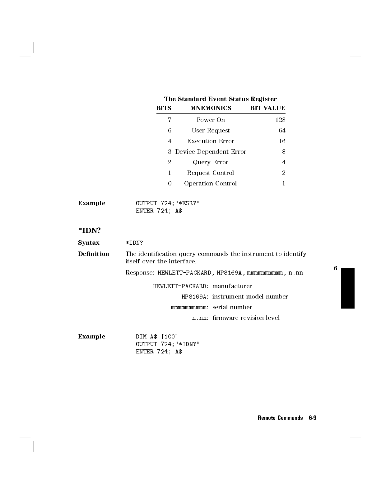
The Standard Event Status Register
BITS MNEMONICS BIT VALUE
7 Power On 128
6 User Request 64
4 Execution Error 16
3 Device Dependent Error 8
2 Query Error 4
1 Request Control 2
0 Operation Control 1
Example
*IDN?
Syntax
Denition
Example
OUTPUT 724;"*ESR?"
ENTER 724; A$
*IDN?
The identication query commands the instrument to identify
itself over the interface.
Response:
HEWLETT-PACKARD, HP8169A, mmmmmmmmmm, n.nn
HEWLETT-PACKARD
HP8169A
mmmmmmmmmm
: manufacturer
: instrument model number
: serial number
n.nn
: rmware revision level
DIM A$ [100]
OUTPUT 724;"*IDN?"
ENTER 724; A$
6
Remote Commands 6-9

*OPC
Syntax
Denition
*OPC
The instrument parses and executes all program message units
in the input queue and sets the operation complete bit in the
standard event status register (ESR). This command can be used
to avoid lling the input queue before the previous commands
have nished executing.
Example
OUTPUT 724;"*CLS;*ESE 1;*SRE 32"
OUTPUT 724;"*OPC"
*OPC?
This query causes all the program messages in the input queue
to be parsed and executed. Once it has completed it places an
ASCII '1' in the output queue. There is a short delay between
interpreting the command and putting the '1' in the queue.
Example
OUTPUT 724;"*CLS;*ESE 1;*SRE 32"
OUTPUT 724;"*OPC?"
ENTER 724;A$
6
*RCL
Syntax
*RCL<wsp
><
location
>
0location9
Denition
An instrument setting from the internal RAM is made the actual
instrument setting (this does not include HP-IB address or
parser).
You recall user settings from locations 1-9. See \*SAV". Location
0 contains the default setting, which is the same as that
obtained by
Example
OUTPUT 724;"*RCL 3"
6-10 Remote Commands
*RST
.
*RST
Syntax
Denition
*RST
The reset setting (default setting) stored in ROM is made the
actual setting.
Instrument state: the instrument is placed in the idle state
awaiting a command.
The following are not changed:
HP-IB (interface) state
Instrument interface address
Output queue
Service request enable register (SRE)
Standard event status enable register (ESE)
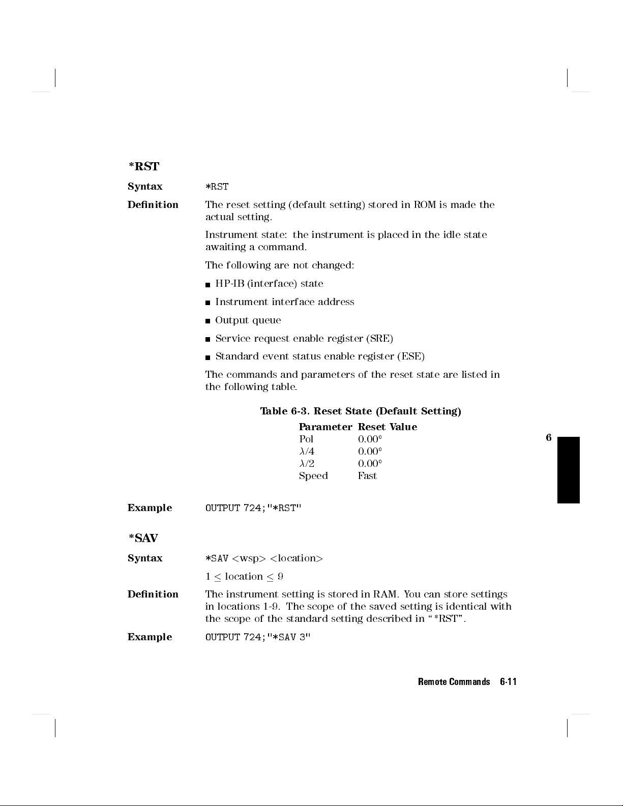
The commands and parameters of the reset state are listed in
the following table.
Table 6-3. Reset State (Default Setting)
Parameter Reset Value
Pol 0.00
/4 0.00
/2 0.00
Speed Fast
6
Example
*SAV
Syntax
Denition
Example
OUTPUT 724;"*RST"
*SAV<wsp
><
location
>
1location9
The instrument setting is stored in RAM. You can store settings
in locations 1-9. The scope of the saved setting is identical with
the scope of the standard setting described in \*RST".
OUTPUT 724;"*SAV 3"
Remote Commands 6-11

*SRE
Syntax
*SRE<wsp
><
value
>
0value255
Denition
The service request enable command sets bits in the service
request enable register that enable the corresponding status
byte register bits.
The register is cleared:
At power-on
By sending a value of zero.
The register is not changed by the
*RST
and
*CLS
commands.
The Service Request Enable Register
BITS MNEMONICS BIT VALUE
7 Operation Status 128
6 Request Status 64
5 Event Status Byte 32
6
4 Message Available 16
3 Questionable Status 8
2 Not used 0
Note
Bit 6 cannot be masked.
*SRE?
The service request enable query returns the contents of the
service request enable register.
Example
6-12 Remote Commands
1 Not used 0
0 Not used 0
OUTPUT 724;"*SRE 48"
*STB?
OUTPUT 724;"*SRE?"
ENTER 724; A$
Syntax
Denition
Example
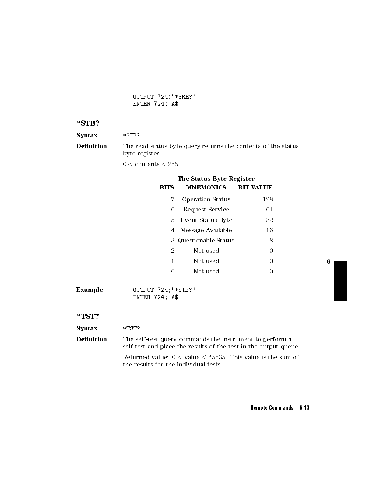
*STB?
The read status byte query returns the contents of the status
byte register.
0contents255
The Status Byte Register
BITS MNEMONICS BIT VALUE
7 Operation Status 128
6 Request Service 64
5 Event Status Byte 32
4 Message Available 16
3 Questionable Status 8
2 Not used 0
1 Not used 0
0 Not used 0
OUTPUT 724;"*STB?"
ENTER 724; A$
6
*TST?
Syntax
Denition
*TST?
The self-test query commands the instrument to perform a
self-test and place the results of the test in the output queue.
Returned value: 0value65535. This value is the sum of
the results for the individual tests
Remote Commands 6-13
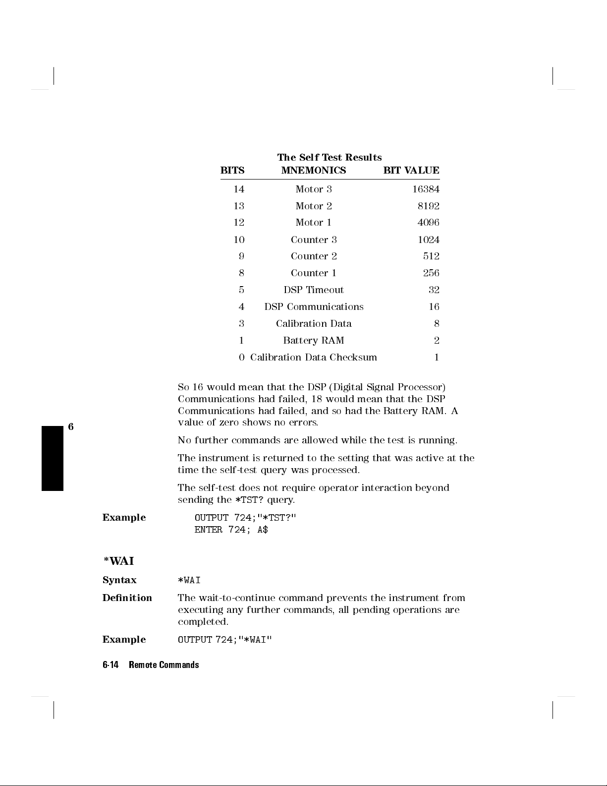
The Self Test Results
BITS MNEMONICS BIT VALUE
14 Motor 3 16384
13 Motor 2 8192
12 Motor 1 4096
10 Counter 3 1024
9 Counter 2 512
8 Counter 1 256
5 DSP Timeout 32
4 DSP Communications 16
3 Calibration Data 8
1 Battery RAM 2
0 Calibration Data Checksum 1
So 16 would mean that the DSP (Digital Signal Processor)
Communications had failed, 18 would mean that the DSP
Communications had failed, and so had the Battery RAM. A
6
value of zero shows no errors.
No further commands are allowed while the test is running.
The instrument is returned to the setting that was active at the
time the self-test query was processed.
The self-test does not require operator interaction beyond
sending the
Example
*WAI
Syntax
Denition
*WAI
The wait-to-continue command prevents the instrument from
executing any further commands, all pending operations are
completed.
Example
OUTPUT 724;"*WAI"
6-14 Remote Commands
*TST?
query.
OUTPUT 724;"*TST?"
ENTER 724; A$

Switching On and O the Instrument Display
These are the commands for enabling or disabling the display on the instrument.
:DISPlay:ENABle
Syntax
Description
:DISPlay:ENABle?
Syntax
Description
Example
:DISPlay:ENABle<wsp>OFFjONj0j1
This command enables or disables the front panel display.
Set the state to
toONor1to switch the display on. The default is for the
display to be on.
:DISPlay:ENABle?
The query returns the current state of the display.
A returned value of0shows that the display is o. A returned
value of1shows that the display is on.
OFFor0
OUTPUT 724;":DISP:ENAB ON"
OUTPUT 724;":DISP:ENAB?"
ENTER 724;A$
to switch the display o, set the state
6
Remote Commands 6-15

Positioning the Polarizing Filter
These are the commands that deal with the position of the polarizing lter
.
[:INPut]:POSition:POLarizer
Syntax
[
:INPut]:POSition:POLarizer<wsp
<
value>j
MINimumjMAXimumjDEFault
>
where value is a oating point number between -360.00 and
360.00.
Description
This command sets the position of the polarizing lter. The
parameter may be either
a number, in mechanical degrees (do not give a unit; the
number will be rounded to the nearest 0.05),
MINimum
MAXimum
DEFault
(-360.00),
(360.00), or
).
(0.00
[:INPut]:POSition:POLarizer?
6
Syntax
Description
[
:INPut]:POSition:POLarizer?
This query gets the position of the polarizing lter in mechanical
degrees (without a unit).
Example
OUTPUT 724;"POS:POL 127"
6-16 Remote Commands
OUTPUT 724;"POS:POL?"
ENTER 724;A$
Setting the State of Polarization
These are the commands that deal with positioning the
/4 and/2 retarder
plates, and setting the state of polarization by specifying the coordinates on the
Poincare sphere.
[:INPut]:CIRCle:EPSilonb
Syntax
[
:INPut]:CIRCle:EPSilonb<wsp
<
value>j
MINimumjMAXimumjDEFault
>
where value is a oating point number between -720.00 and
720.00.
Description
This command sets the 2
"Bposition on of the Poincare sphere.
The parameter may be either
a number, in optical degrees (do not give a unit; the number
will be rounded to the nearest 0.05),
), or
),
"B.
Note
MINimum
MAXimum
DEFault
(-720.00
(720.00
(0.00).
The value you specify with this command is for 2
6
[:INPut]:CIRCle:EPSilonb?
Syntax
Description
[
:INPut]:CIRCle:EPSilonb?
This query gets the 2
optical degrees (without a unit).
Note
The value returned by this query is for 2
"Bposition on the Poincare sphere in
.
"
B
Remote Commands 6-17

[:INPut]:CIRCle:THETap
Syntax
[
:INPut]:CIRCle:THETap<wsp
<
value>j
MINimumjMAXimumjDEFault
>
where value is a oating point number between -2160.00 and
2160.00.
Description
This command sets the position of the 2
Pposition on the
Poincare sphere. The parameter may be either
a number, in optical degrees (do not give a unit; the number
will be rounded to the nearest 0.05),
),
), or
).
.
P
Note
MINimum
MAXimum
DEFault
(-2160.00
(2160.00
(0.00
The value you specify with this command is for 2
[:INPut]:CIRCle:THETap?
6
Syntax
Description
[
:INPut]:CIRCle:THETap?
This query gets the position of the 2
Pposition on the Poincare
sphere in optical degrees (without a unit).
Note
The value returned by this query is for 2
Example
6-18 Remote Commands
P.
OUTPUT 724;":CIRC:EPS 128"
OUTPUT 724;":CIRC:THET 270"
OUTPUT 724;":CIRC:EPS?"
ENTER 724;E$
OUTPUT 724;":CIRC:THET?"
ENTER 724;T$

[:INPut]:POSition:HALF
Syntax
[
:INPut]:POSition:HALF<wsp
<
value>j
MINimumjMAXimumjDEFault
where value is a oating point number between -360.00 and
360.00.
Description
This command sets the position of the/2 retarder plate. The
parameter may be either
a number, in mechanical degrees (do not give a unit; the
number will be rounded to the nearest 0.05),
MINimum
MAXimum
DEFault
(-360.00
(360.00
(0.00
[:INPut]:POSition:HALF?
Syntax
Description
[
:INPut]:POSition:HALF?
This query gets the position of the/2 retarder plate in
mechanical degrees (without a unit).
[:INPut]:POSition:QUARter
Syntax
[
:INPut]:POSition:QUARter<wsp
<
value>j
MINimumjMAXimumjDEFault
where value is a oating point number between -360.00 and
360.00.
).
), or
>
),
6
>
Description
This command sets the position of the/4 retarder plate. The
parameter may be either
a number, in mechanical degrees (do not give a unit; the
number will be rounded to the nearest 0.05),
MINimum
MAXimum
DEFault
(-360.00),
(360.00), or
(0.00).
Remote Commands 6-19

[:INPut]:POSition:QUARter?
Syntax
Description
Example
6
[
:INPut]:POSition:QUARter?
This query gets the position of the/4 retarder plate in
mechanical degrees (without a unit).
OUTPUT 724;":POS:QUAR 64"
OUTPUT 724;":POS:HALF 99.5"
OUTPUT 724;":POS:QUAR?"
ENTER 724;Q$
OUTPUT 724;":POS:HALF?"
ENTER 724;H$
6-20 Remote Commands

Scanning the Sphere
These are the commands for varying the state of polarization automatically over
time.
[:INPut]:PSPHere:RATE
Syntax
Description
[
:INPut]:PSPHere:RATE<wsp>0j1
This command sets the speed at which the the state of
polarization is changed.
0
set the speed to slow (for polarization dependent
measurements), or
1
sets the speed to fast (for quasi-depolarized signals).
[:INPut]:PSPHere:RATE?
Syntax
Description
[
:INPut]:PSPHere:RATE?
This query gets the the speed at which the the state of
polarization is set to change.
0
if the speed is set to slow.
1
if the speed is set to fast, or
:INITiate[:IMMediate]
Syntax
Description
:INITiate[:IMMediate
This command starts the application.
:ABORt
6
]
Syntax
Description
Example
:ABORt
This command aborts an application that is running.
OUTPUT 724;":PSPH:RATE 1"
OUTPUT 724;":INIT"
.
.
.
OUTPUT 724;":PSPH:RATE?"
ENTER 724;R$
.
.
.
Remote Commands 6-21

OUTPUT 724;":ABOR"
6
6-22 Remote Commands

STATus Commands
There are two `nodes' in the status circuitry
The OPERation node shows things that can happen during normal operation.
The QUEStionable node shows error conditions
Each node of the status circuitry has ve registers:
A condition register (CONDition), which contains the current status. This
register is updated continuously. It is not changed by having its contents read.
The event register (EVENt), which contains the output from the transition
registers. The contents of this register are cleared when it is read.
A positive transition register (PTRansition), which, when enabled, puts a 1
into the event register, when the corresponding bit in the condition register
goes from 0 to 1.
The power-on condition for this register is for all the bits to be enabled.
A negative transition register (NTRansition), which, when enabled, puts a 1
into the event register, when the corresponding bit in the condition register
goes from 1 to 0.
The power-on condition for this register is for all the bits to be disabled.
The enable register (ENABle), which enables changes in the event register to
aect the Status Byte.
The status registers for the polarization controller are organized as shown:
.
.
6
Remote Commands 6-23

Figure 6-2. The Status Registers
6
Setting Up the STATus Registers
These are the commands for setting up the registers.
:STATus:PRESet
Syntax
Description
Example
6-24 Remote Commands
:STATus:PRESet
This command presets all the enable registers and transition
lters for both the OPERation and QUEStionable nodes.
All the bits in the ENABle registers are set to 0
All the bits in the PTRansition registers are set to 1
All the bits in the NTRansition registers are set to 0
OUTPUT 724;":STAT:PRES"
Only two bits of the OPERation node are used:
Bit 1 to show that the instrument is settling (that is that the polarizer and the
/4 and/2 plates have not reached position.
Bit 8 shows that an application is running.
:STATus:OPERation:NTRansition
Syntax
Description
:STATus:OPERation:NTRansition<wsp
This command sets the bits in the NTRansition register. Setting
a bit in this register enables a negative transition (1!0) in the
corresponding bit in the CONDition register to set the bit in the
EVENt register.
:STATus:OPERation:NTRansition?.
Syntax
Description
:STATus:OPERation:NTRansition?
This query returns the current contents of the
OPERation:NTRansition register.
:STATus:OPERation:PTRansition
Syntax
Description
:STATus:OPERation:PTRansition<wsp
This command sets the bits in the PTRansition register
a bit in this register enables a positive transition (0
corresponding bit in the CONDition register to set the bit in the
EVENt register.
:STATus:OPERation:PTRansition?.
Syntax
Description
:STATus:OPERation:PTRansition?
This query returns the current contents of the
OPERation:PTRansition register.
><
><
value
value
>
>
. Setting
!
1) in the
6
:STATus:OPERation:ENABle
Syntax
Description
:STATus:OPERation:ENABle<wsp
This command sets the bits in the ENABle register that
enable the contents of the EVENt register to aect the Status
Byte (STB). Setting a bit in this register to 1 enables the
corresponding bit in the EVENt register to aect bit 7 of the
Status Byte.
><
value
>
Remote Commands 6-25

:STATus:OPERation:ENABle?.
Syntax
Description
Example
6
:STATus:OPERation:ENABle?
This query returns the current contents of the
OPERation:ENABle register.
OUTPUT 724;":STAT:OPER:NTR 2"
OUTPUT 724;":STAT:OPER:PTR 256"
OUTPUT 724;":STAT:OPER:ENAB 258"
OUTPUT 724;":STAT:OPER:NTR?"
ENTER 724;N$
OUTPUT 724;":STAT:OPER:PTR?"
ENTER 724;P$
OUTPUT 724;":STAT:OPER:ENAB?"
ENTER 724;E$
6-26 Remote Commands

Only one bit of the QUEStionable node is used:
Bit 8 shows that there is an error in the calibration data.
:STATus:QUEStionable:NTRansition
Syntax
Description
:STATus:QUEStionable:NTRansition<wsp
This command sets the bits in the NTRansition register. Setting
a bit in this register enables a negative transition (1!0) in the
corresponding bit in the CONDition register to set the bit in the
EVENt register.
:STATus:QUEStionable:NTRansition?.
Syntax
Description
:STATus:QUEStionable:NTRansition?
This query returns the current contents of the
QUEStionable:NTRansition register.
:STATus:QUEStionable:PTRansition
Syntax
Description
:STATus:QUEStionable:PTRansition<wsp
This command sets the bits in the PTRansition register. Setting
a bit in this register enables a positive transition (0!1) in the
corresponding bit in the CONDition register to set the bit in the
EVENt register.
:STATus:QUEStionable:PTRansition?.
Syntax
Description
:STATus:QUEStionable:PTRansition?
This query returns the current contents of the
QUEStionable:PTRansition register.
><
><
value
value
>
>
6
:STATus:QUEStionable:ENABle
Syntax
Description
:STATus:QUEStionable:ENABle<wsp
This command sets the bits in the ENABle register that
enable the contents of the EVENt register to aect the Status
Byte (STB). Setting a bit in this register to 1 enables the
corresponding bit in the EVENt register to aect bit 3 of the
Status Byte.
><
value
>
Remote Commands 6-27

:STATus:QUEStionable:ENABle?.
Syntax
Description
Example
6
:STATus:QUEStionable:ENABle?
This query returns the current contents of the
QUEStionable:ENABle register.
OUTPUT 724;":STAT:QUES:NTR 256"
OUTPUT 724;":STAT:QUES:PTR 256"
OUTPUT 724;":STAT:QUES:ENAB 256"
OUTPUT 724;":STAT:QUES:NTR?"
ENTER 724;N$''
OUTPUT 724;":STAT:QUES:PTR?"
ENTER 724;P$''
OUTPUT 724;":STAT:QUES:ENAB?"
ENTER 724;E$
6-28 Remote Commands

Checking the Status
These commands are for checking the status of the instrument, as reported in
the OPERational and QUEStionable ST
ATus registers.
Note
See also \The Common Commands" for the standard IEEE 488.2
status registers.
:STATus:OPERation:CONDition?
Syntax
Description
:STATus:OPERation:CONDition?
This query reads the contents of the OPERation:CONDition
register. Only two bits of the condition register are used:
BITS MNEMONICS BIT VALUE
Example
OUTPUT 724;":STAT:OPER:COND?"
ENTER 724;A$
:STATus:OPERation[:EVENt]?
Syntax
Description
:STATus:OPERation[:EVENt]?
This query reads the contents of the OPERation:EVENt register.
Only two bits of the event register are used (whether these
bits contain information depends on the transition register
conguration):
8 Settling 256
1 Application 2
6
Example
BITS MNEMONICS BIT VALUE
8 Settling 256
1 Application 2
OUTPUT 724;":STAT:OPER?"
ENTER 724;A$
Remote Commands 6-29

:STATus:QUEStionable:CONDition?
Syntax
Description
Example
:STATus:QUEStionable[:EVENt]?
Syntax
Description
6
Example
:STATus:QUEStionable:CONDition?
This query reads the contents of the QUEStionable:CONDition
register. Only one bit of the condition register is used:
BITS MNEMONICS BIT VALUE
8 Calibration Data 256
OUTPUT 724;":STAT:QUES:COND?"
ENTER 724;A$
:STATus:QUEStionable[:EVENt]?
This query reads the contents of the QUEStionable:EVENt
register. Only one bit of the event register is used (whether
these bits contain information depends on the transition register
conguration):
BITS MNEMONICS BIT VALUE
8 Calibration Data 256
OUTPUT 724;":STAT:QUES?"
ENTER 724;A$
6-30 Remote Commands

SYSTem Commands
:SYSTem:ERRor?
Syntax
Description
:SYSTem:ERRor?
This query returns the next error from the error queue (see
\The Error Queue" in Chapter 5). Each error has the error code
and a short description of the error, separated by a comma, for
example
-32768 and +32767. Negative error numbers are dened by the
SCPI standard. Positive error numbers are device dependent.
The errors are listed in Appendix F
Example
OUTPUT 724;":SYST:ERR?"
ENTER 724;A$
:SYSTem:VERSion?
Syntax
Description
:SYSTem:VERSion?
This query returns the version of the SCPI command set being
used in the format
the version. For this instrument, the value returned is always
1994.0
Example
OUTPUT 724;":SYST:VERS?"
ENTER 724;A$
0, "No error"
yyyy.v
. Error codes are numbers in the range
, where
yyyy
is the year, andvis
6
Remote Commands 6-31

Programming Examples
This chapter gives some programming examples. The language used for the
programming is BASIC 5.1 Language System used on HP 9000 Series 200/300
computers.
These programming examples do not cover the full command set for the
instrument. They are intended only as an introduction to the method of
programming the instrument. The programming examples use the HP-IB
.
7
Programming Examples 7-1
7

Example 1 - Checking Communication
Function
This program sends a query
, and displays the reply.
Listing
10 !-------------------------------
20 !
30 ! HP 8169A Programming Example 1
40 !
50 ! A Simple Communications Check
60 !
70 !-------------------------------
80 !
90 ! Definitions and initialization
100 !
110 Pol=724
This statement sets the address of the polarization controller. The rst 7 is to access the HP-IB card in
the controller, the 24 is it's HP-IB address
120 DIM String$[50]
130 !
150 PRINT TABXY(5,10);"Programming Example 1, Simple Communications"
160 !
170 ! Send an IDN query and get the Identification
180 !
190 OUTPUT Pol;"*IDN?"
7
200 ENTER Pol;String$
210 PRINT TABXY(10,12);"Identification : ";String$
220 !
230 END
7-2 Programming Examples

Example 2 - Status Registers and Queues
Example 2 - Status Registers and Queues
Function
This program sends a commands and queries typed in by the user. The contents
of the status byte and the standard event status register are displayed. These
registers are updated for each new command, and each time a Service ReQuest
(SRQ) occurs. The number of the most recent error, and the most recent
contents of the output queue is also displayed.
Listing
10 !--------------------------------------------------
20 !
30 ! HP 8169A Programming Example 2
40 !
50 ! Status Structure, and a useful self learning tool
60 !
70 !--------------------------------------------------
80 !
90 ! Declarations and initializations
100 !
110 INTEGER Value,Bit,Quot,Xpos,Ypos
120 DIM Inp$[100]
130 DIM A$[300]
140 Pol=724
150 ON INTR 7 GOSUB Pmm_srq
160 !
170 ! Mask the registers
180 !
190 OUTPUT Pol;"*SRE 248;*ESE 255"
The *SRE 248 command enables bits 7 (Operation Status Summary), 5 (ESB), 4 (MAV), and 3
(Questionable Status Summary) in the status byte (bit 6 (SRQ) cannot be disabled in this register).
The *ESE 255 command enables all of the bits in the Event Status Register.
200 !
210 ! Set up the screen
220 !
230 CLEAR SCREEN
240 PRINT TABXY(40,3);"Status Byte"
250 PRINT TABXY(4,1);" OPS SRQ ESB MAV QUE"
260 PRINT TABXY(4,2);" +---+---+---+---+---+---+---+---+"
270 PRINT TABXY(4,3);" : : : : : : : : :"
280 PRINT TABXY(4,4);" +---+---+---+---+---+---+---+---+"
290 PRINT TABXY(4,5);" ^"
7
Programming Examples 7-3

Example 2 - Status Registers and Queues
300 PRINT TABXY(4,6);" :"
310 PRINT TABXY(4,7);" +-------------------------------+"
320 PRINT TABXY(4,8);" : OR :"
330 PRINT TABXY(4,9);" +-------------------------------+"
340 PRINT TABXY(4,10);" ^ ^ ^ ^ ^ ^ ^ ^"
350 PRINT TABXY(4,11);" +---+---+---+---+---+---+---+---+"
360 PRINT TABXY(4,12);" : : : : : : : : :"
370 PRINT TABXY(4,13);" +---+---+---+---+---+---+---+---+"
380 PRINT TABXY(4,14);" PON URQ CME EXE DDE QYE RQC OPC"
390 PRINT TABXY(40,12);"Standard Event Status Register"
400 PRINT TABXY(4,16);"Last Command :"
410 PRINT TABXY(4,17);"Last Error :"
420 PRINT TABXY(4,18);"Output Queue :"
430 !
440 ! Start the program loop and enable the interrupt for the errors
450 !
460 Ende=0
470 GOSUB Pmm_srq
480 ENABLE INTR 7;2
490 !
500 ! The Central Loop
510 !
520 REPEAT
530 INPUT "Command ? ",Inp$
540 GOSUB Pmm_srq
550 OUTPUT Pol;Inp$
560 PRINT TABXY(21,16);" "
570 PRINT TABXY(21,16);Inp$
580 WAIT 1.0
590 UNTIL Ende=1
600 GOTO 1380
7
610 !
620 !--------------------------------------------------------------------
630 Pmm_srq: ! Interrupt Handling Subroutine to display the status, and the
640 ! error and output queues
650 !--------------------------------------------------------------------
660 !
670 ! Get the value for the Status Byte
680 !
690 Value=SPOLL(Pol)
700 !
710 ! Initialize and start the display of the registers
720 !
730 PRINT TABXY(21,17);" "
740 PRINT TABXY(21,18);" "
750 Ypos=3
7-4 Programming Examples

Example 2 - Status Registers and Queues
760 FOR Z=0 TO 1
770 Bit=128
780 Xpos=7
790 !
800 ! Do it for each bit
810 !
820 REPEAT
830 Quot=Value DIV Bit
840 !
850 ! If the bit is set then display 1
860 !
870 IF Quot>0 THEN
880 PRINT TABXY(Xpos,Ypos);"1"
890 Value=Value-Bit
900 !
910 ! If MAV is set, then get and display the output queue contents
920 !
930 IF Z=0 THEN
940 IF Bit=16 THEN
950 ENTER Pol;A$
960 PRINT TABXY(21,18);A$
970 END IF
980 END IF
990 !
1000 ! If the bit is not set, then display 0
1010 !
1020 ELSE
1030 PRINT TABXY(Xpos,Ypos);"0"
1040 END IF
1050 !
1060 ! Set up for the next iteration
1070 !
1080 Bit=Bit DIV 2
1090 Xpos=Xpos+4
1100 UNTIL Bit=0
1110 !
1120 ! Now that the status byte is displayed, get the Standard Events
1130 ! Status Register
1140 !
1150 OUTPUT Pol;"*ESR?"
1160 ENTER Pol;Value
1170 !
1180 ! Set up to display the ESR
1190 !
1200 Ypos=12
1210 NEXT Z
7
Programming Examples 7-5

Example 2 - Status Registers and Queues
1220 !
1230 ! Read and display any messages in the error queue
1240 !
1250 REPEAT
1260 OUTPUT Pol;"SYSTEM:ERROR?"
1270 ENTER Pol;Value,A$
The SYSTEM:ERROR? query gets the number of the last error in the error queue.
1280 IF Value<>0 THEN PRINT TABXY(21,17);Value,A$
1290 UNTIL Value=0
1300 !
1310 ! Clear the Status structure and reenable the interrupt before returning
1320 !
1330 OUTPUT Pol;"*CLS"
1340 ENABLE INTR 7
1350 !
1360 RETURN
1370 !
1380 END
7
7-6 Programming Examples

Example 3 - Finding the Optimum Transmission SoP
Example 3 - Finding the Optimum Transmission SoP
Function
This program performs the same sequence as the example session given in
chapter 2. That is, to nd the state of polarization for optimum transmission for
a linear device under test (DUT).
Requirements
For this example, you will need, apart from the polarization controller, a laser
source, and a power meter (in the description below, an HP 8153A Multimeter
with a laser module and a sensor module are used). We will use the length of
ber connecting the instruments as our linear DUT.
Setting Up the Equipment
1. With both instruments switched o, connect the laser source to the
polarization controller.
2. Connect the polarization controller to the power meter.
Setup for setting the position of the polarizing lter.
3. Switch on both instruments, and enable the laser source.
4. Set the channel with the sensor module to the wavelength of the source, and
select the default averaging speed (200ms).
Programming Examples 7-7
7

Example 3 - Finding the Optimum Transmission SoP
Note
Under normal circumstances you should leave the instruments
to warmup. (The multimeter needs around 20 minutes to
warmup.) Warming up is necessary for accuracy of the sensor,
and the output power of the source.
Listing
10 !------------------------------------------
20 !
30 ! Programming Example 3
40 !
50 ! Finding the Optimum Transmission Polarization
60 !
70 !------------------------------------------
80 !
90 ! Definitions and Initializations
100 !
110 Pol=724
120 Mm=722
130 !
140 OUTPUT Mm;"*rst;*cls"
150 OUTPUT Pol;"*rst;*cls"
160 !
170 ! Setup the instruments, with the output of the source connected
180 ! to the input of the sensor and wait for the ENTER key to be
190 ! pressed before continuing
200 !
210 CLEAR SCREEN
220 True=1
230 False=0
240 !
7
250 ! Set the Wavelength and the averaging time for the sensor
260 !
270 OUTPUT Mm;"sour:pow:wave?"
280 ENTER Mm;Wl
290 OUTPUT Mm;"sens2:pow:wave ";Wl
300 OUTPUT Mm;"sens2:pow:atime 200ms"
310 !
320 ! Switch on the source
330 !
340 OUTPUT Mm;"sour:pow:state on"
350 !
360 ! Find the position of the polarizing filter, that allows the maximum
370 ! power through
380 !
390 Angle=0
7-8 Programming Examples

Example 3 - Finding the Optimum Transmission SoP
400 Inc=10
410 Maxward=False
420 OUTPUT Mm;"read2:power?"
430 ENTER Mm;Maxpow
440 REPEAT
450 Angle=Angle+Inc
460 OUTPUT Pol;"pos:pol ";Angle
470 OUTPUT Mm;"read2:power?"
480 ENTER Mm;Newpow
490 IF Newpow<Maxpow THEN
500 IF Maxward=True THEN
510 Inc=-Inc/2
520 ELSE
530 Inc=-Inc
540 Maxward=True
550 END IF
560 ELSE
570 Maxpow=Newpow
580 Maxward=True
590 END IF
600 UNTIL ABS(Inc)<.05
610 !
620 ! Now search for the worst-case polarization when changing thetap
630 !
640 Angle=0
650 Inc=10
660 Minward=False
670 Minpow=Maxpow
680 REPEAT
690 Angle=Angle+Inc
700 OUTPUT Pol;"circle:thetap ";Angle
710 OUTPUT Mm;"read2:power?"
720 ENTER Mm;Newpow
730 IF Newpow>Minpow THEN
740 IF Minward=True THEN
750 Inc=-Inc/2
760 ELSE
770 Inc=-Inc
780 Minward=True
790 END IF
800 ELSE
810 Minpow=Newpow
820 Minward=True
830 END IF
840 UNTIL ABS(Inc)<.05
850 !
860 ! Now search for the overall worst-case polarization by changing epsilonb
870 !
880 Angle=0
7
Programming Examples 7-9
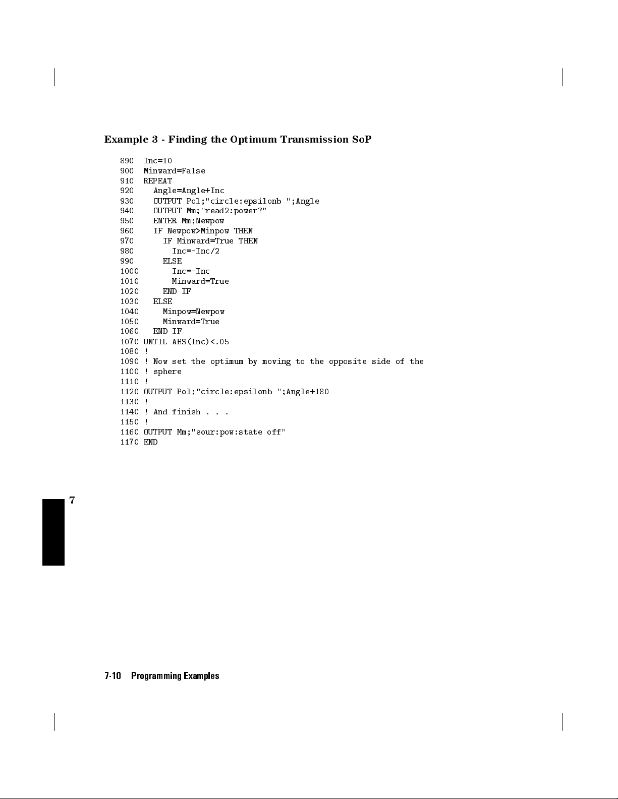
Example 3 - Finding the Optimum Transmission SoP
890 Inc=10
900 Minward=False
910 REPEAT
920 Angle=Angle+Inc
930 OUTPUT Pol;"circle:epsilonb ";Angle
940 OUTPUT Mm;"read2:power?"
950 ENTER Mm;Newpow
960 IF Newpow>Minpow THEN
970 IF Minward=True THEN
980 Inc=-Inc/2
990 ELSE
1000 Inc=-Inc
1010 Minward=True
1020 END IF
1030 ELSE
1040 Minpow=Newpow
1050 Minward=True
1060 END IF
1070 UNTIL ABS(Inc)<.05
1080 !
1090 ! Now set the optimum by moving to the opposite side of the
1100 ! sphere
1110 !
1120 OUTPUT Pol;"circle:epsilonb ";Angle+180
1130 !
1140 ! And finish . . .
1150 !
1160 OUTPUT Mm;"sour:pow:state off"
1170 END
7
7-10 Programming Examples

Example 4 - Finding the P
Example 4 - Finding the Polarization Dependence
Function
This program does the same thing as the example session given in chapter 3.
That is, to measure the sensitivity to polarization, by applying a quasi-random
polarization to the (DUT).
Requirements
For this example, you will need, apart from the polarization controller, a laser
source, and a power meter (in the description below, an HP 8153A Multimeter
with a laser module and a sensor module are used). A roll of ber will act as a
suitable DUT.`
Setting Up the Equipment
1. With both instruments switched o, connect the laser source to the
polarization controller.
2. Connect the polarization controller to the power meter.
olarization Dependence
Setup for setting the position of the polarizing lter.
3. Switch on both instruments, and enable the laser source.
Note
Under normal circumstances you should leave the instruments
to warmup. (The multimeter needs around 20 minutes to
warmup.) Warming up is necessary for accuracy of the sensor,
and the output power of the source.
Programming Examples 7-11
7
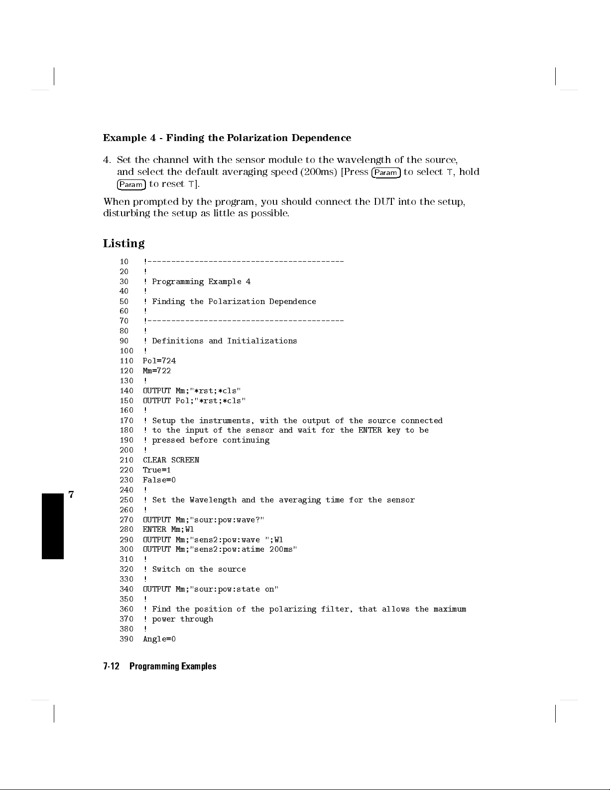
Example 4 - Finding the P
olarization Dependence
4. Set the channel with the sensor module to the wavelength of the source,
and select the default averaging speed (200ms) [Press
4
5
to resetT].
Param
4
Param
5
to selectT, hold
When prompted by the program, you should connect the DUT into the setup,
disturbing the setup as little as possible.
Listing
10 !------------------------------------------
20 !
30 ! Programming Example 4
40 !
50 ! Finding the Polarization Dependence
60 !
70 !------------------------------------------
80 !
90 ! Definitions and Initializations
100 !
110 Pol=724
120 Mm=722
130 !
140 OUTPUT Mm;"*rst;*cls"
150 OUTPUT Pol;"*rst;*cls"
160 !
170 ! Setup the instruments, with the output of the source connected
180 ! to the input of the sensor and wait for the ENTER key to be
190 ! pressed before continuing
200 !
210 CLEAR SCREEN
220 True=1
230 False=0
7
240 !
250 ! Set the Wavelength and the averaging time for the sensor
260 !
270 OUTPUT Mm;"sour:pow:wave?"
280 ENTER Mm;Wl
290 OUTPUT Mm;"sens2:pow:wave ";Wl
300 OUTPUT Mm;"sens2:pow:atime 200ms"
310 !
320 ! Switch on the source
330 !
340 OUTPUT Mm;"sour:pow:state on"
350 !
360 ! Find the position of the polarizing filter, that allows the maximum
370 ! power through
380 !
390 Angle=0
7-12 Programming Examples
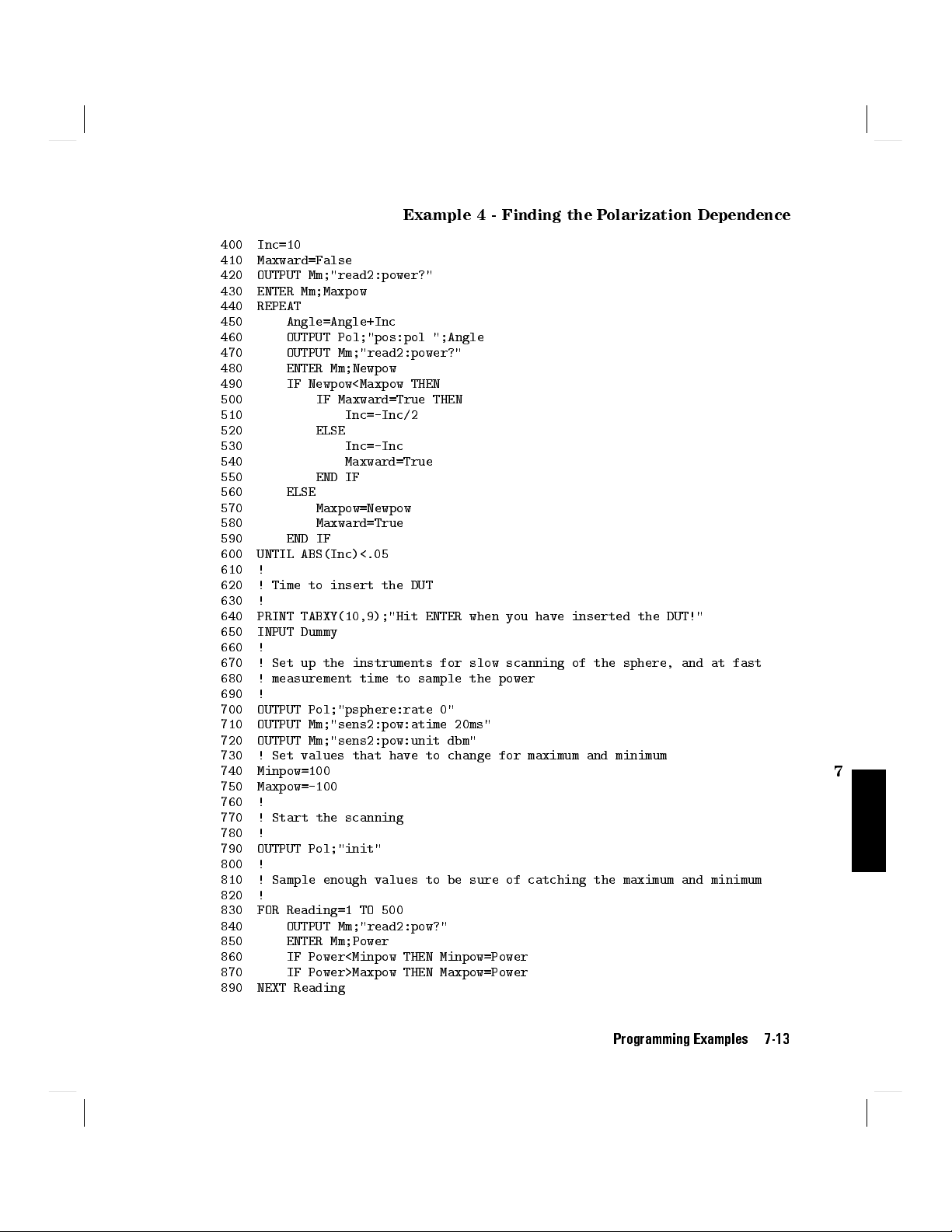
Example 4 - Finding the P
olarization Dependence
400 Inc=10
410 Maxward=False
420 OUTPUT Mm;"read2:power?"
430 ENTER Mm;Maxpow
440 REPEAT
450 Angle=Angle+Inc
460 OUTPUT Pol;"pos:pol ";Angle
470 OUTPUT Mm;"read2:power?"
480 ENTER Mm;Newpow
490 IF Newpow<Maxpow THEN
500 IF Maxward=True THEN
510 Inc=-Inc/2
520 ELSE
530 Inc=-Inc
540 Maxward=True
550 END IF
560 ELSE
570 Maxpow=Newpow
580 Maxward=True
590 END IF
600 UNTIL ABS(Inc)<.05
610 !
620 ! Time to insert the DUT
630 !
640 PRINT TABXY(10,9);"Hit ENTER when you have inserted the DUT!"
650 INPUT Dummy
660 !
670 ! Set up the instruments for slow scanning of the sphere, and at fast
680 ! measurement time to sample the power
690 !
700 OUTPUT Pol;"psphere:rate 0"
710 OUTPUT Mm;"sens2:pow:atime 20ms"
720 OUTPUT Mm;"sens2:pow:unit dbm"
730 ! Set values that have to change for maximum and minimum
740 Minpow=100
750 Maxpow=-100
760 !
770 ! Start the scanning
780 !
790 OUTPUT Pol;"init"
800 !
810 ! Sample enough values to be sure of catching the maximum and minimum
820 !
830 FOR Reading=1 TO 500
840 OUTPUT Mm;"read2:pow?"
850 ENTER Mm;Power
860 IF Power<Minpow THEN Minpow=Power
870 IF Power>Maxpow THEN Maxpow=Power
890 NEXT Reading
7
Programming Examples 7-13

Example 4 - Finding the P
900 !
910 ! Calculate (and display) the difference
920 !
930 PRINT TABXY(10,12);"Polarization Dependence",Maxpow-Minpow;"dB"
940 !
950 ! Tidy up and leave
960 !
970 OUTPUT Pol;"abort"
980 OUTPUT Mm;"sour:pow:state off"
990 END
olarization Dependence
7
7-14 Programming Examples
A
Installation
This appendix provides installation instructions for the polarization controller.
It also includes information about initial inspection and damage claims,
preparation for use, packaging, storage, and shipment.
Safety Considerations
The polarization controller is a Class 1 instrument (that is, an instrument with
an exposed metal chassis directly connected to earth via the power supply
cable). The symbol used to show a protective earth terminal in the instrument is
.
Before operation, review the instrument and manual for safety markings and
instructions.You must follow these to ensure safe operation and to maintain the
instrument in safe condition.
Initial Inspection
Inspect the shipping container for damage. If there is damage to the container
or cushioning, keep them until you have checked the contents of the shipment
for completeness and veried the instrument both mechanically and electrically.
The Appendix D gives a procedure for checking the operation of the instrument.
If the contents are incomplete, mechanical damage or defect is apparent,
or if an instrument does not pass the operator's checks, notify the nearest
Hewlett-Packard oce.
Installation A-1
A
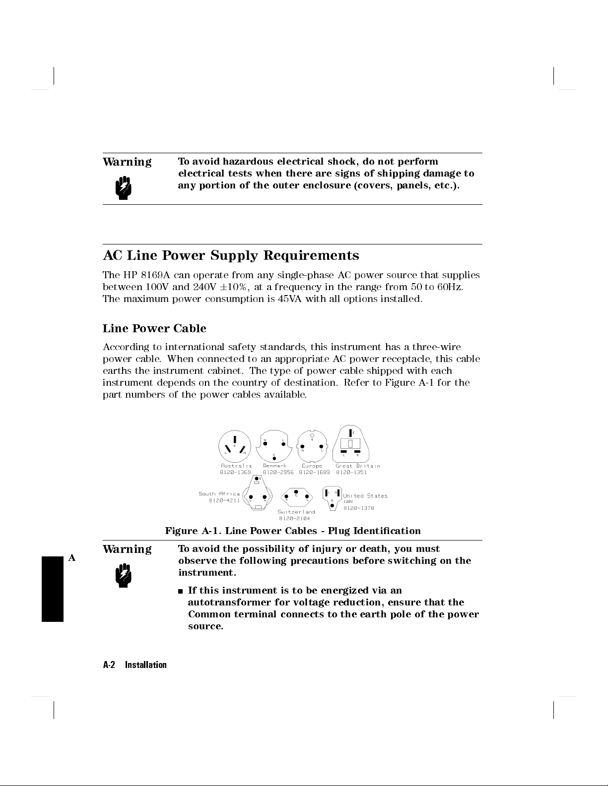
Warning
AC Line Power Supply Requirements
The HP 8169A can operate from any single-phase AC power source that supplies
between 100V and 240V610%, at a frequency in the range from 50 to 60Hz.
The maximum power consumption is 45VA with all options installed.
Line Power Cable
According to international safety standards, this instrument has a three-wire
power cable. When connected to an appropriate AC power receptacle, this cable
earths the instrument cabinet. The type of power cable shipped with each
instrument depends on the country of destination. Refer to Figure A
part numbers of the power cables available.
To avoid hazardous electrical shock, do not perform
electrical tests when there are signs of shipping damage to
any portion of the outer enclosure (covers, panels, etc.).
-1 for the
A
Warning
A-2 Installation
Figure A-1. Line Power Cables - Plug Identication
To avoid the possibility of injury or death, you must
observe the following precautions before switching on the
instrument.
If this instrument is to be energized via an
autotransformer for voltage reduction, ensure that the
Common terminal connects to the earth pole of the power
source.

Insert the power cable plug only into a socket outlet
provided with a protective earth contact. Do not negate
this protective action by the using an extension cord
without a protective conductor.
Before switching on the instrument, the protective
earth terminal of the instrument must be connected to a
protective conductor.You can do this by using the power
cord supplied with the instrument.
Do not interrupt the protective earth connection
intentionally.
The following work should be carried out by a qualied electrician. All local
electrical codes must be strictly observed. If the plug on the cable does not t
the power outlet, or if the cable is to be attached to a terminal block, cut the
cable at the plug end and rewire it.
The color coding used in the cable depends on the cable supplied. If you are
connecting a new plug, it should meet the local safety requirements and include
the following features:
Adequate load-carrying capacity (see table of specications).
Ground connection.
Cable clamp.
Warning
To avoid the possibility of injury or death, please note that
the HP 8169A does not have a oating earth.
Warning
The HP 8169A is not designed for outdoor use.To prevent
potential re or shock hazard, do not expose the instrument
to rain or other excessive moisture.
The AC power requirements are summarized on the rear panel of the
instrument.
Installation A-3
A

Figure A-2. Rear Panel Markings
Replacing the Fuse
There is one fuse in this instrument. This is a T1A/250V (time-lag) (HP Part No.
2110-0007). The fuse holder is at the rear of the instrument, beside the line
power connector.To replace the fuse,
1. Release the fuse holder: use the blade of a at-headed screwdriver to
depress the catch at the side of the holder and then pull the holder out a
little.
A
Figure A-3. Releasing the Fuse Holder
2. Pull the fuse holder out of the instrument.
A-4 Installation

Figure A-4. The Fuse Holder
3. Check and replace the fuse as necessary making sure that the fuse is always
in the top position of the fuse holder, and the bridge is in the bottom.
4. Place the fuse holder back in the instrument, and push it until the catch
clicks back into place.
Replacing the Battery
This instrument contains a lithium battery. Replacing the battery should be
carried out only by a qualied electrician or by HP service personnel.
There is a danger of explosion if the battery is incorrectly replaced. Replace
only with the same or an equivalent type (HP part number 1420-0394). Discard
used batteries according to local regulations.
Operating and Storage Environment
The following summarizes the HP 8169A operating environment ranges. In order
for the polarization controller to meet specications, the operating environment
must be within these limits.
A
Warning
The HP 8169A is not designed for outdoor use.To prevent
potential re or shock hazard, do not expose the instrument
to rain or other excessive moisture.
Installation A-5

Temperature
Protect the instrument from temperature extremes and changes in temperature
that may cause condensation within it.
The storage and operating temperature for the HP 8169A is given in the table
below.
Table A-1. Temperature
Operating Range Storage Range
Specied 0Cto55C -40Cto70C
Humidity
The operating humidity for the HP 8169A is 15% to 95% from 0Cto40C.
Altitude
The HP 8169A may operate at up to 10,000 feet.
Installation Category and Pollution Degree
The HP 8169A has Installation Category II and Pollution Degree 2 according to
IEC 664.
A
Instrument Positioning and Cooling
Mount or position the instrument upright and horizontally so that air can
circulate around it freely. When operating the polarization controller, choose a
location that provides at least 75mm (3inches) of clearance at the rear, and at
least 25mm (1inch) of clearance at each side.Failure to provide adequate air
clearance may result in excessive internal temperature, reducing instrument
reliability.
A-6 Installation

Figure A-5. Correct Positioning of the Polarization Controller
Switching on the Polarization Controller
When you switch on the polarization controller it goes through self test. This is
the same as the self test described in \*TST?" in Chapter 6.
Optical Output
Caution
The polarization controller is supplied with either a straight
contact connector (Option 021) or an angled contact connector
(Option 022). Make sure that you only use the correct cables
with your chosen output. See \Connector Interfaces and Other
Accessories" in Appendix B for further details on connector
interfaces and accessories.
A
Installation A-7

Trigger Input and Output
The Trigger Input should be a standard TTL level signal. That is
True = Low = digital ground or 0Vdc to 0.4Vdc
False = High = open or 2.5Vdc to 5Vdc
Caution
The Trigger Output is a standard TTL level signal.
Caution
HP-IB Interface
You can connect your HP-IB interface into a star network, a linear network, or a
combination star and linear network. The limitations imposed on this network
are as follows:
A maximum of610V can be applied as an external voltage to
the Trigger Input BNC connector.
A maximum of between 0V and +5V can be applied as an
external voltage to the Trigger Output BNC connector.
,
A
The total cable length cannot exceed 20 meters
The maximum cable length per device is 2 meters
No more than 15 devices may be interconnected on one bus.
A-8 Installation

Connector
The following gure shows the connector and pin assignments.
Connector Part Number: 1251-0293
Figure A-6. HP-IB Connector
Caution
Caution
HP-IB Logic Levels
The polarization controller HP-IB lines use standard TTL logic, as follows:
True = Low = digital ground or 0Vdc to 0.4Vdc
False = High = open or 2.5Vdc to 5Vdc
All HP-IB lines have LOW assertion states. High states are held at 3.0Vdc by
pull-ups within the instrument. When a line functions as an input, it requires
HP products delivered now are equipped with connectors
having ISO metric- threaded lock screws and stud mounts (ISO
M3.520.6) that are black in color. Earlier connectors may have
lock screws and stud mounts with imperial-threaded lock screws
and stud mounts (6-32 UNC) that have a shiny nickel nish.
It is recommended that you do not stack more than three
connectors, one on top of the other.
Hand-tighten the connector lock screws. Do not use a
screwdriver.
Installation A-9
A
approximately 3.2mA to pull it low through a closure to digital ground. When
a line functions as an output, it can sink up to 48mA in the low state and
approximately 0.6mA in the high state.
Note
The HP-IB line screens are not isolated from ground.
Claims and Repackaging
If physical damage is evident or if the instrument does not meet specication
when received, notify the carrier and the nearest Hewlett-Packard Service
Oce. The Sales/Service Oce will arrange for repair or replacement of the
unit without waiting for settlement of the claim against the carrier.
Return Shipments to HP
If the instrument is to be shipped to a Hewlett-P
ackard Sales/Service Oce,
attach a tag showing owner, return address, model number and full serial
number and the type of service required.
The original shipping carton and packing material may be reusable, but
the Hewlett-Packard Sales/Service Oce will provide information and
recommendation on materials to be used if the original packing is no longer
available or reusable. General instructions for repacking are as follows:
A
1. Wrap instrument in heavy paper or plastic.
2. Use strong shipping container. A double wall carton made of 350-pound test
material is adequate.
3. Use enough shock absorbing material (3 to 4 inch layer) around all sides
of the instrument to provide a rm cushion and prevent movement inside
container. Protect control panel with cardboard.
4. Seal shipping container securely.
5. Mark shipping container FRAGILE to encourage careful handling.
6. In any correspondence, refer to instrument by model number and serial
number.
A-10 Installation
Accessories
Instrument and Options
Mainframe
Description Model No.
Polarization Controller HP 8169A
Pig-tailed ber ports Option 020
Straight, contact connectors Option 021
Angled, contact connectors Option 022
(Additional) Operating and Option 0B2
Programming Manual
HP-IB Cables and Adapters
B
The HP-IB connector is compatible with the connectors on the following cables
and adapters.
HP-IB Cable, 10833A, 1 m (3.3 ft.)
HP-IB Cable, 10833B, 2 m (6.6 ft.)
HP-IB Cable, 10833C, 4 m (13.2 ft.)
HP-IB Cable, 10833D, 0.5 m (1.6 ft.)
HP-IB Adapter, 10834A, 2.3 cm extender.
Accessories B-1
B

Connector Interfaces and Other Accessories
The polarization controller is supplied with one of three connector interface
options.
Option 021, Straight Contact Connector
If you want to use straight connectors (such as FC/PC, Diamond HMS-10, DIN,
Biconic, SC, ST, or D4) to connect to the instrument, you must
1. attach your connector interface (see the list of connector interfaces below) to
the interface adapter,
2. then connect your cable.
Figure B-1. Straight Contact Connector Conguration
Connector Interface
Description Model No.
Biconic HP 81000WI
D4 HP 81000GI
Diamond HMS-10/HP HP 81000AI
DIN 47256 HP 81000SI
FC/PC HP 81000FI
SC HP 81000KI
ST HP 81000VI
B
B-2 Accessories
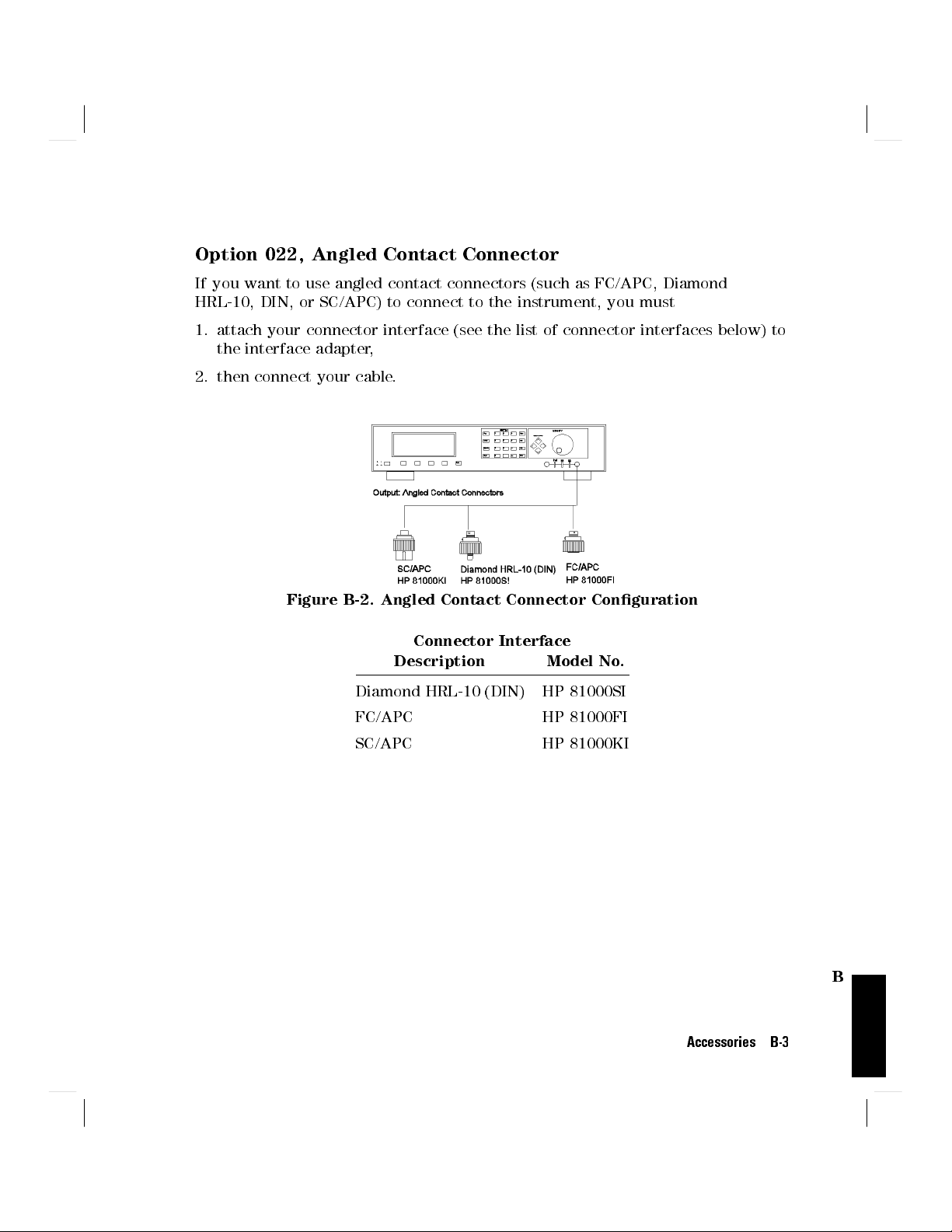
Option 022, Angled Contact Connector
If you want to use angled contact connectors (such as FC/APC, Diamond
HRL-10, DIN, or SC/APC) to connect to the instrument, you must
1. attach your connector interface (see the list of connector interfaces below) to
the interface adapter,
2. then connect your cable.
Figure B-2. Angled Contact Connector Conguration
Connector Interface
Description Model No.
Diamond HRL-10 (DIN) HP 81000SI
FC/APC HP 81000FI
SC/APC HP 81000KI
B
Accessories B-3

 Loading...