


HP 8163A Lightwave
Multimeter &
HP 8164A Lightwave
Measurement System
User’s Guide

Notices
This document contains proprietary information that is protected
by copyright. All rights are
reserved.
No part of this document may be
photocopied, reproduced, or
translated to another language
without the prior written consent
of Hewlett-Packard GmbH.
Copyright 1999 by:
Hewlett-Packard GmbH
Herrenberger Str. 130
71034 Böblingen
Germany
Subject Matter
The information in this document is subject to change without notice.
Hewlett-Packard makes no warranty of any kind with regard to
this printed material, including,
but not limited to, the implied
warranties of merchantability
and fitness for a particular purpose.
Hewlett-Packard shall not be liable for errors contained herein or
for incidental or consequential
damages in connection with the
furnishing, performance, or use
of this material.
Printing History
New editions are complete revisions of the guide reflecting
alterations in the functionality of
the instrument. Updates are
occasionally made to the guide
between editions. The date on
the title page changes when an
updated guide is published. To
find out the current revision of
the guide, or to purchase an
updated guide, contact your
Hewlett-Packard representative.
Control Serial Number: First
Edition applies directly to all
instruments.
Warranty
ThisHewlett-Packardinstrument
product is warranted against
defects in material and workmanship for a period of one year
from date of shipment. During
the warranty period, HP will, at
its option,eitherrepairorreplace
products that prove to be defective.
For warranty service or repair,
this product must be returned to
a service facility designated by
HP. Buyer shall prepay shipping
charges to HP and HP shall pay
shipping charges to return the
product to Buyer. However,
Buyer shall pay all shipping
charges, duties, and taxes for
products returned to HP from
another country.
HP warrants that its software and
firmware designated by HP for
use with an instrument will execute its programming instructions when properly installed on
that instrument. HP does not
warrant that the operation of the
instrument, software, or
firmwarewill be uninterrupted or
error free.
Limitation of
Warranty
The foregoing warranty shall not
apply to defects resulting from
improper or inadequate maintenance by Buyer, Buyer-supplied
software or interfacing, unauthorized modification or misuse,
operation outside of the environmental specifications for the
product, or improper site preparation or maintenance.
No other warranty is expressed
or implied. Hewlett-Packard specifically disclaims the implied
warranties of Merchantability
and Fitness for a Particular Purpose.
Exclusive Remedies
The remedies provided herein
are Buyer’s sole and exclusive
remedies. Hewlett-Packard shall
not be liable for any direct, indirect, special, incidental, or consequential damages whether
based on contract, tort, or any
other legal theory.
Assistance
Productmaintenance agreements
and other customer assistance
agreements are available for
Hewlett-Packard products. For
any assistance contact your nearest Hewlett-Packard Sales and
Service Office.
Certification
Hewlett-Packard Company certifies that this product met its published specifications at the time
of shipment from the factory.
Hewlett-Packard further certifies
that its calibration measurements
are traceable to the United States
National Institute of Standards
and Technology, NIST (formerly the United States National
Bureau of Standards, NBS) to
the extent allowed by the Institutes’s calibration facility,and to
the calibration facilities of other
International Standards Organization members.
ISO 9001
Certification
Produced to ISO 9001 international quality system standard as
part of our objective of continually increasing customer satisfaction through improved
process control.
08164-91011 E0599
First Edition:
E0599: May1999
Firmware Revision:
1.0
Hewlett-Packard GmbH
Herrenberger Str. 130
71034 Böblingen
Germany

HP 8163A Lightwave Multimeter &
HP 8164A Lightwave Measurement System
User’s Guide

Safety Summary
Safety Considerations
The following general safety precautions must be observed during
all phases of operation, service, and repair of this instrument.
Failure to comply with these precautions or with specific warnings
elsewhere in this manual violates safety standards of design,
manufacture, and intended use of the instrument. Hewlett-Packard
Company assumes no liability for the customer’s failure to comply
with these requirements.
General This is a Safety Class 1 instrument (provided with
terminal for protective earthing) and has been manufactured and
tested according to international safety standards.
Before operation, you should review the instrument and manual for
safety markings and instructions. You must follow these to ensure
safe operation and to maintain the instrument in safe condition.
Some HP 8164A circuits are powered whenever the instrument is
connected to the AC power source. To disconnect from the line
power,disconnect the power cord either at the rear power inlet or at
the AC line power source (receptacle). One of these must always be
accessible. If the instrument is in a cabinet, it must be disconnected
from the line power by the system’s line power switch.
WARNING To avoid hazardous electrical shock, do not perform electrical tests
when there are signs of shipping damage to any portion of the outer
enclosure (covers, panels, and so on).
Line Power Requirements
The HP 8163A Lightwave Multimeter can operate from the singlephase AC power source that supplies between 100 V and 240 V at a
frequency in the range 50 to 60 Hz. The maximum power
consumption is 120 VA with all options installed.
4

Safety Summary
The HP 8164A Lightwave Measurement System can operate from
any single-phase AC power source that supplies between 100 V and
240 V at a frequency in the range from 50 to 60 Hz. The maximum
power consumption is 270 VA with all options installed.
Line Power Cable
In accordance with international safety standards, the instrument
has a three-wire power cable. When connected to an appropriate
AC power receptacle, this cable earths the instrument cabinet. The
type of power cable shipped with each instrument depends on the
country of destination. Please refer to the figure below for the part
numbers of available power cables.
WARNING To avoid the possibility of injury or death, you must observe the
following precautions before switching on the instrument.
• If this instrument is to be energized via an autotransformer for
voltage reduction, ensure that the Common terminal connects to the
earth pole of the power source.
• Insert the power cable plug only into a socket outlet provided with a
protective earth contact. Do not negate this protective action by the
using an extension cord without a protective conductor.
5

Safety Summary
• Beforeswitching on the instrument, the protective earth terminal of
the instrument must be connected to a protectiveconductor. You can
do this by using the power cord supplied with the instrument.
• Do not interrupt the protective earth connection intentionally.
The following work must be carried out by a qualified electrician.
All local electrical codes must be strictly observed. If the plug on
the cable does not fit the power outlet, or if the cable is to be
attached to a terminal block, cut the cable at the plug end and rewire
it.
The color coding used in the cable depends on the cable supplied. If
you are connecting a new plug, it should meet the local safety
requirements and include the following features:
• Adequate load-carrying capacity (see table of specifications).
• Ground connection.
• Cable clamp.
Operating Environment
WARNING The HP 8163A Lightwave Multimeter & HP 8164A Lightwave
Measurement System is not designed for outdoor use. To prevent
potential fire or shock hazard, do not expose the instrument to rain or
other excessive moisture.
Input/Output Signals
CAUTION There are two input BNC connectors: the Remote Interlock Connector and
the Trigger Input, see page 152. These are TTL inputs. A maximum of 5 V
can be applied as an external voltage to either of these input connectors.
There is one output BNC connector: the Trigger Output, see page 152. This
is a TTL output. Do not apply an external voltage to this connector.
6

Safety Summary
Additional safety requirements
Operation - Before applying power Comply with the installation
section. Additionally, the following shall be observed:
• Do not remove instrument covers when operating.
• Before the instrument is switched on, all protective earth
terminals, extension cords, auto-transformers and devices
connected to it should be connected to a protective earth via a
ground socket. Any interruption of the protective earth
grounding will cause a potential shock hazard that could result
in serious personal injury.
• Whenever it is likely that the protection has been impaired, the
instrument must be made inoperative and be secured against any
unintended operation.
• There is no user-replaceable fuse in this instrument. The use of
repaired fuses and the short-circuiting of fuseholders must be
avoided.
• Adjustments described in the manual are performed with power
supplied to the instrument while protective covers are removed.
Be aware that energy at many points may, if contacted, result in
personal injury.
• Any adjustments, maintenance, and repair of the opened
instrument under voltageshould be avoidedas much as possible,
and when unavoidable, should be carried out only by a skilled
person who is aware of the hazard involved. Do not attempt
internal service or adjustment unless another person, capable of
rendering first aid and resuscitation is present. Do not replace
components with power cable connected.
• Do not operate the instrument in the presence of flammable
gases or fumes. Operation of any electrical instrument in such an
environment constitutes a definite safety hazard.
• Do not install substitute parts or perform any unauthorized
modification to the instrument.
• Be aware that capacitors inside the instrument may still be
charged even if the instrument has been disconnected from its
source of supply.
7

Safety Summary
Safety Symbols
The apparatus will be marked with this symbol when it is necessary
for the user to refer to the instruction manual in order to protect the
apparatus against damage.
Caution, risk of electric shock.
Frame or chassis terminal.
Protective conductor terminal.
Hazardous laser radiation.
WARNING TheWARNINGsign denotes a hazard. It callsattention to a procedure,
practice or the like, which, if not correctly performed or adhered to,
could result in injury or loss of life. Do not proceed beyond a
WARNING sign until theindicated conditions are fully understood and
met.
CAUTION The CAUTION sign denotes a hazard. It calls attention to an operating
procedure, practice or the like, which, if not correctly performed or adhered
to, could result in damage to or destruction of part or all of the equipment.
Do not proceed beyond a CAUTION sign until the indicated conditions are
fully understood and met.
8

Safety Summary
Initial Safety Information for Tunable Laser Source Modules
HP 81680A HP 81682A HP 81640A HP 81689A
Laser Type Fabry
Perot-Laser
InGaAsP
Laser Class
According to 21
CFR 1040.10 (USA)
Permissible Output Power (CW) <20 mW <20 mW <20 mW <20 mW
Beam Diameter 9 µm9µm9µm9µm
Numerical Aperture 0.1 0.1 0.1 0.1
Wavelength 1200-1670 nm 1200-1670 nm 1200-1670 nm 1200-1670 nm
Laser Class
According to
IEC 825-1 (Non-USA)
EN 60825-1 Europe
Permissible Output Power (CW) <20 mW <20 mW <20 mW <20 mW
Beam Diameter 9 µm9µm9µm9µm
Numerical Aperture 0.1 0.1 0.1 0.1
Wavelength 1400-1670 nm 1400-1670 nm 1400-1670 nm 1400-1670 nm
IIIb IIIb IIIb IIIb
3A 3A 3A 3A
Fabry
Perot-Laser
InGaAsP
Fabry
Perot-Laser
InGaAsP
Fabry
Perot-Laser
InGaAsP
9

NOTE
Safety Summary
.
USA (All Tunable Laser Source Modules HP 81640A/80A/82A/89A)
These laser safety warning labels are fixed on the outsideof the HP 8164A
Lightwave Measurement System before shipment.
10

Safety Summary
Non-USA (All Tunable Laser Source Modules HP 81640A/80A/82A/89A)
These laser safety warning labels are fixed on the outside of the HP 8164A
Lightwave Measurement System before shipment.
A sheet of laser safety warningsis included with the lasermodule. You
MUST stick the labels in the local language onto the outside of the
instrument, in a position where they are clearly visible to anyone using
the instrument.
You MUST return instruments with malfunctioning laser boxes to
an HP Service Center for repair and calibration.
The laser module has a built in safety circuitry which will disable
the optical output in the case of a fault condition.
11

Safety Summary
WARNING Use of controls or adjustments or performance of procedures other
than those specified for the laser source may result in hazardous
radiation exposure.
WARNING Refer Servicing only to qualified and authorized personnel.
WARNING Do not enable the laser when there is no fiber attached to the optical
output connector.
Tunable Laser SourceModules and Laser Source Modules have optical
output connectors.
The laser is enabled by pressing the gray button beside the optical
output connector on the front panel of the module. The laser is enabled
when the green LED on the front panel of the instrument is lit.
WARNING Under no circumstances look into the end of an optical cable attached
to the optical output when the device is operational.
The laser radiation can seriously damage your eyesight.
WARNING The use of optical instruments with this product will increase eye
hazard.
12

Safety Summary
13

Safety Summary
The Structure of this Manual
This manual is divided into 3 categories:
• Getting Started
This section gives an introduction to the instrument. and aims to
make the instrument familiar to you: Chapters 1 and 2.
• How to Use Modules
This is the information on how to control modules from the front
panel: Chapters 3, 4, and 5.
• Additional Information
This is supporting information of a non-operational nature. this
contains installation information, accessories, specifications,
function tests, and cleaning procedures: Appendixes A to E.
Conventions used in this manual
• Hardkeys are indicated by small capitals, for example, CONFIG,
or CHANNEL.
• Softkeys are indicated by normal text enclosed in square
brackets, for example, [Zoom] or [Cancel].
• Parameters are indicated by small capitals enclosed by square
brackets, for example, [RANGE MODE], or [MINMAX MODE].
• Menu items are indicated by small capitals enclosed in brackets,
for example, <MINMAX>, or <CONTINUOUS>.
14

Table of Contents
Safety Considerations ......................................................... 4
Line Power Requirements 4
Line Power Cable 5
Operating Environment 6
Input/Output Signals 6
Additional safety requirements ...........................................7
Initial Safety Information for Tunable Laser Source Modules 9
1 Getting Started
1.1 The HP 8163A Lightwave Multimeter ..................27
1.2 The HP 8164A Lightwave Measurement System .28
1.3 A Description of the User Interface .......................30
Password ............................................................................. 31
If You Forget Your Password 31
User Interface Features ....................................................... 32
Introducing Softkeys 32
Introducing Hardkeys 32
Special Module States 32
Slot and Channel Numbers 32
How to Navigate/Modify the Display ................................ 33
Overview Screen 33
How to Use the Cursor Key 34
How to Use the Numerical Keypad 35
How to Use the Modify Knob 35
How to Change Channel 36
How to Access the Details Screen 36
How to Access the Menu 38
How to Change the System Configuration 39
15

Table of Contents
1.4 How to Change the Value of a Parameter ........... 41
How to Select a Parameter ..................................................42
How to Accept the New Value of a Parameter ...................42
How to Make a Big Change to a Continuous Parameter .....42
How to Make a Small Change to a Continuous Parameter 43
How to Change a Discrete Parameter .................................44
How to Set All Parameters to Their Default Values ...........45
If You Make a Mistake ........................................................45
If the Parameter Changes to Different Value ......................45
1.5 A Sample Session .................................................... 46
How to Measure the Power of a Modulated Signal ............46
2 Additional Features
2.1 Using the System Utilities ...................................... 51
How to Set the Backlight & Contrast ..................................52
To Set the Contrast 52
How to Set the HP-IB Address ...........................................53
How to Lock/Unlock the Instrument ...................................54
How to Change the Password ..............................................56
If You Forget Your Password .............................................56
How to Set the Trigger Configuration .................................56
How to Get Information About Modules ............................57
How to Get Information About the Mainframe ..................58
2.2 How to Connect an External Monitor .................. 59
16

Table of Contents
3 Power Measurement
3.1 How to Measure Power ..........................................63
The Power Value ................................................................ 63
How to Set the Number of Digits 63
How to Set the Power Unit ................................................. 64
What are the Power Units ? 64
How to Set the Calibration Offset ...................................... 66
How to Set the Reference Level ......................................... 67
How to Input a Reference Level 67
Howto Set the ReferenceValue to the Current Power
Value 68
How to Reference Another Power Measurement
Channel 68
How to Set the Wavelength ................................................ 70
How to Remove Electrical Offsets ..................................... 70
How to Choose the Range Mode ........................................ 73
How to Set the Range ......................................................... 74
Upper Power Limit and Resolution 80
How to Set the Averaging Time ......................................... 80
How to Choose the MinMax Mode .................................... 81
How to Turn Off MinMax Mode ........................................84
How to Hold the Screen ...................................................... 85
4 Laser Sources
4.1 How to Use Laser Source Modules ........................89
The Laser Wavelength Value ............................................. 89
Dual-Wavelength Laser Source Modules 90
17

Table of Contents
How to Enable/Disable Laser Output ..................................90
How to Set Attenuation .......................................................91
How to Modulate the Optical Output ..................................92
How to Change Modulation Source 92
How to Modulate the Output Signal 93
5 Tunable Lasers
5.1 What is a Tunable Laser ? .................................... 97
5.2 How to Set the Power ............................................. 97
How to Set the Output Power of a CW Signal ....................98
How to Set Output Power 98
How to Set the Optical Output 98
How to Set the Optical Output 101
How to Enable the Optical Output 101
How to Set Power and Attenuation 102
What is Excessive Power ? ..................................................104
The Analog Output ..............................................................105
How to Set the BNC Output Line Mode as an Analog
Output 106
5.3 How to Set the Wavelength ................................... 106
Wavelength Range ..............................................................106
How to Set the Wavelength Directly ...................................107
How to Set a Relative Wavelength .....................................107
How to Change the Output Wavelength 108
How to Set the Base Wavelength 109
How to Change the Frequency Offset 109
5.4 How to Perform a Wavelength Sweep ................. 109
18

Table of Contents
What is a Wavelength Sweep ? .......................................... 109
How to Set the Wavelength Sweep .................................... 110
The Sweep Parameters 110
How to Set the Repeat Mode 110
How to Set the Maximum Power for the Sweep
Range 111
How to Perform a Sweep .................................................... 111
How to Execute a Stepped Sweep 112
How to Execute a Continuous Sweep 114
How to Perform a Manual Sweep 115
5.5 How to Modulate a Signal ......................................116
How to Use the Internal Modulation .................................. 117
How to Set the Output Power of a Modulated Signal
117
How to Set theFrequency ofa ModulatedSignal 117
How to Set the Modulation Mode 117
How to Use External Modulation ....................................... 118
External Digital Modulation 118
External Analog Modulation 119
Wavelength Locking 120
External Digital Modulation using Input Trigger
Connector 121
How to Increase Linewidth 122
How to Set the Output Power of a Modulated Signal
123
How to Configure the Modulation Output ......................... 123
How to Set the BNC Output Line Mode as a Modulation Output 123
How to Set the Modulation Output Mode 123
5.6 How to Use Triggers ...............................................124
How to Use Input Triggering .............................................. 124
How to Use Output Triggering ........................................... 125
19

Table of Contents
5.7 How to Use Auxiliary Functions ........................... 127
Automatic Realignment .......................................................127
How to Perform a Wavelength Zero ...................................128
A Installation and Maintenance
A.1 Safety Considerations ........................................... 133
A.2 Initial Inspection ................................................... 133
A.3 AC Line Power Supply Requirements ................ 134
Line Power Cable ................................................................134
Changing the Battery ...........................................................137
Changing the Fuse ...............................................................138
A.4 Operating and Storage Environment .................. 138
Temperature ........................................................................139
Humidity ..............................................................................139
Storage and Shipment ..........................................................139
Instrument Cooling ..............................................................139
Operating Position 140
Storage Position ...................................................................141
Carrying the Instrument ......................................................142
A.5 Using Modules ....................................................... 143
How to Fit and Remove Modules .......................................143
How to Remove a Front-Loadable Module 144
How to Fit a Front-Loadable Module 145
How to Remove a Back-Loadable Module 146
How to Fit a Back-Loadable Module 148
Adding a Connector Interface .............................................149
Protecting Empty Module Slots ..........................................150
20

Table of Contents
Fitting Blind Panels for Front-Loadable Module
Slots 150
Fitting a Filler Module for Back-Loadable Module
Slots 151
A.6 Input and Output Connectors ...............................152
A.7 HP-IB Interface ......................................................153
Cables and Adapters ........................................................... 154
Connector ............................................................................ 154
A.8 HP-IB Logic Levels ................................................155
A.9 Claims and Repackaging .......................................156
Return Shipments to HP ..................................................... 156
Hewlett-Packard Sales and Service Offices ....................... 157
United States 157
Canada 157
Europe 157
Japan 157
Latin America 158
Australia/New Zealand 158
Asia Pacific 158
B Accessories
B.1 Instrument and Options - HP 8163A ....................161
Modules .............................................................................. 161
User’s Guides ..................................................................... 161
B.2 Instrument and Options - HP 8164A ....................162
Modules .............................................................................. 162
HP 81645A Filler Module .................................................. 162
21

Table of Contents
Options ................................................................................163
Option 003 - HP 81682A 163
Option 021 - HP 81689A 163
Option 022 - HP 81689A 163
Option 071 - All Tunable Laser Source Modules 163
Option 072 - All Tunable Laser Source Modules 163
User’s Guides ......................................................................164
B.3 HP 8153A Lightwave Multimeter Modules ........ 164
B.4 HP-IB Cables and Adapters ................................. 166
C Specifications
C.1 HP 8163A Specifications ...................................... 169
C.2 HP 8164A Specifications. ..................................... 170
C.3 Declaration of Conformity .................................. 172
HP 8163A Lightwave Multimeter .......................................172
Supplementary Information .................................................172
HP 8164A Lightwave Measurement System ......................173
Supplementary Information .................................................174
D Performance Tests
Equipment Required ............................................................177
Test Record .........................................................................177
Test Failure ..........................................................................178
Instruments Specifications ..................................................178
22

Table of Contents
D.1 Performance Test Instructions .............................179
Display/Key Functional Test .............................................. 179
Testing Hardkeys 179
Testing the Softkeys and the Cursor Key 180
Testing the Softkeys and the Enter Key 180
Testing the the Modify Knob 181
Testing the Number Keys 182
Module Interaction Test ...................................................... 182
Test of the Tunable Laser Module Channel (Slot 0)
183
HP-IB Interface Test (Optional) ......................................... 184
D.2 Test Record .............................................................185
E Cleaning Procedures
E.1 Cleaning Materials ................................................195
E.2 Cleaning Instrument Housing ..............................195
E.3 Cleaning Fiber/Panel Connectors ........................196
E.4 Cleaning Connector Interfaces ............................196
E.5 Cleaning Connector Bushings ..............................197
E.6 Cleaning Detector Windows .................................197
E.7 Cleaning Lens Adapters ........................................197
E.8 Cleaning Detector Lens Interfaces .......................198
F Firmware Updates
23

Table of Contents
F.1 Firmware Update Process ..................................... 201
How to Get a Firmware Update ..........................................201
Download Firmware Update from Internet 201
Firmware Update Request Card 201
How to Update Firmware ....................................................203
How to Update Firmware from the Internet 203
How to Update Firmware from CD-ROM 203
How to Update Firmware from Floppy Disk 203
24

1
1 Getting Started

Getting Started
This chapter introduces the features of the HP 8163A Lightwave
Multimeter and the HP 8164A Lightwave Measurement System.
Here you will find a quick description of the instrument, how to use
the user interface and how to perform a simple sample session.
26

Getting Started
The HP 8163A Lightwave Multimeter
This chapter introduces the features of the HP 8163A Lightwave
Multimeter and the HP 8164A Lightwave Measurement System
and gives you the opportunity to learn how to operate the
instrument.
The central element of the instrument is the HP 8163A Lightwave
Multimeter and the HP 8164A Lightwave Measurement System
mainframes. You customize the instrument using plug-in modules
and changeable fiber-connector interfaces. You can use this
instrument as a tunable laser source and also to take associated
measurements.
1.1 The HP 8163A Lightwave Multimeter
Figure 1-1 The HP 8163A Lightwave Multimeter Mainframe
The HP 8163A Lightwave Multimeter is a high-performance
optical multimeter for the characterization and evaluation of optical
components.
It’s modular format makes it flexible enough to meet changing
needs when measuring optical power, power loss, or return loss for
single or multi-mode components.
27

Getting Started
The HP 8164A Lightwave Measurement System
The HP 8163A Lightwave Multimeter mainframe has two slim
module slots. The system can host up to two front-loadable
modules, of any combination of the following types:
• the HP 81689A Tunable Laser,
• Power Sensors,
• fixed wavelength Laser Sources, and
• Interface Modules for Optical Heads.
The front-loadable module slots support all modules designed for
the HP 8153A Lightwave Multimeter except the HP 81534A
Return Loss Module, which may be supported by later firmware
releases.
1.2 The HP 8164A Lightwave Measurement
System
Figure 1-2 The HP 8164A Lightwave Measurement System Mainframe
The HP 8164A Lightwave Measurement System mainframe has
one large and four slim module slots.
28

Getting Started
The HP 8164A Lightwave Measurement System
The system can host:
1 one back-loadable Tunable Laser module
2 andup to four front-loadable modules,of any combinationof the
following types:
• HP 81689A Tunable Laser,
• Power Sensors,
• fixed wavelength Laser Sources, and
• Interface Modules for Optical Heads.
The front-loadable module slots support all modules designed for
the HP 8153A Lightwave Multimeter except the HP 81534A
Return Loss Module, which may be supported by later firmware
releases.
29

Getting Started
A Description of the User Interface
1.3 A Description of the User Interface
Figure 1-3 and Figure 1-4 show the user interface of the HP 8164A
and the HP 8163A, respectively, and the names used in this manual
to describe the groups of keys.
Display Key Key
Enter Channel
Cursor Key
Numeric
Power Key Hardkeys Softkeys Keypad
Figure 1-3 The HP 8164A Lightwave Measurement System User Interface
The HP 8163A does not provide the following two features of the
HP 8164A’s user interface:
Modify
Knob
• the Modify Knob, and
• the Numeric Keypad.
30

Getting Started
A Description of the User Interface
Display Cursor Key
Figure 1-4 The HP 8163A Lightwave Multimeter User Interface
Softkeys
Enter ChannelHardkeys
Key Key
Password
Power Key
When you use this instrument with high-power Laser Source
modules or Tunable Laser modules, you must enter the password to
unlock the instrument.
NOTE The default password is
If You Forget Your Password
If you forget your password, contact your nearest Hewlett-Packard
Sales/Service Office.
31
1234
.

Getting Started
A Description of the User Interface
User Interface Features
Introducing Softkeys
A softkey is a key whose function changes depending on the keys
that you have pressed before. The function of the softkey is shown
on the display to the left of the softkey.
Introducing Hardkeys
A hardkey is a key that always has the same function.
Special Module States
Besides parameter or measurement values, you may also see some
texts instead.
<empty> The slot is empty.
<unknown> The installed module is not supported by the
firmware revision.
Slot and Channel Numbers
Each module is identified by a slot number and a channel number.
You can use slot and channel numbers:
• to identify each channel in the overview screen with a number
at the side of the screen,
• to identify each channel in the Details screen with a tab at the
top of the screen, and
• to identify the channel when referencing the power measured
by another channel, see “How to Reference Another Power
Measurement Channel” on page 68, and
• to identify a channel when using a HP-IB command, see the
HP 8163A Lightwave Multimeter & HP 8164A Lightwave
Measurement System Programming Guide for more
information on HP-IB commands.
The slot number represents the module’s position in the mainframe.
Front-loadable modules are numbered from one to two from left to
right for the HP 8163A and from one to four from left to right for
the HP 8164A. These numbers are displayed on the front panel
32

Getting Started
A Description of the User Interface
beside each module slot. The HP 8164A slot for back-loadable
modules is numbered zero.
NOTE The channel number of single channel modules is always one.
How to Navigate/Modify the Display
Overview Screen
Figure 1-6 shows the overview screen, this screen is shown
immediately after start-up. It shows the most important parameters
of all installed modules.
Figure 1-5 The HP 8163A’s Overview Screen
33

Getting Started
A Description of the User Interface
Figure 1-6 The HP 8164A’s Overview Screen
How to Use the Cursor Key
Figure 1-7 The Cursor Key
You can move the highlighted marker between parameters using the
[Cursor] hardkey.
34

Getting Started
A Description of the User Interface
When editing a parameter, see “How to Change the Value of a
Parameter” on page 41, the up anddown cursor keys can be used to
increment and decrement the value of a digit and the left and right
cursor keys can be used to move the highlighted digit left and right.
How to Use the Numerical Keypad
NOTE The Numerical Keypad is only available if you use the HP 8164A.
You can use the Numerical Keypad to change the value of a
parameter. See “How to Change the Value of a Parameter” on
page 41.
How to Use the Modify Knob
NOTE The Modify Knob is only available if you use the HP8164A.
Figure 1-8 The Modify Knob
You can use the Modify Knob to navigate around the display. When
you turn the Modify Knob through one click, one action is
performed.
Turning the Modify Knob clockwise moves the highlighted marker
right and then down. Turning the Modify Knob anti-clockwise
moves the highlighted marker left and then up.
You can use the Modify Knob to change the value of a parameter.
See “How to Change the Value of a Parameter” on page 41.
35

Getting Started
A Description of the User Interface
How to Change Channel
You can navigate between module channels by pressing the
CHANNEL hardkey. You can use this key when either the overview
screen or the details screen is displayed.
How to Access the Details Screen
You can access the parameters of a module that are not shown on
the overviewscreen by pressing CHANNEL to select the channel and
pressing the [Details] softkey. You should see the Details screen as
shown in Figure 1-9 or Figure 1-10.
Figure 1-9 The HP 8163A’s Details Screen for a Power Sensor Channel
36

Getting Started
A Description of the User Interface
Figure 1-10 The HP 8164A’s Details Screen for a Tunable Laser Channel
To return to the overview screen press the [Overview] softkey.
37

Getting Started
A Description of the User Interface
How to Access the Menu
Press the [Menu] softkey to access all the parameters of a module
that can be changed. Figure 1-11 and Figure 1-12 show the type of
menu you should see for a Power Sensor channel.
Figure 1-11 The HP 8163A’s Menu for a Power Sensor Channel
38

Getting Started
A Description of the User Interface
Figure 1-12 The HP 8164A’s Menu for a Power Sensor Channel
How to Change the System Configuration
Press the [Config] softkey to access all the system configuration
parameters that can be changed. Figure 1-13 and Figure 1-14 show
the menu you should see. See Chapter 2 “Additional Features” for
more details.
39

Getting Started
A Description of the User Interface
Figure 1-13 The HP 8163A System Configuration Menu
40

Getting Started
How to Change the Value of a Parameter
Figure 1-14 The HP 8164A System Configuration Menu
1.4 How to Change the Value of a Parameter
What follows is a description of the various ways of changing the
valueof parameters. Examples in which particular parameter values
are changed are given with the parameter descriptions.
Parameters can be either:
• continuous, you may choose any value within a given range, or
• discrete, you may choose a value from a menu.
41

Getting Started
How to Change the Value of a Parameter
How to Select a Parameter
You can select the parameter from the following screens:
• from the Overview screen,
• from the Details screen, after pressing the [Details] softkey, or,
• from the Menu screen, after pressing the [Menu] softkey.
To start editing a parameter, you move to it and:
• press the ENTER hardkey,
• press the [Edit] softkey,
• press the Modify Knob (if you are using the HP 8164A), or,
• for numerical parameters only, type a digit on the numerical
keypad (if you are using the HP 8164A).
How to Accept the New Value of a Parameter
When you have changed the value of a parameter, to accept this
change:
• press the ENTER hardkey,
• press the [OK] softkey,
• or, press the Modify Knob (if you are using the HP 8164A).
These keys all perform the same purpose. All references to pressing
ENTER throughout this User’s Guide, refer to one of these three
actions.
How to Make a Big Change to a Continuous Parameter
If you are changing the value of a parameter completely,type in the
value on the keypad (if you are using the HP 8164A), and press
ENTER.
To change the output power from 100 µW to 755 µW:
1 Press the [Menu] softkey.
2 Move to Power, using the cursor key, and press ENTER.
3 Type 755.000 on the numeric keypad and press ENTER.
42

Getting Started
How to Change the Value of a Parameter
How to Make a Small Change to a Continuous Parameter
For small changes to a parameter use the up and down cursor keys,
the numerical keypad (if you are using the HP 8164A), or the
modify knob (if you are using the HP 8164A).
Move to the parameter and then:
1 Press [Edit]. The first digit before the decimal point will be
highlighted first, as shown in Figure 1-15.
Figure 1-15 The First Digit Before the Decimal Point is Highlighted First
2 If you want to select another digit to edit, use the left or right
cursor key.
3 Enter the new value for the digit by using the keypad, the up and
down cursors or turning the modify knob.
4 Repeat steps 2 and 3 to continue editing the value.
43

Getting Started
How to Change the Value of a Parameter
5 When you have finished editing the value, press ENTER. The
edited value becomes the new value of the parameter.
To change the wavelength from 1540.000 nm to 1525.000 nm:
1 Move to the wavelength parameter for a Tunable Laser module
and press [Edit]. The most significant digit is highlighted.
2 Press the left cursor once to highlight the digit four.
3 Press the down cursor twice to change the value of the digit to
two.
4 Press the right cursor once to move the cursor one digit right.
5 Press the up cursor five times to change the value of the digit to
five. Press ENTER to end the editing.
How to Change a Discrete Parameter
For discrete parameters, you may choose a particular values within
a given range.
For a Power Sensor module:
1 Move to the Power Sensor channel and press the [Details]
softkey.
2 Move to the [AVGTIME] parameter and press ENTER.
3 Move to 1 s, by using the cursor key, and press ENTER.
or
1 Moveto the Power Sensor channel and press the [Menu] softkey.
2 Move to the <AVERAGING TIME> parameter and press ENTER.
You see the screen in Figure 1-16.
3 Move to <1 s>, by using the cursor key, and press ENTER.
44

Getting Started
How to Change the Value of a Parameter
Figure 1-16 Averaging Time Menu
How to Set All Parameters to Their Default Values
Press PRESET to set all parameters to their default values.
If You Make a Mistake
If you make a mistake while you are editing a parameter, you can
cancel the editing, and retain the previous value for the parameter
by pressing the [Cancel] softkey.
If the Parameter Changes to Different Value
If you press ENTER or the [OK] softkey and the parameter changes
to a different value, then you tried to enter a value outside the
calibrated range. The new value is the nearest valid value to the
value you entered.
45

Getting Started
A Sample Session
1.5 A Sample Session
This sample session shows you how to measure the power of a
modulated signal at a single wavelength.
The sample session is written for the HP 8163A Lightwave
Multimeter or HP 8164A Lightwave Measurement System, the
HP 81689A Tunable Laser module, and the HP 81532A Power
Sensor. To perform the sample session as described here, you also
need a patchcord (if you are using the 81000AI Connector
interface, then a Diamond HMS-10/HP/HRL to Diamond HMS-10/
HP patchcord, HP 81109AC).
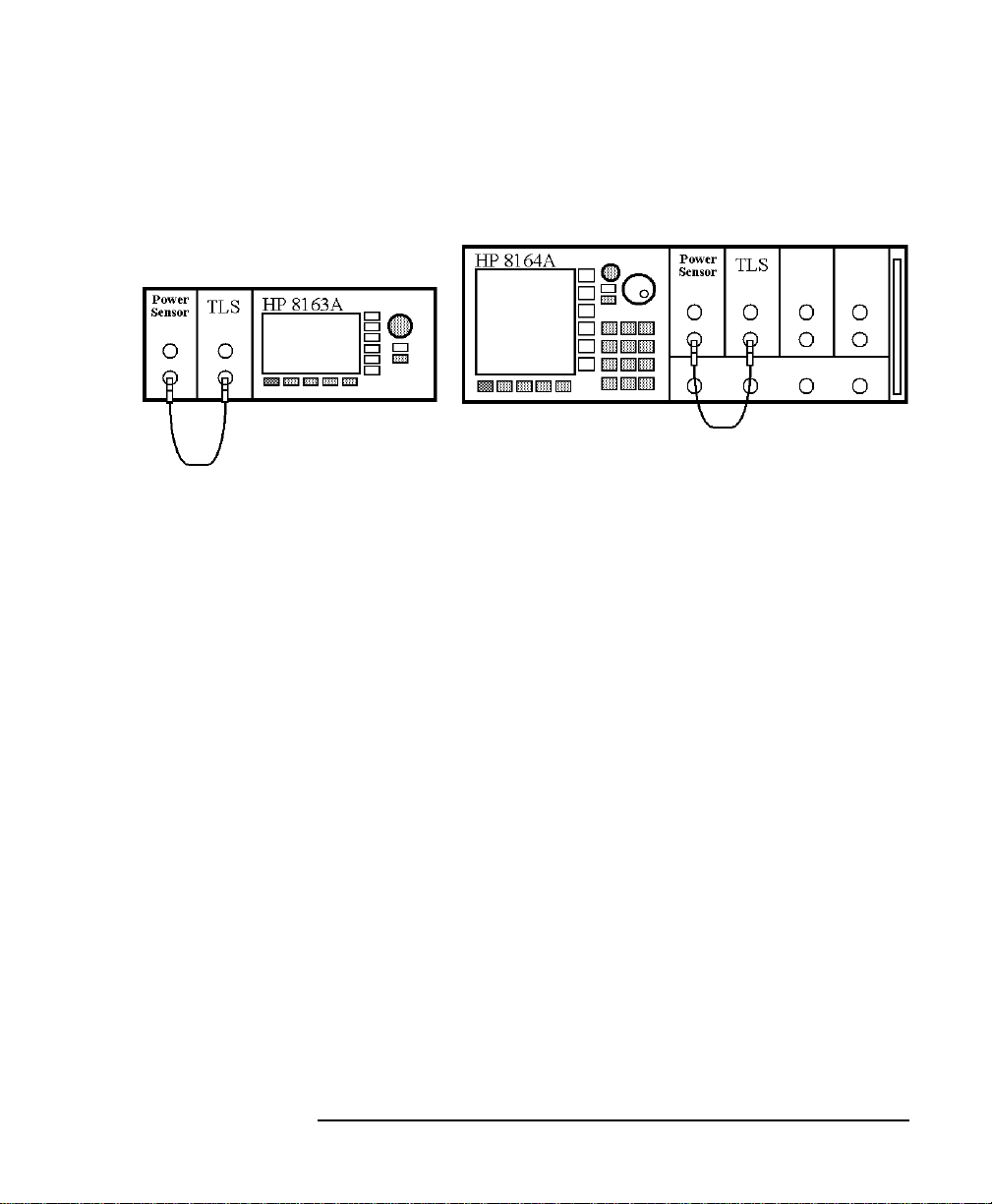
How to Measure the Power of a Modulated Signal
We want to measure the power of a 1540 nmsignal, modulated by a
100 kHz square wave, at 500 µW.
1 Make sure that all your connectors, and connector interfaces are
clean.
2 Make sure that the Optical Output of the Laser Source is not
active.
3 Connect the output of the Laser Source to the input of the Power
Sensor module, as shown in Figure 1-17. You must connect the
correct fiber end connector for your Tunable Laser module:
a For straight contact connectors, use a straight contact fiber
end connector with a black sleeve.
b For angled contact connectors with a green sign beside the
Tunable Laser module’s optical output connector, use an
angled contact fiber end connector with a green sleeve.
46
Getting Started
A Sample Session
Figure 1-17 Connecting the Instrument for the Sample Session
4 Make sure the instrument is powered up.
5 How to set the wavelength for the Power Sensor module:
a Move to the wavelength parameter, [λ], for the Power
Sensor module and press ENTER.
b Enter 1540.000 and press ENTER.
6 How to set the averaging time for the Power Sensor module:
a Move to the measurement averaging time, [TAVG], and
press ENTER.
b Move to <1 s>, using the cursor key, and press ENTER.
7 For the Power Sensor module, make sure that Watts are the
selected Power Unit and that the instrument is in automatic
ranging mode. To change these settings:
a Move to the power parameter, [P], and press the
[Power Unit] softkey.
b Move to <W>, using the cursor key, and press ENTER.
c Move to the [RANGE MODE] parameter and press ENTER.
d Move to <AUTO>, using the cursor key, and press ENTER.
47

Getting Started
A Sample Session
8 How to set the wavelength for the Tunable Laser module:
a Move to the wavelength parameter, [λ], for the Tunable
Laser module and press ENTER.
b Enter 1540.000 and press ENTER.
9 How to set the modulated power for the Tunable Laser module:
a If power is not displayed in Watts, move to the [POWER]
parameter and press the [Power Unit] softkey.
b Move to <W>, using the cursor key, and press ENTER.
c Move to the [POWER] parameter and press ENTER.
d Enter 500.000.
e Change units to µW, if necessary, using the [Unit+] or
[Unit−] softkey.
f Press ENTER.
10 How to set the modulation frequency for the Tunable Laser
module:
a Select the [FREQUENCY] parameter and press ENTER.
b Change units to kHz, if necessary, using the [Unit+] or
[Unit−] softkey.
c Enter 100.000 and press ENTER.
11 For the Tunable Laser module, press the button beside the
Optical Output. The green LED should switch on to indicate that
the laser is now active.
You should notice that the power reading is approximately half the
value set on the TunableLaser module. This is because the output is
modulated by a square wave with a 50% duty cycle.
48

2
2 Additional Features

Additional Features
This chapter introduces addditional features of the HP 8163A
Lightwave Multimeter and the HP 8164A Lightwave Measurement
System. Here you will find out how to set the configuration settings
and how to connect an external monitor.
50

Other Functions
Using the System Utilities
This describes how to use the system functions of the HP 8163A
Lightwave Measurement System and the HP 8164A Lightwave
Measurement System.
2.1 Using the System Utilities
Press the CONFIG hardkey to access configuration information for
your mainframe. You see the screens in Figure 2-1 and Figure 2-2.
Figure 2-1 The HP 8163A System Configuration Menu
51

Other Functions
Using the System Utilities
Figure 2-2 The HP 8164A System Configuration Menu
You can move to any of the menu items by using the cursor key or
the Modify knob. Select an item by pressing ENTER or the [OK]
softkey.
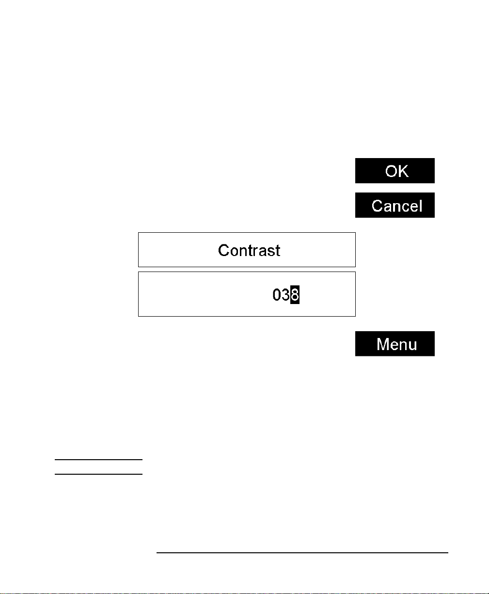
How to Set the Backlight & Contrast
TheContrast menu option allows you to set the appearance of the
screen.
NOTE The Contrast menu option is supported by the HP 8163A but not the
HP 8164A.
To Set the Contrast
To change the contrast level of the HP 8163A’s screen:
52
Other Functions
Using the System Utilities
1 Press the CONFIG hardkey.
2 Move to the <CONTRAST> menu option and press ENTER. You
see a box displaying the current setting.
Figure 2-3 Entering a Contrast Value
3 Enter an integer value between zero and one hundred in this box
and press ENTER.
How to Set the HP-IB Address
NOTE The default HP-IB address is 20.
To set the HP-IB address:
1 Press the CONFIG hardkey.
2 Move to the <HP-IB ADDRESS> menu option and press ENTER.
53

Other Functions
Using the System Utilities
You see a box displaying the current HP-IB address.
Figure 2-4 Entering a HP-IB Address
3 Enter an integer value between 0 and 30 into this box and press
[Enter]. The address is set to this value.
How to Lock/Unlock the Instrument
To unlock the instrument:
1 Press the CONFIG hardkey.
2 Move to the <UNLOCK> menuoption and press ENTER. Yousee
a box requesting you to enter the password.
54

Other Functions
Using the System Utilities
Figure 2-5 Unlocking the Instrument
3 Enter the password, using the softkeys or the numerical keypad.
Press ENTER and the instrument unlocks.
NOTE The default password is
To lock the instrument, perform the steps above, but in step 2 move
to the <LOCK> menu option in place of the <UNLOCK> menu
option.
55
1234
.

Other Functions
Using the System Utilities
How to Change the Password
The password is used for unlocking the instrument. To change the
password:
1 Press the CONFIG hardkey.
2 Move to the <CHANGE PASSWORD> menu option and press
ENTER. You see a box requesting you to enter the password.
3 Enter the password, using the softkeys or the numerical keypad
and press ENTER. You are asked to enter the new password.
4 Enter your new password. It should be 4 digits long. Press
ENTER. You are asked to enter the new password again.
5 Enter your new password again and press ENTER.
If You Forget Your Password
If you forget your password, contact your nearest Hewlett-Packard
Sales/Service Office.
How to Set the Trigger Configuration
The trigger level at the external trigger connectors is by default
active high, this means when a trigger rises above the high TTL
level, a trigger is accepted.
You can select three modes of triggering from the trigger
configuration menu:
•<NONE>, which you should choose if you do not want to use
triggering.
•<DEFAULT>, which you should choose if you want to enable
the trigger connectors.
•<PASS THROUGH>, which you should choose if you want an
input trigger to automatically generate an output trigger. This
allows you to trigger another instrument almost simultaneously.
•<LOOPBACK>, which you should choose if you want an output
trigger to automatically generate an input trigger. For example,
using this mode, you could trigger each step of a wavelength
sweep with just one externally generated input trigger.
56

Other Functions
Using the System Utilities
To change the triggering mode:
1 Press the CONFIG hardkey.
2 Move to the <TRIGGER> menu option and press ENTER.You see
a box displaying the available triggering modes.
Figure 2-6 Changing the Triggering Mode
3 Move to your chosen triggering mode and press ENTER.
How to Get Information About Modules
To get information about modules:
1 Press the CONFIG hardkey.
2 Moveto the <ABOUT MODULES> menu option and press ENTER.
You see a box displaying information about the installed
modules, see Figure 2-7. The part number and firmware revision
of each installed module is listed.
57

Other Functions
Using the System Utilities
3 Press <Close> to return to the configuration menu.
Figure 2-7 Viewing Information About Modules
How to Get Information About the Mainframe
To get information about the mainframe:
1 Press the CONFIG hardkey.
2 Move to the <ABOUT MAINFRAME> menu option and press
ENTER.You see a box displaying information about the installed
modules, see Figure 2-8. The part number, development team,
and firmware revision of the mainframe are listed.
58

Other Functions
How to Connect an External Monitor
Figure 2-8 Viewing Information About the Mainframe
3 Press <Close> to return to the configuration menu.
2.2 How to Connect an External Monitor
You can connect a standard VGA monitor to the HP 8164A
Lightwave Measurement System. This is a useful feature for
making presentations or for training courses.
NOTE You cannot connect a monitor to the HP 8163A Lightwave Multimeter.
59

Other Functions
How to Connect an External Monitor
Video Outlet
Figure 2-9 Rear Panel of the HP 8164A Lightwave Measurement System
• Place your monitor on a flat sturdy surface.
• Before you make any connections make sure the Lightwave
Measurement System and monitor are turned off.
• Connect the power cable to the video input on the back of your
monitor. Tighten the thumbscrews on the plug.
• Connect the video cable (it has a 15-pin plug) to the video
outlet on the back of the Lightwave Measurement System.
Tighten the thumbscrews on the plug.
• Connect the power cord to the display.
• Plug the power cord into the power outlet.
NOTE Refer to the user’s guide that came with your monitor, if necessary, to
locate your monitor’s output and input ports.
60

3
3 Power Measurement

Power Measurement
This chapter explains how to measure optical power from the user
interface of the HP 8163A Lightwave Multimeter and the
HP 8164A Lightwave Measurement System.
You may measure power using a Power Meter, that is:
• a Power Sensor module or
• an Optical Head in conjunction with an Optical Head Interface
module.
62

Power Measurement
How to Measure Power
This chapter describes how to use the HP 8163A Lightwave
Multimeter and the HP 8164A Lightwave Measurement System to
measure optical power.
3.1 How to Measure Power
The Power Value
The <P> parameter displays the power measurement value. In
MinMax mode, this parameter changes to <∆P>, the difference
between minimum and maximum power, see page 81.
How to Set the Number of Digits
You can set the number of digits that are used in power
measurement. These are the number of digits after the decimal
point. To change the number of digits to two:
1 Move to the Power Meter channel and press the [Menu] softkey.
2 Move to <NUMBER OF DIGITS> option and press ENTER. You
will see the screen in Figure 3-1.
63

Power Measurement
How to Measure Power
Figure 3-1 The Number of Digits Menu
3 Move to 2 and press ENTER.
4 Press the [Close] softkey to exit the menu.
How to Set the Power Unit
Pressing the Power Unit softkey allows you to select either W, dB,
or dBm as the units in which power is displayed. The Power Unit
softkey is visible when you move to the P or Ref parameters.
alternatively the Power Unit can be changed by using the Power
Meter menu.
What are the Power Units ?
Watts (W) are the SI unit for power measurement.
64

Power Measurement
How to Measure Power
You can also measure power in dB or dBm. Values displayed in
these units are derived from measurement in Watts.
By selecting dBm, the following calculation is made:
P
dBm
10
P
------------------------------ -log=
110
input
W()
3–
W()×
Where,
P
P
dBm
input
is the power value displayed in dBm, and
is the input signal level in Watts.
Power, in units of dBm, is measured relative to 1 mW, it is an
absolute power measurement.
By selecting dB, the following calculation is made:
10
-------------------------log=
P
input
ref
W()
P
dB
W()
P
Where,
P
P
P
dB
input
ref
is the power value displayed in dB,
is the input signal level in Watts, and
is the chosen reference power value in Watts.
Power, in units of dB, is measured relative to a particular reference
power value. You must select this reference value.
To set the power unit to dBm:
1 Move to the [P] parameter and press the [Power Unit] softkey.
You will see the menu in Figure 3-2.
65

Power Measurement
How to Measure Power
Figure 3-2 Selecting the Power Unit
2 Move to <dBm>, by using the cursor key, and press ENTER.
How to Set the Calibration Offset
This is a calibration offset that you can enter to compensate for
external optical circuitry, for example, the HP 81022FF Integrating
Sphere or a 3 dB coupler. The calibration offset, [CAL], is
automatically subtracted from the input signal.
P
measured
Where,
P
measured
66
(dBm) = P
(dBm) − CAL(dB)
input
is the adjusted value of the signal read in dBm,

Power Measurement
How to Measure Power
P
input
is the input signal level , and
CAL is the calibration offset.
To set the calibration offset to 40.000 dB:
1 Move to the Power Meter channel and press the [Details]
softkey.
2 Move to the [CAL] parameter and press ENTER.
3 Enter 40.000 and press ENTER.
How to Set the Reference Level
How to Input a Reference Level
dB results are shown relative to a reference level. The Ref
parameter sets the reference level. Setting, or changing, the
reference only affects results that are displayed in dB.
The reference level is displayed in units of dBm or Watts.
Depending on which is selected the following equations are used to
calculate the power level in dB:
P
display
P
(dB) = P
display
measured
dB() 10
(dBm) − REF(dBm)
or
P
measured
---------------------------------- -log=
REF W()
W()
Where,
P
display
P
measured
is the displayed relative power,
is the absolute power level (see “How to Set the
Calibration Offset” on page 66), and
REF is the reference level.
You can choose the units for the reference using the Power Unit
softkey. If you choose dB, the power value changes to dB and the
displayed reference level changes to dBm.
67

Power Measurement
How to Measure Power
To set the reference level to 10 mW:
1 Move to the Power Meter channel and press the [Details]
softkey.
2 Move to the [REF] parameter and press the [Power Unit] softkey.
3 Move to <W> and press ENTER twice.
4 Change the units to mW using the [Unit+] and [Unit−]softkeys.
5 Enter 10.000 and press ENTER.
How to Set the Reference Value to the Current Power Value
In addition to entering a new reference value, you can change the
reference value to the currently displayed power value by pressing
the [Dsp->Ref] softkey.
Pressing the [Dsp->Ref] softkey takes the input power level and
stores it as the reference. Setting the reference only affects results
displayed in dB.
When you press the [Dsp->Ref] softkey, the absolute power level,
the power value in dBm or Watts, is stored as the reference, that is:
REF = P
measured
Where,
REF is the reference, and
P
measured
is the absolute power level (see “How to Set the
Calibration Offset” on page 66).
The [Dsp->Ref] softkey is displayed if you move to a power
measurement channel.
How to Reference Another Power Measurement Channel
You can use the reference mode to the reference another Power
Meter’s current power level. If you choose this mode, the reference
of the channel continuously updates to the current power value
measured by the other channel.
68

Power Measurement
How to Measure Power
To reference another channel:
1 Move to the Power Meter channel and press the [Details]
softkey.
2 Move to the [REF MODE] parameter and press ENTER.
3 Move to the channel number you want to reference, using the
cursor key, and press Enter. For example, in Figure 3-3, you
could choose 3.1 (for channel 3.1). Refer to “Slot and Channel
Numbers” on page 32 for information on channel numbers.
Figure 3-3 Referencing Another Channel
To return to setting a constant reference level:
1 Move to the Power Meter channel and press the [Details]
softkey.
2 Move to the [REF MODE] parameter and press ENTER.
3 Move to the <VALUE> menu option and press ENTER.
69

Power Measurement
How to Measure Power
How to Set the Wavelength
This is the wavelength value. The responsivity of the Power Meter
varies with wavelength. For accurate power measurement, you need
to input the wavelength of the optical input. To set the wavelength
to 1545.000 nm:
1 Move to the Power Meter channel and press the [Details]
softkey.
2 Move to the [λ] parameter and press ENTER.
3 Enter 1545.000 and press Enter.
How to Remove Electrical Offsets
Optical Power Meters measure optical power by converting optical
power to electrical power, and then measuring electrical power. An
electrical offset is electrical power that is always present, even if
there no optical power is input. If electrical offsets are not removed,
they affect the accuracy of power measurement.
NOTE The environmental conditions and the temperature of the instrument
affect electrical offset. For the best results you must:
• Allow the instrument time to acclimatize (around 24 hours).
• Allow the instrument time to warm up (around 20 minutes).
• Make sure that the optical input is not receiving any light. If you are
using multi-mode fiber-optic cable, you must disconnect the cable
and cover the input to the Power Meter to perform a zero.
It is good practice to zero the instrument beforemaking any important
measurements.
To remove electrical offsets:
1 Make sure the optical input is not receiving any light. If the
instrument has just been switched on, wait until SETTLING is
not displayed for the module channel.
2 Move to the Power Meter channel and press the [Menu] softkey.
70

Power Measurement
How to Measure Power
Figure 3-4 Module Channels that are Settling
3 Move to the <ZERO> option to zero the current power
measurement channel or the <ZERO ALL> option to zero all
power measurement channels.You will see the screen shown in
Figure 3-5, this appears for around 30 seconds while zeroing is
performed.
71

Power Measurement
How to Measure Power
Figure 3-5 Zeroing Screen
NOTE If you see the screen shown in Figure 3-6, the zeroing operation has
failed because the Power Meter received light. The most common
reason for zeroing to fail is if
• a source is connected to the Power Meter’s input connector,
• the fiber connected to the Power Meter’s input connector is
collecting light, or
• the Power Meter receives ambient light because the input
connector is uncovered.
Press ENTER and start again at step 1.
72

Power Measurement
How to Measure Power
4 When the zeroing operation finishes, press the [Close] softkeyto
close the menu.
Figure 3-6 Zeroing Fails, if the Power Meter Receives Input Light.
How to Choose the Range Mode
You can choose either of two ranging modes from the Range mode
menu:
• <Auto>, the auto-ranging mode, ensures that the result has a
displayed value between 9% and 100% of full scale. The
default state is for automatic ranging to be enabled.
• <Manual>, which allows you to set a user-defined range.
73

Power Measurement
How to Measure Power
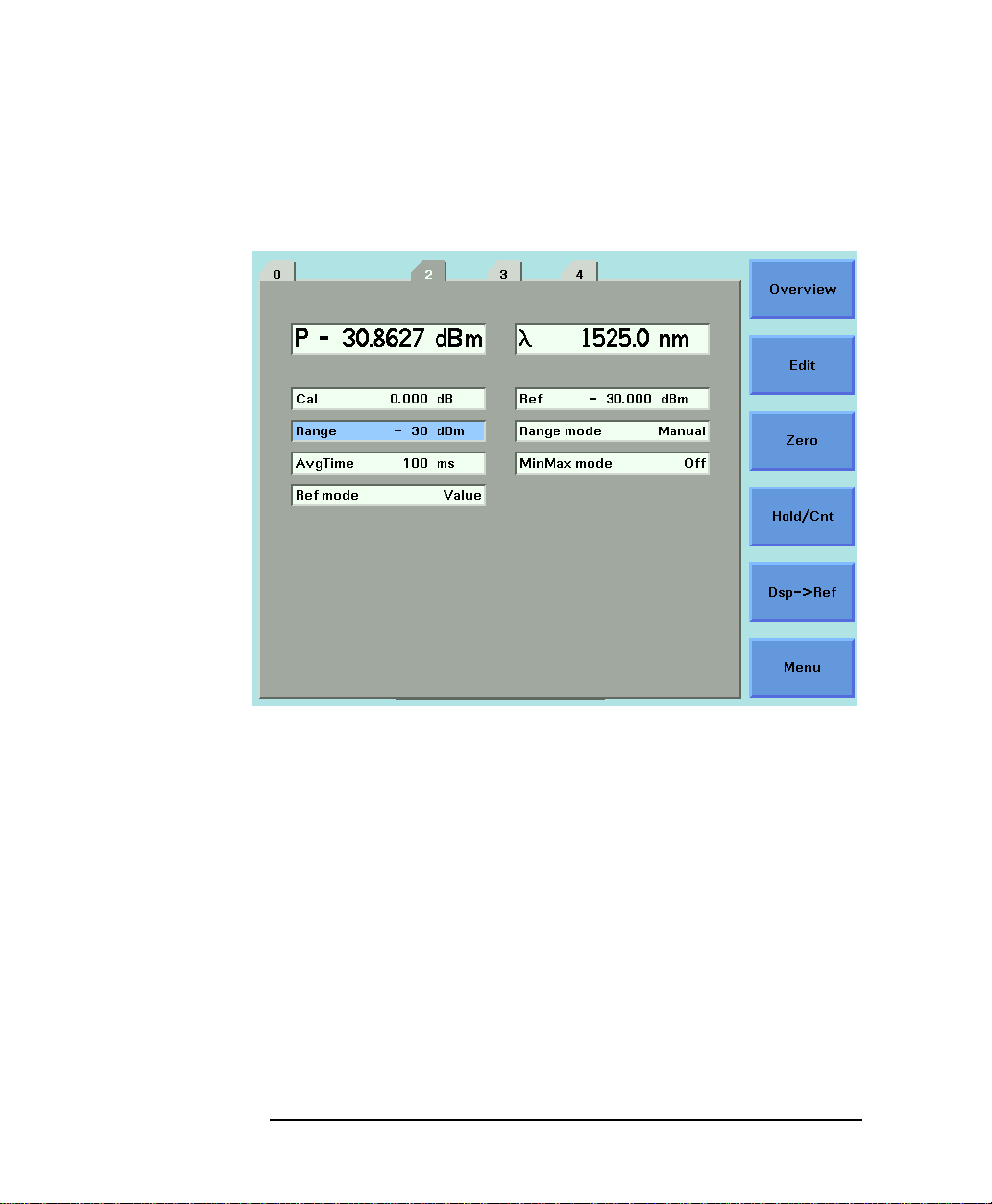
How to Set the Range
If you choose <AUTO> from the Range mode menu, this parameter
can not be set. The Range parameter is displayed in light grey text,
see Figure 3-7, in automatic ranging mode.
Figure 3-7 Auto-Range Mode
If you choose <MANUAL> from the Range mode menu, you must
choose a range setting from the Range menu.
To choose a range setting, follow the following steps:
1 Setup the instrument.
2 Move to the Power Meter channel and press the [Details]
softkey.
3 Move to the [P] parameter and press the [Power Unit] softkey.
You will see the menu in Figure 3-2.
74

Power Measurement
How to Measure Power
4 Move to <dBm>, by using the cursor key, and press ENTER.
5 Move to the [RANGE MODE] parameter and press ENTER.
6 Move to <AUTO>, by using the cursor key, and press ENTER.
7 Perform a set of measurements.
8 Determine the highest power value measured during this set of
measurements
9 Move to the Power Meter channel and press the [Details]
softkey.
10 Move to the [RANGE MODE] parameter and press ENTER.
11 Move to <MANUAL>, by using the cursor key, and press ENTER.
12 Move to the [RANGE] parameter and press ENTER.
13 Move to next highest power value relative to the power value
determined in Step 9, by using the cursor key, and press ENTER.
NOTE If−12 dBm is thehighest power value measured in Step 9, then choose
−10 dBm as the [RANGE] value.
If 8 dBm is the highest power value measured in Step 9, then choose
10 dBm as the [RANGE] value.
75
Power Measurement
How to Measure Power
Figure 3-8 Manual Range Mode - Within Range
76

Power Measurement
How to Measure Power
If the measured power is more than 3dBm greater than the range
setting, it is impossible for power to be displayed. The power value,
+1.--- dBm, as shown in Figure 3-9, is shown. This means that
the measured power is greater than the Upper Power Limit. You
must decrease the [RANGE] value.
See Table 3-1 on page 80 for more details.
Figure 3-9 Out of Range - Power Greater Than Upper Power Limit
77

Power Measurement
How to Measure Power
If the measured power is more than 40 dBm less than the range
setting, it is impossible for power to be displayed. The power value,
-1.--- dBm, asshown in Figure 3-10, is shown. This means that
the measured power is greater than the resolution at this [RANGE]
value. You must increase the [RANGE] value.
See Table 3-1 on page 80 for more details.
Figure 3-10 Out of Range - Power Less Than Resolution
78

Power Measurement
How to Measure Power
Figure 3-11 shows the possiblerange values you can choose. These
values range from 10 dBm (upper power limit of 13 dBm) to
−70 dBm (upper power limit of −67 dBm) in 10 dBm increments.
Figure 3-11 Range Value Menu
79

Power Measurement
How to Measure Power
Upper Power Limit and Resolution
Table 3-1 shows the upper power limit and measurent resolution at
various power ranges. As can be seen the resolution decreases as
the chosen [RANGE] decreases. Resolution is always 40 dBm less
than the chosen [RANGE] value. The Upper Power Limit is always
3 dBm greater than the chosen [Range] value.
[RANGE] Upper Power Limit Resolution
10 dBm 19.999 mW 13.000 dBm 0.001 mW −30.000 dBm
0 dBm 1.9999 mW 3.000 dBm 0.1 µW −40.000 dBm
−10 dBm 199.99 µW −7.000 dBm 0.01 µW −50.000 dBm
−20 dBm 19.999 µW −17.000 dBm 0.001 µW −60.000 dBm
−30 dBm 1.9999 µW −27.000 dBm 0.1 nw −70.000 dBm
−40 dBm 199.99 nW −37.000 dBm 0.01 nw −80.000 dBm
−50 dBm 19.999 nW −47.000 dBm 0.001 nw −90.000 dBm
−60 dBm 1.9999 nW −57.000 dBm 0.1 pW −100.000 dBm
−70 dBm 199.99 pW −67.000 dBm 0.01 pW −110.000 dBm
Table 3-1 Upper Power Limits and Resolution for Various Power Ranges
How to Set the Averaging Time
This is the length of time over which a signal is averaged. Longer
averaging times increase the accuracy and improve the noise
rejection. Longer averaging times also decrease sensitivity.
For averaging times of 1 second or less, a new measurement is
shown at the end of each averaging time. This is drawn in
Figure 3-1. A new measurement is shown on the display at each x.
80

Power Measurement
How to Measure Power
T
avg
xxxxxxxx
Figure 3-1 Measurements with Tavg ≤ 1 second
With modules designed for the HP 8153A Lightwave Multimeter,
for averaging times of more than 1 second, the displayed power is
given by the formula:
T
P
newPold
1
------------------ -–
Where,
sample
T
avg
Sample
+=
T
sample
------------------ -
T
avg
P
new
P
old
is the new displayed result,
is the previously displayed result,
Sample is the value read by the hardware,
T
avg
T
sample
is the averaging time, as set by the user, and
is the time the hardware takes to make a reading.
If the measurement condition change (for example, a range change
in automatic ranging), P
is reset and the averaging starts again.
old
This is why the display update seems faster in automatic ranging.
To set the averaging time to 1 second:
1 Move to the Power Meter channel and press the [Details]
softkey.
2 Move to the [AVGTIME] parameter and press ENTER.
3 Move to <1 s>, by using the cursor key, and press ENTER.
How to Choose the MinMax Mode
MinMax mode measures the incoming power and displays the
minimum value measured, [PMIN], and the maximum value
measured, [PMAX]. The difference between these values, ∆P, is
displayed in place of P, the power value. This mode is intended
81

Power Measurement
How to Measure Power
principally for polarization dependent measurements, but can be
used for other types of measurement.
You can choose three modes of operation from the MinMax mode
menu:
•<CONTINUOUS> mode, which compares each new measured
value with the maximum and minimum values so far, and
replaces them as necessary.
This mode is useful for measuring the Polarization Dependent
Loss (PDL) of a component. Run the application while
sweeping the polarization of the source applied to the
component.
•<WINDOW> mode, which compares each new measured value
with the maximum and minimum values of each of the
previous N samples. When a new measurement is taken it is
added to a buffer containing the previous N samples and the
oldest measurement is deleted.
•<REFRESH> mode, which adds each new measurement to a
buffer. The minimum and maximum values, in this buffer, are
displayed. After N samples are added to the buffer, the buffer
resets and a new buffer is created.
You can use Window and Refresh modes, for example, when
you are searching for or setting the position of minimum PDL.
82

Power Measurement
How to Measure Power
Window
Mode
Reset
Mode
Figure 3-2 The Window and Refresh Modes
N Samples
N Samples
Time for display to update
To choose the <REFRESH> MinMax mode:
1 Move to the Power Meter channel and press the [Details]
softkey.
2 Move to the [MINMAX MODE] parameter and press ENTER.
Time for display to update
The length of the lines
displayed represents the
size of the buffer at the
time of update
3 Move to <REFRESH>, by using the cursorkey, and press ENTER.
The screen in Figure 3-3 appears.
83

Power Measurement
How to Measure Power
Figure 3-3 MinMax Mode Screen
4 Press MENU, move to <DATA POINTS> and press ENTER.
5 Enter 100 and press ENTER.
How to Turn Off MinMax Mode
To turn off MinMax mode, and return to continuous power
measurement:
1 Move to the Power Meter channel and press the [Details]
softkey.
2 Move to the [MINMAX MODE] parameter and press ENTER.
3 Move to <OFF>, by using the cursor key, and press ENTER.
84

Power Measurement
How to Measure Power
How to Hold the Screen
Pressing the [Hold/Cnt] softkey allows you to hold the screen so
that no new measurements are displayed. Hold is displayed as
shown in Figure 3-4, for the overview screen, and Figure 3-5, for
the details screen.
Figure 3-4 Power Module Channel is Held - Overview Screen
85

Power Measurement
How to Measure Power
Figure 3-5 Power Module Channel is Held - Details Screen
By pressing the [Hold/Cnt] softkey a second time the screen will
display new measurements continuously.
86

4
4 Laser Sources

Laser Sources
This chapter explains how to control laser sources from the user
interface of the HP 8163A Lightwave Multimeter and the
HP 8164A Lightwave Measurement System.
88

Using Laser Source Modules
How to Use Laser Source Modules
This chapter describes how to use the HP 8163A Lightwave
Multimeter and the HP 8164A Lightwave Measurement System to
control fixed-wavelength laser source modules.
4.1 How to Use Laser Source Modules
Figure 4-1 Menu of Parameters for a Fixed Wavelength Laser Source
The Laser Wavelength Value
The laser wavelength value [λ] for a fixed-wavelength laser source
module is the calibrated optical wavelength value for the laser
source. This is a fixed value, you can display the value but you
cannot edit it.
89

Using Laser Source Modules
How to Use Laser Source Modules
Dual-Wavelength Laser Source Modules
Dual-wavelength laser source modules have optical outputs at two
wavelengths. You can choose to output an optical signal at either a
single wavelength or at both wavelengths simultaneously.
To choose both output wavelengths for a dual-wavelength laser
source module:
1 Move to [λ] parameter and press ENTER.
2 Select <1309.6+1551.6>, using the cursor key,and press ENTER.
You will see the screen in Figure 4-2.
Figure 4-2 Dual-Wavelength Laser Source Outputs Both Wavelengths
How to Enable/Disable Laser Output
To enable laser output using the user interface:
90

Using Laser Source Modules
How to Use Laser Source Modules
1 Move to [STATE] parameter and press ENTER.
2 Move to [ON], by using the cursor key, and press ENTER. The
green LED on the module front panel switches on.
To disable laser output using the user interface:
1 Move to [STATE] parameter and press ENTER.
2 Move to [OFF], by using the cursor key, and press ENTER. The
green LED on the module front panel switches off.
How to Set Attenuation
The amount of power that is output from a source can be controlled.
You can use the attenuation parameter to reduce the optical power
of the laser output.
P
Where,
output
= P
source
− ATT (dB)
P
P
is the power level at the output of the module,
output
is the power level at the output of the source, and
source
ATT is the attenuation parameter.
To set the attenuation value to 2 dB:
91

Using Laser Source Modules
How to Use Laser Source Modules
1 Moveto the laser source channel and press the [Details] softkey.
You see the screen in Figure 4-3.
Figure 4-3 The Power Sensor Details Screen
2 Move to the [ATTENUATION] parameter and press ENTER.
3 Enter 2.000 and press ENTER.
How to Modulate the Optical Output
How to Change Modulation Source
The Modulation Source parameter, [MOD SRC], allows you to
modulate the output signal.
If <INTERNAL> is displayed, the mainframe to modulate sthe
optical output. The laser source is modulated at the frequency
92

Using Laser Source Modules
How to Use Laser Source Modules
indicated by Modulation Frequency parameter, [MOD FRQ]. The
modulated outputis a square wave, with a duty cycle of 50%.
If <OFF> is displayed, the laser source outputs an unmodulated
continuous-wave signal.
NOTE If you choose to output both wavelengths of the HP81554SM Dual
Wavelength LaserSource and to modulate the optical outputsignal, the
two signals will be 180° out of phase with each other.
How to Modulate the Output Signal
This parameter sets the frequency of modulation for a laser source
module. The signal is internally modulated at this frequency if the
Modulation Source parameter, [M
OD SRC], is <ON>.
To modulate the optical output at a frequency of 2 kHz:
1 Moveto the laser source channel and press the [Details] softkey.
2 Move to the [MOD FRQ] parameter and press ENTER.
3 Enter 2.000 and press ENTER.
4 Move to the [MOD SRC] parameter and press ENTER.
5 Moveto <INTERNAL>, by using the cursor key, and press ENTER.
6 Enable the laser output, by pressing the ACTIVE hardkey on the
module’s front panel.
93

Using Laser Source Modules
How to Use Laser Source Modules
94

5
5 Tunable Lasers

Tunable Lasers
This chapter explains how to control Tunable Laser modules from
the user interface of the HP 8163A Lightwave Multimeter and the
HP 8164A Lightwave Measurement System.
96

Tunable Laser Sources
What is a Tunable Laser ?
5.1 What is a Tunable Laser ?
A tunable laser is a laser source for which the wavelength can be
varied through a specified range. The Hewlett-Packard Tunable
Laser modules also allow you to set the output power,and to choose
between continuous wave or modulated power.
5.2 How to Set the Power
The laser output can be either:
• a continuous wave (CW) signal, fixed amplitude signal, see
“How to Set the Output Power of a CW Signal” on page 98,
• a modulated signal, see “How to Modulate a Signal” on
page 116, or
• a signal with increased linewidth (coherence control), see
“How to Increase Linewidth” on page 122.
If [MOD SRC] is <OFF>, a continuous wave signal is the chosen
optical output. A continuous wave signal is the default.
If any other [MOD SRC] source is chosen, the chosen source
modulates the signal. For possible modulation sources, see “How to
Modulate a Signal” on page 116.
Attenuator If your tunable laser has an in-built optical attenuator, there are two power
modes for the fixed-amplitude, the modulated, and the increased-linewidth
signals. You can either:
• specify the output power (<AUTOMATIC> Attenuation Mode), the
instrumentautomatically sets the currentthrough the laser diodeand the
attenuation to output the power you specify, or
• specify the output power and the attenuation (<MANUAL ATT.> Mode)
The two modes are separate, the values set in in one mode do not affect
values set in the other.
97

Tunable Laser Sources
How to Set the Power
How to Set the Output Power of a CW Signal
How to Set Output Power
To set the output power to 555.000 µW:
Attenuator If your tunable laser has an in-built optical attenuator, move to
[POWER MODE], press ENTER, move to <AUTOMATIC>, and press ENTER.
1 Move to the power parameter, [P], and press [Pwr unit].
2 Move to <W> and press ENTER.
3 Press ENTER to start editing the output power value.
4 Enter 555.000, press [Unit+] or [Unit−], as required, to select
µW as the power units, and press ENTER.
How to Set the Optical Output
To set the Optical Output of a Tunable Laser module with two
optical outputs:
1 Press [Details].
2 Move to [OPTICAL OUTPUT] and press ENTER.
3 Use the Modify Knob to move to one of the following:
• <HIGH POWER (2)>, a high power optical output for use in
tesing Erbium Doped Fiber Amplifiers (EDFAs), you see a
screen similar to Figure 5-1,
• <LOW SSE (1)>, a lower power optical output with low
Source Spontaneous Emission (SSE) for use in passive
component test, you see a screen similar to Figure 5-2,
• <BOTH (MASTER:2)>, where both optical outputs can be
enabled but only the output of the high power optical output
can be regulated, and
• <BOTH (MASTER:1)>, where both optical outputs can be
enabled but only the output of the low SSE optical output can
be regulated.
98
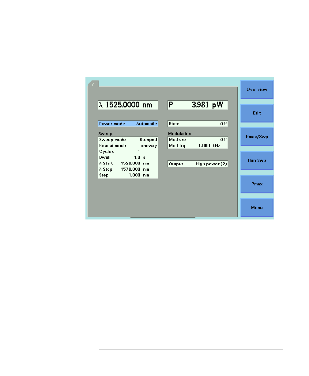
Tunable Laser Sources
How to Set the Power
Figure 5-1 Setting High Power parameters
99

Tunable Laser Sources
How to Set the Power
Figure 5-2 Setting Low SSE parameter
NOTE If you select <BOTH (MASTER:2)> or <BOTH (MASTER:1)> as the
regulated path, both channels output optical power. You can only view
or set the parameters for the primary optical output, for example, the
high power output for <BOTH (MASTER:2)>.
The LED beside the primary optical output is lit constantly, while the
LED beside the secondary optical output flashes. For example, if you
select <BOTH (MASTER:2)> as the regulated path, the LED beside
Output 2, the High Power Output, is lit constantly and the LEDbeside
Output 1, the Low SSE optical output, flashes.
100
 Loading...