


Operating and Programming Manual
HP 81541MM Lightwave
Multimeter Source Module
SERIAL NUMBERS
This manual applies to all instruments.
ABCDE
HP Part No. 81541-90011
Printed in the Federal Republic of Germany
First Edition
E1092


Notices
This document contains proprietary
information which is protected by
copyright. All rights are reserved.
No part of this document may be
photocopied, reproduced, or
translated to another language
without the prior written consent of
Hewlett-Packard GmbH.
c
Copyright 1992 by:
Hewlett-Packard GmbH
Herrenberger Str. 130
7030 Boeblingen
Federal Republic of Germany
Subject Matter
The information in this document is
subject to change without notice.
Hewlett-Packard makes no warranty
of any kind with regard to this
printed material, including, but not
limited to, the implied warranties of
merchantability and tness for a
particular purpose.
Hewlett-Packard shall not be liable
for errors contained herein or for
incidental or consequential damages
in connection with the furnishing,
performance, or use of this material.
Printing History
New editions are complete revisions
of the manual. Update packages,
contain additional and replacement
information to be incorporated into
the manual by the customer. The
date on the title page only changes
when a new manual is published.
When an edition is reprinted, all the
prior updates to the edition are
incorporated.
Warranty
This Hewlett-Packard instrument
product is warranted against defects
in material and workmanship for a
period of one year from date of
shipment. During the warranty
period, HP will, at its option, either
repair or replace products which
prove to be defective.
For warranty service or repair, this
product must be returned to a service
facility designated by HP. Buyer shall
prepay shipping charges to HP and
HP shall pay shipping charges to
return the product to Buyer.
However, Buyer shall pay all shipping
charges, duties, and taxes for
products returned to HP from
another country.
HP warrants that its software and
rmware designated by HP for use
with an instrument will execute its
programming instructions when
properly installed on that instrument.
HP does not warrant that the
operation of the instrument,
software, or rmware will be
uninterrupted or error free.
Limitation of Warranty
The foregoing warranty shall not
apply to defects resulting from
improper or inadequate maintenance
by Buyer, Buyer-supplied software or
interfacing, unauthorized
modication or misuse, operation
outside of the environmental
specications for the product, or
improper site preparation or
maintenance.
No other warranty is expressed or
implied. Hewlett-Packard specically
disclaims the implied warranties of
Merchantability and Fitness for a
Particular Purpose.
Control Serial Number: Edition 1 applies directly to all instruments.
Edition 1 : 1st March 1991 : 81541-90011 : E0391
: 1st October 1992 : 81541-90011 : E1092
Exclusive Remedies
The remedies provided herein are
Buyer's sole and exclusive remedies.
Hewlett-Packard shall not be liable
for any direct, indirect, special,
incidental, or consequential
damages whether based on contract,
tort, or any other legal theory.
Assistance
Product maintenance agreements
and other customer assistance
agreements are available for
Hewlett-Packard products.For any
assistance contact your nearest
Hewlett-Packard Sales and Service
Oce.Addresses are provided at
the back of this manual.
Certication
Hewlett-Packard Company certies
that this product met its published
specications at the time of
shipment from the factory.
Hewlett-Packard further certies
that its calibration measurements
are traceable to the United States
National Institute of Standards and
Technology, NIST (formerly the
United States National Bureau of
Standards, NBS) to the extent
allowed by the Institutes's
calibration facility, and to the
calibration facilities of other
International Standards Organization
members.


Safety Considerations
Before operation, review the instrument and manual, including the red safety
page, for safety markings and instructions
.You must follow these to ensure safe
operation and to maintain the instrument in safe condition.
Initial Inspection
Inspect the shipping container for damage. If there is damage to the container
or cushioning, keep them until you have checked the contents of the shipment
for completeness and veried the instrument both mechanically and electrically.
The Performance Tests give procedures for checking the operation of the
instrument. If the contents are incomplete, mechanical damage or defect is
apparent, or if an instrument does not pass the operator's checks, notify the
nearest Hewlett-Packard oce.
Warning
To avoid hazardous electrical shock, do not perform
electrical tests when there are signs of shipping damage to
any portion of the outer enclosure (covers, panels, etc.).
Line Power Requirements
The HP 81541MM operates when installed into the HP 8153A Lightwave
Multimeter mainframe
Operating Environment
The HP 8153A safety information summarizes the HP 81541MM operating
environment ranges. In order for the HP 81541MM to meet specications, the
operating environment must be within the limits specied for the HP 8153A.
Storage and Shipment
The module can be stored or shipped at temperatures between040
C and
+70C. Protect the module from temperature extremes that may cause
condensation within it.
v


Contents
C. HP 81541MM Specications
Suppelementary Performance Characteristics ...... .... C-2
Internal Digital Modulation . . . . . . . . . . . . . . . . . . C-2
Output Attenuation .... ...... ...... ..... C-2
Stability . . . . . . . . . . . . . . . . . . . . . . . . . . . C-2
D. Performance Tests
Introduction . . . . . . . . . . . . . . . . . . . . . . . . . .
Equipment Required . . . . . . . . . . . . . . . . . . . . . .
Test Record .......................... D-2
Test Failure .......................... D-2
Instrument Specication ...... ...... ...... .. D-2
Performance Tests . . . . . . . . . . . . . . . . . . . . . . . D-2
Output Power and Stability Tests .... ..... ...... D-3
1. Output Power Test ................... D-3
2. Attenuation Function Test................ D-4
3. Modulation Function Test ................ D-4
4. Stability Test ...................... D-4
E. Cleaning Procedures
Cleaning Materials . . . . . . . . . . . . . . . . . . . . . . . E-1
Cleaning Fiber/Front-Panel Connectors .. ...... ..... E-2
Cleaning Connector Interfaces .. ...... ...... ... E-2
Cleaning Connector Bushings . . . . . . . . . . . . . . . . . . E-3
Cleaning Detector Windows .................. E-3
Cleaning Lens Adapters ...... ...... ...... .. E-3
Cleaning Detector Lens Interfaces ...... ...... ... E-4
D-1
D-1
Contents-1

Figures
D-1. Performance Test Setup ................... D-3
Tables
C-1. HP 81541MM Specications . . . . . . . . . . . . . . . . . . C-1
Contents-2

C
HP 81541MM Specications
Specications describe the instrument's warranted preformance. Supplementary
performance characteristics describe the instrument's non-warranted typical
performance.
Because of the modular nature of the instrument, these performance
specications apply only to this module.You should insert these pages into the
appropriate section of the manual.
Table C-1. HP 81541MM Specications
Type
Central Wavelength
[1]
Fiber Type
Spectral Bandwidth (FWHM)
Output Power
CW-Stability
[1]
LED
850nm630nm
MM 50/125m
<
90nm
>
-17dBm
Short Term (15min, T=Constant)60.003dB
Long Term (6h, T=0 to 55C61K)60.03dB
Dimensions
Weight
Recalibration Period
[1]
After a warmup time of 60min. with output enabled. If previously
75mm H, 32mm W, 335mm D
(2.8"2
1.3"2
13.2"2
)
net 0.7kg (1.5lbs), shipping 1kg (2.2lbs)
1 year
stored at the same temperature, only 20min. warmup required.
HP 81541MM Specications C-1

Suppelementary Performance Characteristics
Internal Digital Modulation
You can select internal modulation frequencies of 270HZ, 1kHz, or 2kHz. All
outputs are pulse shaped, with a duty cycle of 50%.
Output Attenuation
The output can be attenuated from 0 to 6dB, in steps of 0.1dB.
Stability
The value of the long term stability doubles with just one minute warmup time
(source enabled).
C-2 HP 81541MM Specications

D
Performance Tests
Introduction
The procedures in this section test the optical performance of the instrument.
The complete specications to which the HP 81541MM is tested are given in
Table C-1. All tests can be performed without access to the interior of the
instrument. The performance tests refer specically to tests using the Diamond
HMS-10/HP connector.
Equipment Required
Equipment required for the performance test is listed below.
Note
Instrument/Accessory Recommended Model
Power Meter Standard
#C01
Multimeter Mainframe HP 8153A
Connector Adapter
(head)
Connector Interface HP 81000AI 2ea (08154-61701)
Multimode Fiber HP 81501AC
BNC to BNC Cable 8120-1840
Oscilloscope
The LED Source module under test can be inserted into the
second channel of the Power Meter Standard. In this case, the
second multimeter mainframe is not necessary.
HP 8153A Mainframe with
HP 81533A Optical Head Interface Module with
HP 81520A Optical Head
HP 81000AA
Performance Tests D-1
Test Record
Results of the performance test may be noted in the P
The Test Record can also be used as a permanent record and may be reproduced
without written permission from Hewlett-P
Test Failure
If the HP 81541MM fails any performance test, return the instrument to the
nearest Hewlett-Packard Sales/Service Oce for repair.
Instrument Specication
Specications are the performance characteristics of the instrument that are
certied. These specications, listed in Table C-1, are the performance standards
or limits against that the HP 81541MM can be tested. Appendix C also lists some
supplemental characteristics of the HP 81541MM and should be considered as
additional information.
Any changes in the specications due to manufacturing changes, design, or
traceability to the National Bureau of Standards will be covered in a manual
change supplement or revised manual. The specications listed in such a change
supercede any previously published.
ackard
erformance Test Record.
Performance Tests
The performance tests given in this section are separated into Output Power
Test and Stability Test. Perform each step in the tests in the order they are
given, using the corresponding test equipment.
Note
D-2 Performance Tests
Make sure that all optical connections in the test setups given in
the procedure are dry and clean.
Output Power and Stability Tests
Specications:
Optical output power of 50/125
Stability over 15 minutes at constant temperature:
Stability over 6h and61K env. temp. window:
m ber:
>
-17dBm
6
0.003dB
6
0.02dB
1. Output Power Test
a. Make sure that cable connectors and detector windows are clean.
b. Turn instruments on, enable the LED output of the HP 81541MM and allow
instruments to warm up for at least 60 minutes.
c. On the power meter:
i. Setto the wavelength displayed for the HP 81541MM source channel.
ii. Make sure that the CAL parameter on the power meter is set to zero
iii. With the connector adapter, on the optical head, covered with a plastic
5
cap, press
to zero the power meter.
4
Zero
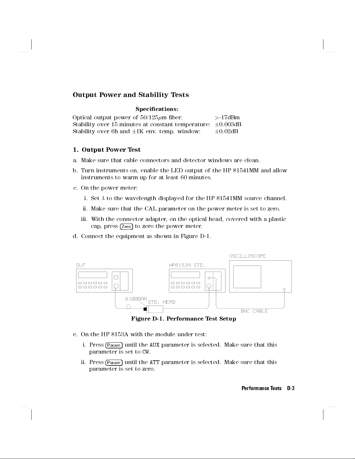
d. Connect the equipment as shown in Figure D-1.
Figure D-1. Performance Test Setup
e. On the HP 8153A with the module under test:
i. Press
4
Param
5
until the
AUX
parameter is selected. Make sure that this
parameter is set toCW.
ii. Press
4
Param
5
until the
ATT
parameter is selected. Make sure that this
parameter is set to zero.
.
Performance Tests D-3

f. Measure the output power and note the result in the Test Record.
2. Attenuation Function Test
g. On the power meter, press
4
Disp!Ref
5
. Press
4dB5
to select a display in dB.
h. Using the modify keys on the HP 8153A with the module under test, increase
the attenuation and check that the output power changes.
Note the reaction on the Test Record.
i. Set the attenuation to 0.0dB.
3. Modulation Function Test
j. Using a BNC cable, connect the power meter transducer output to the
oscilloscope input and set the oscilloscope as follows: 0.5V/DIV DC coupled,
1ms/DIV.
k. On the power meter, switch the autoranging o and select the -20dBm range.
l. On the HP 8153A with the module under test, press
4
Param
5
to select the
AUX
parameter. Monitor the frequency change on the oscilloscope as you set the
5
modulation to 270Hz, 1kHz, and then to 2kHz. Use
5
and
4
*
to modify the
4
+
modulation.
Note the reaction on the Test Record.
4. Stability Test
a. Enable the HP 81541MM LED output and allow the instruments to warm up
for 60 minutes.
b. Select the channel with the source.
i. Press
ii. Press
4
Param
4
Param
5
to select the
5
to select the
AUX
parameter. Set this parameter toCW.
ATT
parameter. Set this parameter to zero.
c. On the power meter:
i. Cover the input to the sensor with a plastic cap and press
the meter.
5
ii. Press
4
Param
to select theparameter. Set this parameter to the value
displayed for the source.
iii. Press
4
Param
5
to select theTparameter. Set this parameter to1s.
D-4 Performance Tests
4
Zero
5
to zero

d. Using the HP 81501A
C cable, connect the output of the source to the input
of the sensor. Make sure that the cable is xed and that it cannot be moved
during the measurement.
e. Select the
i. Press
ii. Press
MENU
mode on the power meter.
5
4
Record
4
5
and select the
Edit
to select
STABILTY
T_TOTAL
.
parameter. Set the
to 15 minutes.
iii. Press
f. When the stability test has completed, press
application. Press
4
Edit
5
and then
4
Edit
4
Exec
5
and then
5
to run the stability application.
5
to select the
4
More
5
4
Next
5/4
to display the
Prev
Divide this result by 2 to obtain the value for the stability:
DIF F
=
2
Stabil ity(dB
)
Note the result on the Test Record.
g. Repeat the stability measurement (steps e and f) with
T_TOTAL
DIFF
T_TOTAL
parameter
SHOW
result.
set to 6 hours.
Performance Tests D-5

Performance Test for the HP 81541MM
Test Facility:
Model HP81541MM Source Module
Page 1 of 3
Report No.
Date
Customer
Tested By
Serial No. Ambient temperature
Options Relative humidity %
Firmware Rev. Line frequency Hz
Special Notes:
C
D-6 Performance Tests

Performance Test for the HP 81541MM
Page 2 of 3
Test Equipment Used:
Description Model No. Trace No. Cal. Due Date
1. Lightwave Multimeter (Std.) HP 8153A
#C01
2. Opt. Head Interface Module HP 81533A
3. Optical Head 850nm HP 81520A
4. Lightwave Multimeter (DUT) HP 8153A
5. Connector Interface HP 81000AI N/A N/A
6. Connector Adapter HP 81000AA N/A N/A
7. Multimode Fiber HP 81501AC N/A N/A
8. BNC to BNC Cable P/N 8120-1840 N/A N/A
9. Oscilloscope
10.
11.
12.
13.
14.
15.
16.
17.
Performance Tests D-7

Performance Test for the HP 81541MM
Page 3 of 3
Model HP 81541MM LED Source Module No. Date
Test Minimum Maximum Measurement
No.Test Description Spec. Result Spec. Uncertainty
I.
Output Power Test
Output Power -17dBm
II.
Attenuation Function Test
Passed (P)/Failed (F)
III.
Modulation Function Test
Passed (P)/Failed (F)
IV.
Stability Tests
Stability (15min.) -0.003dB +0.003dB
Stability (6h.) -0.02dB +0.02dB
6
0.5dB (610.14%)
D-8 Performance Tests

Cleaning Procedures
E
In general,
connectors may be used dry or wet. Dry means without index matching
compound. If there is a need to use an index matching compound, use only HP
index matching oil (part number 8500-4922). Clean the connectors, interfaces
and bushings carefully each time after use.
Cleaning Materials
Lens Cleaning Paper 9300-0761
Special Cleaning Tips 9300-1351
Blow Brush 9300-1131
Adhesive Cleaning tape 15475-68701
Isopropyl Alcohol Not available from HP. This should be available from
Pipe Cleaner
whenever possible use physically contacting dry connectors
HP P/N
any local pharmaceutical supplier.
. Fiber
Cleaning Procedures E-1

Cleaning Fiber/Front-Panel Connectors
1. In order to clean the instrument front panel connector remove the connector
interface.
2. Apply some isopropyl alcohol to the lens cleaning paper and clean the
surface and the ferrule of the connectors.
3. Using a new dry piece of cleaning paper wipe the connector surface and
ferrule until they are dry and clean.
4. Lightly press the adhesive tape several times against the connector surface to
remove any remaining particles. After use store the tape in the container.
5. Protect the connector surface with a cap.
Cleaning Connector Interfaces
Apply some isopropyl alcohol to the pipe cleaner and wash the inside of the
connector interface.
Using a new dry pipe cleaner, dry the inside of the connector interface.
Remove the brush part from the blow brush and blow air through the inside
of the interface to remove any remaining particles.
Note
E-2 Cleaning Procedures
If any index matching compound was used, use an ultrasonic
bath with isopropyl alcohol to clean the connector interfaces.

Cleaning Connector Bushings
As used on the HP 8158B and HP 81000AS/BS.
Normally the connector bushings require no cleaning. However
that cleaning is necessary, use only the blow brush with the brush part
removed.
Caution
Cleaning Detector Windows
As used on the HP 81520A and HP 81521B
1. Use the blow brush to remove any particles from the surface
2. Wipe the surface with cleaning paper or special cleaning tips
Cleaning Lens Adapters
NEVER insert any cleaning tool into the bushing as this may
aect the optical system.
NEVER use any index matching compound, cleaning uid or
cleaning spray.
.
, if it appears
.
.
Caution
1. Using the blow brush, remove dust.
2. Wipe the surfaces with the special cleaning tips.
Do not use any cleaning uid or cleaning spray.
Cleaning Procedures E-3

Cleaning Detector Lens Interfaces
As used on the HP 81522A and HP 8140A and HP 8153A detector modules
.
Normally, the lens interface can be cleaned by using the blow brush. If adhesive
dirt must be removed perform as follows:
1. Using the blow brush, remove the dust from the lens surface.
2. Press the special cleaning tip to the lens surface and rotate the tip.
Note
Use alcohol for cleaning only then when above procedure does
not help or if the dirt is caused by oil or fat.
E-4 Cleaning Procedures
 Loading...