


S
Agilent 81130A 400/660MHz Pulse/Data Generator
Quick Start Guide
S1

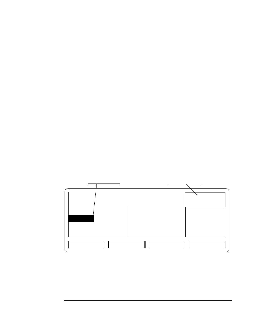
Front Panel Display and Softkeys
Mode / Parameter Area Modify / Enter Area
Use the CURSOR keys to
move the entry focus to a
mode, parameter format,
Channel 1
Column
or
parameter value
Channel 2
Column
Use the KNOB to select a
mode or modify parameters
and formats
Press ENTER or a UNIT key to
confirm parameter changes
ON Freq 50.00MHz OFF
1
OFF OFF
Entry
Focus
Delay
DtyCyc
Press a SOFTKEY to access
the required entry screen
0ps
50.0%
Screen Selection Area
Delay 0ps
Width 100.0ns
TIMING PATTERNLEVELSMODE/TRG
2
MODIFY
50.0
%
GRAPH
MORE
Press MORE key to access
the additional screen menus:
LIMITS TRG-LEV MEMCARD CONFIG

Quick Start Guide
Agilent 81130A 400/660 MHz
Pulse/Data Generator
Part No. 81130-91020
Printed in Germany March 2000
Edition 1.0, E0300

Notice
Notice
Copyright
1998 Agilent Technologies 1998, 2000. All rights reserved.
No part of this manual may be reproduced in any form or by any means
(including electronic storage and retrieval or translation into a foreign
language) without prior agreement and written consent from Agilent
Technologies Inc. as governed by United States and international
copyright laws.
Notice
The material contained in this document is subject to change without
notice. Agilent Technologies makes no warranty of any kind with regard
to this material, including, but not limited to, the implied warranties of
merchantability and fitness for a particular purpose. Agilent
Technologies shall not be liable for errors contained herein or for
incidental or consequential damages in connection with the furnishing,
performance, or use of this material.
Warranty
This Agilent Technologies product has a warranty against defects in
material and workmanship for a period of three years from date of
shipment. During the warranty period, Agilent Technologies will, at its
option, either repair or replace products that prove to be defective. For
warranty service or repair, this product must be returned to a service
facility designated by Agilent Technologies. The Buyer shall pay Agilent
Technologies round-trip travel expenses. For products returned to
Agilent Technologies for warranty service, the Buyer shall prepay
shipping charges to Agilent Technologies and Agilent Technologies shall
pay shipping charges to return the product to the Buyer. However, the
Buyer shall pay all shipping charges, duties and taxes for products
returned to Agilent Technologies from another country.
4

Notice
Agilent Technologies warrants that its software and firmware designated
by Agilent Technologies for use with an instrument will execute its
programming instructions when properly installed on that instrument.
Agilent Technologies does not warrant that the operation of the
instrument software, or firmware, will be uninterrupted or error free.
Limitation of Warranty
The foregoing warranty shall not apply to defects resulting from
improper or inadequate maintenance by the Buyer, Buyer-supplied
software or interfacing, unauthorized modification or misuse, operation
outside of the environmental specifications for the product, or improper
site preparation or maintenance. No other warranty is expressed or
implied. Agilent Technologies specifically disclaims the implied
warranties of merchantability and fitness for a particular purpose.
Exclusive Remedies
The remedies supplied are the Buyer's sole and exclusive remedies.
Agilent Technologies shall not be liable for any direct, indirect, special,
incidental, or consequential damages, whether based on contract, tort or
any other legal theory.
Certification
Agilent Technologies certifies that this product met its published
specifications at the time of shipment. Agilent Technologies further
certifies that its calibration measurements are traceable to the United
States Institute of Standards and Technology, to the extent allowed by
the Institute's calibrating facility, and to the calibration facilities of other
International Standards Organization members.
Services and Support
Any adjustment, maintenance, or repair of this product must be
performed by qualified personnel. Contact your customer engineer
through your local Agilent Technologies Service Center. You can find a
list of local service representatives on the Web at:
http://www.agilent.com/Service/English/index.html
5

Safety Summary
Safety Summary
The following general safety precautions must be observed during all
phases of operation of this instrument. Failure to comply with these
precautions or with specific warnings elsewhere in this manual violates
safety standards of design, manufacture, and intended use of the
instrument. Agilent Technologies Inc. assumes no liability for the
customer's failure to comply with these requirements.
General
This product is a Safety Class 1 instrument (provided with a protective
earth terminal). The protective features of this product may be impaired
if it is used in a manner not specified in the operation instructions.
All Light Emitting Diodes (LEDs) used in this product are Class 1 LEDs
as per IEC 60825-1.
Environmental Conditions
This instrument is intended for indoor use in an installation category II,
pollution degree 2 environment. It is designed to operate at a maximum
relative humidity of 95% and at altitudes of up to 2000 meters. Refer to
the specifications tables for the ac mains voltage requirements and
ambient operating temperature range.
Before Applying Power
Verify that the product is set to match the available line voltage, the
correct fuse is installed, and all safety precautions are taken. Note the
instrument's external markings described under Safety Symbols on
page 8.
6

Safety Summary
Ground the Instrument
To minimize shock hazard, the instrument chassis and cover must be
connected to an electrical protective earth ground. The instrument must
be connected to the ac power mains through a grounded power cable,
with the ground wire firmly connected to an electrical ground (safety
ground) at the power outlet. Any interruption of the protective
(grounding) conductor or disconnection of the protective earth terminal
will cause a potential shock hazard that could result in personal injury.
Fuses
Only fuses with the required rated current, voltage, and specified type
(normal blow, time delay, etc.) should be used. Do not use repaired fuses
or short-circuited fuse holders. To do so could cause a shock or fire
hazard.
Do Not Operate in an Explosive Atmosphere
Do not operate the instrument in the presence of flammable gases or
fumes.
Do Not Remove the Instrument Cover
Operating personnel must not remove instrument covers. Component
replacement and internal adjustments must be made only by qualified
service personnel.
Instruments that appear damaged or defective should be made
inoperative and secured against unintended operation until they can be
repaired by qualified service personnel.
7

Safety Summary
Safety Symbols
Caution (refer to accompanying documents)
Protective earth (ground) terminal
In the manuals:
WARNING
CAUTION
The WARNING sign denotes a hazard. It calls attention to a
procedure, practice, or the like, which, if not correctly performed
or adhered to, could result in personal injury. Do not proceed
beyond a WARNING sign until the indicated conditions are fully
understood and met.
The CAUTION sign denotes a hazard. It calls attention to an operating
procedure, or the like, which, if not correctly performed or adhered to,
could result in damage to or destruction of part or all of the product. Do
not proceed beyond a CAUTION sign until the indicated conditions are
fully understood and met.
8

About this Book
About this Book
This quick start guide helps you to quickly get familiar with the features
and the user interface of the Agilent 81130A Pulse Generator.
Chapter 1 Introducing the Agilent 81130A Pulse and Data Generator
on page 15 gives a general overview of the Agilent 81130A, its features,
the user interface, and the steps required for operating the instrument.
Chapter 2 Getting Started on page 31 gives the setup information for
some real-world signal examples, which can easily be used by varying
only some parameter values.
Chapter 3 Using the Agilent 81130A on page 59 provides complete
information on the user interface screens.
Installation and maintenance are described in Appendix A Installation
& Maintenance on page 99.
For specifications and information on operating the instrument by means
of remote control, please refer to the Reference Guide, p/n 81130-91021.
9

About this Book
Conventions Used in this Book
This book uses certain conventions to indicate elements of the
Agilent 81130As user interface. The following table shows some
examples:
Softkeys Press the MODE/TRG softkey to access the Mode/
Trigger screen.
Hardkeys Press the MORE key to switch to the alternative
softkey layout.
Alternate Keys Press SHIFT + 0 (ON/OFF1) to switch on output 1.
The alternate key labelwhich is selected by
pressing the SHIFT keyis given in parentheses.
Screen Quotes Move the entry focus down to P
turn the knob to select
INTERNAL
ULSE-PERIOD
PLL.
and
Entry Focus The highlight field, that can be moved with the
cursor keys, to change modes, parameters, or
parameter formats.
10

Contents
Notice ......................................................................................... 4
Safety Summary ......................................................................... 6
About this Book ......................................................................... 9
Chapter 1
Chapter 2
Introducing the Agilent 81130A Pulse and
Data Generator
What you can do with the Agilent 81130A ............................ 16
The Front Panel ....................................................................... 18
Operating the Agilent 81130A ................................................ 20
Switching On the Instrument .............................................................. 20
The Basic Screens ................................................................................. 21
Adjusting Parameters ........................................................................... 24
Switching the Outputs On and Off ...................................................... 27
Using the Special Function Keys ........................................................ 27
Help is Available ...................................................................... 29
The Rear Panel ........................................................................ 30
Getting Started
Setting Up a Clock Signal ....................................................... 32
Setting Up a Burst Signal ....................................................... 37
Setting Up a Serial Data Stream ............................................ 41
Setting Up an Edge-Displacement Signal .............................. 46
Setting Up a Serial Data Sequence ........................................ 51
xi

Contents
Chapter 3
Using the Agilent 81130A
The Mode/Trigger Screen ....................................................... 60
Overview ................................................................................................. 60
Continuous Pulses Mode ...................................................................... 63
Continuous Burst Mode ........................................................................ 64
Continuous Pattern Mode .................................................................... 65
Started Pulses Mode ............................................................................. 66
Started Burst Mode ............................................................................... 67
Started Pattern Mode ............................................................................ 68
Gated Pulses Mode ................................................................................ 69
Gated Burst Mode ................................................................................. 70
Gated Pattern Mode .............................................................................. 71
The Timing Screen .................................................................. 72
The Levels Screen ................................................................... 76
The Pattern Screen ................................................................. 79
The Segment Editor .............................................................................. 83
Block Editing Functions ....................................................................... 85
The Limits Screen ................................................................... 86
The Trigger-Level Screen ....................................................... 87
The Memory Card Screen ....................................................... 89
The Configuration Screen ...................................................... 92
The Output Screens ................................................................ 95
Warnings and Errors .............................................................. 96
xii

Contents
Appendix A
Installation & Maintenance
Initial Inspection ................................................................... 100
Standard Deliverables ........................................................................ 101
Options and Accessories: ................................................................... 102
Power Requirements ............................................................. 104
Power Cable ........................................................................... 106
Ventilation Requirements ..................................................... 107
Thermal Protection ............................................................................. 107
Battery ................................................................................... 108
Battery Replacement .......................................................................... 109
Operating Environment ........................................................ 110
Cleaning Recommendation ................................................... 111
Acoustic Noise Emission ....................................................... 112
xiii

Contents
xiv

1Introducing the
Agilent 81130A Pulse and
1
Data Generator
The purpose of the introduction chapter is to give a general overview of
the Agilent 81130A.
The main features and use models are described in What you can do
with the Agilent 81130A on page 16.
Operating the instrument via the front panel user interface is described in
The Front Panel on page 18 and Operating the Agilent 81130A on
page 20.
Help is Available on page 29 shortly introduces the Agilent 81130As
on-line help system.
Finally, The Rear Panel on page 30 takes a look at the back of the
Agilent 81130A.
15

Introducing the Agilent 81130A Pulse and Data Generator
What you can do with the Agilent 81130A
What you can do with the
Agilent 81130A
This section introduces the basic features and use models of the
Agilent 81130A Pulse Generator.
Basic Features
The Agilent 81130A is a pulse and data generator with one or two output
channels. It is capable of generating all standard pulses, bursts, and
patterns of pulses needed to test current logic technologies (for example,
TTL, CMOS, ECL, PECL) and other digital designs up to 400 MHz/3.8V or
660 MHz/2.5V, depending on the installed output module(s).
The instrument features
placement accuracy and accurate delay and deskew even at maximum
output frequency. This contributes to reliable measurements and more
accurate and confident characterizations of the device under test (DUT).
The instrument uses an accurate and stable
For even more accuracy, it can be connected to an
reference
For programming complex
packages, 64 kbit memory are available to store individual patterns. Each
pattern can consist of up to four segments. Loops can be programmed
over single segments or groups of consecutive segments. The segments
can include
.
pseudo-randomly generated data
precision timing
data patterns
, providing highest edge
internal PLL oscillator
external frequency
, such as communication
.
.
If the Agilent 81130A is equipped with two output modules, the output
channels can be used separately or be
signals.
Complete signal setups can be stored locally (5 internal non-volatile
registers available) or on a
16
memory card
added
digitally to form complex
.

Introducing the Agilent 81130A Pulse and Data Generator
What you can do with the Agilent 81130A
Benchtop Testing
The Agilent 81130A features a graphic display showing all pulse
parameters at a glance. The cursor keys and the modify knob allow fast
and simple operation.
The user interface is designed to minimize the time invested in getting
familiar with the instrument. After familiarization, the instrument
supports quick setups of signals. This leaves you free to concentrate on
the measurement task and testing of the DUT.
Automated Testing
The Agilent 81130A features an GP-IB/SCPI-conform command structure
for all features. Using this programming interface, the instrument can be
easily integrated into all phases of test system development such as
planning rack integration and test program generation.
Programs designed for the Agilent 81130A are compatible with all other
models of the Agilent 81100 family.
NOTE
For a command reference list, please refer to the Reference Guide, part
number 81130-91021.
Upgrade Capability
It is possible to upgrade the instrument with a second channel if only one
channel has been ordered originally. There are two types of output
modules available for the Agilent 81130A. You can only use one type of
output module within one instrument.
Output Module Description
Agilent 81131A 400 MHz, 3.8 V
Agilent 81132A 660 MHz, 2.5 V
17

Introducing the Agilent 81130A Pulse and Data Generator
The Front Panel
The Front Panel
When used for benchtop testing, the instrument is mainly operated from
the front panel.
Front Panel
Switch
NOTE
Special Function
Keys
Softkeys
front panel switch
The
When the front panel switch is off, the instrument is in standby mode.
The instrument is disconnected from the AC line power only by
disconnecting the power cord.
The four keys below the display are the
keys). The current function of each softkey is indicated in the
corresponding box on the display.
Pressing the MORE key changes the softkey layout.
The other keys (
and the
operating the instrument (see Operating the Agilent 81130A on
page 20).
rotary knob
MORE Key
is used to switch on and off the instrument.
special function keys, data entry keys, cursor keys
are used to select and modify parameters when
Data Entry
Keys
Inputs and Outputs
softkeys
Cursor
Keys
(software-controlled
Rotary
Knob
)
18

Introducing the Agilent 81130A Pulse and Data Generator
The major inputs and outputs of the instrument are available at the front
panel:
The external input (EXT INPUT) can be used to connect an external
arming source (started or gated modes). For details, please refer to
The Mode/Trigger Screen on page 60.
The clock reference input (CLK/REF INPUT) can be used to connect
either an external clock signal or a reference signal for the internal
PLL (see Pulse Period Source on page 94 and PLL Reference on
page 94).
The trigger signal (TRIGGER OUT) marks the start of the pulse
period or of parts of a pattern (see The Mode/Trigger Screen on
page 60). You can set the output levels according to the used
technology (TTL, ECL, PECL) or enter test-specific values (see The
Trigger-Level Screen on page 87).
The OUTPUT connectors provide the signal output (normal and
inverted), the indicators show the current state of the output (on or
off).
The Front Panel
NOTE
For information on the use of the memory card slot, refer to The
Memory Card Screen on page 89.
19

Introducing the Agilent 81130A Pulse and Data Generator
Operating the Agilent 81130A
Operating the Agilent 81130A
This section guides you through the first steps when operating the
Agilent 81130A via the user interface.
NOTE
For information on operating the Agilent 81130A via remote control,
please refer to the Reference Guide, part number 81130-91021.
Switching On the Instrument
After switching on the instrument the display indicates that the
instrument selftest is running. This can take several seconds to complete.
If the selftest fails, you see a flashing E at the bottom of the screen. Press
the HELP key to see a list of the selftest error messages. Use the knob or
the cursor keys to scroll through the list if necessary.
To return to normal operation press HELP again. Note that the selftest
error messages are removed from the error queue after this.
20

Introducing the Agilent 81130A Pulse and Data Generator
Operating the Agilent 81130A
The Basic Screens
The major parameters for pulse generation can be set up in 3 screens.
For setting up patterns there are two more basic screens.
Mode/Trigger screen
The
and trigger modes with respect to the signal required.
allows you to set the fundamental operating
Press the MODE/
TRG softkey to
access this screen.
CONTINUOUS
PULSES
MODIFY
*Continous
Started
Gated
TIMING PATTERNLEVELSMODE/TRG
In this screen, you can set up the signal to be gated, started or
continuous, and to be a pulse stream, a burst (several pulses followed by
a pause) or a pattern.
In the lower section you can specify the trigger source and control the
trigger output (in started and in gated mode).
21

Introducing the Agilent 81130A Pulse and Data Generator
Operating the Agilent 81130A
OFF OFF
1
OFF OFF
Delay
Width
LeadE 0.8ns
TraiE =LeadE
0ps Delay 0ps
100.0ns
TIMING PATTERNLEVELSMODE/TRG
Timing Screen
Press the TIMING
OR
LEVELS softkey
to access these
screens.
Timing screen
The
and the
Levels screen
allow you to specify timing
and level parameters for the signals to be generated.
1.000
sPer
µµµµ
Width 100.0ns
LeadE 0.8ns
TraiE =LeadE
2
MODIFY
ON OFF
1.000
1
OFF OFF
Separate Outputs
s
µµµµ
High
Low
+2.50V
+0.0MV
TIMING PATTERNLEVELSMODE/TRG
2
Offset 0.0MV
Amplit 1.00V
MODIFY
+2.50
V
M
Levels Screen
In the Timing screen you can set up the clock frequency and, for output 1
and 2, the timing for the signals (delay, pulse width, duty cycle, ...).
The Levels screen allows you to specify the level parameters for the
signals to be generated. You can select between preset values of different
technologies and/or adjust values according to individual requirements.
Set the values in terms of high/low level or offset/amplitude. If the
Agilent 81130A is equipped with two output modules, the channels can
be set as separate outputs or to be digitally added.
Pressing SHIFT + MORE (GRAPH) when the Timing or the Levels screen is
displayed, toggles between the textual display and a graphical
representation of the parameters.
1
OFF
OFF
2
OFF
OFF
TIMING PATTERNLEVELSMODE/TRG
Width
100.0
ns
In both screens, you can switch on and off the outputs. Their status (ON
or OFF) is indicated on screen and by an LED next to the output
connector.
22

Introducing the Agilent 81130A Pulse and Data Generator
Pattern screen
The
consisting of up to 4 segments. You can specify the length of each
individual segment and then compose the sequence by specifying a reentrance point (where the instrument resumes after the end of the
sequence) and/or a loop over consecutive segments.
allows you to compose a pattern sequence
Operating the Agilent 81130A
Segment
Select
Resume
Indicator
(in gated/started
mode only)
Loop
Indicator
Segment Length Loopcnt Update
1
32 1
2 0
3 0
4 0
TIMING PATTERNLEVELSMODE/TRG
To set up the data of a segment, you call the
the segment to be edited and pressing the ENTER key.
Segment 1
Address 1
CH1 Data 1 0 0 0 0 0 0
UPDATE
Length 32
1
segment editor
CH2 Data 0 0 0 0 0 0 0
Both 1 0 0 0 0 0 0
ENTER
*Edit Segm
by selecting
= ADDR
0 to Reset
1 to Set
Toggle
±±±±
TIMING PATTERNLEVELSMODE/TRG
Per channel you can select from different predefined data formats (such
as high, or low, or pseudo-random data segment), you can enter data by
using block editing functions, and you can enter the data bit by bit.
23
Introducing the Agilent 81130A Pulse and Data Generator
Operating the Agilent 81130A
Adjusting Parameters
Adjusting parameters within a screen, requires two steps:
selecting the parameter
adjusting its value
Some parameters allow different formats of their values. For example,
the pulse width can be displayed and entered as an absolute value, as
duty cycle (percentage of the period), or as the delay of the trailing edge.
The following sections show the standard procedure for adjusting
parameters, and list some features useful for the advanced user.
Standard Procedure
To experience the standard procedure for adjusting parameters, consider
the following example where the duty cycle is set to 50%.
1
Press the TIMING softkey to access the Timing screen.
2
Use the cursor keys to select the W
parameter.
IDTH
Selection Modify/Enter Area
OFF Per 1.000 µs OFF
1
OFF OFF
Delay
Width
0ps
100.0ns
Delay 0ps
Width
2
100.0ns
MODIFY
*Width
DutyCycle
TrailDel
TIMING PATTERNLEVELSMODE/TRG
The available formats for the pulse width parameter are displayed in
the Modify/Enter area.
24

Introducing the Agilent 81130A Pulse and Data Generator
Operating the Agilent 81130A
When changing the
parameter format,
the instrument
automatically
recalculates the
value.
3
Turn the knob to select D
The selected setting is indicated by an *.
4
Move the cursor to the right to select the duty cycle value.
5
Use the data entry keys or the knob to enter the required value: 50.
6
Press the ENTER key to confirm your selection.
UTYCYCLE
.
ON Per 1.000µs OFF
1
OFF OFF
Delay
DtyCyc
0ps
50.0%
Delay 0ps
Width 100.0ns
2
MODIFY
50.0
%
TIMING PATTERNLEVELSMODE/TRG
If you need to specify a unit for a parameter, simply press the appropriate
unit key (
With this small example, you have learned the basic steps required for
adjusting parameters. For a complete reference of parameters and
formats available in the individual screens, refer to Chapter 3 Using the
Agilent 81130A on page 59.
NANO, MICRO/MEGA, MILLI/KILO
) instead of the ENTER key.
25

Introducing the Agilent 81130A Pulse and Data Generator
Operating the Agilent 81130A
Advanced Procedures
The following features can be used to make operation more comfortable.
Selecting parameters
SHIFT
SHIFT
SHIFT
NOTE
Most keys of the front panel have an additional function. The SHIFT
key provides fast access to the additional functions of the data entry
keys and the special function keys.
For example, it is possible to quickly access the pulse width
parameter by pressing SHIFT + 6 (WIDTH). The entry focus will be
positioned on the corresponding editing field.
Changing the step size
When modifying a value in the Modify/Enter area, pressing the SHIFT
key followed by cursor left/right moves the cursor to a different digit
in the displayed number.
Thus, you can change the step size for parameter change before you
vary the value either with the up/down cursor keys or the knob.
Overprogramming
Pressing the SHIFT key while turning the knob, it is possible to exceed
specified parameter ranges to utilize the instrument to its limits.
Proper operation of the instrument outside of the specified ranges is not
guaranteed. It is recommended to have the output switched on when
overprogramming to have the internal error check system activated. This
error check system warns you about impossible settings.
26

ON/OFF1
0
Introducing the Agilent 81130A Pulse and Data Generator
Operating the Agilent 81130A
Switching the Outputs On and Off
When you switch the instrument on, the outputs and inverted outputs are
switched off to protect the device under test. The LED indicator next to
the connector indicates the output state.
For example, to switch output 1 on or off
either press SHIFT + 0 (ON/OFF1),
or move the cursor to the ON/OFF parameter in the Timing or Levels
screen and select the appropriate value by turning the knob.
To switch on or off output 2 and/or the inverted outputs, proceed in the
same way. You can use the following short cuts:
Short Cut Output
SHIFT + 0 (ON/OFF1) Normal Out 1
MAN
RECALL
STORE
SHIFT + . (decimal point) (ON/OFF1
SHIFT + +/- (ON/OFF2) Normal Out 2
SHIFT + ENTER (ON/OFF2
) Inverted Out 2
) Inverted Out 1
Using the Special Function Keys
The instrument provides the following special function keys:
The MAN key can be used to run and to stop the instrument, and, in
triggered or gated mode, to manually arm and/or trigger the
instrument if there is no other source available (see The Mode/
Trigger Screen on page 60).
The STORE key can be used to store/recall to/from 1 to 4 individual
settings in the instrument memory.
In the internal memory location 0 there is a default setting stored.
Pressing SHIFT + STORE (RECALL) and selecting 0 resets the instrument to
the default setting.
27

Introducing the Agilent 81130A Pulse and Data Generator
Operating the Agilent 81130A
SHIFT
LOCAL
HELP
The SHIFT key provides fast access to additional functions.
When the front panel controls are locked in remote control, pressing
the SHIFT key unlocks the front panel controls.
The HELP key provides access to the instruments on-line help or in
warning or error state, access to Warning/Error Report screen.
Pressing SHIFT + HELP (AUTOSET) sets the instrument to a valid
setting based on the current period setting.
28

Help
Introducing the Agilent 81130A Pulse and Data Generator
Help is Available
Help is Available
Whenever you are in doubt or the instrument signals warnings or errors,
press the HELP key.
If there are no warnings or errors pending, pressing the HELP key
displays information on the currently selected parameter, the parameter
help. More information is available within the help system:
Parameter Help
The help information gives a short description of the parameter or
setting options and the corresponding SCPI command(s) syntax for
programming the parameter or setting.
If there is more than one screen available (indicated by small arrows),
use the knob or the cursor keys to scroll through the help
information.
To access parameter help from other screens of the help system,
press the ON FIELD softkey.
Warnings and
Errors
Exit Help
Concept Help
Pressing the CONCEPT softkey within the help system displays a short
description of the instrument.
Serial Numbers and Software Revision
Pressing the SERIAL # softkey within the help system displays
information on serial numbers and software revision codes of the
instrument.
If there are warnings or errors pending (indicated by a flushing W or E),
pressing the HELP key displays a list of the current messages. Using the
ERROR QU and WARNING softkeys, you can toggle between both lists. For
more information on warnings and errors, see Warnings and Errors on
page 96.
To exit from the help system, press the HELP key again, or press the EXIT
HELP softkey.
29

Introducing the Agilent 81130A Pulse and Data Generator
The Rear Panel
The Rear Panel
The rear panel always provides two connectors:
The external input (EXT INPUT) can be used to connect an external
arming source (started or gated modes).
The input connector for external clock or PLL reference (CLOCK/
REF INPUT) can be used if a higher frequency accuracy is required.
The GP-IB connector providing the interface for remote control.
The following figure shows the rear panel view with the option UN2.
CLK/REF InputExternal Input GP-IB Connector
Inputs and Outputs
With option UN2 the major inputs and outputs of the instrument (as
described in The Front Panel on page 18) are available at the rear
panel:
external input (EXT INPUT)
clock/reference input (CLK/REF INPUT)
trigger signal (TRIGGER OUT)
signal output (OUTPUT)
30
Fuse Holder
AC Line Socket Serial Number

2
2Getting Started
The intention of this chapter is to give the necessary steps to set up
generic signals for first-time users of the Agilent 81130A.
This chapter provides examples for the following types of signals:
Setting Up a Clock Signal on page 32
Setting Up a Burst Signal on page 37
Setting Up a Serial Data Stream on page 41
Setting Up an Edge-Displacement Signal on page 46
Setting Up a Serial Data Sequence on page 51
At the end of each example, the required set of device commands is listed
to provide programming examples. For further information on the
commands and a complete command reference please refer to the
Reference Guide, p/n 81130-91021.
The examples are intended to be performed one after the other.
Therefore, the first example provides the most detailed instructions,
while the other examples are described on a higher level.
31

Getting Started
Setting Up a Clock Signal
Setting Up a Clock Signal
Ta sk
Instructions
Set up a continuous clock signal with 50 MHz frequency, a duty cycle of
50 %, a high level of 2.5 V and a low level of 0 V.
Duty Cycle = 50 %
2.5 V
0.0 V
f = 50 MHz
To set the
1
Reset all parameters and modes by pressing SHIFT + STORE (RECALL) + 0.
2
Press the MODE/TRG softkey to enter the Mode/Trigger screen.
Trigger mode CONTINUOUS and operating mode PULSES are
selected by default.
CONTINUOUS
operating mode and trigger mode
PULSES
as required:
MODIFY
*Continous
Started
Gated
32
TIMING PATTERNLEVELSMODE/TRG

Setting Up a Clock Signal
Getting Started
To set the
1
Press the TIMING softkey to enter the Timing screen.
2
Press SHIFT + 0 (ON/OFF1).
This turns on the Output 1 and activates the internal error check to
detect parameter conflicts.
3
Move the entry focus to P
4
Move the entry focus to the right (to the frequency entry field) and
enter a value of 50 MHz by pressing 5 + 0 +
A warning is displayed, indicating a potential conflict in your settings.
The conflict will be solved in the next steps.
5
If you want to view the warning message, press the HELP key. Return
by pressing the HELP key again.
6
Move the entry focus down left to W
D
7
Move the entry focus to the right and enter 50 % by typing 5 + 0 +
ENTER.
Delay
DtyCyc
timing parameters
UTYCYC
.
as required:
and turn the knob to select F
ER
ON Freq 50.00MHz OFF
1
OFF OFF
0ps
50.0%
Delay 0ps
Width 100.0ns
MICRO/MEGA
of output 1 and select
IDTH
.
2
REQUENCY
MODIFY
50.0
.
%
TIMING PATTERNLEVELSMODE/TRG
33

Getting Started
Setting Up a Clock Signal
8
Press SHIFT + MORE (GRAPH) or the TIMING softkey to see a preview of
your signal.
1
ON
OFF
2
OFF
OFF
You can modify the parameter displayed in the Modify/Enter area,
and immediately check how your changes affect the signal. Use the
cursor keys to switch to another parameter.
9
Press SHIFT + MORE (GRAPH) or the TIMING softkey to return to the
textual screen.
To set the
TIMING PATTERNLEVELSMODE/TRG
level parameters
DutyCyc1
50.0
%
as required:
1
Press the L
2
Move the entry focus to O
turn the knob to select H
3
Move the entry focus to the L
ENTER key. In the same way, enter 2.5 V for the high level.
softkey to enter the Levels screen.
EVELS
FFSET/AMPLIT
IGH-LOW
OW
in the output 1 column and
.
entry field, enter 0 and press the
ON OFF
1
OFF OFF
2
Separate Outputs
High
Low
+2.50V
+0.0MV
Offset 0.0MV
Amplit 1.00V
TIMING PATTERNLEVELSMODE/TRG
34
MODIFY
+2.50
M
V

Setting Up a Clock Signal
Getting Started
NOTE
There is also a graphical screen available for the level parameters.
Here is the signal as displayed on an Agilent 54810A Infinium
oscilloscope. Use the generators TRIGGER OUT to trigger the scope.
35

Getting Started
Setting Up a Clock Signal
Programming
Example
If you want to include this clock signal in your GP-IB program, use the
following command lines. The comment lines starting with a # are not
required.
# Reset the instrument to start from a defined, default status.
*RST
# Switch off the automatic display update to increase programming
# speed.
:DISPlay OFF
# Internal PLL has to be set as period source.
# Set the frequency to 50 MHz and the duty cycle to 50 %
:FREQuency 50 MHZ
:PULSe:DCYCle 50
# Set the high level to 2.5 Volts, the low level to 0.0 Volts.
:VOLTage:HIGH 2.5V
:VOLTage:LOW 0V
# Enable the output.
:OUTPut ON
36

Setting Up a Burst Signal
Setting Up a Burst Signal
Getting Started
Ta sk
Instructions
Set up a burst signal with a burst repetition of 4 clocks. Each burst
consists of two pulses at a period of 100 ns. The pulse width is 25 ns. The
levels are 2 Vpp amplitude and 0 V offset. On the second channel the
clock reference is generated. The signals are issued while the MAN key is
pressed.
Pulse Width = 25 ns
1 V
Output 1
Burst Signal
Output 2
Clock Signal
To set the
Trigger
Out
0 V
1 V
Pulse Period = 100 ns
1 V
0 V
1 V
Burst Period = 4 clocks
operating mode and trigger mode
as required:
1
Reset all parameters and modes by pressing SHIFT + STORE + 0.
2
Press the MODE/TRG softkey to enter the Mode/Trigger screen.
3
Move the entry focus to CONTINUOUS and turn the knob to select
G
.
ATED
4
Move to PULSES and select BURST
5
Move to PULSES OUT 1 and select 2.
6
Move to OUT 2 and select 4.
OF
.
37

Getting Started
Setting Up a Burst Signal
7
Move to BURST PERIOD and select 4 clocks.
8
Move to GATED BY and select M
9
Move right and select H
GATED
BURST of
IGHLEVEL
Pulses Out 1: 2 Out2: 4
Burst Period: 4 Clk
Gated by:
MAN Key
AN KEY
.
.
RUN
MODIFY
*HighLevel
LowLevel
TIMING PATTERNLEVELSMODE/TRG
To set the
1
Press the TIMING softkey to enter the Timing menu.
2
Switch on both outputs.
3
Enter a pulse period of 100
A warning is shown, which you may ignore because the parameter
conflict will be solved in the next steps.
4
In the output 1 column, enter a W
timing parameters
as required:
.
NS
IDTH
of 25NS.
5
In the output 2 column, move to W
value of 50 %.
ON Per 100.0ns OFF
1
OFF OFF
Delay
Width
0ps
25.00ns
Delay 0ps
DtyCyc 50.0 %
TIMING PATTERNLEVELSMODE/TRG
38
IDTH
, select D
2
UTYCYLE
, and enter a
MODIFY
50.0
%

Setting Up a Burst Signal
Getting Started
To set the
1
Press the LEVELS softkey to enter the Levels menu.
2
Enter an amplitude of 2.00 V for both outputs.
1
Offset
Amplit
The following figure shows the signals as displayed on the
Agilent 54810A Infinium Oscilloscope if the MAN key is pressed. Use the
generators TRIGGER OUT to trigger the scope.
level parameters
ON OFF
OFF OFF
Separate Outputs
+0.0MV
2.00V
as required:
Offset +0.0MV
Amplit
TIMING PATTERNLEVELSMODE/TRG
2.00V
2
MODIFY
2.00
V
39

Getting Started
Setting Up a Burst Signal
Programming
example
If you want to include this burst signal in your GP-IB program use the
following command lines. The comment lines starting with a # are not
required.
# Reset the instrument to start from a defined, default status.
*RST
# Switch off the automatic display update to increase programming
# speed.
:DISPlay OFF
# Set the instrument to gated and set burst mode by selecting a
# burst count of 4.
:ARM:SOURce MAN
:ARM:MODE:GATed
:TRIGger:COUNt 4
# Set 2 pulses per burst for channel 1 and 4 pulses per burst for
# channel 2.
:TRIGger:COUNt:PULSes1 2
:TRIGger:COUNt:PULSes2 4
# Set the pulse period 100 ns, the width of channel 1 to 25 ns
# and the duty cycle of channel 2 to 50%.
:PULSe:PERiod 100NS
:PULSe:WIDTh1 25NS
:PULSe:HOLD2 DCYCLe
:PULSe:DCYCLe2 50
# Set the output amplitudes to 2 Volts and the offsets to
# 0 Volts.
:VOLTage1 2V
:VOLTage2 2V
:VOLTage1:OFFSet 0V
:VOLTage2:OFFSet 0V
# Enable the outputs.
:OUTPut1 ON
:OUTPut2 ON
40

Setting Up a Serial Data Stream
Getting Started
Setting Up a Serial Data Stream
Ta sk
Instructions
Set up a 24 bit long pattern with NRZ data output format, 80 MBit/s, and
ECL output level.
To set the
1
Reset all parameters and modes by pressing SHIFT + STORE + 0.
2
Press the MODE/TRG softkey to enter the Mode/Trigger screen.
3
Move to PULSES and select PATTERN.
4
Move to the PULSES OUT 1 entry field and select NRZ.
5
Set T
CONTINUOUS PATTERN of
Pulses Out 1:
PRBS Polynom: 2^7-1
operating mode and trigger mode
RIGGER OUTPUT AT
NRZ
: to S
1 S
EGM
TART
Out 2: RZ
as required:
.
MODIFY
Clock
*Segment1
Segment2
Trigger Output at:
Segm1 Start
Segment3
TIMING PATTERNLEVELSMODE/TRG
41

Getting Started
Setting Up a Serial Data Stream
NOTE
To set the
1
Press the TIMING softkey to enter the Timing menu.
2
Switch on the Output 1.
3
Enter a frequency of 80 MHz.
1
Delay
Width
timing parameters
as required:
OFFON Freq 80.00MHz
OFF OFF
0ps
------
Delay 0ps
Width
100.0ns
2
MODIFY
80.00
MHz
TIMING PATTERNLEVELSMODE/TRG
You cannot enter a pulse width because of the NRZ setting. This is
indicated by the dashes in the W
To set the
1
Press the LEVELS softkey to enter the Level menu.
2
In the output 1 column, move the entry focus to OFFSET/AMPLIT and
select S
level parameters
ECL.
ET
as required:
entry field.
IDTH
42

Setting Up a Serial Data Stream
Getting Started
NOTE
To set up the
1
Press the PATTERN softkey to enter the Pattern menu.
2
Move the entry focus to the length entry of segment 1 and enter 24.
3
To start editing the data for the pattern, select 1 in the Segment
column and press the ENTER key.
4
Move to the first data of channel 1, as shown in the figure:
Segment 1 UPDATE
Address 1
CH1 Data 0 0 0 0 0 0
CH2 Data 0 1 0 0 0 0 0
Both 1 2 0 0 0 0 0
data pattern
as required:
Length 24
1
= ADDR
0 to Reset
1 to Set
Toggle
±±±±
TIMING PATTERNLEVELSMODE/TRG
5
Enter the following pattern using the 0 and 1 keys:
111001110011001001010010.
You can use the knob to scroll through the data of the segment.
43

Getting Started
Setting Up a Serial Data Stream
The following figure shows the signals as displayed on the
Agilent 54810A Infinium Oscilloscope. Use the generators
TRIGGER OUT to trigger the scope.
44

Setting Up a Serial Data Stream
Getting Started
Programming
example
If you want to include this data stream signal in your GP-IB program use
the following command lines. The comment lines starting with a # are not
required.
# Reset the instrument to start from a defined, default status.
*RST
# Switch off the automatic display update to increase programming
# speed.
:DISPlay OFF
# Enable pattern mode and set data format of channel 1 to NRZ
:DIGital:PATTern:STATe ON
:DIGital:SIGNal:FORMat NRZ
# Set data pattern of segment 1, channel 1. The leading two
# digits “#0” are control information. The data pattern
# starts at the third digit.
:DIGital:PATTern:SEGMent1:DATA1 #0111001110011001001010010
# Set frequency to 80 MHz and levels to ECL levels.
:FREQency 80MHz
:VOLTage1:HIGH -0.8V
:VOLTage1:LOW -2V
# Enable the output.
:OUTPut ON
45

Getting Started
Setting Up an Edge-Displacement Signal
Setting Up an Edge-Displacement
Signal
Ta sk
NOTE
Set up a continuous signal with one distorted pulse. The two channels
are added with NRZ at both outputs. The high level is 1 V, low level is 0 V.
The delay of output 2 is 30 ns and the bit frequency is 30 MHz.
For this example, both outputs and the channel addition feature are
required. Therefore, this type of signal can only be performed with a
Agilent 81130A with two output modules (Agilent 81131A or Agilent
81132A).
Channel 1
Channel 2
Signal at
Output 1
Signal at
Output 2
f = 30 MHz
10100010
00001000
Delay of Output 2
1.0 V
0.0 V
0.5 V
-0.5 V
NRZ Data Format
46

Setting Up an Edge-Displacement Signal
Getting Started
Instructions
To set the
1
Reset all parameters and modes by pressing SHIFT + STORE + 0.
2
Press the MODE/TRG softkey to enter the Mode/Trigger screen.
3
Move the entry focus to PULSES and select PATTERN.
4
Set P
operating mode and trigger mode
ULSES OUT
1 and OUT 2 to NRZ.
as required:
CONTINUOUS PATTERN of
Pulses Out 1:
NRZ
PRBS Polynom: 2^7-1
Out 2: NRZ
RZ
R1
*NRZ
Trigger Output at: Segm1 Start
TIMING PATTERNLEVELSMODE/TRG
To set the
1
Press the TIMING softkey to enter the Timing menu.
2
Enter a frequency of 30 MHz.
timing parameters
as required:
MODIFY
NOTE
3
Enter a D
OFF Freq 30.00MHz OFF
1
OFF OFF
Delay
Width
of 30NS for Output 2.
ELAY
0ps
------
2
Delay 30.00ns
Width ------
MODIFY
10.00
ns
TIMING PATTERNLEVELSMODE/TRG
You cannot enter a pulse width because of the NRZ setting. This is
indicated by the dashes in the W
entry field.
IDTH
47

Getting Started
Setting Up an Edge-Displacement Signal
To set the
1
Press the PATTERN softkey to enter the Pattern menu.
2
Enter a L
3
Move the entry focus to left and press the ENTER key to edit
Segment 1.
4
Enter the pattern 10100010 for Channel 1.
5
Enter the pattern 00001000 for Channel 2.
Segment 1
Address 8
CH1 Data 0 0 1 0
CH2 Data 1 0 0
Both 2 0 1 0
data pattern
of 8 for Segment 1.
ENGTH
as required:
UPDATE
Length 8
0
0 to Reset
1 to Set
±±±±
Toggle
TIMING PATTERNLEVELSMODE/TRG
To set the
1
Press the LEVELS softkey to enter the Level menu.
2
Switch on both outputs.
level parameters
as required:
= ADDR
3
Change S
4
Set H
5
Set H
1
High
Low
48
EPARATE OUTPUTS
IGHLEVEL
IGHLEVEL
to 1 V and LOWL
to 0.5 V and LOWL
to DIG.
EVEL
ADD AT OUT
to 0 V for output 1.
to 0.5 V for output 2.
EVEL
ON ON
OFF OFF
Dig. add at Out 1
+1.00V
+0.0MV
High
Low
+500mV
-500mV
TIMING PATTERNLEVELSMODE/TRG
2
1.
-500
MODIFY
V
M

Setting Up an Edge-Displacement Signal
The following figure shows the signal as displayed on the Agilent 54810A
Infinium Oscilloscope. Use the generators channel 2 to trigger the scope.
Getting Started
49

Getting Started
Setting Up an Edge-Displacement Signal
Programming
example
If you want to include this edge-displacement signal in your GP-IB
program, use the following command lines. The comment lines starting
with a # are not required.
# Reset the instrument to start from a defined, default status.
*RST
# Switch off the automatic display update to increase programming
# speed.
:DISPlay OFF
# Set the data format to NRZ for both channels, enter the
# patterns, and enable pattern mode.
:DIGital:SIGNal:FORMat1: NRZ
:DIGital:SIGNal:FORMat2: NRZ
:DIGital:PATTern:SEGMent1:DATA1 #1810100010
:DIGital:PATTern:SEGMent1:DATA2 #1800001000
:DIGital:PATTern:STATe ON
# Set the frequency and the delay for channel 2.
:FREQency 30MHz
:PULSe:DELay2 30ns
# Set the levels of outputs 1 and 2 and enable digital channel
# addition.
:VOLTage1:HIGH 1V
:VOLTage1:LOW 0V
:VOLTage2:HIGH 0.5V
:VOLTage2:LOW -0.5V
:CHANnel:MATH DIGital
# Enable the output.
:OUTPut1 ON
:OUTPut2 ON
50

Setting Up a Serial Data Sequence
Getting Started
Setting Up a Serial Data Sequence
Ta sk
NOTE
Set up a serial data sequence at 166.7 MHz, consisting of a header,
simulated payload data accompanied by a clock on output 2, and a
trailing pause.
Header Payload Trailing Pause
Output 1
Data
PRBS
Output 2
Clock
Trigger Out
For this example, both outputs are required. Therefore, this type of signal
can only be performed with a Agilent 81130A with two output modules
(Agilent 81131A or Agilent 81132A).
51

Getting Started
Setting Up a Serial Data Sequence
Instructions
To set the
1
Reset all parameters and modes by pressing SHIFT + STORE + 0.
2
Press the MODE/TRG softkey to enter the Mode/Trigger screen.
3
Move the entry focus to PULSES and select PATTERN.
4
Move to PULSES OUT 1 and select NRZ.
5
Move to OUT 2 and select RZ.
6
Set the PRBS P
7
Set T
operating mode and trigger mode
OLYNOM
RIGGER OUTPUT AT
to 215 1.
: to S
EGM
2 S
TART
as required:
.
CONTINUOUS PATTERN of
Pulses Out 1:
NRZ
PRBS Polynom: 2^15-1
Out 2: RZ
Clock
Segment1
*Segment2
Trigger Output at:
Segm2 Start
Segment3
TIMING PATTERNLEVELSMODE/TRG
MODIFY
52

Setting Up a Serial Data Sequence
Getting Started
NOTE
To set the
1
Press the TIMING softkey to enter the Timing menu.
2
Switch on both outputs.
3
Enter a period of 6
4
Enter a W
1
Delay
Width
timing parameters
NS
of 3NS for output 2.
IDTH
as required:
.
ON Per 6.000ns ON
OFF OFF
0ps
------
Delay
Width
0.00ns
3.000ns
2
MODIFY
3.000
ns
TIMING PATTERNLEVELSMODE/TRG
You cannot enter a pulse width for output 1 because of the NRZ setting.
This is indicated by the dashes in the W
To set the
1
Press the LEVELS softkey to enter the Level menu.
level parameters
as required:
entry field.
IDTH
2
Select S
TTL for both outputs.
ET
53

Getting Started
Setting Up a Serial Data Sequence
NOTE
To set the
1
Press the PATTERN softkey to enter the Pattern menu.
2
Move to U
This speeds up data setting.
3
Set the length of Segment 1 to 16 (header).
4
Set the length of Segment 2 to 32 (payload data).
5
Set the length of Segment 3 to 16 (trailing pause).
The frequency of 166.7 MHz requires a segment length resolution of 8.
See Segment/Length/Loop Control Table on page 81. Therefore, the
lengths of the segments must be set to be multiples of 8.
Segment Length Loopcnt No Upd
data pattern
and select NO U
PDATE
as required:
PDATE
.
MODIFY
1 16 1
2 32
3
16
16
4 0
TIMING PATTERNLEVELSMODE/TRG
54

Setting Up a Serial Data Sequence
Getting Started
6
Move the entry focus to 1 in the S
ENTER key to edit the segment.
7
Enter 1110101001101101 as channel 1 data.
8
Select L
OW SEG
for channel 2.
Segment 1 NO UPD
Address 16
CH1 Data
CH2
Low
Both
1
1 1 0 1
0 0 0 0
1 1 0 1
Length 16
EGMENT
column and press the
MODIFY
Data Seg
High Seg
*Low Seg
PRBS Seg
TIMING PATTERNLEVELSMODE/TRG
9
Move to the S
10
Select PRBS for channel 1 to generate pseudo-random payload data.
11
Select H
EGMENT
IGH SEG
Segment 2 NO UPD
Address
1
CH1 PRBS 15
CH2
entry field and select segment 2.
for channel 2 to generate the clock pulse.
Length 32
MODIFY
Data Seg
1 1 1 1 1 1 1High
*High Seg
Low Seg
PRBS Seg
TIMING PATTERNLEVELSMODE/TRG
55

Getting Started
Setting Up a Serial Data Sequence
12
Move to the Segment entry and select segment 3.
13
Select L
Segment 3 NO UPD
Address 1
CH1 Low
CH2
Both
for both channels.
OW
1
Low
Length 16
0 0 0 0 0 0 0
0 0 0 0 0 0 0
0 0 0 0 0 0 0
MODIFY
Data Seg
High Seg
*Low Seg
PRBS Seg
TIMING PATTERNLEVELSMODE/TRG
14
Move to NO UPD and press the ENTER key.
The following figure shows the signals as displayed on the
Agilent 54810A Infinium Oscilloscope. Use the generators
TRIGGER OUT to trigger the scope.
56

Setting Up a Serial Data Sequence
Getting Started
Programming
example
If you want to include this data sequence in your GP-IB program, use the
following command lines. The comment lines starting with a # are not
required.
# Reset the instrument to start from a defined, default status.
*RST
# Set the trigger output to start of segment 1
:SOUR:PULS:TRIG:MODE START
:SOUR:PULS:TRIG:POS 1
# Program segment 1
:DIG:PATT:SEGM1:DATA1 #01110101001101101
:DIG:PATT:SEGM1:TYPE2 LOW
# Set the length of segments 2 and 3
:DIG:PATT:SEGM2:LENG 32
:DIG:PATT:SEGM3:LENG 16
# Program segment 2
:DIG:PATT:SEGM2:TYPE1 PRBS
:DIG:PATT:SEGM2:TYPE2 HIGH
# Program segment 3
:DIG:PATT:SEGM3:TYPE1 LOW
:DIG:PATT:SEGM3:TYPE2 LOW
# Set the pulses format at output 1 to NRZ, the format at
# output 2 to RZ
:DIG:SIGN1:FORM NRZ
:DIG:SIGN2:FORM RZ
# Set the levels of outputs 1 and 2 to TTL levels.
:VOLTage1:HIGH 2.5V
:VOLTage1:LOW 0V
:VOLTage2:HIGH 2.5V
:VOLTage2:LOW 0V
# Program a period of 6 ns
:SOUR:PULS:HOLD2 DCYC
:SOUR:PULS:PER 6ns
57

Getting Started
Setting Up a Serial Data Sequence
# Enable pattern mode
:DIG:PATT ON
# Enable the outputs
:OUTP1 ON
:OUTP2 ON
58

3
3Using the Agilent 81130A
This chapter provides complete reference information for using the
Agilent 81130A by means of the user interface screens.
Each screen is described in detail. To access the individual screens, use
the softkeys below the screen. There are two softkey layouts:
the default layout
TIMING PATTERNLEVELSMODE/TRG
the alternative layout displayed after pressing the MORE key
TRG-LEV CONFIGMEMCARDLIMITS
At the end of this chapter, Warnings and Errors on page 96 provides
details on the instruments warning and error messaging system.
NOTE
NOTE
For general information on using the Agilent 81130A and information on
the instruments hardkeys, please refer to Chapter 1 Introducing the
Agilent 81130A Pulse and Data Generator on page 15.
For information on using the Agilent 81130A via remote control, please
refer to the Reference Guide, part number 81130-91021.
59

Using the Agilent 81130A
The Mode/Trigger Screen
The Mode/Trigger Screen
This section describes the Mode/Trigger screen, starting with an
overview of the available parameter combinations, followed by detailed
descriptions of each combination.
Overview
To access the Mode/Trigger screen, press the MODE/TRG softkey.
The following figure shows a typical Mode/Trigger screen, where the
individual parameters are indicated. The parameter combinations are
listed in the table on the next page.
➃
➄
➀
STARTED
Pulses Out 1:RZ Out 2: RZ
PRBS Polynom:
Trg'd by:
Trigger Output at: Segm1 Start
PATTERN of
TIMING PATTERNLEVELSMODE/TRG
➁
2^7-1
➂
EXT-IN
Run/Stop Indicator
STOP
Continuous
*Started
Gated
MODIFY
➅
In this screen, you can start and stop the instrument and set up the signal
to be continuous, started or gated and to be a pulse stream, a burst
(several pulses followed by a pause) or a pattern.
60

Using the Agilent 81130A
The Mode/Trigger Screen
Furthermore, you can specify the trigger input and the trigger output
behavior.
The following table provides a list of possible parameter combinations.
The rows refer to the numbers in the figure.
Tri gg er
➀
Mode
Pulse Mode Pulses Burst Pattern Pulses Burst Pattern Pulses Burst Pattern
➁
Pulse
➂
PRBS
➃
Polynom/
Burst
Period
Arming
➄
Source/
Tri gg ere d
by
Tri g g er O u t
➅
Continuous Started Gated
marks
each pulse
period
265504 RZ
265504
clocks
marks
start of
burst
R1
NRZ
2
2
each pulse
7
1 to
15
1
marks
period or
start of
segment
14
MAN
Ext. Input
each pulse
key
marks
period
265504 RZ
265504
clocks
marks
start of
burst
R1
NRZ
7
2
1 to
15
1
2
marks
each pulse
period or
start of
segment
14
MAN
Ext. Input
marks
each pulse
period
key
265504 RZ
265504
clocks
marks
start of
burst
Run/Stop Indicator
In started and gated mode, the Run/Stop indicator shows the current
function of the MAN key:
if the indicator shows RUN, pressing the MAN key starts the
instrument, that is: trigger/gate is armed
R1
NRZ
7
2
1 to
15
1
2
marks
each pulse
period or
start of
segment
14
if the indicator shows STOP, pressing the MAN key stops the
instrument, that is: generating of the current signal is aborted and the
trigger/gate is not armed
61

Using the Agilent 81130A
The Mode/Trigger Screen
Pattern Formats
NOTE
In pattern mode, the
from RZ, R1, and NRZ. The timing of the different formats is shown in the
diagram:
111001
RZ
R1
NRZ
To generate DNRZ (Delayed NRZ) signals, program NRZ pulses with a
delay. See Pulse Delay Parameter on page 74.
pulse output format
of a pattern can be selected
Random Pattern
To g e n e rate
can be selected as a pulse type. To determine the repetition length of the
PRBS sequence, specify the parameter n of the PRBS Polynom 2
The value range is 7 to 15. This allows to specify repetition lengths
between 2
random data, PRBS
7
1 = 127 and 215 1 = 32767.
(Pseudo Random Binary Sequence)
n
1.
NOTE
The sequence is stored in the memory. This reduces the available
memory for data patterns.
The instrument always cycles completely through the PRBS sequence.
When used multiple times or by different segments, the sequence is not
restarted at the beginning of another segments execution.
62

Characteristics
Using the Agilent 81130A
The Mode/Trigger Screen
Continuous Pulses Mode
The following figure shows typical timings for trigger mode
CONTINUOUS and pulse mode PULSES.
Period
Output
Trigger Out
Pulse periods are generated continuously.
TRIGGER OUT marks each pulse period.
63

Using the Agilent 81130A
The Mode/Trigger Screen
Continuous Burst Mode
The following figure shows typical timings for trigger mode
CONTINUOUS and pulse mode BURST.
Output A
3 pulses per burst
Output B
2 clocks per burst
Trigger Out
Characteristics
A burst of pulse periods is repeated continuously.
You can select the burst periods (total of pulse periods per burst) in
the range of 265504.
You can select the number of pulses per burst in the range of 265504
up to the burst period.
Burst Period 4 Clocks
Period
TRIGGER OUT marks each start of a burst.
64

Using the Agilent 81130A
The Mode/Trigger Screen
Continuous Pattern Mode
The following figure shows typical timings for trigger mode
CONTINUOUS and pulse mode PATTERN.
Period
Output A
RZ
1
0
1
Characteristics
Output B
Output C
NRZ
R1
1
10
0
1
1
Trigger Out
A pattern of pulses is repeated continuously.
You can select between RZ, R1 and NRZ data pulses for each output.
In the pattern screen (see The Pattern Screen on page 79) you can
select the pattern length and the data values for each output
divide your pattern into individual, repeatable segments.
You can select TRIGGER OUT to mark each pulse period, or the start
of a selected segment.
65

Using the Agilent 81130A
The Mode/Trigger Screen
Started Pulses Mode
The following figure shows typical timings for trigger mode STARTED
and pulse mode PULSES. The pulses are triggered by the rising edge of
the arming source.
Arming Source
Trg'd by: Ext Input or MAN Key
Trg'd by:
Output
Trigger Out
Characteristics
Pulse periods are triggered by (T
RG'D BY
) an active edge at the
selected arming source:
MAN key on front panel, triggered by pressing or releasing.
EXT INPUT triggered by rising or falling edges.
TRIGGER OUT marks each pulse period.
NOTE For the delay between trigger in to output refer to Agilent 81130A
Reference Guide, Chapter 3 Specifications.
66

Using the Agilent 81130A
The Mode/Trigger Screen
Started Burst Mode
The following figure shows a typical timing for trigger mode STARTED
and pulse mode BURST. The bursts are triggered by the rising edge of the
arming source.
Arming Source
(Trg'd by:) EXT INPUT
3 pulses per burst
2 pulses per burst
Trigger Out
or MAN Key
Output A
Output B
Trg'd b y:
Period
Burst Period of 4 clocks
Characteristics
A burst of pulse periods is triggered by an active edge at the selected
arming source
MAN key on front panel, triggered by pressing or releasing.
EXT INPUT triggered by rising or falling edges.
You can select the burst periods (total of pulse periods per burst) in
the range of 265504.
You can select the number of pulses per burst in the range of 265504
up to the burst period.
TRIGGER OUT marks each start of a burst.
67

Using the Agilent 81130A
The Mode/Trigger Screen
Started Pattern Mode
The following figure shows typical timings for trigger mode STARTED
and pulse mode PATTERN. The patterns are triggered by the rising edge
of the arming source.
Arming Source
(Trg'd by:) EXT INPUT
or MAN Key
Output A
Trg'd by:
Loop Restart
Period
1
RZ
Pattern of 3
0
1
Characteristics
Output B
Output C
NRZ
R1
1
101
0
1
Trigger Out
The pattern is repeated only if it is embedded in a loop.
A pattern of pulses is triggered by an active edge at the selected
arming source
MAN key on front panel, triggered by pressing or releasing.
EXT INPUT triggered by rising or falling edges.
You can select between RZ, R1 and NRZ data pulses for each output.
In the pattern screen (see The Pattern Screen on page 79) you can
select the pattern length and the data values for each output
divide your pattern into individual, repeatable segments.
You can select TRIGGER OUT to mark each pulse period or the start
of a selected segment.
68

Using the Agilent 81130A
The Mode/Trigger Screen
Gated Pulses Mode
The following figures show typical timings for trigger mode GATED and
pulse mode PULSES.
Gated by:
Arming Source
(Gated by:) EXT INPUT
or MAN Key
Output
Trigger Out
Characteristics
Pulse periods are gated by (enabled by) an active level at the selected
arming source:
MAN key on the front panel, gated while pressed.
EXT INPUT (external signal) gated by high or low.
TRIGGER OUT marks each pulse period.
69

Using the Agilent 81130A
The Mode/Trigger Screen
Gated Burst Mode
The following figure shows typical timings for trigger mode GATED and
pulse mode BURST.
Arming Source
(Gated by:) EXT INPUT
3 pulses per burst
2 pulses per burst
Trigger Out
Gated by:
or MAN Key
Burst Period of 4 clocks
Period
Output A
Output B
Characteristics
Bursts of pulse periods are gated by (enabled by) an active level at
the selected arming source:
MAN key on the front panel, gated while pressed or released.
EXT INPUT (external signal) gated by high or low.
You can select the burst periods (total of pulse periods per burst) in
the range of 265504.
You can select the number of pulses per burst in the range of 265504
up to the burst period.
TRIGGER OUT marks each start of a burst.
NOTE When the gate signal is deasserted, the burst generation will be
interrupted immediately and resume with the next phase after the gate
signal is asserted again.
70

Using the Agilent 81130A
The Mode/Trigger Screen
Gated Pattern Mode
The following figure shows typical timings for trigger mode GATED and
pulse mode PATTERN.
Characteristics
Arming Source
(Gated by:) EXT INPUT
or MAN Key
Output A
Output B
Output C
NRZ
Period
RZ
R1
110
11
10
Gated by:
Pattern of 3
0
0
Trigger Out
A pattern of pulses is gated by an active level at the selected arming
source
MAN key on front panel, gated while pressed or released
EXT INPUT (external signal) gated by high or low.
You can select between RZ, R1 and NRZ data pulses for each output.
In the pattern screen (see The Pattern Screen on page 79) you can
select the pattern length and the data values for each output
divide your pattern into individual, repeatable segments.
You can select Trigger out to mark each pulse period or the start of a
segment.
NOTE When the external gate signal is deasserted, the pattern generation will
be interrupted immediately and resume with the next phase after the gate
signal is asserted again (with the MAN key, pattern generation will always
start from the beginning).
71

Using the Agilent 81130A
The Timing Screen
The Timing Screen
To access the Timing screen press the TIMING softkey.
You can use the left part of the Timing screen to view and control the
pulse timing parameters of channel 1, the right part for those of
channel 2.
OFF OFF
1
OFF OFF
Delay
Width
LeadE 0.8ns
TraiE =LeadE
The individual timing parameters are described in more detail in the
following. Parameters can be entered in different formats. The
L
E and T
EAD
output module only.
If you prefer to set the timing parameters per output together with the
level parameters of that output, switch the type of parameter grouping.
See Parameter Grouping on page 93.
NOTE If only one channel is installed, Timing and Levels screens are grouped in
an Output screen automatically.
0ps Delay 0ps
100.0ns
E parameters are available with the AGILENT 81131A
RAI
1.000
TIMING PATTERNLEVELSMODE/TRG
µµµµ
sPer
Width 100.0ns
LeadE 0.8ns
TraiE =LeadE
2
1.000
MODIFY
µµµµ
s
72

Using the Agilent 81130A
The Timing Screen
When you press SHIFT + MORE (GRAPH) or the TIMING softkey again, you will
see a graphical representation of the timing parameters of both channels.
The currently selected parameter is displayed in the Modify/Enter area
and is indicated by dashed or bold lines in the graphical display.
1
OFF
OFF
2
OFF
OFF
TIMING PATTERNLEVELSMODE/TRG
1
OFF
OFF
2
OFF
OFF µs
Use the left/right cursor keys to move to an individual timing parameter.
NOTE Note that in graphics mode you can only adjust the values of each
parameter, not the parameter format. If you want to change the format of
a parameter, for example W
select the parameter name with the cursor.
Press SHIFT + MORE (GRAPH) or the TIMING softkey again to toggle between
textual and graphical display.
Width
100.0
ns
TIMING PATTERNLEVELSMODE/TRG
to DTYCYC, you must be in text mode to
IDTH
Period
1.000
73

Using the Agilent 81130A
The Timing Screen
Output ON/OFF Parameter
Switch on and off the normal output and the inverted output of each
channel.
NOTE If a channel is switched on, this also activates the internal error check to
detect parameter conflicts.
OFF OFF
1
OFF OFF
You can use short cuts as described in Switching the Outputs On and
Off on page 27.
normal
inverted
2
Pulse Period Parameter
Set the pulse period as either P
ERIOD
or F
REQUENCY
.
Pulse Delay Parameter
Set the delay of the leading edge within the pulse period. There are three
delay formats available:
D
(select A
ELAY
D
is the absolute delay from the start of a pulse period to the
ELAY
start of the leading edge of the pulse.
% (select % OF P
D
ELAY
The delay from the start of the pulse period to the start of the leading
edge expressed as a percentage of the pulse period.
P
(select P
HASE
The phase delay in degrees from the start of the pulse period to the
start of the leading edge (360° = 1 pulse period).
BSOLUTE
HASE
)
)
ERIOD
)
74

Using the Agilent 81130A
The Timing Screen
Pulse Width Parameter
Set the width of the output pulse. There are three width formats
available:
W
IDTH
(select W
The absolute pulse width measured from the start of the leading edge
to the start of the trailing edge. In this format, the pulse width is
independent of changes in pulse period and delay.
IDTH
)
D
TYCYC
(select D
UTYCYCLE
)
The duty cycle is the pulse width measured from the start of the
leading edge to the start of the trailing edge expressed as a
percentage of the period. In this format, if you adjust the period, the
absolute width is adjusted to maintain the duty cycle.
T
RADEL
(select T
RAILDEL
)
The trailing delay is the absolute delay from the start of the pulseperiod to the start of the trailing edge. In this format the trailing edge
remains fixed relative to the start of the pulse period if you adjust the
pulse delay (leading edge delay) or the pulse period.
Leading Edge/Trailing Edge Parameter
This parameter is available only with the AGILENT 81131A output
module.
Select between two different values of the transition time of the pulse.
L
E
EAD
Set the transition time to 0.8 or 1.60 ns.
T
E
RAI
The trailing edge is always the same as the leading edge.
75

Using the Agilent 81130A
The Levels Screen
The Levels Screen
To access the Levels screen press the LEVELS softkey.
You can use the left part of the Levels screen to view and control the level
parameters of channel 1, the right part for those of channel 2, and you
can select to add the channels.
OFF
1
OFF OFF
Separate Outputs
Offset
Amplit
When you press SHIFT + MORE (GRAPH) or the LEVELS softkey, you will see a
graphical representation of the level parameters. The currently selected
parameter is displayed in the Modify/Enter area and is indicated in the
graphical display.
1
OFF
OFF
+0.0MV
1.00V
TIMING PATTERNLEVELSMODE/TRG
+3V
Offset 0.0MV
Amplit 1.00V
2
OFF
OFF
OFF
+3V
2
*OFF norm
ON out
MODIFY
Offset1
0.0
-2V
TIMING PATTERNLEVELSMODE/TRG
-2V
V
M
When output limits are on, the limits are indicated on the Levels screen
in graphics mode (see The Limits Screen on page 86).
76

Using the Agilent 81130A
The Levels Screen
If you prefer to set the level parameters per output together with the
timing parameters of that output, switch the type of parameter grouping.
See Parameter Grouping on page 93.
NOTE If only one channel is installed, Timing and Levels screens are grouped in
an Output screen automatically.
NOTE Note that in graphics mode you can only adjust the values of each
parameter, not the parameter format. If you want to change the format of
a parameter, for example O
FFS-AMPL
to H
IGH-LOW
, you must be in text
mode to select the parameter name with the cursor.
NOTE When the output is switched on, the instrument monitors the actual
voltage and current levels at the output. The output is automatically
switched off if voltage levels or power dissipation reach levels that could
damage the output circuits.
Separate Outputs/Digital Add Parameter
Select the outputs of channel 1 and 2 to be separate or digitally added
(available only in text mode):
S
EPARATE OUTPUTS
(select S
EPARATE
)
Output 1 and 2 operate as entirely separate outputs.
D
IGITAL ADD AT OUT
1 (select DIG. ADD)
Channel 1 and 2 are added (XOR-combined). The resulting signal is
available at the output 1 connector. Use this to build complex pulse
waveforms. Channel 2 is still available.
NOTE The channel add option is available if the AGILENT 81130A is equipped
with an additional output module AGILENT 81131A or AGILENT 81132A.
77

Using the Agilent 81130A
The Levels Screen
Offset/Amplitude, High/Low Level Parameters
Set and display the pulse levels in terms of either offset and amplitude, or
high and low level. You can quickly set TTL or ECL output levels using
the S
TTL and SET ECL formats.
ET
S
TTL
ET
Set the levels to the default TTL levels automatically:
TTL-HI: +2.50 V
TTL-LOW: +0.0 mV
The default levels are set once and can be adjusted afterwards by
moving the entry focus to the values as normal.
H
IGH-LOW
Select high and low level format for the pulse levels.
O
FFS-AMPL
Select offset and amplitude format for the pulse levels. Offset is
measured from 0V to the middle of the pulse amplitude. Pulse
amplitude is the difference between the high and low levels of the
pulse.
S
ET
ECL
Set the levels to the default ECL levels automatically:
ECL-HI: 850 mV
ECL-LOW: 1.80 V
These default levels are set once and can be adjusted afterwards by
moving the entry focus to the value as normal.
Voltage/Current Mode (mV/V/mA/A)
Move the entry focus onto the level units to select between setting the
pulse levels
IN VOLTS
NOTE This parameter is only available in text mode.
or IN A
MPERES
.
78

Using the Agilent 81130A
The Pattern Screen
The Pattern Screen
Use the Pattern screen to set up a pattern sequence to be generated by
the instrument.
To access the Pattern screen, press the PATTERN softkey.
Segment
Select
Resume
Indicator
(in gated/started
mode only)
Loop
Indicator
Segment Length Loopcnt Update
1
32 1
*Edit Segm
ENTER
2 0
3 0
4 0
TIMING PATTERNLEVELSMODE/TRG
The pattern sequence can consist of up to 4 individual segments of a
specific length. Each segment contains the data for channel 1 and 2.
In gated and in started mode you can select to execute the sequence only
once or to jump back to a segment of your choice at the end of the
sequence (resume indicator).
You can build loops by specifying:
the loop start segment (loop indicator)
the length of the loop, that is the total of segments in the loop (loop
indicator)
the loop count, that is how often the loop is executed.
79

Using the Agilent 81130A
The Pattern Screen
Update Parameter
Select to update the hardware after each of your changes in the screen or
only on demand.
U
PDATE
(select U
PDATE
)
The hardware is updated automatically after each change. Changes
will affect the output signal immediately.
N
O UPD
(select NO U
PDATE
)
The hardware is not updated automatically. For faster editing,
complete your programming before you update the hardware, then
move the entry focus to N
and press the ENTER key.
O UPD
Resume Indicator
This indicator is only available in gated and started mode. Specify how
the sequence is to be executed.
R
UN ONCE
The sequence is executed only once.
J
UMP TO SEGMENT
Select a segment with which the instrument should resume after the
last segment of the sequence has been executed.
1 ... 4 (select
JMPTO SEG
1 ...
JMPTO SEG
4)
80

Using the Agilent 81130A
The Pattern Screen
Segment/Length/Loop Control Table
The parameters in this table control the segment and loop parameters.
You can move the entry focus to any cell of the table.
S
EGMENT
column
Select a segment to edit. Press ENTER to invoke the segment editor.
See The Segment Editor on page 83.
L
ENGTH
column
Adjust the length of the segment.
The maximum length of all segments is 65504 per channel. If PRBS
data is used, this value is reduced by the repetition length as given by
the PRBS Polynom parameter.
NOTE Reducing the length of a programmed segment results in the loss of as
many bits as the segment length is reduced, even if the length is raised
again later.
The
segment length resolution
, that is the steps in which you can
set the segment length, depends on the required data rate:
Resolution
Maximum Data
Rate in MBit/s
Period in ns
1 41.67 24.00 ... max. period
2 83.33 12.00 ... 23.99
4 166.7 6.000 ... 11.99
8 333.3 3.000 ... 5.999
16 666.7 1.500 ... 2.999
Example:
If a data rate of 300 MBit/s is required, each segment length must be a
multiple of 8 (8, 16, 24, 32, ...).
81

Using the Agilent 81130A
The Pattern Screen
Loop indicator
Use the loop indicator to specify the start segment and the length of
the loop. Move the entry focus to the indicator, select
L
OOPSTART
to specify the start segment of the loop and press the
ENTER key.
Choose from S
EGMENT
1 ... S
EGMENT
4 and press the ENTER key
again.
L
OOPLENGT
to specify the length of the loop and press the ENTER
key.
Choose from 1 S
EGMENT
... 4 S
EGMENT
and press the ENTER key
again.
L
OOPCNT
column
In the Loopcount column, specify how often the loop is to be
executed (maximum loopcount is 2
20
).
NOTE If counted loops (loop counter, loop indicator) are used, the minimum
length for the first segment is required to be twice the segment length
resolution.
If only an infinite loop (resume indicator, continuous mode) is used, the
sum of all used segment lengths is required to be twice the segment
length resolution.
82

Using the Agilent 81130A
The Pattern Screen
The Segment Editor
Use the segment editor to set up a data segment for the pattern sequence.
To edit a segment, select the segment in the Segment column of the
Pattern screen and press the ENTER key.
Bit-editing window
Segment 1
Address 1
CH1 Data 1 0 0 0 0 0 0
CH2 Data 0 0 0 0 0 0 0
Both 1 0 0 0 0 0 0
UPDATE
Length 32
1
= ADDR
0 to Reset
1 to Set
±±±±
Toggle
TIMING PATTERNLEVELSMODE/TRG
The parameters Segment, Update, and Length refer to the corresponding
entries in the Pattern screen.
The CH1 and CH2 rows contain the bits of the data patterns for channel 1
and channel 2. The B
entering the decimal equivalent:
CH1
CH2
B
OTH
When you press SHIFT + MORE (GRAPH), you will see a graphical
representation of the data. This is especially helpful when viewing and
editing NRZ data.
0101
0011
0123
row allows to edit both channels together by
OTH
Address Parameter
The current bit address in the segment is displayed. Use the knob to
scroll through the data or enter a value to move to a particular address.
83

Using the Agilent 81130A
The Pattern Screen
Data Type Parameter
Select a data type per channel. It is displayed next to the CH1 and
CH2 column.
D
ATA
This allows you to enter the bits of your sequence manually or by
using block editing functions. See Block Editing Functions on
page 85.
H
, L
IGH
OW
Set all bits to high or low.
PRBS
Set all bits to be generated pseudo-randomly.
The following rules apply when PRBS data is used:
in the same segment, the data type of the other channel must be
high, low, or PRBS
over all segments, PRBS must only be used in combination with
the same data type
Example:
The following table shows an example of how the PRBS data type
may be combined in a pattern sequence of 4 segments:
Segment 1 Segment 2 Segment 3 Segment 4
Channel 1
Channel 2
Data PRBS Data PRBS
Low High Data High
NOTE Specify the repetition length of the pseudo-random data sequence in the
Mode/Trigger screen. See The Mode/Trigger Screen on page 60.
84

Using the Agilent 81130A
The Pattern Screen
Block Editing Functions
The block editing functions can help when entering bit patterns.
Move the entry focus onto the CH1, CH2, or BOTH at the left hand side of
the screen. Select from the following options and press ENTER.
F
ILL
0, F
Set all bits from the current position to the end of the sequence
to 0 or 1.
I
NVERT
Invert all bits from the current position to the end of the sequence.
F
IRST BIT
Set the first bit to 1, and all following bits to 0.
L
AST BIT
Set the last bit to 1, and all preceding bits to 0.
I
NS BIT
Insert a bit at the current position. The bit value is copied from the
current bit, all subsequent bits are shifted right. The last bit is lost.
ILL
1
D
EL BIT
Delete the bit at the current position. All subsequent bits are shifted
left. The new last bit of the sequence is copied from the old last bit.
÷
C
LOCK
N
Fill the bits from the current position to the last with a divided clock
pattern. After pressing ENTER you can adjust the dividing factor n from
2 to 32768 and press ENTER again.
The bit sequence will be set up as follows:
n
Sequence
n
Sequence
2 101010101010101... 6 111000111000111...
3 100100100100100... 7 111000011100001...
4 110011001100110... 8 111100001111000...
5 110001100011000... 9 1111000001111000...
85

Using the Agilent 81130A
The Limits Screen
The Limits Screen
Use the Limits screen to set up voltage and current limits for the pulse
level parameters to prevent accidental damage of the device under test.
To access the Limit screen press the LIMITS softkey. If the softkey is not
displayed, press MORE.
Limits OFF
1
High-V +500mV
Low-V -500mV
High-A +10.0mA
Low-A -10.0mA
TRG-LEV CONFIGMEMCARDLIMITS
After you switch on the limits, the pulse level parameters on the Levels
screen cannot be adjusted outside the ranges specified on the Limits
screen if the output is switched on.
The limits are displayed in the Level screen in graphics mode.
Limits OFF
High-V +500mV
Low-V -500mV
High-A +10.0mA
Low-A -10.0mA
2
MODIFY
*OFF
ON
86

Using the Agilent 81130A
The Trigger-Level Screen
The Trigger-Level Screen
Use the Trigger-Level screen to
set the termination voltage and the triggering threshold for the
EXT INPUT connector
set the termination voltage for the CLK/REF INPUT connector
set the output termination and levels for the TRIGGER OUT
connector.
To access the Trigger-Level screen, press the TRG-LEV softkey. If the
softkey is not displayed, press MORE.
EXT-IN: +0.00V
Term
Tres +1.00V
CLK-IN: Term +0.00V
TR-OUT: TTL into 0V/50
TRG-LEV CONFIGMEMCARDLIMITS
ΩΩΩΩ
term
+ENTER
*Variable
Set TTL
Set ECL
Set PECL
87

Using the Agilent 81130A
The Trigger-Level Screen
External Input Connector
Select a termination voltage and a threshold for the external input
connector (E
V
Move the entry focus to the voltage fields and enter the termination
voltage and the threshold in the range of 2.1 V to +3.3 V.
S
The termination voltage and termination are adjusted according to
the selected technology.
These default values are set once and can be adjusted afterwards by
moving the entry focus to the value as usual.
Clock Input Connector
Select a termination voltage clock input connector (CLK-IN). Press the
ENTER key to complete.
V
Move the entry focus to the voltage field and enter the termination
voltage in the range of 2.1 V to +3.3 V.
). Press the ENTER key to complete.
XT-IN
ARIABLE
TTL, SET ECL, SET PECL
ET
ARIABLE
S
TTL, SET ECL, SET PECL
ET
The termination voltage is adjusted according to the selected
technology.
These default values are set once and can be adjusted afterwards by
moving the entry focus to the value as usual.
Trigger Out Connector
Select an output level and termination according to the technology used
at the trigger output (T
88
R-OUT
).

Using the Agilent 81130A
The Memory Card Screen
The Memory Card Screen
Use the Memory Card screen to
store instrument settings to the memory card,
recall instrument settings from the memory card,
delete files from the memory card,
format a memory card.
To access the Memory Card screen, press the MEMCARD softkey. If the
softkey is not displayed, press MORE.
Dir Path \
Filename TESTVI.TXT
MODIFY
*.
Perform Operation
TRG-LEV CONFIGMEMCARDLIMITS
Directory Path Parameter
Move the entry focus to DIR P
card, or to view the sub-directories of the current directory (the name of
the current directory is displayed next to D
All sub-directories of the current directory are listed in the Modify/Enter
area.
To change the directory, turn the knob to select the directory name and
press the ENTER key.
Note that when you are in a sub-directory you can return to the parentdirectory by selecting .. from the directory list.
to change the directory on the memory
ATH
IR PATH
).
89

Using the Agilent 81130A
The Memory Card Screen
Filename Parameter
Move the entry focus to the F
ILENAME
parameter to select a file from the
current directory. Use the knob to scroll through the filenames listed in
the Modify/Enter area.
Memory Card Operations
Move the entry focus to P
ERFORM OPERATION
the required operation. Press the ENTER key to perform the operation.
R
EADCARD
Read the DOS file system information from the memory card after
inserting a new card.
R
ECALL
Recall the selected file as the current instrument setting.
S
TORE
Store the current instrument setting to the memory card.
Press ENTER once to start editing the filename for the setting in the
Modify/Enter area. The currently selected filename is used as default.
CAUTION If you do not modify the filename, the existing file will be overwritten
when you press ENTER.
To modify the filename, move the character cursor with the cursor
keys. Modify a character using the knob. When you have finished,
press ENTER to store the setting.
The filename can be up to 8 characters long.
Press the cursor up or cursor down keys to cancel the store operation
at any time.
Note that the DOS filename suffix .ST0 is added automatically to the
filename when you store the current settings.
and use the knob to select
90

Using the Agilent 81130A
The Memory Card Screen
S
TORE ALL
Store the current instrument setting and the instrument setting
memories 1 to 4 to the memory card. Each setting is stored in a
separate file with the same name but different suffixes (.ST0 for the
current setting, .ST1 to .ST4 for setting memories 1 to 4).
Press ENTER once to start editing the filename for the setting in the
Modify/Enter area. The currently selected filename is used as default.
CAUTION If you do not modify the filename, the existing file will be overwritten
when you press ENTER.
To modify the filename, move the character cursor with the cursor
keys. Modify a character using the knob. When you have finished,
press ENTER to store the setting.
The filename can be up to 8 characters long.
Press the cursor up or cursor down keys to cancel the store operation
at any time.
D
ELETE
Delete the selected file from the memory card.
F
ORMAT
Format the memory card.
CAUTION Formatting a memory card destroys any existing files on the card.
91

Using the Agilent 81130A
The Configuration Screen
The Configuration Screen
Use the Configuration screen to:
set the GP-IB address of the Agilent 81130A
initiate instrument selftests
group parameters by timing/levels or by output 1/2
select the pulse period source
select the frequency reference source for the PLL
compensate for delays between channel 1 and 2 by deskewing
To access the Configuration screen, press the CONFIG softkey. If the
softkey is not displayed, press MORE.
GP-IB Address: 10
Perform Selftest:
µµµµ
P and Signal
MODIFY
Group Params by: TIMING/LEVELS
Pulse-Period: internal PLL
10
PLL-Ref: Internal
Deskew 1: +0ps 2: +0ps
TRG-LEV CONFIGMEMCARDLIMITS
GP-IB Address
Set the GP-IB address for the instrument in the range of 0 to 30. The
default address is 10.
92

Perform Operation Selftest
Using the Agilent 81130A
The Configuration Screen
Move the entry focus to P
ERFORM
: S
ELFTEST
, select the test type, and
press the ENTER key.
µP B
OARD
Perform a selftest on the microprocessor board of the Agilent 81130A.
S
IGNAL
Perform a selftest on the timing and output modules of the
Agilent 81130A.
µP
ROCESSOR AND SIGNAL
(select B
OTH
)
Perform both selftests.
If the selftests fail, a flashing E is displayed. Press HELP to see the list of
error messages.
Parameter Grouping
The timing and level parameters of both outputs 1 and 2 can be displayed
in separate screens either grouped by parameter types (timing/level), or
by output.
Move the entry focus to G
T
IMING/LEVELS
O
UTPUT
1/2
ROUP PARAMS BY
For descriptions of the screens, refer to The Timing Screen on
page 72, The Levels Screen on page 76 or The Output Screens on
page 95.
: and select between
NOTE If only one channel is installed, Timing and Levels screens are grouped in
an Output screen automatically.
93

Using the Agilent 81130A
The Configuration Screen
Pulse Period Source
The instrument provides an internal PLL to generate the pulse period.
However, you can use an external clock source applied to the
CLK/REF INPUT connector instead.
I
NTERNAL
PLL
Internal PLL is used for pulse period generation.
CLK-IN
External clock source is used for pulse period generation.
NOTE The externally applied clock signal is measured once when CLK-IN is
selected. During the measurement, the instrument cannot generate
pulses.
If the external frequency is changed without re-measuring, all timing
parameters become invalid. To update the measurement, select M
O
in the Period/Frequency entry field of the Timing screen and press
NCE
EASURE
the ENTER key.
PLL Reference
Set the frequency reference source for the PLL:
I
NTERNAL
An internal signal is used as reference.
CLK-IN
An external reference signal at the CLOCK/REF INPUT connector is
used. The frequency must be 1, 2, 5, or 10 MHz.
NOTE The PLL reference parameter is available only if I
as P
ULSE-PERIOD
parameter.
Deskew Parameter
Set the deskew of output 1 and 2 in the range of + 25.05 ns to compensate
for different cable delays.
94
NTERNAL
PLL is selected

Using the Agilent 81130A
The Output Screens
The Output Screens
If two channels are installed, the Output screens show both, timing and
level parameters combined on one screen for output 1 and one screen for
output 2. To make the Output screens available, the parameter G
P
ARAMS BY
Configuration Screen on page 92).
To access an Output screen, press the OUTPUT1 or OUTPUT2 softkey.
NOTE If only one channel is installed, Timing and Levels screens are grouped in
an Output screen automatically.
: must be set to OUT1/2 in the Configuration screen (see The
ROUP
95

Using the Agilent 81130A
Warnings and Errors
Warnings and Errors
The Agilent 81130A has two levels of error reporting called warnings
and errors. Checking for errors and warnings is always enabled, unless
you switch it off via the GP-IB using the :SYSTem:CHECk command or by
switching off the output(s).
A warning
to a combination of worst case uncertainties at the current settings of
all relevant parameters.
For example, when adjusting the pulse width, all other timing
parameters and their uncertainties have to be considered in order to
check if the width setting will fits within the pulse period.
Note that the warning limits are therefore not fixed for a particular
parameter, but vary with the settings of the related parameters. It is
also possible that the error and warning limits are the same, that is, a
warning does not occur before the error limit is reached.
If a warning occurs, the settings are still implemented in the hardware
because the worst-case conditions used to evaluate the warning limits
are very unlikely to occur in practice.
A blinking W indicates that one or more warnings have occurred.
Press HELP to view the warning list.
An
error
required parameter settings cannot be implemented in the output
hardware. Multiple errors can occur, but only the first error detected
is displayed.
An error is indicated by a blinking error message at the bottom of the
screen.
NOTE If the output(s) are switched off and you are using the knob to adjust
parameters, it is usually not possible to generate warnings or errors. All
parameters are automatically limited to settings that guarantee specified
operation.
However, if you press the SHIFT key while turning the knob, you can
adjust a parameter beyond its warning limits. This requires the output(s)
to be switched on.
is generated when the output signal could be invalid due
is generated when an invalid mode is chosen, or the
96

Using the Agilent 81130A
Warnings and Errors
NOTE You can press SHIFT + HELP (AUTOSET) to carry out an autoset. The
instrument resets all parameters, based on the current period setting, to
remove all warning and error conditions.
An Example of Warning and Error Reporting
Switch on the instrument and recall the standard settings by pressing
1
SHIFT + STORE (RECALL) + 0.
The period is now set to 1 µs.
Switch on the output by pressing SHIFT + 0 (ON/OFF).
2
On the Timing screen, move the parameter cursor to the value of the
3
W
parameter (100NS).
IDTH
Use the knob to make the pulse width as large as possible (998.5
4
NS
This limit is intended to guarantee that the actual output pulse is
within specifications, for the actual period.
Press SHIFT and adjust the pulse width above its warning limit. A
5
flashing W appears to indicate that a warning condition has occurred.
NOTE Note that as long as no errors occur, the output hardware is set up and
attempts to generate the required output.
Press HELP to see the warning message:
6
W
1
IDTH
TOO CLOSE TO PERIOD
Press HELP again to return to the W
7
Increase the pulse width further until a flashing error message
8
parameter.
IDTH
appears (approximately 999.5 ns):
OUTPUT 1: W
You have reached the current upper error-limit of the W
IDTH
> P
ERIOD
IDTH
parameter.
The setting is not possible with the hardware.
Press SHIFT + HELP to perform an AUTOSET.
9
).
97

Using the Agilent 81130A
Warnings and Errors
98

A
AInstallation & Maintenance
99

Initial Inspection
Initial Inspection
Inspect the shipping container for damage. If the container or cushioning
material is damaged, keep it until the contents of the shipment have been
checked for completeness and the instrument has been verified both
mechanically and electrically.
WARNING
To avoid hazardous electric shock, do not perform electrical tests
when there are signs of shipping damage to any part of the
instruments outer covers or panels.
If the contents are incomplete, or there is mechanical damage, or if the
instrument does not work as expected within its specifications, notify
the nearest Agilent office. (Please request the latest performance tests
from Agilent Technologies.) Keep the shipping materials for inspection
by the carrier. The Agilent office will arrange for repair or replacement
without awaiting settlement.
100
 Loading...