

Page 1

S
Agilent 81110A 165/330MHz
Agilent 81104A 80 MHz Pulse/Data Generator
RRRReeeeffffeeeerrrrenc
S1
ence
e GGGGuuuuiiiide
encenc
e e
de
dede
Page 2

Page 3

Reference Guide
Agilent 81110A 165/330 MHz,
Agilent 81104A 80 MHz
Pulse/Pattern Generators
Part No. 81110-91021
Printed in Germany April 2000
Edition 1.1, E0400
Page 4

NNNNoooottttiiiicccceeee
Notice
Copyright
Agilent Technologies 1998, 2000
Herrenberger Str. 110140
71034 Boeblingen
Germany
All rights reserved. Reproduction, adaptation or translation without prior
written permission is prohibited, except as allowed under the copyright
laws.
Warranty
This Agilent product has a warranty against defects in material and
workmanship for a period of three years from date of shipment. During
the warranty period, Agilent Technologies will, at its option, either repair
or replace products that prove to be defective. For warranty service or
repair, this product must be returned to a service facility designated by
Agilent Technologies. The Buyer shall pay Agilents round-trip travel
expenses. For products returned to Agilent Technologies for warranty
service, the Buyer shall prepay shipping charges to Agilent and Agilent
shall pay shipping charges to return the product to the Buyer. However,
the Buyer shall pay all shipping charges, duties and taxes for products
returned to Agilent Technologies from another country. Agilent
Technologies warrants that its software and firmware designated by
Agilent for use with an instrument will execute its programming
instructions when properly installed on that instrument. Agilent does not
warrant that the operation of the instrument software, or firmware, will
be uninterrupted or error free.
4
Page 5

NNNNoooottttiiiicccceeee
Limitation of Warranty
The foregoing warranty shall not apply to defects resulting from
improper or inadequate maintenance by the Buyer, Buyer-supplied
software or interfacing, unauthorized modification or misuse, operation
outside of the environmental specifications for the product, or improper
site preparation or maintenance.
No other warranty is expressed or implied. Agilent Technologies
specifically disclaims the implied warranties of merchantability and
fitness for a particular purpose.
Exclusive Remedies
The remedies supplied are the Buyers sole and exclusive remedies.
Agilent Technologies shall not be liable for any direct, indirect, special,
incidental, or consequential damages, whether based on contract, tort or
any other legal theory.
Assistance
Product maintenance agreements and other customer assistance
agreements are available for Agilent products. For any assistance,
contact your nearest Agilent Sales Office.
Certification
Agilent Technologies Company certifies that this product met its
published specifications at the time of shipment. Agilent further certifies
that its calibration measurements are traceable to the United States
Institute of Standards and Technology, to the extent allowed by the
Institute's calibrating facility, and to the calibration facilities of other
International Standards Organization members.
5
Page 6

AAAAbbbbou
out t
ouou
t thhhhiiiis
t tt t
s bbbbooooooookkkk
s s
About this book
This guide provides reference information primarily for programming the
Agilent 81104A and Agilent 81110A via remote control.
Chapter 1 General Programming Aspects on page 13 gives general
hints for programming instruments like the Agilent 81110A using SCPI
commands.
Chapter 2 Programming Reference on page 25 provides detailed
information on the SCPI commands supported by the instrument.
Chapter 3 Specifications on page 101 lists the instruments technical
specifications and provides exact definitions for the instruments
parameters.
For an introduction and information on the Agilent 81110As user
interface, please refer to the Quick Start Guide, p/n 81110-91020.
The information is valid for Agilent 81104A and Agilent 81110A. Where
required the differences are explicitly mentioned. Possible
configurations are:
6
Page 7

OOOOuuuuttttppppuuuut
t MMMMoooodddduuuulllleeeessss
t t
Output Modules
Both the Agilent 81110A and Agilent 81104A mainframes can be
configured with either one or two output modules. These output modules
must be of the same type.
The standard mainframe configuration is with one output module only.
This manual describes the configuration with two output modules. Some
of the features described here are not available for the standard
configuration.
Output Modules for Agilent 81104A Mainframes
Module Description Max. Quantity
Agilent
81105A
10V/ max.80 MHz Output Channel 2
Output Modules for Agilent 81110A Mainframes
Module Description Max. Quantity
Agilent
81111A
Agilent
81112A
10V/ max. 165 MHz Output Channel 2
3.8V/ max. 330 MHz Output Channel 2
7
Page 8

SSSSaaaaffffeeeetttty
y IIIInnnnffffoooorrrrmmmmaaaattttiiiioooonnnn
y y
Safety Information
Safety
This is a Safety Class 1 instrument (provided with terminal for protective
earthing). Before applying power, verify that the correct safety
precautions are taken (see the following warnings). In addition, note the
external markings on the instrument that are described under Safety
Symbols. Do not operate the instrument with its covers removed.
Replace fuse only with specified type.
Warning
Before turning on the instrument, you must connect the protective earth
terminal of the instrument to the protective earth conductor of the
(mains) power cord. The mains plug must only be inserted in a socket
outlet with a protective earth contact. Do not negate the protective
action by using an extension power cord without a protective grounding
conductor. Grounding one conductor of a two-conductor outlet is not
sufficient protection.
Service instructions are for trained service personnel. To avoid
dangerous electric shock, do not perform any service unless qualified to
do so. Do not attempt internal service or adjustment unless another
person, capable of rendering first aid and resuscitation, is present.
If you energize this instrument using an auto-transformer (for voltage
reduction), make sure that the common terminal is connected to the
earth terminal of the power source.
Whenever it is likely that the ground protection is impaired, you must
make the instrument inoperative and secure it against any unintended
operation.
Do not operate the instrument in the presence of flammable gases or
fumes. Operation of any electrical instrument in such an environment
constitutes a definite safety hazard.
Do not install substitute parts or perform any unauthorized modification
to the instrument.
8
Page 9

SSSSaaaaffffeeeetttty
y IIIInnnnffffoooorrrrmmmmaaaattttiiiioooonnnn
y y
Capacitors inside the instrument may retain a charge even if the
instrument is disconnected from its source of supply.
Safety Symbols
Instruction Manual symbol: The instrument is marked with this symbol
when it is necessary for you to refer to the instruction manual in order to
protect against damage to the instrument.
Protected conductor symbol.
In the manuals:
WWWWAAAARRRRNNNNIIIINNNNGGGG
CCCCAAAAUUUUTTTTIIIIOOOONNNN Cautions call attention to a procedure, practice, or the like, which, if not
Warnings call attention to a procedure, practice, or the like,
which, if not correctly performed or adhered to, could result in
personal injury or loss of life. Do not proceed beyond a Warning
until the indicated conditions are fully understood and met.
correctly performed or adhered to, could result in damage to or
destruction of part or all of the equipment. Do not proceed beyond a
Caution until the indicated conditions are fully understood and met.
9
Page 10

SSSSaaaaffffeeeetttty
y IIIInnnnffffoooorrrrmmmmaaaattttiiiioooonnnn
y y
10
Page 11

CCCCoooonnnntttteeeennnnttttssss
Notice ......................................................................................... 4
About this book ......................................................................... 6
Output Modules ......................................................................... 7
Safety Information .................................................................... 8
Chapter 1
Chapter 2
General Programming Aspects
The GP-IB Interface Bus ......................................................... 14
Agilent 81110A Remote Control ............................................ 15
Programming Recommendations ............................................ 16
Common Command Summary ................................................. 18
Status Model ............................................................................ 19
Programming Reference
Agilent 81110A/81104A SCPI Command Summary ............... 26
Default Values, Standard Settings ......................................... 33
Programming the Instrument Trigger Modes ........................ 39
SCPI Instrument Command List ........................................... 43
xi
Page 12

CCCCoooonnnntttteeeennnnttttssss
Chapter 3
Specifications
Declaration of Conformity ................................................... 102
Agilent 81110A/81104A Specifications ............................... 103
General ................................................................................................. 103
Timing Specifications ......................................................................... 105
Level Specifications ............................................................................ 109
Clock Sources ...................................................................................... 111
External Input ...................................................................................... 113
Output Modes ...................................................................................... 114
Trigger Modes ...................................................................................... 115
Trigger and Strobe Specifications ..................................................... 116
Human Interface .................................................................................. 118
Memory ................................................................................................. 118
Remote Control ................................................................................... 119
Pulse Parameter Definitions ................................................ 120
xii
Page 13

1General Programming
1
Aspects
This chapter provides general information on writing GP-IB/SCPI
programs for instruments like the Agilent 81104A and the Agilent 81110A.
Detailed information on programming the Agilent 81104A and
Agilent 81110A can be found in Chapter 2 Programming Reference on
page 25.
13
Page 14

General Programming Aspects
TTTThe
he GGGGPPPP----IIIIB
he he
B IIIInnnntttteeeerrrrffffaaaacccce
B B
e BBBBuuuussss
e e
The GP-IB Interface Bus
The GP Interface Bus is the interface used for communication between a
controller and an external device, such as the Agilent 81110A. The GP-IB
conforms to IEEE standard 488-1987, ANSI standard MC 1.1, and IEC
recommendation 625-1.
If you are not familiar with the GP-IB, please refer to the following
books:
The Institute of Electrical and Electronic Engineers: IEEE Standard
488.1-1987, IEEE Standard Digital Interface for Programmable
Instrumentation.
The Institute of Electrical and Electronic Engineers: IEEE Standard
488.2-1987, IEEE Standard Codes, Formats, and Common
Commands for Use with IEEE Standard 488.1-1987.
14
Page 15

GGGGPPPP----IIIIB A
B Addddddddrrrreeeess
B AB A
MMMMooooddddeeees
s oooof
s s
OOOOppppeeeerrrraaaattttiiiioooonnnn
General Programming Aspects
AAAAggggiiiilllleeeennnntttt 81110
81110A
A RRRReeeemmmmooootttte
8111081110
A A
Agilent 81110A Remote Control
ss You can only set the GP-IB address from the front panel of the instrument
ssss
(refer to the Quick Start Guide).
The default GP-IB address is 10.
f
f f
The Agilent 81110A has two modes of operation:
Local
The instrument is operated using the front panel keys.
Remote
After receiving the first command or query via the GP-IB, the
instrument is put into remote state. The front panel is locked.
To return to local operating mode, press SHIFT (LOCAL).
e CCCCoooonnnnttttrrrroooollll
e e
15
Page 16

General Programming Aspects
PPPPrrrrooooggggrrrraaaammmmmmmmiiiing
ng RRRRec
ecoooommmmmmmmeeeennnnddddaaaattttiiiioooonnnnssss
ng ng
ecec
Programming Recommendations
Here are some recommendations for programming the instrument:
Start programming from the default setting. The common command
for setting the default setting is:
*RST
Switch off the automatic update of the display to increase the
programming speed. The device command for switching off the
display is:
:DISPlay OFF
The SCPI standard defines a long and a short form of the commands.
For fast programming speed it is recommended to use the short
forms. The short forms of the commands are represented by upper
case letters. For example the short form of the command to set 100 ns
double pulse delay is:
:PULS:DOUB:DEL 100NS
To improve programming speed it is also allowed to skip optional
subsystem command parts. Optional subsystem command parts are
depicted in square brackets, e.g.: enable double pulse mode by
[SOURce]:PULSe:DOUBle[1|2][:STATe] ON|OFF. Sufficient to
use:
:PULS:DOUB ON # enables double pulse mode for
# output 1
The commands to set the timing and level parameters, except of
period/frequency, have to be specified for output 1 and output 2. If
there is no output specified the command will set the default output
1.
So, for setting a high level of 3 Volts for output 1 and output 2 the
commands are:
:VOLT:HIGH 3V # sets high level of 3 V at out 1
:VOLT1:HIGH 3V # sets high level of 3 V at out 1
:VOLT2:HIGH 3V # sets high level of 3 V at out 2
16
Page 17

General Programming Aspects
PPPPrrrrooooggggrrrraaaammmmmmmmiiiinnnng
It is recommended to test the new setting which will be programmed
on the instrument by setting it up manually. Enable the outputs so
that the instruments error check system is on and possible parameter
conflicts are immediately displayed. When you have found the correct
setting, then use this to create the program. In the program it is
recommended to send the command for enabling outputs (for
example, :OUTPut1 ON) as the last command. With this procedure
it is possible to switch off the error check system
(:SYSTem:CHE Ck OFF) to increase programming speed. The error
check is enabled again by sending *RST.
*RST # set default settings
:DISP OFF # switch off display update
:SYST:CHEC OFF # switch off error check
... # other commands to set modes
... # and parameters
:OUTP1 ON # enable the output 1
Selftest of the instrument can be invoked by the common command
*TST
The Agilent 81110A offers auto calibration for the period (VFO), delay
and width circuitry by the device command :CALibration. It is
recommended to query whether the calibration is passed by sending
:CALibration?.
g RRRReeeeccccoooomm
mmen
g g
mmmm
enddddaaaattttiiiioooonnnnssss
enen
If it is important to know whether the last command is completed
then send the common command
*OPC?
17
Page 18

General Programming Aspects
CCCCoooomm
mmoooon
n CCCCoooomm
mmaaaannnnd
mmmm
n n
mmmm
d SSSSuuuummmmmmmmaaaarrrryyyy
d d
Common Command Summary
This table summarizes the IEEE 488.2 common commands supported by
the Agilent 81110A/81104A:
Command Parameter Description
*CLS Clear the status structure
*ESE <0255> Set the Standard Event Status register mask
*ESE? Read the state of the Standard Event Status enable register
*ESR? Read the state of the Standard Event Status event register
*IDN? Read the Instrument's Identification string
*LRN? Read the complete Instrument Setting
*OPC Set the Operation Complete bit when all pending actions
are complete
*OPC? Read the status of the Operation Complete bit
*OPT? Read the installed options
*RCL <09> Recall a complete Instrument Setting from memory
*RST
*SAV <19> Save the complete Instrument Setting to memory
*SRE <0255> Set the Service Request Enable Mask
*SRE? Read the Service Request Enable Mask
*STB? Read the Status Byte
*TRG Trigger
*TST? Execute instrument's self-test
*WAI Wait until all pending actions are complete
Reset the instrument to standard settings
18
Page 19
Status Model
QUES
TIONABLE STATUS
Voltage warning
Current Warning
Timing Warning
Frequency Warning
Operation Complete
Query Error
Device Depend en t Er ro r
Execution Error
Command Error
Power On
0
1
2
3
4
5
6
7
8
9
15
OPERation Status
0
1
2
3
4
5
6
7
8
9
15
Standard Event Status
0
1
2
3
4
5
6
7
(NOT USED)
General Programming Aspects
SSSSttttaaaattttuuuus
Status
Byte
0
1
2
3
MAV
4
5
SRQ
6
7
s MMMMod
odeeeellll
s s
odod
The instrument has a status reporting system conforming to IEEE 488.2
and SCPI. The figure above shows the status groups available in the
instrument.
19
Page 20
General Programming Aspects
SSSSttttaaaattttuuuus
s MMMMooooddddeeeellll
s s
Each status group is made up of component registers, as shown in the
figure below.
Condition Register
Hardware
and Firmware
condition
Transition Filters
1
0
PTR NTR
1
0
Event Register
Latched
Enable
Register
OR
Summary Bit
Condition Register
A condition register contains the current status of the hardware and
firmware. It is continuously updated and is not latched or buffered. You
can only read condition registers. If there is no command to read the
condition register of a particular status group, then it is simply invisible
to you.
Transition Filters
Transition filters are used to detect changes of state in the condition
register and set the corresponding bit in the event register. You can set
transition filter bits to detect positive transitions (PTR), negative
transitions (NTR) or both. Transition filters are therefore read-write
registers. They are unaffected by *CLS.
Event Register
An event register latches transition events from the condition register as
specified by the transition filters or records status events. Querying
(reading) the event register clears it, as does the *CLS command. There is
no buffering, so while a bit is set, subsequent transition events are not
recorded. Event registers are read-only.
20
Page 21

General Programming Aspects
SSSSttttaaaattttuuuus
s MMMMod
odeeeellll
s s
odod
Enable Register
The enable register defines which bits in an event register are included in
the logical OR into the summary bit. The enable register is logically
ANDed with the event register and the resulting bits ORed into the
summary bit. Enable registers are read-write, and are not affected by
or querying.
*CLS
Although all status groups have all of these registers, not all status
groups actually use all of the registers. The following table summarizes
the registers used in the instrument status groups.
Registers in Group
Status Group
QUEStionable
OPERation1
Standard Event Status
Status Byte
1 Present, but not used. COND and EVEN always 0.
*ESR?
2 Use
3 Use
4 Use
5 Use
*ESE
*STB?
*SRE
to query.
to set,
to query
to set,
CONDitio
nNTRPTREVENtENABLe
√√√√√
xxxxx
xxx
xxx
*ESE?
to query
*SRE?
to query
2
√
4
√
3
√
5
√
21
Page 22

General Programming Aspects
SSSSttttaaaattttuuuus
s MMMMooooddddeeeellll
s s
Status Byte
The status byte summarizes the information from all other status groups.
The summary bit for the status byte actually appears in bit 6 (RQS) of the
status byte. When RQS is set it generates an SRQ interrupt to the
controller indicating that at least one instrument on the bus requires
attention. You can read the status byte using a serial poll or *STB?
Bit Description
0 Unused, always 0
1 Unused, always 0
2 Unused, always 0
3 QUESTionable Status Summary Bit
4 MAVMessage AVailable in output buffer
5 Standard Event Status summary bit
6 RQS; ReQuest Service
7 OPERation Status summary Bit, unused
Standard Event Status Group
Bit Description
0 Operation Complete, set by *OPC
1Unused, always 0
2 Query Error
3 Device Dependent Error
4 Execution Error
5 Command Error
6Unused, always 0
7Power On
22
Page 23

General Programming Aspects
OPERation Status Group
This Status Group is not used in the instrument.
Bit Description
0 Unused, always 0
1 Unused, always 0
2 Unused, always 0
3 Unused, always 0
4 Unused, always 0
5 Unused, always 0
6 Unused, always 0
7 Unused, always 0
8 Unused, always 0
9 Unused, always 0
SSSSttttaaaattttuuuus
s MMMMod
odeeeellll
s s
odod
10 Unused, always 0
11 Unused, always 0
12 Unused, always 0
13 Unused, always 0
14 Unused, always 0
15 Always 0
23
Page 24

General Programming Aspects
SSSSttttaaaattttuuuus
s MMMMooooddddeeeellll
s s
QUEStionable Status Group
Bit QUEStionable
0 Voltage warning
1 Current warning
2 Time warning
3 Unused, always 0
4 Unused, always 0
5 Frequency warning
6 Unused, always 0
7 Unused, always 0
8 Unused, always 0
9 Unused, always 0
10 Unused, always 0
11 Unused, always 0
12 Unused, always
13 Unused, always 0
14 Unused, always 0
15 Always 0
The QUEStionable Status group is used to report warning conditions
amongst the voltage, current, pulse timing and frequency parameters.
Warnings occur when a parameter, although not outside its maximum
limits, could be causing an invalid signal at the output because of the
actual settings and uncertainties of related parameters.
24
Page 25

2
2Programming Reference
This chapter provides reference information on the following topics:
Agilent 81110A/81104A SCPI Command Summary on page 26
Default Values, Standard Settings on page 33
Programming the Instrument Trigger Modes on page 39
SCPI Instrument Command List on page 43
For general programming information, please refer to Chapter 1
General Programming Aspects on page 13.
25
Page 26

Programming Reference
AAAAggggiiiillllen
ent
t 81110
81110AAAA////81104
enen
t t
8111081110
81104A
A SSSSCP
8110481104
A A
CPI
CPCP
I CCCCoooomm
mman
I I
mmmm
and
d SSSSuuuumm
anan
d d
mmaaaarrrryyyy
mmmm
Agilent 81110A/81104A SCPI Command Summary
Command Parameter Description
see
page
:ARM
[:SEQuence[1]|:STARt]
[:LAYer[1]]
:EWIDth
[:STATe] ON|OFF|1|0
:FREQuency <value>
:IMPedance <value>
:LEVel <value>
:PERiod <value>
:SENSe EDGE|LE Vel
:SLOPe POS|NEG |EITH
:SOURce IMM|INT[1]|INT2|
EXT[1]|MAN
:CHANnel
:MATH OFF|PLUS
:CALibration[:ALL]
(Trigger mode and source)
Set/read External Width mode
Set/read trigger frequency, when PLL
(INT2) used as source
Set/read impedance at EXT INPUT
Set/read threshold level at EXT INPUT
Set/read trigger period,when PLL (INT2)
used as source
Set/read trigger on edge or gate on level
Set/read trigger slope at EXT INPUT
Set/read trigger source
(VCO | PLL | EXT INPUT | MAN key)
Set/read addition of channels 1 and 2 at
output 1
Set/read calibration of period (VFO), delay and width circuitries
44
44
45
45
46
47
47
48
48
49
26
Page 27

AAAAggggiiiilllleeeennnnt
t 81110
81110AAAA////81104
t t
8111081110
Command Parameter Description
81104A
A SSSSCCCCPPPPI
8110481104
A A
Programming Reference
I CCCCoooomm
mmaaaannnnd
mmmm
d SSSSuuuummmmmmmmaaaarrrryyyy
d d
I I
see
page
:DIGital
[:STIMulus]
:PATTern
:DATA[1|2|3] [<start>,]<data>
:PRBS[1|2|3] [<n>,]<length>
:PRESet[1|2|3] [<n>,]<length>
[:STATe] OFF|ON|0|1
:UPDate OFF|ON|ONCE
:SIGNal[1|2]
:FORMat RZ|NRZ
:DISPlay
[:WINDow]
[:STATe] ON|OFF|1|0
:MMEMory
:CATalog? [A:]
:CDIRectory [<name>]
:COPY <source>[,A:],
<dest>[,A:]
:DELete <name>[,A:]
:INITialize [A:[DOS]]
:LOAD
:STATe <n>,<name>
:STORe
:STATe <n>,<name>
Set/read pattern data [from Bit<start>]
Set PRBS 2n1 data (n = 7 to 12)
Set preset pattern with frequency
÷
CLOCK
Switch Pattern mode on or off
Update the hardware with pattern data
Set/read data format of output channel
Set/read frontpanel display state
Read directory of memory card
Change directory on memory card
Copy a file on memory card
Delete a file from memory card
Initialize memory card to DOS format
Load file from memory card to memory n
Store memory n to memory card
n (n = 2 to 16384)
50
52
53
54
54
55
55
55
56
57
57
57
58
58
27
Page 28

Programming Reference
AAAAggggiiiillllen
ent
t 81110
81110AAAA////81104
enen
t t
8111081110
81104A
A SSSSCP
8110481104
A A
CPI
CPCP
I CCCCoooomm
mman
I I
mmmm
and
d SSSSuuuumm
anan
d d
mmaaaarrrryyyy
mmmm
Command Parameter Description
:OUTPut[1|2]
[:NORMal]
[:STATe] OFF|ON|1|0
:COMPlement
[:STATe] OFF|ON|1|0
:IMPedance
[:INTernal] <value>
:EXTernal <value>
:POLarity NORM|INV
[:SOURce]
:CURRent[1|2]
[:LEVel]
[:IMMediate]
[:AMPLitude] <value>
:OFFSet <value>
:HIGH <value>
:LOW <value>
:LIMit
[:HIGH] <value>
:LOW <value>
:STATe ON|OFF| 1|0
:FREQency
[:CW|:FIXed] <value>
:AUTO ONCE
Set/read normal output state
Set/read complement output state
Set/read internal source impedance of
output
Set/read expected external load impedance at output
Set/read output polarity
Set/read channel amplitude current
Set/read channel offset current
Set/read channel high-level current
Set/read channel low-level current
Set/read maximum current limits
Set/read minimum current limits
Enable/Disable the current limits
Set/read frequency of pulses
Measure frequency at CLK IN
see
page
59
59
59
60
60
61
62
63
64
65
65
66
66
67
28
Page 29

AAAAggggiiiilllleeeennnnt
t 81110
81110AAAA////81104
t t
8111081110
Command Parameter Description
81104A
A SSSSCCCCPPPPI
8110481104
A A
Programming Reference
I CCCCoooomm
mmaaaannnnd
mmmm
d SSSSuuuummmmmmmmaaaarrrryyyy
d d
I I
see
page
[:SOURce]
:HOLD[1|2] VOLT|CURR
:PHASe[1|2]
[:ADJust] <value>
:PULSe
:DCYCle[1|2] <value>
:DELay[1|2] <value>
:HOLD TIME|PRATio
:UNIT S|SEC|PCT|DEG|RAD
:DOUBle[1|2]
[:STATe] OFF|ON
:DELay <value>
:HOLD TIME|PRATio
:UNIT S|SEC|PCT
:HOLD[1|2] WIDTh|DCYCle|TDELay
:PERiod <value>
:AUTO ONCE
:TDELay[1|2] <value>
:TRANsition[1|2]
:HOLD TIME|WRATio
:UNIT S|SEC|PCT
[:LEADing] <value>
:TRAiling <value>
:AUTO OFF|ON|ONCE
(continued)
Switch between VOLtage and CURRent
command subtrees
Set/read channel phase
Set/read channel dutycycle
Set/read channel delay (to leading edge)
Hold absolute delay or delay as period
fixed with varying frequency
Set/read delay units
Enable/disable double pulses per period
Set/read delay between double pulses
Hold absolute delay or delay as period
fixed with varying frequency
Set/read delay units
Hold Width|Dutycycle|Trailing edge delay fixed with varying frequency
Set/read pulse period
Measure pulse period at CLK IN
Set/read trailing edge delay
Hold absolute transitions|transitions as
width ratio fixed with varying width
Set/read transition-time units
Set/read leading-edge transition
Set/read trailing-edge transition
Couple trailing edge to leading edge
68
68
69
70
71
71
72
72
73
74
74
75
76
76
77
77
78
79
80
29
Page 30

Programming Reference
AAAAggggiiiillllen
ent
t 81110
81110AAAA////81104
enen
t t
8111081110
81104A
A SSSSCP
8110481104
A A
CPI
CPCP
I CCCCoooomm
mman
I I
mmmm
and
d SSSSuuuumm
anan
d d
mmaaaarrrryyyy
mmmm
Command Parameter Description
see
page
[:SOURce]
:TRIGger[1|2]
:VOLTage TTL|ECL
:WIDTh[1|2] <value>
:ROSCillator
:SOURce INTernal|EXTernal
:EXTernal
:FREQuency <value>
:VOLTage[1|2]
[:LEVel]
[:IMMediate]
[:AMPlitude] <value>
:OFFset <value>
:HIGH <value>
:LOW <value>
:LIMit
[:HIGH] <value>
:LOW <value>
:STATe ON|OFF| 1|0
(continued)
Set/read TRIGGER|STROBE OUTput levels
Set/read channel pulse width
Set/read PLL reference source
Set/read frequency of external PLL reference
Set/read channel amplitude voltage
Set/read channel offset voltage
Set/read channel high-level voltage
Set/read channel low-level voltage
Set/read maximum voltage limit
Set/read minimum voltage limit
Enable|Disable the voltage limits
80
81
82
82
83
84
85
86
87
87
88
30
Page 31

AAAAggggiiiilllleeeennnnt
t 81110
81110AAAA////81104
t t
8111081110
Command Parameter Description
:STATus
:OPERation
[:EVENt]? Numeric
:CONDition Numeric
:ENABle Numeric
:NTRansition Numeric
:PTRansition Numeric
:PREset
:QUEStionable
[:EVENt]? Numeric
:CONDition? Numeric
:ENABLe Numeric
:NTRansition Numeric
:PTRansition Numeric
Read Operation event register
Read Operation condition register
Set/Read Operation enable register
Set/Read Operation negative-transition
register
Set/Read positive-transition register
Clear and preset status groups
Read Questionable event register
Read Questionable condition register
Set/Read Questionable enable register
Set/Read Questionable negative-transition register
Set/Read Questionable positive-transition register
81104A
A SSSSCCCCPPPPI
8110481104
A A
Programming Reference
I CCCCoooomm
mmaaaannnnd
mmmm
d SSSSuuuummmmmmmmaaaarrrryyyy
d d
I I
see
page
88
88
88
88
88
89
90
90
90
90
90
31
Page 32

Programming Reference
AAAAggggiiiillllen
ent
t 81110
81110AAAA////81104
enen
t t
8111081110
81104A
A SSSSCP
8110481104
A A
CPI
CPCP
I CCCCoooomm
mman
I I
mmmm
and
d SSSSuuuumm
anan
d d
mmaaaarrrryyyy
mmmm
Command Parameter Description
:SYSTem
:CHECk
[:ALL]
[:STATe] OFF
:ERRor? OFF
:KEY Numeric
:PRESet
:SECurity
[:STATe] ON|OFF
:SET Block data
:VERSion?
:WARNing
[:COUNt]?
:STRing?
:BUFFer?
:TRIGger
[:SEQuence [1]|:STARt]
:COUNt <value>
:IMPedance <value>
:LEVel <value>
:SLOPe POS|NEG
:SOURce IMM|INT[1]|INT2|
EXT[2]
Switch error checking off
Read error queue
Simulate key press or read last key
pressed
no function
Switch security on and off
Set/read complete instrument setting
Read SCPI compliance setting
Read number of active warnings
Read active warnings as concatenated
string
Read maximum possible length of concatenated string
(Pulse mode and period source)
Set/read number of triggered periods to
be generated per ARM event
Set/read impedance at CLK IN
Set/read threshold level at CLK IN
Set/read trigger slope at CLK IN
Set/read trigger source
(IMM | VFO | PLL | CLK IN)
see
page
91
92
92
94
95
96
96
96
97
97
97
99
99
100
100
32
Page 33

Programming Reference
DDDDeeeeffffaaaauuuullllt
t VVVVaaaalllluuuueeeessss,
t t
, SSSSttttan
, ,
Default Values, Standard Settings
Parameter *RST, Default Values
anddddaaaarrrrd
anan
d SSSSeeeett
d d
ttiiiinnnnggggssss
tttt
:ARM EWIDth :STATe
:FREQuency
:IMPedance
:LEVel
:PERiod
:SENSe
:SLOPe
:SOURce
:CHANnel :MATH
:DIG [:STIMulus:]:PATTern:DATA[1|2|3]
:PRBS[1|2|3]
:PRESet[1|2|3]
[:STATe]
:UPDate
OFF
100kHz
Ω
50
+1.00V
µ
10.00
s
EDGE
POS
IMMediate
OFF
Ch1 Bit1=1, Bit2 to 16384=0
Ch2 Bit1=0, Bit2=1, Bit3 to 16384=0
Strobe Bit1=1, Bit2 to 16384=0
not applicable
not applicable
OFF
ON
:DISPlay [:WINDow] [:STATe]
:CALibration[:ALL]
:SIGNal[1|2] :FORMat
RZ
ON
not applicable
33
Page 34

Programming Reference
DDDDeeeeffffau
aullllt
t VVVVaaaalllluuuueeeessss,
auau
t t
, SSSSttttan
anddddaaaarrrrd
, ,
anan
d SSSSeeeett
d d
ttiiiinnnnggggssss
tttt
Parameter *RST, Default Values
:MMEMory :CATalog?
:CDIRectory
:COPY
:DELete
:INITialize
:LOAD :STATe
:STORe :STATe
:OUTPut[1|2][:NORMal][:STATe]
:COMPlement[:STATe]
:IMPedance [:INTernal]
:EXTernal
:POLarity
not applicable
not applicable
not applicable
not applicable
not applicable
not applicable
not applicable
OFF
OFF
Ω
50
Ω
50.0
NORMal
34
Page 35

Programming Reference
DDDDeeeeffffaaaauuuullllt
t VVVVaaaalllluuuueeeessss,
t t
, SSSSttttan
, ,
Parameter *RST, Default Values
anddddaaaarrrrd
anan
d SSSSeeeett
d d
ttiiiinnnnggggssss
tttt
[:SOURce] :CURRent[1|2][:LEVel][:IMM][:AMPL]
:OFFset
:HIGH
:LOW
:LIMit [:HIGH]
:LOW
:STATe
:FREQ [:CW|:FIXed]
:AUTO
:HOLD[1|2]
:PHASe[1|2][:ADJust]
:PULSe::DCYCle[1|2]
:DELay[1|2]
:HOLD
:UNIT
20.0mA (from 50Ω into 50Ω)
0.0mA (from 50
+10.0mA (from 50
10.0mA (from 50
+10.0mA
10.0mA
OFF
1.00MHz
not applicable
VOLT
0.0
10.0% (derived from Width and Period)
0.0
TIME
SEC
Ω
into 50Ω)
Ω
into 50Ω)
Ω
into 50Ω)
:DOUBle[1|2]
:DELay
:HOLD
:UNIT
:HOLD[1|2]
OFF
250 ns
TIME
SEC
WIDT
35
Page 36

Programming Reference
DDDDeeeeffffau
aullllt
t VVVVaaaalllluuuueeeessss,
auau
t t
, SSSSttttan
anddddaaaarrrrd
, ,
anan
d SSSSeeeett
d d
ttiiiinnnnggggssss
tttt
Parameter *RST, Default Values
[:SOURce] :PULSe :PERiod
:TDELay[1|2]
:TRANsition[1|2]
:TRIGger[1|2]
:WIDTh[1|2]
:ROSCillator:SOURce
:EXTernal :FREQ
:AUTO
:HOLD
:UNIT
[:LEADing]
:TRAiling
:AUTO
:VOLTage
1µs
not applicable
100ns
TIME
SEC
Agilent 81111A 10V/165 MHz Output: 2.0 ns
Agilent 81112A 3.8V/330 MHz Output: 0.8 ns
Agilent 81105A 10V/80 MHz Output: 3.0 ns
Agilent 81111A 10V/165 MHz Output: 2.0 ns
Agilent 81112A 3.8V/330 MHz Output: 0.8 ns
Agilent 81105A 10V/80 MHz Output: 3.0 ns
ON
TTL
100ns
INTernal
5MHz
36
Page 37

Programming Reference
DDDDeeeeffffaaaauuuullllt
t VVVVaaaalllluuuueeeessss,
t t
, SSSSttttan
, ,
Parameter *RST, Default Values
anddddaaaarrrrd
anan
d SSSSeeeett
d d
ttiiiinnnnggggssss
tttt
[:SOURce] :VOLTage[1|2]
:[LEVel]
[IMMediate]
[:AMPLitude]
:OFFSet
:HIGH
:LOW
:LIMIt[:High]
:LOW
:STATe
:STATus: :OPERation
:PRESet
:QUEStionable[:EVENt]?
:SYSTem :CHECk [:ALL] [:STATe]
:ERRor?
:KEY
:PRESet
1.0V
0.0mV
500mV
500mV
+500V
500V
OFF
not applicable
not applicable
not applicable
ON
not applicable
+19
not applicable
:SECurity [:STATe]
:SET
:VERSion
:WARNing [:COUNt]?
:STRing?
:BUFFer?
OFF
not applicable
1992.0
not applicable
not applicable
not applicable
37
Page 38

Programming Reference
DDDDeeeeffffau
aullllt
t VVVVaaaalllluuuueeeessss,
auau
t t
, SSSSttttan
anddddaaaarrrrd
, ,
anan
d SSSSeeeett
d d
ttiiiinnnnggggssss
tttt
Parameter *RST, Default Values
:TRIGger :COUNt
:IMPedance
:LEVel
:SLOPe
:SOURce
1
Ω
50
1.0V
POSitive
IMMediate
38
Page 39

Programming Reference
PPPPrrrrooooggggrrrraaaamm
mmiiiinnnng
g tttthe
mmmm
he IIIInnnnssssttttrrrruuuummmmeeeennnnt
g g
he he
Programming the Instrument Trigg er M odes
t TTTTrrrriiiigg
ggeeeer
t t
gggg
r MMMMooooddddeeeessss
r r
:ARM Event de tection layer
:ARM:SOURce IMMediate (Internal VFO)
INTernal2(Internal PLL)
EXTernal (EXT INPUT)
Manual (MAN key)
:ARM:SENSe EDGE
:TRIGger Event detectio n layer
:TRIGger:SOURce IMMediate (Internal VFO)
INTernal2 (Internal PLL)
EXTernal2(CLK IN)
:TRIGger:COUNt n
(Triggered)
LEVel (Gated)
Armed?
Yes
Triggered?
Yes
Generate
pulse period
and increment
counter
Counter
=
:TRIG:COUNt?
Reset
counter
No
No
No
You program the comprehensive triggering capabilities of the instrument
using the SCPI :ARM and :TRIGger subsystems. Using these two
command subsystems you can program the operating modes of the
instrument which are set up using the MODE/TRG screen on the
frontpanel.
Use the :ARM subsystem to select the overall triggering mode of the
instrument (CONTINUOUS,TRIGGERED,GATED,EXT WIDTH), and
the :TRIGger subsystem to select the pulse-period source, triggering and
number of pulse periods per :ARM event (BURST
PATTERN length).
OR
39
Page 40

Programming Reference
PPPPrrrrooooggggrrrraaaammmmmmmmiiiing
ng tttthhhhe
ng ng
e IIIInnnnssssttttrrrruuuummmmen
e e
Continuous
Set Continuous mode by arming the instrument from its internal
oscillator:
:ARM : SOURce IMMe diate Arm from internal osc.
Triggered
Set Triggered mode by arming the instrument on edges from the EXT
INPUT:
:ARM:SOURce EXTernal1 Arm from EXT INPUT
:ARM:SENSe EDGE Arm on edge
:ARM:SLOPe POSitive Arm on positive edge
:ARM:LEVel 1V Set EXT INPUT threshold
As you have the PLL/External Clock fitted, you can also arm the
instrument from the PLL and set the frequency (or period) of the PLL to
the required triggering rate:
:ARM:SOURce INTernal2 Arm from PLL
:ARM:SENSe EDGE Arm on edge
:ARM:SLOPe POSitive Arm on positive edge
:ARM:FREQuency <value> Set PLL frequency
ent
t TTTTrrrriiiiggggggggeeeer
enen
t t
r MMMMoooode
dessss
r r
dede
NNNNOOOOTE
TE The internal PLL (
TETE
(triggering rate) if it is already being used as trigger source (pulse-period
source).
Gated
Set Gated mode by arming the instrument on levels from the EXT INPUT:
:ARM:SOURce EXTernal1 Arm from EXT INPUT
:ARM:SENSe LEVel Arm on signal level
:ARM:SLOPe POSitive Arm on positive level
40
INTernal2
) cannot be used as arming source
Page 41

Programming Reference
PPPPrrrrooooggggrrrraaaamm
mmiiiinnnng
g tttthe
mmmm
he IIIInnnnssssttttrrrruuuummmmeeeennnnt
g g
he he
t TTTTrrrriiiigg
ggeeeer
t t
gggg
r MMMMooooddddeeeessss
r r
External Width
Set External Width mode by using the :EWIDth[:STATe] command:
:ARM:EWIDth ON Switch on EXT WIDTH mode
This command disables the arming/triggering system. The arming/
triggering system is re-enabled by switching off the External Width mode.
Pulses
Set Pulses mode by setting the trigger count to 1 so that a single triggered
pulse period is generated for every arm event. The trigger source sets the
pulse period:
:TRIGger:COUNt 1 Single pulse period per arm event
:TRIGger:SOURce INTernal 1Pulse period from internal osc.
:DIGital :PATTern OFF Disable pattern data.
Pulse-Period Source Trigger Source
internal osc.
internal PLL
CLK IN
NNNNOOOOTE
TE The internal PLL (INTernal2) cannot be used as arming source
TETE
INTernal[1]
INTernal2
EXTernal2
(triggering rate) if it is already being used as trigger source (pulse-period
source).
Note that in Triggered Pulses mode the pulse-period source is not
relevant because a single pulse is generated for each arm event.
Burst
Set Burst mode by setting the trigger count to the burst count required.
The trigger source sets the pulse period for the pulses within the burst.
:TRIGger:COUNt 16 Burst of 16 pulse periods
:TRIGger:SOURce INTernal1 Pulse period from internal osc.
:DIGital:PATTern OFF Disable pattern data
41
Page 42

Programming Reference
PPPPrrrrooooggggrrrraaaammmmmmmmiiiing
ng tttthhhhe
ng ng
e IIIInnnnssssttttrrrruuuummmmen
e e
Pattern
Set Pattern mode by setting the trigger count to the pattern length
required, and switching on digital pattern data. The trigger source sets
the pulse period for the data pulses:
:TRIGger:COUNt 512 Pattern length 512
:TRIGger:SOURce INTernal1 Pulse period from internal osc.
:DIGital:PATTern ON Enable pattern data
:DIGital:SIGNal1:FORMat NRZ Set OUTPUT 1 data to NRZ
ent
t TTTTrrrriiiiggggggggeeeer
enen
t t
r MMMMoooode
dessss
r r
dede
42
Page 43

Programming Reference
SC
SCPPPPI I
I Innnnssssttttrrrruuuummmmeeeennnnt
SCSC
I II I
t CCCCoooomm
mmaaaannnnd
t t
mmmm
d LLLLiiiisssstttt
d d
SCPI Instrument Command List
The following reference sections list the instrument commands in
alphabetical order. In addition to a command description, the attributes
of each command are described under the following headings. Not all of
these attributes are applicable to all commands. The commands are
conform to the IEEE 488.2 SCPI standard.
CCCCoooomm
mmaaaannnndddd Shows the short form of the command.
mmmm
LLLLoooong
ng Shows the long form of the command.
ngng
FFFFoooorrrrmmmm Most commands can be used in different forms:
Set The command can be used to program the instrument
Query The command can be used to interrogate the instrument. Add a ? to
the command if necessary.
Event The command performs a one-off action.
PPPPaaaarrrraaaammmmeeeetttteeeerrrr The type of parameter, if any, accepted by the command. The minimum
and maximum value of numeric parameters can be accessed by the
option MINimum or MAXimum.
PPPPaaaarrrraaaammmmeeeetttteeeer
FFFFuuuunc
CCCCoooouuuupppplllliiiinnnng
VVVVaaaallllue
RRRRaaaannnnge
****RS
RST
RSRS
SSSSppppeeeecccciiiiffffiiiieeeed
AAAAbbbbssssoooolllluuuutttte
EEEExxxxaaaammmmpppplllleeee Example programming statements.
r SSSSuuuuff
ffiiiixxxx The suffixes that may follow the parameter.
r r
ffff
ncttttiiiion
onaaaal
ncnc
l
onon
l l
g
g g
ue CCCCoooouuuupppplllliiiing
ue ue
ge CCCCou
oupppplllliiiing
ge ge
ouou
T vvvvaaaalllluuuueeee The value/state following a *RST command.
T T
d LLLLiiiimmmmiiiittttssss The specified limits of a parameter.
d d
e LLLLiiiimmmmiiiittttssss Some parameters can be programmed beyond their specified limits.
e e
Any other commands that are implicitly executed by the command.
ng Any other parameter that is also changed by the command.
ngng
ng Any other parameters whose valid ranges may be changed by the
ngng
command.
43
Page 44

Programming Reference
SC
SCPPPPI I
I Innnnssssttttrrrruuuummmmeeeennnnt
SCSC
I II I
CCCCoooomm
mmaaaannnndddd :ARM:EWID
mmmm
LLLLoooong
ng
ngng
t CCCCoooomm
mmaaaannnnd
t t
d LLLLiiiisssstttt
mmmm
d d
:ARM[:SEQuence[1]|:STARt][:LAYer]:EWIDth[:STATe]
FFFFoooorrrrmmmm Set & Query
PPPPaaaarrrraaaammmmeeeetttteeeerrrr
****RS
RST
T vvvvaaaalllluuuueeee
RSRS
T T
DDDDeeeessssccccrrrriiiippppttttiiiion
on Use this command to enable the EXT WIDTH trigger mode available on
onon
ON | OFF | 1 | 0
OFF
the Mode/Trigger screen. When EXT WIDTH mode is switched on, the
rest of the
In EXT WIDTH mode a signal applied to the EXT INPUT determines the
width and period of the output signal(s) from the instrument. You can
still control the edge transition times and levels of the output signal(s).
CCCCoooomm
mmaaaannnndddd :ARM:FREQ
mmmm
LLLLoooong
ng
ngng
:ARM[:SEQuence[1]|:STARt][:LAYer]:FREQuency[:CW][:FIXed]
FFFFoooorrrrmmmm Set & Query
PPPPaaaarrrraaaammmmeeeetttteeeerrrr Numeric
:ARM
and
:TRIG
system is disabled.
PPPPaaaarrrraaaammmmeeeetttteeeer
****RS
RST
RSRS
SSSSppppeeeecccciiiiffffiiiieeeed
DDDDeeeessssccccrrrriiiippppttttiiiion
r SSSSuuuuff
ffiiiixxxx HZ with engineering prefixes, e.g.: MHZ is Megahertz.
r r
ffff
T vvvvaaaalllluuuueeee
T T
d LLLLiiiimmmmiiiittttssss 1 mHz to 150 MHz
d d
on Use this command to program the frequency of the PLL (INTernal2)
onon
100 kHz
when it is used as the
:ARM:SOURce
for internal triggering of pulses,
bursts or patterns.
If you are using the PLL as
use the
[:SOURce]:FREQuency[:CW|:FIXed]
:TRIGger:SOURce
to set the pulse frequency,
command.
EEEExxxxaaaammmmpppplllleeee To set up bursts of four 100-MHz pulses occurring at a burst rate of
10 MHz:
:TRIG:SOUR INT
:FREQ 100MHZ
:ARM:SOUR INT2
:ARM:SENS EDGE
:ARM:FREQ 10 MHZ
:TRIG:COUNT 4
Select internal osc. as pulse-period source
Set pulse frequency to 100MHz
Select PLL as triggering source
Sense edge of PLL signal
Set triggering frequency to 10 MHZ
Set burst length to 4
44
Page 45

CCCCoooomm
mmaaaannnndddd :ARM:IMP
mmmm
LLLLoooong
ng
ngng
:ARM[:SEQuence[1]|:STARt][:LAYer]:IMPedance
FFFFoooorrrrmmmm Set & Query
PPPPaaaarrrraaaammmmeeeetttteeeerrrr Numeric
PPPPaaaarrrraaaammmmeeeetttteeeer
****RS
RST
RSRS
SSSSppppeeeecccciiiiffffiiiieeeed
DDDDeeeessssccccrrrriiiippppttttiiiion
r SSSSuuuuff
ffiiiixxxx OHM with engineering prefixes, e.g.:
r r
ffff
T vvvvaaaalllluuuue
e 50 Ω
T T
ee
d LLLLiiiimmmmiiiitttts
s 50 Ω or 10 kΩ
d d
ss
on Use this command to program the input impedance of the EXT INPUT
onon
connector. Note that only two settings are available. If you try to program
any other value, it will be rounded to one of the specified values.
EEEExxxxaaaammmmpppplllleeee
CCCCoooomm
mmaaaannnndddd :ARM:LEV
mmmm
LLLLoooong
ng
ngng
:ARM:IMP 50OHM
:ARM:LEV 2.5V
:ARM[:SEQuence[1]|:STARt][:LAYer]:LEVel
FFFFoooorrrrmmmm Set & Query
Programming Reference
SC
SCPPPPI I
I Innnnssssttttrrrruuuummmmeeeennnnt
SCSC
I II I
MOHM
is Megaohms.
Set EXT INPUT impedance to 50 W
Set EXT INPUT threshold to 2.5 V
t CCCCoooomm
mmaaaannnnd
t t
mmmm
d LLLLiiiisssstttt
d d
PPPPaaaarrrraaaammmmeeeetttteeeerrrr Numeric
PPPPaaaarrrraaaammmmeeeetttteeeer
****RS
RST
RSRS
SSSSppppeeeecccciiiiffffiiiieeeed
DDDDeeeessssccccrrrriiiippppttttiiiion
r SSSSuuuuff
ffiiiixxxx V with engineering prefixes.
r r
ffff
T vvvvaaaalllluuuueeee +1.0 V
T T
d LLLLiiiimmmmiiiittttssss -10 V to +10 V
d d
on Use this command to program the triggering threshold of the EXT INPUT
onon
connector.
EEEExxxxaaaammmmpppplllleeee
:ARM:IMP 50OHM
:ARM:LEV 2.5V
Set EXT INPUT impedance to 50
Set EXT INPUT threshold to 2.5 V
Ω
45
Page 46

Programming Reference
SC
SCPPPPI I
I Innnnssssttttrrrruuuummmmeeeennnnt
SCSC
I II I
CCCCoooomm
mmaaaannnndddd :ARM:PER
mmmm
LLLLoooong
ng
ngng
t CCCCoooomm
mmaaaannnnd
t t
d LLLLiiiisssstttt
mmmm
d d
:ARM[:SEQuence[1]|:STARt][:LAYer]:PERiod
FFFFoooorrrrmmmm Set & Query
PPPPaaaarrrraaaammmmeeeetttteeeerrrr Numeric
PPPPaaaarrrraaaammmmeeeetttteeeer
****RS
RST
RSRS
SSSSppppeeeecccciiiiffffiiiieeeed
DDDDeeeessssccccrrrriiiippppttttiiiion
r SSSSuuuuff
ffiiiixxxx S or SEC with engineering prefixes.
r r
ffff
T vvvvaaaalllluuuue
e 10.00 µs
T T
ee
d LLLLiiiimmmmiiiitttt s
s
d d
on Use this command to program the period of the PLL (INTernal2) when it
onon
Consider the following limits for the individual output modules:
s s
Agilent 81104A
with 81105A
12.5 ns to 999.5 s 6.06 ns to 999.5 s 3.03 ns to 999.5 s VCO:
is used as the
Agilent 81110A
with 81111A
:ARM:SOURce
Agilent 81110A
with 81112A Agilent 8110A
6.65 ns to 999 ms
PLL:
6.650 ns to 999.0 s
for internal triggering of pulses, bursts or
patterns.
If you are using the PLL as
[:SOURce]:PULSe:PERiod
:TRIGger:SO URce
, use the
command to set the pulse period.
EEEExxxxaaaammmmpppplllleeee To set up bursts of four 10-ns pulses occurring every 100 ns:
:TRIG:SOUR INT
:PER 10 NS
:ARM:SOUR INT2
:ARM:SENS EDGE
:ARM:PER 100ns
:ARM:TRIG:COUNT 4
Select internal osc. as pulse-period source
Set pulse period to 10ns
Select PLL as triggering source
Sense edge of PLL signal
Set triggering period to 100ns
Set burst length to 4
46
Page 47

CCCCoooomm
mmaaaannnndddd :ARM:SENS
mmmm
LLLLoooong
ng
ngng
:ARM[:SEQuence[1]|:STARt][:LAYer]:SENSe
FFFFoooorrrrmmmm Set & Query
PPPPaaaarrrraaaammmmeeeetttteeeerrrr
****RS
RST
T vvvvaaaalllluuuueeee
RSRS
T T
DDDDeeeessssccccrrrriiiippppttttiiiion
on Use this command to select Triggered or Gated mode by choosing
onon
EDGE | LEVel
EDGE
whether the instrument arms on the edge(s) or level of the arming signal.
When sensing edges, the instrument triggers when the arming signal
crosses the selected threshold level (
:ARM:SLOP
(
Mode/Trigger screen when using the front panel.
When sensing levels, the instrument triggers as long as the arming signal
is above (
:ARM:SLOP POS
threshold level (
selected on the Mode/Trigger screen when using the front panel.
CCCCoooomm
mmaaaannnndddd :ARM:SLOP
mmmm
LLLLoooong
ng
ngng
:ARM[:SEQuence[1]|:STARt][:LAYer]:SLOPe
FFFFoooorrrrmmmm Set & Query
PPPPaaaarrrraaaammmmeeeetttteeeerrrr
****RS
RST
T vvvvaaaalllluuuueeee
RSRS
T T
DDDDeeeessssccccrrrriiiippppttttiiiion
on Use this command to select the trigger slope for the arming signal when
onon
POSitive | NEGative | EITHer
POS
triggering on edges. Use
negative edges of the arming signal. This allows you to trigger at twice
the frequency of the arming signal.
Programming Reference
SC
SCPPPPI I
SCSC
:ARM:LEV
I Innnnssssttttrrrruuuummmmeeeennnnt
I II I
) in the selected direction
t CCCCoooomm
mmaaaannnnd
t t
mmmm
d LLLLiiiisssstttt
d d
). This corresponds to the Triggered mode selected on the
:ARM:SLOP NEG
) the selected
to trigger on both the positive and
:ARM:LEV
EITHer
), or below (
). This corresponds to the Gated mode
If you are arming on levels, use this command to select whether the
instrument triggers during the positive or negative cycle of the arming
signal.
47
Page 48

Programming Reference
SC
SCPPPPI I
I Innnnssssttttrrrruuuummmmeeeennnnt
SCSC
I II I
CCCCoooomm
mmaaaannnndddd :ARM:SOUR
mmmm
LLLLoooong
ng
ngng
t CCCCoooomm
mmaaaannnnd
t t
d LLLLiiiisssstttt
mmmm
d d
:ARM[:SEQuence[1]|:STARt][:LAYer]:SOURce
FFFFoooorrrrmmmm Set & Query
PPPPaaaarrrraaaammmmeeeetttteeeerrrr
IMMediate | INTernal[1] | INTernal2 | EXTernal[1] |
MANual
****RS
RST
T vvvvaaaalllluuuueeee
RSRS
T T
DDDDeeeessssccccrrrriiiippppttttiiiion
on Use this command to select the triggering mode of the instrument by
onon
IMM
selecting the source of the arming signal (Use
LEVel
to choose between triggered and gated):
Triggering source :ARM:SOURce Mode
:ARM:SENSe EDGE |
internal osc.
PLL
EXT INPUT
MAN key
CCCCoooomm
mmaaaannnndddd :CHAN:MATH
mmmm
LLLLoooong
ng
ngng
:CHANnel:MATH
FFFFoooorrrrmmmm Set & Query
PPPPaaaarrrraaaammmmeeeetttteeeerrrr
****RS
RST
T vvvvaaaalllluuuueeee
RSRS
T T
DDDDeeeessssccccrrrriiiippppttttiiiion
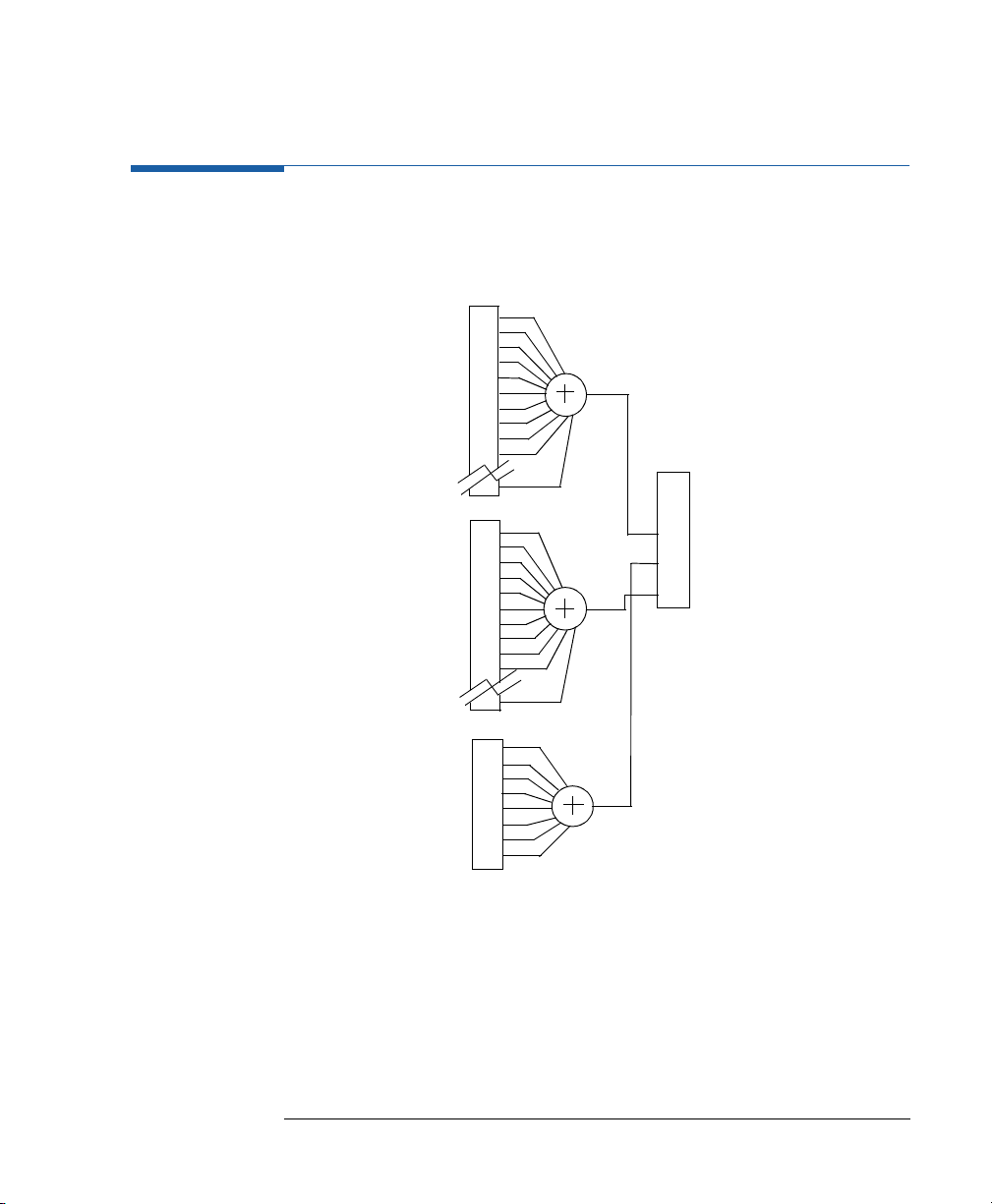
on Use this command to enable or disable channel addition in an instrument
onon
OFF | PLUS
OFF
with two output channels installed. With
from both channels are added at output 1. Output 2 is not used.
This allows you to, for example,
generate 3 and 4 level waveforms,
simulate single or repeated glitches,
generate pulse transitions with a step-change in slew-rate,
simulate overshoot and undershoot.
IMMediate|INTernal[1]
INTernal2
EXTernal1
MANual
CONTINUOUS
TRIGGERED|GATED by PLL
TRIGGERED|GATED by:EXT IN
TRIGGERED|GATED by:MANKey
:CHAN:MATH P LUS
the signals
48
Page 49

Programming Reference
SC
SCPPPPI I
I Innnnssssttttrrrruuuummmmeeeennnnt
SCSC
I II I
t CCCCoooomm
mmaaaannnnd
t t
mmmm
For levels and amplitude values that can be added in the channel
addition mode, refer to chapter 3, Specifications, Levels in Channel
Addition on page 110.
NNNNOOOOTE
TE This functionality is not available for Agilent 81110A with Agilent 81112A
TETE
3.8V/330 MHz outputs installed.
CCCCoooomm
mmaaaannnndddd :CALibration
mmmm
LLLLoooong
ng
ngng
:CALibration[:ALL]
FFFFoooorrrrmmmm Set & Query
PPPPaaaarrrraaaammmmeeeetttteeeerrrr none
****RS
RST
T vvvvaaaalllluuuueeee none
RSRS
T T
DDDDeeeessssccccrrrriiiippppttttiiiion
on Use this command to perform a timing calibration of the instrument.
onon
The timing circuitries for VCO-period, delay and width are calibrated in
reference to the internal PLL reference.
The return values for the query command
:CALibration[:ALL]?
follows:
0 calibration passed
>0 calibration failed
d LLLLiiiisssstttt
d d
are as
When the instrument is switched off and on again, the factory calibration
data are activated again.
49
Page 50

Programming Reference
SC
SCPPPPI I
I Innnnssssttttrrrruuuummmmeeeennnnt
SCSC
I II I
CCCCoooomm
mmaaaannnndddd :DIG:PATT:DATA[1|2|3]
mmmm
LLLLoooong
ng
ngng
t CCCCoooomm
mmaaaannnnd
t t
d LLLLiiiisssstttt
mmmm
d d
:DIGital[:STIMulus]:PATTern:DATA[1|2|3]
FFFFoooorrrrmmmm Set & Query
PPPPaaaarrrraaaammmmeeeetttteeeerrrr
****RS
RST
T vvvvaaaalllluuuueeee
RSRS
T T
[<start>,] <data>
Channel Default
DDDDeeeessssccccrrrriiiippppttttiiiion
on Use this command to set or read the pattern data of one or all channels
onon
[1|2|3] Description Bit 1 Bit 2 Bits 3 to 16384
1 CH1 (OUTPUT 1) 1 0 0
2 CH2 (OUTPUT 2)010
3 STRB(STROBE OUT)100
(8110A: 4096)
starting from Bit 1. The <data> is an arbitrary block of program data as
defined in IEEE 488.2 7.7.6.2, for example:
NNNNOOOOTE
TE Note that the optional <start> parameter is ignored by the instrument if
TETE
you use it
#1541213
# Start of block
1 Length of the length of the data
5 Length of the data
41213 5 bytes of data
#2161000100010001000
# Start of block
2 Length of the length of the data
16 Length of the data
10...00 16 bytes of data
50
Page 51

SC
SCPPPPI I
I Innnnssssttttrrrruuuummmmeeeennnnt
SCSC
I II I
Programming Reference
t CCCCoooomm
mmaaaannnnd
mmmm
d LLLLiiiisssstttt
d d
t t
EEEExxxxaaaammmmpppplllleeeessss
:DIG:PATT:DATA #1541213
The instrument uses each byte of data set one Bit in the pattern memory.
If you don't specify a particular channel, the lowest three bits of each
byte are used to set all three channels, and the top five bits are ignored.
Note that you can therefore use the ASCII characters 0,1,2 and 3, to
program Outputs 1 and 2 in binary with STROBE=0 (or 4,5,6, and 7
for STROBE=1):
DATA
ASCII ignored used
D7 D6 D5 D4 D3 D2 D1 D0
4
1
2
1
3
0 1 1 1 0
0 1 1 1 0
0 1 1 1 0
0 1 1 1 0
0 1 1 1 0
1 0 0
0 0 1
0 1 0
0 0 1
0 1 1
:DIG:PATT:DATA2 #1501011
STRB
STROBE OUT
1
0
0
0
0
CH2
OUTPUT2
0
0
1
0
1
CH1
OUTPUT 1
0
1
0
1
1
If you specify a particular channel, the least significant bit of each byte is
used to set the selected channel, and the top seven bits are ignored. Note
that you can therefore use the ASCII characters `1' and `0' to set
individual bits to 1 and 0:
STRB
STROBE
DATA
ASCII ignored LSB
D7 D6 D5 D4 D3 D2 D1 D0
0
1
0
1
1
0 1 1 1 0 0 0
0 1 1 1 0 0 0
0 1 1 1 0 1 0
0 1 1 1 0 0 0
0 1 1 1 0 0 0
OUT
X
0
X
1
X
0
X
1
X
1
X indicates that the bit remains unchanged.
CH2
OUTPUT2
0
0
1
0
1
CH1
OUTPUT
X
X
X
X
X
51
Page 52

Programming Reference
SC
SCPPPPI I
I Innnnssssttttrrrruuuummmmeeeennnnt
SCSC
I II I
t CCCCoooomm
mmaaaannnnd
t t
mmmm
d LLLLiiiisssstttt
d d
:ARM:SOUR IMM
:DIG:PATT:DATA3 #1501011
:TRIG:COUN 5
:DIG:PATT ON
CCCCoooomm
mmaaaannnndddd :DIG:PATT:PRBS[1|2|3]
mmmm
LLLLoooong
ng
ngng
:DIGital[:STIMulus]:PATTern:PRBS[1|2|3]
FFFFoooorrrrmmmm Set
PPPPaaaarrrraaaammmmeeeetttteeeerrrr <n>,<length>
****RS
RST
T vvvvaaaalllluuuueeee Not applicable
RSRS
T T
SSSSppppeeeecccciiiiffffiiiieeeed
d LLLLiiiimmmmiiiittttssss <n> 7 to 14 (integer) (Agilent 8110A: 7-12)
d d
<length> 2 to 16384 (integer) (Agilent 8110A: 1- 4096)
DDDDeeeessssccccrrrriiiippppttttiiiion
on Use this command to set up PRBS data starting from bit 1. The parameter
onon
<n> is used as the basis to generate a 2
<length> determines how many bits of the PRBS sequence are used. If
<length> is longer than the PRBS, the PRBS is repeated as necessary to
achieve the required length.
EEEExxxxaaaammmmpppplllleeee
To set up a repeating 2
:ARM:SOUR IMM
:TRIG:COUN 1023
:DIG:PATT:PRBS1 10,1023
:DIG:PATT ON
Set continuous mode
Set up pattern data for STROBE channe
Set pattern length (lastbit) to
Switch on PATTERN mode
n
1 PRBS. The parameter
10
1 PRBS on output 1:
Set continuous mode
Set pattern length (last bit) to 1023
Set up PRBS on OUTPUT 1
Switch on PATTERN mode
l
52
Page 53

CCCCoooomm
mmaaaannnndddd :DIG:PATT:PRES[1|2|3]
mmmm
LLLLoooong
ng
ngng
FFFFoooorrrrm
m Set
m m
:DIGital[:STIMulus]:PATTern:PRESet[1|2|3]
PPPPaaaarrrraaaammmmeeeetttteeeerrrr <n>,<length>
****RS
RST
T vvvvaaaalllluuuueeee Not applicable
RSRS
T T
SSSSppppeeeecccciiiiffffiiiieeeed
d LLLLiiiimmmmiiiittttssss <n> 2 to 16384 (integer)
d d
<length> 2 to 16384 (integer)
DDDDeeeessssccccrrrriiiippppttttiiiion
on Use this command to set up clock data starting from bit 1 with value 1.
onon
The parameter <n> is used as the divider to generate a CLOCK÷n
sequence (squarewave if NRZ data is selected). The parameter <length>
determines the length of the sequence.
n=2 Sequence = 101010101010101....
n=3 Sequence = 100100100100100....
n=4 Sequence = 110011001100110....
n=5 Sequence = 110001100011000....
n=6 Sequence = 111000111000111....
n=7 Sequence = 111000011100001....
n=8 Sequence = 111100001111000....
and so on.
SC
SCPPPPI I
I Innnnssssttttrrrruuuummmmeeeennnnt
SCSC
I II I
Programming Reference
t CCCCoooomm
mmaaaannnnd
mmmm
d LLLLiiiisssstttt
d d
t t
Special Case: <n> = 0, <n> = 1,
If <n> = 0 then the sequence defined by <length> is filled with zeros. If
<n> = 1, then the sequence is filled with ones.
EEEExxxxaaaammmmpppplllle
e To set up a CLOCK ÷ 4 squarewave on STROBE OUT:
ee
:TRIG:COUN 4096
:DIG:PATT:PRES3 4,4096
:DIG:PATT ON
NNNNOOOOTE
TE To produce a continuous squarewave the pattern length must be a
TETE
Set pattern length (last bit) to 4096
Set up CLOCK
Switch on PATTERN mode
÷
4 on STRB
multiple of the selected divider, in this case a multiple of 4.
53
Page 54

Programming Reference
SC
SCPPPPI I
I Innnnssssttttrrrruuuummmmeeeennnnt
SCSC
I II I
CCCCoooomm
mmaaaannnndddd :DIG:PATT
mmmm
LLLLoooong
ng
ngng
FFFFoooorrrrmmmm Set & query
PPPPaaaarrrraaaammmmeeeetttteeeerrrr ON | OFF
****RS
RSTTTT OFF
RSRS
DDDDeeeessssccccrrrriiiippppttttiiiion
CCCCoooomm
mmaaaannnndddd :DIG:PATT:UPD
mmmm
LLLLoooong
ng
ngng
FFFFoooorrrrmmmm Set & query
PPPPaaaarrrraaaammmmeeeetttteeeerrrr
****RS
RSTTTT
RSRS
DDDDeeeessssccccrrrriiiippppttttiiiion
t CCCCoooomm
mmaaaannnnd
t t
on Use this command to enable and disable Pattern mode. Use
onon
d LLLLiiiisssstttt
mmmm
d d
:DIGital[:STIMulus]:PATTern[:STATe]
:TRIG:COUN
:DIGital[:STIMulus]:PATTern
ON | OFF | ONCE
ON
on Use this command to enable and disable the automatic updating of the
onon
pattern generating hardware following a
Disable the automatic updating if you want to set up new pattern data in
the instrument without affecting the pattern which is currently being
generated. You can then update the hardware with the new pattern data
by sending a
to program the length of the pattern.
:UPDate
:DIG:PATT:D ATA
:DIG:PATT:UPD ONCE
command.
command.
54
Page 55

CCCCoooomm
mmaaaannnndddd :DIG:SIGN[1|2]:FORM
mmmm
LLLLoooong
ng
ngng
:DIGital[:STIMulus]:SIGNal[1|2]:FORMat
FFFFoooorrrrmmmmaaaatttt Set & Query
PPPPaaaarrrraaaammmmeeeetttteeeerrrr
RRRRaaaannnnge
ge CCCCou
oupppplllliiiing
ge ge
ouou
****RS
RST
T vvvvaaaalllluuuueeee
RSRS
T T
DDDDeeeessssccccrrrriiiippppttttiiiion
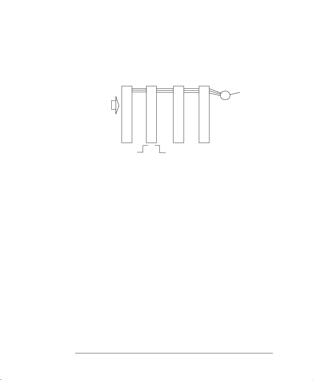
on Use this command to set and read the data format of channels 1 and 2
onon
RZ | NRZ
ng Period, Frequency
ngng
RZ
when using Pattern mode. If you don't specify a channel number in the
command, channel 1 is assumed.
RZ Return to Zero. An RZ pulse is generated for each 1
NRZ Non Return to Zero. A pulse of 100% dutycycle is
Programming Reference
SC
SCPPPPI I
I Innnnssssttttrrrruuuummmmeeeennnnt
SCSC
I II I
t CCCCoooomm
mmaaaannnnd
t t
mmmm
d LLLLiiiisssstttt
d d
in the data. You can vary the width, edges and levels
of the pulse.
generated for each 1 in the data. You can vary the
edges and levels of the pulse.
EEEExxxxaaaammmmpppplllleeee
CCCCoooomm
mmaaaannnndddd :DISP
mmmm
LLLLoooong
ng
ngng
:DIG:SIGN:FORM NRZ
:DISPlay[:WINDow][:STATe]
FFFFoooorrrrmmmm Set & Query
PPPPaaaarrrraaaammmmeeeetttteeeerrrr
****RS
RST
T vvvvaaaalllluuuueeee
RSRS
T T
DDDDeeeessssccccrrrriiiippppttttiiiion
on This command is used to turn the frontpanel display on and off.
onon
ON | OFF | 1 | 0
ON
Switching off the display improves the programming speed of the
instrument.
NNNNOOOOTE
TE *RST switches the display back on. Use
TETE
*RST without switching the display back on.
EEEExxxxaaaammmmpppplllleeee
SECDISP OFF
Set channel 1 data format to NRZ
:SYSTem:PRESet
Switch off the frontpanel display
to perform an
55
Page 56

Programming Reference
SC
SCPPPPI I
I Innnnssssttttrrrruuuummmmeeeennnnt
SCSC
I II I
CCCCoooomm
mmaaaannnndddd :MMEM:CAT?
mmmm
LLLLoooong
ng
ngng
t CCCCoooomm
mmaaaannnnd
t t
d LLLLiiiisssstttt
mmmm
d d
:MMEMory:CATalog?
FFFFoooorrrrmmmm Query
PPPPaaaarrrraaaammmmeeeetttteeeerrrr ["A:"]
****RS
RST
T vvvvaaaalllluuuueeee Not applicable
RSRS
T T
DDDDeeeessssccccrrrriiiippppttttiiiion
on Use this command to get a listing of the contents of the currently
onon
selected directory on the memory card. As there is only one memory card
slot, the parameter A: is optional. The information returned is:
<bytes_used>,<bytes_free>{,<file_entry>}
<bytes_used>
<bytes_free>
<file_entry>
NNNNOOOOTE
TE The <file_type> is always blank. A directory name has <file_size> = 0
TETE
CCCCoooomm
mmaaaannnndddd :MMEM:CDIR
mmmm
LLLLoooong
ng
ngng
:MMEMory:CDIRectory
The total number of bytes used on the memory card.
The total number of bytes still available on the memory card.
String containing the name, type and size of one file:
"<file_name>,<file_type>,<file_size>"
FFFFoooorrrrmmmm Event
PPPPaaaarrrraaaammmmeeeetttteeeerrrr ["directory_name"]
****RS
RST
T vvvvaaaalllluuuueeee Not applicable
RSRS
T T
DDDDeeeessssccccrrrriiiippppttttiiiion
on Use this command to change the current directory on the memory card.
onon
If you don't specify a directory name parameter, the root directory is
selected.
NNNNOOOOTE
TE Note that you cannot use DOS pathnames as directory names, you can
TETE
only select a directory name within the current directory.
Use the directory name ".." to move back to the parent directory of the
current directory, unless you are already in the root directory "\".
EEEExxxxaaaammmmpppplllleeeessss
:MMEM:CDIR
:MMEM:CDIR "PERFORM"
:MMEM:CDIR ".."
Select root directory
Select directory "PERFORM"
Select parent directory
56
Page 57

CCCCoooomm
mmaaaannnndddd :MMEM:COPY
mmmm
LLLLoooong
ng
ngng
:MMEMory:COPY
FFFFoooorrrrmmmm Event
PPPPaaaarrrraaaammmmeeeetttteeeerrrr "filename"[,"A:"],"copyname"[,"A:"]
****RS
RSTTTT Not applicable
RSRS
DDDDeeeessssccccrrrriiiippppttttiiiion
on Use this command to copy an existing file filename in the current
onon
directory to a new file copyname. If copyname is the name of a subdirectory in the current directory, a copy of the file filename is made in
the sub-directory. Use ".." as copyname to copy a file into the parent
directory of the current directory.
EEEExxxxaaaammmmpppplllleeeessss
CCCCoooomm
mmaaaannnndddd :MMEM:DEL
mmmm
LLLLoooong
ng
ngng
:MMEM:COPY "test1","test2"
:MMEM:COPY "test1",".."
:MMEMory:DELete
FFFFoooorrrrmmmm Event
Programming Reference
SC
SCPPPPI I
I Innnnssssttttrrrruuuummmmeeeennnnt
SCSC
I II I
Copy test1 to test2
Copy test1 into parent directory
t CCCCoooomm
mmaaaannnnd
t t
mmmm
d LLLLiiiisssstttt
d d
PPPPaaaarrrraaaammmmeeeetttteeeerrrr "filename"
****RS
RSTTTT Not applicable
RSRS
DDDDeeeessssccccrrrriiiippppttttiiiion
on Use this command to delete file filename from the currently selected
onon
directory.
CCCCoooomm
mmaaaannnndddd :MMEM:INIT
mmmm
LLLLoooong
ng
ngng
:MMEMory:INITialize
FFFFoooorrrrmmmm Event
PPPPaaaarrrraaaammmmeeeetttteeeerrrr ["A:"[,"DOS"]]
****RS
RSTTTT Not applicable
RSRS
DDDDeeeessssccccrrrriiiippppttttiiiion
on Use this command to initialize a memory card to DOS format.
onon
CCCCAAAAUUUUTTTTIIIIOOOONNNN Initializing a memory card destroys any existing data on the card.
57
Page 58

Programming Reference
SC
SCPPPPI I
I Innnnssssttttrrrruuuummmmeeeennnnt
SCSC
I II I
CCCCoooomm
mmaaaannnndddd :MMEM:LOAD:STAT
mmmm
LLLLoooong
ng
ngng
t CCCCoooomm
mmaaaannnnd
t t
d LLLLiiiisssstttt
mmmm
d d
:MMEMory:LOAD:STATe
FFFFoooorrrrmmmm Event
PPPPaaaarrrraaaammmmeeeetttteeeerrrr <n>,"filename"[,"A:"]
****RS
RSTTTT Not applicable
RSRS
SSSSppppeeeecccciiiiffffiiiieeeed
DDDDeeeessssccccrrrriiiippppttttiiiion
d LLLLiiiimmmmiiiittttssss <n> = 0 to 9 (integer)
d d
on Use this command to load a complete instrument setting from file
onon
filename in the current directory into memory <n> in the instrument.
Memories 1 to 9 are the internal memories. Use memory 0 to load a
default setting as the current instrument setting.
EEEExxxxaaaammmmpppplllleeeessss See next command
CCCCoooomm
mmaaaannnndddd :MMEM:STOR:STAT
mmmm
LLLLoooong
ng
ngng
:MMEMory:STORe:STATe
FFFFoooorrrrmmmm Event
PPPPaaaarrrraaaammmmeeeetttteeeerrrr <n>,"filename"[,"A:"]
****RS
RSTTTT Not applicable
RSRS
SSSSppppeeeecccciiiiffffiiiieeeed
DDDDeeeessssccccrrrriiiippppttttiiiion
d LLLLiiiimmmmiiiittttssss <n> = 0 to 9 (integer)
d d
on Use this command to store a complete instrument setting from memory
onon
<n> to file filename in the current directory on the memory card.
Memories 1 to 9 are the internal memories. Use memory 0 to store the
current instrument setting to a file.
EEEExxxxaaaammmmpppplllleeeessss
:MMEM:LOAD:STAT 1,"FREQPERF"
:MMEM:LOAD:STAT 0,"AMPTEST"
:*SAV 2
:*RCL 3
58
Load FREQPERF into memory 1
Load AMPTEST as current setting
Save current setting in memory 2
Recall memory 3 as current setting
Page 59

CCCCoooomm
mmaaaannnndddd :OUTP[1|2]
mmmm
LLLLoooong
ng
ngng
:OUTPut[1|2][:NORMal][:STATe]
FFFFoooorrrrmmmm Set & Query
PPPPaaaarrrraaaammmmeeeetttteeeerrrr ON | OFF | 1 | 0
****RS
RST
T vvvvaaaalllluuuueeee OFF
RSRS
T T
DDDDeeeessssccccrrrriiiippppttttiiiion
EEEExxxxaaaammmmpppplllleeee
CCCCoooomm
LLLLoooong
on Use this command to switch the normal outputs on or off.
onon
:OUTP1 ON
:OUTP2 OFF
mmaaaannnndddd :OUTP[1|2]:COMP
mmmm
ng
ngng
:OUTPut[1|2]:COMPlement[:STATe]
FFFFoooorrrrmmmm Set & Query
PPPPaaaarrrraaaammmmeeeetttteeeerrrr ON | OFF | 1 | 0
****RS
RST
T vvvvaaaalllluuuueeee OFF
RSRS
T T
DDDDeeeessssccccrrrriiiippppttttiiiion
on Use this command to switch the complement/differential outputs on or
onon
off. (Available with Agilent 81112A 3.8 V / 330 MHz output channels)
EEEExxxxaaaammmmpppplllleeee
:OUTP1:COMP ON
:OUTP2:COMP OFF
Programming Reference
SC
SCPPPPI I
I Innnnssssttttrrrruuuummmmeeeennnnt
SCSC
I II I
Switch on output 1
Switch off output 2
Switch on complement output 1
Switch off complement output 2
t CCCCoooomm
mmaaaannnnd
t t
mmmm
d LLLLiiiisssstttt
d d
CCCCoooomm
mmaaaannnndddd :OUTP[1|2]:IMP
mmmm
LLLLoooong
ng
ngng
:OUTPut[1|2]:IMPedance[:INTernal]
FFFFoooorrrrmmmm Set & Query
PPPPaaaarrrraaaammmmeeeetttteeeerrrr Numeric
PPPPaaaarrrraaaammmmeeeetttteeeer
****RS
RST
RSRS
SSSSppppeeeecccciiiiffffiiiieeeed
DDDDeeeessssccccrrrriiiippppttttiiiion
r SSSSuuuuff
r r
T vvvvaaaalllluuuue
T T
d LLLLiiiimmmmiiiitttts
d d
on Use this command to program the source impedance of the output
onon
e 50 Ω
ee
OHM
ffiiiixxxx
ffff
s 50 Ω or 1 kΩ
ss
with engineering prefixes, e.g.:
connectors. Note that only two settings are available. If you try to
program any other value, it will be rounded to one of the specified
values.
MOHM
is Megaohms.
59
Page 60

Programming Reference
SC
SCPPPPI I
I Innnnssssttttrrrruuuummmmeeeennnnt
SCSC
I II I
t CCCCoooomm
mmaaaannnnd
t t
mmmm
d LLLLiiiisssstttt
d d
The Agilent 81112A 3.8V/330 MHz output has a fixed 50 Ω Source
impedance.
EEEExxxxaaaammmmpppplllleeee
CCCCoooomm
mmaaaannnndddd :OUTP[1|2]:IMP:EXT
mmmm
LLLLoooong
ng
ngng
:OUTP1:IMP 50OHM
:OUTP2:IMP 1000OHM
:OUTPut[1|2]:IMPedance:EXTernal
FFFFoooorrrrmmmm Set & Query
PPPPaaaarrrraaaammmmeeeetttteeeerrrr Numeric
PPPPaaaarrrraaaammmmeeeetttteeeer
****RS
RST
RSRS
SSSSppppeeeecccciiiiffffiiiieeeed
DDDDeeeessssccccrrrriiiippppttttiiiion
r SSSSuuuuff
r r
T vvvvaaaalllluuuue
T T
d LLLLiiiimmmmiiiitttts
d d
on Use this command to set the expected load impedance of the device-
onon
e 50.0 Ω
ee
OHM
ffiiiixxxx
ffff
s 0.1 Ω to 1 MΩ
ss
with engineering prefixes, e.g.:
under-test at the output connectors. If you have a non-50 Ω load, the
output levels at the device-under-test will not be the levels you program
or set via the frontpanel unless you set the expected load using this
command. With the Agilent 81112A 3.8V/330MHz output channels it is not
possible to set load impedance, it expects 50 Ω loads.
EEEExxxxaaaammmmpppplllleeee
:OUTP1:IMP:EXT 47.6OHM
:OUTP2:IMP:EXT 1M OHMS
Set output 1 impedance to 500
Set output 2 impedance to 1 k
MOHM
is Megaohms.
Set load impedance at OUTPUT 1 to 47.6Ω
Set load impedance at OUTPUT 2 to 1 M
Ω
Ω
Ω
CCCCoooomm
mmaaaannnndddd :OUTP[1|2]:POL
mmmm
LLLLoooong
ng
ngng
:OUTPut[1|2]:POLarity
FFFFoooorrrrmmmm Set & Query
PPPPaaaarrrraaaammmmeeeetttteeeerrrr NORMal | INVerted
****RS
RST
T vvvvaaaalllluuuueeee NORM
RSRS
T T
DDDDeeeessssccccrrrriiiippppttttiiiion
EEEExxxxaaaammmmpppplllleeee
on Use this command to invert the signal at the outputs.
onon
:OUTP1:POL INV
:OUTP1:POL NORM
60
Inverted signal at output1
Normal signal at output 1
Page 61

CCCCoooomm
mmaaaannnndddd :CURR[1|2]
mmmm
LLLLoooong
ng
ngng
[:SOURce]:CURRent[1|2][:LEVel][:IMMediate][:AMPLitude]
FFFFoooorrrrmmmm Set & Query
PPPPaaaarrrraaaammmmeeeetttteeeerrrr Numeric
SC
SCPPPPI I
I Innnnssssttttrrrruuuummmmeeeennnnt
SCSC
I II I
Programming Reference
t CCCCoooomm
mmaaaannnnd
mmmm
d LLLLiiiisssstttt
d d
t t
PPPPaaaarrrraaaammmmeeeetttteeeer
****RS
RST
RSRS
SSSSppppeeeecccciiiiffffiiiieeeed
VVVVaaaallllue co
RRRRaaaannnnge c
DDDDeeeessssccccrrrriiiippppttttiiiion
r ssssuuuuff
r r
T vvvvaaaalllluuuue
T T
d LLLLiiiimmmmiiiittttssss 10 V Outputs (from high Z into short): max 400 mA typical
d d
ue couuuupppplllliiiinnnngggg
ue coue co
ge cooooup
uplllliiiinnnngggg Offset
ge cge c
upup
on This command programs the amplitude current of the output signal. Note
onon
EEEExxxxaaaammmmpppplllleeee
ffiiiixxxxA with engineering prefixes.
ffff
e 20 mA (50 Ω into 50 Ω)
ee
3.8V Outputs (50 Ω into short): max 152 mA typical
Amplitude = High - Low
Offset =
that to set the output levels in terms of current, you first have to execute
[:SOURce]:HO LD CURRen t
the
[:SOURce]:CURRent
The available current range is limited by the combination of:
Specified voltage limits
Actual output impedance setting
Actual expected load impedance setting:
:OUTPut:IMPedance:EXTernal
:HOLD CURR
:CURR1 75MA
High - Low
2
command to enable the
subsystem.
:OUTPut:IMPedance
Enable CURRENT subsystem
Set output 1 amplitude to 75 mA
61
Page 62

Programming Reference
SC
SCPPPPI I
I Innnnssssttttrrrruuuummmmeeeennnnt
SCSC
I II I
CCCCoooomm
mmaaaannnndddd :CURR[1|2]:OFFSet
mmmm
LLLLoooong
ng
ngng
t CCCCoooomm
mmaaaannnnd
t t
d LLLLiiiisssstttt
mmmm
d d
[:SOURce]:CURRent[1|2][:LEVel][:IMMediate]:OFFSet
FFFFoooorrrrmmmm Set & Query
PPPPaaaarrrraaaammmmeeeetttteeeerrrr Numeric
PPPPaaaarrrraaaammmmeeeetttteeeer
****RS
RST
RSRS
VVVVaaaallllue co
RRRRaaaannnnge c
DDDDeeeessssccccrrrriiiippppttttiiiion
r ssssuuuuff
r r
T vvvvaaaalllluuuue
T T
ue couuuupppplllliiiinnnngggg
ue coue co
ge cooooup
uplllliiiinnnngggg Amplitude
ge cge c
upup
on This command programs the offset current of the output signal. Note that
onon
EEEExxxxaaaammmmpppplllleeee
ffiiiixxxxA with engineering prefixes.
ffff
e 0.0 µA (50 Ω into 50 Ω)
ee
Amplitude = High - Low
Offset =
to set the output levels in terms of current, you first have to execute the
[:SOURce]:HOLD CURRent
:SOURce]:CURRent
The available current range is limited by the combination of:
Specified voltage limits
Actual output impedance setting
Actual expected load impedance setting
:HOLD CURR
:CURR1:OFF 50MA
High - Low
subsystem.
2
command to enable the
:OUTPut:IMPedance
Enable CURRENT subsystem
Set output 1 offset to 50 mA
62
Page 63

CCCCoooomm
mmaaaannnndddd :CURR[1|2]:HIGH
mmmm
LLLLoooong
ng
ngng
[:SOURce]:CURRent[1|2][:LEVel][:IMMediate]:HIGH
FFFFoooorrrrmmmm Set & Query
PPPPaaaarrrraaaammmmeeeetttteeeerrrr Numeric
SC
SCPPPPI I
I Innnnssssttttrrrruuuummmmeeeennnnt
SCSC
I II I
Programming Reference
t CCCCoooomm
mmaaaannnnd
mmmm
d LLLLiiiisssstttt
d d
t t
PPPPaaaarrrraaaammmmeeeetttteeeer
VVVVaaaallllue co
RRRRaaaannnnge c
****RS
RST
RSRS
SSSSppppeeeecccciiiiffffiiiieeeed
DDDDeeeessssccccrrrriiiippppttttiiiion
EEEExxxxaaaammmmpppplllle
r ssssuuuuff
r r
ue couuuupppplllliiiinnnngggg
ue coue co
ge cooooup
uplllliiiinnnngggg Low-level
ge cge c
upup
T vvvvaaaalllluuuue
T T
d LLLLiiiimmmmiiiitttts
d d
on This command programs the high-level current of the output signal. Note
onon
e
e e
ffiiiixxxx A with engineering prefixes.
ffff
Amplitude = High - Low
Offset =
High - Low
2
e +10 mA (50 Ω into 50 Ω)
ee
s 10 V Output (from high Z into short): 396 mA to 400 mA typical
s s
3.8 V (from 50 Ω into short): 82 mA to 152 mA typical
that to set the output levels in terms of current, you first have to execute
[:SOURCE]:HOLD CURRent
[:SOURCE]:CURRent
subsystem.
The available current range is limited by the combination of:
Specified voltage limits
Actual output impedance setting
Actual expected load impedance setting:
:OUTPut:IMPedance:EXTernal
:HOLD CURR"
:CURR1:HIGH 150MA
command to enable the
:OUTPut:IMPedance
Enable CURRENT subsystem
Set output 1 high-level to 150 mA
63
Page 64

Programming Reference
SC
SCPPPPI I
I Innnnssssttttrrrruuuummmmeeeennnnt
SCSC
I II I
CCCCoooomm
mmaaaannnndddd :CURR[1|2]:LOW
mmmm
LLLLoooong
ng
ngng
t CCCCoooomm
mmaaaannnnd
t t
d LLLLiiiisssstttt
mmmm
d d
[:SOURce]:CURRent[1|2][:LEVel][:IMMediate]:LOW
FFFFoooorrrrmmmm Set & Query
PPPPaaaarrrraaaammmmeeeetttteeeerrrr Numeric
PPPPaaaarrrraaaammmmeeeetttteeeer
VVVVaaaallllue co
RRRRaaaannnnge c
****RS
RST
RSRS
SSSSppppeeeecccciiiiffffiiiieeeed
DDDDeeeessssccccrrrriiiippppttttiiiion
EEEExxxxaaaammmmpppplllle
r ssssuuuuff
r r
ue couuuupppplllliiiinnnngggg
ue coue co
ge cooooup
uplllliiiinnnngggg High-level
ge cge c
upup
T vvvvaaaalllluuuue
e 10 mA (50 Ω into 50 Ω)
T T
ee
d LLLLiiiimmmmiiiittttssss 10 V Outputs (from high Z into short): 400 mA to 396 mA typical
d d
on This command programs the low-level current of the output signal. Note
onon
e
e e
ffiiiixxxx A with engineering prefixes.
ffff
Amplitude = High - Low
Offset =
3.8 V Outputs (from 50 Ω into short): 84 mA to 150 mA typical
that to set the output levels in terms of current, you first have to execute
[:SOURce]:HO LD CURR ent c
the
[:SOURce]:CURRent
The available current range is limited by the combination of:
Specified voltage limits
Actual output Impedance setting
Actual expected load impedance setting:
:OUTPUT:IMPedance:EXTernal
:HOLD CURR
:CURR1:LOW 50 MA
High - Low
2
ommand to enable the
subsystem.
:OUTPut:IMPedance
Enable CURRENT subsystem
Set output 1 low-level to 50 mA
64
Page 65

CCCCoooomm
mmaaaannnndddd :CURR[1|2]:LIM
mmmm
LLLLoooong
ng
ngng
[:SOURce]:CURRent[1|2]:LIMit[:HIGH]
FFFFoooorrrrmmmm Set & Query
PPPPaaaarrrraaaammmmeeeetttteeeerrrr Numeric
SC
SCPPPPI I
I Innnnssssttttrrrruuuummmmeeeennnnt
SCSC
I II I
Programming Reference
t CCCCoooomm
mmaaaannnnd
mmmm
d LLLLiiiisssstttt
d d
t t
PPPPaaaarrrraaaammmmeeeetttteeeer
****RS
RST
RSRS
DDDDeeeessssccccrrrriiiippppttttiiiion
r ssssuuuuff
ffiiiixxxxA with engineering prefixes.
r r
ffff
T vvvvaaaalllluuuueeee +10.0 mA
T T
on Use this command to set/read the High-level current limit. If you switch
onon
on current limiting, the High-level current cannot be set above the
programmed limit.
NNNNOOOOTE
TE The current is NOT limited by the OUTPUT hardware, this is a software
TETE
limit.
EEEExxxxaaaammmmpppplllleeee
CCCCoooomm
mmaaaannnndddd :CURR[1|2]:LIM:LOW
mmmm
LLLLoooong
ng
ngng
:HOLD CURR
:CURR1:LIM 50 MA
:CURR1:LIM:STAT ON
[:SOURce]:CURRent[1|2]:LIMit:LOW
Enable CURRENT subsystem
Set output 1 high-level current limit to 50 m
Switch on output 1 limits
FFFFoooorrrrmmmm Set & Query
PPPPaaaarrrraaaammmmeeeetttteeeerrrr Numeric
PPPPaaaarrrraaaammmmeeeetttteeeer
****RS
RST
RSRS
DDDDeeeessssccccrrrriiiippppttttiiiion
r ssssuuuuff
ffiiiixxxxA with engineering prefixes.
r r
ffff
T vvvvaaaalllluuuueeee 10.0 mA
T T
on Use this command to set/read the Low-level current limit. If you switch
onon
on current limiting, the Low-level current cannot be set below the
programmed limit.
A
NNNNOOOOTE
TE The current is not limited by the output hardware, this is a software limit.
TETE
EEEExxxxaaaammmmpppplllleeee
:HOLD CURR
:CURR1:LIM:LOW -50MA*
:CURR1:LIM:STAT ON
Enable CURRENT subsystem
Set output 1 low-level current limit
to 50 mA
Switch on output 1 limits
65
Page 66

Programming Reference
SC
SCPPPPI I
I Innnnssssttttrrrruuuummmmeeeennnnt
SCSC
I II I
CCCCoooomm
mmaaaannnndddd :CURR[1|2]:LIM:STAT
mmmm
LLLLoooong
ng
ngng
t CCCCoooomm
mmaaaannnnd
t t
d LLLLiiiisssstttt
mmmm
d d
[:SOURce]:CURRent[1|2]:LIMit:STATe
FFFFoooorrrrmmmm Set & Query
PPPPaaaarrrraaaammmmeeeetttteeeerrrr
****RS
RST
T vvvvaaaalllluuuueeee
RSRS
T T
DDDDeeeessssccccrrrriiiippppttttiiiion
on This command switches the output limits on or off. When you switch on
onon
ON | OFF | 1 | 0
OFF
the output limits cannot program the output-levels beyond the
programmed limits, until you switch off the output limits. The limits
apply whether you program high/low levels or amplitude/offset levels.
NNNNOOOOTE
TE You can switch the limits on and off in both the
TETE
and the
[:SOURce]:VOLTage
subsystems but the current and voltage
limits are not enabled/disabled independently. The voltage and current
limits are always enabled/disabled together.
EEEExxxxaaaammmmpppplllleeee
CCCCoooomm
mmaaaannnndddd :FREQ
mmmm
LLLLoooong
ng
ngng
:HOLD CURR
:CURR1:LIM 50MA
:CURR1:LIM:LOW -50MA
:CURR1:LIM:STAT ON
[:SOURce]:FREQuency[:CW|:FIXed]
Enable CURRENT subsystem
Set output 1 high-level current limit
to 50 mA
Set output 1 low-level current limit
to 50mA
Switch on output 1 limits
FFFFoooorrrrmmmm Set & Query
PPPPaaaarrrraaaammmmeeeetttteeeerrrr Numeric
PPPPaaaarrrraaaammmmeeeetttteeeer
VVVVaaaallllue co
****RS
RST
RSRS
r SSSSuuuuff
r r
ue couuuupppplllliiiinnnngggg
ue coue co
T vvvvaaaalllluuuueeee 1.00 MHz
T T
ffiiiixxxx
ffff
Hz
with engineering prefixes, or
Period =
1
Frequency
MHZ
for Megahertz.
[:SOURce]:CURRent
66
Page 67

SC
SCPPPPI I
I Innnnssssttttrrrruuuummmmeeeennnnt
SCSC
I II I
Programming Reference
t CCCCoooomm
mmaaaannnnd
mmmm
d LLLLiiiisssstttt
d d
t t
SSSSppppeeeecccciiiiffffiiiieeeed
DDDDeeeessssccccrrrriiiippppttttiiiion
d lllliiiimmmmiiiittttssss Consider the following limits for the individual output modules
d d
Agilent 81111A Agilent 81112A Agilent 81105A Agilent 8110A
1 MHz to 165 MHz 1 MHz to 330 MHz 1 MHz to 80 MHz VCO 1Hz to 150 MHz
on Use this command to set/read the pulse frequency. Select the frequency
onon
source for the pulse frequency using :TRIGger:SOURce. The currently
selected source is programmed by this command. Note that the specified
limits and available resolution depend on the selected source.
You cannot set the pulse frequency if you have selected the CLK IN
connector as the frequency source (:TRIG:SOUR EXT2).
EEEExxxxaaaammmmpppplllleeee
CCCCoooomm
mmaaaannnndddd :FREQ:AUTO
mmmm
LLLLoooong
ng
ngng
:TRIG:SOUR INT
:FREQ 75MHz
[:SOURce]:FREQuency[:CW|:FIXed]:AUTO
FFFFoooorrrrmmmm Event
PPPPaaaarrrraaaammmmeeeetttteeeerrrr ONCE
****RS
RST
T vvvvaaaalllluuuueeee Not applicable
RSRS
T T
DDDDeeeessssccccrrrriiiippppttttiiiion
on Use this command to measure the frequency at the CLK IN connector. If
onon
the CLK IN connector is the selected pulse frequency source, you can
then read the measured value with :FREQ?
EEEExxxxaaaammmmpppplllleeee
:TRIG:SOUR EXT2
:FREQ:AUTO ONCE
:FREQ?
PLL 1 MHz to 150 MHz
Select internal osc. as pulse trigger
Set pulse frequency to 75 MHz
Select ext CLK IN as pulse trigger
Measure frequency at CLK IN
Query pulse frequency
67
Page 68

Programming Reference
SC
SCPPPPI I
I Innnnssssttttrrrruuuummmmeeeennnnt
SCSC
I II I
CCCCoooomm
mmaaaannnndddd :HOLD
mmmm
LLLLoooong
ng
ngng
FFFFoooorrrrmmmm Set & Query
PPPPaaaarrrraaaammmmeeeetttteeeerrrr
****RS
RST
T vvvvaaaalllluuuueeee
RSRS
T T
DDDDeeeessssccccrrrriiiippppttttiiiion
CCCCoooomm
mmaaaannnndddd :PHAS[1|2]
mmmm
LLLLoooong
ng
ngng
FFFFoooorrrrmmmm Set & Query
PPPPaaaarrrraaaammmmeeeetttteeeerrrr Numeric
PPPPaaaarrrraaaammmmeeeetttteeeer
FFFFuuuunc
ncttttiiiion
onaaaal
ncnc
onon
ccccou
oupppplllliiiing
ng
ouou
ngng
t CCCCoooomm
mmaaaannnnd
t t
on Use this command to enable either of the
onon
r ssssuuuuff
ffiiiixxxx
r r
ffff
l
l l
d LLLLiiiisssstttt
mmmm
d d
[:SOURce]:HOLD
VOLTage | CURRent
VOLT
[:SOURce]:CURRent
You can control the signal levels of the instrument outputs in terms of
voltage or current.
[:SOURce]:PHASe[1|2][:ADJust]
DEG
RAD
oooor
r
r r
Programming the pulse phase also executes
PHASe
so that the pulse phase is held constant when the signal frequency
is changed.
[:SOURce]:VOLTage
subsystems.
. A parameter without a suffix is interpreted as
[:SOURce]:PULSe:HOLD
RAD
or
.
VVVVaaaallllue co
ue couuuupppplllliiiinnnngggg
ue coue co
****RS
RST
T vvvvaaaalllluuuueeee 0.0
RSRS
T T
SSSSppppeeeecccciiiiffffiiiieeeed
DDDDeeeessssccccrrrriiiippppttttiiiion
d lllliiiimmmmiiiitttts
d d
on Use this command to set/read the relative phase delay of the output
onon
Phase
×
elay =
360
s 0 to 360° constrained by delay and period limits.
ss
signal. This is equivalent to setting an absolute or percentage pulse delay
[:SOURce]:PULSe:DELay
with
If you want the phase delay to remain constant when the pulse period is
varied (rather than the absolute pulse delay) use
[:SOURce]:PULSe:DELay[1|2]:HOLD PRATio
68
Period
.
.
Page 69

SC
SCPPPPI I
I Innnnssssttttrrrruuuummmmeeeennnnt
SCSC
I II I
Programming Reference
t CCCCoooomm
mmaaaannnnd
mmmm
d LLLLiiiisssstttt
d d
t t
EEEExxxxaaaammmmpppplllleeee
CCCCoooomm
mmaaaannnndddd :PULS:DCYC[1|2]
mmmm
LLLLoooong
ng
ngng
:PULS:DEL1 500NS
:PHAS2 180 DEG
:PULS:DEL1:HOLD TIM
:PULS:DEL2:HOLD PRAT
[:SOURce]:PULSe:DCYCle[1|2]
FFFFoooorrrrmmmm Set & Query
PPPPaaaarrrraaaammmmeeeetttteeeerrrr Numeric
VVVVaaaallllue co
ue couuuupppplllliiiinnnngggg
ue coue co
Width =
Dutycycle
100
****RS
RST
T vvvvaaaalllluuuueeee 10.0% (derived from Width and Period)
RSRS
T T
SSSSppppeeeecccciiiiffffiiiieeeed
DDDDeeeessssccccrrrriiiippppttttiiiion
EEEExxxxaaaammmmpppplllle
d lllliiiimmmmiiiittttssss 0.001% 99.9%, depends on width, transition and period.
d d
on Use this command to program the dutycycle of the pulse signal. If you
onon
want to set an absolute pulse width use
[:SOURce]:PULSe:WIDTh[1|2]
If you want the pulse dutycycle to remain constant when the pulse period
is varied (rather than the absolute pulse width), use
:SOURce]:PULSe:HOLD[1|2] DCYCle
e
e e
:PULS:DCYC1 25PCT
:PULS:HOLD1 DCYC
Set output 1 delay to 500ns
Set output 2 phase to 180
Hold output 1 delay constant with varying
period
Hold output 2 phase constant with varying period
Period
×
°
.
Set output 1 dutycycle to 25%
Hold dutycycle constant with varying period
69
Page 70

Programming Reference
SC
SCPPPPI I
I Innnnssssttttrrrruuuummmmeeeennnnt
SCSC
I II I
CCCCoooomm
mmaaaannnndddd :PULS:DEL[1|2]
mmmm
LLLLoooong
ng
ngng
t CCCCoooomm
mmaaaannnnd
t t
d LLLLiiiisssstttt
mmmm
d d
[:SOURce]:PULSe:DELay[1|2]
FFFFoooorrrrmmmm Set & Query
PPPPaaaarrrraaaammmmeeeetttteeeerrrr Numeric
PPPPaaaarrrraaaammmmeeeetttteeeer
VVVVaaaallllue co
****RS
RST
RSRS
SSSSppppeeeecccciiiiffffiiiieeeed
DDDDeeeessssccccrrrriiiippppttttiiiion
EEEExxxxaaaammmmpppplllle
r ssssuuuuff
r r
ue couuuupppplllliiiinnnngggg
ue coue co
T vvvvaaaalllluuuueeee 0.0
T T
d lllliiiimmmmiiiittttssss 0.00 ns to 999 s (limited by period and minimum width)
d d
on Use this command to set/read the pulse delay. Delay is the time between
onon
e
e e
ffiiiixxxxS with engineering prefixes. You can change the default unit using
ffff
[:SOURce]:PULSe:DELay[1|2]:UNIT.
Phase =
Delay
360
×
Period
Delay% =
Agilent 81111A Agilent 81112A Agilent 81105A Agilent 8110A
3.03 ns 3.03 ns 12.5 ns 6.65 ns
the start of the pulse period and the start of the leading edge of the pulse.
If you want the pulse delay to remain constant when the pulse period is
varied (rather than the phase delay) use
[:SOURce]:PULSe:DELay[1|2]:HOLD TIME.
:PULS:DEL1 500NS
:PHAS2 180 DEG
:PULS:DEL1:HOLD TIME
:PULS:DEL2:HOLD PRAT
Delay
Period
100
×
Set output1 delay to500 ns
Set output 2 phase to180
Hold output 1 delay constant with varying
period
Hold OUTPUT 2 phase constant with varying
period
°
70
Page 71

CCCCoooomm
mmaaaannnndddd :PULS:DEL[1|2]:HOLD
mmmm
LLLLoooong
ng
ngng
[:SOURce]:PULSe:DELay[1|2]:HOLD
FFFFoooorrrrmmmm Set & Query
PPPPaaaarrrraaaammmmeeeetttteeeerrrr
****RS
RST
T vvvvaaaalllluuuueeee
RSRS
T T
DDDDeeeessssccccrrrriiiippppttttiiiion
on Use this command to set/read the coupling between the pulse period and
onon
TIME
TIME
PRATio
|
the pulse delay:
TIME The absolute pulse delay is held fixed when the
PRATio The pulse phase delay (delay as ratio of period) is
Programming Reference
SC
SCPPPPI I
I Innnnssssttttrrrruuuummmmeeeennnnt
SCSC
I II I
t CCCCoooomm
mmaaaannnnd
t t
mmmm
d LLLLiiiisssstttt
d d
pulse period is varied (Pulse phase varies).
held fixed when the pulse period is varied (Pulse
delay varies.
EEEExxxxaaaammmmpppplllleeee
CCCCoooomm
mmaaaannnndddd :PULS:DEL[1|2]:UNIT
mmmm
LLLLoooong
ng
ngng
:PULS:DEL1 500ns
:PHAS2 180DEG
:PULS:DEL1:HOLD TIME
:PULS:DEL2:HOLD PRAT
[:SOURce]:PULSe:DELay[1|2]:UNIT
FFFFoooorrrrmmmm Set & Query
PPPPaaaarrrraaaammmmeeeetttteeeerrrr
****RS
RST
T vvvvaaaalllluuuueeee
RSRS
T T
DDDDeeeessssccccrrrriiiippppttttiiiion
on Use this command to set/read the default units for the pulse-delay
onon
S | SEC | PCT | DEG | RAD
S
parameter. The default unit of a parameter is the unit used when the
parameter is programmed to a value without a unit suffix.
EEEExxxxaaaammmmpppplllleeee
:PULS:DEL1:UNIT PCT
:PULS:DEL1 50
Set output 1 delay to 500ns
Set output 2 phase to 180
Hold output 1 delay constant with varying
period
Hold output 2 phase constant with varying
period
Set output 1 delay unit to %
Set output 1 delay to 50% of period
°
71
Page 72

Programming Reference
SC
SCPPPPI I
I Innnnssssttttrrrruuuummmmeeeennnnt
SCSC
I II I
CCCCoooomm
mmaaaannnndddd :PULS:DOUB[1|2]
mmmm
LLLLoooong
ng
ngng
t CCCCoooomm
mmaaaannnnd
t t
d LLLLiiiisssstttt
mmmm
d d
[:SOURce]:PULSe:DOUBle[1|2][:STATe]
FFFFoooorrrrmmmm Set & Query
PPPPaaaarrrraaaammmmeeeetttteeeerrrr
****RS
RST
T vvvvaaaalllluuuueeee
RSRS
T T
DDDDeeeessssccccrrrriiiippppttttiiiion
on Use this command to switch double-pulse mode on or off. In double-
onon
OFF | ON
OFF
pulse mode two pulses are generated per pulse period and the delay
between the leading edges of the first and second pulse can be adjusted.
CCCCoooomm
mmaaaannnndddd :PULS:DOUB[1|2]:DEL
mmmm
LLLLoooong
ng
ngng
[:SOURce]:PULSe:DOUBle[1|2]:DELay
FFFFoooorrrrmmmm Set & Query
PPPPaaaarrrraaaammmmeeeetttteeeerrrr Numeric
PPPPaaaarrrraaaammmmeeeetttteeeer
VVVVaaaallllue co
****RS
RST
RSRS
SSSSppppeeeecccciiiiffffiiiieeeed
DDDDeeeessssccccrrrriiiippppttttiiiion
r ssssuuuuff
r r
ue couuuupppplllliiiinnnngggg
ue coue co
T vvvvaaaalllluuuueeee 0.0
T T
d lllliiiimmmmiiiittttssss Consider the following limits for the individual output modules:
d d
on Use this command to set/read the delay between the leading edges of the
onon
ffiiiixxxxS with engineering prefixes. You can change the default unit using
ffff
[:SOURce]:PULSe:DOUBle:DELay[1|2]:UNIT.
DblDel% =
DblDel
× 100
Period
Agilent 81104A
with 81105A
12.5 ns to 999.5 s
(period width
6.25 ns)
min period
25 ns
two pulses in double-pulse mode. The first pulse always starts at the start
of the pulse period.
72
Agilent 81110A
with 81111A
6.06 ns to 999.5 s
(period width
3.03 ns)
min period
12.2 ns
Agilent 81110A
with 81112A Agilent 8110A
3.03 ns to 999.5 s
(period width
1.5 ns)
min period
6.06 ns
6.65 ns to 999 ms
(limited by period
width 6.65 ns)
min period
13.3 ns
Page 73

If you want the double-delay to remain constant when the pulse period is
varied (rather than the double-delay as percentage of period) use
[:SOURce]:PULSe:DOUBle[1|2]:DELay:HOLD TIME.
EEEExxxxaaaammmmpppplllleeee
CCCCoooomm
mmaaaannnndddd :PULS:DOUB[1|2]:DEL:HOLD
mmmm
LLLLoooong
ng
ngng
:PULS:DOUB1 ON
:PULS:DOUB1:DEL 500NS
:PULS:DOUB1:DEL:HOLD TIME
[:SOURce]:PULSe:DOUBle[1|2]:DELay:HOLD
FFFFoooorrrrmmmm Set & Query
PPPPaaaarrrraaaammmmeeeetttteeeerrrr TIME|PRATio
****RS
RST
T vvvvaaaalllluuuueeee TIME
RSRS
T T
DDDDeeeessssccccrrrriiiippppttttiiiion
on Use this command to set/read the coupling between the pulse period and
onon
the double-pulse delay:
TIME The absolute double-pulse delay is held fixed when the
pulse period is varied.
Programming Reference
SC
SCPPPPI I
I Innnnssssttttrrrruuuummmmeeeennnnt
SCSC
I II I
Switch on Double pulses on output 1
Set inter-pulse delay to 500ns
Hold inter-pulse delay fixed with varying
pulse period
t CCCCoooomm
mmaaaannnnd
t t
mmmm
d LLLLiiiisssstttt
d d
EEEExxxxaaaammmmpppplllleeee
PRATio The double-pulse delay as percentage of period is held
fixed when the pulse period is varied.
:PULS:DOUB1 ON
:PULS:DOUB1:DEL 50 PCT
:PULS:DOUB1:DEL:HOLD PRAT
Switch on Double pulses on output 1
Set inter-pulse delay to 50% of pulseperiod
Hold inter-pulse delay as fixed percentage
of pulse period
73
Page 74

Programming Reference
SC
SCPPPPI I
I Innnnssssttttrrrruuuummmmeeeennnnt
SCSC
I II I
CCCCoooomm
mmaaaannnndddd :PULS:DOUB[1|2]:DEL:UNIT
mmmm
LLLLoooong
ng
ngng
t CCCCoooomm
mmaaaannnnd
t t
d LLLLiiiisssstttt
mmmm
d d
[:SOURce]:PULSe:DOUBle[1|2]:DELay:UNIT
FFFFoooorrrrmmmm Set & Query
PPPPaaaarrrraaaammmmeeeetttteeeerrrr
****RS
RST
T vvvvaaaalllluuuueeee
RSRS
T T
DDDDeeeessssccccrrrriiiippppttttiiiion
on Use this command to set/read the default units for the double-delay
onon
S | SEC | PCT
S
parameter. The default unit of a parameter is the unit used when the
parameter is programmed to a value without a unit suffix.
EEEExxxxaaaammmmpppplllleeee
CCCCoooomm
mmaaaannnndddd :PULS:HOLD[1|2]
mmmm
LLLLoooong
ng
ngng
:PULS:DOUB1:DEL:UNIT PCT"
:PULS:DOUB1:DEL 50
[:SOURce]:PULSe:HOLD[1|2]
FFFFoooorrrrmmmm Set & Query
PPPPaaaarrrraaaammmmeeeetttteeeerrrr
****RS
RST
T vvvvaaaalllluuuueeee
RSRS
T T
DDDDeeeessssccccrrrriiiippppttttiiiion
on Use this command to set whether the pulse width, the pulse-dutycycle or
onon
WIDTh | DCYCle | TDELay
WIDTh
the pulse-trailing-edge delay is held constant when the pulse period is
changed.
EEEExxxxaaaammmmpppplllleeee
:PULS:DEL:HOLD1 TIME
:PULS:DEL 20NS
:PULS:HOLD1 DCYC
:PULS:DCYC 25PCT
Set output 1 double-delay unit to %
Set output 1 inter-pulse delay to 50%
of period
Hold output 1 delay fixed when frequency
varies
Set output 1 delay to 20ns
Hold output 1 dutycycle fixed when
frequency varies
Set output 1 dutycycle to 25%
74
Page 75

CCCCoooomm
mmaaaannnndddd :PULS:PER
mmmm
LLLLoooong
ng
ngng
[:SOURce]:PULSe:PERiod
FFFFoooorrrrmmmm Set & Query
PPPPaaaarrrraaaammmmeeeetttteeeerrrr Numeric
SC
SCPPPPI I
I Innnnssssttttrrrruuuummmmeeeennnnt
SCSC
I II I
Programming Reference
t CCCCoooomm
mmaaaannnnd
mmmm
d LLLLiiiisssstttt
d d
t t
PPPPaaaarrrraaaammmmeeeetttteeeer
VVVVaaaallllue co
****RS
RST
RSRS
SSSSppppeeeecccciiiiffffiiiieeeed
DDDDeeeessssccccrrrriiiippppttttiiiion
r SSSSuuuuff
r r
ue couuuupppplllliiiinnnngggg
ue coue co
T vvvvaaaalllluuuue
T T
d lllliiiimmmmiiiittttssss Consider the following limits for the individual output modules:
d d
on Use this command to set/read the pulse period. Select the pulse-period
onon
EEEExxxxaaaammmmpppplllleeee
ffiiiixxxxS with engineering prefixes.
ffff
Frequency =
e 1 µs
ee
Agilent 81104A
with 81105A
12.5 ns to 999.5 s 6.06 ns to 999.5 s 3.03 ns to 999.5 s VCO: 6.65 ns to 999 ms
source using
programmed by this command. Note that the specified limits and
available resolution depend on the selected source.
You cannot set the pulse period if you have selected the CLK IN
connector as the frequency source (
:TRIG:SOUR INT
:PULS:PER 25NS
Agilent 81110A
with 81111A
:TRIGger:SOURce
1
Period
Agilent 81110A
with 81112A Agilent 8110A
PLL: 6.650 ns to 999.0 s
. The currently selected source is
:TRIG:SOUR E XT2
Select internal osc. as pulse trigger
Set pulse frequency to 25 ns
).
75
Page 76

Programming Reference
SC
SCPPPPI I
I Innnnssssttttrrrruuuummmmeeeennnnt
SCSC
I II I
CCCCoooomm
mmaaaannnndddd :PULS:PER:AUTO
mmmm
LLLLoooong
ng
ngng
t CCCCoooomm
mmaaaannnnd
t t
d LLLLiiiisssstttt
mmmm
d d
[:SOURce]:PULSe:PERiod:AUTO
FFFFoooorrrrmmmm Event
PPPPaaaarrrraaaammmmeeeetttteeeerrrr ONCE
****RS
RST
T vvvvaaaalllluuuueeee Not applicable
RSRS
T T
DDDDeeeessssccccrrrriiiippppttttiiiion
on Use this command to measure the period at the CLK IN connector. If the
onon
CLK IN connector is the selected pulse-period source, you can then read
the measured value with
EEEExxxxaaaammmmpppplllleeee
CCCCoooomm
mmaaaannnndddd :PULS:TDEL[1|2]
mmmm
LLLLoooong
ng
ngng
:TRIG:SOUR EXT2
:PULS:PER:AUTO ONCE
:PULS:PER?
[:SOURce]:PULSe:TDELay[1|2]
FFFFoooorrrrmmmm Set & Query
PPPPaaaarrrraaaammmmeeeetttteeeerrrr Numeric
:PULS:PER?
Select ext CLK IN as pulse trigger
Measure period at CLK IN
Query pulse period
PPPPaaaarrrraaaammmmeeeetttteeeer
****RS
RST
RSRS
SSSSppppeeeecccciiiiffffiiiieeeed
DDDDeeeessssccccrrrriiiippppttttiiiion
r SSSSuuuuff
ffiiiixxxxS with engineering prefixes.
r r
ffff
T vvvvaaaalllluuuueeee 100 ns
T T
d LLLLiiiimmmmiiiittttssss Consider the following limits for the individual output modules:
d d
on Use this command to program the delay of the trailing edge of the pulse
onon
EEEExxxxaaaammmmpppplllleeee
Agilent 81104A
with 81105A
6.25 ns to 999.5 s
(period 6.25ns)
Agilent 81110A
with 81111A
3.03 ns to 999.5 s
(period 3.03 ns)
Agilent 81110A
with 81112A Agilent 8110A
1.5 ns to 999.5 s
(period 1.5 ns)
3.30 ns to 999 ms
(Maximum =
Period 3.3 ns)
relative to the start of the pulse period. This is an alternative method of
programming the pulse width.
:PULS:DEL1 500NS
:PULS:DEL1:HOLD TIME
:PULS:TDEL1 750NS
Set output 1 delay to 500 ns
Hold output 1 delay constant with varying
period
Set output 1 trailing delay to 750 ns
76
Page 77

CCCCoooomm
mmaaaannnndddd :PULS:TRAN[1|2]:HOLD
mmmm
LLLLoooong
ng
ngng
[:SOURce]:PULSe:TRANsition[1|2]:HOLD
FFFFoooorrrrmmmm Set & Query
PPPPaaaarrrraaaammmmeeeetttteeeerrrr
****RS
RST
T vvvvaaaalllluuuueeee
RSRS
T T
DDDDeeeessssccccrrrriiiippppttttiiiion
on Use this command to set the coupling between transition times and the
onon
TIME
TIME
WRATio
|
pulse width:
TIME The absolute transition times are held when the
WRATio The ratio of transition time to pulse width is held
SC
SCPPPPI I
I Innnnssssttttrrrruuuummmmeeeennnnt
SCSC
I II I
pulse width is varied.
when the pulse width is varied.
Programming Reference
t CCCCoooomm
mmaaaannnnd
mmmm
d LLLLiiiisssstttt
d d
t t
EEEExxxxaaaammmmpppplllleeee
CCCCoooomm
mmaaaannnndddd :PULS:TRAN[1|2]:UNIT
mmmm
LLLLoooong
ng
ngng
:PULS:TRAN1:HOLD TIME
:PULS:TRAN2:HOLD WRAT
[:SOURce]:PULSe:TRANsition[1|2]:UNIT
FFFFoooorrrrmmmm Set & Query
PPPPaaaarrrraaaammmmeeeetttteeeerrrr
****RS
RST
T vvvvaaaalllluuuueeee
RSRS
T T
DDDDeeeessssccccrrrriiiippppttttiiiion
on Use this command to set the default units for the pulse transition-times.
onon
S | SEC | PCT
S
The default unit is used when the parameter is programmed to a value
without a unit suffix.
Hold output 1 transitions fixed when
pulse width varies
Hold output 2 transition:width ratio when
pulse width varies
77
Page 78

Programming Reference
SC
SCPPPPI I
I Innnnssssttttrrrruuuummmmeeeennnnt
SCSC
I II I
CCCCoooomm
mmaaaannnndddd :PULS:TRAN[1|2]
mmmm
LLLLoooong
ng
ngng
t CCCCoooomm
mmaaaannnnd
t t
d LLLLiiiisssstttt
mmmm
d d
[:SOURce]:PULSe:TRANsition[1|2][:LEADing]
FFFFoooorrrrmmmm Set & Query
PPPPaaaarrrraaaammmmeeeetttteeeerrrr Numeric
PPPPaaaarrrraaaammmmeeeetttteeeer
****RS
RST
RSRS
r ssssuuuuff
ffiiiixxxxS with engineering prefixes, or
r r
ffff
T vvvvaaaalllluuuueeee The reset value depends on the output module:
T T
PCT
SSSSppppeeeecccciiiiffffiiiieeeed
d lllliiiimmmmiiiitttts
d d
PPPPaaaarrrraaaammmmeeeetttteeeer
ccccou
oupppplllliiiing
ng
ouou
ngng
Agilent 81104A with
81105A
3 ns 2 ns 0.8 ns
s Consider the following limits for the individual output modules:
s s
Agilent 81104A
with 81105A
3 ns to 200 ms 2 ns to 200 ms 0.8 ns/1.6 ns fixed 2 ns to 200 ms
r
r r
Trailing edge = Leading edge if
Agilent 81110A
with 81111A
This is the default condition.
:PULS:TRAN:T RA: AUTO O FF
Use
Agilent 81110A with
81111A
Agilent 81110A
with 81112A Agilent 8110A
:PULS:TRAN:TRA:AUTO ON
to enable independent programming
Agilent 81110A with
81112A
.
of the trailing edge within a 1:20 ratio for the ranges.
NNNNOOOOTE
TE Agilent 81110A with Agilent 81112A 3.8V/330 MHz Output has coupled
TETE
transitions.
DDDDeeeessssccccrrrriiiippppttttiiiion
on Use this command to set/read the transition time of the pulse-leading-
onon
edge. Note that the leading and trailing edges of the pulse have to fit
within the defined pulse width
EEEExxxxaaaammmmpppplllleeee
:PULS:TRAN1 3NS
:PULS:TRAN1:TRA:AUTO OFF
:PULS:TRAN1:TRA 15 NS
Set output 1 leading edge to 3 ns
Enable independent setting of trailing
edge
Set output 1 trailing edge to 15ns
78
Page 79

CCCCoooomm
mmaaaannnndddd :PULS:TRAN[1|2]:TRA
mmmm
LLLLoooong
ng
ngng
[:SOURce]:PULSe:TRANsition[1|2]:TRAiling
FFFFoooorrrrmmmm Set & Query
PPPPaaaarrrraaaammmmeeeetttteeeerrrr Numeric
PPPPaaaarrrraaaammmmeeeetttteeeer
****RS
RST
RSRS
r ssssuuuuff
ffiiiixxxxS with engineering prefixes, or
r r
ffff
T vvvvaaaalllluuuueeee The reset value depends on the output module:
T T
Agilent 8111A Agilent 81105A Agilent 81112
2.00 ns 3 ns 0.8 ns
PCT
SC
SCPPPPI I
I Innnnssssttttrrrruuuummmmeeeennnnt
SCSC
I II I
Programming Reference
t CCCCoooomm
mmaaaannnnd
mmmm
d LLLLiiiisssstttt
d d
t t
SSSSppppeeeecccciiiiffffiiiieeeed
PPPPaaaarrrraaaammmmeeeetttteeeer
ccccou
oupppplllliiiing
ng
ouou
ngng
d lllliiiimmmmiiiitttts
s Consider the following limits for the individual output modules:
d d
s s
Agilent 81104A
with 81105A
3 ns to 200 ms 2 ns to 200 ms 0.8 ns/1.6 ns fixed 2 ns to 200 ms
r
r r
Trailing edge = Leading edge if
Agilent 81110A
with 81111A
Agilent 81110A
with 81112A Agilent 8110A
:PULS:TRAN:TRA:AUTO ON
default condition.
:PULS:TRAN:T RA:A UTO O FF
Use
to enable independent programming
. This is the
of the trailing edge within a 1:20 ratio for the ranges.
NNNNOOOOTE
TE Agilent 81110A with Agilent 81112A 3.8V/330 MHz Output has coupled
TETE
transitions.
DDDDeeeessssccccrrrriiiippppttttiiiion
on Use this command to set/read the transition time of the pulse-trailing-
onon
edge. Note that the leading and trailing edges of the pulse have to fit
within the defined pulse width.
EEEExxxxaaaammmmpppplllle
e
e e
:PULS:TRAN1 3NS
:PULS:TRAN1:TRA:AUTO OFF
:PULS:TRAN1:TRA: 15NS
Set output 1 leading edge to 3ns
Enable independent setting of trailing
edge
Set output 1 trailing edge to 15 ns
79
Page 80

Programming Reference
SC
SCPPPPI I
I Innnnssssttttrrrruuuummmmeeeennnnt
SCSC
I II I
CCCCoooomm
mmaaaannnndddd :PULS:TRAN[1|2]:TRA:AUTO
mmmm
LLLLoooong
ng
ngng
t CCCCoooomm
mmaaaannnnd
t t
d LLLLiiiisssstttt
mmmm
d d
:[SOURce]:PULSe:TRANsition[1|2]:TRAiling:AUTO
FFFFoooorrrrmmmm Set & Query
PPPPaaaarrrraaaammmmeeeetttteeeerrrr
****RS
RST
T vvvvaaaalllluuuueeee
RSRS
T T
DDDDeeeessssccccrrrriiiippppttttiiiion
on Use this command to set/read the automatic coupling of the pulse-
onon
ON|OFF|ONCE
ON
trailing-edge transition time to the leading-edge transition time.
ON The trailing-edge transition time is automatically
set to the same value as the leading edge, and is
updated automatically each time the leading-edge
transition time changes.
OFF The trailing-edge transition time is independently
programmable.
ONCE The trailing-edge transition time is set ONCE to
the same value as the leading edge.
NNNNOOOOTE
TE Agilent 81110A with Agilent 81112A 3.8V/330 MHz output has coupled
TETE
transitions.
EEEExxxxaaaammmmpppplllleeee
CCCCoooomm
mmaaaannnndddd :PULS:TRIG[1|2]:VOLT
mmmm
LLLLoooong
ng
ngng
:PULS:TRAN1 3NS
:PULS:TRAN1:TRA:AUTO OFF
:PULS:TRAN1:TRA 15NS
[:SOURce]:PULSe:TRIGger[1|2]:VOLTage[:LEVel][:IMMediate]
[:AMPlitude]
FFFFoooorrrrmmmm Set & Query
PPPPaaaarrrraaaammmmeeeetttteeeerrrr
****RS
RST
T vvvvaaaalllluuuueeee TTL
RSRS
T T
DDDDeeeessssccccrrrriiiippppttttiiiion
on Use this command to set/read the output levels at the TRIGGER OUT
onon
TTL | ECL
connector.
80
Set output 1 leading edge to 3 n
Enable independent setting of trailing
edge
Set output 1 trailing edge to 15 ns
Page 81

CCCCoooomm
mmaaaannnndddd :PULS:WIDT[1|2]
mmmm
LLLLoooong
ng
ngng
[:SOURce]:PULSe:WIDTh[1|2]
FFFFoooorrrrmmmm Set & Query
PPPPaaaarrrraaaammmmeeeetttteeeerrrr Numeric
SC
SCPPPPI I
I Innnnssssttttrrrruuuummmmeeeennnnt
SCSC
I II I
Programming Reference
t CCCCoooomm
mmaaaannnnd
mmmm
d LLLLiiiisssstttt
d d
t t
PPPPaaaarrrraaaammmmeeeetttteeeer
****RS
RST
RSRS
SSSSppppeeeecccciiiiffffiiiieeeed
DDDDeeeessssccccrrrriiiippppttttiiiion
r ssssuuuuff
ffiiiixxxxS with engineering prefixes
r r
ffff
T vvvvaaaalllluuuueeee 100 ns
T T
d lllliiiimmmmiiiittttssss Consider the following limits for the individual output modules:
d d
on Use this command to program the width of the pulse signal. If you want
onon
EEEExxxxaaaammmmpppplllleeee
Agilent 81104A
with 81105A
6.25 ns to 999.5 s
(period 6.25ns)
Agilent 81110A
with 81110A
3.03 ns to 999.0 s
(period 3.03 ns)
Agilent 81110A
with 81112A Agilent 8110A
1.5 ns to 999.5 s
(period 1.5 ns)
3.30 ns to 999 ms
(Maximum =
Period 3.3 ns)
(PLL: 999 s)
to set width as dutycycle use
[:SOURce]:PULSe:DCYCle[1|2]
.
If you want the pulse width to remain constant when the pulse period is
varied (rather than the dutycycle) use
[:SOURce]:PULSe:HOLD[1|2] WIDTh
:PULS:WIDT1 50NS
:PULS:HOLD1 WIDTH
.
Set OUTPUT 1 pulse width to 50 ns
Hold pulse width constant with varying period
81
Page 82

Programming Reference
SC
SCPPPPI I
I Innnnssssttttrrrruuuummmmeeeennnnt
SCSC
I II I
CCCCoooomm
mmaaaannnndddd :ROSC:SOUR
mmmm
LLLLoooong
ng
ngng
t CCCCoooomm
mmaaaannnnd
t t
d LLLLiiiisssstttt
mmmm
d d
[:SOURce]:ROSCillator:SOURce
FFFFoooorrrrmmmm Set & Query
PPPPaaaarrrraaaammmmeeeetttteeeerrrr
****RS
RST
T vvvvaaaalllluuuueeee
RSRS
T T
DDDDeeeessssccccrrrriiiippppttttiiiion
on Use this command to set/read the reference source for the PLL. If you
onon
INTernal | EXTernal
INT
select the external reference (CLK IN connector) you can choose to use a
5 MHz or 10 MHz reference signal using
:ROSC:EXT:FR EQ
.
INTernal
EXTernal
EEEExxxxaaaammmmpppplllleeee
CCCCoooomm
mmaaaannnndddd :ROSC:EXT:FREQ
mmmm
LLLLoooong
ng
ngng
:ROSC:SOUR EXT”
:ROSC:EXT:FREQ 10 MHZ
[:SOURce]:ROSCillator:EXTernal:FREQuency
Lock the PLL to a reference signal at the
FFFFoooorrrrmmmm Set & Query
PPPPaaaarrrraaaammmmeeeetttteeeerrrr Numeric
****RS
RST
T vvvvaaaalllluuuueeee 5 MHz
RSRS
T T
SSSSppppeeeecccciiiiffffiiiieeeed
DDDDeeeessssccccrrrriiiippppttttiiiion
d lllliiiimmmmiiiittttssss 5 MHz or 10 MHz
d d
on Use this command to set/read the expected reference frequency for the
onon
PLL at the CLK IN connector. The external reference can be a 5 or
10 MHz signal. Note that if you program any value other than the two
specified values, the value will be set to the nearest of the two specified
values.
EEEExxxxaaaammmmpppplllleeee
:ROSC:SOUR EXT
:ROSC:EXT:FREQ 10MHZ
Lock the PLL to its internal reference
CLK IN connector. The external reference signal can be 5 or 10 MHz.
Set external PLL reference (CLK IN)
Set expected PLL reference frequency to
10 MHz
Set external PLL reference (CLK IN)
Set expected PLL reference frequency to
10 MHz
82
Page 83

CCCCoooomm
mmaaaannnndddd :VOLT[1|2]
mmmm
LLLLoooong
ng
ngng
[:SOURce]:VOLTage[1|2][:LEVel][:IMMediate][:AMPLitude]
FFFFoooorrrrmmmm Set & Query
PPPPaaaarrrraaaammmmeeeetttteeeerrrr Numeric
SC
SCPPPPI I
I Innnnssssttttrrrruuuummmmeeeennnnt
SCSC
I II I
Programming Reference
t CCCCoooomm
mmaaaannnnd
mmmm
d LLLLiiiisssstttt
d d
t t
PPPPaaaarrrraaaammmmeeeetttteeeer
VVVVaaaallllue co
RRRRaaaannnnge c
****RS
RST
RSRS
SSSSppppeeeecccciiiiffffiiiieeeed
DDDDeeeessssccccrrrriiiippppttttiiiion
r ssssuuuuff
ffiiiixxxxV with engineering prefixes.
r r
ffff
ue couuuupppplllliiiinnnngggg
ue coue co
ge cooooup
uplllliiiinnnngggg With Offset, see page 84
ge cge c
upup
T vvvvaaaalllluuuueeee 1.00 V
T T
d lllliiiimmmmiiiitttts
s Values are valid from 50 Ω into 50 Ω
d d
ss
on This command programs the amplitude voltage of the output signal. Note
onon
High = Offset +
Low = Offset -
Agilent 81104A
with 81105A
100 mVpp to
10.0 Vpp
Amplitude
2
Amplitude
2
Agilent 81110A
with 81111A
100 mVpp to
10.0 Vpp
Agilent 81110A
with 81112A Agilent 8110A
100 mVpp to 3.8 Vpp 100 mVpp to
10.0 Vpp
that to set the output levels in terms of voltage, you first have to execute
[:SOURce]:HO LD V OLT ag e
the
[:SOURce]:VOLTage
subsystem.
command to enable the
The available voltage range is limited by the combination of:
Specified current limits
Actual output Impedance setting
:OUTPut:IMPedance
EEEExxxxaaaammmmpppplllleeee
Actual expected load impedance setting:
:OUTput:IMPedance:EXTernal
:HOLD VOLT
:VOLT1 5V
Enable VOLTAGE subsystem
Set output 1 amplitude to 5 V
83
Page 84

Programming Reference
SC
SCPPPPI I
I Innnnssssttttrrrruuuummmmeeeennnnt
SCSC
I II I
CCCCoooomm
mmaaaannnndddd :VOLT[1|2]:OFFSet
mmmm
LLLLoooong
ng
ngng
FFFFoooorrrrmmmm Set & Query
PPPPaaaarrrraaaammmmeeeetttteeeerrrr Numeric
t CCCCoooomm
mmaaaannnnd
t t
d LLLLiiiisssstttt
mmmm
d d
[:SOURce]:VOLTage[1|2][:LEVel][:IMMediate]:OFFSet
PPPPaaaarrrraaaammmmeeeetttteeeer
VVVVaaaallllue co
RRRRaaaannnnge c
****RS
RST
RSRS
SSSSppppeeeecccciiiiffffiiiieeeed
NNNNOOOOTE
DDDDeeeessssccccrrrriiiippppttttiiiion
r ssssuuuuff
ffiiiixxxxV with engineering prefixes.
r r
ffff
ue couuuupppplllliiiinnnngggg
ue coue co
High = Offset +
Low = Offset -
ge cooooup
uplllliiiinnnngggg With Amplitude, see page 83
ge cge c
upup
T vvvvaaaalllluuuueeee 0.0 mV
T T
d LLLLiiiimmmmiiiittttssss Consider the following limits for the individual output modules:
d d
Agilent 81111A & Agilent 81105A Agilent 81112A
10 V to + 10 V 2 V to +3.8 V
TE When using the Level window the amplitude has to be taken into
TETE
account.
on This command programs the offset voltage of the output signal. Note that
onon
to set the output levels in terms of voltage, you first have to execute the
[:SOURce]:HOLD VOLTage
[:SOURce]:VOLtage
The available voltage range is limited by the combination of:
Amplitude
2
Amplitude
2
command to enable the
subsystem.
EEEExxxxaaaammmmpppplllleeee
Specified current limits
Actual output impedance setting
Actual expected load impedance setting
:OUTput:IMPedance:EXTernal
:HOLD VOLT Enable VOLTAGE subsystem
:VOLT1:OFF -800MV Set output 1 offset to 800mV
84
:OUTPut:IMPedance
Page 85

CCCCoooomm
mmaaaannnndddd :VOLT[1|2]:HIGH
mmmm
LLLLoooong
ng
ngng
[:SOURce]:VOLTage[1|2][:LEVel][:IMMediate]:HIGH
FFFFoooorrrrmmmm Set & Query
PPPPaaaarrrraaaammmmeeeetttteeeerrrr Numeric
SC
SCPPPPI I
I Innnnssssttttrrrruuuummmmeeeennnnt
SCSC
I II I
Programming Reference
t CCCCoooomm
mmaaaannnnd
mmmm
d LLLLiiiisssstttt
d d
t t
PPPPaaaarrrraaaammmmeeeetttteeeer
VVVVaaaallllue co
RRRRaaaannnnge c
****RS
RST
RSRS
SSSSppppeeeecccciiiiffffiiiieeeed
DDDDeeeessssccccrrrriiiippppttttiiiion
r ssssuuuuff
ffiiiixxxxV with engineering prefixes.
r r
ffff
ue couuuupppplllliiiinnnngggg
ue coue co
ge cooooup
uplllliiiinnnngggg With Low-level
ge cge c
upup
T vvvvaaaalllluuuueeee 500 mV
T T
d lllliiiimmmmiiiitttts
s (50 Ω into 50 Ω)
d d
ss
on This command programs the High-level voltage of the output signal. Note
onon
Amplitude = High - Low
Offset =
High - Low
2
Agilent 81111A &
Agilent 81105 A Agilent 81112A Agilent 8110A
9.90 V to 10.0 V 1.9 V to +3.8 V 9.90 V to 10.0 V
that to set the output levels in terms of voltage, you first have to execute
[:SOURce]:HO LD VOLT age
the
[:SOURce]:VOLTage subsystem
The available voltage range is limited by the combination of:
Specified current limits
Actual output Impedance setting
command to enable the
.
:OUTPut:IMPedance
EEEExxxxaaaammmmpppplllleeee
Actual expected load impedance setting
:OUTPut:IMPedance:EXTernal
:HOLD VOLT
:VOLT1:HIGH 4.8V
Enable VOLTAGE subsystem
Set output 1 high level voltage to 4.8V
85
Page 86

Programming Reference
SC
SCPPPPI I
I Innnnssssttttrrrruuuummmmeeeennnnt
SCSC
I II I
CCCCoooomm
mmaaaannnndddd :VOLT[1|2]:LOW
mmmm
LLLLoooong
ng
ngng
t CCCCoooomm
mmaaaannnnd
t t
d LLLLiiiisssstttt
mmmm
d d
[:SOURce]:VOLTage[1|2][:LEVel][:IMMediate]:LOW
FFFFoooorrrrmmmm Set & Query
PPPPaaaarrrraaaammmmeeeetttteeeerrrr Numeric
PPPPaaaarrrraaaammmmeeeetttteeeer
VVVVaaaallllue co
RRRRaaaannnnge c
****RS
RST
RSRS
SSSSppppeeeecccciiiiffffiiiieeeed
DDDDeeeessssccccrrrriiiippppttttiiiion
r ssssuuuuff
ffiiiixxxxV with engineering prefixes.
r r
ffff
ue couuuupppplllliiiinnnngggg
ue coue co
ge cooooup
uplllliiiinnnngggg With High-level
ge cge c
upup
T vvvvaaaalllluuuueeee 500 mV
T T
d lllliiiimmmmiiiitttts
s (50 Ω into 50 Ω)
d d
ss
on This command programs the Low-level voltage of the output signal. Note
onon
Amplitude = High - Low
Offset =
High-Low
2
Agilent 81111A &
Agilent 81105A Agilent 81112A Agilent 8110A
10.0 V to 9.90 V 2.0 V to 3.7 V 10.0 V to 9.90 V
that to set the output levels in terms of voltage, you first have to execute
[:SOURce]:HO LD VOLT age
the
[:SOURce]:VOLTage
subsystem.
The available voltage range is limited by the combination of:
Specified current limits
command to enable the
EEEExxxxaaaammmmpppplllleeee
Actual output impedance setting
:OUTPut:IMPedance
Actual expected load impedance setting
:OUTPut:IMPedance:EXTernal
:HOLD VOLT
:VOLT1:LOW 500MV
Enable VOLTAGE subsystem
Set output 1 low-level to 500mV
86
Page 87

CCCCoooomm
mmaaaannnndddd :VOLT[1|2]:LIM
mmmm
LLLLoooong
ng
ngng
[:SOURce]:VOLTage[1|2]:LIMit[:HIGH]
FFFFoooorrrrmmmm Set & Query
PPPPaaaarrrraaaammmmeeeetttteeeerrrr Numeric
SC
SCPPPPI I
I Innnnssssttttrrrruuuummmmeeeennnnt
SCSC
I II I
Programming Reference
t CCCCoooomm
mmaaaannnnd
mmmm
d LLLLiiiisssstttt
d d
t t
PPPPaaaarrrraaaammmmeeeetttteeeer
****RS
RST
RSRS
DDDDeeeessssccccrrrriiiippppttttiiiion
r ssssuuuuff
ffiiiixxxxV with engineering prefixes.
r r
ffff
T vvvvaaaalllluuuueeee +500 mV
T T
on Use this command to set/read the high-level voltage limit. If you switch
onon
on voltage limiting, the high-level voltage cannot be set above the
programmed limit. Note that the voltage is not limited by the output
hardware, this is a software limit.
EEEExxxxaaaammmmpppplllleeee
CCCCoooomm
mmaaaannnndddd :VOLT[1|2]:LIM:LOW
mmmm
LLLLoooong
ng
ngng
:HOLD VOLT
:VOLT1:LIM 3V
:VOLT1:LIM:STAT ON
[:SOURce]:VOLTage[1|2]:LIMit:LOW
FFFFoooorrrrmmmm Set & Query
PPPPaaaarrrraaaammmmeeeetttteeeerrrr Numeric
PPPPaaaarrrraaaammmmeeeetttteeeer
****RS
RST
RSRS
DDDDeeeessssccccrrrriiiippppttttiiiion
r ssssuuuuff
ffiiiixxxx V with engineering prefixes.
r r
ffff
T vvvvaaaalllluuuueeee 500 mV
T T
on Use this command to set/read the low-level voltage limit. If you switch on
onon
voltage limiting, the low-level voltage cannot be set below the
programmed limit. Note that the voltage is not limited by the output
hardware, this is a software limit.
EEEExxxxaaaammmmpppplllleeee
:HOLD VOLT
:VOLT1:LIM:LOW 0V
:VOLT1:LIM:STAT ON
Enable VOLTAGE subsystem
Set output 1 high-level limit to 3 V
Switch on output 1 limits
Enable VOLTAGE subsystem
Set output 1 Low-level voltage
Switch on output 1 limits
87
Page 88

Programming Reference
SC
SCPPPPI I
I Innnnssssttttrrrruuuummmmeeeennnnt
SCSC
I II I
CCCCoooomm
mmaaaannnndddd :VOLT[1|2]:LIM:STAT
mmmm
LLLLoooong
ng
ngng
t CCCCoooomm
mmaaaannnnd
t t
d LLLLiiiisssstttt
mmmm
d d
[:SOURce]:VOLTage[1|2]:LIMit:STATe
FFFFoooorrrrmmmm Set & Query
PPPPaaaarrrraaaammmmeeeetttteeeerrrr
****RS
RST
T vvvvaaaalllluuuueeee
RSRS
T T
DDDDeeeessssccccrrrriiiippppttttiiiion
on This command switches the output limits on or off. When you switch on
onon
ON | OFF | 1 | 0
OFF
the output limits cannot program the output levels beyond the
programmed limits, until you switch off the voltage limits. The limits
apply whether you program high/low levels or amplitude/offset levels.
NNNNOOOOTE
TE You can switch the limits on and off in both the
TETE
and the
[:SOURce]:VOLTage
subsystems but the current and voltage
limits are not enabled/disabled independently. The voltage and current
limits are always enabled/disabled together.
EEEExxxxaaaammmmpppplllleeee
CCCCoooomm
mmaaaannnndddd :STATus:OPERation
mmmm
:HOLD VOLT
:VOLT1:LIM 3V
:VOLT1:LIM:LOW 0V
:VOLT1:LIM:STAT ON
This command tree accesses the
OPERation
status group is not used by the instrument. Therefore, this
Enable VOLTAGE subsystem
Set output 1 high level voltage limit to 3 V
Set output 1 low-level voltage limit to 0V
Switch on output 1 limits
OPERation
command tree is redundant.
:STATus:OPERation[:EVENt]?
:STATus:OPERation:CONDition?
:STATus:OPERation:ENABle
:STATus:OPERation:NTRansition
:STATus:OPERation:PTRansition
[:SOURce]:CURRent
status group. The
88
Page 89

CCCCoooomm
mmaaaannnndddd :STATus:PRESet
mmmm
LLLLoooong
ng
ngng
:STATus:PRESet
FFFFoooorrrrmmmm Event
****RS
RST
T vvvvaaaalllluuuueeee Not Applicable
RSRS
T T
DDDDeeeessssccccrrrriiiippppttttiiiion
on This command
onon
Clears all status group event registers
Clears the error queue
Presets the status group enable-, PTR-, and NTR-registers as follows:
Status Group Register Preset value
OPERation ENABle 0000000000000000
QUEStionable ENABle 0000000000000000
Programming Reference
SC
SCPPPPI I
I Innnnssssttttrrrruuuummmmeeeennnnt
SCSC
I II I
PTR 0111111111111111
NTR 0000000000000000
PTR 0111111111111111
t CCCCoooomm
mmaaaannnnd
t t
mmmm
d LLLLiiiisssstttt
d d
NTR 0000000000000000
89
Page 90

Programming Reference
SC
SCPPPPI I
I Innnnssssttttrrrruuuummmmeeeennnnt
SCSC
I II I
CCCCoooomm
mmaaaannnndddd :STATus:QUEStionable
mmmm
t CCCCoooomm
mmaaaannnnd
t t
mmmm
d LLLLiiiisssstttt
d d
This command tree accesses the questionable status group. The
questionable status group contains warning bits for voltage, current, time
and frequency parameters. A warning occurs when the output signal
could be out of specification due to the combined specification
uncertainties of many parameters, although all parameters are set within
their individually specified limits. If a parameter is set outside its
specified limits an error is generated.
The following commands are used to access the registers within the
status group:
1. :STATus:QUEStionable[:EVENt]?
Form
*RST value
Description
2. :STATus:QUEStionable:CONDition?
Form
*RST value
Description
Query
Not Applicable
This command reads the event register in the questionable status
group.
Query
Not Applicable
This command reads the condition register in the questionable status group.
3. :STATus:QUEStionable:ENABle
Form
Parameter
*RST value
Specified
limits
Description
Set & Query
Numeric
Not affected by *RST
0 32767
This command sets or queries the enable register in the
questionable status group.
90
Page 91

4. :STATus:QUEStionable:NTRansition
Form
Parameter
*RST value
Specified
limits
Description
5. :STATus:QUEStionable:PTRansition
Form
Parameter
*RST value
Specified
limits
Description
CCCCoooomm
mmaaaannnndddd :SYST:CHEC
mmmm
LLLLoooong
ng
ngng
:SYSTem:CHECk[:ALL][:STATe]
FFFFoooorrrrmmmm Set & Query
PPPPaaaarrrraaaammmmeeeetttteeeerrrr
****RS
RST
T vvvvaaaalllluuuueeee
RSRS
T T
DDDDeeeessssccccrrrriiiippppttttiiiion
on Use this command to switch the instrument's error checking off. Switch
onon
OFF
ON
off the error checking if you want to improve the programming speed of
the instrument, but remember that no invalid parameter or mode settings
will be detected and reported. Error checking is switched on by the *RST
command, or when the default setting is invoked.
Programming Reference
SC
SCPPPPI I
I Innnnssssttttrrrruuuummmmeeeennnnt
SCSC
I II I
Set & Query
Numeric
Not applicable'
0 32767
This command sets or queries the negative-transition register in
the questionable status group.
Set & Query
Numeric
Not applicable'
0 32767
This command sets or queries the positive-transition register in
the questionable status group.
t CCCCoooomm
mmaaaannnnd
t t
mmmm
d LLLLiiiisssstttt
d d
CCCCAAAAUUUUTTTTIIIIOOOONNNN Error checking cannot be switched on from the frontpanel. Error
checking is not automatically re-enabled if you switch the instrument off
and on again. Therefore your test programs should send either *RST or
set default setting before ending.
91
Page 92

Programming Reference
SC
SCPPPPI I
I Innnnssssttttrrrruuuummmmeeeennnnt
SCSC
I II I
CCCCoooomm
mmaaaannnndddd :SYST:ERR?
mmmm
LLLLoooong
ng
ngng
t CCCCoooomm
mmaaaannnnd
t t
d LLLLiiiisssstttt
mmmm
d d
:SYSTem:ERRor?
FFFFoooorrrrmmmm Query
****RS
RST
T vvvvaaaalllluuuueeee Not Applicable
RSRS
T T
DDDDeeeessssccccrrrriiiippppttttiiiion
on Use this command to read the instrument error queue. The instrument
onon
error queue can store up to 30 error codes on a first-in-first-out basis.
When you read the error queue, the error number and associated
message are put into the instrument's output buffer.
If the queue is empty, the value 0 is returned, meaning No Error. If the
queue overflows at any time, the last error code is discarded and
replaced with 350 meaning Queue overflow.
EEEExxxxaaaammmmpppplllleeee
CCCCoooomm
mmaaaannnndddd :SYST:KEY
mmmm
LLLLoooong
ng
ngng
:SYS:ERR?
:SYSTem:KEY
FFFFoooorrrrmmmm Set & Query
PPPPaaaarrrraaaammmmeeeetttteeeerrrr Numeric
Query for errors
PPPPaaaarrrraaaammmmeeeetttteeeer
****RS
RST
RSRS
SSSSppppeeeecccciiiiffffiiiieeeed
r ssssuuuuff
ffiiiixxxx No suffix allowed
r r
ffff
T vvvvaaaalllluuuueeee +19
T T
d lllliiiimmmmiiiitttt The following values are supported:
d d
No. Key Description
1 No key pressed (Query only)
0 DATA ENTRY 0
1 DATA ENTRY 1
2 DATA ENTRY 2
3 DATA ENTRY 3
4 DATA ENTRY 4
5 DATA ENTRY 5
92
Page 93

No. Key Description
6 DATA ENTRY 6
7 DATA ENTRY 7
8 DATA ENTRY 8
9 DATA ENTRY 9
10 DATA ENTRY .
11 DATA ENTRY +/-
SC
SCPPPPI I
I Innnnssssttttrrrruuuummmmeeeennnnt
SCSC
I II I
Programming Reference
t CCCCoooomm
mmaaaannnnd
mmmm
d LLLLiiiisssstttt
d d
t t
12 C
13 C
14 C
15 C
16 M
17 S
18 H
19 S
20 M
URSOR UP
URSOR DOWN
URSOR LEFT
URSOR RIGHT
AN
TORE
ELP
HIFT
ORE
21 Softkey 1
22 Softkey 2
23 Softkey 3
24 Softkey 4
25
26
27
NANO
MICRO/MEGA
MILLI/KILO
28 Enter
29 Modify knob left (counter-clockwise)
30 Modify knob right (clockwise)
93
Page 94

Programming Reference
SC
SCPPPPI I
I Innnnssssttttrrrruuuummmmeeeennnnt
SCSC
I II I
t CCCCoooomm
mmaaaannnnd
t t
mmmm
d LLLLiiiisssstttt
d d
DDDDeeeessssccccrrrriiiippppttttiiiion
on In query form, this command reads the last key pressed. The buffer is
onon
cleared by *RST and returns the value 1 when empty.
In set form, the command simulates pressing a key on the frontpanel.
Simulated key strokes are also recorded as the last key pressed.
NNNNOOOOTE
TE :SYST:KEY 19 sets the instrument to local mode.
TETE
In remote mode only the softkeys under the display and the S
(LOCAL) key are active. Since the instrument normally switches to
remote mode when any command is received, including
:SYSTem:KEY, simulating one of the other disabled keys has no
effect.
If you want to simulate full frontpanel operation, you must prevent
the instrument from entering remote mode by using the REN line of
the GP-IB to maintain local mode.
If you do this, the :SYSTem:KEY command is the only command which
works. Any other commands will be buffered in the instrument blocking
any further :SYSTem:KEY commands, until remote mode is enable.
CCCCoooomm
mmaaaannnndddd :SYST:PRES
mmmm
LLLLoooong
ng
ngng
:SYSTem:PRESet
FFFFoooorrrrmmmm No function.
HIFT
94
Page 95

Programming Reference
SC
SCPPPPI I
CCCCoooomm
mmaaaannnndddd :SYST:SEC
mmmm
LLLLoooong
ng
ngng
:SYSTem:SECurity[:STATe]
I Innnnssssttttrrrruuuummmmeeeennnnt
SCSC
I II I
t CCCCoooomm
mmaaaannnnd
t t
mmmm
FFFFoooorrrrmmmm Set & Query
PPPPaaaarrrraaaammmmeeeetttteeeerrrr
****RS
RST
T vvvvaaaalllluuuueeee
RSRS
T T
DDDDeeeessssccccrrrriiiippppttttiiiion
on
onon
ON|OFF
OFF
CCCCAAAAUUUUTTTTIIIIOOOONNNN Do not switch on system security unless you are willing to erase the
instrument settings stored in the instrument. All instrument memories,
including the current setting, will be overwritten with the default settings
if you
Switch off system security
Switch the instrument off and on again
If you accidentally switch on system security, and want to rescue the
settings stored in the instrument, store the settings on a memory card.
You can then recall them from the memory card later.
d LLLLiiiisssstttt
d d
Use this command to switch on system security mode. Switch on system
security if you need to make sure that all instrument settings stored in
the instrument are erased automatically when the instrument is switched
off, or when security mode is switched off.
The instrument settings are erased by overwriting them with the default
settings.
System security mode is not available via the frontpanel. If you want to
erase all settings by hand:
1 S
HIFT
+ R
ECALL
/ S
+ 0 to recall the default settings from memory
TORE
location 0.
2 S
TORE
+ 1, S
TORE
+ 2, ... S
+ 9, to store the defaults in memory
TORE
locations 1 to 9.
95
Page 96

Programming Reference
SC
SCPPPPI I
I Innnnssssttttrrrruuuummmmeeeennnnt
SCSC
I II I
CCCCoooomm
mmaaaannnndddd :SYST:SET
mmmm
LLLLoooong
ng
ngng
t CCCCoooomm
mmaaaannnnd
t t
mmmm
:SYSTem:SET
d LLLLiiiisssstttt
d d
FFFFoooorrrrmmmm Set & Query
PPPPaaaarrrraaaammmmeeeetttteeeerrrr Block data
****RS
RST
T vvvvaaaalllluuuueeee Not applicable
RSRS
T T
DDDDeeeessssccccrrrriiiippppttttiiiion
on In query form, the command reads a block of data containing the
onon
instrument's complete set-up. The set-up information includes all
parameter and mode settings, but does not include the contents of the
instrument setting memories, the status group registers or the
:DISPlay[:WINDow][:STATe]
ASCII, and cannot be edited.
In set form, the block data must be a complete instrument set-up read
using the query form of the command.
CCCCoooomm
mmaaaannnndddd :SYST:VERS?
mmmm
LLLLoooong
ng
ngng
:SYSTem:VERSion?
FFFFoooorrrrmmmm Query
The data is in a binary format, not
****RS
RST
T vvvvaaaalllluuuueeee 1992.0
RSRS
T T
DDDDeeeessssccccrrrriiiippppttttiiiion
on This command reads the SCPI revision to which the instrument
onon
complies.
CCCCoooomm
mmaaaannnndddd :SYST:WARN?
mmmm
LLLLoooong
ng
ngng
:SYSTem:WARNing[:COUNt]?
FFFFoooorrrrmmmm Query
****RS
RST
T vvvvaaaalllluuuueeee Not applicable
RSRS
T T
DDDDeeeessssccccrrrriiiippppttttiiiion
on Use this command to read the number of warnings which are currently
onon
active. Note that the warning status of voltage, current, time and
frequency are also summarized by bits in the questionable status register.
96
Page 97

CCCCoooomm
mmaaaannnndddd :SYST:WARN:STR?
mmmm
LLLLoooong
ng
ngng
:SYSTem:WARNing:STRing?
FFFFoooorrrrmmmm Query
****RS
RST
T vvvvaaaalllluuuueeee Not applicable
RSRS
T T
DDDDeeeessssccccrrrriiiippppttttiiiion
on Use this command to read all the currently active warning messages. The
onon
warning messages are concatenated to form a single string with a ; as
separator between the messages.
CCCCoooomm
mmaaaannnndddd :SYST:WARN:BUFF?
mmmm
LLLLoooong
ng
ngng
:SYSTem:WARNing:BUFFer?
FFFFoooorrrrmmmm Query
****RS
RST
T vvvvaaaalllluuuueeee Not applicable
RSRS
T T
DDDDeeeessssccccrrrriiiippppttttiiiion
on Use this command to read the maximum possible number of characters
onon
which could be returned by
active.
SC
SCPPPPI I
SCSC
:SYST:WARN:STR?
Programming Reference
I Innnnssssttttrrrruuuummmmeeeennnnt
I II I
t CCCCoooomm
mmaaaannnnd
t t
mmmm
if all warnings were
d LLLLiiiisssstttt
d d
CCCCoooomm
mmaaaannnndddd :TRIG:COUNt
mmmm
LLLLoooong
ng
ngng
:TRIGger[:SEQuence[1]]:COUNt
FFFFoooorrrrmmmm Set & Query
PPPPaaaarrrraaaammmmeeeetttteeeerrrr Numeric
****RS
RST
T vvvvaaaalllluuuueeee 1
RSRS
T T
SSSSppppeeeecccciiiiffffiiiieeeed
d lllliiiimmmmiiiittttssss
d d
:DIG:PATT OFF:
:DIG:PATT ON:
DDDDeeeessssccccrrrriiiippppttttiiiion
on Use this command to set/read the number of trigger events (pulse
onon
periods) to be generated for each arming event. This corresponds to
selecting the event mode on the Mode/Trigger screen:
PULSES
1 to 65536
2 to 16384 (Agilent 8110 A limit is 2 to 4096)
Set a
trigger count of 1
each arming event.- instrument is in pulse (stream) mode
so that a single pulse period is generated for
97
Page 98

Programming Reference
SC
SCPPPPI I
I Innnnssssttttrrrruuuummmmeeeennnnt
SCSC
I II I
t CCCCoooomm
mmaaaannnnd
t t
mmmm
d LLLLiiiisssstttt
d d
BURST of
PATTERN of
trigger count of 2 to 65536
Set a
periods is generated for each arming event. Switch off pattern mode
so that a pulse (or double-pulse) is generated in each pulse period.
(:DIG:PATT OFF)- instrument is in burst mode
trigger count of 2 to 16384
Set a
periods is generated for each arming event. Switch on pattern mode
so that the pattern memory is used to generate the pulses.
(:DIG:PATT ON)- instrument is in pattern mode
so that a burst of 2 to 65536 pulse
so that a burst of 2 to 16384 pulse
EEEExxxxaaaammmmpppplllleeeessss To set up a continuous pattern of NRZ-pulses at output 1 with a 512-bit
pattern length:
:ARM:SOUR IMM
:TRIG:COUN 512
:TRIG:SOUR INT1
:DIG:PATT ON
:DIG:SIGN1:FORM NRZ
Set continuous arming
Pattern length 512
Pulse period trigger from internal osc
Enable pattern operating mode
Set output 1 data to NRZ
To set up a triggered burst of 16 single-pulses at output 1, each burst
triggered by a positive edge at the EXT INPUT:
:ARM:SOUR EXT1
:ARM:SENS EDGE
:ARM:SLOP POS
:TRIG:COUN 16
:TRIG:SOUR INT1
:DIG:PATT OFF
:PULS:DOUB1 OFF
Set arming from EXT INPUT
Set arming on edges
Set arming on positive edges
Burst length 16
Pulse period trigger from internal osc.
Disable pattern operating mode
Ensure single pulses at OUTPUT 1
To set up a gated pulses single-pulses at output 1, gated by a positive
level at the EXT INPUT:
:ARM:SOUR EXT1
:ARM: SENS LEV
:ARM:SLOP POS
:TRIG:COUN 1
:TRIG:SOUR INT1
:DIG:PATT OFF
:PULS:DOUB1 OFF
Set arming from EXT INPUT
Set arming on levels
Set arming on positive level 1 pulse period
Single pulse output mode
Pulse-period trigger from internal osc.
Disable pattern data
Ensure single pulses at OUTPUT 1
98
Page 99

CCCCoooomm
mmaaaannnndddd :TRIG:IMP
mmmm
LLLLoooong
ng
ngng
:TRIGger:IMPedance
FFFFoooorrrrmmmm Set & Query
PPPPaaaarrrraaaammmmeeeetttteeeerrrr Numeric
PPPPaaaarrrraaaammmmeeeetttteeeer
****RS
RST
RSRS
SSSSppppeeeecccciiiiffffiiiieeeed
DDDDeeeessssccccrrrriiiippppttttiiiion
r SSSSuuuuff
r r
T vvvvaaaalllluuuue
T T
d LLLLiiiimmmmiiiitttts
d d
on Use this command to program the input impedance of the CLK IN
onon
e 50 Ω
ee
OHM
ffiiiixxxx
ffff
s 50 Ω or 10 kΩ
ss
with engineering prefixes, e.g.:
connector. Note that only two settings are available. If you try to program
any other value, it will be rounded to one of the specified values.
EEEExxxxaaaammmmpppplllleeee
CCCCoooomm
mmaaaannnndddd :TRIG:LEV
mmmm
LLLLoooong
ng
ngng
:TRIG:IMP 50OHM
:TRIG:LEV 2.5V
:TRIG:SOUR EXT2
:TRIGger:LEVel
FFFFoooorrrrmmmm Set & Query
PPPPaaaarrrraaaammmmeeeetttteeeerrrr Numeric
Programming Reference
SC
SCPPPPI I
I Innnnssssttttrrrruuuummmmeeeennnnt
SCSC
I II I
MOHM
is Megaohms.
Set CLK IN impedance to 50
Set CLK IN threshold to 2.5V
Pulse period trigger from CLK IN
Ω
t CCCCoooomm
mmaaaannnnd
t t
mmmm
d LLLLiiiisssstttt
d d
PPPPaaaarrrraaaammmmeeeetttteeeer
****RS
RST
RSRS
SSSSppppeeeecccciiiiffffiiiieeeed
DDDDeeeessssccccrrrriiiippppttttiiiion
r SSSSuuuuff
ffiiiixxxx V with engineering prefixes.
r r
ffff
T vvvvaaaalllluuuueeee 1.0 V
T T
d LLLLiiiimmmmiiiittttssss 10 V to +10 V
d d
on Use this command to program the triggering threshold of the CLK IN
onon
EEEExxxxaaaammmmpppplllleeee
connector.
:TRIG:IMP 50OHM
:TRIG:LEV 2.5V
Set CLK IN impedance to 50
Set CLK IN threshold to 2.5 V
Ω
99
Page 100

Programming Reference
SC
SCPPPPI I
I Innnnssssttttrrrruuuummmmeeeennnnt
SCSC
I II I
CCCCoooomm
mmaaaannnndddd :TRIG:SLOP
mmmm
LLLLoooong
ng :TRIGger:SLOPe
ngng
FFFFoooorrrrmmmm Set & Query
PPPPaaaarrrraaaammmmeeeetttteeeerrrr POSitive | NEGative
****RS
RST
T vvvvaaaalllluuuueeee POS
RSRS
T T
DDDDeeeessssccccrrrriiiippppttttiiiion
CCCCoooomm
mmaaaannnndddd :TRIG:SOUR
mmmm
LLLLoooong
ng :TRIGger:SOURce
ngng
FFFFoooorrrrmmmm Set & Query
PPPPaaaarrrraaaammmmeeeetttteeeerrrr IMMediate | INTernal[1] | INTernal2 | EXTernal2
****RS
RST
T vvvvaaaalllluuuueeee IMM
RSRS
T T
DDDDeeeessssccccrrrriiiippppttttiiiion
t CCCCoooomm
mmaaaannnnd
t t
on Use this command to select the trigger slope for the pulse period
onon
on Use this command to select the pulse-period source of the
onon
d LLLLiiiisssstttt
mmmm
d d
triggering signal applied to the CLK IN connector.
Agilent 81110A by selecting the source of the pulse period trigger signal:
Pulse-period sources set by :TRIG:SOUR
Pulse-period source :TRIG:SOURce
internal osc.
internal PLL
CLK IN
100
IMMediate | IN Ternal [1]
INTernal2
EXTernal2
 Loading...