


S
Agilent 81110A 165/330 MHz
Agilent 81104A 80 MHz Pulse/Pattern Generators
QQQQuuuuiiiicccck
S1
k SSSSttttaaaarrrrt
k k
t GGGGuuuuiiiide
t t
de
dede

Quick Start Guide
Agilent 81110A 165/330 MHz,
Agilent 81104A 80 MHz
Pulse/Pattern Generators
Part No. 81110-91020
Printed in Germany April 2000
Edition 1.1, E0400

NNNNoooottttiiiicccceeee
Notice
Copyright
Agilent Technologies 1998, 2000
Herrenberger Str. 110140
71034 Boeblingen
Germany
All rights reserved. Reproduction, adaptation or translation without prior
written permission is prohibited, except as allowed under the copyright
laws.
Warranty
This Agilent product has a warranty against defects in material and
workmanship for a period of three years from date of shipment. During
the warranty period, Agilent Technologies will, at its option, either repair
or replace products that prove to be defective. For warranty service or
repair, this product must be returned to a service facility designated by
Agilent Technologies. The Buyer shall pay Agilents round-trip travel
expenses. For products returned to Agilent Technologies for warranty
service, the Buyer shall prepay shipping charges to Agilent and Agilent
shall pay shipping charges to return the product to the Buyer. However,
the Buyer shall pay all shipping charges, duties and taxes for products
returned to Agilent Technologies from another country. Agilent
Technologies warrants that its software and firmware designated by
Agilent for use with an instrument will execute its programming
instructions when properly installed on that instrument. Agilent does not
warrant that the operation of the instrument software, or firmware, will
be uninterrupted or error free.
4

NNNNoooottttiiiicccceeee
Limitation of Warranty
The foregoing warranty shall not apply to defects resulting from
improper or inadequate maintenance by the Buyer, Buyer-supplied
software or interfacing, unauthorized modification or misuse, operation
outside of the environmental specifications for the product, or improper
site preparation or maintenance.
No other warranty is expressed or implied. Agilent Technologies
specifically disclaims the implied warranties of merchantability and
fitness for a particular purpose.
Exclusive Remedies
The remedies supplied are the Buyers sole and exclusive remedies.
Agilent Technologies shall not be liable for any direct, indirect, special,
incidental, or consequential damages, whether based on contract, tort or
any other legal theory.
Assistance
Product maintenance agreements and other customer assistance
agreements are available for Agilent products. For any assistance,
contact your nearest Agilent Sales Office.
Certification
Agilent Technologies Company certifies that this product met its
published specifications at the time of shipment. Agilent further certifies
that its calibration measurements are traceable to the United States
Institute of Standards and Technology, to the extent allowed by the
Institute's calibrating facility, and to the calibration facilities of other
International Standards Organization members.
5

AAAAbbbbou
out t
ouou
t thhhhiiiis
t tt t
s BBBBooooooookkkk
s s
About this Book
This quick start guide helps you to quickly get familiar with the features
and the user interface of the Agilent 81110A Pulse Generator.
The information is valid for Agilent 81104A and Agilent 81110A. Where
required the differences are explicitly mentioned. Possible
configurations are:
Output Modules for 81104A Mainframe
Module Description Max Quantity
81105A 10V/ max.80 MHz Output Channel 2
Output Modules for 81110A Mainframe
Module Description Max Quantity
81111A 10V/ max. 165 MHz Output Channel 2
81112A 3.8V/ max. 330 MHz Output Channel 2
As standard the instruments are equipped with one output channel.
Therefore, some of the described features will not be available on all
instruments.
6

AAAAbo
bouuuut t
t thhhhiiiis
s BBBBooooooookkkk
bobo
t tt t
s s
Chapter 1 Introducing the 81110A/81104A Pulse and Pattern
Generators on page 15 gives a general overview of the Agilent 81110A,
its features, the user interface, and the steps required for operating the
instrument.
Chapter 2 Getting Started on page 31 gives the setup information for
some real-world signal examples, which can easily be used by varying
only some parameter values.
Chapter 3 Using the 81110A/81104A on page 59 provides complete
information on the user interface screens.
Installation and maintenance are described in Appendix A Installation
& Maintenance on page 111.
For specifications and information on operating the instrument by means
of remote control, please refer to the Reference Guide, p/n 81110-91021.
Conventions Used in this Book
This book uses certain conventions to indicate elements of the
Agilent 81110As user interface. The following table shows some
examples:
Softkeys Press the MODE/TRG softkey to access the Mode/
Trigger screen.
Hardkeys Press the MORE key to switch to the alternative
softkey layout.
Alternate Keys Press SHIFT + 0 (ON/OFF1) to switch on output 1.
The alternate key labelwhich is selected by
pressing the SHIFT keyis given in parentheses.
Screen Quotes Move the entry focus down to P
turn the knob to select
INTERNAL
ULSE-PERIOD
PLL.
and
Entry Focus The highlight field, that can be moved with the
cursor keys, to change modes, parameters, or
parameter formats.
7

SSSSaaaaffffeeeetttty
y IIIInnnnffffoooorrrrmmmmaaaattttiiiioooonnnn
y y
Safety Information
Safety
This is a Safety Class 1 instrument (provided with terminal for protective
earthing). Before applying power, verify that the correct safety
precautions are taken (see the following warnings). In addition, note the
external markings on the instrument that are described under Safety
Symbols. Do not operate the instrument with its covers removed.
Replace fuse only with specified type.
Warning
Before turning on the instrument, you must connect the protective earth
terminal of the instrument to the protective earth conductor of the
(mains) power cord. The mains plug must only be inserted in a socket
outlet with a protective earth contact. Do not negate the protective
action by using an extension power cord without a protective grounding
conductor. Grounding one conductor of a two-conductor outlet is not
sufficient protection.
Service instructions are for trained service personnel. To avoid
dangerous electric shock, do not perform any service unless qualified to
do so. Do not attempt internal service or adjustment unless another
person, capable of rendering first aid and resuscitation, is present.
If you energize this instrument using an auto-transformer (for voltage
reduction), make sure that the common terminal is connected to the
earth terminal of the power source.
Whenever it is likely that the ground protection is impaired, you must
make the instrument inoperative and secure it against any unintended
operation.
Do not operate the instrument in the presence of flammable gases or
fumes. Operation of any electrical instrument in such an environment
constitutes a definite safety hazard.
Do not install substitute parts or perform any unauthorized modification
to the instrument.
8

SSSSaaaaffffeeeetttty
y IIIInnnnffffoooorrrrmmmmaaaattttiiiioooonnnn
y y
Capacitors inside the instrument may retain a charge even if the
instrument is disconnected from its source of supply.
Safety Symbols
Instruction Manual symbol: The instrument is marked with this symbol
when it is necessary for you to refer to the instruction manual in order to
protect against damage to the instrument.
Protected conductor symbol.
In the manuals:
WWWWAAAARRRRNNNNIIIINNNNGGGG
CCCCAAAAUUUUTTTTIIIIOOOONNNN Cautions call attention to a procedure, practice, or the like, which, if not
Warnings call attention to a procedure, practice, or the like,
which, if not correctly performed or adhered to, could result in
personal injury or loss of life. Do not proceed beyond a Warning
until the indicated conditions are fully understood and met.
correctly performed or adhered to, could result in damage to or
destruction of part or all of the equipment. Do not proceed beyond a
Caution until the indicated conditions are fully understood and met.
9

SSSSaaaaffffeeeetttty
y IIIInnnnffffoooorrrrmmmmaaaattttiiiioooonnnn
y y
10

CCCCoooonnnntttteeeennnnttttssss
Notice ......................................................................................... 4
About this Book ......................................................................... 6
Output Modules for 81104A Mainframe ............................................... 6
Output Modules for 81110A Mainframe ............................................... 6
Safety Information .................................................................... 8
Chapter 1
Chapter 2
Introducing the 81110A/81104A Pulse and Pattern
Generators
What you can do with the 81110A/81104A ............................ 16
The Front Panel ....................................................................... 18
Operating the 81110A/81104A ................................................ 20
Switching On the Instrument .............................................................. 20
The Basic Screens ................................................................................. 21
Adjusting Parameters ........................................................................... 24
Switching the Outputs On and Off ...................................................... 27
Using the Special Function Keys ........................................................ 28
Help is Available ...................................................................... 29
The Rear Panel ........................................................................ 30
Getting Started
Setting Up a Clock Signal ....................................................... 32
Setting Up a Pulse Signal ........................................................ 37
Setting Up a Serial Data Stream Signal ................................. 41
Setting Up an Edge-Displacement Signal .............................. 45
xi

CCCCoooonnnntttteeeennnnttttssss
Setting Up a Dual Clock Signals ............................................ 50
Setting Up a Burst Signal ....................................................... 55
Chapter 3
Using the 81110A/81104A
The Mode/Trigger Screen ....................................................... 60
Overview ................................................................................................. 60
Continuous Pulses Mode ...................................................................... 63
Continuous Burst Mode ........................................................................ 64
Continuous Pattern Mode .................................................................... 65
Triggered Pulses Mode ........................................................................ 66
Triggered Burst Mode ........................................................................... 68
Triggered Pattern Mode ........................................................................ 70
Gated Pulses Mode ................................................................................ 72
Gated Burst Mode ................................................................................. 74
Gated Pattern Mode .............................................................................. 75
External Width Mode ............................................................................ 76
The Timing Screen .................................................................. 77
The Levels Screen ................................................................... 83
The Pattern Screen ................................................................. 88
Hints on Editing Pattern Data .............................................................. 94
The Limits Screen ................................................................... 95
The Trigger-Level Screen ....................................................... 96
The Memory Card Screen ....................................................... 98
The Configuration Screen .................................................... 103
The Output Screens .............................................................. 106
xii

CCCCoooonnnntttteeeennnnttttssss
Warnings and Errors ............................................................. 107
Warning and Error Reporting Example ........................................... 108
Appendix A
Installation & Maintenance
Initial Inspection ................................................................... 112
Standard Deliverables ........................................................................ 113
Options and Accessories: ................................................................... 114
Power Requirements ............................................................. 116
Power Cable ........................................................................... 118
Ventilation Requirements ..................................................... 119
Thermal Protection ............................................................................. 119
Battery ................................................................................... 120
Battery Replacement .......................................................................... 121
Operating Environment ........................................................ 122
Cleaning Recommendation ................................................... 123
Acoustic Noise Emission ....................................................... 124
xiii

CCCCoooonnnntttteeeennnnttttssss
xiv

1Introducing the
81110A/81104A Pulse and
1
Pattern Generators
The purpose of the introduction chapter is to give a general overview of
the 81110A/81104A.
The main features and use models are described in What you can do
with the 81110A/81104A on page 16.
Operating the instrument via the front panel user interface is described in
The Front Panel on page 18 and Operating the 81110A/81104A on
page 20.
Help is Available on page 29 shortly introduces the 81110A/81104As
on-line help system.
Finally, The Rear Panel on page 30 takes a look at the back of the
81110A/81104A.
15

Introducing the 81110A/81104A Pulse and Pattern Generators
WWWWhhhhaaaat
t yyyyoooou
u ccccaaaan
n ddddo
o wwwwiiiitttth
h tttthhhhe
e 811
t t
u u
n n
o o
81111110000AAAA////88881111104
h h
e e
811811
104AAAA
104104
What you can do with the 81110A/81104A
This section introduces the basic features and use models of the
81110A/81104A Pulse and Pattern Generators.
Basic Features
The Pulse and Pattern Generators generate all standard pulses, digital
patterns and multi-level waveforms needed to test all current logic
technologies (such as TTL, CMOS, ECL, PECL, LVDS, GTL) and other
digital designs up to 330 MHz.
The instruments provide a reliable and wide range of signals, which can
be used in even more applications than its predecessor, the
Agilent 8110A. This is due to enhancements made in the feature set and
specifications of the Agilent 8110A. The glitch and drop out free varying
of any timing parameter and the timing calibration feature of the Agilent
81110A/81104A contribute to more accurate and confident
characterizations of the DUTs.
Benchtop Testing
The 81110A/81104A feature a graphic display showing all pulse
parameters at a glance. The cursor keys and the modify knob allow fast
and simple operation.
The user interface is designed to minimize the time invested in getting
familiar with the instrument. After familiarization, the instrument
supports quick setups of signals. This leaves you free to concentrate on
the measurement task and testing of the DUT.
16

Introducing the 81110A/81104A Pulse and Pattern Generators
WWWWha
hat
t yyyyou c
ou caaaan
n ddddo
o wwwwiiiitttth
h tttthe
haha
t t
ou cou c
n n
he 81110
o o
h h
he he
Automated Testing
The 81110A/81104A has the same SCPI conform command structure for
the feature sets identical to the Agilent 8110A. As with the Agilent 8110A,
the new product can be easily integrated into all phases of test system
development such as planning rack integration and test program
generation. These benefits along with the low cost of ownership make
the 81110A/81104A an invaluable instrument in a wide range of technical
applications. Programs designed for the Agilent 81104A can be used
without any changes for the Agilent 81110A with Agilent 81111A
10V/165 MHz outputs.
NNNNOOOOTE
TE For the command reference list, refer to the Reference Guide, part
TETE
number 81110-91021.
The Agilent 81110A compared to the Agilent 81104A has better accuracy,
up to 330 MHz clock rate, 800 ps typical edges at up to 3.8 V, and a timing
auto calibration.
Upgrade Capability
81110AAAA////81104
8111081110
81104AAAA
8110481104
It is possible to upgrade the instruments with a second channel if only
one channel was originally ordered. There are two output channels
available for the Agilent 81110A. The second channel that is installed
must be the same as channel one.
NNNNOOOOTE
TE Do not mix the output channels for the Agilent 81110A.
TETE
Mainframe Module Description
Agilent 81104A Agilent 81105A 10V/ max. 80 MHz Output
Channel
Agilent 81110A Agilent 81111A
Agilent 81112A
10V/ max. 165 MHz Output
Channel
3.8V/ max. 330 MHz Output
Channel
17

Introducing the 81110A/81104A Pulse and Pattern Generators
TTTThe
he FFFFrrrroooonnnnt
t PPPPaaaannnneeeellll
he he
t t
The Front Panel
When used for benchtop testing, the instrument is mainly operated from
the front panel.
Special Function
Keys
Front Panel
Switch
NNNNOOOOTE
TE When the front panel switch is off, the instrument is in standby mode.
TETE
Softkeys
front panel switch
The
The instrument is disconnected from the AC line power only by
disconnecting the power cord.
The four keys below the display are the
keys). The current function of each softkey is indicated in the
corresponding box on the display.
Pressing the MORE key changes the softkey layout.
The other keys (
and the
operating the instrument (see Operating the 81110A/81104A on
page 20).
MORE Key
special function keys, data entry keys, cursor keys
rotary knob
is used to switch on and off the instrument.
are used to select and modify parameters when
Data Entry
Keys
Inputs and Outputs
softkeys
Cursor
Keys
(software-controlled
Rotary
Knob
)
18

Introducing the 81110A/81104A Pulse and Pattern Generators
The major inputs and outputs of the instrument are available at the front
panel:
The external input (EXT INPUT) can be used to connect an external
arming source (started or gated modes). For details, please refer to
The Mode/Trigger Screen on page 60.
The trigger signal (TRIGGER OUT) marks the start of the pulse
period or of parts of a pattern (see The Mode/Trigger Screen on
page 60). You can set the output levels according to the used
technology (TTL, ECL, PECL) or enter test-specific values (see The
Trigger-Level Screen on page 96).
The strobe signal (STROBE OUT) marks beginning and end of a burst
in Burst mode. In Pattern mode, this signal is programmable per bit.
The OUTPUT connectors provide the signal output (normal and
inverted), the indicators show the current state of the output (on or
off).
NNNNOOOOTE
TE For information on the use of the memory card slot, refer to The
TETE
Memory Card Screen on page 98.
TTTThhhhe
e FFFFrrrron
e e
ont
onon
t PPPPan
aneeeellll
t t
anan
19

Introducing the 81110A/81104A Pulse and Pattern Generators
OOOOppppeeeerrrraaaattttiiiinnnng
g tttthhhhe
e 81110
g g
e e
81110AAAA////81104
8111081110
81104AAAA
8110481104
Operating the 81110A/81104A
This section guides you through the first steps when operating the
81110A/81104A via the user interface.
NNNNOOOOTE
TE For information on operating the 81110A/81104A via remote control,
TETE
please refer to the Reference Guide, part number 81110-91021.
Switching On the Instrument
After switching on the instrument the display indicates that the
instrument selftest is running. This can take several seconds to complete.
If the selftest fails, you see a flashing E at the bottom of the screen. Press
the HELP key to see a list of the selftest error messages. Use the knob or
the cursor keys to scroll through the list if necessary.
To return to normal operation press HELP again. Note that the selftest
error messages are removed from the error queue after this.
20

Introducing the 81110A/81104A Pulse and Pattern Generators
OOOOppppeeeerrrraaaattttiiiing
ng tttthe
he 81110
ng ng
he he
81110AAAA////81104
8111081110
81104AAAA
8110481104
The Basic Screens
The major parameters for pulse generation can be set up in 3 screens.
For setting up patterns there are two more basic screens.
Press the
MODE/TRG softkey
to access this
screen.
The
Mode/Trigger screen
allows you to set the fundamental operating
and trigger modes with respect to the signal required.
In this screen, you can set up the signal to be gated, started or
continuous, and to be a pulse stream, a burst (several pulses followed by
a pause) or a pattern.
In the lower section you can specify the trigger source and control the
trigger output (in started and in gated mode).
21

Introducing the 81110A/81104A Pulse and Pattern Generators
OOOOppppeeeerrrraaaattttiiiinnnng
Timing Screen
g tttthhhhe
e 81110
g g
e e
81110AAAA////81104
8111081110
81104AAAA
8110481104
The Timing screen and the Levels screen allow you to specify timing
and level parameters for the signals to be generated.
Levels Screen
Press the TIMING
LEVELS softkey
OR
to access these
screens.
NNNNOOOOTE
TE It is possible to view all parameters for one channel on one screen (see
TETE
In the Timing screen you can set up the clock frequency and, for output 1
and 2, the timing for the signals (delay, pulse width, duty cycle, ...).
The Levels screen allows you to specify the level parameters for the
signals to be generated. You can select between preset values of different
technologies and/or adjust values according to individual requirements.
Set the values in terms of high/low level or offset/amplitude. If the
81110A/81104A is equipped with two output modules, the channels can
be set as separate outputs or to be digitally added.
The Configuration Screen on page 103).
Pressing SHIFT + MORE (GRAPH) when the Timing or the Levels screen is
displayed, toggles between the textual display and a graphical
representation of the parameters.
1
OFF
OFF
2
OFF
OFF
TIMING PATTERNLEVELSMODE/TRG
Width
100.0
ns
22

Introducing the 81110A/81104A Pulse and Pattern Generators
OOOOppppeeeerrrraaaattttiiiing
ng tttthe
he 81110
81110AAAA////81104
ng ng
he he
8111081110
In both screens, you can switch on and off the outputs. Their status (ON
or OFF) is indicated on screen and by an LED next to the output
connector.
The Pattern screen allows you to compose a data stream composed of
RZ or NRZ signals.
You can set up the length of the pattern and edit the pattern data for each
address within the pattern. Additionally, the strobe output can be
programmed for each address, providing a comfortable trigger output in
pattern mode.
You can enter data by using block editing functions, and you can enter
the data bit by bit.
81104AAAA
8110481104
Memory location
currently selected
Bit-Editing window
NNNNOOOOTE
TE A signal with a number of pulses followed by a pause can be set up more
TETE
comfortably as a burst signal.
Pattern length
23

Introducing the 81110A/81104A Pulse and Pattern Generators
OOOOppppeeeerrrraaaattttiiiinnnng
g tttthhhhe
e 81110
g g
e e
81110AAAA////81104
8111081110
81104AAAA
8110481104
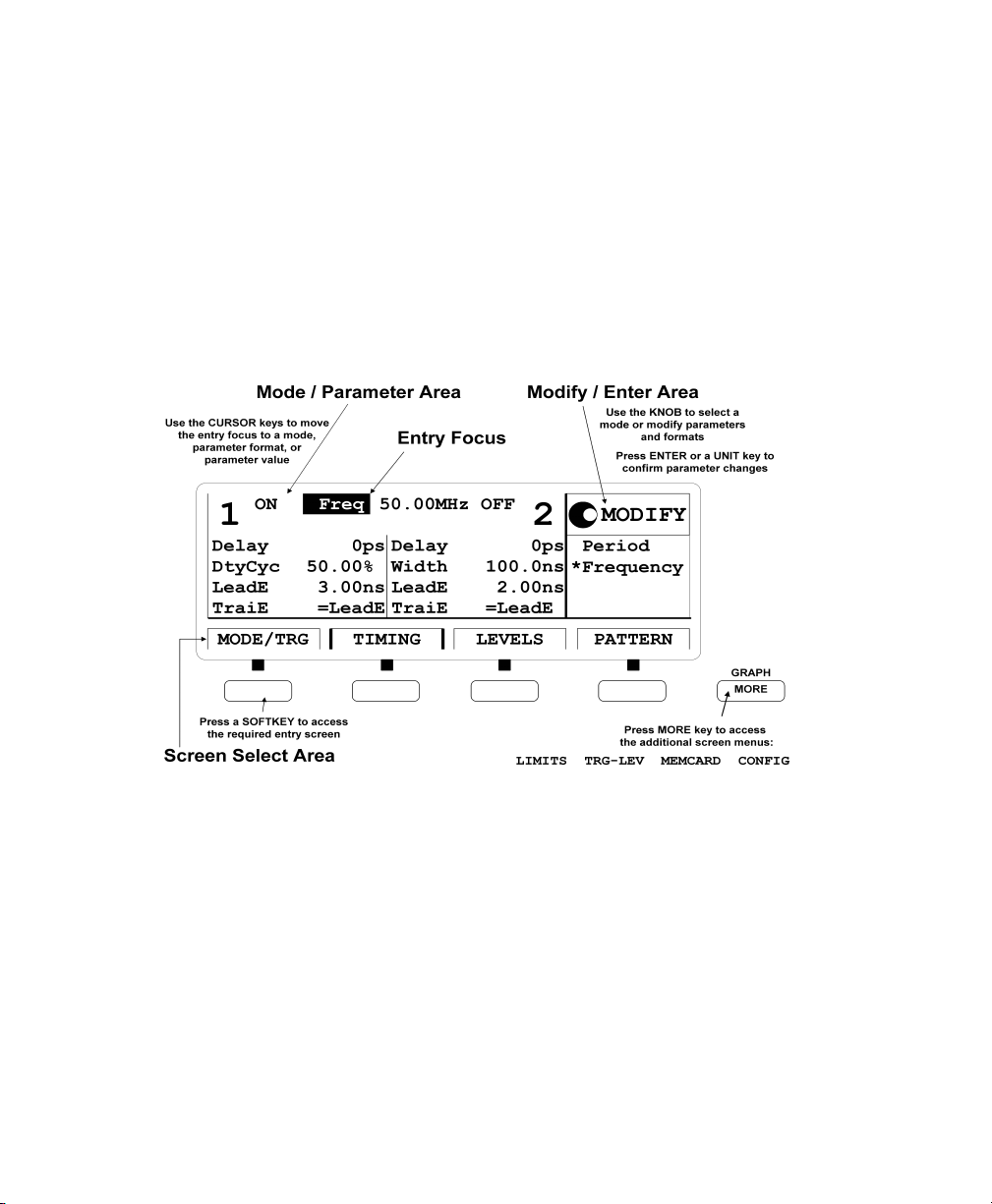
Adjusting Parameters
Adjusting parameters within a screen, requires two steps:
selecting the parameter
adjusting its value
Some parameters allow different formats of their values. For example,
the pulse width can be displayed and entered as an absolute value, as
duty cycle (percentage of the period), or as the delay of the trailing edge.
The following sections show the standard procedure for adjusting
parameters, and list some features useful for the advanced user.
Standard Procedure
To experience the standard procedure for adjusting parameters, consider
the following example where the duty cycle is set to 50%.
Press the TIMING softkey to access the Timing screen.
1
Use the cursor keys to select the W
2
Selection Modify/Enter Area
OFF Per 1.000 µs OFF
1
OFF OFF
Delay
Width
0ps
100.0ns
Delay 0ps
Width
parameter.
IDTH
2
100.0ns
MODIFY
*Width
DutyCycle
TrailDel
TIMING PATTERNLEVELSMODE/TRG
The available formats for the pulse width parameter are displayed in
the Modify/Enter area.
24

Introducing the 81110A/81104A Pulse and Pattern Generators
OOOOppppeeeerrrraaaattttiiiing
ng tttthe
he 81110
ng ng
he he
81110AAAA////81104
8111081110
81104AAAA
8110481104
When changing the
parameter format,
the instrument
automatically
recalculates the
value.
3 Turn the knob to select D
The selected setting is indicated by an *.
4 Move the cursor to the right to select the duty cycle value.
5 Use the data entry keys or the knob to enter the required value: 50.
6 Press the ENTER key to confirm your selection.
UTYCYCLE
.
ON Per 1.000µs OFF
1
OFF OFF
Delay
DtyCyc
0ps
50.0%
Delay 0ps
Width 100.0ns
2
MODIFY
50.0
%
TIMING PATTERNLEVELSMODE/TRG
If you need to specify a unit for a parameter, simply press the appropriate
unit key (
With this small example, you have learned the basic steps required for
adjusting parameters. For a complete reference of parameters and
formats available in the individual screens, refer to Chapter 3 Using the
81110A/81104A on page 59.
NANO, MICRO/MEGA, MILLI/KILO) instead of the
ENTER
key.
25

Introducing the 81110A/81104A Pulse and Pattern Generators
OOOOppppeeeerrrraaaattttiiiinnnng
g tttthhhhe
e 81110
g g
e e
81110AAAA////81104
8111081110
81104AAAA
8110481104
Advanced Procedures
The following features can be used to make operation more comfortable.
Selecting parameters
SHIFT
Most keys of the front panel have an additional function. The SHIFT
key provides fast access to the additional functions of the data entry
keys and the special function keys.
For example, it is possible to quickly access the pulse width
parameter by pressing SHIFT + 6 (WIDTH). The entry focus will be
positioned on the corresponding editing field.
Changing the step size
SHIFT
SHIFT
NNNNOOOOTE
TE Proper operation of the instrument outside of the specified ranges is not
TETE
When modifying a value in the Modify/Enter area, pressing the SHIFT
key followed by cursor left/right moves the cursor to a different digit
in the displayed number.
Thus, you can change the step size for parameter change before you
vary the value either with the up/down cursor keys or the knob.
Overprogramming
Pressing the SHIFT key while turning the knob, it is possible to exceed
specified parameter ranges to utilize the instrument to its limits.
guaranteed. It is recommended to have the output switched on when
overprogramming to have the internal error check system activated. This
error check system warns you about impossible settings.
26

Introducing the 81110A/81104A Pulse and Pattern Generators
OOOOppppeeeerrrraaaattttiiiing
ng tttthe
he 81110
ng ng
he he
81110AAAA////81104
8111081110
81104AAAA
8110481104
Switching the Outputs On and Off
When you switch the instrument on, the outputs and inverted outputs are
switched off to protect the device under test. The LED indicator next to
the connector indicates the output state.
ON/OFF1
0
For example, to switch output 1 on or off
either press SHIFT + 0 (ON/OFF1),
or move the cursor to the ON/OFF parameter in the Timing or Levels
screen and select the appropriate value by turning the knob.
To switch on or off output 2 and/or the inverted outputs, proceed in the
same way. You can use the following short cuts:
Short Cut Output
SHIFT + 0 (ON/OFF1) Normal Out 1
SHIFT + . (decimal point) (ON/OFF1
SHIFT + +/- (ON/OFF2) Normal Out 2
SHIFT + ENTER (ON/OFF2
) Inverted Out 2
) Inverted Out 1
27

Introducing the 81110A/81104A Pulse and Pattern Generators
OOOOppppeeeerrrraaaattttiiiinnnng
g tttthhhhe
e 81110
g g
e e
81110AAAA////81104
8111081110
81104AAAA
8110481104
Using the Special Function Keys
The instrument provides the following special function keys:
The MAN key can be used to run and to stop the instrument, and, in
MAN
RECALL
STORE
SHIFT
LOCAL
HELP
triggered or gated mode, to manually arm and/or trigger the
instrument if there is no other source available (see The
Mode/Trigger Screen on page 60).
The STORE key can be used to store/recall to/from 1 to 9 individual
settings in the instrument memory.
In the internal memory location 0 there is a default setting stored.
Pressing SHIFT + STORE (RECALL) and selecting 0 resets the instrument to
the default setting.
The SHIFT key provides fast access to additional functions.
When the front panel controls are locked in remote control, pressing
the SHIFT key unlocks the front panel controls.
The HELP key provides access to the instruments on-line help or in
warning or error state, access to Warning/Error Report screen.
Pressing SHIFT + HELP (AUTOSET) sets the instrument to a valid
setting based on the current period setting.
28

Introducing the 81110A/81104A Pulse and Pattern Generators
HHHHeeeellllp
p iiiis
s AAAAvvvvaaaaiiiillllab
p p
s s
Help is Available
Whenever you are in doubt or the instrument signals warnings or errors,
press the HELP key.
HHHHeeeellllpppp If there are no warnings or errors pending, pressing the HELP key
displays information on the currently selected parameter, the parameter
help. More information is available within the help system:
Parameter Help
The help information gives a short description of the parameter or
setting options and the corresponding SCPI command(s) syntax for
programming the parameter or setting.
If there is more than one screen available (indicated by small arrows),
use the knob or the cursor keys to scroll through the help
information.
To access parameter help from other screens of the help system,
press the ON FIELD softkey.
ablllleeee
abab
Concept Help
Pressing the CONCEPT softkey within the help system displays a short
description of the instrument.
Serial Numbers and Software Revision
Pressing the SERIAL # softkey within the help system displays
information on serial numbers and software revision codes of the
instrument.
WWWWaaaarrrrnnnniiiing
ngs
s aaaannnnd
d
ngng
s s
EEEErr
rroooorrrrssss
rrrr
EEEExxxxiiiit
t HHHHeeeellllpppp To exit from the help system, press the HELP key again, or press the EXIT
t t
If there are warnings or errors pending (indicated by a flushing W or E),
d d
pressing the HELP key displays a list of the current messages. Using the
ERROR QU and WARNING softkeys, you can toggle between both lists. For
more information on warnings and errors, see Warnings and Errors on
page 107.
HELP softkey.
29

Introducing the 81110A/81104A Pulse and Pattern Generators
TTTThe
he RRRReeeeaaaar
r PPPPan
he he
aneeeellll
r r
anan
The Rear Panel
The rear panel always provides two connectors:
The external input (EXT INPUT) can be used to connect an external
arming source (started or gated modes).
The input connector for external clock or PLL reference
(CLOCK/REF INPUT) can be used if a higher frequency accuracy is
required.
The GP-IB connector providing the interface for remote control.
The following figure shows the rear panel view with the option UN2.
CLK/REF InputExternal Input GP-IB Connector
Inputs and Outputs
With option UN2 the major inputs and outputs of the instrument (as
described in The Front Panel on page 18) are available at the rear
panel:
external input (EXT INPUT)
clock/reference input (CLK/REF INPUT)
trigger signal (TRIGGER OUT)
signal output (OUTPUT)
30
Fuse Holder
AC Line Socket
Serial Number

2
2Getting Started
The intention of this chapter is to give the necessary steps to set up
generic signals for first-time users of the 81110A/81104A.
This chapter provides examples for the following types of signals:
Setting Up a Clock Signal on page 32
Setting Up a Pulse Signal on page 37
Setting Up a Serial Data Stream Signal on page 41
Setting Up an Edge-Displacement Signal on page 45
Setting Up a Dual Clock Signals on page 50
Setting Up a Burst Signal on page 55
At the end of each example, the required set of device commands is listed
to provide programming examples. For further information on the
commands and a complete command reference please refer to the
Reference Guide, p/n 81110-91021.
The examples are intended to be performed one after the other.
Therefore, the first example provides the most detailed instructions,
while the other examples are described on a higher level.
31

Getting Started
SSSSeeeett
ttiiiinnnng
g UUUUp a
p a CCCClllloc
ock
k SSSSiiiiggggna
tttt
g g
p a p a
ococ
nallll
k k
nana
Setting Up a Clock Signal
TTTTaaaask
sk Set up a continuous clock signal with 50 MHz frequency with PLL
sksk
accuracy, a duty cycle of 50 %, 3 ns transition times, a high level of 2.5 V
and a low level of 0 V.
IIIInnnnssssttttrrrruc
ucttttiiiion
ucuc
onssss To set the
onon
1
Reset all parameters and modes by pressing SHIFT + STORE (RECALL) + 0.
2
Press the MODE/TRG softkey to enter the Mode/Trigger screen.
Trigger mode CONTINUOUS and operating mode PULSES are
selected by default.
3
Move the entry focus down to select S
P
ULSE-PERIOD: INTERNAL
32
operating mode and trigger mode
INGLE-PULSES AT OUT
PLL.
as required:
1 and then

Getting Started
SSSSeeeettttttttiiiinnnng
g UUUUp
p a
a CCCClllloooocccck
g g
p p
k SSSSiiiign
a a
k k
To set the timing parameters as required:
1 Press the TIMING softkey to enter the Timing menu.
2 Move the entry focus to the output 1 status with the cursor keys.
Select ON in the Modify area to turn on the output 1.
This turns on the output 1 and activates the internal error check to
detect parameter conflicts.
gnaaaallll
gngn
3 Move the entry focus to P
4 Move the entry focus to the F
50 MHz by pressing 5 + 0 +
and select F
ER
entry field and enter a value of
REQ
/ M
MICRO
EGA
REQ
.
.
5 Move the entry focus down to the width of output 1 and select
D
UTYCYC
.
6 Move the entry focus to the right and enter 50% by typing 5 + 0 +
ENTER.
7 Move the entry focus down to enter 3 +
Trailing edge should be the same as leading edge (T
NNNNOOOOTE
TE With Agilent 81110A with Agilent 81112A 3.8V/330 MHz output channels
TETE
for the leading edge.
NANO
RAIL
E = L
installed the transition times can be either 800 ps or 1.6 ns, trailing edge
is equal to leading edge. The minimum transition times for the
Agilent 81104A are 3 ns.
EAD
E).
33

Getting Started
SSSSeeeett
ttiiiinnnng
g UUUUp a
p a CCCClllloc
tttt
g g
p a p a
ock
k SSSSiiiiggggna
nallll
ococ
k k
nana
To set the level parameters as required:
1 Press the LEVELS softkey to enter the Levels menu.
2 Move the entry focus to O
area select H
IGH-LOW
FFSET
and A
MPLITUDE
and in the MODIFY
.
3 Move the entry focus to the high level entry field and press 2 + . + 5 +
ENTER for the high level.
4 Move down the entry focus to the low level entry field and press 0 +
ENTER.
For the Agilent 81104A or 81110A with an 81105 module installed, the
screen looks as follows.
For the Agilent 81110A with an 81112 module installed, the screen
looks as follows.
34

Getting Started
SSSSeeeettttttttiiiinnnng
g UUUUp
p a
a CCCClllloooocccck
k SSSSiiiign
g g
p p
a a
The following figure shows the signal as displayed on the Agilent 54810A
Infinium Oscilloscope. Use the generators TRIGGER OUT to trigger the
scope.
gnaaaallll
k k
gngn
35

Getting Started
SSSSeeeett
ttiiiinnnng
g UUUUp a
p a CCCClllloc
tttt
g g
p a p a
ock
k SSSSiiiiggggna
ococ
k k
nallll
nana
PPPPrrrrooooggggrrrraaaammmmmmmmiiiing
ng
ng ng
EEEExxxxaaaammmmpppplllleeee
If you want to include this clock signal in your GP-IB program, use the
following command lines. The comment lines starting with a # are not
required.
# Reset the instrument to start from a defined, default status.
*RST
# Switch off the automatic display update to increase programming
# speed.
:DISPlay OFF
# Internal PLL has to be set as period source.
:ARM:SOURce INT2
# Set the frequency to 50 MHz, the duty cycle to 50% and the leading
# and trailing edge to 3 ns. Settings are to program for output 1.
:FREQuency 50MHZ
:PULSe:DCYCle1 50
:PULSe:TRANsition1 3NS
# For example, the same settings for the optional second channel will
# look like as follows:
:PULSe:DCYCle2 50
:PULSe:TRANsition2 3NS
# Set the high level to 2.5 Volts, the low level to 0.0 Volts.
:VOLTage1:HIGH 2.5V
:VOLTage1:LOW 0V
# Enable the output 1 and the complement output 1 (Agilent 81110A
# with Agilent 81112A 3.8V/330 MHz output channel installed, only).
:OUTPut1 ON
:OUTPut1:COMPlement ON
36

Getting Started
SSSSeeeettttttttiiiinnnng
g UUUUp
p a
a PPPPuuuullllsssse
g g
p p
e SSSSiiiign
a a
e e
Setting Up a Pulse Signal
TTTTaaaask
sk Set up a continuous pulse signal with 20 ns period, a pulse width of 10 ns,
sksk
a leading edge of 3 ns, a trailing edge of 5 ns, an amplitude of 3.3 V and an
offset of 1.65 V (high level 3.3 V, low level 0.0 V).
gnaaaallll
gngn
IIIInnnnssssttttrrrruc
ucttttiiiion
ucuc
onssss To set the
onon
1
Reset all parameters and modes by pressing SHIFT + STORE (RECALL) + 0.
For reference the current MODE/TRG screen is displayed. There is
nothing to change.
To set the
1
Press the TIMING softkey to enter the Timing menu.
operating mode and trigger mode
timing parameters
as required:
as required:
37

Getting Started
SSSSeeeett
ttiiiinnnng
g UUUUp a
p a PPPPuuuullllsssse
tttt
g g
p a p a
e SSSSiiiiggggna
nallll
e e
nana
2 Switch ON the output channel 1.
3 Enter a period of 20
4 Enter 3
for leading edge. Select A
NS
enter a value of 5
NNNNOOOOTE
TE With Agilent 81110A with Agilent 81112A 3.8V/330 MHz output channels
TETE
. Enter a pulse width of 10 NS.
NS
BSOLUTE
.
NS
for trailing edge and
installed the transition times can be either 800 ps or 1.6 ns, trailing edge
is equal to leading edge. The minimum transition times for the
Agilent 81104A are 3 ns.
To set the level parameters as required:
1 Press the LEVELS softkey.
2 Enter an offset of 1.65 V and an amplitude of 3.30 V.
For the Agilent 81104A or 81110A with an 81105 module installed, the
screen looks as follows.
For the Agilent 81110A with an 81112 module installed, the screen
looks as follows.
38

Getting Started
SSSSeeeettttttttiiiinnnng
g UUUUp
p a
a PPPPuuuullllsssse
e SSSSiiiign
g g
p p
a a
The following figure shows the signal as displayed on the Agilent 54810A
Infinium Oscilloscope. Use the generators TRIGGER OUT to trigger the
scope.
gnaaaallll
e e
gngn
39

Getting Started
SSSSeeeett
ttiiiinnnng
g UUUUp a
p a PPPPuuuullllsssse
tttt
g g
p a p a
e SSSSiiiiggggna
nallll
e e
nana
PPPPrrrrooooggggrrrraaaammmmmmmmiiiing
EEEExxxxaaaammmmpppplllleeee
ng
ng ng
If you want to include this burst signal in your GP-IB program use the
following command lines. The comment lines starting with a # are not
required.
# Reset the instrument to start from a defined, default status.
*RST
# Switch off the automatic display update to increase programming
# speed.
:DISPlay OFF
# Pulse stream operating mode is required, but as we start from a
# default status it is not necessary to send a command for setting the
# instrument into pulse stream operating mode.
# Set the period to 20 ns, the pulse width to 10 ns, the leading edge to
# 3 ns and the trailing edge to 5 ns.
:PULSe:PERiod 20NS
:PULSe:WIDTh1 10NS
:PULSe:TRANsition1 3NS
:PULSe:TRANsition1:TRAiling:AUTO OFF
:PULSe:TRANsition1:TRAiling 5NS
NNNNOOOOTE
TE For Agilent 81110A with Agilent 81112A 3.8V/330 MHz output channel
TETE
installed the transitions can be selected either 800 ps or 1.6 ns. Leading
and trailing edge are equal.
# Set the amplitude to 3.3 Volts, the offset to 1.65 Volts.
:VOLTage1 3.3V
:VOLTage1:OFFSet 1.65V
# Enable the output 1 and the complement output 1 (Agilent 81110A
# with Agilent 81112A 3.8V/330 MHz output channel installed, only).
:OUTPut1 ON
:OUTPut1:COMPlement ON
40

Getting Started
SSSSeeeett
ttiiiinnnng
g UUUUp a
tttt
p a SSSSeeeerrrriiiiaaaal
g g
p a p a
l DDDDaaaatttta
l l
a SSSSttttrrrreeeeaaaam
a a
Setting Up a Serial Data Stream Signal
TTTTaaaask
sk Set up a continuous 24-bit long pattern signal with NRZ data output
sksk
format at 80 MBit/s and ECL output level. The pattern is
111001110011001001010010.
IIIInnnnssssttttrrrruc
ucttttiiiion
ucuc
onssss To set the
onon
1
Reset all parameters and modes by pressing SHIFT + STORE (RECALL) + 0.
2
Press the MODE/TRG softkey to enter the Mode/Trigger screen.
3
Select CONTINUOUS PATTERN
4
Highlight RZ-P
operating mode and trigger mode
.
OF
ULSES AT OUT
1 and select NRZ.
as required:
m SSSSiiiign
gnaaaallll
m m
gngn
To set the
1
Press the TIMING softkey to enter the Timing menu.
2
Switch ON the output 1.
3
Enter a frequency of 80 MH
timing parameters
as required:
.
Z
41

Getting Started
SSSSeeeett
ttiiiinnnng
g UUUUp a
p a SSSSeeeerrrriiiiaaaal
tttt
g g
p a p a
NNNNOOOOTE
TE It is recommended to set the width for channel 2 to 6.250 ns to avoid a
TETE
l DDDDaaaatttta
l l
a SSSSttttrrrrea
eam
a a
eaea
m SSSSiiiiggggnnnnaaaallll
m m
parameter conflict when switching on this channel.
The ‘-------’ in the output 1 width entry field relate to the NRZ data
output format selection.
To set the level parameters as required:
1 Press the LEVELS softkey to enter the Level menu.
2 Change Offset and Amplitude mode to ECL levels by selecting
S
ECL in the Modify Area.
ET
NNNNOOOOTE
TE An Agilent 81110A with Agilent 81112A 3.8V/330 MHz output channels
TETE
installed has fixed 50 Ω source impedance and does not offer to adjust
for a load impedance other than 50 Ω.
42

To set up the pattern as required:
1 Press the PATTERN softkey.
SSSSeeeett
ttiiiinnnng
tttt
g UUUUp a
p a SSSSeeeerrrriiiiaaaal
g g
p a p a
Getting Started
l DDDDaaaatttta
a SSSSttttrrrreeeeaaaam
l l
a a
m SSSSiiiign
gnaaaallll
m m
gngn
2 Move the entry focus to L
and enter a value of 24.
AST
3 Move the entry focus to the bit-editing window for CH1 and enter the
pattern 111001110011001001010010 by pressing the 0 or 1 key,
respectively.
When entering the pattern the bit-editing window automatically
moves one location to the right after each key stroke. By turning the
knob counterclockwise you can move the bit-editing window back.
The currently selected memory location is shown by A
NNNNOOOOTE
TE To get a stable display of the pattern stream on an oscilloscope set the
TETE
DDR
.
Strobe (STRB) and trigger the scope.
43

Getting Started
SSSSeeeett
ttiiiinnnng
g UUUUp a
p a SSSSeeeerrrriiiiaaaal
tttt
g g
p a p a
l DDDDaaaatttta
l l
a SSSSttttrrrrea
eam
a a
eaea
m SSSSiiiiggggnnnnaaaallll
m m
PPPPrrrrooooggggrrrraaaammmmmmmmiiiing
ng
ng ng
EEEExxxxaaaammmmpppplllleeee
If you want to include this burst signal in your GP-IB program use the
following command lines. The comment lines starting with a # are not
required.
# Reset the instrument to start from a defined, default status.
*RST
# Switch off the automatic display update to increase programming
# speed.
:DISPlay OFF
# Set the instrument to pattern mode and select NRZ data output format
# for output 1.
:DIGital:PATTern ON
:DIGital:SIGNal1:FORMat NRZ
# For example the command to set NRZ data format for the optional
# second channel is:
# :DIGital:SIGNal2:FORMat NRZ
# Define a pattern length of 24 bit and program the pattern:
# ‘111001110011001001010010’.
:TRIGger:COUNt 24
:DIGital:PATTern:DATA1 #224111001110011001001010010
# Set the frequency to 80 MHz, and output 2 width to 6.25 ns to avoid a
# parameter conflict.
:FREQuency 80MHZ
:PULSe:WIDTh2 6.25NS
# Set the output voltage to fixed ECL levels.
:VOLTage1:HIGH -0.85V
:VOLTage1:LOW -1.8V
# Enable the output 1 and the complement output 1 (Agilent 81110A
# with Agilent 81112A 3.8V/330 MHz output channel installed, only).
:OUTPut1 ON
:OUTPut1:COMPlement ON
44

Getting Started
SSSSeeeettttttttiiiing
ng UUUUp a
p an E
n Edg
ng ng
p ap a
n En E
dgeeee----DDDDiiiissssppppllllaaaace
dgdg
cemmmmeeeennnnt
cece
Setting Up an Edge-Displacement Signal
TTTTaaaask
sk Set up a continuous signal with one distorted pulse. The two channels
sksk
are added with NRZ (Non Return to Zero) at both outputs. The high level
is 1 V, low level is 0 V. The delay of output 2 is 10 ns and the bit frequency
is 30 MHz.
NNNNOOOOTE
TE For this example, both outputs and the channel addition feature are
TETE
required. Therefore, this type of signal can only be performed with
Agilent 81104A and Agilent 81110A with Agilent 81111A 10V/165 MHz
outputs.
t SSSSiiiign
gnaaaallll
t t
gngn
45

Getting Started
SSSSeeeett
ttiiiinnnng
g UUUUp an E
p an Eddddge
tttt
g g
p an Ep an E
IIIInnnnssssttttrrrruc
ucttttiiiion
onssss To set the operating mode and trigger mode as required:
ucuc
onon
ge----DDDDiiiissssppppllllaaaacccceeeemmmmeeeennnnt
gege
t SSSSiiiiggggna
nallll
t t
nana
1 Reset all parameters and modes by pressing SHIFT + STORE (RECALL) + 0.
2 Press the MODE/TRG softkey to enter the Mode/Trigger screen.
3 Select CONTINUOUS PATTERN
4 Select NRZ-P
at Out 1 and NRZ-P
ULSES
OF
.
at Out 2 using the
ULSES
MODIFY knob.
To set up the pattern as required:
1 Press the PATTERN softkey.
2 Set up the bit pattern as follows. Enter 8 for L
AST
.
3 Move to the bit-editing window for CH1 and enter pattern 10100010
for channel 1.
4 Move down to CH2 and select first address by turning the knob
counterclockwise.
5 Enter pattern 00001000 for channel 2.
46

SSSSeeeettttttttiiiing
To set the level parameters as required:
1 Press the LEVELS softkey.
2 Switch ON both channels.
ng UUUUp a
p an E
ng ng
p ap a
n Edg
dgeeee----DDDDiiiissssppppllllaaaace
n En E
dgdg
Getting Started
cemmmmeeeennnnt
t SSSSiiiign
cece
gnaaaallll
t t
gngn
3 Change S
EPARATE OUTPUTS
4 Set high level to 1.00 V and low level to 0.0
to A
DDED AT OUTPUT
1.
V for both outputs.
M
To set the timing parameters as required:
1 Press the TIMING softkey.
2 Enter a frequency of 30 MH
and a delay of 10 NS for output 2.
Z
3 Vary output 2 delay to displace the pulse as required.
Output 2 has additional 2.5 ns delay in channel addition mode. Also,
the typical transition times are 5 ns.
4 Enter transitions of 5 ns for output 1 to achieve same transition time
shape in the added signal.
47

Getting Started
SSSSeeeett
ttiiiinnnng
g UUUUp an E
p an Eddddge
tttt
g g
p an Ep an E
NNNNOOOOTE
TE The ‘-------’ in the width entry fields relate to the NRZ data output
TETE
ge----DDDDiiiissssppppllllaaaacccceeeemmmmeeeennnnt
gege
format selection.
The following figure shows the signal as displayed on the Agilent 54810A
Infinium Oscilloscope. Use the generators STROBE OUT to trigger the
scope.
t SSSSiiiiggggna
nallll
t t
nana
48

SSSSeeeettttttttiiiing
ng UUUUp a
ng ng
p an E
n Edg
p ap a
n En E
Getting Started
dgeeee----DDDDiiiissssppppllllaaaace
dgdg
cemmmmeeeennnnt
cece
t SSSSiiiign
gnaaaallll
t t
gngn
PPPPrrrrooooggggrrrraaaammmmmmmmiiiing
EEEExxxxaaaammmmpppplllleeee
ng
ng ng
If you want to include this burst signal in your GP-IB program use the
following command lines. The comment lines starting with a # are not
required.
NNNNOOOOTE
TE Two outputs and the channel addition feature are required for this
TETE
example. Therefore, this example can be performed by Agilent 81104A
and Agilent 81110A with Agilent 81111A 10V/165 MHz outputs.
# Reset the instrument to start from a defined, default status.
*RST
# Switch off the automatic display update to increase programming
# speed.
:DISPlay OFF
# Set the instrument to pattern mode and select NRZ data output format
# for output 1 and output 2.
:DIGital:PATTern ON
:DIGital:SIGNal1:FORMat NRZ
:DIGital:SIGNal2:FORMat NRZ
# Define a pattern length of 8 bit and program for channel 1 the pattern
# 10100010, for the channel 2 the pattern 00001000, see manual step 3.
:TRIGger:COUNt 8
:DIGital:PATTern:DATA1 #1810100010
:DIGital:PATTern:DATA2 #1800001000
# Set the frequency to 30 MHz, and a delay of 10 ns for output 2, the
# transition times for output 1 to 5ns to have same transition time
# shape as the added second channel, see comment in step 5.
:FREQuency 30MHZ
:PULSe:TRANsition1 5NS
:PULSe:DELay2 10NS
# Set the output voltage to high level 1.0 Volts and low level to 0.0 Volts
# for both channels. Then select channel addition mode, see manual
# step 4.
:VOLTage1:HIGH 1V
:VOLTage1:LOW 0V
:VOLTage2:HIGH 1V
:VOLTage2:LOW 0V
:CHANnel:MATH PLUS
# Enable the output 1 and the output 2.
:OUTPut1 ON
:OUTPut2 ON
49

Getting Started
SSSSeeeett
ttiiiinnnng
g UUUUp a
p a DDDDua
ual
l CCCClllloc
ock
tttt
g g
p a p a
uaua
l l
k SSSSiiiiggggnnnnaaaallllssss
ococ
k k
Setting Up a Dual Clock Signals
TTTTaaaask
sk Set up a Dual Clock Signal in pattern mode with NRZ (Non Return to
sksk
Zero) pulses, a period of 12.5 ns and a high level of 2.50 V and a low level
of 0 V. Output 1 generates a clock signal that is half of the system clock.
Output 2 divides the system clock by 8.
NNNNOOOOTE
TE For this example two outputs are required.
TETE
NNNNOOOOTE
TE With an additional dual channel instrument, multiples of these dual clock
TETE
signals can be set up following a similar procedure as follows. For
example, with 8 dual channel units up to 16 different clocks can be
generated.
50

IIIInnnnssssttttrrrruc
ucttttiiiion
ucuc
SSSSeeeettttttttiiiinnnng
g UUUUp a
p a DDDDuuuuaaaal
g g
p a p a
onssss To set the operating mode and trigger mode as required:
onon
1 Reset all parameters and modes by pressing SHIFT + STORE + 0.
2 Press the MODE/TRG softkey to enter the Mode/Trigger screen.
Getting Started
l CCCClllloooocccck
k SSSSiiiign
l l
gnaaaallllssss
k k
gngn
3 Select P
ATTERN OF
with NRZ-PULSES AT OUT 1 & OUT 2.
To set up the pattern as required:
1 Press the PATTERN softkey.
2 Enter 8 for L
AST
.
3 Move to CH1, select Clock÷N, and press the ENTER key twice to get
a pattern for clock division by 2.
4 Move to CH2, select Clock÷N, and press ENTER key. Press 8 and
ENTER, to get a pattern for clock division by 8.
51

Getting Started
SSSSeeeett
ttiiiinnnng
g UUUUp a
p a DDDDua
tttt
g g
p a p a
ual
l CCCClllloc
ock
uaua
k SSSSiiiiggggnnnnaaaallllssss
l l
ococ
k k
To set the timing parameters as required:
1 Press the TIMING softkey.
2 Switch ON both outputs.
To set the levels parameters as required:
1 Press the LEVELS softkey.
2 Set high levels of 2.50 V and low levels of 0.0
Set the period to 12.5 NS.
V for both outputs.
M
NNNNOOOOTE
TE The TIMING and LEVELS screens for Agilent 81110A with
TETE
Agilent 81112A 3.8V/330 MHz outputs look different to the screens shown
here. This instrument has no channel addition, fixed source impedance
of 50 Ω, assumes 50 Ω load impedance and has differential outputs.
52

Getting Started
SSSSeeeettttttttiiiinnnng
g UUUUp a
p a DDDDuuuuaaaal
g g
p a p a
The following figure shows the signals as displayed on the
Agilent 54810A Infinium Oscilloscope. Use the generators STROBE OUT
to trigger the scope.
l CCCClllloooocccck
l l
k SSSSiiiign
gnaaaallllssss
k k
gngn
53

Getting Started
SSSSeeeett
ttiiiinnnng
g UUUUp a
p a DDDDua
tttt
g g
p a p a
ual
uaua
l CCCClllloc
ock
l l
ococ
k SSSSiiiiggggnnnnaaaallllssss
k k
PPPPrrrrooooggggrrrraaaammmmmmmmiiiing
ng
ng ng
EEEExxxxaaaammmmpppplllleeee
NNNNOOOOTE
TE A second channel is required.
TETE
If you want to include this burst signal in your GP-IB program use the
following command lines. The comment lines starting with a # are not
required.
# Reset the instrument to start from a defined, default status.
*RST
# Switch off the automatic display update to increase programming
# speed.
:DISPlay OFF
# Set the instrument to pattern mode and select NRZ data output format
# for output 1 and output2.
:DIGital:PATTern ON
:DIGital:SIGNa1l:FORMat NRZ
:DIGital:SIGNal2:FORMat NRZ
# Define a pattern length of 8 bit and program for channel 1 a pattern
# with clock division by 2, for channel 2 a pattern with clock division
# by 8.
:TRIGger:COUNt 8
:DIGital:PATTern:PRESet1 2,8
:DIGital:PATTern:PRESet2 8,8
# Set the period to 12.5 ns.
:PULSe:PERiod 12.5NS
# Set the output voltage to high level 2.5 Volts and low level to 0.0 Volts
# for both channels.
:VOLTage1:HIGH 2.5V
:VOLTage1:LOW 0V
:VOLTage2:HIGH 2.5V
:VOLTage2:LOW 0V
# Enable the output 1 and the output 2.
:OUTPut1 ON
:OUTPut2 ON
# To enable the complement output 1 and the complement output 2
# (only Agilent 81110A with Agilent 81112A 10V/330 MHz outputs installed)
# the following commands have to be included:
:OUTPut1:COMPlement ON
:OUTPut2:COMPlement ON
54

Getting Started
SSSSeeeett
ttiiiinnnng
g UUUUp a
p a BBBBuuuurrrrsssst
tttt
g g
p a p a
Setting Up a Burst Signal
TTTTaaaask
sk Set up a burst signal with a burst repetition of 5 µs. One signal should
sksk
have two pulses at the period 500 ns. The levels are 2Vpp amplitude and
offset of 0V.
NNNNOOOOTE
TE For this example two outputs are required.
TETE
t SSSSiiiign
gnaaaallll
t t
gngn
IIIInnnnssssttttrrrruc
ucttttiiiion
ucuc
onssss To set the
onon
1
Reset all parameters and modes by pressing SHIFT + STORE + 0.
2
Press the MODE/TRG softkey to enter the Mode/Trigger screen.
The internal PLL is used to trigger the startable internal oscillator.
The PLL defines the burst repetition, the oscillator generates the
pulse period.
3
Move to CONTINUOUS and select TRIGGERED.
4
Move to PULSES and select BURST
5
Move down and set 5 - S
O
2.
UT
operating mode and trigger mode
.
OF
INGLE-PULSES AT OUT
as required:
1 and D
OUBLE-PULSES AT
55

Getting Started
SSSSeeeett
ttiiiinnnng
g UUUUp a
p a BBBBuuuurrrrsssst
tttt
g g
p a p a
t SSSSiiiiggggnnnnaaaallll
t t
6 Move down and select TRGD
: PLL → PER and set the burst
BY
repetition to 5.000 µs.
To set the timing parameters as required:
1 Press the TIMING softkey.
2 Switch the output 1 and the output 2 ON.
3 Enter a pulse period of 500 ns. F
4 For output 1 enter a width of 100
the trailing edge to T
RAIL
E = L
, a leading edge of 3 ns and set
NS
E.
EAD
5 For output 2 enter a double pulse delay of 250
leading edge of 3
and set trailing edge to T
NS
, a width of 100NS, a
NS
RAIL
E=L
EAD
E.
56

To set the level parameters as required:
1 Press the LEVELS softkey.
SSSSeeeett
ttiiiinnnng
tttt
g UUUUp a
g g
Getting Started
p a BBBBuuuurrrrsssst
p a p a
t SSSSiiiign
gnaaaallll
t t
gngn
2 Select S
EPARATE OUTPUTS
3 For Channel 1 choose an offset of 0.0
.
V and an amplitude of 2.00 V.
M
4 For Channel 2 choose an offset of 0.0 mV and an amplitude of 2.00 V.
The following figure shows the signals as displayed on the
Agilent 54810A Infinium Oscilloscope. Use the generators STROBE OUT
to trigger the scope.
57

Getting Started
SSSSeeeett
ttiiiinnnng
g UUUUp a
p a BBBBuuuurrrrsssst
tttt
g g
p a p a
t SSSSiiiiggggnnnnaaaallll
t t
PPPPrrrrooooggggrrrraaaammmmmmmmiiiing
EEEExxxxaaaammmmpppplllleeee
ng
ng ng
If you want to include this burst signal in your GP-IB program use the
following command lines. The comment lines starting with a # are not
required.
NNNNOOOOTE
TE A second channel is required.
TETE
# Reset the instrument to start from a defined, default status.
*RST
# Switch off the automatic display update to increase programming
# speed.
:DISPlay OFF
# Set the instrument to burst mode by selecting a burst count of 5.
# Choose double pulses for output 2. Select triggered mode by selecting
# PLL as the trigger source and set the burst repetition to 5 ms.
:TRIGger:COUNt 5 # Set Burst mode with burst count of 5
:ARM:SOURce INT2 # Set Triggered mode with PLL as trigger source
:ARM:PERiod 5US # Set burst repetition of 5 ms
:PULSe:DOUBle2 ON # second channel generates double
# pulses per period
# Set the period to 500 ns, for output 1 enter a width of 100 ns. For
# output 2 set the double pulse to 250 ns and the width to 100 ns. All
# edges set to 3 ns.
:PULSe:PERiod 500NS
:PULSe:WIDTh1 100NS
:PULSe:TRANsition1 3NS
:PULSe:WIDTh2 100NS
:PULSe:DOUBle2 ON
:PULSe:DOUBle2:DELay 250NS
:PULSe:TRANsition2 3NS
# Set the output amplitude to 2 Volts and the offset to 0.0 Volts for both
# channels.
:VOLTage 2V
:VOLTage2 2V
# Enable the output 1 and the output 2.
:OUTPut ON
:OUTPut2 ON
# To enable the complement output 1 and the complement output 2
# (only Agilent 81110A with Agilent 81112A 3.8V/330MHz Outputs installed)
# the following commands have to be included:
:OUTPut:COMPlement ON
:OUTPut2:COMPlement ON
58

3
NNNNOOOOTE
TE For general information on using the 81110A/81104A and information on
TETE
3Using the 81110A/81104A
This chapter provides complete reference information for using the
81110A/81104A by means of the user interface screens.
Each screen is described in detail. To access the individual screens, use
the softkeys below the screen. There are two softkey layouts:
the default layout
TIMING PATTERNLEVELSMODE/TRG
the alternative layout displayed after pressing the MORE key
TRG-LEV CONFIGMEMCARDLIMITS
At the end of this chapter, Warnings and Errors on page 107 provides
details on the instruments warning and error messaging system.
the instruments hardkeys, please refer to Chapter 1 Introducing the
81110A/81104A Pulse and Pattern Generators on page 15.
NNNNOOOOTE
TE For information on using the 81110A/81104A via remote control, please
TETE
refer to the Reference Guide, part number 81110-91021.
59

Using the 81110A/81104A
TTTThe
he MMMMoooode
de////TTTTrrrriiiigg
ggeeeer
he he
dede
gggg
r SSSSccccrrrree
r r
The Mode/Trigger Screen
This section describes the Mode/Trigger screen, starting with an
overview of the available parameter combinations, followed by detailed
descriptions of each combination.
Overview
To access the Mode/Trigger screen, press the MODE/TRG softkey.
The following figure shows a typical Mode/Trigger screen, where the
individual parameters are indicated. The parameter combinations are
listed in the table on the next page.
The following sections explain these combinations in more detail.
eennnn
eeee
60
➀
⑥
④
②
⑤
③

➀
Trigger
Mode
②
Pulse
Mode
③
Pulse
Typ e
Using the 81110A/81104A
Th
The
e MMMMod
ThTh
e e
odeeee////TTTTrrrriiiiggggggggeeeer
odod
r SSSSccccrrrreeeeeeeennnn
r r
In this screen you can set up the overall operating modes of the
instrument.
CONTINUOUS TRIGGERED GATED EXT
PULSES BURST PATTERN PULSES BURST PATTERN PULSES BURST PATTERN
Single/Double RZ/NRZ Single/Double RZ/NRZ Single/Double RZ/NRZ
WIDTH
④
Length
int Osc
⑤
Period
Source
⑥
Arming
Source
TRIGGER OUT
STROBE
OUT
a
int PLL
CLK-IN
Not
Used
PLL cannot be used as Pulse and Arming source at the same time
2-65536 2-16384 2-65536 2-16384 2-65536 2-16384
int Osc
int PLL
CLK-IN
↑
↓
on 1st
on last
Programmable
MAN-Key
EXT
INPUT
Not
Used
MANKey
EXT
INPUT
a
PLL
Marks each pulse period generated
on1st
↑
on last
↓
Pulse Types
The following pulse types can be selected per output:
S
INGLE-PULSES
D
OUBLE-PULSES
Single pulse per period, delay parameter sets delay
to leading edge from start of period.
Double pulse per period, double-delay parameter
sets delay between leading edges of pulses.
Programmable
int Osc
int PLL
CLK-IN
MANKey
EXT
INPUT
Not
Used
on 1st
↑
on last
↓
Programmable
MANKey
EXT
INPUT
Not
Used
61

Using the 81110A/81104A
TTTThe
he MMMMoooode
de////TTTTrrrriiiigg
ggeeeer
he he
dede
gggg
r SSSSccccrrrree
r r
Pattern Formats
In pattern mode the pulse output formats can be selected from:
RZ A single pulse is generated in each pulse period
NRZ A leading edge is generated for a 0→1 data transi-
eennnn
eeee
with data value 1, no pulse is generated for data
value 0.
tion, a trailing edge is generated for a 1→0 data
transition.
62

Using the 81110A/81104A
Th
The
e MMMMod
odeeee////TTTTrrrriiiiggggggggeeeer
ThTh
e e
odod
Continuous Pulses Mode
The following figure shows typical timings for trigger mode
CONTINUOUS and pulse mode PULSES.
r SSSSccccrrrreeeeeeeennnn
r r
CCCChhhhaaaarrrraaaacccctttteeeerrrriiiissssttttiiiiccccssss
Pulse periods are generated continuously
TRIGGER OUT marks each pulse period.
STROBE OUT not used in continuous pulse mode.
63

Using the 81110A/81104A
TTTThe
he MMMMoooode
de////TTTTrrrriiiigg
ggeeeer
he he
dede
gggg
r SSSSccccrrrree
r r
Continuous Burst Mode
The following figure shows typical timings for trigger mode
CONTINUOUS and pulse mode BURST.
eennnn
eeee
CCCChhhhaaaarrrraaaacccctttteeeerrrriiiissssttttiiiiccccssss
A burst of pulse periods is repeated continuously.
You can select the number of pulse periods per burst in the range of
265536.
TRIGGER OUT marks each pulse period.
STROBE OUT rises at the start of the first pulse period in a burst and
falls at the start of the last pulse period.
64

Using the 81110A/81104A
Th
The
e MMMMod
odeeee////TTTTrrrriiiiggggggggeeeer
ThTh
e e
odod
Continuous Pattern Mode
The following figure shows typical timings for trigger mode
CONTINUOUS and pulse mode PATTERN.
r SSSSccccrrrreeeeeeeennnn
r r
CCCChhhhaaaarrrraaaacccctttteeeerrrriiiissssttttiiiiccccssss
A pattern of pulses is repeated continuously.
You can select between RZ and NRZ data pulses for each output.
In the Pattern screen you can set the pattern length in the range 2
16 384 and program the data values for each output.
TRIGGER OUT marks each pulse period.
STROBE OUT is bit-programmable on the Pattern screen (NRZ
format only).
65

Using the 81110A/81104A
TTTThe
he MMMMoooode
de////TTTTrrrriiiigg
ggeeeer
he he
dede
gggg
r SSSSccccrrrree
r r
Triggered Pulses Mode
The following figure shows typical timings for trigger mode TRG'D BY and
pulse mode PULSES.
eennnn
eeee
CCCChhhhaaaarrrraaaacccctttteeeerrrriiiissssttttiiiiccccssss
Single pulse periods are triggered by an active edge at the selected
arming source
MAN key on front panel, triggered by press or release or both.
EXT INPUT (External signal) triggered by rising or falling or both
edges.
TRIGGER OUT marks each pulse period.
66

Using the 81110A/81104A
Th
The
e MMMMod
ThTh
e e
odeeee////TTTTrrrriiiiggggggggeeeer
odod
r SSSSccccrrrreeeeeeeennnn
r r
The following figure shows typical timings when the signal is triggered by
both rising and falling edge of the arming source.
NNNNOOOOTE
TE The PLL cannot be selected as the arming source. Select continuous
TETE
pulses mode with the PLL as P
ERIOD SOURCE
to achieve the same result.
67

Using the 81110A/81104A
TTTThe
he MMMMoooode
de////TTTTrrrriiiigg
ggeeeer
he he
dede
gggg
r SSSSccccrrrree
r r
Triggered Burst Mode
The following figures show typical timings for trigger mode TRIGGERED
and pulse mode BURST.
For the first example, the synchronously triggerable internal oscillator is
used to source the period. The bursts are triggered by the rising edge of
the arming source.
eennnn
eeee
CCCChhhhaaaarrrraaaacccctttteeeerrrriiiissssttttiiiiccccssss
A burst of pulse periods is triggered by an active edge at the selected
arming source
MAN key on front panel, triggered by press or release or both.
EXT INPUT (External signal) triggered by rising or falling or both
edges.
PLL (Internally triggered bursts), select the triggering period.
You can select the number of pulse periods per burst in the range of
265536.
TRIGGER OUT marks each pulse period.
STROBE OUT rises at the start of the first pulse period in a burst and
falls at the start of the last pulse period.
68

Using the 81110A/81104A
Th
The
e MMMMod
odeeee////TTTTrrrriiiiggggggggeeeer
ThTh
e e
odod
For the second example, either the internal PLL or an external CLK-IN
are used to source the periodboth cannot be triggered synchronously.
NNNNOOOOTE
TE You cannot use the PLL as both pulse-period source and as arming
TETE
source at the same time.
r SSSSccccrrrreeeeeeeennnn
r r
69

Using the 81110A/81104A
TTTThe
he MMMMoooode
de////TTTTrrrriiiigg
ggeeeer
he he
dede
gggg
r SSSSccccrrrree
r r
Triggered Pattern Mode
The following figures show typical timings for trigger mode TRIGGERED
and pulse mode PATTERN.
For the first example, the synchronously triggerable internal oscillator is
used to source the period. The patterns are triggered by the rising edge of
the arming source.
eennnn
eeee
CCCChhhhaaaarrrraaaacccctttteeeerrrriiiissssttttiiiiccccssss
A pattern of pulses is triggered by an active edge from the selected
arming source.
MAN K
EXT INPUT (External signal) triggered by rising, falling or both
edges.
PLL (Internally triggered patterns), select the triggering period.
You can select between RZ and NRZ data pulses for each output.
On the Pattern screen you can set the pattern length in the range of 2
16384 and program the data values for each OUTPUT.
TRIGGER OUT marks each pulse period.
STROBE OUT is bit-programmable on the Pattern screen (NRZ
format only).
70
on front panel, triggered by press, release or both.
EY

Using the 81110A/81104A
Th
The
e MMMMod
odeeee////TTTTrrrriiiiggggggggeeeer
ThTh
e e
odod
For the second example, either the internal PLL or an external CLK-IN
are used to source the periodboth cannot be triggered synchronously.
NNNNOOOOTE
TE You cannot use the PLL as both pulse-period source and arming source at
TETE
the same time.
r SSSSccccrrrreeeeeeeennnn
r r
71

Using the 81110A/81104A
TTTThe
he MMMMoooode
de////TTTTrrrriiiigg
ggeeeer
he he
dede
gggg
r SSSSccccrrrree
r r
Gated Pulses Mode
The following figures show typical timings for trigger mode GATED and
pulse mode PULSES.
For the first example, the synchronously triggerable internal oscillator is
used to source the period.
eennnn
eeee
CCCChhhhaaaarrrraaaacccctttteeeerrrriiiissssttttiiiiccccssss
Pulse periods are enabled by (G
selected arming source
MAN K
EXT INPUT (External signal) gated by high, low or both levels.
TRIGGER OUT marks each pulse period.
72
on front panel, gated while pressed or released or both.
EY
ATED BY
) an active level at the

Using the 81110A/81104A
Th
The
e MMMMod
odeeee////TTTTrrrriiiiggggggggeeeer
ThTh
e e
odod
For the second example, either the internal PLL or an external CLK-IN
are used to source the periodboth cannot be triggered synchronously.
r SSSSccccrrrreeeeeeeennnn
r r
73

Using the 81110A/81104A
TTTThe
he MMMMoooode
de////TTTTrrrriiiigg
ggeeeer
he he
dede
gggg
r SSSSccccrrrree
r r
Gated Burst Mode
The following figures show typical timings for trigger mode GATED and
pulse mode BURST.
For the first example, the synchronously triggerable internal oscillator is
used to source the period.
eennnn
eeee
CCCChhhhaaaarrrraaaacccctttteeeerrrriiiissssttttiiiiccccssss
Bursts of pulse periods are enabled by (G
the selected arming source:
MAN key on front panel, gated while pressed or released or both.
EXT INPUT (External signal) gated while high or low or both.
You can select the number of pulse periods per burst in the range 2
65536.
TRIGGER OUT marks each pulse period.
STROBE OUT rises at the start of the first pulse period in a burst and
falls at the start of the last pulse period.
74
ATED BY
) an active level at

Using the 81110A/81104A
Th
The
e MMMMod
odeeee////TTTTrrrriiiiggggggggeeeer
ThTh
e e
odod
For the second example, either the internal PLL or an external CLK-IN
are used to source the periodboth cannot be triggered synchronously.
r SSSSccccrrrreeeeeeeennnn
r r
Gated Pattern Mode
With trigger mode GATED and pulse mode BURST the instrument shows
the following characteristics:
A pattern of pulses is enabled by (G
selected arming source.
MAN key on front panel, gated while pressed, released or both.
EXT INPUT (External signal) gated while high or low or both.
On the Pattern screen you can set the pattern length in the range of 2
16384 and program the data values for each output.
TRIGGER OUT marks each pulse period.
STROBE OUT is bit-programmable on the Pattern screen (NRZ
format only).
ATED BY
) an active level at the
75

Using the 81110A/81104A
TTTThe
he MMMMoooode
de////TTTTrrrriiiigg
ggeeeer
he he
dede
gggg
r SSSSccccrrrree
r r
External Width Mode
In external width mode, the pulse width is determined by an external
signal
eennnn
eeee
The pulse width is determined by an external signal:
MAN key: Pressing the key generates a leading edge, releasing the
key generates a trailing edge.
EXT-IN: A rising-edge at the EXT INPUT generates a leading edge,
a falling edge at the EXT INPUT generates a trailing edge.
The threshold and impedance of the EXT INPUT can be selected on
the Trigger-Level screen.
The period, delay, and width of the output pulse are not
programmable in this mode as they are determined by the external
signal.
76

Using the 81110A/81104A
Th
The
e TTTTiiiimmmmiiiing
e e
ng SSSSccccrrrreeeeeeeennnn
ng ng
ThTh
The Timing Screen
To access the Timing screen press the TIMING softkey.
The Timing screen is only available if you have two channels fitted to
your Agilent 81110A or Agilent 81104A mainframe and you have selected
G
ROUP PARAMS BY
: TIMING/LEVELS on the Configuration screen.
NNNNOOOOTE
TE On screens of the Agilent 81110A with Agilent 81112A 3.8V/330 Mhz
TETE
outputs the second status output is displayed for differential outputs.
The trailing edge is always coupled to the leading edge. The leading edge
can be selected in the range from 0.8 ns and 1.6 ns.
The individual timing parameters are described in more detail in the
following. Parameters can be entered in different formats.
If you prefer to set the timing parameters per output together with the
level parameters of that output, switch the type of parameter grouping.
See Parameter Grouping (Group Params by) on page 104.
77

Using the 81110A/81104A
TTTThe
he TTTTiiiimmmmiiiinnnng
he he
g SSSSccccrrrree
eennnn
g g
eeee
When you press SHIFT + MORE (GRAPH) or the TIMING softkey again, you will
see a graphical representation of the timing parameters of both channels.
The currently selected parameter is displayed in the Modify/Enter area
and is indicated by dashed or bold lines in the graphical display.
Note that in graphics mode you can only adjust the values of each
parameter, not the parameter format. If you want to change the format of
a parameter, for example W
IDTH
to D
UTYCYCLE
, you must be in text mode
to select the parameter name with the cursor.
NNNNOOOOTE
TE With the 81110A/81104A you can sweep your timing values without
TETE
danger of spurious pulses or drop-outs that could cause measurement
errors. This applies to continuous mode with timing values < 100 ms
(frequency: < 10 Hz), and consecutive values between one-half and twice
the previous value.
78

Pulse-Period Parameter
Using the 81110A/81104A
Th
The
e TTTTiiiimmmmiiiing
e e
ng SSSSccccrrrreeeeeeeennnn
ng ng
ThTh
Set the pulse period as either P
NNNNOOOOTE
TE You can select the pulse-period source on the Mode/Trigger screen.
TETE
ERIOD
or F
REQUENCY
.
If you select the CLK IN connector as the pulse-period source, the pulse
period/frequency is determined from the signal applied to CLK IN:
M
EAS ONCE
The external signal is measured once. Press
ENTER to measure again.
M
EAS CONT
The external signal is measured continuously until
the instrument receives a command via GP-IB.
To invoke continuous measurements again you
have to switch the instrument to local operating
mode by pressing S
HIFT
+ L
OCAL
and start
continuous measurement again.
Pulse Delay Parameter
Set the delay of the leading edge within the pulse period. There are three
delay formats available:
(select A
D
ELAY
D
is the absolute delay from the start of a pulse period to the
ELAY
BSOLUTE
)
start of the leading edge of the pulse.
% (select % OF P
D
ELAY
ERIOD
)
The delay from the start of the pulse period to the start of the leading
edge expressed as a percentage of the pulse period.
79

Using the 81110A/81104A
TTTThe
he TTTTiiiimmmmiiiinnnng
he he
g SSSSccccrrrree
eennnn
g g
eeee
P
HASE
(select P
HASE
)
The phase delay in degrees from the start of the pulse period to the
start of the leading edge (360° = 1 pulse period).
Pulse Width Parameter
Set the width of the output pulse. There are three width formats
available:
W
D
IDTH
(select W
IDTH
)
The absolute pulse width measured from the start of the leading edge
to the start of the trailing edge. In this format, the pulse width is
independent of changes in pulse period and delay.
TYCYC
(select D
UTYCYCLE
)
The duty cycle is the pulse width measured from the start of the
leading edge to the start of the trailing edge expressed as a
percentage of the period. In this format, if you adjust the period, the
absolute width is adjusted to maintain the duty cycle.
NNNNOOOOTE
TE You cannot have the width format set to D
TETE
edge format set to percentage of width (L
time.
80
TYCYC
EADED
and the leading/trailing-
%/T
E%) at the same
RAIL

Using the 81110A/81104A
Th
The
e TTTTiiiimmmmiiiing
e e
ng SSSSccccrrrreeeeeeeennnn
ng ng
ThTh
Pulse Trailing-Delay Parameter
The trailing delay is the absolute delay from the start of the pulse period
to the start of the trailing edge. In this format the trailing edge remains
fixed relative to the start of the pulse period if you adjust the pulse-delay
(leading-edge delay) or the pulse period.
Pulse Leading-Edge Parameter
Set the transition time for the leading edge of the pulse, measured from
10% to 90% of the pulse amplitude.
There are two formats available (selectable in text mode):
L
EADED
The absolute transition time measured from 10% to 90% of pulse
amplitude. In this format the leading edge is independent of the pulse
width.
81

Using the 81110A/81104A
TTTThe
he TTTTiiiimmmmiiiinnnng
he he
g SSSSccccrrrree
eennnn
g g
eeee
L
EADED
%
The absolute transition time expressed as a percentage of pulse
width. In this format if you adjust the pulse width, the transition time
is adjusted to maintain the edge-time as a percentage of the width.
NNNNOOOOTE
TE You cannot have the width format set to D
TETE
edge format set to percentage of width (L
EAD
and the leading/trailing
TYCYC
ED%/T
E%) at the same
RAIL
time.
NNNNOOOOTE
TE The leading edge of an Agilent 81110A with Agilent 81112A 3.8 V/330 MHz
TETE
outputs can be selected from 0.8 ns or 1.6 ns.
Pulse Trailing Edge Parameter
Set the trailing-edge transition time of the pulse, measured from 10% to
90% of pulse amplitude.
There are three formats available, selectable in text mode:
=L
T
E
EAD
The trailing-edge transition time is coupled directly to the leading
edge to maintain a symmetrical pulse.
RAILED
The absolute transition time measured from 10% to 90% of pulse
amplitude. In this format the trailing edge is independent of the
leading edge and pulse width.
T
RAIL
E%
The trailing-edge transition time expressed as a percentage of the
pulse width. In this format if you adjust the pulse width, the transition
time is adjusted to maintain the edge-time as a percentage of the
width.
NNNNOOOOTE
TE Note that you cannot have the width format set to D
TETE
TYCYC
leading/trailing edge format set to percentage of width (L
T
E%) at the same time.
RAIL
NNNNOOOOTE
TE The trailing edge of the Agilent 81110A with Agilent 81112A 3.8 V/
TETE
330 MHz outputs is always coupled to the leading edge.
82
and the
EADED
%/

Using the 81110A/81104A
TTTThe
he LLLLeeeevvvveeeelllls
he he
s SSSSccccrrrreeeeeeeennnn
s s
The Levels Screen
To access the Levels screen press the LEVELS softkey.
The Levels screen is only available if you have two channels fitted to
your Agilent 81110A or Agilent 81104A mainframe and you have selected
G
ROUP PARAMS BY
When you press SHIFT + MORE (GRAPH) or the LEVELS softkey, you
will see a graphical representation of the level parameters. The currently
selected parameter is displayed in the Modify/Enter area and is indicated
in the graphical display.
: TIMING/LEVELS on the Configuration screen.
Use the Levels screen to view and control the pulse-level parameter for
both channels on one screen. If you have a single channel instrument
both the timing and level parameters are displayed on the Output screen
(see The Output Screens on page 106).
83

Using the 81110A/81104A
TTTThe
he LLLLeeeevvvveeeelllls
he he
s SSSSccccrrrreeeeeeeennnn
s s
Normal/Complement Parameter
Switch the OUTPUT between N
ORMAL
and C
OMPLEMENT
modes (in text
mode only).
N
ORMAL
Pulse leading edge rises from low to high level, trailing edge falls from high to low level.
C
OMPLMNT
Pulse leading edge falls from high to low level, trailing
edge rises from low to high level
Separate/Added Outputs Parameter
NNNNOOOOTE
TE The channel add option is not available for the Agilent 81110A with
TETE
Agilent 81112A 3.8 V 330 MHz outputs installed. This parameter is only
available in text mode, and if you have two output channels fitted.
Switch A
S
EPARATE OUTPUTS
Output 1 and output 2 operate as entirely separate output channels.
A
DDED AT OUTPUT
Output 1 and output 2 signals are added together at the output 1
connector. The output 2 connector is no longer used. You can use this
mode to create complex pulse waveforms as shown in the figure
below.
output mode on and off.
DDED
1
NNNNOOOOTE
TE By using the pattern mode you can code 3 or 4-level codes, or place spike
TETE
pulses from output 2 on particular data pulses on output 1, for example.
84

Using the 81110A/81104A
TTTThe
he LLLLeeeevvvveeeelllls
he he
Because output 2 is no longer used, its impedance parameters are no
longer available, see figure below.
The Levels graphic page is also modified to indicate the multiple levels
formed by outputs 1 and 2:
s SSSSccccrrrreeeeeeeennnn
s s
85

Using the 81110A/81104A
TTTThe
he LLLLeeeevvvveeeelllls
he he
s SSSSccccrrrreeeeeeeennnn
s s
Offset/Amplitude, High/Low Level Parameters
Set and display the pulse levels in terms of either offset and amplitude, or
high and low level. You can quickly set TTL or ECL output levels using
the S
TTL and SET ECL formats.
ET
TTL
S
ET
Set the levels to the default TTL levels automatically:
TTL-HI: +2.50 V
TTL-LOW: +0.0 mV
The default levels are set once and can be adjusted afterwards by
moving the entry focus to the values as normal.
H
IGH-LOW
Select high and low level format for the pulse levels.
O
FFS-AMPL
Select offset and amplitude format for the pulse levels. Offset is
measured from 0V to the middle of the pulse amplitude. Pulse
amplitude is the difference between the high and low levels of the
pulse.
ECL
S
ET
Set the levels to the default ECL levels automatically:
ECL-HI: 850 mV
ECL-LOW: 1.80 V
These default levels are set once and can be adjusted afterwards by
moving the entry focus to the value as normal.
Voltage/Current Mode (mV/V/mA/A)
Move the entry focus onto the level units to select between setting the
pulse-levels
NNNNOOOOTE
TE This parameter is only available in text mode.
TETE
IN VOLTS
or IN A
MPERES
.
86

Using the 81110A/81104A
TTTThe
he LLLLeeeevvvveeeelllls
he he
Output Source Impedance Parameter (50 Ω into)
An impedance of 50 Ω or 1 kΩ is selectable. There is no selection for the
Agilent 81110A when fitted with Agilent 81112A 3.8 V 330 MHz output
channels.
NNNNOOOOTE
TE This parameter is only available in text mode
TETE
Load Impedance Parameter (50.0Ω)
Adjust the load impedance value expected at the output to compensate
for non-50Ω loads. The displayed level-parameters are then calculated
using this value and therefore represent the levels at a non-50Ω static
load.
Output Voltage and Power Protection
NNNNOOOOTE
TE When an output is switched on, the instrument monitors the actual
TETE
voltage and current levels at the output. The output is automatically
switched off if voltage levels or power dissipation reach levels that could
damage the output circuits.
s SSSSccccrrrreeeeeeeennnn
s s
The available output levels for an output could therefore be limited by
external voltages, loads and the level settings of the other output if you
are using a dual channel instrument with outputs added at output 1 (see
Specifications).
NNNNOOOOTE
TE On the screen of the Agilent 81110A with Agilent 81112A 3.8 V/330 MHz
TETE
outputs installed the second output status is displayed for differential
outputs. The instrument also assumes 50 Ω load impedance and there is
no added outputs option available.
87

Using the 81110A/81104A
TTTThe
he PPPPaaaatt
tteeeerrrrn
n SSSSccccrrrreeeeen
he he
tttt
en
n n
enen
The Pattern Screen
Use the Pattern screen to set up a pattern sequence to be generated by
the instrument when you select the pattern mode on the Mode/Trigger
screen.
To access the Pattern screen, press the PATTERN softkey.
When you press SHIFT + MORE (GRAPH) or the PATTERN softkey, you
will see a graphical representation of the level parameters.
88

Using the 81110A/81104A
TTTThhhhe
e PPPPaaaatttttttteeeerrrrn
e e
n SSSSccccrrrreeeeeeeennnn
n n
Update Parameter
Select to update the hardware after each of your changes in the screen or
only on demand.
UPDATE (select U
The pattern data at the outputs are updated continuously as you edit
the data on the screen.
NO UPD (select U
The pattern data at the outputs are not updated automatically from
the screen. You can therefore modify the data patterns on the screen
without affecting the pattern which is currently being generated at
the Outputs.
Press ENTER to update the pattern once.
PD CONT
PD ONCE
)
)
Address Parameter
Adjust the address of the bit-editing window to scroll through the data.
The figure in the following section shows the bit-editing window with the
third bit in the pattern selected.
Last Parameter
Adjust the last bit number to set the length of the pattern in the range of
216384.
89

Using the 81110A/81104A
TTTThe
he PPPPaaaatt
tteeeerrrrn
n SSSSccccrrrreeeeen
he he
tttt
en
n n
enen
Bit-Editing Window
Move the entry focus into the bit-editing window to edit individual data
bits. The bit-editing window moves automatically one location to the
right for each pattern entered.
While the entry focus is in the bit-edit window you can use the knob to
scroll through the data.
RZ/NRZ Data Format
The data output format RZ or NRZ can be selected for the channels if not
already done in the Mode/Trigger screen
Outputs (CH1,CH2) and Strobe Out (STRB)
Use the data entry keys to edit the data bit at the cursor:
0 set bit to 0, and move the bit-editing window to the next bit.
1 set bit to 1, and move the bit-editing window to the next bit.
+ / toggle bit without moving the bit-editing window.
90

Using the 81110A/81104A
TTTThhhhe
e PPPPaaaatttttttteeeerrrrn
e e
You can edit both output channels together in the BOTH pattern. This
makes it easy to enter data for 3 or 4-level codes.
The following table shows the coding to be used when editing both
output channels together.
n SSSSccccrrrreeeeeeeennnn
n n
CH1
CH2
B
OTH
0101
0011
0123
Block Editing Functions (CH1/CH2/BOTH/STRB)
Move the entry focus onto the CH1, CH2, BOTH or STRB at the left hand
side of the screen to use the block editing functions.
Select the function using the MODIFY knob. Press ENTER confirm your
selection.
91

Using the 81110A/81104A
TTTThe
he PPPPaaaatt
tteeeerrrrn
n SSSSccccrrrreeeeen
he he
tttt
NNNNOOOOTE
TE Most of the block editing functions apply from (or at) the current address
TETE
en
n n
enen
in the bit-editing window to the last bit in the pattern.
The data memory is 16384 bits long. Bits beyond the last bit are not
affected by the editing functions except when you insert or delete bits.
F
F
I
F
L
I
0
ILL
Set all bits from A
1
ILL
Set all bits from A
NVERT
Invert all bits from A
IRST BIT
DDR
DDR
to L
to L
DDR
inclusive to 0.
AST
inclusive to 1.
AST
to L
AST
inclusive.
Set the first bit to 1, and bits 2 to L
AST BIT
Set the L
NS BIT
Insert a bit at A
A
, and bits A
DDR
The L
bit to 1, and all preceding bits to 0.
AST
. The bit value is copied from the current bit at
DDR
to 16384 are shifted right. Bit 16384 is lost.
DDR
parameter is not automatically incremented, so the length of
AST
AST
to 0.
the generated pattern is not increased unless you adjust the L
parameter yourself.
Del Bit
Delete the bit at A
. All following bits are shifted left, bit 16 384 is
DDR
copied.
The L
parameter is not automatically decremented, so the length
AST
of the generated pattern is not decreased unless you adjust the L
parameter yourself.
AST
AST
92

Using the 81110A/81104A
TTTThhhhe
e PPPPaaaatttttttteeeerrrrn
e e
n SSSSccccrrrreeeeeeeennnn
n n
C
÷N
LOCK
Fill bits A
DDR
to L
with a divided clock pattern. After pressing
AST
ENTER you can adjust the dividing factor from 2 to 16384 and press
ENTER again to implement.
n Sequence n Sequence
2 101010101010101... 6 111000111000111...
3 100100100100100... 7 111000011100001...
4 110011001100110... 8 111100001111000...
5 110001100011000...
Note that the output signal is only a square wave if you are using NRZ
data. You can see this best in graphics mode:
PRBS 2
Fill bits A
N
-1
DDR
to L
with a 2n-1 Pseudo-random Binary Sequence.
AST
After pressing ENTER you can adjust n in the range 7 to 14 and press
ENTER again to implement.
93

Using the 81110A/81104A
TTTThe
he PPPPaaaatt
tteeeerrrrn
n SSSSccccrrrreeeeen
he he
tttt
en
n n
enen
Hints on Editing Pattern Data
The block editing functions, apart from Insert and Delete, do not affect
data bits beyond the current L
and L
Remember, however, that the L
the pattern generated at the outputs.
Example
You are currently generating a 48-bit pattern on output 1 and now want to
fill bits 10 to 20 with data value 1. On the Pattern screen:
bit. Therefore, you can use the A
AST
parameters to define the block of bits you want to edit.
AST
parameter also defines the length of
AST
DDR
If necessary, move the cursor to UPDATE and select U
1
PD ONCE
prevent the data edits from affecting the pattern currently being
generated at the output.
If NO UPD is already selected or if it is not important if the pattern is
disturbed during the editing, you can ignore this step.
2
3
Adjust A
Adjust L
DDR
AST
to 10.
to 20
If UPDATE is still active, the pattern at the output will now be
automatically reduced to 20 bits in length.
Move the cursor to CH1 to access the block editing functions for
4
output 1.
Use the MODIFY knob to select F
5
Press ENTER to fill bits 10 to 20 with data value 1.
6
1 from the list of functions.
ILL
If UPDATE is still active, the pattern at the OUTPUT will now change
automatically.
7
Adjust L
back to 48 to reset the pattern length to 48.
AST
If UPDATE is still active, the pattern at the OUTPUT will now be set
to a length of 48 bits.
If necessary, move the cursor to NO UPD and press ENTER to update
8
the pattern being generated at the OUTPUT (or select U
PD CONT
to
).
94

Using the 81110A/81104A
TTTThhhhe
e LLLLiiiimmmmiiiitttts
s SSSSccccrrrreeeeeeeennnn
e e
s s
The Limits Screen
Use the Limits screen to set up voltage and current limits for the pulse
level parameters to prevent accidental damage of the device under test.
To access the Limits screen press the LIMITS softkey. If this softkey is
not displayed, press MORE.
After you switch on the limits, the pulse level parameters on the Levels/
Output screens cannot be adjusted outside the ranges specified on the
Limits screen if the output is switched on. Note that because current and
voltage limits apply, the available ranges of the impedance parameters
are also affected.
When output limits are on, the limits are indicated on the LEVELS/
OUTPUT pages in graphics mode. The level bar is scaled accordingly:
95

Using the 81110A/81104A
TTTThe
he TTTTrrrriiiiggggggggeeeerrrr----LLLLeeeevvvveeeel
he he
l SSSSccccrrrreeeeen
l l
The Trigger-Level Screen
Use the Trigger-Level screen to:
To access the Trigger-Level screen, press the TRG-LEV softkey. If the
softkey is not displayed, press MORE.
en
enen
Set the triggering threshold and input impedance for the EXT INPUT
connector.
Set the triggering threshold and input impedance for the CLK IN
connector.
Set the output levels for the STROBE OUT and TRIGGER OUT
connectors.
EXT-IN Parameter
Move the entry focus to EXT-IN to quickly set the triggering threshold of
the external input connector (EXT INPUT) to a TTL or ECL compatible
level.
S
TTL
ET
Set the EXT INPUT threshold to +2.5V.
To adjust the threshold, you can move the entry focus to the value.
S
ECL
ET
Set the EXT INPUT threshold to 1.3V.
To adjust the threshold, you can move the entry focus to the value.
96

Using the 81110A/81104A
TTTThhhhe
e TTTTrrrriiiigg
ggeeeerrrr----LLLLeeeevvvveeeel
e e
gggg
V
OLTAGE
You can set any threshold level in the range of 10.0 V to +10.0 V. To
adjust the threshold, you can move the entry focus to the value.
l SSSSccccrrrreeeeeeeennnn
l l
EXT-IN Impedance Parameter (50Ω/10kΩ)
Toggle the input impedance of the EXT INPUT connector between 50Ω
and 10 kΩ.
CLK-IN Parameter
Move the entry focus to CLK-IN to quickly set the triggering threshold of
the clock input connector (CLK IN) to a TTL or ECL-compatible level.
S
S
V
TTL
ET
Set the CLK IN threshold to +2.5V.
To adjust the threshold, you can move the entry focus to the value.
ECL
ET
Set the CLK IN threshold to 1.3V.
To adjust the threshold, you can move the entry focus to the value.
OLTAGE
You can set any threshold level in the range of 10.0 V to +10.0 V. To
adjust the threshold, you can move the entry focus to the value.
CLK-IN Impedance Parameter (50Ω/10kΩ)
Toggle the input impedance of the CLK IN connector between 50 Ω and
10 kΩ.
TRIGGER-OUT Level Parameter
Select an output level (into 50 Ω) for the TRIGGER OUT connector
according to the technology used at the output (TTL or ECL).
STROBE-OUT Level Parameter
Select an output level (into 50 Ω) for the STROBE OUT connector
according to the technology used at the output (TTL or ECL).
97

Using the 81110A/81104A
TTTThe
he MMMMeeeemmmmoooorrrry
he he
y CCCCaaaarrrrd
y y
d SSSSccccrrrreeeeen
d d
The Memory Card Screen
Use the Memory Card screen to:
To access the Memory Card screen, press the MEMCARD softkey. If the
softkey is not displayed, press MORE.
en
enen
Store instrument settings to the memory card.
Recall instrument settings from the memory card.
Delete files from the memory card.
Format a memory card.
98

Using the 81110A/81104A
TTTThhhhe
e MMMMeeeemmmmoooorrrry
e e
Current Directory Parameter (Dir Path)
y CCCCaaaarrrrd
y y
d SSSSccccrrrreeeeeeeennnn
d d
Move the entry focus to DIR P
to change the directory on the memory
ATH
card or to view the subdirectories in the current directory (The current
directory name is displayed next to D
IR PATH
).
All the sub-directories in the current directory are listed in the modify
area.
NNNNOOOOTE
TE Settings from Agilent 81104A cannot be used in the Agilent 81110A or
TETE
vice versa.
To change directory:
Use the MODIFY knob to select the directory name from the list of
1
files and directories in the MODIFY window.
Press ENTER.
2
NNNNOOOOTE
TE Note that when you are in a sub-directory you can return to the parent-
TETE
directory by selecting .. from the directory list in the MODIFY window.
99

Using the 81110A/81104A
TTTThe
he MMMMeeeemmmmoooorrrry
he he
y CCCCaaaarrrrd
y y
d SSSSccccrrrreeeeen
d d
Filename Parameter
en
enen
Move the entry focus to the F
ILENAME
parameter to view and select a file
from the current directory. Use the MODIFY knob to scroll through the
filenames listed in the MODIFY window.
Memory Card Operations
Move the entry focus onto P
ERFORM OPERATION
select the operation:
R
EADCARD
Read the DOS file-system information from the memory card after
inserting a new card. Press ENTER to carry out the operation.
R
ECALL
Recall the selected file as the current-instrument setting. Press
ENTER to carry out the operation.
and use the knob to
100
 Loading...