


5
5Agilent 81104A/’05A
Performance Test
1

Agilent 81104A/’05A Performance Test
Introduction
Use the tests in this chapter if you want to check that the Agilent
81104A Pulse Generator Frame with the Agilent 81105A 80 MHz
Output Channel(s) is working correctly. Before starting any testing allow all test equipment to warm up for at least 30 minutes.
Conventions Used
When referring to actions that you perform during the tests, the
following conventions are used:
FUNCTION This indicates that a labelled button must be pressed
[MODE/TRG] This shows that a soft-key must be pressed. A softkey is an unlabelled button whose label is shown on the display,
and which can vary according to the job that the button is doing
CONTINUOUS PULSES This is an option shown on the display, and is selected by use of the vernier keys. It is shown in
upper or lower case to match the case displayed.
Test Results Tables
Tables for entering the results of the tests are included at the end
of this chapter. The tests are numbered and reference numbers for
each Test Result (TR) are given in a small table at the end of each
test. The reference number shows you where the actual results
should be entered in the Test Results Tables.
The Test Results tables at the end of the chapter should be photocopied, and the Test Results entered on the copies. Then, if the
tests need to be repeated, the tables can be copied again.
2 Agilent 81104A/’05A Performance Test

Agilent 81104A/’05A Performance Test
If Channel 2 has been fitted to your instrument, make an extra
copy of the Test Results tables for entry of the results of tests on
that channel. In this case, however, it is not necessary to repeat the
Period tests, as these are common to both channels.
Agilent 81104A/’05A Performance Test 3

Agilent 81104A/’05A Performance Test
Recommended Test Equipment and Accessories
The following tables list the recommended test equipment you
need to perform all the tests in this chapter. You can use alternative
instruments if they meet the critical specifications given. The test
set-ups and procedures assume you are using the recommended
equipment.
Test Equipment Model Critical Specifications
Oscilloscope
or
Oscilloscope Agilent 54750A +
Counter
or
Counter Agilent 53132A
Digital Voltmeter Agilent 3458A DCV up to 20 V
Pulse Generator Agilent 8110A up to 150 MHz
Delay line Agilent 54008A 22 ns
Agilent 54121T 20 GHz, 10 bit vertical resolution, Histogram
Agilent 54751A
Agilent 5334B
#010, 030
#001/010, 030
20 GHz, 15 bit vertical resolution, Histogram
Period and Time Interval measurements
Oven Osci, 1.3 GHz C-Channel
Frequency measurements > 150 MHz
High-Stability Timebase, 3 GHz Channel
4 Agilent 81104A/’05A Performance Test

Agilent 81104A/’05A Performance Test
Accessories Model Critical Specifications
Digitizing Oscilloscopes Accessories
Attenuators
Power Splitter
SMA/SMA (m-m) adaptor
SMA/BNC Adaptor
SMA Cable
50 Ω Feedthrough Termination 10100C
Adapter 1251-2277 BNC to Banana
Cable Assemblies, BNC E9632A
Torque Wrench 8710-1582 5/16 in, 5 lb-in (56 Ncm)
8493C#020
33340C#020
8493C#006
33340C#006
11667B
1250-1159
E9632A
(1250-1700)
8120-4948
See Figure
(8120-1839)
20 dB
6 dB
2 W,1%
10 W,0.1%
NOTE: When you connect the test equipment for the first time, and
whenever you change the setup during the course of these tests,
use the 8710 - 1582 torque wrench to tighten and loosen SMA
connectors. This will ensure that the connectors are at the correct
tightness and give the best signal transfer.
Agilent 81104A/’05A Performance Test 5

Agilent 81104A/’05A Performance Test
50 Ohm, 0.1%, 10 W Feedthrough Termination
The following figure provides a schematic and a parts list except
for the case. The case must provide shielding and maintain
grounding integrity.
50 Ohm, 0.1%, 10 W Feedthrough Termination
The following parts are required:
1. R1 = 53.6Ω, 1%, 10 W; Part Number: 0699-0146.
2. R2 = 200 Ω, 10%, 0.5 W, Variable trimmer; Part Number:
2100-3350.
3. R3 = 681 Ω;, 1%, 0.5 W; Part Number: 0757-0816.
4. BNC (M): Part Number: 1250-0045.
5. BNC (F): Part Number: 1250-0083.
6 Agilent 81104A/’05A Performance Test

Getting Started
The Agilent 81104A is controlled by selecting options in a series
of pages that are displayed on the instrument's screen. These
options vary with the boards that are fitted in the instrument.
When the Agilent 81104A is being tested, therefore, different situations can arise, depending on whether you have a standard instrument or one that has had additional boards fitted. The following
examples illustrate this
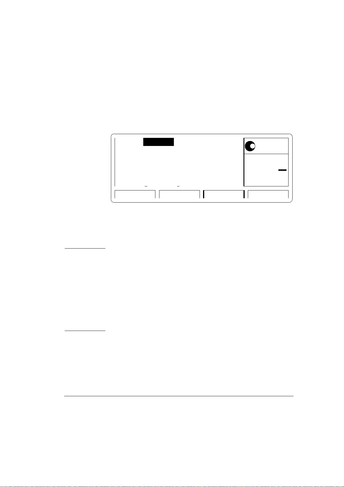
Typical Examples of Displayed Screens
Agilent 81104A/’05A Performance Test
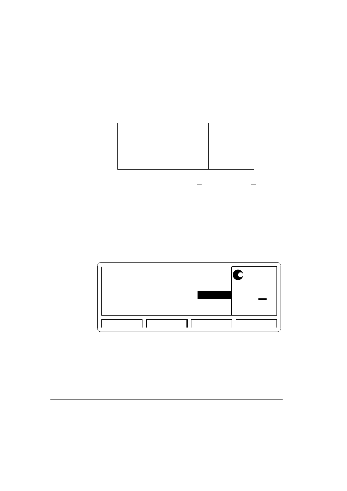
Per 1.000µs Normal
OFF
1
Delay
Width
LeadE
TraiE
The OUTPUT Screen in a Standard Agilent 81104A
Agilent 81104A/’05A Performance Test 7
0ps
100.0ns
3.00ns
=LeadE
OUTPUT PATTERNLIMITSMODE/TRG
Offset
Amplit
50Ω into 50.0
+0.0mV
1.00V
*OFF
ON
Ω
MODIFY

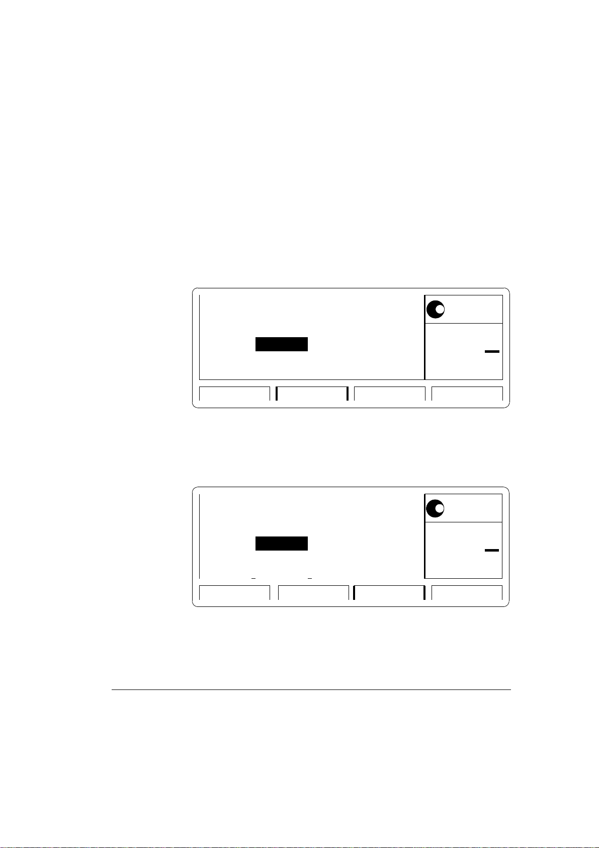
Agilent 81104A/’05A Performance Test
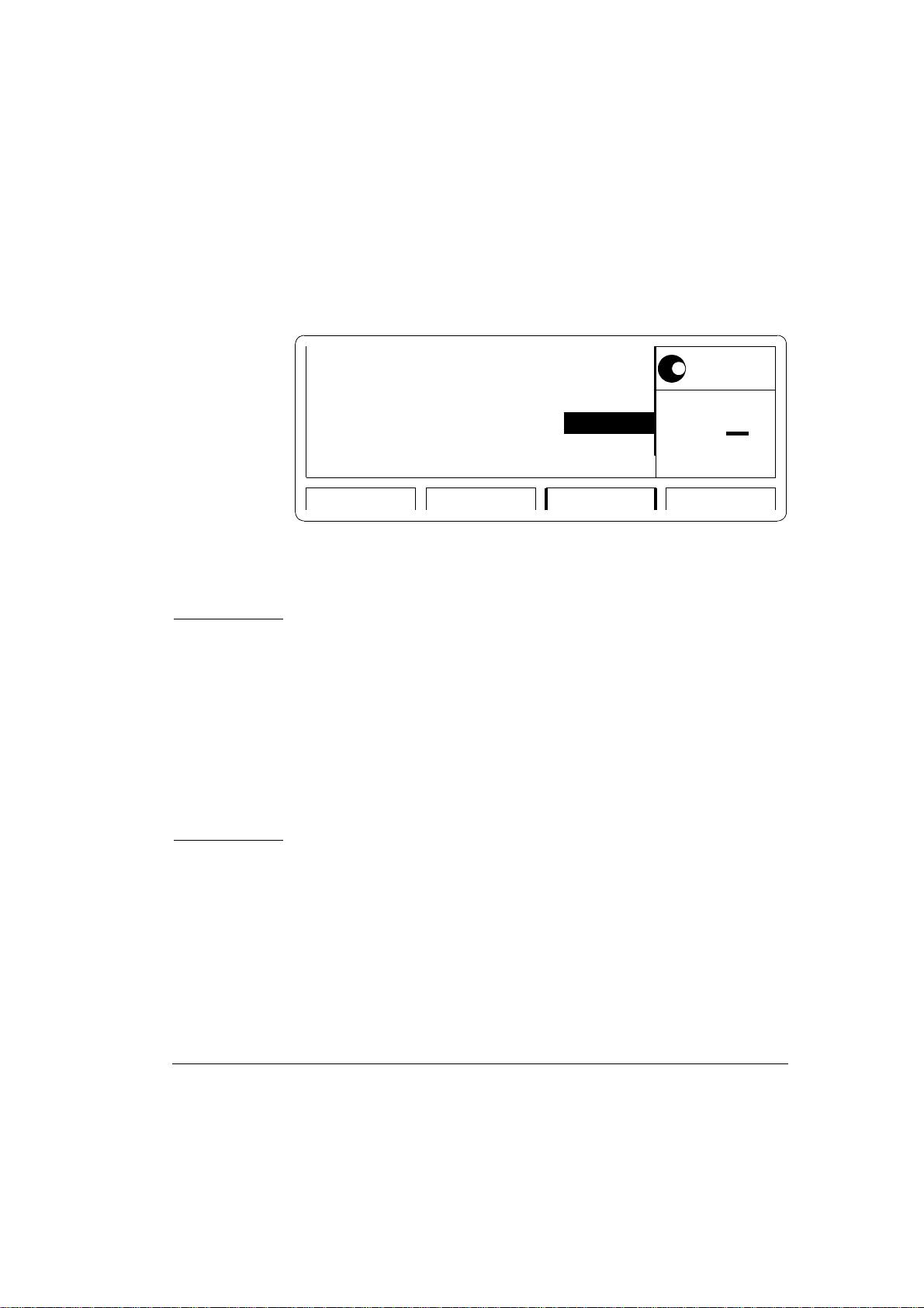
OFF 1.000µs OFF
1
Delay
Width
LeadE
TraiE
The TIMING Screen in an Agilent 81104A with qty 2 of Agilent
81105A
ON Normal Normal ON
Seperate Outputs
High
Low
50Ω into 50.0
Per
0ps
100.0ns
3.00ns
=LeadE
TIMING PATTERNLEVELSMODE/TRG
+2.50V
+0.0mV
Ω
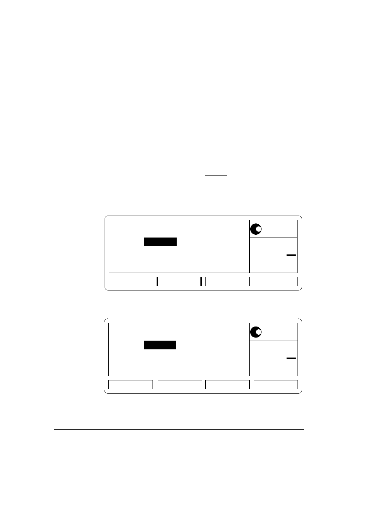
2
Delay 0ps
Width
LeadE
TraiE
100.0ns
3.00ns
=LeadE
21
High +2.50V
Low +0.0mV
50Ω into 50.0
Ω
MODIFY
*Period
Frequency
MODIFY
Set TTL
*High-Low
Offs-Ampl
Set ECL
TIMING PATTERNLEVELSMODE/TRG
The LEVELS Screen in an Agilent 81104A with qty 2 of Agilent
81105A
8 Agilent 81104A/’05A Performance Test

Instrument Serial Numbers
You will need to write the serial numbers of the instrument at the
top of the Test Reports. These can be found as follows:
Press HELP, [SERIAL #]
The Agilent 81104A display lists the instrument's products and
serial number.
The display on your instrument should look similar to this:
Agilent 81104A/’05A Performance Test
FRAME :
Serial No :
81104A 80 MHz
DE38700132
OUTPUTS
Ch1-Bd. :
Ch2-Bd. :
81105A
81105A
The serial number given for the FRAME applies to the Mainframe,
the Power Supply, the Microprocessor Board, and the Timing
Board. The number(s) available of the Output Channel(s) applies
to the installed numbers of outputs and Model Number.
Agilent 81104A/’05A Performance Test 9

Agilent 81104A/’05A Performance Test
Initial Setup of the Agilent 81104A
In the majority of these tests the initial setting up of the instrument
is identical. Therefore, it is described once here, and then referredto where appropriate. In cases where the initial setup differs, an
illustration of the settings is shown.
Set up the Agilent 81104A as follows:
1. Select [MODE/TRG]
• CONTINUOUS PULSES
• Single-Pulses at Out 1 (plus Single-Pulses at Out 2, if
second channel is installed
• Pulse-Period:internal Osc
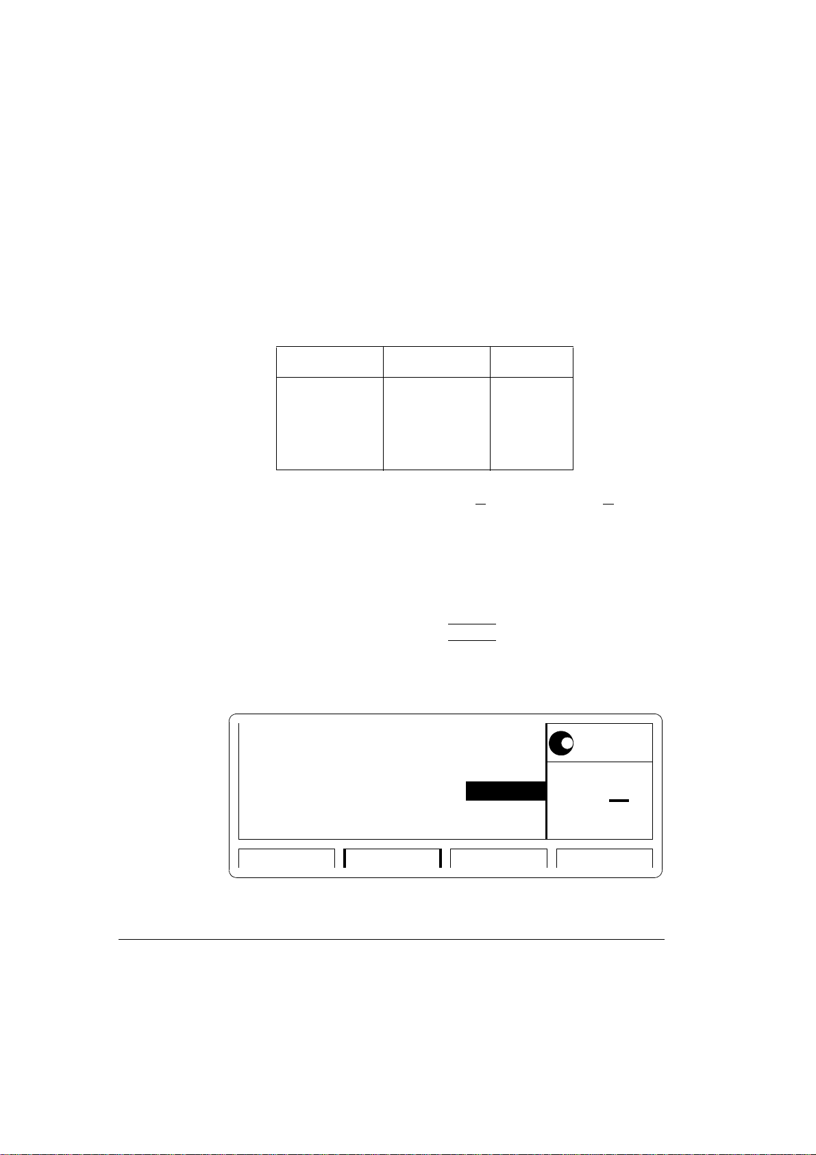
2. If a second output channel is installed, select MORE [CONFIG]
screen and set up as follows:
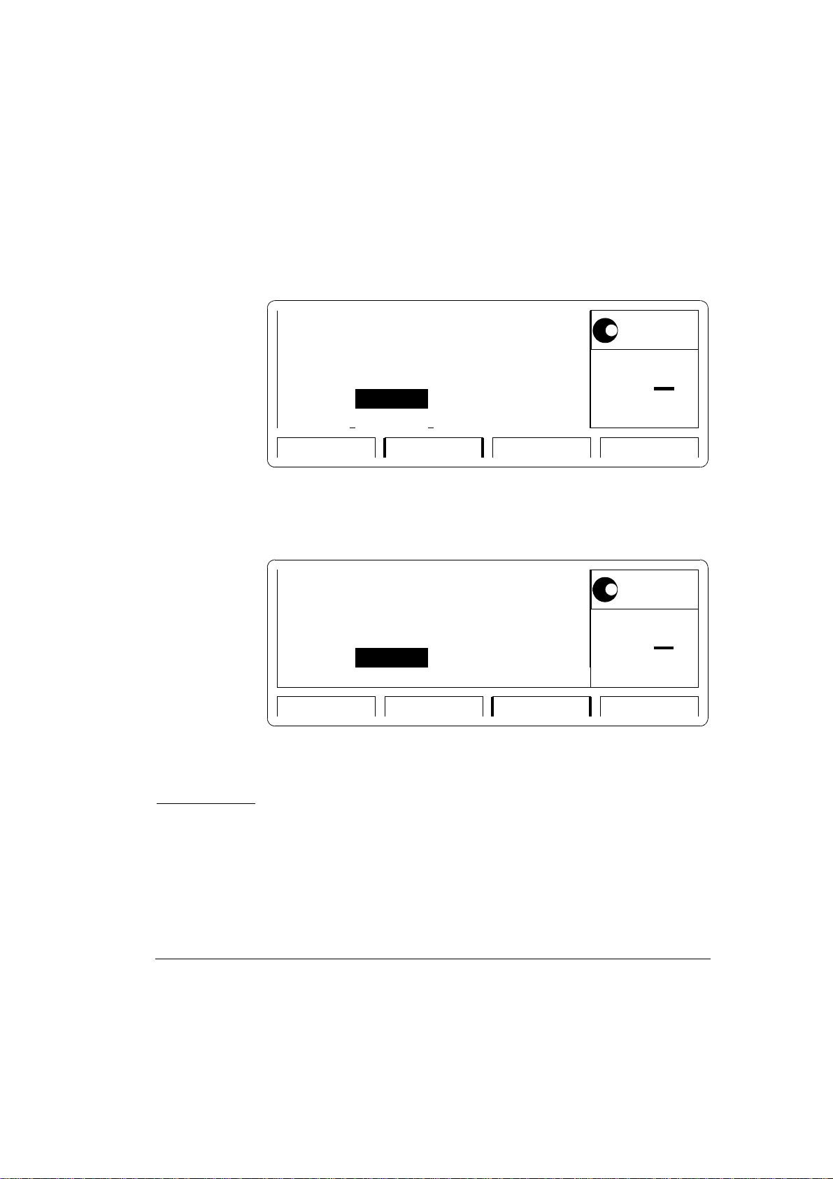
GPIB Address: 10
Perform: Timing Calibration
Group Params by: OUTPUT 1 / 2
PLL-Ref : Internal
TRG-LEV CONFIGMEMCARDLIMITS
CONFIG Screen, Parameters grouped by OUTPUT
10 Agilent 81104A/’05A Performance Test
MODIFY
Selftest
*Calibrate

Agilent 81104A/’05A Performance Test
NOTE: Set-ups are given in all the tests for [OUTPUT 1] and [OUTPUT 2].
If you are testing a single channel instrument set up the [OUTPUT]
screen with the settings given for [OUTPUT 1].
Agilent 81104A/’05A Performance Test 11

Agilent 81104A/’05A Performance Test
Test 1: Period (PLL not active)
Test Specifications
Range 12.5 ns to 999.5 s
Resolution 3.5 digits, best case 5 ps
Accuracy +5%
Equipment Needed
Counter
Cable, 50 Ω, coaxial, BNC
Procedure
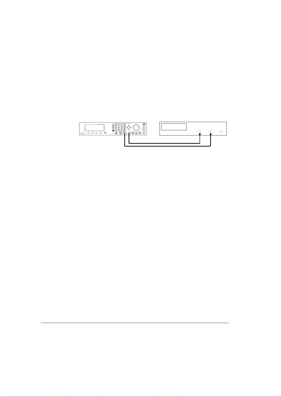
1. Connect the Agilent 81104A to the Counter as shown:
81104A UNDER TEST
80 MHz
81104A
S
Agilent
PULSE-/ PATTERN GENERATOR
TRIG OUT
5334B Counter
Connecting the Agilent 81104A to the Counter
2. Set up the Agilent 81104A as described in "Initial Setup of the
Agilent 81104A"
12 Agilent 81104A/’05A Performance Test
INPUT A C

Agilent 81104A/’05A Performance Test
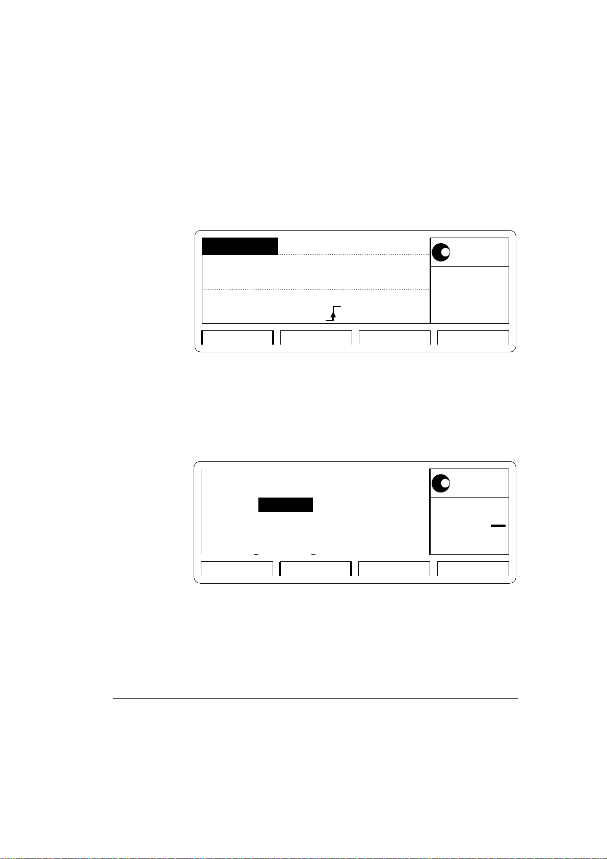
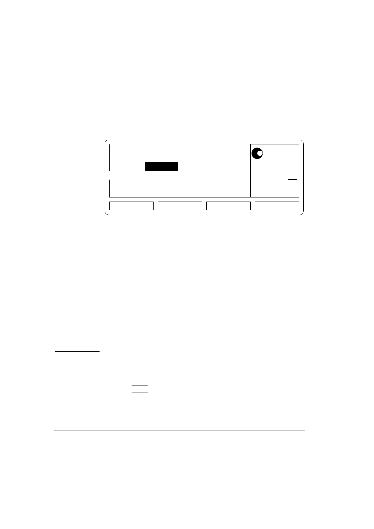
On the Agilent 81104A press MORE and set up [OUTPUT 1] and
[OUTPUT 2] pages as shown in the following illustrations:
Per Normal ON
Delay
DtyCyc
LeadE
TraiE
Configuring Output 1
Per Normal OFF
Delay
DtyCyc
LeadE
TraiE
12.50ns
0ps
50.00%
3.00ns
=LeadE
OUTPUT 1 PATTERNOUTPUT 2MODE/TRG
12.50ns
0ps
50.00%
3.00ns
=LeadE
Offset
Amplit
50Ω into 50.0
Offset
Amplit
50Ω into 50.0
Separate Out2
+0.0mV
1.00V
1
Ω
2
+0.0mV
1.00V
Ω
MODIFY
12.50
ns
MODIFY
12.50
ns
OUTPUT 1 PATTERNOUTPUT 2MODE/TRG
Configuring Output 2
Agilent 81104A/’05A Performance Test 13

Agilent 81104A/’05A Performance Test
NOTE: When you are testing instruments with 2 output channels it is
necessary to:
a. Configure both channels.
b. For Period Test you can switch OFF the channels that are not
being tested.
3. Set the Counter to:
FUNCTION Period A
INPUT A
SENSE
50 Ω
Οn
4. Check the Agilent 81104A period at the following settings:
Period Acceptable Range TR entry
12.50 ns
50.00 ns
99.90 ns
100 ns
500 ns
1 µs
500 µs
500 ms
11.875 ns to 13.125 ns
47.5 ns to 52.5 ns
94.905 ns to 104.895 ns
95 ns to 105 ns
475 ns to 525 ns
950 ns to 1050 ns
475µs to 525 µs
475 ms to 525 ms
1 - 1
1 - 2
1 - 3
1 - 4
1 - 5
1 - 6
1 - 7
1 - 8
14 Agilent 81104A/’05A Performance Test

Agilent 81104A/’05A Performance Test
Test 2: PLL Period
NOTE: This test is only performed if PLL is switched on.
Test Specifications
Range 12.5 ns to 999.5 s
Resolution 4 digits, best case 1 ps
Accuracy + 0.01%
Equipment Needed
Counter Agilent 53132A
Cable, 50 Ω, coaxial, BNC
NOTE: The Agilent 53132A counter is used in frequency mode to meet
the MIL CAL A uncertainty requirements for TAR (Test
Accuracy Ratio) > 4:1.
Procedure
Connect the Agilent 81104A to the counter as follows:
81104A UNDER TEST
80 MHz
81104A
S
Agilent
PULSE-/ PATTERN GENERATOR
TRIG OUT
53132A Counter
CHANNEL 1 2
Connecting Agilent 81104A to the Counter
Agilent 81104A/’05A Performance Test 15
3

Agilent 81104A/’05A Performance Test
5. Set up the Agilent 81104A as described in "Initial Setup of the
Agilent 81104A"
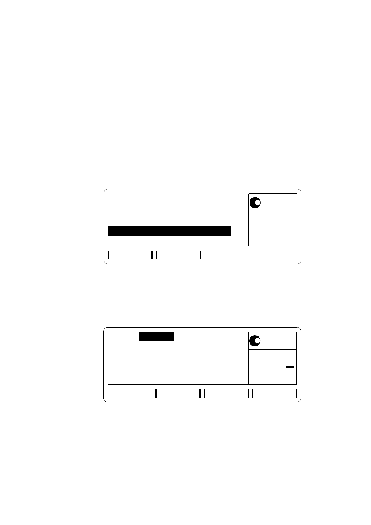
6. Select the [MODE/TRG] screen on the Agilent 81104A and set
up as follows:
CONTINUOUS PULSES
Single-Pulses at Out1
Single-Pulses at Out2
Pulse-Period: internal PLL
TIMING PATTERNLEVELSMODE/TRG
MODIFY
int. OSC
*int. PLL
CLK-IN
The MODE/TRG Screen Setup
7. On the Agilent 81104A set up [OUTPUT 1] and [OUTPUT 2]
pages as shown in the test before!
16 Agilent 81104A/’05A Performance Test

Agilent 81104A/’05A Performance Test
NOTE: When you are testing instruments with 2 output channels it is
necessary to:
a. Configure both channels.
b. For Period Test you can switch OFF the channels that are not
being tested.
8. Set the Counter to measure the frequency at the choosen input
1 / 3
9. Check the Agilent 81104A PLL pulse period at the following
settings:
Period Frequency Acceptable Range TR Entry
12.5 ns
20.00 ns
50.00 ns
100 ns
500 ns
1 µs
50 µs
5 ms
500 ms
5 s
80.000MHz
50 MHz
20 MHz
10 MHz
2 MHz
1 MHz
20 kHz
200 Hz
2 Hz
0.2 Hz
79.002 MHz to 80.008 MHz
49.995 MHz to 50.005 MHz
19.998 MHz to 20.002 MHz
9.999 MHz to 10.001 MHz
1.9998 MHz to 2.0002 MHz
999.9 kHz to 1.0001 MHz
9.998 kHz to 20.002 kHz
199.980 Hz to 200.020 Hz
1.9998 Hz to 2.0002 Hz
0.19998 Hz to 0.20002 Hz
2 - 1
2 - 2
2 - 3
2 - 4
2 - 5
2 - 6
2 - 7
2 - 8
2 - 9
2 - 10
Agilent 81104A/’05A Performance Test 17

Agilent 81104A/’05A Performance Test
Test 3: Width
Test Specifications
Range 6.25 ns to (period - 6.25 ns)
Resolution 3.5 digits, best case 5 ps
Accuracy + 5% + 250 ps
Equipment Needed
Digitizing Oscilloscope with Accessories
Counter
Cable, 50 Ω, coaxial, BNC
Procedure
1. Connect Agilent 81104A to the Scope as shown:
81104A UNDER TEST
81104A
80 MHz
S
Agilent
PULSE-/ PATTERN GENERATOR
TRIG OUT
OUT 1
54121T Frontend
INPUT 1 2 3 4 TRIG
Connecting Agilent 81104A to the Scope
2. Set up the Agilent 81104A as described in "Initial Setup of the
Agilent 81104A"
18 Agilent 81104A/’05A Performance Test
6 dB
Attenuator
with SMA/BNC
Adapter
20 dB

Agilent 81104A/’05A Performance Test
3. On the Agilent 81104A press MORE and set up [OUTPUT 1]
and [OUTPUT 2] pages as shown in the following illustrations:
Per 200 ns Normal ON
Delay
LeadE
TraiE
Configuring Output Screen 1
Per 200 ns Normal OFF
Delay
Width
LeadE
TraiE
0ps
100.0nsWidth
3.00ns
=LeadE
OUTPUT 1 PATTERNOUTPUT 2MODE/TRG
0ps
6.250ns
3.00ns
=LeadE
OUTPUT 1 PATTERNOUTPUT 2MODE/TRG
Offset
Amplit
50Ω into 50.0
Offset
Amplit
50Ω into 50.0
Separate Out2
1
+0.0mV
1.00V
Ω
2
+0.0mV
1.00V
Ω
MODIFY
100.0
ns
MODIFY
6.250
ns
Configuring Output Screen 2
Agilent 81104A/’05A Performance Test 19

Agilent 81104A/’05A Performance Test
NOTE: When you are testing instruments with 2 output channels it is
necessary to:
a. Configure both channels.
b. Switch OFF the channel that is not being tested.
If you then test the other channel:
c. Switch ON the channel you are testing, and switch OFF the
other channel.
4. Set the Digitizing Oscilloscope Agilent 54121T:
• Press AUTOSCALE
• Select the Display menu and set the Number of Averages to 32
• Select the delta V menu and turn the voltage markers On
• Set the preset levels to 50% -50% and press AUTO LEVEL SET
• Select the delta t menu and turn the time markers ON
• Set START ON EDGE = POS 1 and STOP ON EDGE = NEG1
5. Change the oscilloscope timebase to 1 ns/div
6. Change the Agilent 81104A Ch-1 Width to 6.250 ns
7. Center the pulse in the Scope display
8. Press the PRECISE EDGE FIND key for each new Width setting
9. Check the Agilent 81104A pulse width at the following settings:
20 Agilent 81104A/’05A Performance Test

Agilent 81104A/’05A Performance Test
Oscilloscope
Timebase
2 ns/div
2 ns/div
10 ns/div
20 ns/
100 ns
Period Width Acceptable Range TR Entry
200 ns
200 ns
200 ns
1 µs
1 µs
6.25 ns
10.00 ns
50.00 ns
100.0 ns
500.0 ns
5.6875 ns to 6.8125 ns
9.250 ns to 10.750 ns
47.25 ns to 52.75 ns
94.75 ns to 105.25 ns
474.75 ns to 525.25 ns
10. Connect the Agilent 81104A to the Counter as shown:
81104A UNDER TEST
80 MHz
81104A
S
Agilent
PULSE-/ PATTERN GENERATOR
OUT 1
5334B Counter
INPUT A
3 - 1
3 - 2
3 - 3
3 - 4
3 - 5
Connecting Agilent 81104A to the Counter
11. Set the Counter to:
FUNCTION
SENSE
INPUT A
COM A
INPUT B
Agilent 81104A/’05A Performance Test 21
TI A→ B
On
50 Ω
On
50 Ω, negative slope

Agilent 81104A/’05A Performance Test
12. Check the Agilent 81104A width at the following settings:
Period Width Acceptable Range TR Entry
100 µs
10 ms
999 ms
50 µs
5 ms
500ms
47.5 µs to 52.5 µs
4.75 ms to 5.25ms
475 ms to 525 ms
3 - 6
3 - 7
3 - 8
NOTE: Repeat the entire test for the second channel, if it is installed
22 Agilent 81104A/’05A Performance Test

Test 4: Delay
Test Specifications
Range Fixed typical Delay of
Agilent 81104A/’05A Performance Test
EXT INPUT to TRIGGER OUT 12 ns
TRIGGER OUT to OUTPUT 1/2 15 ns
Variable Delay:
0 ns to (period - 12.5 ns)
Resolution
Accuracy
Equipment Needed
Digitzing Oscilloscope with Accessories
Pulse Generator
Counter
Cable, 50 Ω, coaxial, BNC
Procedure
Connect Agilent 81104A to the Scope as shown:
3.5 digits, best case 5 ps
±5% ±0.5 ns
Agilent 81104A/’05A Performance Test 23

Agilent 81104A/’05A Performance Test
81104A UNDER TEST
80 MHz
81104A
S
Agilent
PULSE-/ PATTERN GENERATOR
8110A Pulse Generator
TRIG
OUT 1
OUT
EXT.
TRIG
OUT 1
OUT
IN
54121T Frontend
INPUT 1 2 3 4 TRIG
Attenuator
3 x 20 dB
with SMA/BNC
Adaptor
Connecting Agilent 81104A to the Scope
13. Set up the Agilent 81104A as described in "Initial Setup of the
Agilent 81104A"
14. Set the Pulse Generator to:
Period
Width
Amplitude
Offset
Output
1 µs
100 ns
1 V
+1.0 V
Enable
15. Select the [MODE/TRG] screen on the Agilent 81104A and set
up as follows:
24 Agilent 81104A/’05A Performance Test

Agilent 81104A/’05A Performance Test
PULSES
TRIGGERED
Single-Pulses at Out1
Single-Pulses at Out2
Trg'd by: EXT-IN
TIMING PATTERNLEVELSMODE/TRG
MODIFY
Continous
*Triggered
Gated
Ext-Width
The TRG MODE Screen Setup
16. On the Agilent 81104A press MORE and set up [TRIG-LEV]
page as shown:
+1.0V 50
EXT-IN: Threshold
CLK-IN: Threshold +1.0V 50
TRIGGER-OUT: TTL
STROBE-OUT : TTL
TRG-LEV CONFIGMEMCARDLIMITS
The TRG-LEV Screen Setup
Agilent 81104A/’05A Performance Test 25
Ω
Ω
Set TTL
Set ECL
*Voltage
MODIFY

Agilent 81104A/’05A Performance Test
17. On the Agilent 81104A set up [OUTPUT 1] and [OUTPUT 2]
pages as shown in the following illustrations:
Per -------- Normal ON
Delay
Width
LeadE
TraiE
Configuring Output Screen 1
Per -------- Normal ON
Delay
Width
LeadE
TraiE
0ps
100ns
3.00ns
=LeadE
0ps
100ns
3.00ns
=LeadE
Offset
Amplit
50Ω into 50.0
OUTPUT 1 PATTERNOUTPUT 2MODE/TRG
Offset
Amplit
50Ω into 50.0
1
+0.0mV
1.00V
Ω
1
+0.0mV
1.00V
Ω
MODIFY
0
ps
MODIFY
0
ps
OUTPUT 1 PATTERNOUTPUT 2MODE/TRG
Configuring Output Screen 2
26 Agilent 81104A/’05A Performance Test

Agilent 81104A/’05A Performance Test
NOTE: When you are testing instruments with 2 output channels it is
necessary to:
a. Configure both channels.
b. Switch OFF the channel that is not being tested
If you then test the other channel:
c. Switch ON the channel you are testing, and switch OFF the
other channel.
18. Set the Digitizing Oscilloscope Agilent 54121T:
• Press AUTOSCALE
• Set timebase to TIME/DIV = 10 ns/div
• Center the positive-going edges of the two signals
• Select the Display menu and set the screen function to single; set the
number of averages to 32
• Select the Delta V menu and turn the voltage markers ON and assign
marker 1 to channel 3 and marker 2 to channel 4
• Set Preset levels to 50% - 50% and press AUTO LEVEL SET
• Select the Delta t menu and turn the time markers ON
• Set START ON EDGE= POS1 and STOP ON EDGE= POS 1
• Press the PRECISE EDGE FIND key
19. Check the Agilent 81104A delay at the following settings:
Agilent 81104A/’05A Performance Test 27

Agilent 81104A/’05A Performance Test
NOTE: Record the value of the fixed delay and subtract it from the other
readings.
Oscilloscope Timebase Delay Acceptable Range TR Entry
10 ns/div
10 ns/div
20 ns/div
20 ns/div
50 ns/div
200 ns/div
0 ps
5.000 ns
10.00 ns
50.00 ns
100.0 ns
500.0 ns
fixed Delay of TRIG OUT to OUT 1/2:
15 ns typ.
4.25 ns to 5.75 ns
9.000 ns to 11.00 ns
47.00 ns to 53.00 ns
94.50 ns to 105.50 ns
474.50 ns to 525.50 ns
4 - 1
4 - 2
4 - 3
4 - 4
4 - 5
4 - 6
20. Connect the Agilent 81104A to the Counter as follows:
81104A UNDER TEST
80 MHz
81104A
S
Agilent
PULSE-/ PATTERN GENERATOR
TRIG OUT
OUT 1
5334B Counter
INPUT A INPUT B
Connecting Agilent 81104A to the Counter
21. Set Agilent 81104A to Continuous-Pulses on the
MODE/TRG screen
22. Set the Counter to:
28 Agilent 81104A/’05A Performance Test

Agilent 81104A/’05A Performance Test
FUNCTION TI
SENSE
INPUT A
INPUT B
A → B
On
50 Ω
50 Ω
23. Check the Agilent 81104A delay at the following settings:
NOTE: Subtract the fixed delay from the other readings
Period Delay Acceptable Range TR Entry
100 µs
10 ms
999 ms
NOTE: Repeat the entire test for the second channel, if it is installed.
50 µs
5 ms
500ms
47.5 µs to 52.5 µs
4.75 ms to 52.5ms
475 ms to 525 ms
4 - 7
4 - 8
4 - 9
Agilent 81104A/’05A Performance Test 29

Agilent 81104A/’05A Performance Test
Test 5: Double Pulse Delay
Test Specifications
Range 12.5ns to
(period - width - 6.25 ns)
Resolution
Accuracy
Equipment Needed
Digitizing Oscilloscope with Accessories
Counter
Cable, 50 Ω, coaxial, BNC
Procedure
1. Connect Agilent 81104A to the Scope as shown:
81104A UNDER TEST
S
Agilent
81104A
80 MHz
PULSE-/ PATTERN GENERATOR
TRIG OUT
OUT 1
3.5 digits, best case 5 ps
± 5% ± 250 ps
54121T Frontend
INPUT 1 2 3 4 TRIG
6 dB
Attenuator
with SMA/BNC
Adapter
20 dB
Connecting Agilent 81104A to the Scope
30 Agilent 81104A/’05A Performance Test

Agilent 81104A/’05A Performance Test
2. Set up the Agilent 81104A as described in "Initial Setup of the
Agilent 81104A"
3. Select the [MODE/TRG] screen on the Agilent 81104A and set
up Output 1 and Output 2 as follows:
CONTINUOUS PULSES
MODIFY
Double-Pulses at Out1
Double-Pulses at Out2
Single
* Double
Pulse-Period: internal Osc
TIMING PATTERNLEVELSMODE/TRG
The MODE/TRG Screen Setup
4. On the Agilent 81104A set up [OUTPUT 1] and [OUTPUT 2]
pages as shown in the following illustrations:
Agilent 81104A/’05A Performance Test 31

Agilent 81104A/’05A Performance Test
Per Normal ON
Width
LeadE
TraiE
Configuring Output Screen 1
Per Normal OFF
Width
LeadE
TraiE
200.0ns
12.50nsDblDel
6.250ns
3.00ns
=LeadE
OUTPUT 1 PATTERNOUTPUT 2MODE/TRG
200.0ns
12.50nsDblDel
6.250ns
3.00ns
=LeadE
Offset
Amplit
50Ω into 50.0
Offset
Amplit
50Ω into 50.0
Separate Out2
+0.0mV
1.00V
+0.0mV
1.00V
1
12.50
Ω
ns
2
12.50
Ω
ns
MODIFY
MODIFY
OUTPUT 1 PATTERNOUTPUT 2MODE/TRG
Configuring Output Screen 2
32 Agilent 81104A/’05A Performance Test

Agilent 81104A/’05A Performance Test
NOTE: When you are testing instruments with 2 output channels it is
necessary to:
a. Configure both channels.
b. Switch OFF the channel that is not being tested
If you then test the other channel:
c.Switch ON the channel you are testing, and switch OFF the
other channel.
5. Set the Digitizing Oscilloscope Agilent 54121T:
• Press AUTOSCALE
• Center the double pulse signal
• Select the Display menu and set the Number of Averages to 32
• Select the Delta V menu and turn the Voltage markers On
• Set Preset Levels = 50% -50% and press AUTO LEVEL SET
• Select the Delta t menu and turn the Time markers On
• Set START ON EDGE = POS1 and STOP ON EDGE = POS2
6. Press the PRECISE EDGE FIND key for each new Double
Delay setting
7. Check the Agilent 81104A double delay at the following settings:
Oscilloscope Timebase Double Delay Acceptable Range TR Entry
2 ns/div
10 ns/div
20 ns/div
12.50 ns
50.00 ns
100.0 ns
11.625 ns to 13.375 ns
47.25 ns to 52.75 ns
94.75 ns to 105.25 ns
5 - 1
5 - 2
5 - 3
Agilent 81104A/’05A Performance Test 33
Agilent 81104A/’05A Performance Test
8. Connect the Agilent 81104A to the Counter as shown:
81104A UNDER TEST
80 MHz
81104A
S
Agilent
PULSE-/ PATTERN GENERATOR
TRIG OUT
OUT 1
5334B Counter
INPUT A ARM
Connecting Agilent 81104A to the Counter
9. Set the Counter to:
FUNCTION
INPUT A
SENSE
Period A
50 Ω
On
( EXT ARM
SELECT
a. Start (ST): leading edge
b. Stop (SP): trailing edge )
10. Set up the Agilent 81104A as described in "Initial Setup of the
Agilent 81104A"
11. Select the[MODE/TRG]screen on the Agilent 81104A and set up
as follows;
34 Agilent 81104A/’05A Performance Test
Agilent 81104A/’05A Performance Test
PULSES
TRIGGERED
Double-Pulses at Out1
Double-Pulses at Out2
Trg'd by: MANKey
OUTPUT 1 PATTERNOUTPUT 2MODE/TRG
The MODE/TRG Screen Setup
12. On the Agilent 81104A set up [OUTPUT 1] and [OUTPUT 2]
pages as shown in the following illustrations:
MODIFY
*MAN Key
EXT INPUT
PLL
Per -------- Normal ON
DblDel
Width
LeadE
TraiE
Configuring Output Screen 1
Agilent 81104A/’05A Performance Test 35
500.0ms
20.00ns
3.00ns
=LeadE
Offset
Amplit
50Ω into 50.0
OUTPUT 1 PATTERNOUTPUT 2MODE/TRG
+0.0mV
1.00V
1
500.0
Ω
ms
MODIFY
Agilent 81104A/’05A Performance Test
Per -------- Normal OFF
2
DblDel
Width
LeadE
TraiE
Configuring Output Screen 2
NOTE: When you are testing instruments with 2 output channels it is
necessary to:
a. Configure both channels.
b. Switch OFF the channel that is not being tested
If you then test the other channel:
100.0ns
20.00ns
3.00ns
=LeadE
OUTPUT 1 PATTERNOUTPUT 2MODE/TRG
Offset
Amplit
50Ω into 50.0
Separate Out2
+0.0mV
1.00V
Ω
MODIFY
100.0
ns
c. Switch ON the channel you are testing, and switch OFF the
other channel.
13. Check the Agilent 81104A double pulse delay at the following
settings:
Press MAN to check each new setting!
36 Agilent 81104A/’05A Performance Test

Agilent 81104A/’05A Performance Test
Double Delay Acceptable Range TR Entry
500 ms
1 s
475 ms to 525 ms
950.00 ms to 1050.00 ms
5 - 4
5 - 5
NOTE: Repeat the entire test for the second channel, if it is installed.
Agilent 81104A/’05A Performance Test 37

Agilent 81104A/’05A Performance Test
Test 6: Jitter
The following tests are required:
1. Period Jitter
a. Internal Oscillator
b. Internal PLL
2. Width Jitter
3. Delay Jitter
Test 6.1a: Period Jitter, Internal Oscillator
Test Specifications
RMS-Jitter 0.01% + 15 ps
Equipment Needed
Digitizing Oscilloscope with Accessories
Delay Line (22 ns)
Power Splitter
Cable, 50 Ω, coaxial, BNC
Cable, SMA
Procedure
1. Connect Agilent 81104A to the Scope as shown:
38 Agilent 81104A/’05A Performance Test

Agilent 81104A/’05A Performance Test
81104A UNDER TEST
80 MHz
81104A
S
Agilent
PULSE-/ PATTERN GENERATOR
BNC - SMA
Adapter
OUT 1
INPUT 1
54121T Frontend
SMA - SMA
Adapter
SMA Cable
2
SMA Cable
54008A Delay Line
4
3
INPUT
TRIG
POWER SPLITTER
OUTPUT
11667B
Equipment Set-up for Jitter Test
2. Set up the Agilent 81104A as described in "Initial Setup of the
Agilent 81104A"
3. On the Agilent 81104A set up [OUTPUT 1] and [OUTPUT 2]
pages as shown in the following illustrations:
Per Normal ON
50.00ns
MODIFY
Delay1 0ps
Width
LeadE
TraiE
25.00ns
3.00ns
=LeadE
Offset
Amplit
50Ω into 50.0
OUTPUT 1 PATTERNOUTPUT 2MODE/TRG
Configuring Output Screen 1
Agilent 81104A/’05A Performance Test 39
+500mV
1.00V
Ω
50.00
ns

Agilent 81104A/’05A Performance Test
Per Normal OFF
Delay
Width
LeadE
TraiE
Configuring Output Screen 2
NOTE: When you are testing instruments with 2 output channels it is
50.00ns
2
0ps
25.00ns
3.00ns
=LeadE
necessary to:
a. Configure both channels.
b. Switch OFF the channel that is not being tested
If you then test the other channel:
Offset
Amplit
50Ω into 50.0
Separate Out2
OUTPUT 1 PATTERNOUTPUT 2MODE/TRG
+500mV
1.00V
Ω
50.00
ns
MODIFY
c. Switch ON the channel you are testing, and switch OFF the
other channel.
4. Set the Digitizing Oscilloscope Agilent 54121T:
• Press AUTOSCALE
• Select the Display menu and set the Number of Averages to 64
• Select the Channel menu and set the Attenuation factor of channel 2
to 2
40 Agilent 81104A/’05A Performance Test

Agilent 81104A/’05A Performance Test
• Set the VOLTS/DIV of channel 2 to 10 mV/div
• Set OFFSET to 500 mV
• Select the Timebase menu and set the TIME/DIV to 100 ps/div
• Center the first positive-going edge of the signal (approximate Delay
= 29ns)
• Select the Delta V menu and turn the V markers On
• Set the Marker 1 Position to 490 mV and the Marker 2 Position to
500 mV
• Select the Delta t menu and turn the T Markers On
• Set START ON EDGE = POS1 and STOP ON EDGE = POS1
• Press the PRECISE EDGE FIND key
5. RECORD the delta t reading. This is the rise time of the refer-
ence signal within a 1% amplitude window of the signal connected to Input 2. This value is needed later to calculate the
correct jitter.(delta.t.up)
6. Select the Timebase menu and center the second positive-
going edge of the signal (approximate Delay = 79 ns)
7. Press MORE and HISTOGRAM
• Select the Window submenu and set:
• Source is channel 2
• Choose the Time Histogram
• Press WINDOW MARKER 1 and set it to 490 mV
• Press WINDOW MARKER 2 and set it to 500 mV
Agilent 81104A/’05A Performance Test 41

Agilent 81104A/’05A Performance Test
8. Select the Acquire submenu, set the Number of Samples to
1000 and press START ACQUIRING
9. After the data for the time histogram has been acquired (#
Samples = 100%), select the Result submenu.
10. Press ΜΕΑΝ and SIGMA. RECORD the values of sigma
11. The RMS-jitter is calculated as follows:
RMS - jitter =
6sigma - delta.t.up
6
12. The RMS-jitter for period of 50 ns is 20 ps. Enter the result in
the Test Report as TR entry 6.1a - 1
13. Set the Agilent 81104A period to 500 ns
14. Repeat steps 6 to 11
NOTE: TIME/DIV = 200 ps/div; approximate Delay = 529 ns
15. The RMS-jitter for period of 500 ns is 65 ps. Enter the result in
the Test Report as TR entry 6.1a - 2
42 Agilent 81104A/’05A Performance Test

Test 6.1b: Period Jitter, Internal PLL
Test Specifications
RMS-Jitter 0.001% + 15 ps
Equipment Needed
Digitizing Oscilloscope with Accessories
Delay Line (22 ns)
Power Splitter
Cable, 50 Ω, coaxial, BNC
Cable, SMA
Procedure
1. Connect Agilent 81104A to the Scope as shown.
Agilent 81104A/’05A Performance Test
54750A + 54751A
81104A UNDER TEST
81104A
80 MHz
S
Agilent
PULSE-/ PATTERN GENERATOR
BNC/SMA
Adapter
OUT 1
SMA Cable
6 dB Attenuator
54008A Delay Line
INPUT
OUTPUT
POWER SPLITTER
11667B
TRIG
SMA Cable
Equipment Set-up for Jitter Test using the Agilent 54750A +
54751A
Using the Agilent 54121T the Set-up is the same as before.
Agilent 81104A/’05A Performance Test 43
Agilent 81104A/’05A Performance Test
2. Set up the Agilent 81104A as described in "Initial Setup of the
Agilent 81104A"
3. Select the [MODE/TRG] screen on the Agilent 81104A and set
up as follows:
CONTINUOUS PULSES
Single-Pulses at Out1
Single-Pulses at Out2
Pulse-Period: internal PLL
TIMING PATTERNLEVELSMODE/TRG
The TRG MODE Screen Setup
4. On the Agilent 81104A set up [OUTPUT 1] and [OUTPUT 2]
pages as shown in the following illustrations:
Per Normal ON
20.00ns
1
Delay
Width
LeadE
TraiE
0ps
10.00ns
3.00ns
=LeadE
Offset
Amplit
50Ω into 50.0
+500mV
1.00V
Ω
MODIFY
int. OSC
*int. PLL
CLK-IN
MODIFY
20.00
ns
OUTPUT 1 PATTERNOUTPUT 2MODE/TRG
Configuring Output Screen 1
44 Agilent 81104A/’05A Performance Test
Agilent 81104A/’05A Performance Test
Per Normal OFF
Delay
Width
LeadE
TraiE
Configuring Output Screen 2
NOTE: When you are testing instruments with 2 output channels it is
20.00ns
2
0ps
10.00ns
3.00ns
=LeadE
OUTPUT 1 PATTERNOUTPUT 2MODE/TRG
necessary to:
a. Configure both channels.
b. Switch OFF the channel that is not being tested
If you then test the other channel:
Offset
Amplit
50Ω into 50.0
Separate Out2
+500mV
1.00V
20.00
Ω
ns
MODIFY
c. Switch ON the channel you are testing, and switch OFF the
other channel.
5. Set the Digitizing Oscilloscope Agilent 54121T:
• Press AUTOSCALE
• Select the Display menu and set the Number of Averages to 64
• Select the Channel menu and set the Attenuation factor of channel
2 to 2
Agilent 81104A/’05A Performance Test 45

Agilent 81104A/’05A Performance Test
• Set the VOLTS/DIV of channel 2 to 10 mV/div
• Set OFFSET to 500mV
• Select the Timebase menu and set the TIME/DIV to 100 ps/div
• Center the first positive-going edge of the signal (approximate Delay
= 29 ns)
• Select the Delta V menu and turn the V markers On
• Set the Marker 1 Position to 490 mV and the Marker 2 Position
to 500mV
• Select the Delta t menu and turn the T Markers On
• Set START ON EDGE = POS1 and STOP ON EDGE = POS1
• Press the PRECISE EDGE FIND key
6. RECORD the delta t reading. This is the rise time of the refer-
ence signal within a 1% amplitude window of the signal connected to Input 2. This value is needed later to calculate the
correct jitter. (delta.t.up)
7. Select the Timebase menu and center the second positive-
going edge of the signal (approximate Delay = 53 ns)
8. Press MORE and HISTOGRAM
• Select the Window submenu and set:
• Source is channel 2
• Choose the Time Histogram
• Press WINDOW MARKER 1 and set it to 490 mV
• Press WINDOW MARKER 2 and set it to 500 mV
46 Agilent 81104A/’05A Performance Test

Agilent 81104A/’05A Performance Test
9. Select the Acquire submenu, set the Number of Samples to
1000 and press START ACQUIRING
10. After the data for the time histogram has been acquired (#
Samples = 100%), select the Result submenu.
11. Press MEAN and SIGMA. RECORD the values of sigma
12. The RMS-jitter is calculated as follows:
RMS - jitter =
6sigma-delta.t.up
6
13. The RMS-jitter for period of 20 ns is 15.2 ps. Enter the result
in the Test Report as TR entry 6.1b - 1
NOTE: See the Agilent54750A User’s Guide / Service Guide to get the
info needed to do the Jitter Test using this scope.
Agilent 81104A/’05A Performance Test 47

Agilent 81104A/’05A Performance Test
Test 6.2: Width Jitter (PLL not active)
Test Specifications
RMS-Jitter 0.01% + 15 ps
Equipment Needed
Digitizing Oscilloscope with Accessories
Delay Line (22 ns)
Power Splitter
Cable, 50 Ω, coaxial, BNC
Cable, SMA
Procedure
1. Connect Agilent 81104A to the Scope as shown:
81104A UNDER TEST
80 MHz
81104A
S
Agilent
PULSE-/ PATTERN GENERATOR
INPUT 1
2
54121T Frontend
SMA - SMA
Adapter
SMA Cable
BNC - SMA
Adapter
OUT 1
Equipment Set-up for Jitter Test
2. Set up the Agilent 81104A as described in "Initial Setup of the
Agilent 81104A"
48 Agilent 81104A/’05A Performance Test
SMA Cable
54008A Delay Line
4
3
INPUT
TRIG
POWER SPLITTER
OUTPUT
11667B
Agilent 81104A/’05A Performance Test
3. On the Agilent 81104A set up [OUTPUT 1] and [OUTPUT 2]
pages as shown in the following illustrations:
Per 1.000µs Normal ON
Delay
Width
LeadE
TraiE
Configuring Output Screen 1
Per 1.000µs Normal OFF
Delay2 0ps
Width
LeadE
TraiE
0ps
6.250ns
3.00ns
=LeadE
OUTPUT 1 PATTERNOUTPUT 2MODE/TRG
6.250ns
3.00ns
=LeadE
OUTPUT 1 PATTERNOUTPUT 2MODE/TRG
Offset
Amplit
50Ω into 50.0
Offset
Amplit
50Ω into 50.0
Separate Out2
1
+500mV
1.00V
Ω
+500mV
1.00V
Ω
MODIFY
6.250
ns
MODIFY
6.250
ns
Configuring Output Screen 2
Agilent 81104A/’05A Performance Test 49

Agilent 81104A/’05A Performance Test
NOTE: When you are testing instruments with 2 output channels it is
necessary to:
a. Configure both channels.
b. Switch OFF the channel that is not being tested
If you then test the other channel:
c. Switch ON the channel you are testing, and switch OFF the
other channel.
4. Set the Digitizing Oscilloscope Agilent 54121T:
• Press AUTOSCALE
• Select the Display menu and set the Number of Averages to 128
• Select the Channel menu and set the Attenuation factor of channel 2
to 2
• Set the VOLTS/DIV 500 mV
• Select the Timebase menu and set the TIME/DIV to 10 ps/div
• Center the first negative-going edge of the signal (approximate Delay
= 33.8 ns)
• Select the Delta V menu and turn the V markers On
• Set the Marker 1 Position to 500 mV and the Marker 2 Position to
490 mV
• Select the Delta t menu and turn the T Markers On
• Set START ON EDGE = NEG1 and STOP ON EDGE = NEG1
• Press the PRECISE EDGE FIND key
50 Agilent 81104A/’05A Performance Test

Agilent 81104A/’05A Performance Test
5. RECORD the delta t reading. This is the fall time of the referencesignal within a 1% amplitude window of the signal connected to Input 2. This value isneeded later to calculate the
correct jitter. (delta.t.dn)
6. Set the Agilent 81104A Pulse Width to 50 ns
7. Select the Timebase menu and center the first negative-going
edge of the signal (approximate Delay = 80.5 ns)
8. Press MORE and HISTOGRAM
9. Select the Window submenu and set:
• Source is channel 2
• Choose the Time Histogram
• Press WINDOW MARKER 1 and set it to 500 mV
• Press WINDOW MARKER 2 and set it to 490 mV
10. Select the Acquire submenu, set the Number of Samples to
1000 and press START ACQUIRING
11. After the data for the time histogram has been acquired (#
Samples = 100%), select the Result submenu.
12. Press MEAN and SIGMA. RECORD the value of sigma
13. The RMS-jitter is calculated as follows:
Agilent 81104A/’05A Performance Test 51

Agilent 81104A/’05A Performance Test
RMS - jitter =
6 sigma - delta.t.dn
6
14. The RMS-jitter for pulse width of 50 ns is 20 ps. Enter the
result in the Test Report as TR entry 6.2 - 1
15. Set the Agilent 81104A for pulse width of 500ns
16. Repeat steps 7 to 13
NOTE: TIME/DIV = 100ps/div. Approximate delay = 530 ns
17. The RMS-jitter for pulse width of 500 ns is 65 ps. Enter the
result in the Test Report as TR entry 6.2 - 2
NOTE: Repeat the entire test for the second channel, if it is installed.
52 Agilent 81104A/’05A Performance Test

Test 6.3: Delay Jitter (PLL not active)
Test Specifications
RMS-Jitter 0.01% + 15 ps
Equipment Needed
Digitizing Oscilloscope with Accessories
Procedure
1. Connect Agilent 81104A to the Scope as shown:
Agilent 81104A/’05A Performance Test
81104A UNDER TEST
80 MHz
81104A
S
Agilent
PULSE-/ PATTERN GENERATOR
TRIG OUT
OUT 1
54121T Frontend
INPUT 1 2 3 4 TRIG
6 dB
Attenuator
with SMA/BNC
Adapter
20 dB
Equipment Set-up for Delay Jitter Test
2. For calculating the RMS-jitter, the rise time of the reference
signal within a 1% amplitude window is required. If this value
Agilent 81104A/’05A Performance Test 53
Agilent 81104A/’05A Performance Test
is not already measured in the Period Jitter test, then perform
the first 6 steps of the Period Jitter test.
3. Set up the Agilent 81104A as described in "Initial Setup of the
Agilent 81104A"
4. On the Agilent 81104A press MORE and set up [OUTPUT 1]
and [OUTPUT 2] pages as shown in the following illustrations:
Per 1.000µs Normal ON
Delay
LeadE
TraiE
Configuring Output Screen 1
Per 1.000µs Normal OFF
Delay
LeadE
TraiE
50.00ns
50.00nsWidth
3.00ns
=LeadE
OUTPUT 1 PATTERNOUTPUT 2MODE/TRG
50.00ns
50.00nsWidth
3.00ns
=LeadE
OUTPUT 1 PATTERNOUTPUT 2MODE/TRG
Offset
Amplit
50Ω into 50.0
Offset
Amplit
50Ω into 50.0
Separate Out2
1
+500mV
1.00V
Ω
2
+500mV
1.00V
Ω
MODIFY
50.00
ns
MODIFY
50.00
ns
Configuring Output Screen 2
54 Agilent 81104A/’05A Performance Test

Agilent 81104A/’05A Performance Test
NOTE: When you are testing instruments with 2 output channels it is
necessary to:
a.Configure both channels.
b. Switch OFF the channel that is not being tested
If you then test the other channel:
c. Switch ON the channel you are testing, and switch OFF the
other channel.
5. Set the Digitizing Oscilloscope Agilent 54121T:
• Press AUTOSCALE
• Select the Display menu and set the Number of Averages to 64
• Set the VOLTS/DIV = 10 mV/div
• Set OFFSET to 500 mV
• Select the Timebase menu and set the TIME/DIV to 100 ps/div
• Center the first positive-going edge of the signal (approximate Delay
= 65 ns)
6. Press MORE and HISTOGRAM
7. Select the Window submenu and press WINDOW MARKER
1 and set it to 490 mV
8. Press WINDOW MARKER 2 and set it to 500 mV
9. Select the Acquire submenu, set the Number of Samples to
1000 and press START ACQUIRING
10. After the delta for the time histogram has been acquired (#
Samples = 100%), select the Result submenu.
11. Press MEAN and SIGMA. RECORD the values of sigma!
Agilent 81104A/’05A Performance Test 55

Agilent 81104A/’05A Performance Test
12. The RMS-jitter is calculated as follows:
RMS - jitter =
6
13. The RMS-jitter for delay of 50 ns is 20 ps. Enter the result in
the Test Report as TR entry 6.3 - 1
14. Set Agilent 81104A for delay of 500 ns
15. Repeat steps 9 to 12
6sigma - delta.t.up
NOTE: TIME/DIV = 100 ps/div. Approximate delay = 515 ns
16. The RMS jitter for delay of 500 ns is 65 ps. Enter the result in
the Test Report as TR entry 6.3 - 2
NOTE: Repeat the entire test for the second channel, if it is installed.
56 Agilent 81104A/’05A Performance Test

Test 7: High and Low Levels
The following tests are required:
1. High level from 50Ω into 50Ω
2. Low level from 50Ω into 50Ω
3. High level from 1KΩ into 50Ω
4. Low level from 1KΩ into 50Ω
Test Specifications
Source Impedance 50 Ω 1 KΩ
High Level -9.90 V to +10.0 V -19.8 V to +20.0 V
Low Level -10.0 V to +9.9 V -20.0 V to +19.8 V
Amplitude 0.10 Vpp to 10.0 Vpp 0.20 Vpp to 20.0 Vpp
Agilent 81104A/’05A Performance Test
Load Impedance 50 Ω
Equipment Needed
1. Digitizing Voltmeter (DVM)
2. 50 Ω Feedthrough Termination, 0.1%, 10 W Adapter.
3. BNC to dual banana plug (1251-2277)
4. Cable, 50 Ω, coaxial, BNC
Procedure
Connect Agilent 81104A to the DVM as shown:
Level Resolution 10 mV 20 mV
Level Accuracy + 3% of ampl + 75 mV + 5% of ampl + 150 mV
for amplitude ≤ 19V
Agilent 81104A/’05A Performance Test 57

Agilent 81104A/’05A Performance Test
81104A UNDER TEST
80 MHz
81104A
S
Agilent
PULSE-/ PATTERN GENERATOR
3458A DVM
EXT.
TRIGGER
INPUT
BNC-DUAL
BANANA
TRIG OUT
OUT 1
Connecting the DVM for High and Low Levels Tests
Test 7.1: High Level, 50 Ohms into 50 Ohms
1. Set up the Agilent 81104A as described in "Initial Setup of the
Agilent 81104A"
2. On the Agilent 81104A press MORE and set up [OUTPUT 1]
and [OUTPUT 2] pages as shown in the following illustrations:
Per 100.0ms Normal ON
Delay
LeadE
TraiE
25.00ms
50.00msWidth
3.00ns
=LeadE
High
Low
50Ω into 50.0
1
+10.0V
+0.0mV
50 OHM
Feedthrough
MODIFY
+10.0
Ω
V
0.1%
10W
OUTPUT 1 PATTERNOUTPUT 2MODE/TRG
Configuring Output Screen 1
58 Agilent 81104A/’05A Performance Test

Agilent 81104A/’05A Performance Test
Per 100.0ms Normal OFF
2
Delay
LeadE
TraiE
Configuring Output Screen 2
NOTE: When you are testing instruments with 2 output channels it is
necessary to:
a. Configure both channels.
b. Switch OFF the channel that is not being tested
If you then test the other channel:
c.Switch ON the channel you are testing, and switch OFF the
other channel.
25.00ms
50.00msWidth
3.00ns
=LeadE
High
Low
50Ω into 50.0
Separate Out2
OUTPUT 1 PATTERNOUTPUT 2MODE/TRG
+10.0V
+0.0mV
Ω
MODIFY
+10.0
V
3. Set the DVM Agilent 3458A to:
Function: DCV
Trigger: TRIG EXT
AD-Converter integration time NPLC: 0.1
(Number of Power Line Cycles)
Agilent 81104A/’05A Performance Test 59
Agilent 81104A/’05A Performance Test
4. Check the Agilent 81104A high level at the following high
level settings with the low level set to 0.0 V.
High Level Acceptable Range TR Entry
10.0 V
5.0 V
3.0 V
1.0 V
0.5 V
0.1 V
9.625 V to 10.375 V
4.775 V to 5.225 V
2.845 V to 3.165 V
0.895 V to 1.105 V
410 mV to 590 mV
22 mV to 178 mV
The low level may vary within + 3% of amplitude + 75 mV
Test 7.2: Low Level, 50 Ohms into 50 Ohms
1. Set up the Agilent 81104A as described in "Initial Setup of the
Agilent 81104A"
2. On the Agilent 81104A press MORE and set up [OUTPUT 1]
and [OUTPUT 2] pages as shown in the following illustrations:
Per 100.0ms Normal ON
Delay
LeadE
TraiE
75.00ms +0.0mV
50.00msWidth
3.00ns
=LeadE
High
Low
50Ω into 50.0
7.1 - 1
7.1 - 2
7.1 - 3
7.1 - 4
7.1 - 5
7.1 - 6
1
-100mV
-100
Ω
mV
MODIFY
OUTPUT 1 PATTERNOUTPUT 2MODE/TRG
60 Agilent 81104A/’05A Performance Test

Agilent 81104A/’05A Performance Test
Configuring Output Screen 1
Per 100.0ms Normal OFF
2
Delay
LeadE
TraiE
Configuring Output Screen 2
NOTE: When you are testing instruments with 2 output channels it is
necessary to:
a. Configure both channels.
b. Switch OFF the channel that is not being tested
If you then test the other channel:
75.00ms +0.0mV
50.00msWidth
3.00ns
=LeadE
High
Low
1kΩ into 50.0
Separate Out2
OUTPUT 1 PATTERNOUTPUT 2MODE/TRG
-100mV
Ω
MODIFY
-100
mV
c. Switch ON the channel you are testing, and switch OFF the
other channel.
3. Check the Agilent 81104A low level at the following low level
settings with the high level set to 0.0 V
Agilent 81104A/’05A Performance Test 61

Agilent 81104A/’05A Performance Test
Low Level Acceptable Range TR Entry
-0.1 V
-0.5 V
-1.0 V
-3.0 V
-5.0 V
-10.0 V
-22 mV to -178 mV
-410 mV to -590 mV
-0895 V to -1.105 V
-2.845 V to -3.165 V
-4.775 V to -5.225 V
-9.625 V to -10.375 V
The high level 0.0 V may vary + 3% of amplitude +75 mV.
Test 7.3: High Level, 1K Ohms into 50 Ohms
1. Set up the Agilent 81104A as described in "Initial Setup of the
Agilent 81104A"
2. On the Agilent 81104A press MORE and set up [OUTPUT 1]
and [OUTPUT 2] pages as shown in the following illustrations:
Per 100.0ms Normal ON
Delay
LeadE
TraiE
25.00ms
50.00msWidth
3.00ns
=LeadE
High
Low
1kΩ into 50.0
7.2 - 1
7.2 - 2
7.2 - 3
7.2 - 4
7.2 - 5
7.2 - 6
1
+20.0V
+0.0mV
MODIFY
+20.0
Ω
V
OUTPUT 1 PATTERNOUTPUT 2MODE/TRG
Configuring Output Screen 1
62 Agilent 81104A/’05A Performance Test

Agilent 81104A/’05A Performance Test
Per 100.0ms Normal OFF
2
Delay
LeadE
TraiE
Configuring Output Screen 2
NOTE: When you are testing instruments with 2 output channels it is
necessary to:
a. Configure both channels.
b. Switch OFF the channel that is not being tested
If you then test the other channel:
c. Switch ON the channel you are testing, and switch OFF the
other channel.
25.00ms
50.00msWidth
3.00ns
=LeadE
High
Low
1kΩ into 50.0
Separate Out2
OUTPUT 1 PATTERNOUTPUT 2MODE/TRG
+20.0V
+0.0mV
Ω
MODIFY
+20.0
V
3. Check the Agilent 81104A high level at the following high
level settings with the low level set to 0.0 V.
Agilent 81104A/’05A Performance Test 63
Agilent 81104A/’05A Performance Test
High Level Acceptable Range TR Entry
19.0 V
10.0 V
5.0 V
1.0 V
0.2 V
17.9 V to 20.1 V
9.35 V to 10.65 V
4.60 V to 5.40 V
0.80 V to 1.20 V
40 mV to 360 mV
The low level 0.0 V may vary + 5% of amplitude + 150 mV.
Test 7.4: Low Level, 1K Ohms into 50 Ohms
1. Set up the Agilent 81104A as described in "Initial Setup of the
Agilent 81104A"
2. On the Agilent 81104A press MORE and set up [OUTPUT 1]
and [OUTPUT 2] pages as shown in the following illustrations:
Per 100.0ms Normal ON
Delay
LeadE
TraiE
75.00ms +0.0mV
50.00msWidth
3.00ns
=LeadE
High
Low
1kΩ into 50.0
7.3 - 1
7.3 - 2
7.3 - 3
7.3 - 4
7.3 - 5
1
-200mV
-200
Ω
mV
MODIFY
OUTPUT 1 PATTERNOUTPUT 2MODE/TRG
Configuring Output Screen 1
64 Agilent 81104A/’05A Performance Test
Agilent 81104A/’05A Performance Test
Per 100.0ms Normal OFF
2
Delay
LeadE
TraiE
Configuring Output Screen 2
NOTE: When you are testing instruments with 2 output channels it is
necessary to:
a. Configure both channels.
b. Switch OFF the channel that is not being tested
If you then test the other channel:
c. Switch ON the channel you are testing, and switch OFF the
other channel.
75.00ms +0.0mV
50.00msWidth
3.00ns
=LeadE
High
Low
1kΩ into 50.0
Separate Out2
OUTPUT 1 PATTERNOUTPUT 2MODE/TRG
-200mV
Ω
MODIFY
-200
mV
3. Check the Agilent 81104A low level at the following low level
settings with the high level set to 0.0 V.
Agilent 81104A/’05A Performance Test 65

Agilent 81104A/’05A Performance Test
Low Level Acceptable Range TR Entry
-0.2 V
-1.0 V
-5.0 V
-10.0 V
-19.0 V
-40 mV to -360 mV
-0.80 V to -1.20 V
-4.60 V to -5.40 V
-9.350 V to -10.650 V
-17.90 V to -20.10 V
7.4 - 1
7.4 - 2
7.4 - 3
7.4 - 4
7.4 - 5
The high level 0.0 V may vary + 5% of amplitude + 150 mV
NOTE: Repeat the High and Low Level tests for the second channel, if it
is installed.
66 Agilent 81104A/’05A Performance Test

Test 8: Transition Time
Test Specifications
Agilent 81104A/’05A Performance Test
Range
Minimum Transitions
Accuracy
Linearity
Equipment Needed
Digitizing Oscilloscope with Accessories
Cable, SMA
Procedure
Perform the tests as shown in the following sections:
3.0 ns to 200 ms
(measured between 10% and 90% of amplitude)
< 3.0 ns
(typical 5 ns for 1kOhm source impedance)
± 10% ± 200 ps
typical ± 3% for transitions > 100 ns
Agilent 81104A/’05A Performance Test 67

Agilent 81104A/’05A Performance Test
Test 8.1a: Leading Edge Test
Minimum Leading Edge and Leading Edge ranges .
1. Connect Agilent 81104A to the Scope as shown:
81104A UNDER TEST
80 MHz
81104A
S
Agilent
PULSE-/ PATTERN GENERATOR
Connecting Agilent 81104A to the Scope
NOTE:
When you connect the test equipment the first time, and whenever
you change the setup during the following tests, use the torque
wrench (8170-1582) to tighten and loosen the SMA connectors.
This will ensure that the connectors are at the correct tightness and
give the best signal transfer!
TRIG OUT
BNC - SMA Adaptor
OUT 1
Cable, SMA
54121T Frontend
INPUT 1 2 3 4 TRIG
20dB
Attenuator
2. Set up the Agilent 81104A as described in "Initial Setup of the
Agilent 81104A"
3. On the Agilent 81104A press MORE and set up [OUTPUT 1]
and [OUTPUT 2] pages as shown in the following illustrations:
68 Agilent 81104A/’05A Performance Test
Agilent 81104A/’05A Performance Test
Per 500.0µs Normal ON
Delay1 0ps
DtyCyc
LeadE
TraiE
Configuring Output Screen 1
Per 500.0µs Normal OFF
Delay2 0ps
DtyCyc
LeadE
TraiE
50.00%
3.00ns
=LeadE
OUTPUT 1 PATTERNOUTPUT 2MODE/TRG
50.00%
3.00ns
=LeadE
OUTPUT 1 PATTERNOUTPUT 2MODE/TRG
Offset
Amplit
50Ω into 50.0
Offset
Amplit
50Ω into 50.0
Separate Out2
+0.0mV
5.00V
Ω
+0.0mV
5.00V
Ω
MODIFY
3.00
ns
MODIFY
3.00
ns
NOTE:
Configuring Output Screen 2
When you are testing instruments with 2 output channels it is
necessary to:
a. Configure both channels.
b. Switch OFF the channel that is not being tested
Agilent 81104A/’05A Performance Test 69

Agilent 81104A/’05A Performance Test
If you then test the other channel:
c. Switch ON the channel you are testing, and switch OFF the
other channel.
4. Set the Digitizing Oscilloscope Agilent 54121T:
• Press AUTOSCALE
• Center one pulse on screen, e.g.:
• TIME/DIV = 50 µs/div, DELAY = 380 µs,
• Select the Display menu and set the Number of Averages to 32
• Select the Channel menu and set the Attenuation factor to 10
• Select the Delta V menu and turn the voltage markers On
• Set the Preset Levels = 10-90% and press AUTO LEVEL SET
• Select the Timebase menu and set TIME/DIV = 1 ns/div, DELAY =
20 ns
• Select the Delta t menu and turn the markers On
• Set START ON EDGE = POS1 and STOP ON EDGE = POS1
5. Set period of Agilent 81104A to: Period = 1 µs and
change the Agilent 81104A Delay to center the leading edge
of the first pulse on the screen
6. After the averaging, while the oscilloscope is in the Delta t
menu, Press the PRECISE EDGE FIND key
70 Agilent 81104A/’05A Performance Test

Agilent 81104A/’05A Performance Test
7. Check the Agilent 81104A rise times at the following leading
edge settings:
Oscilloscope TIME/
DIV
2 ns/div
5 ns/div
10 ns/div
100 ns/div
1µs/div
10 µs/div
100 µs
10 ms/div
Programming down to 2.8 ns is allowed, to meet the minimum of
<3 ns.
Period
1 µs
1 µs
1 µs
5 µs
50 µs
500 µs
5 ms
500 ms
Leading
Edge
3.0 ns
10 ns
50 ns
500 ns
5 µs
50 µs
500 µs
50 ms
Trailing
Edge
3.0 ns
10 ns
50 ns
500 ns
5 µs
50 µs
500 µs
50 ms
Acceptable
Range
<3 ns to 3.5 ns
8.8 ns to 11.2 ns
44.8 ns to 55.2ns
449.8 ns to 550.2 ns
4.4998 µs to 5.5002 µs
45 µs to 55 µs
450 µs to 550 µs
45 ms to 55 ms
TR
Entry
8.1a - 1
8.1a - 2
8.1a - 3
8.1a - 4
8.1a - 5
8.1a - 6
8.1a - 7
8.1a - 8
Agilent 81104A/’05A Performance Test 71

Agilent 81104A/’05A Performance Test
Test 8.1b: Trailing Edge Test
Minimum Trailing Edge and Trailing Edge range.
1. Connect Agilent 81104A to the Scope as shown in Test 8.1a
Leading Edge Test.
2. Set up the Agilent 81104A as described in Test 8.1a Leading
Edge Test.
NOTE: When you are testing instruments with 2 output channels it is
necessary to:
a. Configure both channels.
b. Switch OFF the channel that is not being tested
If you then test the other channel:
c. Switch ON the channel you are testing, and switch OFF the
other channel.
3. Set the digitizing oscilloscope Agilent 54121T:
• Select the oscilloscopes Timebase menu and set TIME/DIV to 1 ns/
div
and DELAY to approximately 510ns
• Select the oscilloscopes Delta t menu and set START ON
EDGE = NEG1 and STOP ON EDGE = NEG1
4. While the oscilloscope is in the Delta t menu, press the PRECISE EDGE FIND key
5. Check the Agilent 81104A output signal falls at the following
trailing edge settings:
72 Agilent 81104A/’05A Performance Test

Agilent 81104A/’05A Performance Test
Oscilloscope
TIME/DIV
2 ns/div
5 ns/div
10 ns/div
100 ns/div
1 µs/div
10 µs/div
100 µs/div
10 ms/div
Delay Period
529 ns
529 ns
529 ns
25 µs
25 µs
250 µs
2.5 ms
250 ms
1 µs
1 µs
1 µs
5 µs
50 µs
500 µs
5 ms
500 ms
Trailing
Edge
3.0 ns
10 ns
50 ns
500 ns
5 µs
50 µs
500 µs
50 ms
Leading
Edge
3.0 ns
5 ns
50 ns
500 ns
5 µs
50 µs
500 µs
50 ms
Acceptable
Range
<3 ns to 3.5 ns
8.8 ns to 11.2 ns
44.8 ns to 55.2 ns
449.8 ns to 550.2 ns
4.4998 µs to5.5002 µs
45 µs to 55 µs
450 µs to550 µs
45 ms to 55 ms
TR
Entry
8.1b - 1
8.1b - 2
8.1b - 3
8.1b - 4
8.1b - 5
8.1b - 6
8.1b - 7
8.1b - 8
Programming down to 2.8 ns is allowed, to meet the minimum of
<3 ns.
Agilent 81104A/’05A Performance Test 73

Agilent 81104A/’05A Performance Test
Test 9: Pulse Aberration Test
The following tests are required:
Overshoot and Ringing
Preshoot
Test Specifications
Overshoot/Preshoot/Ringing
+ 5% of amplitude + 20 mV
Equipment Needed
Digitizing Oscilloscope with Accessories
Procedure
6. Set up the Agilent 81104A as described in "Initial Setup of the
Agilent 81104A"
1. Connect Agilent 81104A to the Scope as shown:
81104A UNDER TEST
80 MHz
81104A
S
Agilent
PULSE-/ PATTERN GENERATOR
TRIG OUT
BNC - SMA Adaptor
OUT 1
Cable, SMA
INPUT 1 2 3 4 TRIG
Connecting Agilent 81104A to the Scope
74 Agilent 81104A/’05A Performance Test
54121T Frontend
20dB
Attenuator

Agilent 81104A/’05A Performance Test
Per 500.0µs Normal ON
Delay
DtyCyc
LeadE
TraiE
Configuring Output Screen 1
Per 500.0µs Normal OFF
Delay
DtyCyc
LeadE
TraiE
0ps
50.00%
3.00ns
=LeadE
OUTPUT 1 PATTERNOUTPUT 2MODE/TRG
0ps
50.00%
3.00ns
=LeadE
OUTPUT 1 PATTERNOUTPUT 2MODE/TRG
High
Low
50Ω into 50.0
High
Low
50Ω into 50.0
1
+5.0V
+0.0mV
Ω
2
+5.0V
+0.0mV
Ω
MODIFY
+5.00
V
MODIFY
+5.00
V
Configuring Output Screen 2
Agilent 81104A/’05A Performance Test 75

Agilent 81104A/’05A Performance Test
NOTE: When you are testing instruments with 2 output channels it is
necessary to:
a. Configure both channels.
b. Switch OFF the channel that is not being tested
If you then test the other channel:
c. Switch ON the channel you are testing, and switch OFF the
other channel.
Overshoot and Ringing
2. Set the digitizing oscilloscope Agilent 54121T:
• Press AUTOSCALE
• Select the Display menu and set the Number of Averages to 32
• Select the Channel menu and set the Attenuation factor to 10
• Center one pulse horizontally and vertically on screen
• (e.g. TIME/DIV = 50µs/div, DELAY = 250 µs)
• Select the delta V menu and turn the voltage markers On
• Set the VARIABLE LEVELS = 95% - 105% and press
AUTO LEVEL SET
• Select the channel menu and center vertically the top pulse
(offset = 5 V)
• Set the VOLTS/DIV = 200 mV/div
• Select the Timebase menu and set TIME/DIV = 5 ns/div, DELAY =
16 ns (>> 500 ns)
3. Set the Agilent 81104A to period = 500 ns
76 Agilent 81104A/’05A Performance Test

Agilent 81104A/’05A Performance Test
4. Check that Overshoot and Ringing are within the ±5% of
amplitude ±20 mV window
5. Enter the result in the Test Report as TR entry 9 - 1
NOTE: Take the oscilloscope's trace flatness error (GaAs input circuit)
into account.
Preshoot
6. Set Agilent 81104A to:
• Period = 500 µs
• High Level = 5 V
• Low Level = 0 V
• Delay = 10 ns
7. Set the digitizing oscilloscope, Agilent 54121T:
• Press AUTOSCALE
• Select the Display menu and set the Number of Averages to 32
• Select the Channel menu and set the Attenuation factor to 10
• Center one pulse horizontally and vertically on screen
• (e.g. TIME/DIV = 50µs/div, DELAY = 265 µs)
• Select the delta V menu and turn the voltage markers On
• Set the VARIABLE LEVELS = -5% to +5% and press
AUTO LEVEL SET
• Select the channel menu and center vertically the bottom of the pulse
(offset = 0 V)
• Set the VOLTS/DIV = 200 mV/div
Agilent 81104A/’05A Performance Test 77

Agilent 81104A/’05A Performance Test
• Select the Timebase menu and set TIME/DIV = 5 ns/div, DELAY =
16 ns
8. Set Agilent 81104A to period = 500 ns
9. Check that Preshoot is within the ±5% of amplitude ± 20 mV
window.
10. Enter the result in the Test Report as TR entry 9 - 3
78 Agilent 81104A/’05A Performance Test

Agilent 81104A/’05A Performance Test
Agilent 81104A/’05A Performance Test Records
Test Facility:
________________________ Report No. _______________
________________________ Date _______________
________________________ Customer _______________
________________________ Tested By _______________
×
Model Agilent 81104A/’05A 80 MHz Pulse Generator
Serial No. ________________
Options ____________ Ambient temperature _______°C
____________ Relative humidity ________%
____________
____________
Firmware Rev. _____________ Line frequency _______Hz
Special Notes:
____________________________________________________
____________________________________________________
____________________________________________________
____________________________________________________
____________________________________________________
Agilent 81104A/’05A Performance Test 79

Agilent 81104A/’05A Performance Test
Test Equipment Used
Description Model No. Trace No. Cal. Due
Date
1. Oscilloscope Agilent 54121T ________ ________
2. Counter Agilent 5334B ________ ________
3. Digital Voltmeter Agilent 3458A ________ ________
4. Pulse Generator Agilent 8110A ________ ________
5. Delay Line Agilent 54008A ________ ________
6. _________________________________________________
7. _________________________________________________
8. _________________________________________________
9. _________________________________________________
10._________________________________________________
11._________________________________________________
12._________________________________________________
13._________________________________________________
14._________________________________________________
80 Agilent 81104A/’05A Performance Test

Agilent 81104A/’05A Performance Test
Test Results for Agilent 81104A Mainframe
Serial No. ___________ Ambient temperature _________ °C
Customer ____________ Relative humidity _________ %
CSO# ____________ Line frequency _________ Hz
Tested by ____________ Date ____________
Comments
____________________________________________________
____________________________________________________
____________________________________________________
Internal Oscillator Period
Scope Uncertainty factor ________________
_____________________________________________________
TR Entry Test Limit Actual Limit Pass Fail
Min Result Max
_____________________________________________________
1-1 12.5ns 11.875 ns ______ 13.125 ns ____ ____
1-2 50.0ns 47.5 ns ______ 52.5 ns ____ ____
1-3 99.9ns 94.905 ns ______ 104.895 ns ____ ____
Agilent 81104A/’05A Performance Test 81

Agilent 81104A/’05A Performance Test
Counter Uncertainty factor ___________
_____________________________________________________
TR Entry Test Limit Actual Limit Pass Fail
Min Result Max
_____________________________________________________
1-6 100 ns 95.0ns ________ 105.0 ns ____ ____
1-7 500 ns 475.0 ns _______ 525.0 ns ____ ____
1-8 1 µs 950.0 ns _______ 1050.0 ns ____ ____
1-9 5 00µs 475 µs _______ 5 25 µs ____ ____
1-10 500 ms 475 ms _______ 525 ms ____ ____
82 Agilent 81104A/’05A Performance Test

Agilent 81104A/’05A Performance Test
PLL Period
(Results measured as frequency by counter)
Counter Uncertainty factor ____________
_____________________________________________________
TR Test Limit Actual Limit Pass Fail
Entry Min Result Max
_____________________________________________________
2-1 12.5 ns 79.002MHz ________ 80.008 MHz __ __
2-2 20.00 ns 49.995MHz _______ 50.005 MHz __ __
2-3 50.00 ns 19.9980MHz _______ 20.0020MHz __ __
2-4 100 ns 9.9990MHz _______ 10.0010MHz __ __
2-5 500 ns 1.9998MHz _______ 2.0002MHz __ __
2-6 1 µs 999.9 kHz _______ 1.0001 MHz __ __
2-7 50 µs 19.998 kHz _______ 20.002 kHz __ __
2-8 5 ms 199.98 Hz _______ 200.02 Hz __ __
2-9 500 ms 1.9998 Hz _______ 2.0002 Hz __ __
2-10 5 s 0.19998 Hz _______ 0.20002 Hz __ __
Agilent 81104A/’05A Performance Test 83

Agilent 81104A/’05A Performance Test
Period Jitter
Scope Uncertainty factor ____________
_____________________________________________________
TR Entry Test Limit Actual Limit Pass Fail
Min Result Max
_____________________________________________________
6.1a-1 50 ns ______ 20 ps ____ ____
6.1a-2 500 ns ______ 65 ps ____ ____
6.1b-1 20 ns _______ 15.2 ps ____ ____
84 Agilent 81104A/’05A Performance Test

Agilent 81104A/’05A Performance Test
Test Results for Agilent 81105A Output Channel ______
Serial No. ________________
Width
Scope Uncertainty factor ________________
_____________________________________________________
TR Entry Test Limit Actual Limit Pass Fail
Min Result Max
_____________________________________________________
3-1 6.25ns 5.6875 ns ________ 6.8125 ns ____ ____
3-2 10.0 ns 9.250ns ________ 10.750 ns ____ ____
3-3 50.0 ns 47.25 ns ________ 52.75 ns ____ ____
3-4 100 ns 94.75 ns ________ 105.25 ns ____ ____
3-5 500 ns 474.75 ns ________ 525.25 ns ____ ____
3-6 50 µs 47.5 µs _________ 52.5 µs ____ ____
3-7 5 ms 4.75 ms ________ 5.25 ms ____ ____
3-8 500 ms 475 ms ________ 525 ms ____ ____
Agilent 81104A/’05A Performance Test 85

Agilent 81104A/’05A Performance Test
Width Jitter
Scope Uncertainty factor __________
_____________________________________________________
TR Entry Test Limit Actual Limit Pass Fail
Min Result Max
_____________________________________________________
6.2-1 50 ns ________ 20 ps ____ ____
6.2-2 500 ns ________ 65 ps ____ ____
86 Agilent 81104A/’05A Performance Test

Agilent 81104A/’05A Performance Test
Delay
Scope Uncertainty factor __________
_____________________________________________________
TR Entry Test Limit Actual Limit Pass Fail
Min Result Max
_____________________________________________________
4-1 0.00 ns _________Fixed Delay ____ ____
4-2 5.00 ns 4.25 ns _________ 5.75 ns ____ ____
4-3 10 ns 9.20 ns _________ 11.00 ns ____ ____
4-4 50.0 ns 47.0 ns _________ 53.0 ns ____ ____
4-5 100 ns 94.5 ns __________ 105.5 ns ____ ____
4-6 500 ns 474.5 ns __________ 525.5 ns ____ ____
4-7 50 µs 47.5 µs _________ 52.5 µs ____ ____
4-8 5 ms 4.75 ms _________ 5.25 ms ____ ____
4-9 500 ms 475 ms _________ 525 ms ____ ____
Agilent 81104A/’05A Performance Test 87

Agilent 81104A/’05A Performance Test
Delay Jitter
Scope Uncertainty factor __________
_____________________________________________________
TR Entry Test Limit Actual Limit Pass Fail
Min Result Max
_____________________________________________________
6.3-1 50 ns ________ 20 ps ____ ____
6.3-2 500 ns ________ 65 ps ____ ____
88 Agilent 81104A/’05A Performance Test

Agilent 81104A/’05A Performance Test
Double Pulse Delay
Scope Uncertainty factor __________
_____________________________________________________
TR Entry Test Limit Actual Limit Pass Fail
Min Result Max
_____________________________________________________
5-1 12.5 ns 11.625 ns _______ 13.375 ns ____ ____
5-2 50.0ns 47.25 ns _______ 52.75 ns ____ ____
5-3 100ns 94.75 ns _______ 105.25 ns ____ ____
Counter Uncertainty factor __________
_____________________________________________________
TR Entry Test Limit Actual Limit Pass Fail
Min Result Max
_____________________________________________________
5-4 500 ms 475 ms _______ 525 ms ____ ____
5-5 1 s 950.0 ms ________ 1050.0 ms ____ ____
Agilent 81104A/’05A Performance Test 89

Agilent 81104A/’05A Performance Test
High Level 50Ω-50Ω
_____________________________________________________
TR Entry Test Limit Actual Limit Pass Fail
Min Result Max
_____________________________________________________
7.1-1 10.0 V 9.625 V _________ 10.375 V ____ ____
7.1-2 5.0 V 4.775 V ________ 5.225 V ____ ____
7.1-3 3.0V 2.845 V _________ 3.165 V ____ ____
7.1-4 1.0 V 0.895 V _________ 1.105 V ____ ____
7.1-5 0.5 V 410 mV __________ 590 mV ____ ____
7.1-6 0.1 V 22 mV __________ 178 mV ____ ____
High Level 1KΩ−50Ω
_____________________________________________________
TR Entry Test Limit Actual Limit Pass Fail
Min Result Max
_____________________________________________________
7.3-1 19.0 V 17.90V __________ 20.10 V ____ ____
7.3-2 10.0 V 9.35 V __________ 10.65 V ____ ____
7.3-3 5.0 V 4.60 V __________ 5.40 V ____ ____
7.3-4 1.0 V 0.80 V __________ 1.20V ____ ____
7.3-5 0.2 V 40 mV __________ 360mV ____ ____
90 Agilent 81104A/’05A Performance Test

Agilent 81104A/’05A Performance Test
Low Level 50Ω-50Ω
_____________________________________________________
TR Entry Test Limit Actual Limit Pass Fail
Min Result Max
_____________________________________________________
7.2-1 -0.1 V -22 mV __________-178 mV ____ ____
7.2-2 -0.5 V -410 mV __________-590 mV ____ ____
7.2-3 -1.0 V -0.895 V _________-1.105 V ____ ____
7.2-4 -3.0V -2.845 V _________ -3.165 V ____ ____
7.2-5 -5.0V -4.775 V _________-5.225 V ____ ____
7.2-6 -10.0V -9.625 V _______ -10.375 V ____ ____
Low Level 1KΩ-50Ω
_____________________________________________________
TR Entry Test Limit Actual Limit Pass Fail
Min Result Max
_____________________________________________________
7.4-1 -0.2V -40 mV __________-360 mV ____ ____
7.4-2 -1.0V -0.80 V __________ -1.20 V ____ ____
7.4-3 -5.0V -4.60V __________ -5.40 V ____ ____
7.4-4 -10.0V -9.350 V _________ -10.650 V ____ ____
7.4-5 -19.0V -17.90 V __________-20.10 V ____ ____
Agilent 81104A/’05A Performance Test 91

Agilent 81104A/’05A Performance Test
Leading Edge
Scope Uncertainty factor __________
_____________________________________________________
TR Entry Test Limit Actual Limit Pass Fail
Min Result Max
_____________________________________________________
8.1a-1 3.0 ns <3 ns __________ 3.5 ns ____ ____
8.1a-2 10 ns 8.8 ns __________ 11.2 ns ____ ____
8.1a-3 50 ns 44.8 ns _________ 55.2 ns ____ ____
8.1a-4 500 ns 449.8 ns __________ 550.2 ns ____ ____
8.1a-5 5 µs 4.4998 µs__________5.5002 µs ____ ____
8.1a-6 50 µs 45 µs __________ 55 µs ____ ____
8.1a-7 500 µs 450 µs __________ 550 µs ____ ____
8.1a-8 50 ms 45 ms __________ 55 ms ____ ____
92 Agilent 81104A/’05A Performance Test

Agilent 81104A/’05A Performance Test
Trailing Edge
_____________________________________________________
TR Entry Test Limit Actual Limit Pass Fail
Min Result Max
_____________________________________________________
8.1b-1 3.0 ns <3 ns __________ 3.5 ns ____ ____
8.1b-2 10 ns 8.8 ns __________ 11.2 ns ____ ____
8.1b-3 50 ns 44.8 ns __________ 55.2ns ____ ____
8.1b-4 500 ns 449.8 n __________ 550.2 ns ____ ____
8.1b-5 5 µs 4.4998 µs__________5.5002 µs ____ ____
8.1b-6 50 µs 45 µs __________ 55 µs ____ ____
8.1b-7 500 µs 450 µs __________ 550 µs ____ ____
8.1b-8 50 ms 45 ms __________ 55 ms ____ ____
Agilent 81104A/’05A Performance Test 93

Agilent 81104A/’05A Performance Test
Overshoot and Ringing
Scope Uncertainty factor __________
_____________________________________________________
TR Entry Test Limit Actual Limit Pass Fail
Min Result Max
_____________________________________________________
9-1 5V __________ + 5% of ampl.____ ____
+20mV
9-2 500 mV _________ +5% of ampl. ____ ____
+20mV
Preshoot
_____________________________________________________
TR Entry Test Limit Actual Limit Pass Fail
Min Result Max
_____________________________________________________
9-3 0 V _________ +5% of ampl. ____ ____
+20mV
94 Agilent 81104A/’05A Performance Test

Publication Number: 5988-4852EN
 Loading...