


+
Quick Start
Guide
HP 81110A 165/330 MHz,
HP 81104A 80 MHz
Pulse/Pattern Generators

Front Panel Display and Softkeys

Quick Start Guide
HP 81110A 165/330 MHz,
HP 81104A 80 MHz
Pulse/Pattern Generators
HP Part No. 81110-91010
Printed in Germany June 1998
Edition 1.0, E0698

NOTICE
NOTICE
Copyright
1998 Hewlett-Packard GmbH.
Herrenberger Str. 110-140
71034 Boeblingen
Federal Republic of Germany
All Rights Reserved. Reproduction, adaptation or translation without
prior written per miss ion i s p rohi bi te d, e x ce pt as al lowe d un der t h e copy right laws.
Warranty
This Hewlett-Packard produ ct has a warr anty aga inst de fects in materi al
and workmanship for a peri od of one year f rom date of ship ment. During
the warranty period, Hewlett-Pa ckard Company will , at its optio n, either
repair or replace products that prove to be defective. For warranty service or repair,this product must be returned to a service facility designated by Hewlett-Packard. The Buyer shall pay Hewlett-Packard’s
round-trip travel expenses . For pro ducts re turned t o Hewlett- Packard f or
warranty service, the Buyer shall prepay shipping charges to HewlettPackard and Hewlett-Packard shall pay shipping charges to return the
product to the Buyer. However, the Buyer sh all pay all shipping ch arge s,
duties and taxes for products returned to Hewlett-Packard from another
country. Hewlett-Packard warrants that it s software and firmware designated by Hewlett-Packard for use with an instrument will execute its
programming instructions when properly installed on that instrument.
Hewlett-Packard does not warrant that the operation of the instrument
software, or firmware, will be uninterrupted or error free.
Limitation of Warranty
The foregoing warranty shall not apply to defects resulting from
improper or inadequate maintenance by the Buyer, Buyer-supplied software or interfacing,unauthorized modification or misuse, operation out-
6 NOTICE HP 81110/04A Quick Start

NOTICE
side of the environmen tal speci ficati ons for the product , or impro per site
preparation or maintenance.
No other warranty is exp ressed or im plied. Hewlett -Packa rd spe cifical ly
disclaims the impl ied warr antie s of mer chanta bilit y and fitnes s for a par ticular purpose.
Exclusive R emedies
The remedies supplied are the Buyer’s sole and exclusive remedies.
Hewlett-Packard shall not be liable for any direct, indirect, special, incidental, or consequentia l damages, whether ba sed on contract, to rt or any
other legal theory.
Assistance
Product maintenance agreements and other customer assistance agreements are available for Hewlett-Packard products. For any assistance,
contact your nearest Hewlett-Packard Sales Office.
Certification
Hewlett-Packard Company certifies that this product met its published
specifications at the time of shipment. Hewlett-Packard further certifies
that its calibration measurements are traceable to the United States Institute of Standards an d Technology , to the exte nt allowed by t he Institu te’s
calibrating facility, and to the calibration facilities of other International
Standards Organization members.
HP 81110/04A Quick Start NOTICE 7

About this book
About this book
This quick start guide helps you to quickly install the instrument, to get
familiar with the features, the user interface and give the set up information for some real-world signal examples which can easily be used by
varying only some parameter values.
The information is valid for HP 81104A and HP 81110A. Where
required the differences are explicitly mentioned. Possible configurations are:
Output Module for HP 81104A Mainframe:
Module Description Max Quantity
HP 81105A 10V/ max.80 MHz Output Channel 2
Output Modules for HP 81110A Mainframe:
Module Description Max Quantity
HP 81111A 10V/ max. 165 MHz Output Channel 2
Module Description Max Quantity
HP 81112A 3.8V/ max. 330 MHz Output Ch annel 2
As standard the instruments are equipped with one output channel, so,
some of the described features will not be available.
8 About this book HP 81110/04 A Quick Start

Installing
Installing the instrument. Setting Line voltage, replacing fuse and other
installation information.
Introduction
An overview of the instrument features, the user interface, and the fundamental pulse parameters.
Getting Started
A set of examples designed to demonstrate how to quickly set up a
signal.
User Interface Insight
Please refer to the Reference Guide, p/n 81110-91011.
Programming Reference
Please refer to the Reference Guide, p/n 81110-91011.
About this book
Specifications
Please refer to the Reference Guide, p/n 81110-91011.
HP 81110/04 A Quick Start About this book 9

About this book
10 About this book HP 81110/04A Quick Start

Table of Contents
NOTICE ...................................................................................................... 6
About this book ........................................................................................... 8
Output Module for HP 81104A Mainframe: ................................................ 8
Output Modules for HP 81110A Mainframe: .............................................. 8
Table of Contents ..................................................................................... 11
Chapter 1 Installation & Safety Requirements
Initial Inspection ....................................................................................... 16
Standard Deliverables: ............................................................................... 17
Options and Accessories: ........................................................................... 18
Options........................................................................................................ 18
Handle Accessory........................................................................................ 19
Rack Mounting Accessories........................................................................ 19
Table of Contents
Power Requirements ................................................................................ 20
Replacing the Fuse...................................................................................... 21
Power Cable ............................................................................................. 22
Ventilation Requirements ........................................ ...... .......................... 23
Thermal Protection ..................................................................................... 23
Overheating Detection................................................................................. 23
Fan Failure................................................................................................... 23
Battery ..................................................... ................................................. 24
Battery Replacement .................................................................................. 25
Operating Environment ........................................................................... 26
HP 81110/04A Quick Start Table of Contents 11

Table of Contents
Cleaning Recommendation ..................................................................... 27
Acoustic Noise Emission .......................................................................... 28
Acoustic Noise Emission 28
Geräuschemissionswerte 28
Declaration of Conformity ...................................................................... 29
Safety Information ............................................ ....................................... 30
Chapter 2 Introduction
Overview of this Chapter ........................................................................ 34
General Information ................................................................................ 35
Benchtop Testing........................................................................................ 35
Automated Testing...................................................................................... 35
Upgrade Capability..................................................................................... 36
User Interface Concept ............................................................................ 37
The Display ................................................................................................ 37
The Controls .............................................................................................. 38
Numerical Data Entry ................................................................................ 38
Parameter Selection and Modification ....................................................... 38
Quick Access of Menus and Parameters ................................................ 40
Additional Functions .................................................................................. 40
Select Step Size .......................................................................................... 40
Overprogramming ...................................................................................... 41
Display Modes ........................................................................................... 41
Screen Menus ............................................................................................. 42
12 Table of Contents HP 81110/04A Quick Start

Table of Contents
Special Function Keys .............................................................................. 43
Shift/Local Function Key ........................................................................... 43
Help Function Key ............................................... ...... ...... ..... ..................... 43
Store/Recall Function Key ......................................................................... 43
Default Setting............................................................................................. 44
Manual Trigger Function Key .............................. ...... ...... ..... ...... ............... 44
Screens Overview .............................. ...... ...... ........................................... 45
Available Operating/Trigger Modes ....................................................... 47
Trigger and Strobe Output........................................................................... 48
Setting Timing Parameter Formats and Values .................................... 49
Setting Level Parameter Formats and Values ....................................... 51
Internal Error Check.................................................................................... 52
Editing Pattern ......................................................................................... 54
Setting Limits ............................................................................................ 57
Thresholds and Trigger-Levels ............................................................... 59
Reading/Storing on Memory Card ......................................................... 60
Changing Configuration .......................................................................... 62
Output/Output 1 and Output 2 Parameter Grouping .......................... 64
An Overview of the Front and Rear Panel ............................................ 66
Inputs and Outputs ..................................................................................... 67
Chapter 3 Getting Started
Introduction .............................................................................................. 70
Manual Example Signals ............................................................................ 70
HP 81110/04A Quick Start Table of Contents 13

Table of Contents
Generic Signals........................................................................................... 70
Advanced Signals ....................................................................................... 70
Programming Examples ............................................................................. 70
Documentation Conventions: .................................................................... 71
Examples ................................................................................................... 72
1. Setting up a Clock Signal ....................................................................... 72
Device Command List for the Clock Signal .............................................. 77
2. Setting up a Pulse Signal ....................................................................... 79
Device Command List for the Pulse Signal ............................................... 84
3. Setting Up a Serial Data Stream Signal ................................................. 86
Device Command List for the Data Stream Signal .................................... 89
4. Setting Up an Edge-displacement Signal ............................................... 91
Device Command List for the Edge-displacement Signal ......................... 95
5. Setting Up a Dual Clock Signals ........................................................... 97
Device Command List for the Dual Clock Signal ................................... 101
6. Setting Up a Burst Signal ..................................................................... 103
Device Command List for the Burst Signal ............................................. 107
Index ........................................................................................................ 109
14 Table of Contents HP 81110/04A Quick Start

Chapter 1
1 Installation &
Safety Requirements
HP 81110/04A User’s Guide Installation & Safety Requirements 15

Installation & Safety Requirements
Initial Inspection
Initial Inspection
Inspect the shipping con tainer for dama ge. If the contai ner or cushioning
material is damaged, k eep it unt il the cont ents of the sh ipment have been
checked for completeness and the instrument has been verified both
mechanically and electrically.
WARNING: To avoid hazardous electric shock, do not perform electrical
tests when there are signs of shipping damage to any part of
the instrument’s outer covers or panels.
If the contents are incomplete, or there is mechanical damage, or if the
instrument doe s not work as expected with in its s pecificati ons, notify the
nearest Hewlett-Packard office. (please request the latest performance
tests from Hewlett Packard) Keep the shipping materials for inspection
by the carrier. The HP office will arrange for repair or replacement without awaiting settlement.
16 Installation & Safety Requirements HP 81110/04A User’s Guide

Installation & Safety Requirements
Initial Inspection
Standard Deliverables:
1 The instrument, either an HP 81110A or an HP 81104A Mainframe
with one or two channels installed.
2 This Quick Start Guid e and a Refer ence Guide
3 A power cord.
Figure 1 The Standard Deliverables
(LWKHU+3$RU+3$
7KLV)LJXUHVKRZVDQ+3$
7KLV4XLFN6WDUW*XLGH
DQGWKH5HIHUHQFH*XLGH
$3RZHU&RUG
HP 81110/04A User’s Guide Installation & Safety Requirements 17

Installation & Safety Requirements
Initial Inspection
Options and Accessories:
Options
Rear Panel Connectors Option UN2
Second Channel HP 81105A 10V/80 MHz for
1 MB SRAM Memory Card Option UFH
Figure 2 St andard Instrument’s Rear Panel
All inputs and outputs are at the rear
panel.
mainframe HP 81104A
HP 81111A 10V/165 MHz or
HP 81112A 3.8V/330 MHz for
mainframe HP 81110A
(HP part numer 0950-3880)
Figure 3 Rear Panel Connectors when Option UN2 is installed
18 Installation & Safety Requirements HP 81110/04A User’s Guide

Installation & Safety Requirements
Initial Inspection
Handle Accessory
Front Handle Kit HP part number 5063-9226
Rack Mounting Accessories
Rack Mount Kit HP part number 5063-9212
Rack Mount and Front Handle Kit HP part number 5063-9219
Rack Slide Kit HP part number 1494-0059
HP 81110/04A User’s Guide Installation & Safety Requirements 19

Installation & Safety Requirements
Power Requirements
Power Requiremen ts
CAUTION: BEFORE APPLYING AC LINE POWER TO THE
INSTRUMENT, ensure that the corr ect l ine f use is i nstal led in th e
fuse holder and the correct power cable is fitted.
NOTE: When the front panel switch is off, the Mainframe is in ’Standby’
mode. Disconnection from the AC Line Power is accomplished
only by disconnecting the power cord. Please make sure that the
power cord is easily i dentifiabl e and can quick ly be reached b y the
operator.
The following symbol is close to the ‘Standby’ switch on the front panel
of the instrument.
Figure 4 The ‘Standby’ Switch Symbol
The instrument can operate from any single-phase AC power source
supplying 100 - 240 V in the frequ ency ran ge from 50 t o 60 Hz, or 10 0 120 V at 400 Hz. The maximum power consumption is 300 VA with all
options installed. W hen the instrument is switched on the power supply
adapts automatically to the applied AC power (Auto Selection) and
monitors the AC power range during operation.
Table 1 Line Fuse
Line Voltage Fuse Type
HP Part
Number
100 - 240 V~ T 10A, 250 V 2110-0720
HP 81110/04A User’s Guide Installation & Safety Requirements 20

Installation & Safety Requirements
Power Requirements
Replacing the Fuse
1 Remove the power cord.
2 Unscrew the fuse-cap at the rear of th e instrument beside the power-
inlet socket.
Figure 5 Fuse Holder at Rear Panel
Fuse Hold er and
Fuse Cap
3 Replace the fuse with the equivalent part (see Table 1 on page 20).
4 Refit the fuse-cap.
HP 81110/04A User’s Guide Installation & Safety Requirements 21

Installation & Safety Requirements
Power Cable
Power Cable
In accordance with international safety standards, this instrument is
equipped with a three-wire power cable, see Figure 6 on page 22 for the
part numbers of the power cables available. When connected to an
appropriate AC power recepta cl e, thi s ca ble grou nds the instrument cabinet.
WARNING: To avoid the possibility of injury or death, the precautionary
Warnings given on the inside front-cover of the manual must
be followed b efore the instr ument is switch ed on.
Figure 6 Power Cables - Plug Identification
22 Installation & Safety Requirements HP 81110/04A User’s Guide

Ventilation Requirements
The instrume nt is fitted with three cooling fans. Make sure that there is
adequate clearance of 80 mm at the rear and 25 mm at the top and bottom to ensure a dequate air flow. If the air flow is restricted th e internal
operating temperature will be higher, reducing the instrument’s reliability or causing the instrument’s thermal-protection circuits to automatically switch off the instrument.
NOTE: Do not cover the ventilation holes.
Thermal Protection
Overheating Detection
Installation & Safety Requirements
Ventilatio n Requirements
The instrument monitors its internal temperature. If the temperature
exceeds approximately 80
instrument will switch on again if the temperature falls below approximately 77
°C.
°C the power supply is switched off. The
Fan Failure
If a fan is broken or prevented from operating by a blockage the temperature will increase. When the temperature exceeds approximately 80
the overheating detection switches off the instrument for safety reasons.
For reliability it is recommended to send instruments with broken or
defective fans immediately to HP Service for repair.
HP 81110/04A User’s Guide Installation & Safety Requirements 23
°C

Installation & Safety Requirements
Battery
Battery
This instrument contains a lithiu m battery. Typical life time of the battery in the HP Mainframe is about 5 years.
NOTE: Recycle or dispose used batteries according to local regulations.
Or contact your Hewlett-Packard r epresentative for in formation
on battery recycling.
(In the USA and Canada, call 1-800-333-1917)
The battery is replaceable. Replacement should only be carried out by
qualified service personnel.
NOTE: There is a danger of explosion if the battery is incorrectly r eplaced.
The battery must be replaced with the same or equivalent batter y type:
A Lithium CR2477-N type battery.
The HP replacement part number is: 1420-0557
The battery is protected against charging.
CAUTION: Do NOT crush, puncture, or incinerate the battery. Do NOT short
the battery’s external contacts.
24 Installation & Safety Requirements HP 81110/04A User’s Guide

Installation & Safety Requirements
Battery
Battery Replac eme nt
NOTE: Disconnect the power cord from ac line v oltage to avoid elect rica l
shock.
1 Remove the bumper which is fitted to the front panel.
2 Remove the strips on the left and right side of the front panel.
3 Remove t he front panel which is secured with two screws at each side.
4 Disconnect the flat cable which connects the front panel to the
chassis.
5 On the right side of the chassis there is a cover secured with one
screw. Remove this cover.
6 Now the battery can be removed from the battery holder. It is
recommended to bush th e battery on th e top, and to pull the battery on
the bottom with one finger for easier removal.
7 Fit the new battery in the holder, take care to not short current the
battery on the chassis.
8 Fit the cover again and secure it with the screw to the chassis.
9 Re-connect the flat cable of the front panel again to the chassis
connector. Make sure th at the pin one ( red wire) is po inting to the mid
of the chassis.
10 Re-assemble the front cover.
11 Fit the strips to the sides of the front panel, again.
12 Fit the bumper to the front panel.
13 End of procedure.
HP 81110/04A User’s Guide Installation & Safety Requirements 25

Installation & Safety Requirements
Operating Environment
Operating Environment
Table 2 Operating Environment
Storage Temperature -40 °C to +70 °C
Operating Temperature 0 °C to 55 °C
Humidity 95% R.H. (at 40 °C)
Altitude Up to 2000m
Installation Category II
Pollution Degree 2
WARNING: The instrument is not design ed for outd oor use. Do not expose
the instrument to rain o r other exces sive mois ture. Pr otect t he
instrument from humidity and temperature changes which
could cause condensation within the instrument.
Do not operate the instrument in the presence of flammable
gases, fumes or powders. Operation of any electrical
instrument in such an environment constitutes a definite
safety hazard.
26 Installation & Safety Requirements HP 81110/04A User’s Guide

Installation & Safety Requirements
Cleaning Recommendation
Cleaning Recommendation
WARNING: To prevent elec trical shock, disc onnect the instrum ent from
mains before cleaning. Use a dry cloth or one slightly
dampened with water to clean external case parts. Do not
attempt to clean internally.
HP 81110/04A User’s Guide Installation & Safety Requirements 27

Installation & Safety Requirements
Acoustic Noise Emission
Acoustic Noise Emission
Acoustic Noise Emission
For ambient te mp er atures up to 30°C, under normal operation and at the
typical operator position:
LpA = 52 dBA
Measured in accordance with ISO 7779 / EN 27779.
Geräuschemissionswerte
Bei einer Umgebungstemperatur bis 30°C
LpA = 52 dBA
am Arbeitsplatz, normaler Betrieb.
Angabe ist das Ergebnis einer Typprüfung nach ISO 7779 / EN 27779.
28 Installation & Safety Requirements HP 81110/04A User’s Guide

Installation & Safety Requirements
Declaration of Conformi ty
Declaration of Conformity
Manufacturer: Hewlett-Packard GmbH
Boeblingen Verification Solutions
Herrenberger Str. 130
71034 Boeblingen Germany
We declare that the system
HP 81100 Family of Pulse/Pattern Generators
HP 81110A 165/330 MHz Pulse/Pattern Generator
HP 81104A 80 MHz Pulse/Pattern Generator
conforms to the following standards:
Safety: IEC 1010-1:1990 + A1:1992 EN61010-1:1993
EMC: EN 55011:1991/CISPR 11 Group 1, Class B
EN 61000-4-2:1995 ESD: 4kV cd, 8kV ad, 4kV cp
EN 61000-4-3:1995 Radiated Immunity: 3V/m, 80% AM
ENV 50204:1995 Radiated Immunity: 3V/m, 50% Dty
EN 61000-4-4:1995 Fast Transients/Bursts: 0.5kV, 1kV
EN 61000-4-5:1995 Surges: 1 kVdiff, 2 KV com. mode
EN 61000-4-6:1995 Conducted Immunity
EN 61000-4-8:1993 Power freq. mang. field 3A/m, 50 Hz
IEC 1000-4-11:1994 Voltage Dips and Interruptions
Supplementary Information
The product herewith complies with the requirements of the
*) Low Voltage Directive (72/23/EEC) and the
*) EMC Directive (89/336/EEC).
During the me asurement against EN 55011, the I/O ports were terminated with their n ormal im pedance, t he HP-IB co nnector wa s termina ted
with the cable HP 10833B. When the product is connected to other
devices, the user must ensure that the connecting cables and the other
devices are adequately shielded to prevent radiation.
Boeblingen, June 9th 1998 Wolfgang Fenske
Regulation Consultant
HP 81110/04A User’s Guide Installation & Safety Requirements 29

Installation & Safety Requirements
Safety Information
Safety Information
Safety
This is a Safety Class 1 instrument (p rovided with terminal for protective earthing). Before applying power, verify that the correct safety precautions are taken (s ee the following warnings). In addition, note the
external markings on the instrument that are described under Safety
Symbols. Do not operate the instrument with its covers removed.
Replace fuse only with specified type.
Warning
Before turning on the instrument, you must connect the protective earth
terminal of the instrument to the prot ective earth conductor of the
(mains) power cord. The mains plug must only be inserted in a socket
outlet with aprotect ive ear th cont act. Do n ot ne gate th e protect iv e acti on
by using an extension power cord without a protective grounding conductor. Grounding one conductor of a two-conductor outlet is not sufficient protection.
Service instructions are for trained service personnel. To avoid dangerous electric shock, do not perform any service unless qualified to do so.
Do not attempt internal service or adjustment unless another person,
capable of rendering first aid and resuscitation, is present.
If you energize this instrument using an auto-transformer (for voltage
reduction) make sure that the common ter minal is connect ed to the earth
terminal of the power source.
Whenever it is likely that the ground protection is impaired, you must
make the instrument inoperative and secure it against any unintended
operation.
Do not operate the instrument in the presence of flammable gases or
fumes. Operation of any electrical instrument in such an environment
30 Installation & Safety Requirements HP 81110/04A User’s Guide

Installation & Safety Requirements
Safety Information
constitutes a definite safe ty hazard.
Do not install subst it ute parts or perform any unauthorized modificati on
to the instrumen t.
Capacitors inside the ins trument may retain a charge even if th e instrument is disconnected from its source of supply.
Safety Symbols
Instruction Man ual symbol: The instrument is marked with this symbo l
when it is necessar y for you to r efer to the i nstru ct ion ma nual in ord er to
protect against damage to the instrument.
Protected conductor symbol.
WARNING
The Warning symbol calls attention to a procedure, practice, or the like,
which, if not correctly performed or adhered to, could result in personal
injury or loss of life. Do not pro ceed beyon d a Warning symbol until the
indicated conditions are fully understood and met.
CAUTION
The Caution symbol calls attention to a procedure, practice, or the like,
which, if not correctly performed or adhered to, could result in damage
to or destruction of part or all of the equipment. Do not proceed beyond
a Caution symbol unti l th e indi cated condit ions a re ful ly unde rsto od an d
met.
HP 81110/04A User’s Guide Installation & Safety Requirements 31

Installation & Safety Requirements
Safety Information
32 Installation & Safety Requirements HP 81110/04A User’s Guide

Chapter 2
2Introduction
HP 81110/04 A Quick Start Introduction 33

Introduction
Overview of this Chapter
Overview of this Chapter
The purpose of the Introduct io n chapter is to give a general overview of
the HP 81110A and HP 811104A, firstly regarding the features, capabilities and benefits of the instrument, see “General Information” on
page 35.
For getting familiar with the user interface, please refer to the section
“User Interface Concept” on page 37.
Various additional shortcuts and features of the user interface can be
found in the section “Q uick Access of Menus and Parameters” on
page 40.
Special function keys are described in the section “Special Function
Keys” on page 43.
More in-depth information regarding the Pulse generatio n capabilities,
details on Output Channel options and the (optional) memory card can
be found in “Screens Overview” on page 45.
A look at all connect ors o n t he fr ont pan el and the r ear pa nel i s avai lable
in the section “An Overview of the Front and Rear Panel” on page
66.
For those users unfamiliar with the terms u sed in Pulse generation there
is a comprehensive and illustrated description provided in the
HP 81110A and HP 81104A Refere nce Guide (part number 81110-
91011), in the Chapter 3, Specifications, see “Pulse Parameter Defini-
tions of Terms Used in Instrument Specifications”.
34 Introduction HP 81110/04A Quick St art

Introduction
General Information
General Information
The Pulse G enerator gen erates all st andard pulses, digital pa tterns and
multi-level waveforms needed to t est all curre nt logic technologi es (e.g.:
TTL, CMOS, ECL, PECL, LVDS, GTL) and other digital designs up to
330 MHz. The HP 81 1 10A p rovides a reliabl e and wide range of signals,
which can be used in even more applications than its predecessor, the
HP 8110A. This is due to enhancements made in the feature set and
specifications of the HP 8110A. The glitch and drop out free varying of
any timing parameter and the HP 81110A’s timing calibration feature
contributes to more accurate and confident characterizations of the
DUTs.
Benchtop Testing
The graphic display shows all pulse parameters at a glance, the Cursor
keys and the Modify knob allow fast and simple operation. The HP
811 10A is equ ipped with the familiar Use r Interface f rom the HP 81 10A,
providing no learni ng curve for those already familiar with the predecessor product. The User Interface is designed to reduce/minimize the time
invested in getting familiar with the instrument. After familiarization the
instrument supports quick set ups of signals. This leaves the user free to
concentrate on the measurement task and testing of the DUT.
Automated Testing
The HP 81110A has the same SCPI conform command structure for the
feature sets identical to the HP 8110A. As with the HP 8110A, the new
product can be easily integrated into all phases of test-system development such as planning rack integration and test program generation.
These benefits along with the low cost of ownership make the
HP 81110A an invaluable instrument in a wide range of technical applications. Programs designed for the HP 81104A can be used without any
changes for the HP 81110A with HP 81111A 10V/165 MHz outputs.
HP 81110/04 A Quick Start Introduction 35

Introduction
General Information
NOTE: Please refer to the Reference Guide, part number 81110-91011,
for the command reference list.
The HP 81110A compared to the HP 81104A has better accuracy, up to
330 MHz clock rate, 800 ps typical edges at up to 3.8 V, and a timing
auto calibration.
Upgrade Capability
It is possible to upgrade the instruments with a second channel if only
one channel was origi nall y order ed. There are t wo outp ut cha nnels avail able for the HP 81 1 10A. The sec ond channel t hat is inst alled must be the
same as channel one.
NOTE: Do not mix the output channels for the HP 81110A.
Table 1: Mainframe / Output Module Combinations
Mainframe Module Description
HP 81104A HP 81105A 10V/ max. 80 MHz Output Channel
HP 81110A HP 81111A
HP 81112A
10V/ max. 165 MHz Output Channel
3.8V/ max. 330 MHz Output Channel
36 Introduction HP 81110/04A Quick St art
Introduction
User Interface Concept
User Interface Concept
The User Interface c oncept consis ts of a disp lay and fr ont pa nel con trols
for data entry. The main principle is to progress through the setup
screens from left to right, setting the modes and parameters as required
for your signal. If this signal is a simple clock or pulse signal it is not
necessary to invoke the
Images of the front panel are available for the HP 81110A and
HP 81104A on the fold out covers, at the front and rear of this guide,
respectively.
The Display
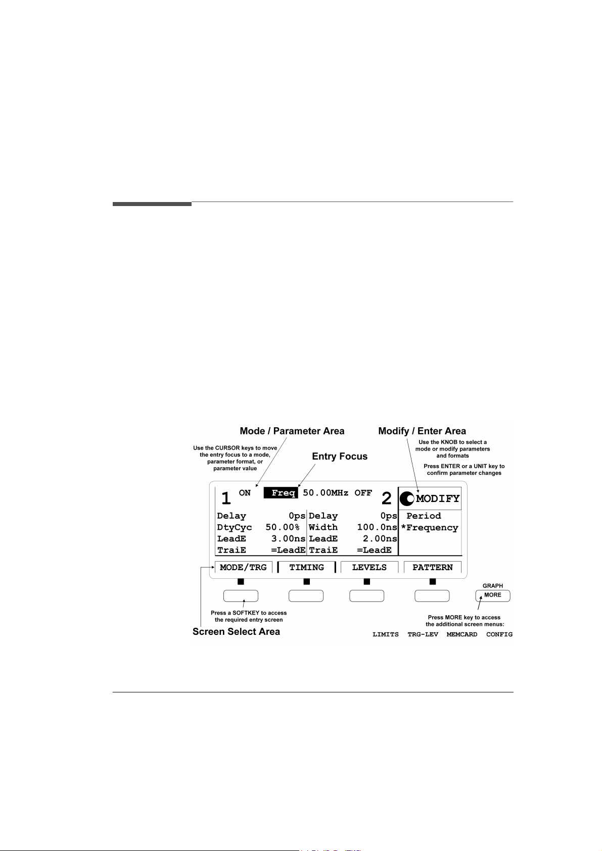
Figure 7 Display and Softkey Front Panel Section
|P ATTERN| screen.
The display contains three different areas, Mode / Parameter, Modify /
Enter and Screen Selection areas.
HP 81110/04 A Quick Start Introduction 37

Introduction
User Interface Concept
The Controls
Movement of the entry focus within the Mode & Parameter section of
the display is controlled by the Cursor Keys.
Figure 8 Front Panel Controls
Numerical Data Entry
Numerical data is entered by the Data Entry keys and va lidated ei ther by
a Unit key or the key.
Parameter Selection and Modification
The Modify knob can be used in the Modify area of the display. Modes
can be selected and changed in th e Modify Area or paramet er values can
38 Introduction HP 81110/04A Quick St art

Introduction
User Interface Concept
be varied to display an immediate change at the output.
When is displayed, select a mode , a p ara me te r f or mat or modify the parameter value and validate the value with a unit key.
When is displayed, make the s elect ion an d press the
key to start a function.
HP 81110/04 A Quick Start Introduction 39

Introduction
Quick Access of Menus and Parameters
Quick Access of Menus and Parameters
Additional Func ti ons
Most keys of the front panel have an additional function. The
key provides fast access to ad dit io nal func ti ons of the Data
Entry keys and the Special Function keys.
For example, it is possible to quickly access the pulse width parameter
of output 2 by pressing , the instrument then
asks for the channel, so press (if two channels are installed).
The entry field is positioned on the output 2 width parameter editing
field.
Select Step Size
The + or + moves the cur-
sor to a different digit in the MODIFY area, so it is possible to change
step size for parameter change, then vary the value either with the up/
down cursor keys or the knob.
40 Introduction HP 81110/04A Quick St art

Introduction
Quick Access of Menus and Parameters
Overprogramming
With + it is possible to exceed specified parame-
ter ranges to utilize the instrument to its limits.
NOTE: Proper operation of the instrument outside of the specified ranges
is not guaranteed. It i s reco mmended to ha ve the o utpu ts swit ched
on when overprogramming, t o have the i nternal e rror chec k sytem
activated, which warnsyou about impossible settings.
Display Modes
In the following figure the results of pressing a sof tke y a re dis pl ayed. In
this case it is possible to toggle between textual and graphical screens.
The toggle mode is available for the
TERN|
softkeys. It is possible to alternate between a textual display and
waveform display by pressing the softkey as required.
|TIMING|, |LEVELS| and |PAT-
Figure 9 Toggling Display Mode
HP 81110/04 A Quick Start Introduction 41
Introduction
Quick Access of Menus and Parameters
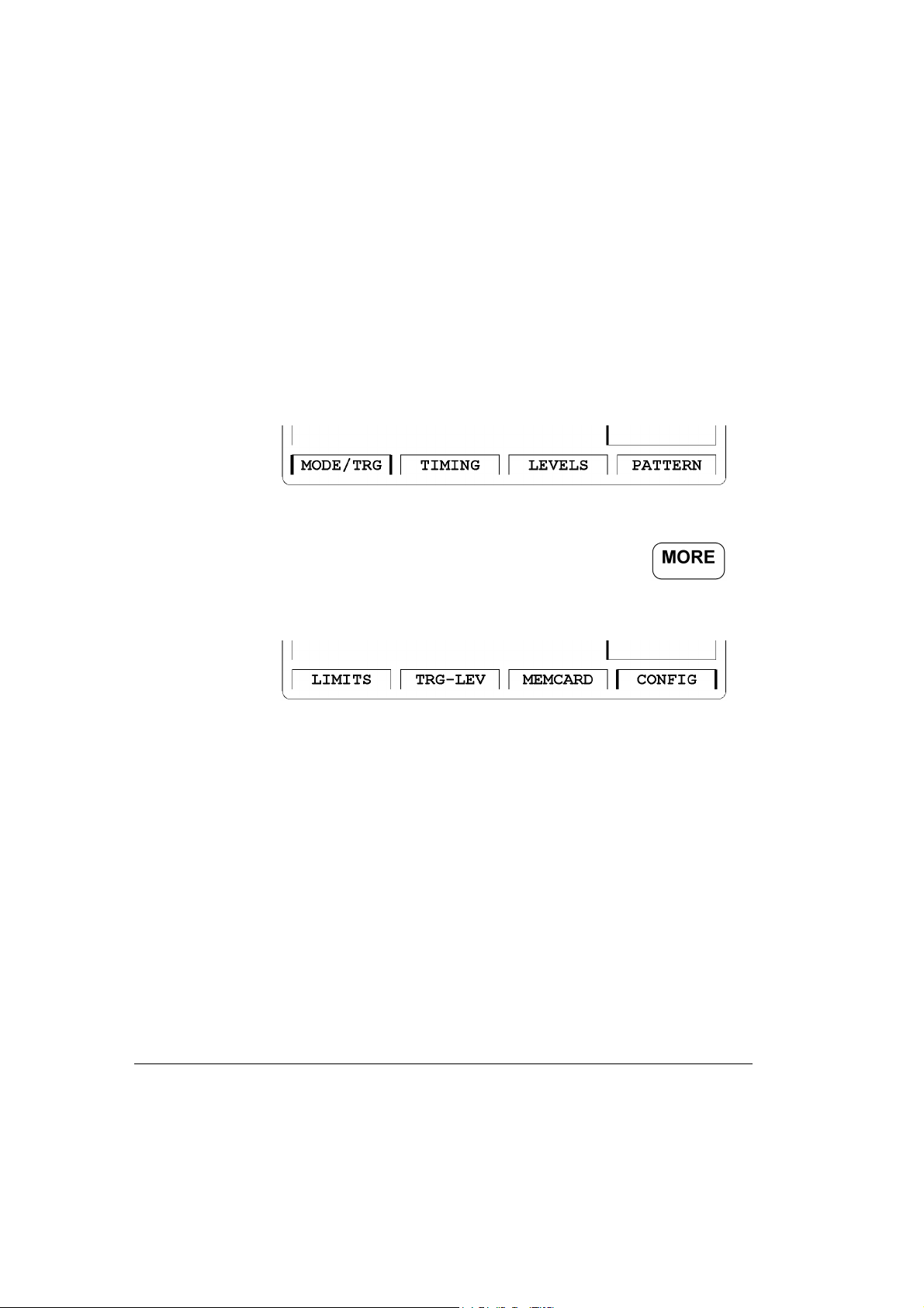
Screen Menus
The Softkeys allow access to the screen menus and can toggle betwee n
screens where applicable.
Figure 10 Screen Menus of a dual channel instrument
Additional screen menus can be accessed by pressing the
softkey leading to the following screen selection area.
Figure 11 Additional Screen Menus
42 Introduction HP 81110/04A Quick St art

Introduction
Special Function Keys
Special Function Keys
Shift/Local Function Key
The key provides fast access to additional functions.
The key can be used when, in remote control, the front
panel controls are locked. Press the key to unlock the front panel controls.
Help Function Key
The key provides access to the instru ments on-li ne help or in
Warning or Error state, access to Warning/Error Report Screen.
Store/Recall Function Key
The key can be used to store/recall from 1 to 9 individual
settings in th e instrument memory.
HP 81110/04 A Quick Start Introduction 43

Introduction
Special Function Keys
Default Setting
In the interna l memory locati on 0 there is a de fault setting stored, press
the keys to reset the instrument to
the default setting.
Manual Trigger Function Key
The key can be used in triggered or gated mode to manually
trigger the in strument if there is no other source available.
44 Introduction HP 81110/04A Quick St art

Introduction
Screens Overview
Screens Overview
The instrument is designed to create pulse streams, burst signals and
data streams, ther efore the instr ument has to be s et to the oper ating mode
required, to set the operating mode please refer to “Available Operating/
Trigger Modes” on page 47.
The instrument can be t riggere d, gated or used as a pulse si gnal reco very
instrument (external width), to set the trigger mode refer also to “Avail able Operating/Trigger Modes” on page 47.
NOTE: Triggered or gated mode is available only when int ernal Oscillator
is used as period generation source.
The instrument can be equipped with one or two output channels. It is
possible to independently program the timing and level parameters of
both channels.
If two channels are installed it is possible to select either the parameter
grouping for
for
|OUTPUT 1| and |OUTPUT 2|.
To change grouping of the parameter r ef er t o “Chang ing Conf iguration”
on page 62.
|TIMING| and |LEVELS| or all timing and level parameters
Most parameters can be entered in 2 or more different formats, e.g.
width or duty cycle or trailing delay. To select the parameter format and
to set the parameters, refer to “Setting Timing Parameter Fo rmats and
Values” on page 49.
Entering pattern for a data stream can be done in the pattern screen, refer
to “Editing Pattern” on page 54.
To protect voltage sensitive DUTs the instrument has the output voltage
limitation feature . For how to se t limits ref er to “Sett ing Limits” on pa ge
57.
HP 81110/04 A Quick Start Introduction 45

Introduction
Screens Overview
The instrument can se t thresholds and the input impedance for an external trigger signal or external high-stability clock input. For the trigger
output, available in pulse mode and the strobe output, available in burst
and pattern mode, it is possible to select between TTL or ECL output
levels. For how to set thresholds or trigger levels refer to “Thresholds
and Trigger-Levels” on page 59.
The instrument allows to read and store instrument settings from and to
a memory card. The reading and storing is done in the
|MEMCARD| menu, refer to “Reading/ Storing on Memory Card” on
page 60.
46 Introduction HP 81110/04A Quick St art

Introduction
Av ailable Operating/Trigger Modes
Available Operating/Trigger Modes
Figure 12 MODE/TRG Screen
Access the Operating/Trigger Mode (MODE/TRG) screen by pressing
the
|MODE/TRG| softkey. Move the Entry Focus with the cursor keys.
In this screen you set the fundamental operating and trigger modes with
respect to the signal required. For example, the operating mode for a
simple clock or pulse signal is the pulse stream (
Pulse Strm), PULSES
mode. Burst signals (several pulses and a pause) are easily set up in
BURST mode. Data streams (also PRBS’s) require the Pattern mode.
You can specify the pulse period source. If you have to trigger after an
external event then use the starta ble osci llator (internal Osc) which st arts
on the external signal with a fixed latency. If you do not have to trigger
but need a high accuracy freq uency, then use the interna l PLL cloc k generation circuitry. In triggered/gated mode the internal PLL can be used
as trigger sou rce.
In
Pattern mode you specify the data outp ut format in this screen, either
RZ or NRZ.
The available selecti ons are :
HP 81110/04 A Quick Start Introduction 47

Introduction
Available Operating/Trigger Modes
1 Trigger Mode - CONTINUOUS, TRIGGERED, GATED,
EXT. WIDTH
2 Operat ing Mode -
PULSES, BURST of, PATTERN of
3 Pulse Type - Single-Pulses, Double-Pulses
4 Number of Bursts - 2 to 65536
5 Data Output Format - RZ, NRZ
Can also be varied in the |PATTERN| screen.
6 Pulse Period Source -
internal Osc, internal PLL, CLK-IN
7 Trigger/Gate Sour ce - EXT INPUT, PLL, MAN KEY
8 Trig ger/Gate Even t - Rising, Falling, Both / HighLev el, LowLevel,
Always
Trigger and Strobe Output
The Trigger Output is always available and marks each pulse period
with a 50% duty cycle signal. In Ext Width the trigger output width is
5.9 ns for the HP 81104A, and 1.5 ns for the HP 81110A.
Additionally, in burst mode the Strobe output is available. The Strobe
output rises at the start of the first pulse-period and falls at the start of
the last pul se-period.
Additionally, in pattern mode the Strobe output is available. The Strobe
output is bit-programmable with NRZ data output format.
Table 2: Trigger and Strobe Output Availability
Pulse Mode Burst Mode Pattern Mode
Continuous
Triggered T T, S T, S
Gated T T, S T, S
Ext. Width Tn/an/a
1
T = Trigger Out
2
S = Strobe Out
48 Introduction HP 81110/04A Quick St art
1
T
T, S
2
T, S

Introduction
Setting Timing Parameter Formats and Values
Setting Timing Parameter Formats and
Values
Figure 13 TIMING Screen
Access the timing entry (TIMING) menu screen by pressing the
|TIMING| softkey.
In this screen you can set the timing parameters individually for both
channels. This is except for period/frequency, which defines the system
clock rate for both channels.
All parameters can be entered in different parameter formats, please
select from:
1 The System Clock Mode -
2 Delay Parameter -
3 Width Parameter - Width, DutyCycle, Trail Del
4 Leading Edge Parameter - Absolute,% of Wid
HP 81110/04 A Quick Start Introduction 49
Absolute, % of Per, Phase
Period, Frequency.

Introduction
Setting Timing Parameter Formats and Values
NOTE: For HP 81110A with HP 81112A, 3.8V/330 MHz Output channels
installed you can select between two fixed transitions, 800 ps or
1.6 ns. The trailing edge is always the same as the leading edge.
5 Trailing Edge Parameter - =
Lead E, Absolute,% of Width
6 Output Status - ON, OFF
Can also be varied in the |LEVELS| screen.
NOTE: If only one channel is installed, then all signal parameters are
grouped in an OUTPUT screen. If yo u prefe r the si gnal pa ramete r
grouping for each Output, then please refer to “Changing
Configuration” on page 62. Refer also to “Output/Output 1 and
Output 2 Parameter Grouping” on page 64.
7 Differential Output Status -
ON, OFF
Can also be varied in the |LEVELS| screen.
NOTE: Differential Outputs are available with HP 81110A with
HP 81112A, 3.8V/330 MHz Output channels installed.
Switch the output status to ON to avoid para meter conflicts, please refer
to “Internal Error Check” on page 52.
50 Introduction HP 81110/04A Quick St art

Introduction
Setting Level Parameter Formats and Values
Setting Level Parameter Formats and
Values
Figure 14 LEVELS Screen
Access the level entry (LEVELS) menu screen by pressing the
|LEVELS| softkey.
In this screen you can set the level values individually for both channels.
As with the TIMING screen you can enable or disable the outputs. All
parameters can be entered in different parameter formats, e.g. it is possible to enter the levels as current values by changing the unit to ampere.
Please select from:
1 Channel OUTPUT Status -
Can also be varied in the |TIMING| screen.
2 Differential Output Status -
Can also be varied in the |TIMING| screen.
NOTE: Differential Outputs are available with HP 81110A with
HP 81112A, 3.8V/330 MHz Output channels installed.
3 OUTPUT Mode -
HP 81110/04 A Quick Start Introduction 51
Normal, Complmnt
ON, OFF
ON, OFF

Introduction
Setting Level Parameter Formats and Values
4 Channel Output Option - Separate Outputs, Added at Output1
NOTE: Channel addition (Added at Output1) is available with HP 81104A
and HP 81110A with HP 81111A, 10V/165 MHz Output channels
installed.
5 Fixed Levels Formats -
Set TTL, Set ECL
6 Variable Level Formats - High-Low, Off-Ampl
7 Unit Format - in volt, in ampere
8 Source Impedance Values - 50 Ω ,
1
ΚΩ
NOTE: Selectable source impedance and variable load impedance is
available with HP 81104A and HP 81110A with HP 81111A,
10V/165 MHz Output channels installed.
9 Load Im pedance Values -
0.1 Ω − 1 ΜΩ
NOTE: If only one channel is installed, then all signal parameters are
grouped in an OUTPUT screen. If yo u prefe r the si gnal pa ramete r
grouping for each Output, then please refer to “Changing
Configuration” on page 62.
Internal Error Check
When the output status is in OFF pos ition the internal error check is
switched off and it is possible to set each parameter to any valid value.
So, it is possible to program even conflicting values between
parameters. When switching the outputs ON the instrument will
immediately show a flashing W. Pressing the Help key will list all
parameter conflicts.
Recommendation:
To avoid long lists of warnings it is recommended to:
a Check and set the output levels in the |LEVELS| screen to a va lue
52 Introduction HP 81110/04A Quick St art

Introduction
Setting Level Parameter Formats and Values
which does not damage your DUT.
b Switch the ou tput status to ON to get imm ediately res ponse if y ou try to pro -
gram a conflicting parameter combination in |LEVELS| or |TIMING|
screen.
HP 81110/04 A Quick Start Introduction 53

Introduction
Editing Pattern
Editing Pattern
Figure 15 PATTERN Screen
Shows which memory location
can actually be edited
Bit-editing Window
Set the pattern length here
NOTE: Make sure that in the |M ODE/TRG| screen the pattern operating mo de
is selected. Please refer to “A vailable Operating/T rigger Modes” on page
47.
Access the pattern entry (PATTERN) menu screen by pressing the
|PATTERN| softkey. This screen has to be accessed for pattern entry
when data streams in Patt ern operating mode will be set up.
NOTE: A signal with a number of pulses followed by a pause is what we
would call a burst signal. Such burst signals are recommended to
be set up in the burst mode, as this is done more quic kly and easier
as it would be in the pattern mode.
54 Introduction HP 81110/04A Quick St art

Introduction
Editing Pattern
In pattern mode the Str obe output has add itional up to 1638 4 bit memory
depth with NRZ data output always. So, the Strobe output is the comfortable trigger output in patte rn mode.
In this screen you can select:
1 Update Status -
Upd Once, Update Cont
If the changes of pattern should immediately affect the output select
Upd Cont.
If you want to set up new pattern while a data stream is currently
generated select
Upd Once. Edit your new pattern, then press the
key to make the new pattern active on the output.
2 Current memory location - Addr - shows the current position of the
bit-editing window.
Move the entry field to the bit-editing window and enter the pattern.
The bit-editing window aut omatically moves one location to the right.
The bit-editing window can be moved across the pattern length by
varying the
Addr. Either change the Addr with the kn ob or by typing
in a new address with the Data Entry keys.
The range is
1-length of pattern (max 16384).
3 Length of pattern - Last - shows the last address and is equal to the
length of the data stream.
Set the required pattern length by specifying the
range is
2-16384.
Last address. The
4 Block Editing Functions for - CH1, CH2, BOTH, STRB
It is possible to manipulate each Ou tput channel sep arately
or together,
BOTH. The strobe output STRB is available and can be
CH1, CH2
programmed individually . There are block editin g functions available
to fill memory with 0 or1, to i nvert the pattern, to set a PRBS or filling
HP 81110/04 A Quick Start Introduction 55

Introduction
Editing Pattern
the memory with a divided clock pattern.- Fill 0, Fill 1, Invert,
First Bit, Last Bit, Ins Bit, Del Bit, Clock÷N, PRBS 2n-1.
NOTE: Most of the block editing functions apply from (or at) the current Addr
of the bit-editing window to the Last bit in the pattern
For further information on the block editing functions, please refer to the
HP 81110A / HP 81104A Reference Guide (p/n 81110-91010 ) Chapt er 1,
Pattern Screen.
5 Data Output Format - RZ, NRZ
Can also be varied in the |MODE/TRG| screen.
56 Introduction HP 81110/04A Quick St art
Introduction
Setting Limits
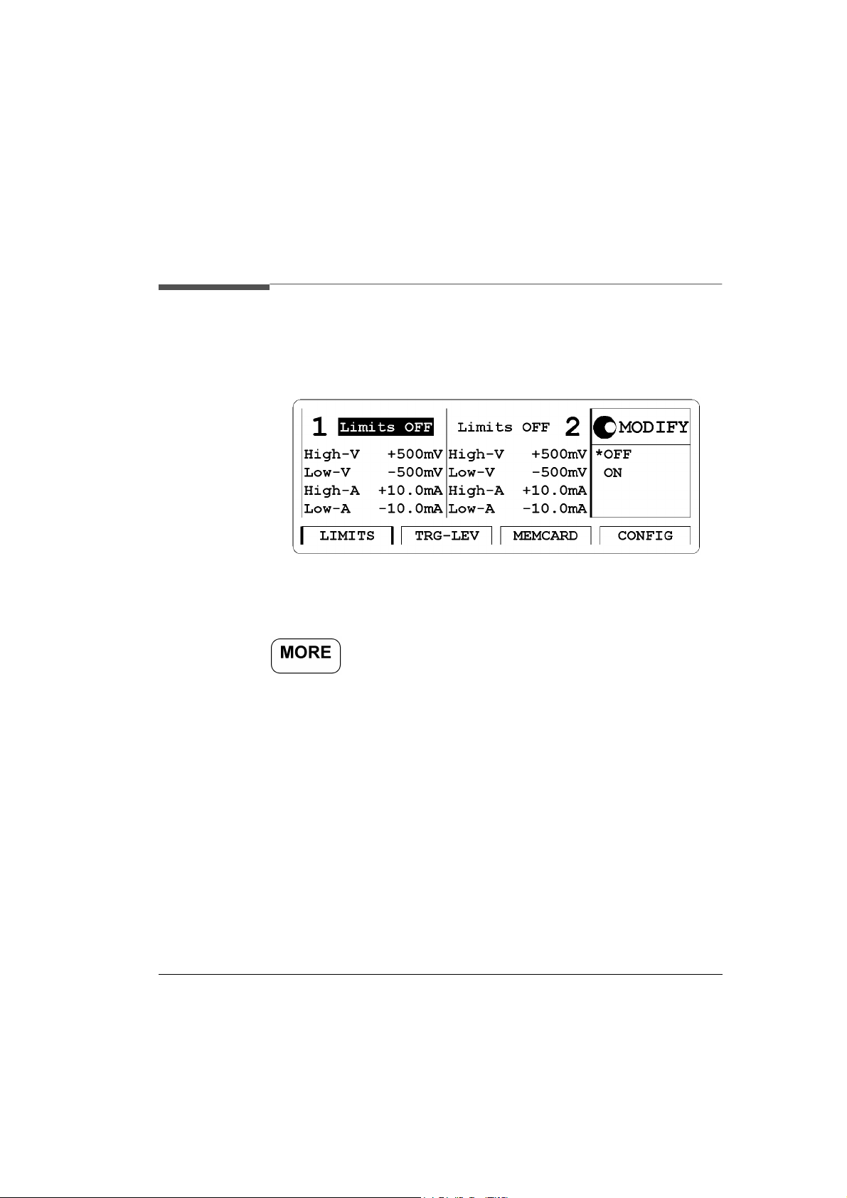
Setting Limits
Figure 16 LIMITS Screen
Access the output limitation (LIMITS) menu screen by pressing the
softkey then pressing the
|LIMITS| softkey.
To prevent your device from being damaged by excess ive voltages it is
recommended to limit the output of the instrument. You can switch the
limit feature on, or off and set the required limits as either voltages or
currents.
Please select from:
1 Limits Status -
ON, OFF
2 High Voltage Limit - High-V
For the 10 V output channels HP 81105A and HP 81111A the range
-19.8V to +20.0V
is:
For the 3.8 V output channels HP 81112A the range is: -1.90V to
+3.80V
HP 81110/04 A Quick Start Introduction 57

Introduction
Setting Limits
3 Low Voltage Limit - Low-V
For the 10 V output channels HP 81105A and HP 81111A the range
is:
-20V to +19.8V
For the 3.8 V output channels HP 81112A the range is: -2.00V to
+3.70V
4 High Curr ent Limit - High-A
For the 10 V output channels HP 81105A and HP 81111A the range
is:
-792 mA to +800 mA
For the 3.8 V output channels HP 81112A the range is: -76.0 mA to
+152 mA
5 Low Current Limit - Low-A
For the 10 V output channels HP 81105A and HP 81111A the range
is:
-800 mA to +792 mA
For the 3.8 V output channels HP 81112A the range is: -80.0 mA to
+148 mA
58 Introduction HP 81110/04A Quick St art

Introduction
Thresholds and Trigger-Levels
Thresholds and Trigger-Levels
Figure 17 TRG-LEV Screen
Access the trigger le vel (TRG-LEV) menu screen by pressing the
softkey then pressing the
In this screen you can set the thresholds for external and clock reference
signals and the input impedanc e. For th e output tri gger and strobe signa l
specify the output levels, either TTL or ECL.
The available selecti ons are :
1 EXT-IN -
Voltage Range - -10V to +10 V
Input Resistance - 10kΩ Inp or 50Ω Inp
2 CLK-IN -
Voltage Range - -10V to +10V
Input Resistance - -10kΩ Inp or 50Ω Inp
3 Trigger-Out - TTL, ECL
4 Strobe -Out- TTL, ECL
HP 81110/04 A Quick Start Introduction 59
Set TTL, Set ECL, Voltage
Set TTL, Set ECL, Voltage
|TRG-LEV| softkey.

Introduction
Reading/Storing on Memory Card
Reading/Storing on Memory Card
Figure 18 MEMCARD Screen
Access the memory card (MEMCARD) menu screen by pressing
the softkey then pressing the |MEMCARD| softkey.
The main operations on the MEMCARD screen are:
• Store instrument settings to the memory-card
• Recall instrument settings from the memory-card
• Delete files from the memory-card
• Format the memory-card
If a memory card is plugged in the memory card slot on the front panel
you can select:
1 Dir Path- displayed if there is a plugged in memory card with a
directory created on a DOS PC.
2Filename- list of the filenames which are present on the plugged in
memory card.
3 Perform Operation -
Format
60 Introduction HP 81110/04A Quick St art
ReadCard, Recall, Store, Store All, Delete,

Introduction
Reading/Storing on Memory Card
NOTE: the HP 81110A or HP 81104A support only DOS formatted
memory-cards and you cannot create or delete directories using
the HP 81110A or HP 81104A.
The HP 81110A and HP 81104A support memory cards up to
2 MB, SRAM Type.
The filenames can be up to 8 characters long.
HP 81110/04 A Quick Start Introduction 61

Introduction
Changing Configuration
Changing Configuration
Figure 19 CONFIG Screen
NOTE: Timing Calibration is available with the HP 81110A only.
Access the Configuration (CONFIG) menu screen by pressing the
softkey then pressing the
In this screen you can vary the HP-IB address when the instrument is
used in remote control operation The factory set HP-IB address is 10. It
is possible to invoke a selftest.
With the HP 81110A the ti ming self calibration feature can be started in
this window - Perform: Timing Calibration. Apart from the factory
calibration of the instruments, the timing self calibration allows to
calibrate the instrument in respect to the actual ambient temperature.
When the HP 81110A is switched off and on again, the factory
calibration data are va lid again.
You can select the parameter grouping from either TIMING and
LEVELS or OUTPUT 1 and OUTPUT 2. You can also define what the
62 Introduction HP 81110/04A Quick St art
|CONFIG| softkey.

Introduction
Changing Configur ati on
PLL reference source is, eit her the internal on-board refer ence or a much
more stable external reference.
Please select from:
1 HP-IB Addr ess Range -
1 to 30
2 Perform Option- Selftest, Timing Calibration (HP 81110A only)
3 Group Parameters by - TIMING/LEVELS, OUTPUT 1/2
4 PLL Refe re nce Sour ce - Internal, CLK-IN: Freq 5 MHz or 10 MHz
HP 81110/04 A Quick Start Introduction 63
Introduction
Output/Output 1 and Output 2 Parameter Grouping
Output/Output 1 and Output 2
Parameter Grouping
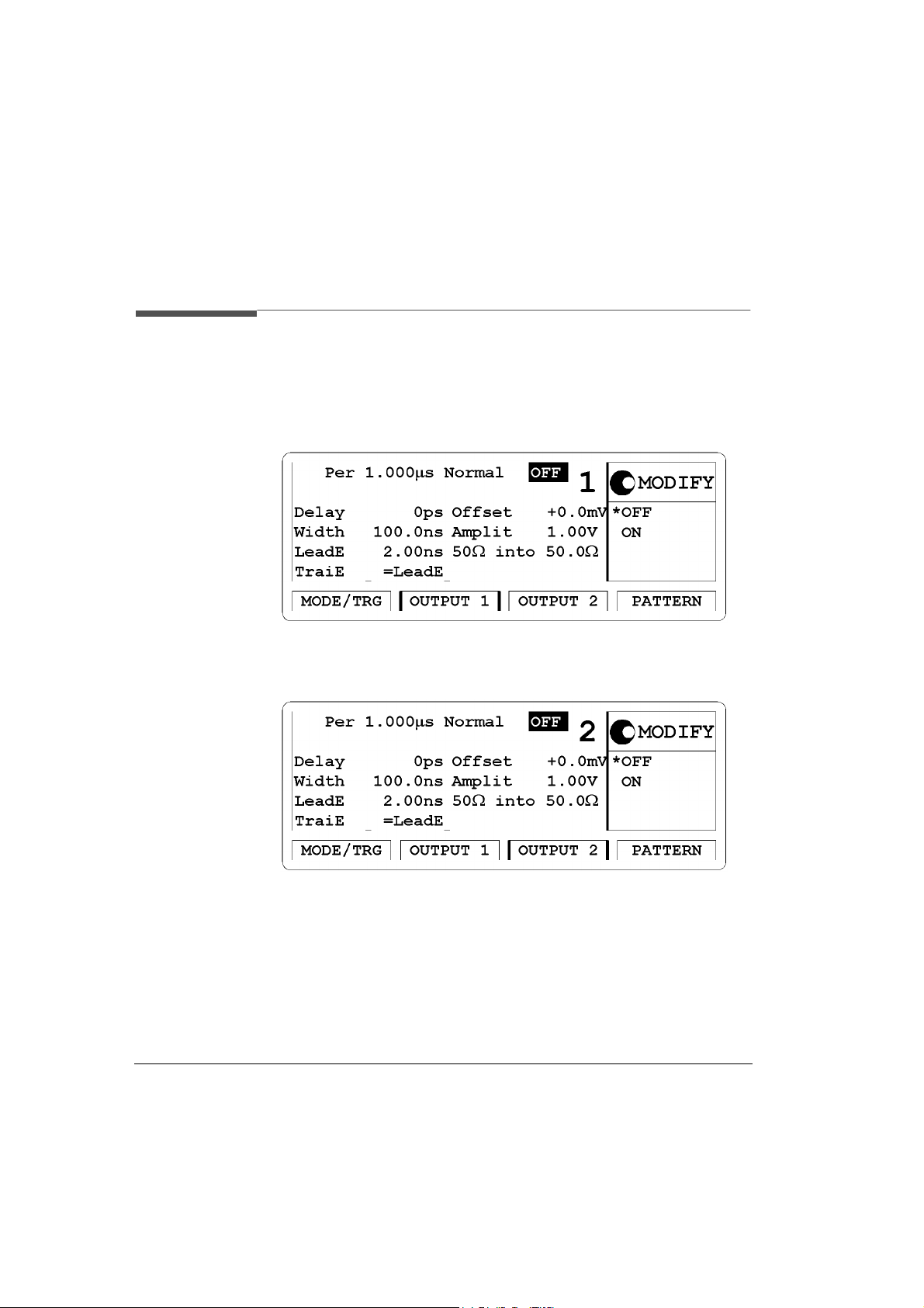
Figure 20 OUTPUT 1 Screen of a dual channel instrument
Figure 21 OUTPUT 2 Screen
64 Introduction HP 81110/04A Quick St art

Introduction
Output/Output 1 and Output 2 Parameter Grouping
Figure 22 Output Screen of a single channel instrument
The |OUTPUT| screen is standard for a single channel instrument. The
|OUTPUT 1| and |OUTPUT 2| timing and level grouping is configurable
for dual channel instruments.
After selecting
Group Params by: OUTPUT 1/2 in the |CONFIG| screen,
see “Changing Configura tion” on pa ge 62, the 2 Output Sof tkey options
are available. The timing and level parameters are grouped together for
each output.With the exception of period/frequency all parameters can
be individually set for each output.
All parameters can be entered in different formats. For the available
parameter and format selections, please refer to “Setting Timing
Parameter Formats and Values” on page 49. Refer also to “Setting
Level Parameter Formats and Values” on page 51.
HP 81110/04 A Quick Start Introduction 65
Introduction
An Overview of the Front and Rear Panel
An Overview of the Front and Rear Panel
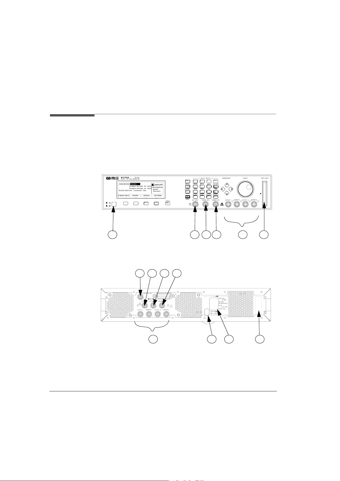
Figure 23 Front Panel View
1
Figure 24 Rear Panel View with Option UN2
5
6
2
3
4
4
5
3
8
2
9
7
10
The numbers in the Figures correspond to the numbers in the following
list.
66 Introduction HP 81110/04A Quick St art

Introduction
An Overview of the Front and Rear Panel
Inputs and Outputs
1 Standby Switch
NOTE: When the front panel switch is off, the Mainframe is in ’Standby’
mode. Disconnection from the AC Line Power is accomplished
only by disconnecting the power cord.
2 OUTPUT 1/2 - Signal outputs, channel 2 optional.
OUTPUT 1/2
with HP 81112A 3.8V/330 MHz Output channels installed.
3 TRIGGER OUT
A signal with risin g edge ma rking the st art of each pu lse- period . For
further informati on r ef er to “Trigger and Strobe Output” on page 48.
4 STROBE OUT
• The Strobe output rises at the start of the first pulse-period and falls
at the start of the last pulse-per iod mar kin g start a nd e nd of th e burst
in Burst mode.
• Bitwise programmable in Pattern mode. NRZ data format.
• Not used in Pulses mode.
• For further information refer to “Trigger and Strobe Output” on
page 48.
5 EXT INPUT - Connect an external t rigger or gate si gnal here, or use
EXT -WIDTH mode to perform pulse recovery.
NOTE: When rear panel option UN2 is ordered the connectors 2), 3), 4)
and 5) are at the rear panel.
6 PLL REF IN/CLK IN - Connect an exter nal fr equency re fere nce or
clock signal here, if a higher frequency accuracy than 0.01% is
required, or if you need fr equency locking.
- Differential signal outputs available with HP 81110A
7 Memory Card slot
HP 81110/04 A Quick Start Introduction 67

Introduction
An Overview of the Front and Rear Panel
8 Fuse Holder
9 AC Line Socket
10 Serial Number Label
68 Introduction HP 81110/04A Quick St art

Chapter 3
3Getting Started
HP 81110/04A Quick Start Getting Started 69

Getting Started
Introduction
Introduction
The intention of this chapter is to give the necessary steps to set up
generic signals for fi rst time users of the HP 81110A or HP 81104A.
Additionally, advanced signals are also described step by step to enable
even experienced users to set up signals more quickly.
When using this product for the first time it is recommended t o read
Chapter 2, Introduction to get familiar with the user Interf ace concept
and the fundam entals of puls e parameters, fo r User Interface Concept
description see page 37 .
Manual Example Signals
Generic Signals
1 How to set up a Clock Signal (see page 72 )
2 How to set up a Pulse Signal (see page 79 )
3 How to set up a Serial Data Stream Signal (see page 86 )
Advanced Signals
4 How to set up an Edge-displacement Signal (see page 91 )
5 How to set up a Dual Clock Signal (see page 97 )
6 How to set up Burst Signals (see page 103 )
Programming Examples
At the end of each manual example signal, the required set of device
commands are listed. For further information of the commands and a
complete command reference see Chapter 2 of the Reference Guide, p/n
81110-91011.
70 Getting Started HP 81110/04A Quick Start

Getting Started
Introduction
Documentation Conventions:
|TIMING| Press the |TIMING| softkey to access the
TIMING parameter screen.
Entry Focus The highlight field, can be moved with the
cursor keys, to either change a mode or
parameter.
24 ns Enter this value and unit with the DATA
ENTRY keys
Freq Select the mode or parameter name with
the knob.
Keys to press in the DATA ENTRY area
on the front panel.
MODIFY \
CURSOR > Use the front panel controls.
DATA ENTRY /
:VOLTage:HIGH 3V Full command for pattern, 3V high level.
The upper case letters represent the short
form of the command, which results in
faster programming times.
*RST Common IEE 488 command, to reset
instrument to d efault status
:DISPlay OFF Switch off the au tomatic update of the
display, when instrument is used in remote
control operations. This increases the
programming speed.
HP 81110/04A Quick Start Getting Started 71
Getting Started
Examples
Examples
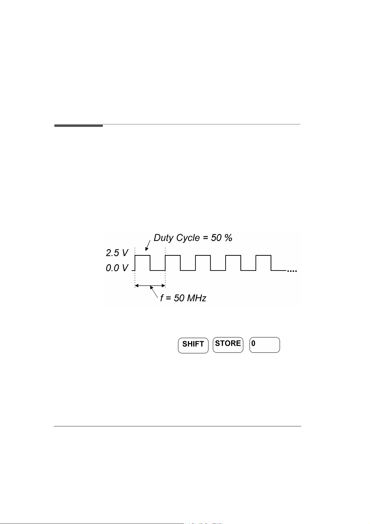
1. Setting up a C l ock Signal
Here, a continuous clock signal with 50 MHz frequency with PLL accuracy, a duty cycle of 50%, 3 ns tr ansition times , a h igh l evel of 2.5 V and
low level of 0 V, will be set up.
Figure 25 Clock Signal Diagram
1 Before setting up the signal it is recommended to reset all parameters
and modes by pressing .
72 Getting Started HP 81110/04A Quick Start
Getting Started
Examples
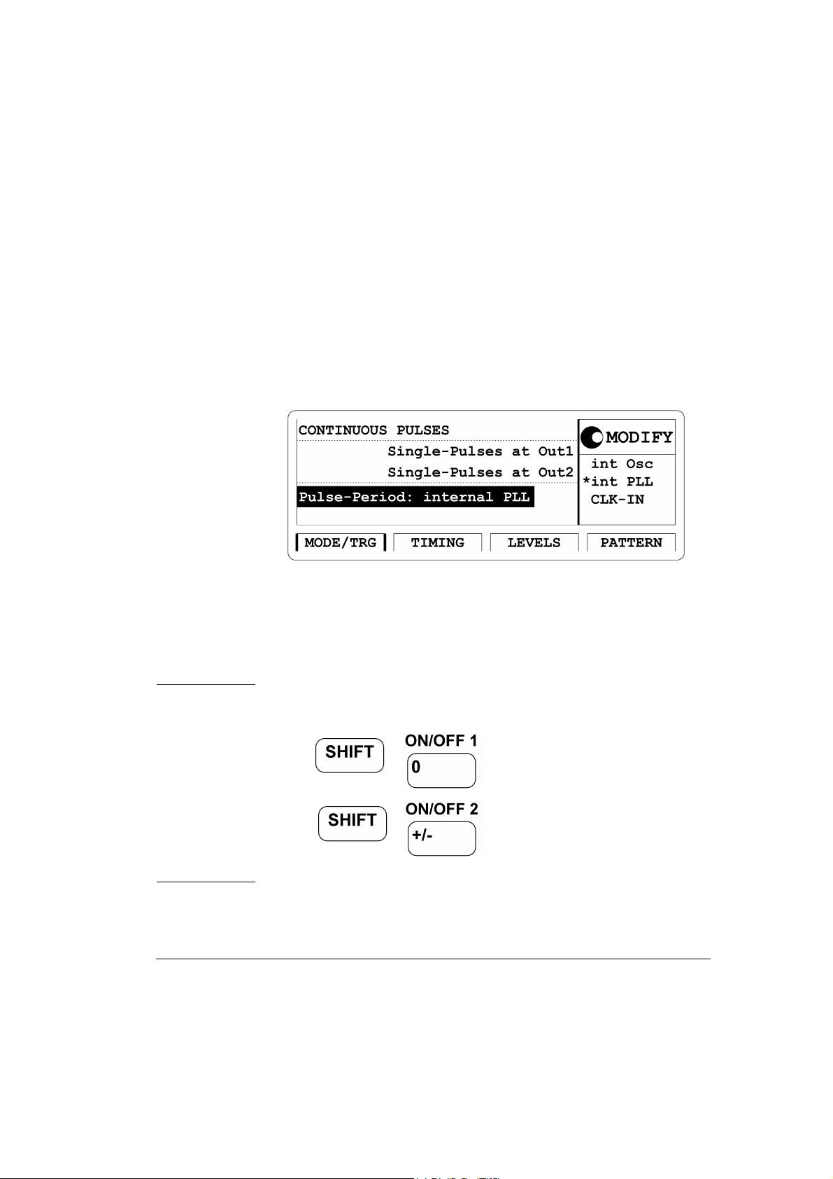
2 Press the |MODE/TRG| softkey to enter the Operatin g/Trigger Mode
menu. Use the cursor keys to move the Entry Focus to the Trigger
mode
CONTINUOUS. Move the Entry Focus to the right and select
PULSES. Move the Entry Focus down to select Single-Pulses at Out1
and then
Figure 26 Current MODE/TRG Screen
Pulse-Period: internal PLL.
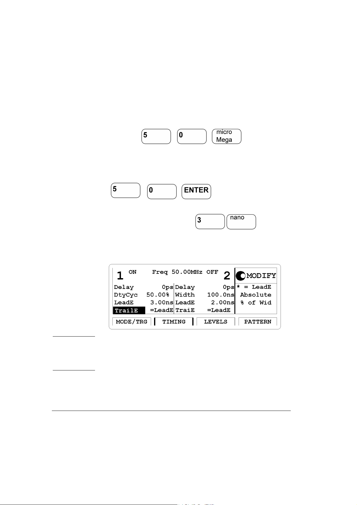
3 Press the |TIMING| softkey to enter the Timing menu.
• Move the Entry Focus to the Output 1 status with the cursor keys.
ON in the Modify area to turn on the Output 1.
Select
NOTE: The Output channel can be turned on and off in either the
|LEVELS| or |TIMING| screens or by the following: pressing
for Output 1 and
for Output 2. Repeated pressing of
the keys toggles the output state from on to off and vise versa.
• Move the Entry Focus to
HP 81110/04A Quick Start Getting Started 73
Per and select Freq.
Getting Started
Examples
• Move the Entry Focus to Freq ent ry field and e nter a valu e of 50 MHz
by pressing
• Move the Entry Focus down to the width of Output 1 and select
tyCyc
.
Du-
Move Entry Focus to the right and enter 50% by typing
• Move Entry Focus down to enter for the leading edge. Trailing edge should be the sa me as leading ed ge. (
Lead E
Figure 27 Current TIMING Screen
)
Trail E =
NOTE: With HP 81110A with HP 81112A 3.8V/330 MHz Output
channels installed the transition times can be either 800 ps or 1.6
ns, trailing edge is equal to leading edge. The minimum transition
times for the HP 81104A are 3 ns.
74 Getting Started HP 81110/04A Quick Start
4 Press the |LEVELS| softkey to enter the Levels menu.
Getting Started
Examples
• Move the Entry Focus to
IFY area
High-Low, then move Entry Focus to high level entry field
Offset and Amplitude and select in the MOD-
and press for
high level and move down the Entry Focu s to the low level entry field
and press .
Figure 28 Current LEVELS Screen for HP 81104A and HP 81110A
with HP 81111A installed
Figure 29 Current LEVELS Screen for HP 81110A with HP 81112A in-
stalled
HP 81110/04A Quick Start Getting Started 75

Getting Started
Examples
5 Here is the signal as displayed on an HP 54810A Infinium
oscilloscope. Use the generator’s TRIGGER OUT to trigger the
scope.
Figure 30 Resulting Signal
76 Getting Started HP 81110/04A Quick Start

Getting Started
Examples
Device Command List for the Clock Signal
• If you want to include this Clock Signal in your program use the
following command lines in boldface font. The comment lines starting with a # are not required.
• The commands are listed with the channel specifier for channel 1, if
there is a second channel install ed and you want to program it with a
similar signal, use the same commands and replace 1 by 2 for the
second channel, where required.
# Reset the instrument to start from a defined, default status.
*RST
# Switch off the automatic display update to increase programming
# speed.
:DISPlay OFF
# Internal PLL has to be set as period source.
:ARM:SOURce INT2
# Set the frequency to 50 MHz, the duty cycle to 50% and the leading
# and trailing edge to 3 ns. Settings are to program for output 1.
:FREQuency 50MHZ
:PULSe:DCYCle1 50
:PULSe:TRANsition1 3NS
# For example, the same settings for the optional second channel will
# look like as follow s:
:PULSe:DCYCle2 50
HP 81110/04A Quick Start Getting Started 77

Getting Started
Examples
:PULSe:TRANsition2 3NS
# Set the high level to 2.5 Volts, the low level to 0.0 Volts.
:VOLTage1:HIGH 2.5V
:VOLTage1:LOW 0V
# Enable the output 1 and the complement output 1 (HP 81110A
# with HP 81112A 3.8V/330 M Hz output channel installed, only).
:OUTPut1 ON
:OUTPut1:COMPlement ON
78 Getting Started HP 81110/04A Quick Start

Getting Started
Examples
2. Setting up a Pulse Signal
Here a continuous pul se si gnal wi th 20 ns p eriod , a pul se widt h of 1 0 ns,
a leading edge of 3 ns, a tr ai ling edge of 5 ns, an amplitude of 3.3 V and
an offset of 1.65 V (high level 3.3 V, low level 0.0 V) will be set up.
Figure 31 Pulse Signal Diagram
1 Before setting up the signal it is recommended to reset all parameters
and modes by pressing .
HP 81110/04A Quick Start Getting Started 79

Getting Started
Examples
2 For reference the current |MODE/TRG| screen is displayed.There is
nothing to change.
Figure 32 Current MODE/TRG Menu
3 Press the |TIMING| softkey to enter the Timing menu.
•Switch
• Enter a period of
ON the Output Channel 1.
20 ns. Enter a pulse width of 10 ns.
•Enter 3 ns for leading edge. Se lect Absolute for trailing edge and enter
a value of
5 ns.
NOTE: With HP 81110A with HP 81112A 3.8V/330 MHz Output
channels installed the transition times can be either 800 ps or 1.6
ns, trailing edge is equal to leading edge. The minimum transition
times for the HP 81104A are 3 ns.
80 Getting Started HP 81110/04A Quick Start

Getting Started
Figure 33 Current TIMING Screen
NOTE: The Output channel can be turned on and off in either the
|LEVELS| or |TIMING| screens or by the following: pressing
for Output 1 and
Examples
for Output 2. Repeated pressing of
the keys toggles the output state from on to off and vise versa.
HP 81110/04A Quick Start Getting Started 81

Getting Started
Examples
4 Press the |LEVELS| softkey to enter the Levels menu.
Enter an offset of 1.65 V and an amplitude of 3.30 V.
Figure 34 Current LEVELS Screen for HP 81104A and HP 81110A
with HP 81111A installed
Figure 35 Current LEVELS Screen for HP 81110A with HP 81112A in-
stalled
82 Getting Started HP 81110/04A Quick Start
Getting Started
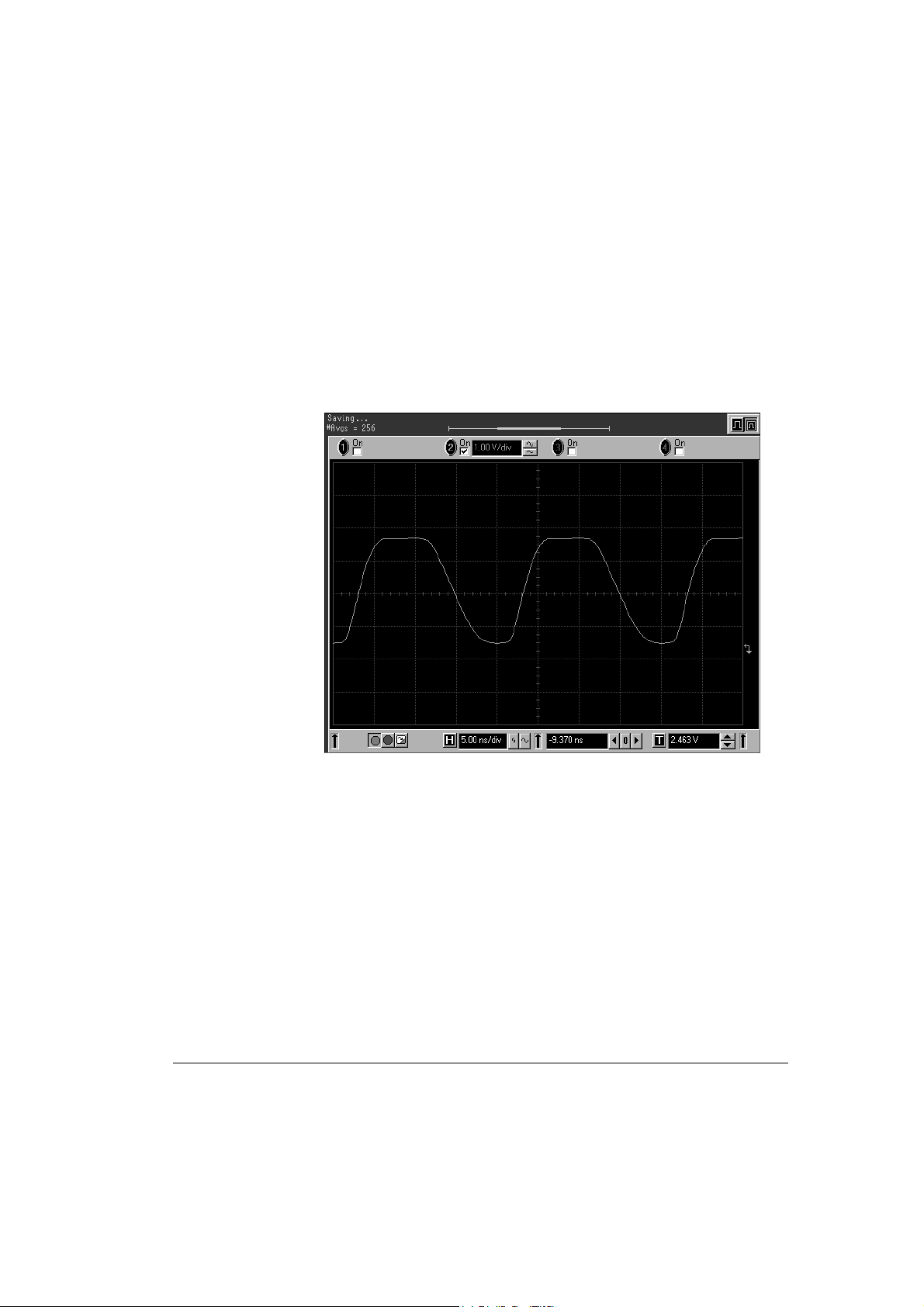
5 Here is the figure as displayed on the HP 54810A Infinium
oscilloscope. Use the generator’s TRIGGER OUT to trigger the
scope.
Figure 36 Resulting Display
Examples
HP 81110/04A Quick Start Getting Started 83

Getting Started
Examples
Device Command List for the Pulse Signal
• If you want to include this Pulse Signal in your program use the fol-
lowing command lines in boldface font. The comment lines starting
with a # are not required.
• The commands are listed with the channel specifier for channel 1, if
there is a second channel install ed and you want to program it with a
similar signal, use the same commands and replace 1 by 2 for the
second channel, where required.
# Reset the instrument to start from a defined, default status.
*RST
# Switch off the automatic display update to increase programming
# speed.
:DISPlay OFF
# Pulse stream operating mode is required, but as we start from a
# default status it is not necessary to send a command for setting the
# instrument into pulse stream operating mode.
# Set the period to 20 ns, the pulse width to 10 ns, the leading edge to
# 3 ns and the trailing edge to 5 ns.
:PULSe:PERiod 20NS
:PULSe:WIDTh1 10NS
:PULSe:TRANsition1 3NS
:PULSe:TRANsition1:TRAiling:AUTO OFF
:PULSe:TRANsition1:TRAiling 5NS
84 Getting Started HP 81110/04A Quick Start

Getting Started
Examples
NOTE: For HP 81110A with HP 81112A 3.8V/330 MHz Output channel
installed the transitions can be selected either 800 ps or 1.6 ns.
Leading and trailing edge are equal.
# Set the amplitude to 3.3 Volts, the offset to 1.65 Volts.
:VOLTage1 3.3V
:VOLTage1:OFFSet 1.65V
# Enable the output 1 and the complement output 1 (HP 81110A
# with HP 81112A 3.8V/330 M Hz output channel installed, only).
:OUTPut1 ON
:OUTPut1:COMPlement ON
HP 81110/04A Quick Start Getting Started 85

Getting Started
Examples
3. Setting Up a Serial Data Stream Signal
Here a continuous 24 bit long pattern signal with NRZ data output format at 80 MBit/s and ECL output level will be set up. The pattern is
‘111001110011001001010010’.
1 Before setting up the signal it is recommended to reset all parameters
by pressing .
2 Press the
menu. Select
Out 1
Figure 37 Current MODE/TRG Screen
|MODE/TRG| softkey to enter the Operating/Trigger Mode
CONTINUOUS PATTERN of. Highlight RZ- Pulses at
and select NRZ.
86 Getting Started HP 81110/04A Quick Start

Getting Started
Examples
3 Press the |TIMING| softkey to enter the Timing menu. Switch ON the
Output 1.
Enter frequency of 80 MHz.
NOTE: It is recommended to set the width for channel 2 to 6.250 ns to
avoid a parameter conflict when switching on this channel.
The
‘-------’ in the output 1 width ent ry field relate to the NRZ dat a
output format selection.
Figure 38 Current TIMING Screen (for HP 81110A)
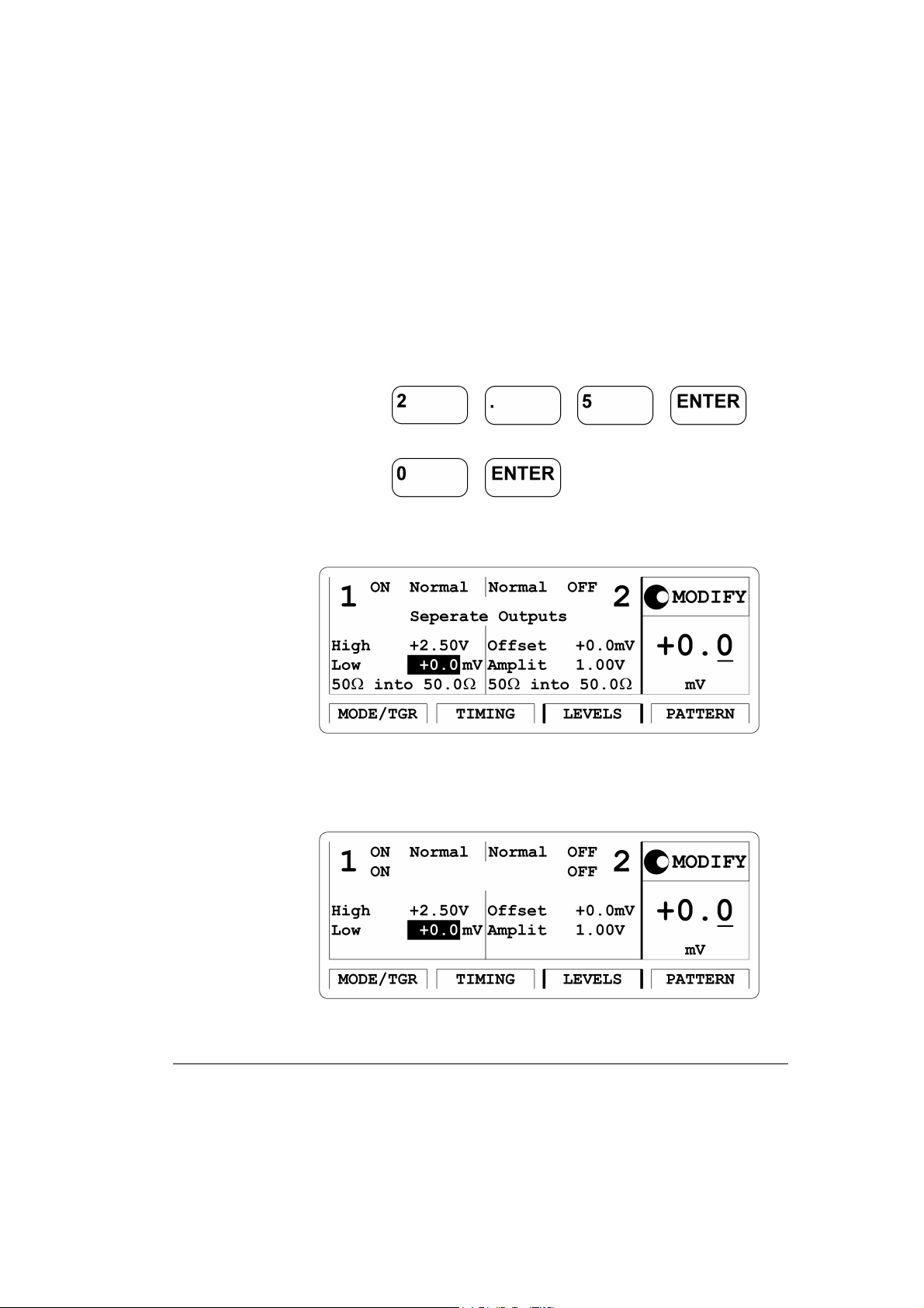
4 Press the |LEVELS| softkey to enter the Levels menu. Change Offset
and
Amplitude mode to ECL levels by selecting Set ECL in the
Modify Area.
Figure 39 Current LEVELS Screen
NOTE: HP 81110A with HP 81112A 3.8V/330 MHz Output channels
installed have fixed 50
Ω source impedance and does not offer to
adjust for a load impedance different then 50 Ω.
HP 81110/04A Quick Start Getting Started 87
Getting Started
Examples
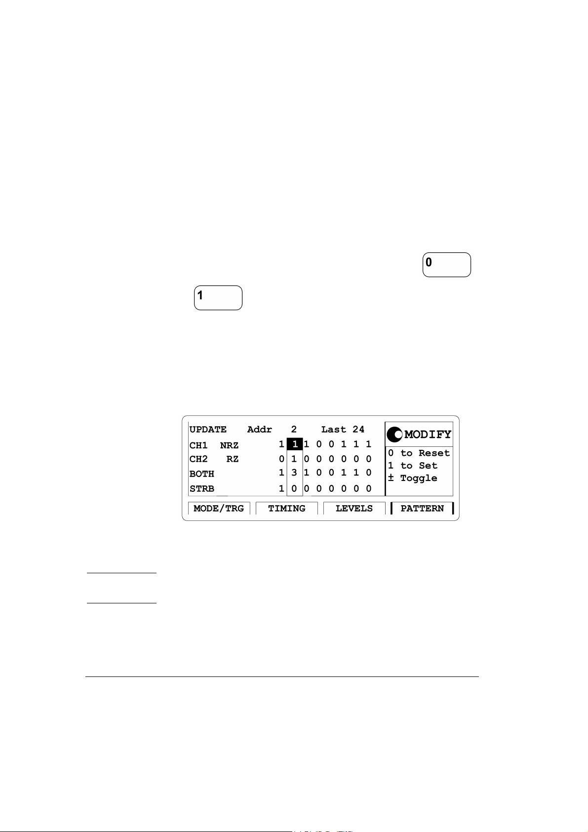
5 Press the |PATTERN| softkey to enter the Pattern menu.
• Move the Entry Field to
Last and input a value of 24.
• Move the Entry Fie ld to the b it-editing wi ndow for CH1 and enter the
pattern ‘111001110011001001010010’ by pressing th e
or key, respecively. When entering the pattern the bitediting window moves automatically one location to the right. By
turning the knob c ount er cl ockwise you can move th e bi t -editing window back. The actual memory location on which the the bit-editing
window is pointing is shown by Addr.
Figure 40 Current PATTERN Screen
NOTE: To get a stable displa y of th e pattern str eam on a n os cill oscope set
1 bit of the Strobe (STRB) and trigger the scope.
88 Getting Started HP 81110/04A Quick Start

Getting Started
Examples
Device Command List for the Data Stream Signal
• If you want to include this Data Stream Signal in your program use
the following command lines in boldface font. The comment lines
starting with a # are not required.
• The commands are listed with the channel specifier for channel 1, if
there is a second channel install ed and you want to program it with a
similar signal, use the same commands and replace 1 by 2 for the
second channel, where required.
# Reset the instrument to start from a defined, default status.
*RST
# Switch off the automatic display update to increase programming
# speed.
:DISPlay OFF
# Set the instrument to pattern mode and select NRZ data output format
# for output 1.
:DIGital:PATTern ON
:DIGital:SIG Nal1:FORMat NRZ
# For example the command to set NRZ data fo rmat for the optional
# second channel is:
# :DIGital:SIGNal2:FORMat NRZ
# Define a pattern length of 24 bit and program the pattern:
# ‘111001110011001 00101 0010’.
:TRIGger:COUNt 24
HP 81110/04A Quick Start Getting Started 89

Getting Started
Examples
:DIGital:PATTern:DATA1 #224111001110011001001010010
# Set the frequency to 80 MHz, and output 2 width to 6.25 ns to avoid a
# parameter conflict.
:FREQuency 80MHZ
:PULSe:WIDTh2 6.25NS
# Set the output voltage to fixed ECL levels.
:VOLTage1:HIGH -0.85V
:VOLTage1:LOW -1.8V
# Enable the output 1 and the complement output 1 (HP 81110A
# with HP 81112A 3.8V/330 M Hz output channel installed, only).
:OUTPut1 ON
:OUTPut1:COMPlement ON
90 Getting Started HP 81110/04A Quick Start
Getting Started
Examples
4. Setting Up an Edge-displacement Signal
NOTE: Two Outputs are required for this example. The channel addition
feature is used for this example. Therefore, this type of signal can
be performed by HP 81104A and HP 81110A with HP 81111A
10V/165 MHz Outputs.
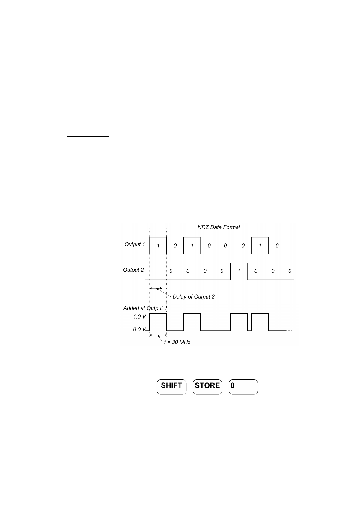
Here a continuous pattern signal, with one distorted pulse will be set up.
The two channels are added with NRZ (Non Return to Zero) pulses at
both outputs, high level of 1 V and low level of 0 V and Channel 2 delay
of 10 ns. The bit frequency is 30 MHz.
Figure 41 Edge-displacement Signal Diagram
1 Before setting up the signal it is recommended to reset all parameters
by pressing .
HP 81110/04A Quick Start Getting Started 91

Getting Started
Examples
2 Press the |MODE/TRG| softkey to enter the Operating/Trigger Mode
Menu. Select
1 and
NRZ-Pulses at Out 2 using the MODIFY knob.
Figure 42 Current MODE/TRG Screen
CONTINUOUS PATTERN of. Select NRZ-Pulses at Out
3 Pres s the |PATTERN| softkey t o enter t he Patter n menu. Set up the bit
pattern as follows. Enter 8 for Last.
Move to bit-editing window for CH 1 and enter pattern
10100010 for
channel 1. Move down to CH2 and select firs t addres s by turning the
know counterclockwise and enter pattern
00001000 for channel 2.
Figure 43 Current PATTERN Screen
92 Getting Started HP 81110/04A Quick Start
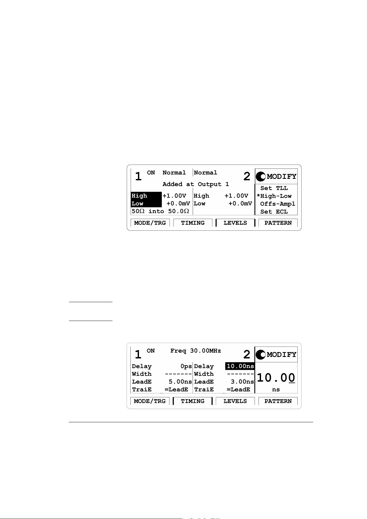
Getting Started
Examples
4 Pres s the |LEVELS| so ftkey to enter the Leve ls menu. Switch ON both
channels. Change
level to
Figure 44 Current LEVELS Screen
1.00 V and low level to 0.0 mV for both outputs.
Separate Outputs to Added at Output 1. Set high
5 Press the |TIMING| softkey to en ter the Timing me nu. Enter a
frequency of
30 MHz and a delay of 10 ns for Output 2. Vary output 2
delay to displace the pulse as required.
Output 2 has additional 2.5 ns del ay in channel addition mod e. Als o,
the typical tranisiton times are 5 ns. So, enter transistions of 5 ns for
Output 1 to ac hieve same t ransition time shape in the added signal.
NOTE: The ‘-------’ in the width entry fields relate to the NRZ data output
format selection.
Figure 45 Current TIMING Screen
HP 81110/04A Quick Start Getting Started 93

Getting Started
Examples
6 Here is the HP 54810A Infinium Scope display of the distorted and
displaced pulse generated by the instrument. Use the generator’s
STROBE OUT to trigger the scope.
Figure 46 Resulting Signal
94 Getting Started HP 81110/04A Quick Start

Getting Started
Examples
Device Command List for the Edge-displacement
Signal
• If you want to include this Edge-displacement Signal in your program use the following command lines in boldface font. The comment lines starting with a # are not required.
NOTE: Two Outputs are required for this example. As channel addition
feature is used this t ype of signal can be pe rformed by HP 81104A
and HP 81110A with HP 81111A 10V/165 M Hz Outputs.
# Reset the instrument to start from a defined, default status.
*RST
# Switch off the automatic display update to increase programming
# speed.
:DISPlay OFF
# Set the instrument to pattern mode and select NRZ data output format
# for output 1 and output 2.
:DIGital:PATTern ON
:DIGital:SIG Nal1:FORMat NRZ
:DIGital:SIG Nal2:FORMat NRZ
# Define a pattern length of 8 bit and program for channel 1 the pattern
# 10100010, for the channel 2 the pattern 00001000, see manual step 3.
:TRIGger:COUNt 8
:DIGital:PATTern:DATA1 #1810100010
HP 81110/04A Quick Start Getting Started 95

Getting Started
Examples
:DIGital:PATTern:DATA2 #1800001000
# Set the frequency to 30 MHz, and a delay of 10 ns for output 2, the
# transition times for output 1 to 5ns to have same transition time
# shape as the added second channel, see comment in step 5.
:FREQuency 30MHZ
:PULSe:TRANsition1 5NS
:PULSe:DELay2 10NS
# Set the output voltage to high level 1.0 Volts and low level to 0.0 Volts
# for both channels. Then select channel addition mode, see manual
# step 4.
:VOLTage1:HIGH 1V
:VOLTage1:LOW 0V
:VOLTage2:HIGH 1V
:VOLTage2:LOW 0V
:CHANnel:MATH PLUS
# Enable the output 1 and the output 2.
:OUTPut1 ON
:OUTPut2 ON
96 Getting Started HP 81110/04A Quick Start

5. Setting Up a Dual Clock Signals
NOTE: For this example two Outputs are required.
Here a Dual Clock Signal will be set up. In pattern mode with NRZ
(Non Return to Zero) pulses, a period of 12.5 ns and a high level of
2.50 V and a low of 0 V. Output 1 generates a clock signal tha t i s h alf of
the system clock. Output 2 divides the system clock by 8.
Figure 47 Dual Clock Signal Diagram
Getting Started
Examples
NOTE: With an additional dual channel instrument, multiples of these
dual clock signals can be set up following a similar procedure as
follows. For example, wit h 8 dua l c h ann el unit s up to 16 different
clocks can be generated.
1 Before setting up the signal it is recommended to reset all parameters
by pressing .
HP 81110/04A Quick Start Getting Started 97

Getting Started
Examples
2 Press |MODE/TRG| softkey to enter Operating/Trigger mode menu.
Select
Pattern of with NRZ-PULSES at OU T 1 & OUT 2.
Figure 48 Current MODE/TRG Screen
3 Press the |PATTERN| softkey to enter the Pattern menu. Enter 8 for
Last. Move to CH1 and select Clock÷N, press ENTER key twice to
get a pattern for clock division by 2. Move to CH2 and select
Clock÷N, press ENTER ke y. Press 8 and ENTER k ey, to get a patt ern
for clock division by 8.
Figure 49 Current PATTERN Screen
98 Getting Started HP 81110/04A Quick Start

Getting Started
Examples
4 Press the |TIMING| softkey to enter the Timing menu. Switch ON
both outputs.
Figure 50 Current TIMING Screen
Set the per iod to 12.5 ns.
5 Go to the |LEVELS| Menu to set the a ppropriate clock output voltages.
Set high levels of
Figure 51 Current LEVELS Screen
2.50 V and low levels of 0.0 mV for both outputs.
NOTE: The TIMING and LEVELS screens for HP 81110A with
HP 81112A 3.8V/330 MHz Outputs look different to the screens
shown here as this instrument has no channel addition, fixed
source impedance of 50
Ω, assumes 50 Ω load impeda nce a nd has
differential outputs .
HP 81110/04A Quick Start Getting Started 99
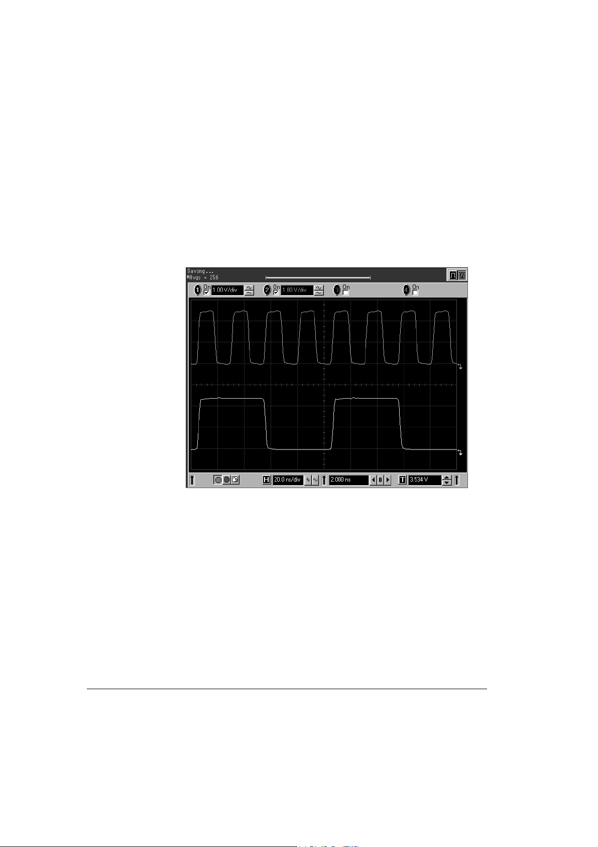
Getting Started
Examples
6 Here is the HP 54810A Infinium Scope Display of the two different
frequency clock signals generated by the instrument Use the
generator’ s STROBE OU T to trigger th e scope.
Figure 52 Resulting Signals
100 Getting Started HP 81110/04A Quick Start

Device Command L i st for the Dual Clock Signal
• If you want to include this Dual Clock Signal in your program use
the following command lines in boldface font. The comment lines
starting with a # are not required.
NOTE: A second channel is required.
# Reset the instrument to start from a defined, default status.
*RST
# Switch off the automatic display update to increase programming
# speed.
:DISPlay OFF
# Set the instrument to pattern mode and select NRZ data output format
# for output 1 and output 2.
Getting Started
Examples
:DIGital:PATTern ON
:DIGital:SIGNa1l:FORMat NRZ
:DIGital:SIG Nal2:FORMat NRZ
# Define a pattern length of 8 bit and program for channel 1 a pattern
# with clock division by 2, for channel 2 a pattern with clock division
# by 8.
:TRIGger:COUNt 8
:DIGital:PATTern:PRESet1 2,8
:DIGital:PATTern:PRESet2 8,8
HP 81110/04A Quick Start G etting Started 101

Getting Started
Examples
# Set the period to 12.5 ns.
:PULSe:PERiod 12.5NS
# Set the output voltage to high level 2.5 Volts and low level to 0.0 Volts
# for both channels.
:VOLTage1:HIGH 2.5V
:VOLTage1:LOW 0V
:VOLTage2:HIGH 2.5V
:VOLTage2:LOW 0V
# Enable the output 1 and the output 2.
:OUTPut1 ON
:OUTPut2 ON
# To enable the complement output 1 and the complement output 2
# (only HP 81110A with HP 81112A 10V/330 MHz outputs installed)
# the following commands have to be included:
:OUTPut1:COMPlement ON
:OUTPut2:COMPlement ON
102 Getting Started HP 81110/04A Quick Start
 Loading...