

Page 1

Agilent 75000 Series C
Agilent E1465A/E14 66A/E1467 A
Relay Matr ix Swit ch Mo dule s
User’s Manual and SCPI Programming Guide
Where to Find It - Online and Printed Information:
If your instrument has a Agilent VXIplug&play driver,
product information is organized as indicated below.
System installation (hardware/software)............. VXIbus Configuration Guide*
Agilent VIC (VXI installation software)*
Module conf i gur at i on and wiring........................ This Manual
SCPI programming.............................................. This Manual
SCPI example programs...................................... This Manual
SCPI command reference ................................... This Manual
Register-based programming .............................. This Manual
VXIplug&play programming ............................. VXIplug&play Online Help
VXIplug&play example programs. ..................... VXIplug&play Online Help
VXIplug&play function referenc e ...................... VXIplug&play Online Help
Soft Front Panel information............................... VXIplug&play Online Help
VISA language information........... ..................... Agilent VISA User’s Guide
Agilent VEE programming information ............. Agilent VEE User’s Manual
*Supplied with Agile nt Command Modules,Embedded Controll e rs, and V X Link.
*E1466-90006*
Manual Part Number: E1466-90006
Printed in Malaysia E0406
Page 2

Page 3

Contents
Agilent E1465/66/67A Relay Matrix Switch Modules
Warranty . . . . . . . . . . . . . . . . . . . . . . . . . . . . . . . . . . . . . . . . . . 5
Safety Symbols . . . . . . . . . . . . . . . . . . . . . . . . . . . . . . . . . . . . . . 6
WARNINGS . . . . . . . . . . . . . . . . . . . . . . . . . . . . . . . . . . . . . . . . 6
Declaration of Conformity . . . . . . . . . . . . . . . . . . . . . . . . . . . . . . . . . 7
User Notes . . . . . . . . . . . . . . . . . . . . . . . . . . . . . . . . . . . . . . . . . 8
Chapter 1. Getting Started . . . . . . . . . . . . . . . . . . . . . . . . . . . . . . . . . . . . 11
Using This Chapter . . . . . . . . . . . . . . . . . . . . . . . . . . . . . . . . . . . . 11
Matrix Description . . . . . . . . . . . . . . . . . . . . . . . . . . . . . . . . . . . . . 11
Instrument Definition . . . . . . . . . . . . . . . . . . . . . . . . . . . . . . . . . . . 15
Programming the Matrix . . . . . . . . . . . . . . . . . . . . . . . . . . . . . . . . . . 15
Specifying SCPI Commands . . . . . . . . . . . . . . . . . . . . . . . . . . . . . . 15
Initial Operation . . . . . . . . . . . . . . . . . . . . . . . . . . . . . . . . . . . . . . 18
Chapter 2. Configuring the Matrix Modules . . . . . . . . . . . . . . . . . . . . . . . . . . . 21
Using This Chapter . . . . . . . . . . . . . . . . . . . . . . . . . . . . . . . . . . . . 21
WARNINGS and CAUTIONS . . . . . . . . . . . . . . . . . . . . . . . . . . . . . . 21
Setting the Module Address Swi tch . . . . . . . . . . . . . . . . . . . . . . . . . . . . 22
Selecting the Interrupt Line . . . . . . . . . . . . . . . . . . . . . . . . . . . . . . . . 23
Installing the Relay Matrix Switch Module in a Mainframe . . . . . . . . . . . . . . . 24
Wiring the Standard Terminal Module . . . . . . . . . . . . . . . . . . . . . . . . . . 25
Attaching the S tandard Termin al M odul e to th e Re l ay Matrix Switch Mod ule . . . . . 27
Connector Pin-Out . . . . . . . . . . . . . . . . . . . . . . . . . . . . . . . . . . . . . 28
The Agilent E 1465A Terminal M odul e . . . . . . . . . . . . . . . . . . . . . . . . . . 29
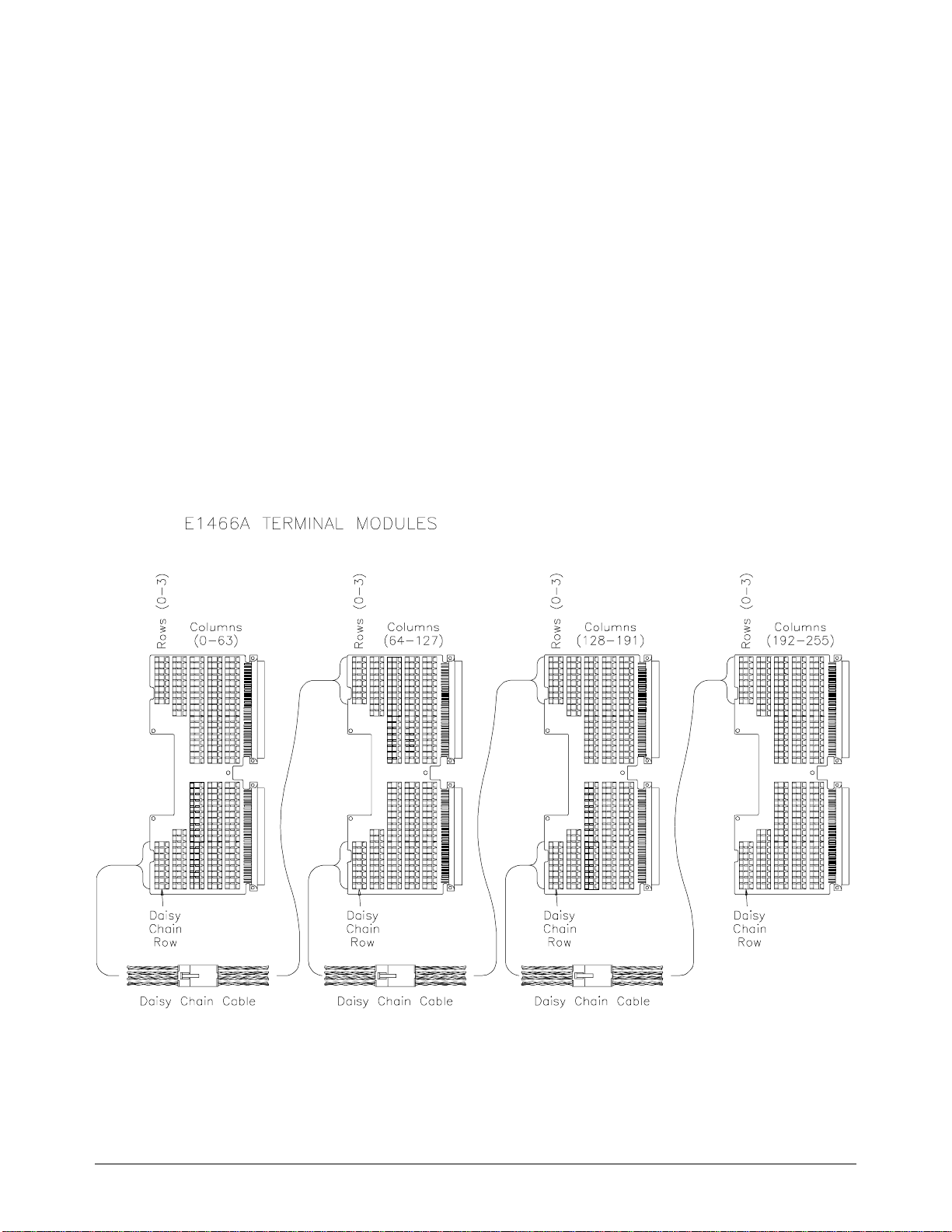
The Agilent E 1466A Terminal M odul e . . . . . . . . . . . . . . . . . . . . . . . . . . 30
The Agilent E 1467A Standard Terminal Modul e . . . . . . . . . . . . . . . . . . . . . 31
Creating Larger Matrices with Agilent E1465/66/67A Modules . . . . . . . . . . . . . 32
Module Configuration . . . . . . . . . . . . . . . . . . . . . . . . . . . . . . . . . 32
Module Address . . . . . . . . . . . . . . . . . . . . . . . . . . . . . . . . . . . . 32
Agilent E1467A Option 211 Matrix Expansion Terminal Module . . . . . . . . . . . 36
Option 211 Expansion Terminal Module Front Panel . . . . . . . . . . . . . . . . . 37
Attaching the E1 467A O pt io n 211 M a trix Expansion T er minal Module . . . . . . . . . 38
Attaching Cables . . . . . . . . . . . . . . . . . . . . . . . . . . . . . . . . . . . . 40
Using Multiple Mainframes . . . . . . . . . . . . . . . . . . . . . . . . . . . . . . . . 41
Chapter 3. Using the Matrix . . . . . . . . . . . . . . . . . . . . . . . . . . . . . . . . . . . 43
Using This Chapter . . . . . . . . . . . . . . . . . . . . . . . . . . . . . . . . . . . . 43
Matrix Commands . . . . . . . . . . . . . . . . . . . . . . . . . . . . . . . . . . . . . 43
Power-On and Reset Conditions . . . . . . . . . . . . . . . . . . . . . . . . . . . . . 44
Module Identification . . . . . . . . . . . . . . . . . . . . . . . . . . . . . . . . . . . 44
Switching Channels . . . . . . . . . . . . . . . . . . . . . . . . . . . . . . . . . . . . 46
Example: Sequencing Through the Agilent E1466A Channels . . . . . . . . . . . . 47
Scanning Channels . . . . . . . . . . . . . . . . . . . . . . . . . . . . . . . . . . . . . 47
Example: Scanning Channels with System Multimeter Using TTL Trigger . . . . . 48
Example: Scanning Channels with an External Instrument
Using Trigger In and Out . . . . . . . . . . . . . . . . . . . . . . . . . . . . . . . 49
Agilent E1465/66/67A Relay Matrix Switch Modules Contents 1
Page 4

Querying the Matrix Module . . . . . . . . . . . . . . . . . . . . . . . . . . . . . . . 51
Using the Scan Complete Bit . . . . . . . . . . . . . . . . . . . . . . . . . . . . . . . 52
Recalling and Saving States . . . . . . . . . . . . . . . . . . . . . . . . . . . . . . . . 53
Detecting E rror Conditions . . . . . . . . . . . . . . . . . . . . . . . . . . . . . . . . 54
Synchronizing the Matrix Module . . . . . . . . . . . . . . . . . . . . . . . . . . . . . 56
Understanding the Relay Matrix . . . . . . . . . . . . . . . . . . . . . . . . . . . . . . 57
Advantages of Latching Relays . . . . . . . . . . . . . . . . . . . . . . . . . . . . 57
Increased Sy ste m T hroughput . . . . . . . . . . . . . . . . . . . . . . . . . . . . . 57
Chapter 4. Relay Matrix Command Reference . . . . . . . . . . . . . . . . . . . . . . . . . 59
Using This Chapter . . . . . . . . . . . . . . . . . . . . . . . . . . . . . . . . . . . . 59
Command Types . . . . . . . . . . . . . . . . . . . . . . . . . . . . . . . . . . . . . . 59
Common Command Format . . . . . . . . . . . . . . . . . . . . . . . . . . . . . . 59
SCPI Command Format . . . . . . . . . . . . . . . . . . . . . . . . . . . . . . . . . . 60
Command Separator . . . . . . . . . . . . . . . . . . . . . . . . . . . . . . . . . . 60
Abbreviated Commands . . . . . . . . . . . . . . . . . . . . . . . . . . . . . . . . 60
Implied Commands . . . . . . . . . . . . . . . . . . . . . . . . . . . . . . . . . . . 61
Parameters . . . . . . . . . . . . . . . . . . . . . . . . . . . . . . . . . . . . . . . 61
Linking Commands . . . . . . . . . . . . . . . . . . . . . . . . . . . . . . . . . . 62
SCPI Command Reference . . . . . . . . . . . . . . . . . . . . . . . . . . . . . . . . 63
ABORt . . . . . . . . . . . . . . . . . . . . . . . . . . . . . . . . . . . . . . . . . . . 63
ARM . . . . . . . . . . . . . . . . . . . . . . . . . . . . . . . . . . . . . . . . . . . . 64
:COUNt . . . . . . . . . . . . . . . . . . . . . . . . . . . . . . . . . . . . . . . . . 64
:COUNt? . . . . . . . . . . . . . . . . . . . . . . . . . . . . . . . . . . . . . . . . 65
DISPlay . . . . . . . . . . . . . . . . . . . . . . . . . . . . . . . . . . . . . . . . . . 66
:MONitor[:STATe] . . . . . . . . . . . . . . . . . . . . . . . . . . . . . . . . . . . 66
:MONitor:CARD . . . . . . . . . . . . . . . . . . . . . . . . . . . . . . . . . . . . 67
INITiate . . . . . . . . . . . . . . . . . . . . . . . . . . . . . . . . . . . . . . . . . . 68
:CONTinuous . . . . . . . . . . . . . . . . . . . . . . . . . . . . . . . . . . . . . . 68
:CONTinuous? . . . . . . . . . . . . . . . . . . . . . . . . . . . . . . . . . . . . . 69
[:IMMediate] . . . . . . . . . . . . . . . . . . . . . . . . . . . . . . . . . . . . . . 69
OUTPut . . . . . . . . . . . . . . . . . . . . . . . . . . . . . . . . . . . . . . . . . . 70
:EXTernal[:STATe] . . . . . . . . . . . . . . . . . . . . . . . . . . . . . . . . . . 70
:EXTernal[:STATe]? . . . . . . . . . . . . . . . . . . . . . . . . . . . . . . . . . . 71
[:STATe] . . . . . . . . . . . . . . . . . . . . . . . . . . . . . . . . . . . . . . . . 71
[:STATe]? . . . . . . . . . . . . . . . . . . . . . . . . . . . . . . . . . . . . . . . 71
:TTLTrg[:STATe] . . . . . . . . . . . . . . . . . . . . . . . . . . . . . . . . . . . 72
:TTLTrg[:STATe]? . . . . . . . . . . . . . . . . . . . . . . . . . . . . . . . . . . . 72
[ROUTe:] . . . . . . . . . . . . . . . . . . . . . . . . . . . . . . . . . . . . . . . . . 73
CLOSe . . . . . . . . . . . . . . . . . . . . . . . . . . . . . . . . . . . . . . . . . 73
CLOSe? . . . . . . . . . . . . . . . . . . . . . . . . . . . . . . . . . . . . . . . . . 74
OPEN . . . . . . . . . . . . . . . . . . . . . . . . . . . . . . . . . . . . . . . . . . 75
OPEN? . . . . . . . . . . . . . . . . . . . . . . . . . . . . . . . . . . . . . . . . . 76
SCAN . . . . . . . . . . . . . . . . . . . . . . . . . . . . . . . . . . . . . . . . . . 77
STATus . . . . . . . . . . . . . . . . . . . . . . . . . . . . . . . . . . . . . . . . . . 78
:OPERation :CONDition? . . . . . . . . . . . . . . . . . . . . . . . . . . . . . . . 80
:OPERation:ENABle . . . . . . . . . . . . . . . . . . . . . . . . . . . . . . . . . 80
:OPERation:ENABle? . . . . . . . . . . . . . . . . . . . . . . . . . . . . . . . . 80
:OPERation[:EVENt]? . . . . . . . . . . . . . . . . . . . . . . . . . . . . . . . . 81
:PRESet . . . . . . . . . . . . . . . . . . . . . . . . . . . . . . . . . . . . . . . . . 81
SYSTem . . . . . . . . . . . . . . . . . . . . . . . . . . . . . . . . . . . . . . . . . . 82
:CDEScription? . . . . . . . . . . . . . . . . . . . . . . . . . . . . . . . . . . . . 82
:CTYPe? . . . . . . . . . . . . . . . . . . . . . . . . . . . . . . . . . . . . . . . . 82
2 Agilent E1465/66/67A Relay Matrix Switch Modules Contents
Page 5

:CPON . . . . . . . . . . . . . . . . . . . . . . . . . . . . . . . . . . . . . . . . . 83
:ERRor? . . . . . . . . . . . . . . . . . . . . . . . . . . . . . . . . . . . . . . . . 84
TRIGger . . . . . . . . . . . . . . . . . . . . . . . . . . . . . . . . . . . . . . . . . . 85
[:IMMediate] . . . . . . . . . . . . . . . . . . . . . . . . . . . . . . . . . . . . . . 85
:SOURce . . . . . . . . . . . . . . . . . . . . . . . . . . . . . . . . . . . . . . . . 86
:SOURce? . . . . . . . . . . . . . . . . . . . . . . . . . . . . . . . . . . . . . . . 87
IEEE 488.2 Common Commands . . . . . . . . . . . . . . . . . . . . . . . . . . . . . 88
SCPI Command Quick Reference . . . . . . . . . . . . . . . . . . . . . . . . . . . . . 89
Appendix A. Specifications . . . . . . . . . . . . . . . . . . . . . . . . . . . . . . . . . . . 91
Relay Life . . . . . . . . . . . . . . . . . . . . . . . . . . . . . . . . . . . . . . . . 93
End-of-Life Detection . . . . . . . . . . . . . . . . . . . . . . . . . . . . . . . . . 93
Replacement Strategy . . . . . . . . . . . . . . . . . . . . . . . . . . . . . . . . . 93
Appendix B. Matrix Registers . . . . . . . . . . . . . . . . . . . . . . . . . . . . . . . . . . 95
Using This Appendix . . . . . . . . . . . . . . . . . . . . . . . . . . . . . . . . . . . 95
Addressing the Registers . . . . . . . . . . . . . . . . . . . . . . . . . . . . . . . . . 95
The Base Address . . . . . . . . . . . . . . . . . . . . . . . . . . . . . . . . . . . 97
Register Offset . . . . . . . . . . . . . . . . . . . . . . . . . . . . . . . . . . . . . 97
Register Descriptions . . . . . . . . . . . . . . . . . . . . . . . . . . . . . . . . . . . 98
Reading and Writing to the Registers . . . . . . . . . . . . . . . . . . . . . . . . . 98
Register-Based Programming Examples . . . . . . . . . . . . . . . . . . . . . . . . . 104
Reading the Registers . . . . . . . . . . . . . . . . . . . . . . . . . . . . . . . . . 104
Making Measurements . . . . . . . . . . . . . . . . . . . . . . . . . . . . . . . . . 106
Scanning Channels . . . . . . . . . . . . . . . . . . . . . . . . . . . . . . . . . . . 109
Appendix C. Matrix Error Messages . . . . . . . . . . . . . . . . . . . . . . . . . . . . . . . 113
Agilent E1465/66/67A Relay Matrix Switch Modules Contents 3
Page 6

Notes
4 Agilent E1465/66/67A Relay Matrix Switch Modules Contents
Page 7

Certification
Agilent Technologies certifies that this product met its published specifications at the time of shipment from the factory. Agilent
Technologie s further certifies tha t its calibr ation measure ments are tracea ble to the Unit ed States Nati onal Institu te of Stand ards and
Technology (formerly Nati onal Bureau of Standards), to the ex tent allowed by that organizat ion’s calibrat ion facility , and to the calibration
facilities of other International Standards Organization members.
Warranty
This Agilent Technologies product is warranted against defects in materials and workmanship for a period of one (1) year from date of
shipment. Duration and conditions of warranty for this product may be superseded when the product is integrated into (becomes a part
of) other Agilent products. During the warranty period, Agilent Technologies will, at its option, either repair or replace p ro d uc ts wh ich
prove to be def ec t ive.
For warrant y service or repair, this produc t must be returned t o a servic e facility designated by Agilent Technologies. Buyer shall prepay
shipping charges to A gilent and A gi lent shal l pay shipping charges to r et urn the product to B uyer. Howe ver, Buyer shall pay a ll shipping
charges, duties, and taxes for product s re t urn ed to Agilent fr om another country.
Agilent warrants that its software and firmware designated by Agilent for use with a product will execute its programming instructions
when properly installed on that product. Agilent does not warrant that the operation of the product, or software, or firmware will be
uninterrupt ed or error free .
Limitation Of Warranty
The foregoi ng warranty s h a ll not apply t o defects resulting from i m pr oper or inade quate mai nt enance by Buyer, Buyer-supplied products
or interfacing, unauthori zed modific ation or mis use, operat ion outsid e of the envi ronmenta l specific ations for the prod uct, or improper site
preparation or maintenance.
The design and implementation of any circuit on this product is the sole responsibility of the Buyer. Agilent does not warrant the Buyer’s
circuitry or malfunctions of Agilent products that result from the Buyer’s circuitry. In addition, Agilent does not warrant any damage that
occurs as a r es ul t of th e B uyer’s circuit or any defects tha t res ul t from Buyer-supplied products.
NO OTHER WARRANTY IS EXPRESSED OR IMPLIED. Agilen t SPECIFICALLY DISCL AIMS THE IMPLIED WARRANTI ES
OF MERCHANTABILITY AND FITNESS FOR A PARTICULAR PURPOSE.
Exclusive Remedies
THE REMEDIES PROVIDED HEREIN ARE BUYER’S SOLE AND EXCLUS IVE REMEDIES. Agilent SHALL NOT BE LIABLE
FOR ANY DIRECT, INDIRECT, SPECIAL, INCIDENTAL, OR CONSEQUENTIAL DAMAGES, WHETHER BASED ON CONTRACT, TORT, OR ANY OTHER LEGAL THEORY.
Notice
The information contained in this document is subject to change without notice. Agilent Technologies MAKES NO WARRANTY OF
ANY KIND WITH REGARD TO THIS MATERIAL, INCL UDING, BUT NOT LIMITED TO, THE IMPLIED WARRANTIES OF
MERCHANTABILITY AND FITNESS FOR A PARTICULAR PURPOSE. Agilent shall not be liable for errors contained herein or for
incidental or consequential damages in connection with the furnishing, performance or use of this material. This document contains
proprietar y information whi ch is protected by copy right. All rights are reserved. No part of this docume nt may be phot ocopied, rep roduced,
or translat ed t o anot her l anguag e wi thout the prior w ritten consent of Agilent Technologies, Inc. Agilent assumes no responsibilit y for the
use or reliability of its software on equipment that is not furnished by Agilent.
U.S. Government Restricted Rights
The Software and Documentation have been developed entirely at private expense. They are delivered and licensed as "commercial
computer software" as defined in DFARS 252.227- 7013 (Oct 1988), DFARS 252.211-7015 (May 1991) or DFARS 252.227-7014 (Jun
1995), as a "com mercial item " as defined in FAR 2.101(a), or as "Restric ted computer software" as define d in FAR 52.227-19 (Jun 1987)(or
any equival ent age ncy reg ulati on or contra ct cl ause ), which eve r is appl icab le. You hav e only t hose r ight s provide d for suc h Software and
Documen ta t io n by t he applicabl e FA R or DFARS clause or the Agil ent standard sof tware agreem ent for the product involved.
Agilent E1465A/E1466A/E1467A Relay Matrix Switch Module User’s Manual
Copyright © 1996-2006 Agi l ent Technologies, Inc. All Rights Reserved.
Edition 6 Rev 2
Agilent E1465A/E1466A/E1467A Relay Matrix Switch Module User’s Manual 5
Page 8
Printing H is tory
The Printing History shown below lists all Editions and Updates of this manual and the printing date(s). The first printing of the manual
is Edition 1. The Editi on number incremen ts by 1 when ever the manual is revised. Updates, which ar e is sued between Edition s, contain
replacement pages to correct the current Edition of the manual. Updates are numbered sequentially starting with Update 1. When a new
Edition is crea ted, it cont ains all the Upda te i nfor mat ion for the p revious Ed ition. E ach ne w E dition or U pdat e a lso incl udes a re vised copy
of this prin ti ng history p age. Many product up dat es or revis i ons do not require manu al changes and, conversely, manu al corrections may
be done without accompanying product changes. Therefore, do not expect a one-to-one correspondence between product updates and
manual updates.
Edition 1 . . . . . . . . . . . . . . . . . . . . . . . . . . . . . . . . . . . . . . . . . . . . . . . . July 1991
Edition 2 . . . . . . . . . . . . . . . . . . . . . . . . . . . . . . . . . . . . . . . . . . . . . . . . July 1993
Edition 3 . . . . . . . . . . . . . . . . . . . . . . . . . . . . . . . . . . . . . . . . . . . . . . . . June 1995
Edition 4 . . . . . . . . . . . . . . . . . . . . . . . . . . . . . . . . . . . . . . . . . . . . . January 1996
Edition 5 . . . . . . . . . . . . . . . . . . . . . . . . . . . . . . . . . . . . . . . . . . . . . . . . May 1996
Edition 6 (Part N um ber E1466-90006). . . . . . . . . . . . . . . . . . . November 1996
Edition 6 Rev 2 (Part Number E1466-90006). . . . . . . . . . . . . . . . . . April 2006
Safety Symbols
Instructi on manual sy mbol affixed to product.
Indic ates th a t th e user m u st refe r to the ma n ual for specific WARNING or CAUTION
informatio n to avoi d personal injury or damage to the pr oduct.
Alternating current (AC).
Direct current (DC).
Indicates t he field wir ing termina l that must
be connec ted to earth gr ound before op erating
the equipment—protects against electrical
shock in case of fault.
or
Frame or chassis ground terminal—typically
connects to the equipment’s metal frame.
WARNING
CAUTION
Indicate s ha zardous volta ges.
Calls a tt e ntion to a procedure, practice , or condition that could cause bodily injury or de at h.
Calls attention to a procedure, practice , or condition that could possibly cause damage to
equipme nt or pe rm anent loss of dat a.
WARNINGS
The following general safety precautions must be observed during all phases of operation, service, and repair of this product.
Failure to comply with th e se precaut i o ns o r w ith speci fic w a rnings elsewhere in this manua l violates safety standard s of desig n ,
manufacture, and intended use of the product. Agilent Technologies assumes no liability for the customer’s failure to comply with
these re qu i rements .
Ground the equipment: For Safety Class 1 equipment (equipment having a protective earth terminal), an uninterruptible safety earth
ground must be provided from t he mains powe r s our ce to the product i nput w iring terminals or supplied power cable.
DO NOT operate the product in an explosiv e at mospher e or in the presence of flammable gase s or fumes.
For continued protection against fire, replace the line fuse(s) only with fuse(s) of the same voltage and current rating and type.
DO NOT use re pai r ed fuses or short-circuited fu se holders.
Keep away fr om live circuit s: Opera t ing personnel must not remove equipment covers or shields . Procedures invol vi ng the removal of
covers or shields are for use by service-trained personnel only. Under certain conditions, dangerous voltages may exist even with the
equipmen t switch ed off. To avoid da ngerou s elec trica l shoc k, DO NOT perform proced ures invo lvin g cover or shield re mova l unless you
are qualified to do so.
DO NOT operate damaged equipment: Whenever it is possible that the safe ty protection feat ures built into this p roduct have been
impaired, either through physical damage, excessive moisture, or any other reason, REMOVE POWER and do not use the product until
safe oper at i on can be ve ri fi e d by service -t ra i ned personn el . If necess ary, return the pro duct to an A gi l ent Technolog ie s Sales and Service
Office for service and repair to ensure that safety features are maintained.
DO NOT serv ice or adjust al one: Do not at tempt inte rnal ser vice or adjus tment unles s anot her per son, ca pabl e of renderi ng first aid and
resuscitation, is pres ent.
DO NOT substitute parts or modify equipm ent: Because of the danger of introducing additional hazards, do not install substitute parts
or perform any unauthorized modification to the product. Return the product to an Agilent Technologies Sales and Service Office for
service and repair to ensure that safety features are maintained.
6 Agilent E1465A/E1466 A/E1 46 7A Relay Matrix Switch Module User’s Manual
Page 9

DECLARATION OF CONFORMITY
According to ISO/IEC Guide 22 and CEN/CENELEC EN 45014
Manufacturer’s Name:
Agilent Technologies, Incorporated
Manufacturer’s Address: Measurement Product Generation Unit
815 14th ST. S.W.
Loveland, CO 80537 USA
Declares, that the product
Product Name:
Model Number:
Relay Matrix Switch
E1465A/E1466A/E1467A
Product Options: This declaration covers all options of the above product(s).
Conforms with the following European Directives:
The product herewith complies with the requirements of the Low Voltage Directive 73/23/EEC and the EMC Directive 89/336/EEC
and carries the CE Marking accordingly
Conforms with the following product standards:
EMC Standard
IEC 61326-1:1997+A1:1998 / EN 61326-1:1997+A1:1998
CISPR 11:1997 +A1:1997 / EN 55011:1998
IEC 61000-4-2:1995+A1:1998 / EN 61000-4-2:1995
IEC 61000-4-3:1995 / EN 61000-4-3:1995
IEC 61000-4-4:1995 / EN 61000-4-4:1995
IEC 61000-4-5:1995 / EN 61000-4-5:1995
IEC 61000-4-6:1996 / EN 61000-4-6:1996
IEC 61000-4-11:1994 / EN 61000-4-11:1994
Limit
Group 1 Class A
4kV CD, 8kV AD
3 V/m, 80-1000 MHz
0.5kV signal lines, 1kV power lines
0.5 kV line-line, 1 kV line-ground
3V, 0.15-80 MHz
I cycle, 100%
[1]
Canada: ICES-001:1998
Australia/New Zealand: AS/NZS 2064.1
Safety
IEC 61010-1:1990+A1:1992+A2:1995 / EN 61010-1:1993+A2:1995
Canada: CSA C22.2 No. 1010.1:1992
UL 3111-1:1994
Supplemental Information:
[1]
The product was tested in a typical configuration with Agilent Technologies test systems.
September 5, 2000
Date Name
Quality Manager
Title
Authorized EU-representative: Agilent Technologies Deutschland GmbH, Herrenberger Straβe 130, D 71034 Böblingen, Germany
For further information, please contact your local Agilent Technologies sales office, agent or distributor.
Agilent E1465A/E1466A/E1467A Relay Matrix Switch Module User’s Manual 7
Page 10

Notes
8 Agilent E1465A/E1466 A/E1 46 7A Relay Matrix Switch Module User’s Manual
Page 11

Notes
Agilent E1465A/E1466A/E1467A Relay Matrix Switch Module User’s Manual 9
Page 12

Notes
10 Agilent E1465A/E1466A/E1467A Relay Matrix Switch Module User’s Manual
Page 13

Using This Chapter
This chapter inc ludes a relay mat rix de sc r iption and addressing guideline s.
Chapter contents are as follows:
Matrix Description
This manual supports the Agilen t E1465A, E1466A, and E1467A Relay
Matrix Switch Modules. These switches are VXIbus C-size register-based
modules that can operate with an Agilent command module (e.g., Agilent
E1406A). Four 4 x 16 submatrices are implemented on the main PC board
with 256 latching relays. Terminal modules conver t the submatric es int o the
4 x 64 (Agilent E1466A), 8 x 32 (Agilent E1467A), or the 16 x 16 (Agile nt
E1465A) matr ices. The matrix model number is determined by the
terminal module connected to the PC board.
Chapter 1
Getting Started
• Matrix Description . . . . . . . . . . . . . . . . . . . . . . . . . . . . . . . . . Page 11
• Instrument Definition. . . . . . . . . . . . . . . . . . . . . . . . . . . . . . . Page 15
• Programming the Matrix . . . . . . . . . . . . . . . . . . . . . . . . . . . . Page 15
• Initial Operation . . . . . . . . . . . . . . . . . . . . . . . . . . . . . . . . . . . Page 18
Note If no terminal modu le is c onnected, the rela y m at r ix swi tc h module will
default to an E1466 A. In or de r to progr a m th e E1 465A a nd E1467A, make
certain the ter mi na l m odule is connected.
The Agilent E1465A Relay Matrix Switch provides a 16 x 16 two-wire
crosspoint matrix. This 16 x 16 matrix is created by connecting the terminal
module. The terminal module connects the columns of the subma trices of A,
B, C, and D. Figure 1-1 shows a simplified diagram of the E1465A module .
The Agilent E1466A Relay Matrix Swi tch pr ovi de s a 4 x 64 two- wi re
crosspoint matrix. This 4 x 64 matrix is created by connecting the terminal
module. The ter mi na l module connect s the rows of submatrices A, B, C,
and D. Figure 1-2 shows a sim pli f ied diagram of the E1466 A module.
The Agilent E1467A Relay Matrix Swi tch pr ovi de s a n 8 x 32 two-wire
crosspoint matrix. This 8 x 32 matrix is created by connecting the terminal
module. The ter mi na l module connect s the rows of submatrices A and C,
and rows of submatrice s B and D. T he col um ns of subm a tric es A an d B,
and columns of submatrices C and D are also connected. Figure 1-3 shows
a simplified diagram of the E1467A module.
Chapter 1 Getting Started 11
Page 14
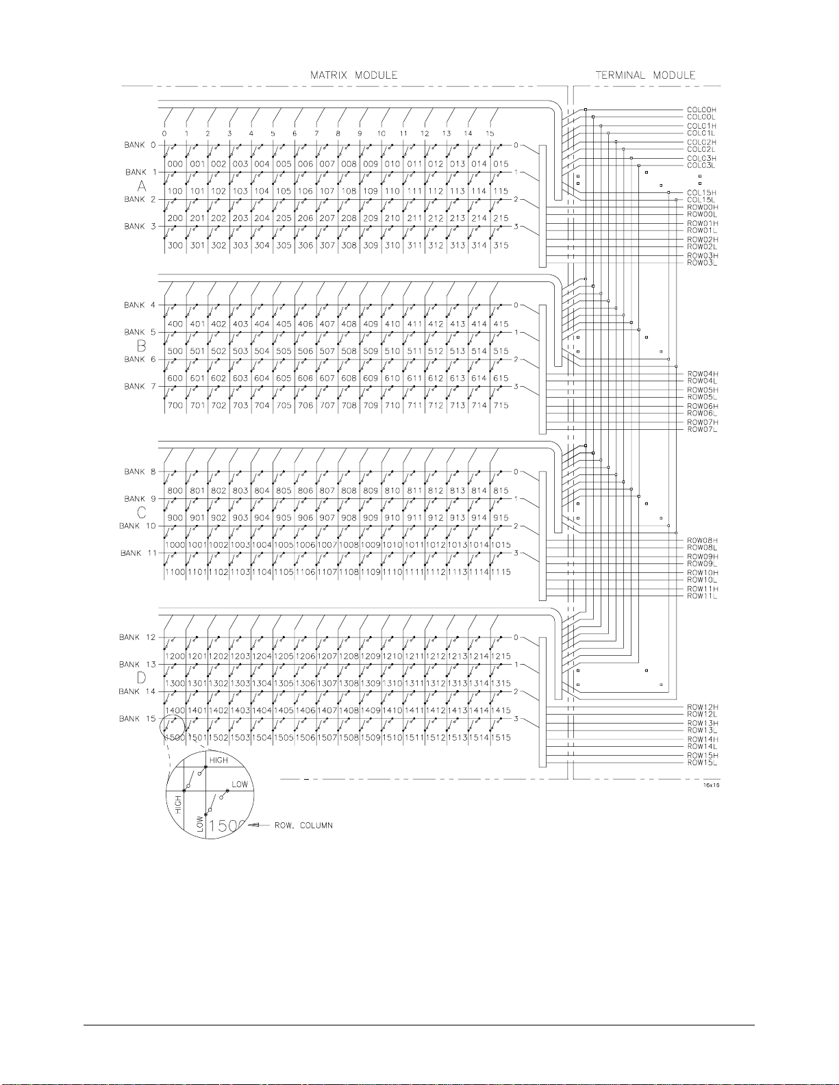
Figure 1-1. The E1465A 16 x 16 Matrix Module
12 Getting Started Chapter 1
Page 15
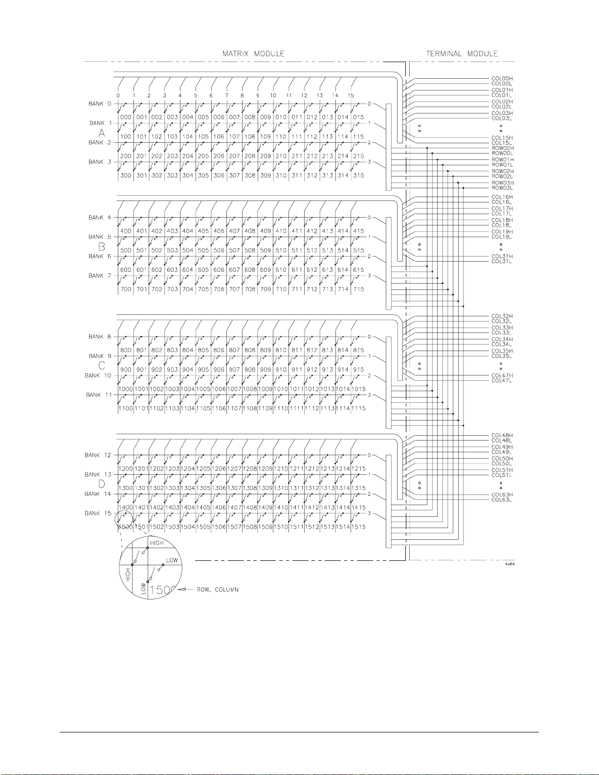
Figure 1-2. The E1466A 4 x 64 Matrix Module
Chapter 1 Getting Started 13
Page 16
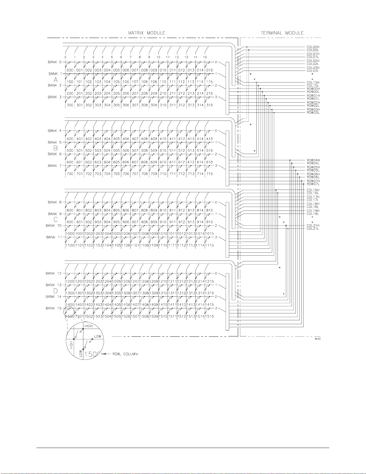
Figure 1-3. The E1467A 8 x 32 Matrix Module
14 Getting Started Chapter 1
Page 17

Instrument Definition
Agilent plug-in modules i nstal led in a mainframe or used with a n Agile nt
command module are treated as independent instruments, each having a unique
secondary GPIB address. Each instrument is also assigned a dedic ated e rror
queue, input and output buffers, status registers, and if applicable, dedicated
mainframe/command module memory space for readings or data. An
instrument may be composed of a si ngle plug- in m odule (such a s a c ounte r) or
multiple plug-in modules (for a switchbox or scanning voltmeter instrument).
Programming the Matrix
There are several ways you can program the ma trix modules. One way i s to
write directly to the registers . Thi s method can provide bet ter thro ughput
speed, however , i t req uir e s more knowledge of the ma trix design. See
Appendix B, “Matrix Registers” fo r inf or mati on on register progra mm ing.
Another way to program the matrix module is to use an Agilent command
module and SCPI (Standard Commands for P rogrammable I nstr ument s)
commands. With SCPI commands the Agilent command module parses the
commands and writes to the appropriate relay module register. The exam ples in
this manual use the SCPI programming language. See Appendix B, “Matrix
Registers” for examples on writing directly to the registers.
Specifying SCPI
Commands
Different controllers and different programming languages can be use d. The
examples in this manual , however, are based on the following configurations:
• HP 9000 Series 200 /300 computer runn ing BASIC
• HP Vectra computer (or compa ti bl e) wit h a n Agil e nt 82335A GPIB
Interface card ( with command li br ary) r unning Borland® Tur bo C
• Agilent E1499A V/382 computer running BASIC/UNIX, C (This
configuration is used in Appendix B for register-based programming).
See the C-Size VXIbus Systems Confi guration Guide for inf or mati on on
additional c onf igurations.
To address specific channels (relays) within a relay matrix, you must
specify the SCPI command and matrix channel list. The following are the
most commonly used SCPI commands:
Table 1-1. SCPI Commands
SCPI Command s Command Descri pt io n
CLOSe <channel_list>
OPEN <channel_list>
Closes the relays specified
Opens the relays specified
SCAN <channel_list>
Closes the relays specified, one at a time
Chapter 1 Getting Started 15
Page 18
The Channel List The channel list is a combination of the card number and the channel
numbers. The channe l lis t ta ke s the form of
ss = matrix card number (00-99)
rr = row number of the matr ix
cc = column number of the mat ri x
@ssrrcc where
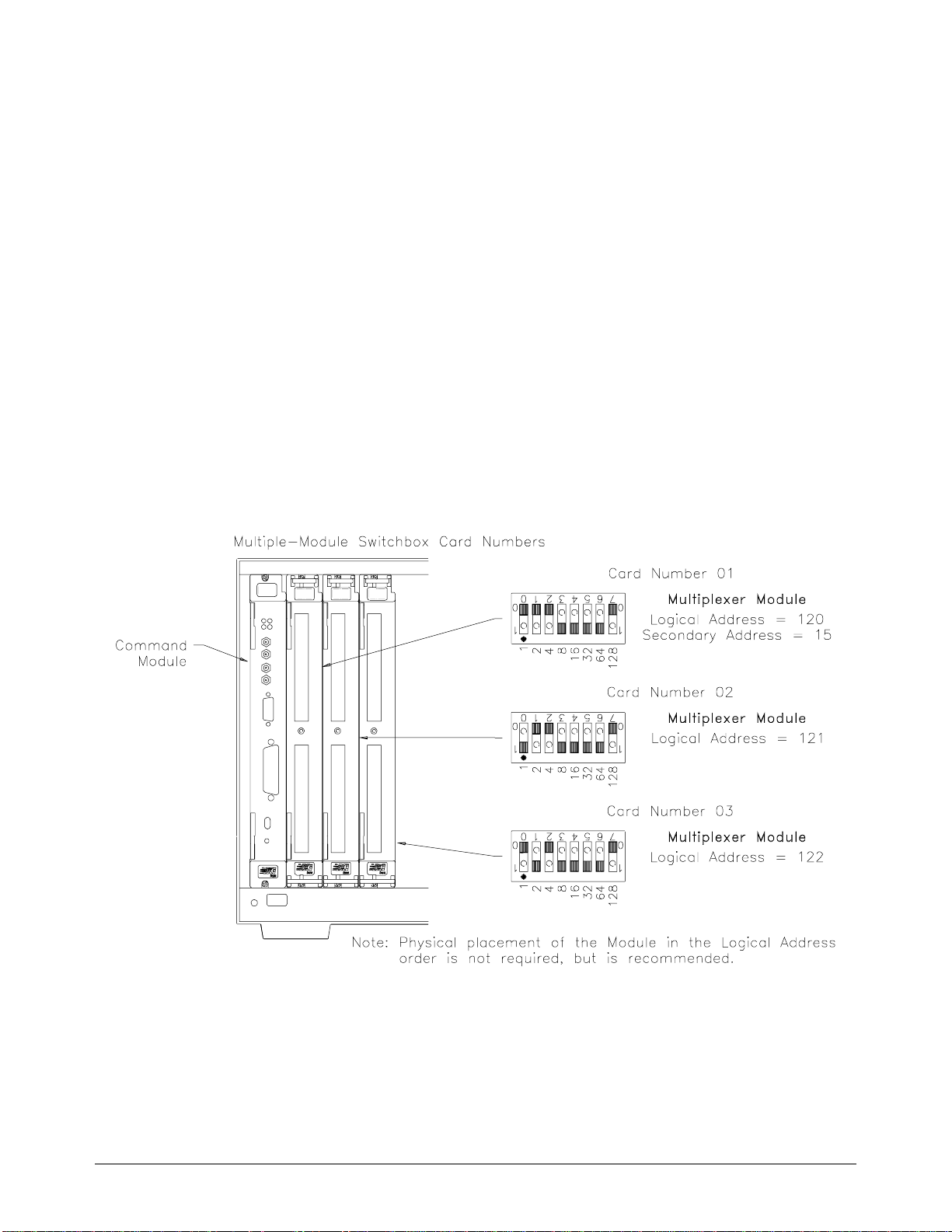
The Card Number The card number (ss of the channel list) id e ntifies the switch m odule within
a switchbox. The car d num be r ass ign ed dep en ds on the switch
configuration used. Leadi ng z e ro es can be ignored for the ca rd number.
• Single-Module Switchbox. In a single-m odule switc hbox
configuration, the card number is always 01.
• Multiple-Module Switch box. In a multiple-module switchbox
configuration, multiplexer module s a re se t to successive logical
addresses. The multipl exer module with the lowest logical address
is always card number 01. The c ard num ber with the ne xt suc cessive
logical address is 02, and so on. Figure 1-4 illustrate s the c ard num bers
and logical addresses of a typical multiple-module switchbox
configuration. In Chapter 2, an example of a ddressing a switchbox
configuration is shown in the "Using Multiple Mainframes" section.
Figure 1-4. Card Numbers in a Multiple-Module Switchbox
16 Getting Started Chapter 1
Page 19

The Channel Ad dresse s The channel address is the rrcc of the channel list. This address determines
which relay will be addressed. Use a comma (,) to form a channel list or use
a colon (:) to form a channel range. You can a ddre ss the following :
• single channels (@ssrrcc);
• multiple channels (@ssrrcc,ssrrcc,...);
• sequential channels (@ssrrcc:ssrrcc);
• groups of sequential channe ls ( @ssrrcc:ssrrcc,ssrrcc:ssrrcc);
• or any combina ti on of the a bove .
Table 1-2. Matrix Channel Numbers
Matrix Module Rows (rr) Columns (cc)
E1465A 16 x 16 Relay Matrix
E1466A 4 x 64 Relay Matrix
E1467A 8 x 32 Relay Matrix
Only valid channels can be accessed in a channel list or channel range.
Also, the channel range must be from a lower channel number to a higher
channel number. For example,
CLOS (@20303:10000) generates an error.
CLOS (@10000:20303) is acceptable, but
00 - 15 00 - 15
00 - 03 00 - 63
00 - 07 00 - 31
Chapter 1 Getting Started 17
Page 20

Initial Operation
BASIC
Two example programs follow which use BASIC and TURBO C languages
to get you sta rte d using the relay matrix switch mo dule. The first example
assumes an HP 9000 Series 200/300 controller and a General Purpose
Interface Bus (GPIB).
1
The second example assumes an HP Vectra PC (or
compatib le ) with an Agilent 8233 5A GPIB Interface card (wit h c omm a nd
library) running Borland® Turbo C .
The program close s row 03, column 12 of an Agilent E14 65A 16 x 16 Relay
Matrix at log ic a l addr e ss 120 (secondary addre ss = 120/8 = 15) and que ri es
the result. The result is returned to the controller and displayed
(1 = relay closed, 0 = relay open). See Chapter 5 for information on the
SCPI co mmands.
10 OUTPUT 70915; "*RST" ! Resets the module.
20 OUTPUT 70915; "CLOS (@10312)" ! Clos e s row 03, c olumn 12 on
module number 1.
30 OUTPUT 70915; "CLOS? (@10312)" ! Query channel 103 12.
40 ENTER 70915; Value ! Enter result into variable
Value.
50 PRINT Value ! Print resul ts (should print " 1"
to indicate that the cha nne l is
closed).
60 END ! Terminate program.
TURBO C #include <stdio.h>
#include <chpib.h> /*Include file for GPIB */
#define
#define MAT RIX 70915L /*Matrix default address*/
#define
#define
#define
1 (GPIB is the implementation of IEEE Std 488.1-1987 )
ISC 7L
TASK1 "*RST" /*Co m m and for a reset* /
TASK2 "CLOS (@ 10312)" /*Command to close row 3, column 12*/
TASK3 "CLOS ? (@ 10312)" /*Command to query row 3, c olumn 12*/
Continued on ne xt page .
18 Getting Started Chapter 1
Page 21

main()
{
char into[257];
int length = 256;
/*Output c ommands to matr i x*/
error_handler
error_handler
error_handler
(IOTIMEOUT (7L,5.0), "TIMEOUT");
(IOOUTPUTS (MATRIX, TASK1, 4), "OUTPUT command");
(IOOUTPUTS (MATRIX, TASK2, 15), "OUTPUT command");
error_handler (IOOUTPUTS (MATRIX, TASK3, 15), "OUTPUT command");
/*Enter from m atrix*/
error_handl er (IO E NTE RS (MA T RIX, into, &leng th) , "E NTER command");
printf("Now let’s see if the switch is closed: %s",into);
return;
}
int error_handler (int error, char *routine)
{
char ch;
if (error != NOERR)
{
printf ("\n Error %d %s \n", error, errstr(error));
printf (" in call to GPIB function %s \n\n", routine);
printf ("Press ’Enter’ to exit: ");
scanf ("%c", &ch);
exit(0);
}
retu rn 0;
}
Chapter 1 Getting Started 19
Page 22

Notes
20 Getting Started Chapter 1
Page 23

Configuring the Matrix Modules
Using This Chapter
This chapte r shows how to connect external wir ing to the matr ix modules
and how to conne c t multiple modules togethe r to f or m l arg e r ma tr ices. This
chapter conta ins the followi ng se c ti ons:
Chapter 2
• WARNINGS and CAUTIONS . . . . . . . . . . . . . . . . . . . . . . . Page 21
• Setting the Module Address Switch. . . . . . . . . . . . . . . . . . . . Page 22
• Selecting the Interrupt Line . . . . . . . . . . . . . . . . . . . . . . . . . . Page 23
• Installing the Switch Module in a Mainframe. . . . . . . . . . . . Page 24
• Wiring the Standard Terminal Module . . . . . . . . . . . . . . . . . Page 25
• Attaching the Standard Terminal Module to the
Relay Matrix Switch Module. . . . . . . . . . . . . . . . . . . . . . . . Page 27
• Connector Pin-Out . . . . . . . . . . . . . . . . . . . . . . . . . . . . . . . . . Page 28
• The Agilent E1465A Terminal Modul e. . . . . . . . . . . . . . . . . Page 29
• The Agilent E1466A Terminal Modul e. . . . . . . . . . . . . . . . . Page 30
• The Agilent E1467A Standard Terminal Mo dule . . . . . . . . . Page 31
• Creating Larger Matrices with the
Agilent E1465A/ E1466A/E1467A Modules. . . . . . . . . . . . Page 32
• E1467A Option 21 1 Expa ns ion Ter m inal Module. . . . . . . . . . . Page 3 6
• Attaching the Option 211 Expansion Terminal Module. . . . . . . . Page 38
• Using Multiple Mainframes. . . . . . . . . . . . . . . . . . . . . . . . . . Page 41
WARNINGS and CAUTIONS
WARNING SHOCK HAZARD. Only service-trained personnel who are aware
of the hazards involved should install, remove, or configure the
matrix modules. Remove all power sources from the mainframe
and installed modules before installing or removing a module.
CAUTION MAXIMUM INPUTS. The maximum voltage that can be applied
to any terminal is 200 Vdc/170 Vrms . The max imum curren t
that can be applied to any row or column is 1 A dc or ac peak.
The maximum power that can be applied to any terminal is 30 W
or 62.5 VA (resistive).
STATIC ELECTRICITY. Static electricity is a major cause of
component failure. To prevent damage to the electrical
components in the matrix module, observe anti-static
techniques when removing or instal ling th e module or when
working on the module.
Chapter 2 Configuring the Matrix Modules 21
Page 24
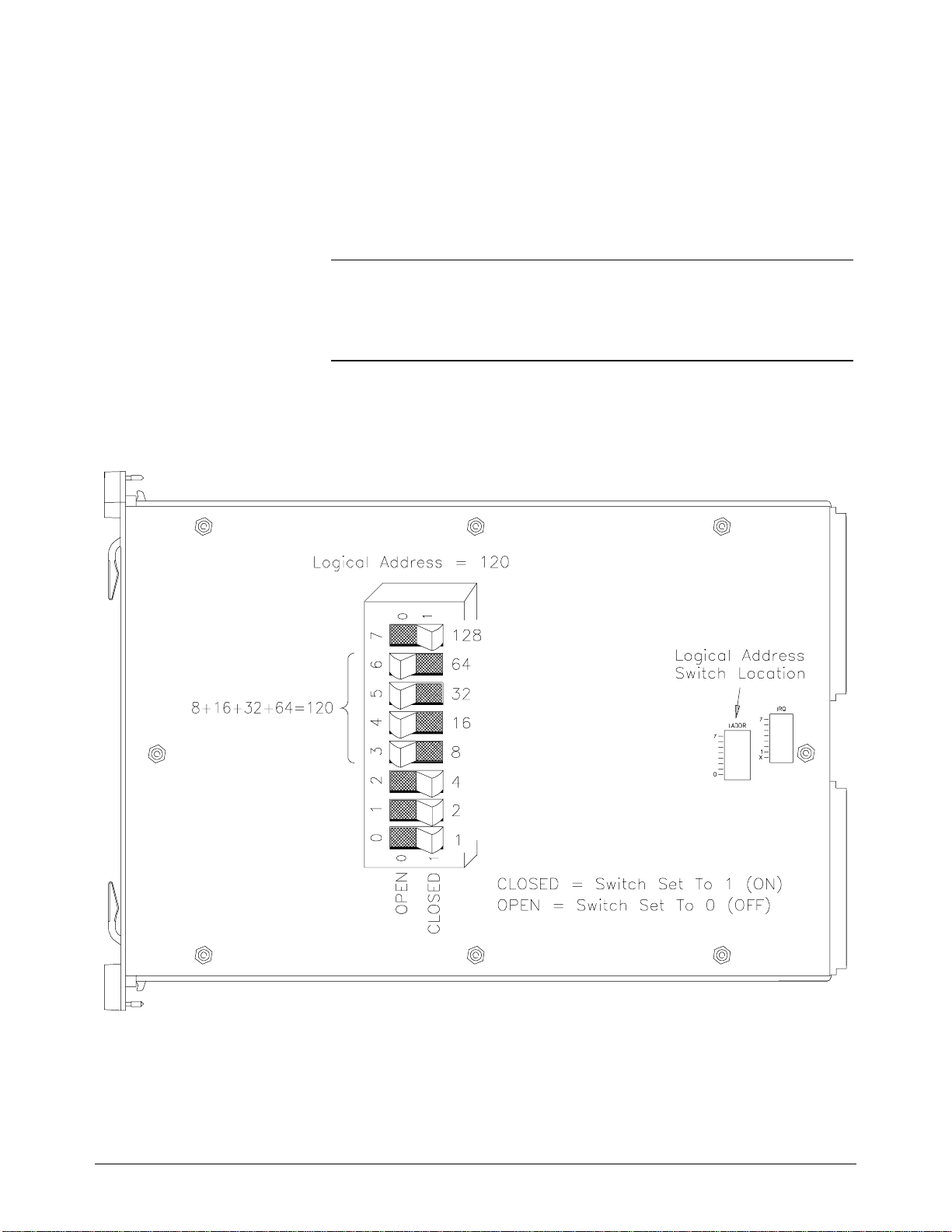
Setting the Module Address Switch
The logical address switch (LADDR) factory setting is 120. Valid address
values are from 1 to 255. The matrix mo dul e ca n be configured as a singl e
instrume nt or a s a switc hbox. If the matri x module is used wit h a n
Agilent E1406 A Com ma nd Module in a C-size mainf r a me , refer to the
C-Size VXIbus Sys tem s Co nfiguration Guide fo r addre ssing information.
Refer to Figure 2-1 for switch position information.
Note The address switc h se le c te d va lue must be a multiple of 8 if the m odule is
the first module in a "swi tc hbox" used with a VXIbus command module ,
and being instr uc ted by S CPI commands.
Figure 2-1. Selecting the Module Address
22 Configuring the Matrix Modules Chapter 2
Page 25
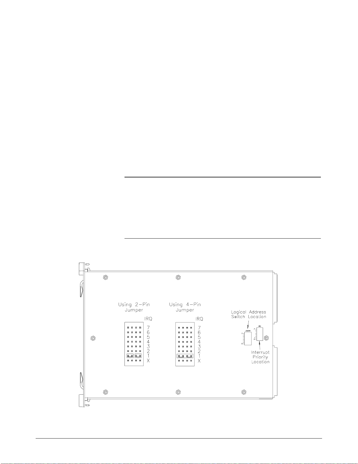
Selecting the Interrupt Line
The matrix module generate s a n interrupt afte r a ch an ne l ha s be e n cl ose d.
These inter ru pts are sent to, and ac knowledgement s a re rece ived from, the
command module (e.g., Agilent E1406A) via the VXIbus backpl an e
interrup t lines. For appl ic ations where the ma tr ix module is installed in an
Agilent 75000 Seri e s C mainframe and is a servan t of t he comma nd module,
the interr upt line jumper does no t ha ve to be moved. Refer to Figur e 2- 2 to
change the interrupt line .
You can select seve n different inte r ru pt line levels. Line X disa bl e s the
interrupt a nd should not be used . The module’s factor y se tting is line 1. To
change, remo ve the four -p in jumper (Agile nt pa r t number 1258-0247) f rom
the old line loc a tion and reinsta ll in the new line location. If you are sett ing
the interrupt line to something other than 1, see the Agilent E 1406
Command Module User’ s Manual for additional information. If the
four-pin jumper is not used, the tw o jumper locations must have the sa me
interru pt line selecte d.
Note When the Agile nt E1405/06 Com mand Module is the res ourc e m an ag er, the
interrupt li ne jumper
using an Agilent E1499A (Agilent V/382 ) wi th t he Agilent E1405/06
Command Module , inte r r upt lin e 2 sh ould be selected. Level X inte r rupt
line should not be use d unde r nor ma l ope rating condit ions. See the C-Size
VXIbus Systems Configuration Gui de fo r additional infor ma tion.
must be installe d in position 1. However, if you a re
Figure 2-2. Selecting the Interrupt Line
Chapter 2 Configuring the Matrix Modules 23
Page 26
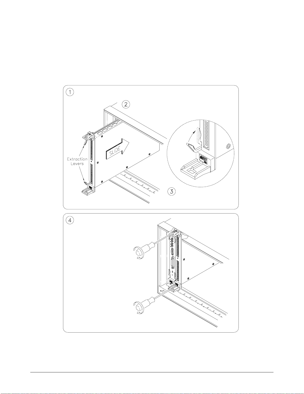
Installing the Relay Matrix Switch Module in a Mainframe
The Agilent E1465/66/67A may be inst a lled in any slot (exc ep t slot 0) in a
C-size VXIbus mainf r ame . Refer to Figure 2-3 to i nstall the modu le in a
mainframe.
Set the extracti on levers out.
Slide the module i nto any sl ot (e xcept slot 0) until
the backplane connectors touch.
Tighten the top and bottom screws to
secure the module to the mainframe .
NOTE: The extraction
levers will not seat the
backplane connec to rs on
older VXIbus mainframes.
You must manually seat the
connectors by pus hing i n
the module until the front
panel is flush with the front
of the mainframe. The
extraction levers may be
used to guide or remove t he
To remove the modu le from the mainf r am e,
reverse the proced ure .
Seat the module into the
mainframe by pushing in the
extraction leve rs.
Figure 2-3. Installing the Switch Module in a VXIbus Mainframe
24 Configuring the Matrix Modules Chapter 2
Page 27
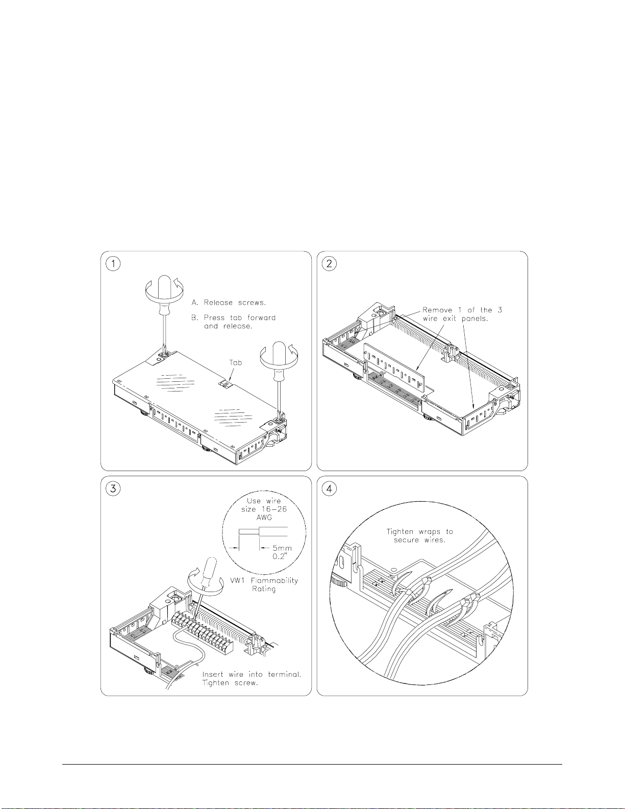
Wiring the Standard Terminal Module
User wiring to the matr ix m odules are to the High (H) and Low (L ) term ina l
connections . Figure s 2- 4 a nd 2-5 show the rudime nts o f the term inal
module assembly. Expansion connectors allow for creating larger matrices
(see later in this c ha pte r ). For i nf orma ti on on the E1467A Option 211
Matrix Expans ion Terminal Modul e , see the se c ti on de dicated to that
product late r in this chapte r.
Maximum ter mi na l wire siz e is No. 16 AW G. Wir e ends should be stripped
6 mm (0.25 in.) an d ti nne d. When wiring all c h anne ls, use a smalle r g au ge
wire (No. 20 - 22 AWG).
Remove clear cover.
Make connections.
Screw Type
Remove and retain wiring exit panel.
Route wiring.
Figure 2-4 . Wiring the Standard Termi na l Module
Continued on next page.
Chapter 2 Configuring the Matrix Modules 25
Page 28
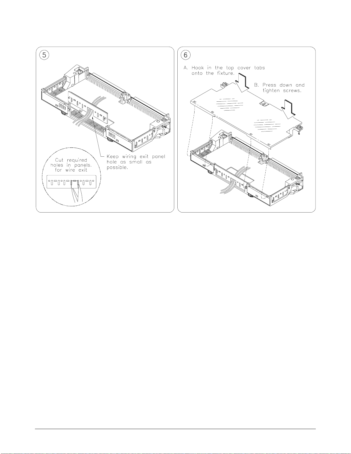
Replace wiring ex it pan el.
Replace clear cover.
Figure 2-5 . Wiring the Standard Termi na l Module
Continued f rom previous page.
26 Configuring the Matrix Modules Chapter 2
Page 29
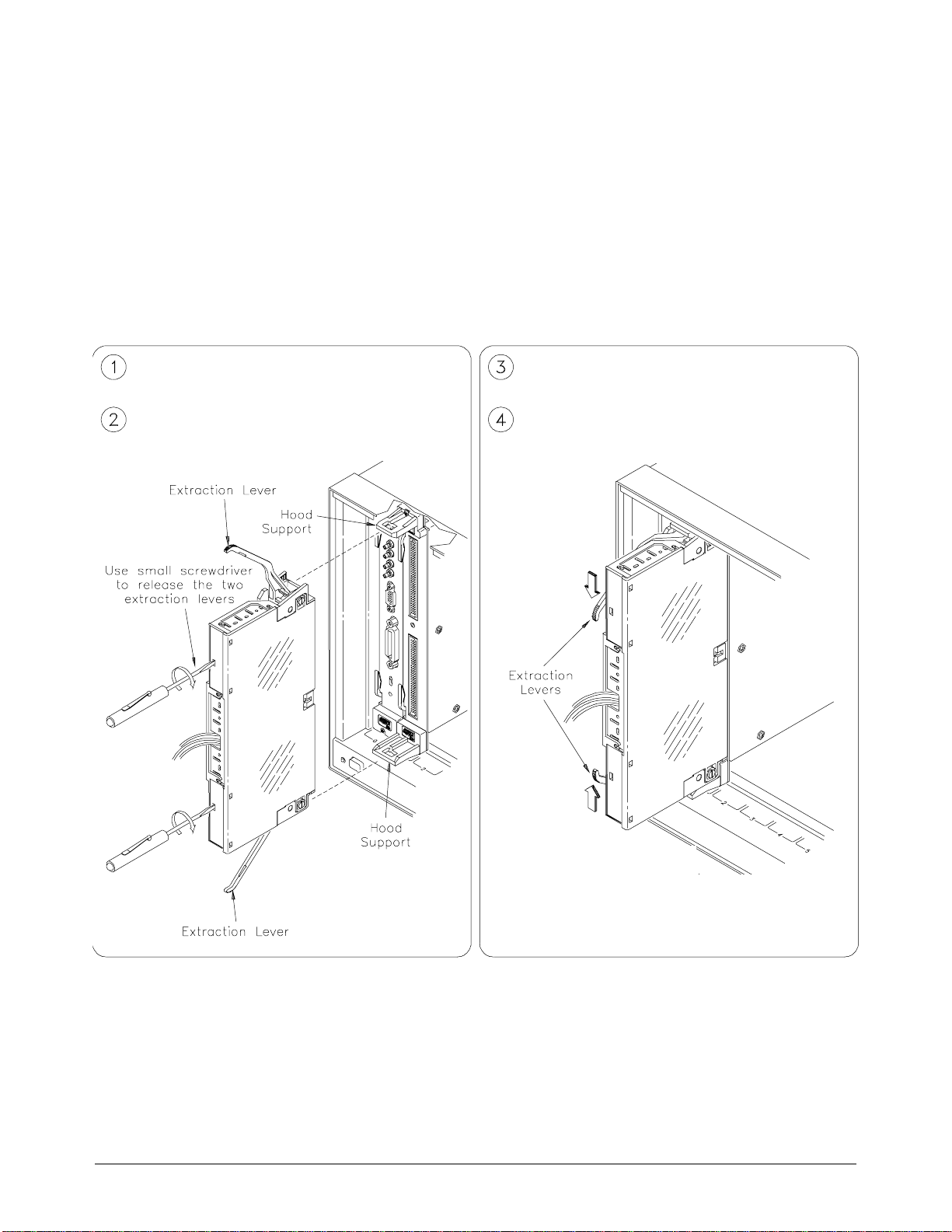
Attaching the Standard Terminal Module to the Re lay
Matrix Switch Module
Figure 2-6 shows how to install the standa r d te rminal modules in the relay
matrix switc h module. For inform a ti on on installing t h e Ag il en t E1467A
Option 211 Matrix Expansion Terminal Module, see the se c ti on de dicated to
that product later in th is c ha pter.
Extend the extra ct ion le ver s on t he term inal
module.
Align the terminal module con nec to rs to the Relay
Matrix Switch Mod ule, usi ng t he tw o
Apply gentle pr essure to attach the ter minal
module to the Relay Matrix Switch Module.
Push in the extraction levers to lock the terminal
module into place on the Relay Matrix Switch
Module.
To remove the terminal m odul e fro m the R ela y Matr ix
Switch Module, use a small screwdriver to release the
two extraction levers and pus h bot h l ever s out
simultaneously to fre e it f rom t he Re lay M at rix Sw i tch
Module.
Figure 2-6. Attaching the Standard Terminal Module
to the Relay Matrix Switch Module
Chapter 2 Configuring the Matrix Modules 27
Page 30
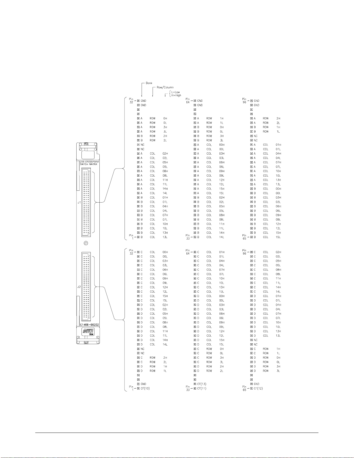
Connector Pin-Out
Figure 2-7 shows the fron t pa ne l of the Agilent E1465/66/67A and the
connector pin- out that mates to the termina l module.
Figure 2-7. Relay Matrix Switch Module Pin-Out
28 Configuring the Matrix Modules Chapter 2
Page 31
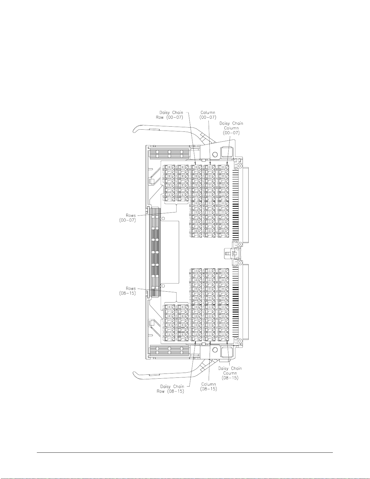
The Agilent E1465A Terminal Module
Figure 2-8 shows the Agilent E1465A terminal module co nne c tor s and
associated row/column designators. Refer to “Creating Larger Matrices
with the Agilent E146 5/66/67A Modu le s” la te r in this chapt e r for
information on using the expansion connector.
Figure 2-8. The Agilent E1465A Termi nal Module
Chapter 2 Configuring the Matrix Modules 29
Page 32
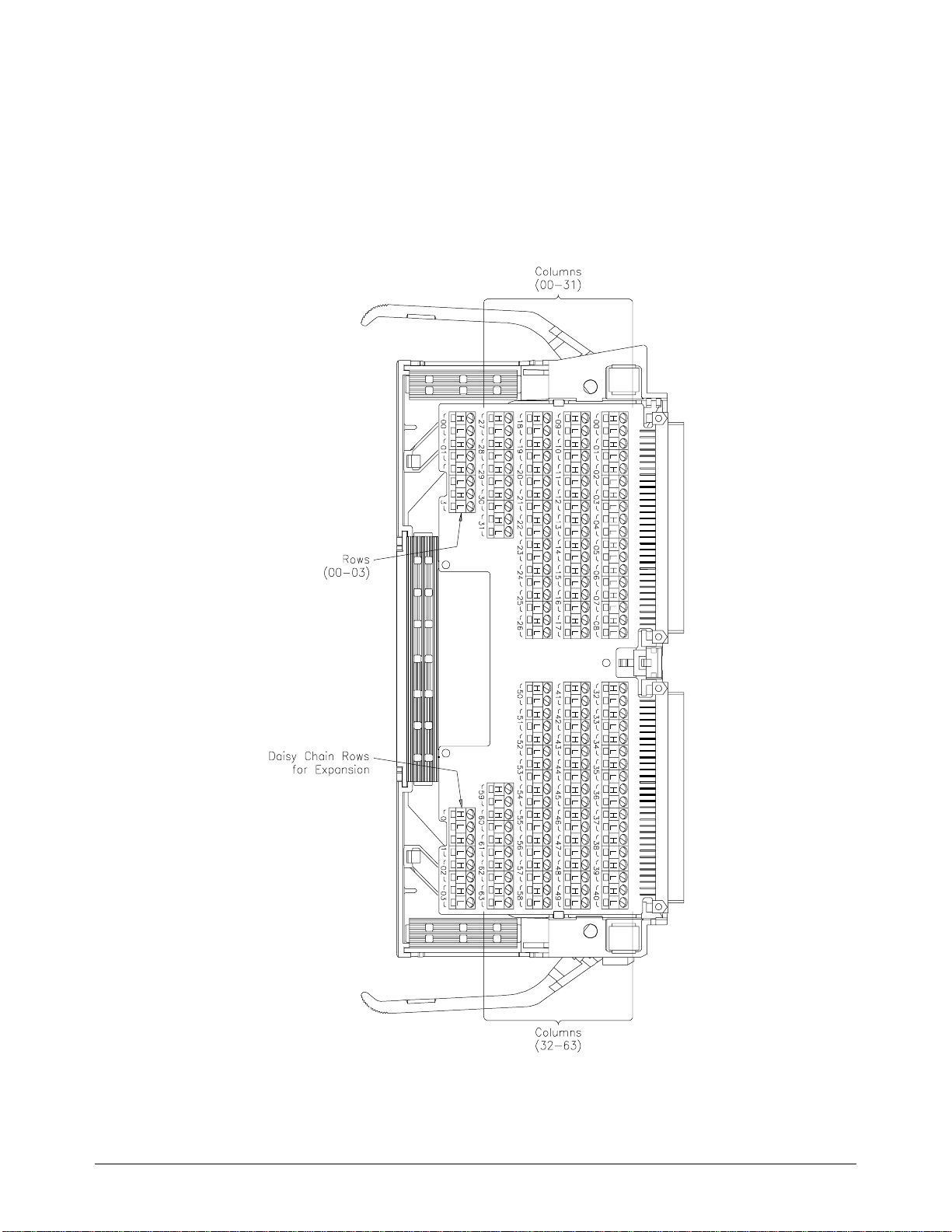
The Agilent E1466A Terminal Module
Figure 2-9 shows the Agilent E1466A terminal module co nne c tor s and
associated row/column designators. Refer to “Creating Larger Matrices
with the Agilent E146 5/66/67A Modu le s” la te r in this chapt e r for
information on using the expansion connector.
Figure 2-9. The Agilent E1466A Terminal Module
30 Configuring the Matrix Modules Chapter 2
Page 33
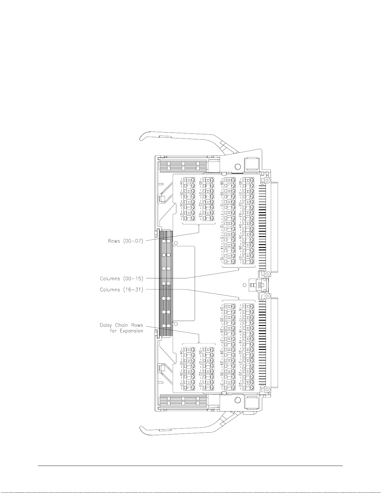
The Agilent E1467A Standard Terminal Module
Figure 2-10 shows the Agilent E1467A standa r d ter mi na l m odule
connectors and associated row/column designators. Refer to “Creating
Larger Matrices with the Agilent E1 465/ 66/67A Modules” l ate r in this
chapter for inf or mation on using the e xpa nsion connector .
Figure 2-10. The Agilent E1467A Standard Terminal Module
Chapter 2 Configuring the Matrix Modules 31
Page 34

For information on the Agilent E1467A Option 211 Matrix Expansion
Terminal Mod ule , refer to the sec ti on de dicated to that pr oduc t later in this
chapter.
Creating Larger Matrices with E1465/66/67A Modules
You can create larger matrices with the matrix modules by using the
Agilent E1466-80002 Daisy Chain Expa nsion cable. Wit h larger mat r ice s
more crosspoints become available. A full C-size cardcage can have up to
3,072 two-wire crosspoints. You can make a larger matrix by connecting t he
rows or columns of one terminal module to the corresponding rows or c olumns
of the next terminal m odule. Only the Agilent E1465A has a c olumn
expansion.
Module
Configuration
When using m ultiple mod ule s, the modules should be configur ed as a
switchbox. That is, the first switch car d (module) has a logi cal add ress that
is a multiple of 8, and succeeding switch cards have sequential logical
addresses. For ex am ple, if you use the ma trix default addre ss of 120 for the
first card, the remai ni ng c ards in the switchbox would have logical
addresses of 121, 122, 123, and so on. See the C-Size VXIbus Syst ems
Configurati on Guide for additiona l information on switchbox configur a ti ons.
Module Address When using multiple modules confi gur e d as a switc hbox, you must addr e ss
the modules as a swi tchbox. For example, if you wa nt to close row 00,
column 05 on the se c ond c a rd , yo u would use the followi ng SC PI c omm a nd:
CLOSe (@20005)
Creating a 32 X 32
Matrix
Figure 2-11 sh ows ho w to c onn ect fou r Agi lent E 1465 A 16 x 16 m o dule s t o
create a 32-row by 32-column matrix. This config uration requires 16 Ag ilent
E1466-80002 Daisy Chain Expansion cables The daisy chain rows of modules 1
and 3 are connected to the rows of cards 2 and 4 (this increas es the number of
columns). The daisy chain columns of cards 1 and 3 are connected together, and
the daisy chain columns of cards 2 and 4 are connected together. The foll owing
table summar izes which cards support whic h r ows a nd c olumns:
Rows/Columns Cards (Modules)
Rows 00 - 15 Cards 1 and 2
Rows 16 - 31 Cards 3 and 4
Columns 00 - 15 Cards 1 and 3
Columns 16 - 31 Cards 2 and 4
To connect row 16 to c olumn 15 use the following SCPI comm an d:
32 Configuring the Matrix Modules Chapter 2
Page 35
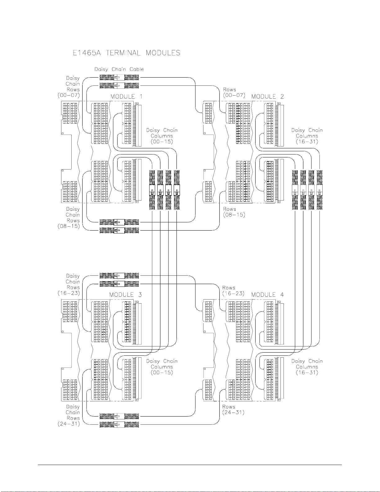
Figure 2-11. Creating a 32 X 32 Matrix
Chapter 2 Configuring the Matrix Modules 33
Page 36
CLOSe (@30015)
See Figure 2-11. This command will close the r ela y on c ard 3, row 00,
column 15 .
Creating a 4 X 256 Matrix Figure 2-12 shows how to con ne ct four Agilent E1466A 4 x 64 modules to
create a 4-row by 256-column matrix. This configuration requires three
Agilent E1466-80 002 Da isy Chain Expansion cables. The daisy chai n rows
of the first modu le are co nne cte d to the rows of the next m odule. The daisy
chain rows of the sec ond module are then c onnected to th e rows of the next
module, and so on. You can continue this pattern to cr eate even larger
matrices.
Figure 2-12. Creating a 4 X 256 Matrix
34 Configuring the Matrix Modules Chapter 2
Page 37
To connect row 03 to column 255, you would use the following SCPI
command:
CLOSe (@40363)
See Figure 2-12. This command will close the r ela y on c ard 4, row 3,
column 63 .
Creating an 8 X 96
Matrix
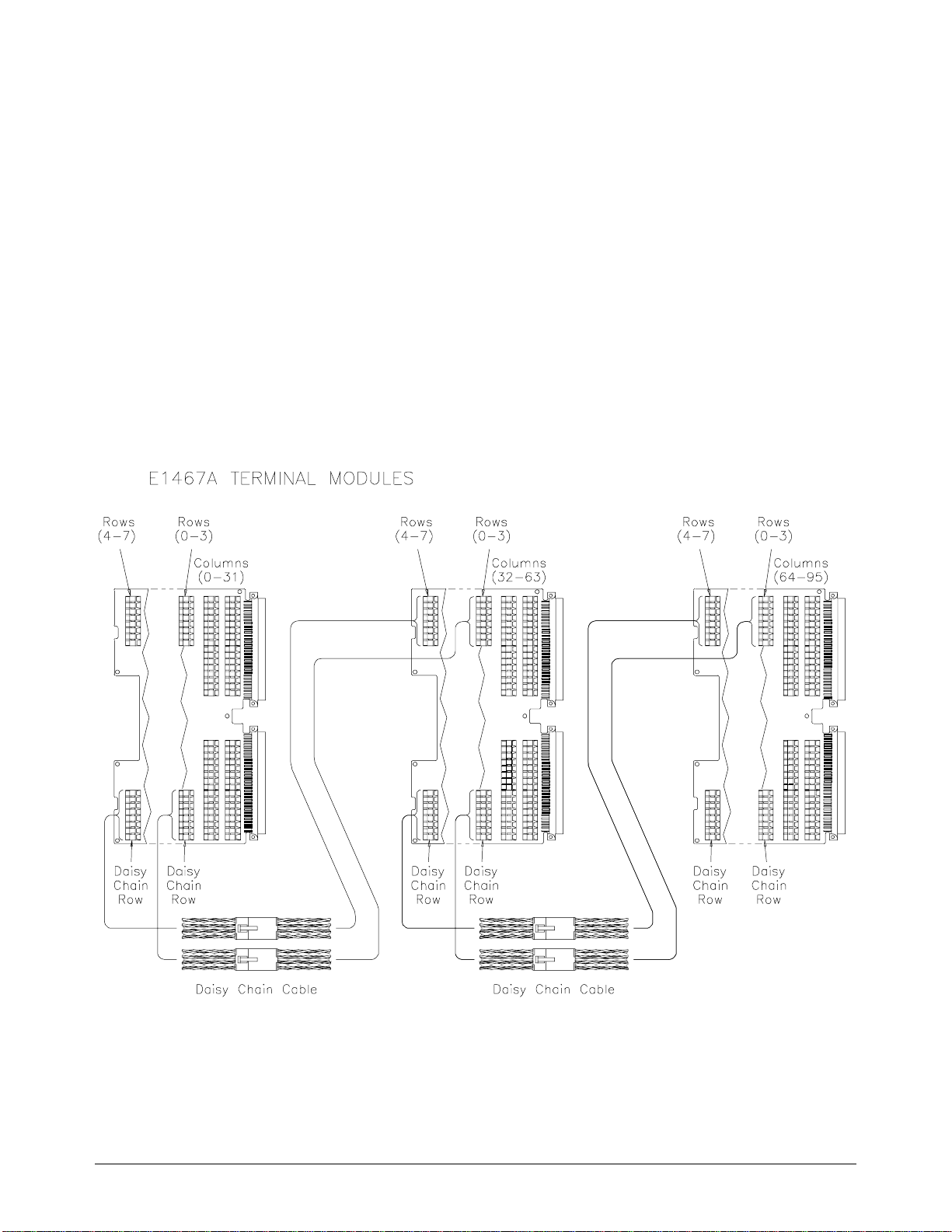
Figure 2-13 show s how to connect three Agilent E1467A 8 x 32 modules to
create an 8-row by 96-column matrix. This configuration requires four
Agilent E1466-80 002 Da isy Chain Expansion cables. The daisy chain rows
of the first module are connected t o the r ows of the ne xt module. The daisy
Figure 2-13. Creating an 8 X 96 Matrix
Chapter 2 Configuring the Matrix Modules 35
Page 38

chain rows of the se cond module are then connected to the rows of the next
module, and so on. You can continue this pattern to create e ven larger
matrices.
To connect row 4 to co lum n 32, e xe cu te the f ollowing SCPI comma nd:
CLOSe (@20400)
See Figure 2-13. This command c lose s the rel ay on c ard 2, r ow 4, colu mn 00.
E1467A Option 211 Matrix Expansion Terminal Module
When chaining more than two Agilent E1467A 8x32 matrix modules, you
may wish to use the Agilent E1467A Option 211 Matrix Expan sion
Terminal Mod ule in place of the sta nda r d Agilent E1467A terminal module .
Option 211 provides an 8x32 matrix configuration that can be expanded easily
via the quick-acc ess front panel cable connectors with quick connection and
disconnection of expansion cables, and optimizes cable count and
organization.
This module i s used with the Agilent Z2220A series coax cabl es whic h a re
available in a vari e ty of le ngths and conne ctions, depending on your need.
Compared to the daisy-chain cable which requires each wire to be screwed
into the screw te r mi na l, the Agi le nt E1467A Option 211 te rminal module
and Agilent Z2220A series coax cables provide quicker access and easier
cable connec ti ons. (Agilent wil l cu st om-quote cables to match your spe ci fic
applicati on. Cont a ct your Agilent Sales Repre se nt at ive for assistance .)
Note The Option 211 mat ri x e xpa nsi on terminal modu le is specially des ign ed for
use with the Agilent E1467A and cannot be use d with either the Agil e nt
E1465A or Agilent E1466A matrix modul e . Opt ion 211 r ep lac es Opti on
201, which is com p atible with the ea rl ier model of the Agilent E1467A.
8-Channel Row
Connectors
16-Chann el Colu mn
Connectors
The Agilent E1467 A Option 211 Matrix Expa nsion Terminal Module ha s
one 20-pin connector which contains a high and low conne c ti on pe r row
plus a connector shi el d pi n. A parallel row connector is provided for easy
chaining of multiple modules. Shield pins are common t o al l c olumn
connectors.
Two 34-pin conn ect or s are provided which conta in a high and low
connection per co lumn plus a column co nne c tor shi e ld pin. A parallel
column connector is provide d f or easy c ha ining of mult iple modules. Shi e ld
pins are common to all column connectors.
36 Configuring the Matrix Modules Chapter 2
Page 39
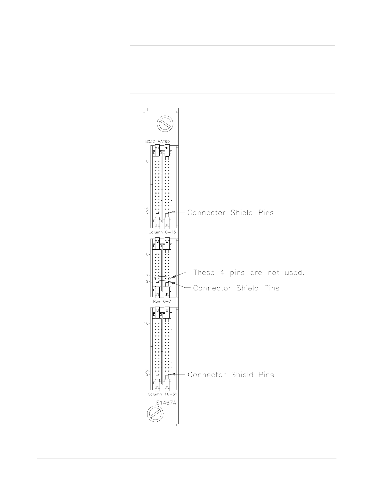
Note The connecto r sh ie ld pins allow you to interc onne c t co l u mn and row shields
when shielded t w ist e d- pa ir cables are used. A 3-screw te rminal block
resides insi de the te rminal module, a llowing connec ti on of the c olumn or
row cable shields to each other or to chassis ground.
Figure 2-14. Option 211 Terminal Module Front Panel
Chapter 2 Configuring the Matrix Modules 37
Page 40

Option 211
Expansion
Figure 2-14 show s the fro nt pa ne l of the Agilent E1467A Option 211 Matrix
Expansio n T e rm inal Module.
Terminal Module
Front Panel
Attaching the E1467A Option 211 Matrix Expansion
Terminal Module
The following te xt and Figure 2-15 provide installat ion instructions for the
Option 211 termi na l m odule.
You must first install the Agilent E1467A Relay Matrix Switch Module in
the mainframe, ensuring that the extraction levers are locked in place (see
Figure 2-3 earlie r i n this chapter).
1. Using a flat-bla de sc r ewd rive r , tur n the e xpa nsi on terminal modu le ’ s
two pawl latch sc re ws co unterclockwise until the pawl i s at the e nd of
its travel. This will rotate the pawl latches out of the way of the sw itc h
module’s hood supports when joining the two modules together.
2. Align t he te rm inal module connectors with the relay ma trix switch
module conn ect or s. Enga ge the co nne c tors of the two modules, using
the hood sup ports as guides. Firm ly push the exp an sion terminal
module tow a rd the sw it c h module until the extraction le ve r s on the
switch module fit int o the "pockets" on the side of the te rminal module .
3. Turn each pawl la tc h sc r e w cloc kwise, ensuring th at the pa wl r otates
into posit ion (90°) i n the recta ngular hol e in the hood support. Once the
pawl is properly positioned, turn the screw until snug but not tight. If
the pawl does not easily rotate into th e hole on t h e first try, make sure
the two modules are e ngaged snugly. If this still does not allow enough
clearance for the pawl to rotate into the hole, loosen the pawl lat ch
screws (counterclockwise) until the pa wl c lears the hole . Then re-snug
the screws .
To remove t he exp ansion termi nal module, loosen the pawl la tc h sc r ews,
rotating the pa wls 90° so that they move out of the rectangular hole. Then
firmly pull on the expansion terminal module until the connectors are no
longer engaged.
38 Configuring the Matrix Modules Chapter 2
Page 41
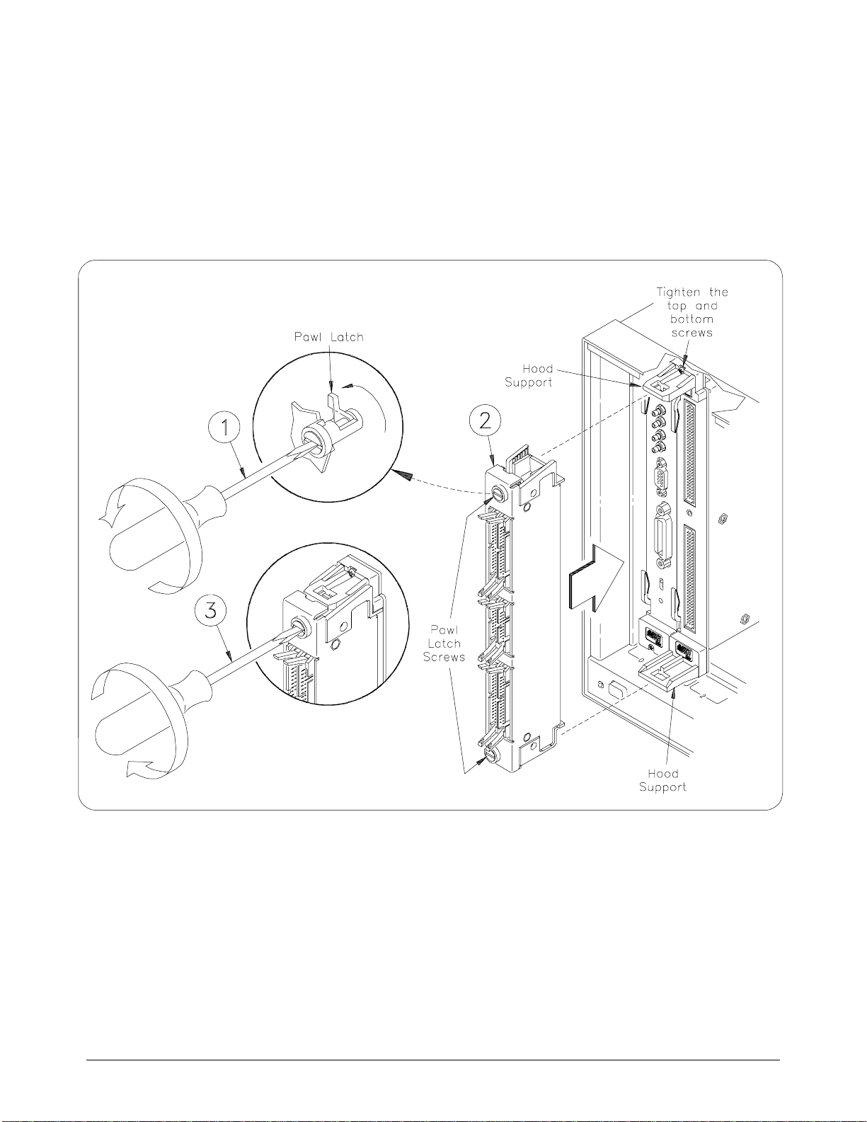
Attaching Option 211
Figure 2-15. Attaching the Option 211 Terminal Module
Chapter 2 Configuring the Matrix Modules 39
Page 42
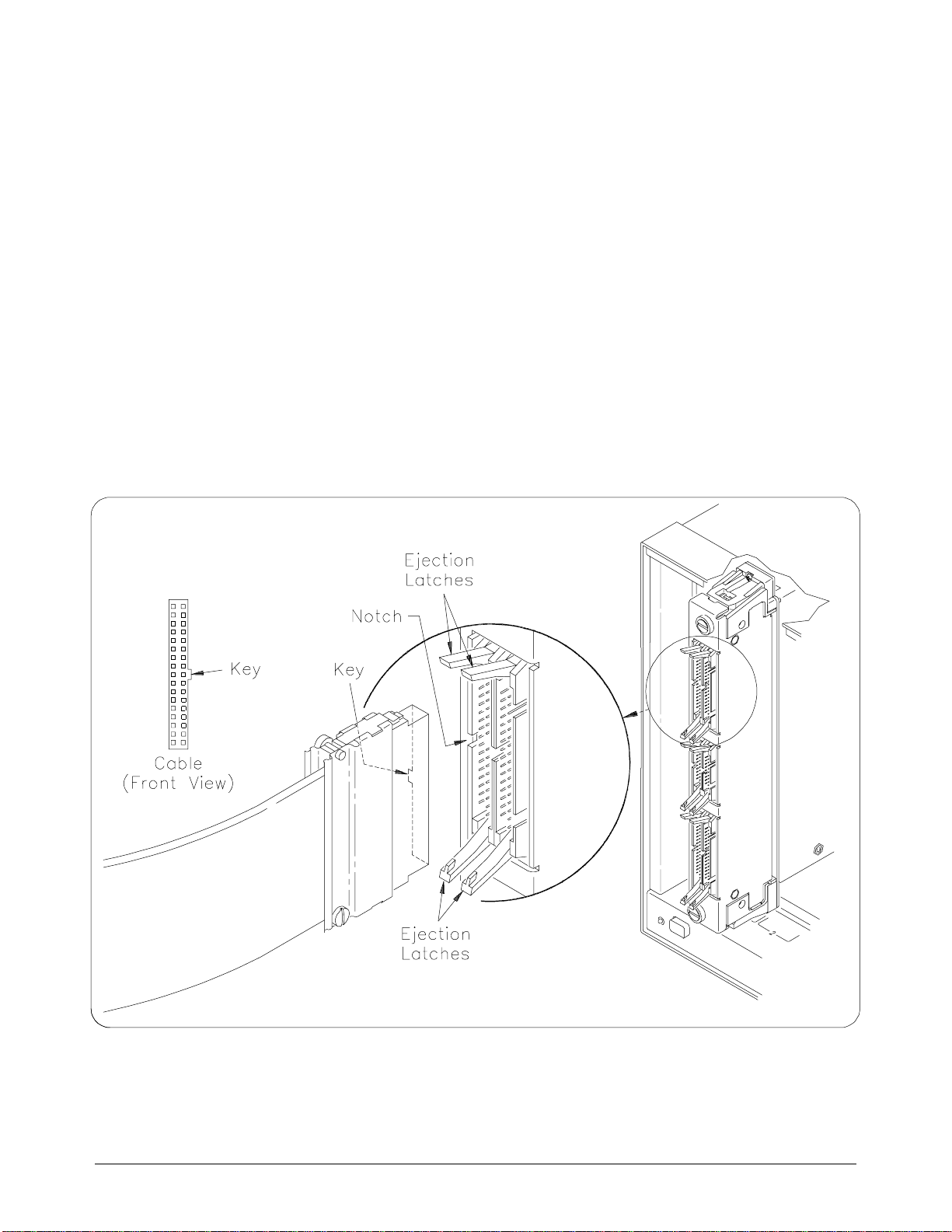
Attaching Cables 1. Push th e expa nsion terminal module ’s e je c ti on la tches away f ro m the
center of the con ne ct or you a r e go ing to plug the cab le into.
2. Inspect yo ur cable to find the "key" in the middle of one side of the
connector. (The key is a bump/raised area.) Hold the cable with the
key on the left si de to a lign with the corr es ponding notch in the
expansion term ina l module connec tor.
3. Firmly ins ert the cabl e int o the e xpa nsion module con ne ctor , pushing
until the ejection latches snap inward and grip the ends of the cable
connector.
To remove the cable, pull both ejection latches away from the cable,
disengaging the connectors.
Attaching Cables
Figure 2-16. Attaching C a ble s to the Expansion Te r m inal Module
40 Configuring the Matrix Modules Chapter 2
Page 43
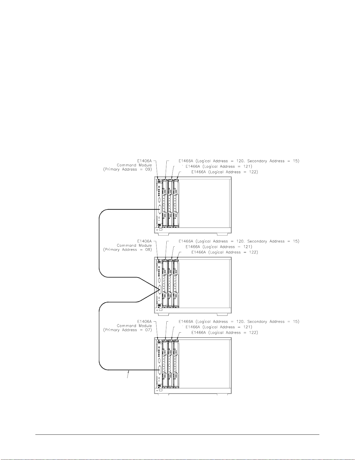
Using Multiple Mainframes
There are two ways to connect multiple mainframes together. One way is to
connect the mainf r a me s by way of GPIB and a ssign each mainfra me a
different address. See Figure 2-17. The switch modules in each mainframe
are then configure d a s swit c hboxes. The switchbo x card numbers are 1, 2,
3, etc. in each mainframe (each mainframe has a different address). To
address the second module in the second mainframe, use the following SCPI
command:
OUTPUT 70815; "CLOSe (@20001)"
In the above command, the computer selec t code is 7, the command module
primary address is 08, and and the m atr ix module’s seconda ry add ress is 15.
The address (@20001) selects card 2, row 00, co lum n 01.
GPIB
Figure 2-17. Larger Matrices with Multiple Mainframes
Chapter 2 Configuring the Matrix Modules 41
Page 44
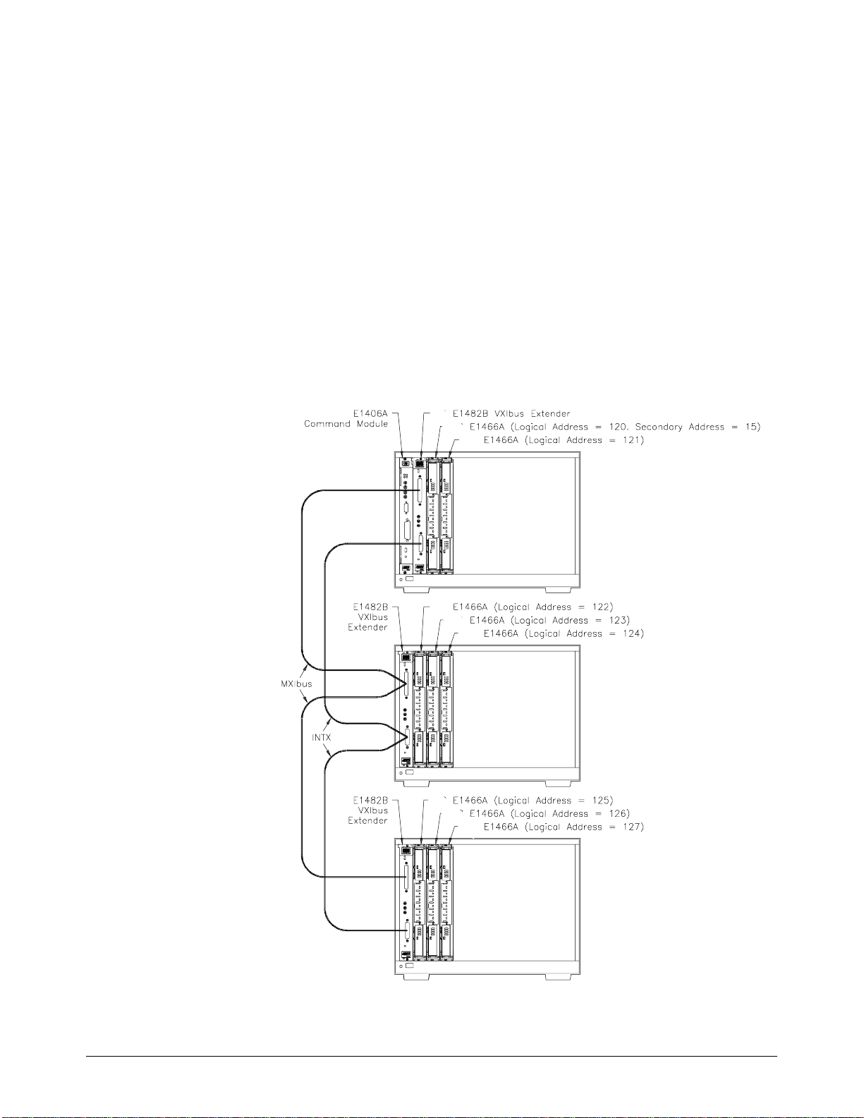
Another way to connect multiple mainframes is to use the Agilent E1482B VXIbus
Extender card. This card allows you to connect multiple mainframes via the
MXIbus to look like a single mainfra m e . In Figure 2-18, the swi tc h m odules are
again configured as a switchbo x. Howe ve r, the switchbox ext e nds across multiple
mainframes. The switchbox card numbers are 1, 2, 3, 4, 5, etc. extending across all
the mainframes (the mainframes act as a single mainframe). To address the second
card in the sec ond m a inframe, use the foll owing SCPI comm an d:
OUTPUT 70915; "CLOSe (@40001)"
In the above command, the computer select code is 7, the command module
primary address is 09, and the matrix module’s sec ondary address is 15 . The
address (@40001) selects card 4, row 00, c olumn 01. (See the VX I-MXI Bus
Extender Use r’s Manual for speci fic information on the A gil e nt E 1482B VXIbus
Expansion Module’s configura ti on. )
Figure 2-18. Creating Larger Matrices Using the MXIbus
42 Configuring the Matrix Modules Chapter 2
Page 45

Using This Chapter
This chapter uses typical examples to show how to use the matrix modules.
See Chapter 4, “Relay Matrix Command Reference” for command
information. Chapter contents are as follows:
Chapter 3
Using the Matrix
• Matrix Commands . . . . . . . . . . . . . . . . . . . . . . . . . . . . . . . . . Page 43
• Power-On and Reset Conditions . . . . . . . . . . . . . . . . . . . . . . Page 44
• Module Identification. . . . . . . . . . . . . . . . . . . . . . . . . . . . . . . Page 44
• Switching Channels . . . . . . . . . . . . . . . . . . . . . . . . . . . . . . . . Page 46
• Scanning Channels. . . . . . . . . . . . . . . . . . . . . . . . . . . . . . . . . Page 47
• Querying the Matrix Module . . . . . . . . . . . . . . . . . . . . . . . . . Page 51
• Using the Scan Complete Bit. . . . . . . . . . . . . . . . . . . . . . . . . Page 52
• Recalling and Saving States. . . . . . . . . . . . . . . . . . . . . . . . . . Page 53
• Detecting Error Conditions . . . . . . . . . . . . . . . . . . . . . . . . . . Page 54
• Synchronizing the Matrix Module. . . . . . . . . . . . . . . . . . . . . Page 56
• Understanding the Relay Matrix . . . . . . . . . . . . . . . . . . . . . . Page 57
Matrix Commands
Command Description
[ROUTe:]CLOSe <channel_list>
[ROUTe:]CLOSe? <channel_list>
[ROUTe:]OPEN <channel_list>
[ROUTe:]OPEN? <channel_list>
INITiate[:IMMediate]
All examples in th is c ha pter use an GPIB select cod e of 7, primary address
of 09, and secondary address of 15 (LADDR = 120) for the matrix module.
Table 3-1 expla ins some of the comm a nds used in this cha pt er. Re fer to
Chapter 4 for a ddi tional infor mation on these co mmands.
Table 3-1. Matrix Commands Used in Chapter 3
Closes the channels in the channel list.
Queries the state of the channels in the channel list.
Opens the channels in the channel list.
Queries the state of channels in the channel list.
Starts the scan sequence and closes the first channel in the
channel list.
[ROUTe:]SCAN <channel_list>
TRIGger:SOURce <source>
Defines the channel list to be scanned. Channels specified
are closed one at a time.
Selects the trigger source to advance the scan.
Chapter 3 Using the Matrix 43
Page 46

Power-On and Reset Conditions
The matrix modules use latc hing relays and th e re la y state remains
unchanged during power-up and power-down. If, however, an Agilent
E1406A Comman d Module is used, the fi rmwa re opens all relays duri ng
power-up and a when a
the paramete r s a nd de f au lt values for the ma tr ix module as de sc ri be d in this
chapter.
Table 3-2. *RST (Reset) Default Conditions and Values
Parameter Default Description
ARM:COUNt 1 Number of scanning cycles is 1.
TRIGger:SOURce IMM Will advance scanning cycles
INITiate:CONTinuous OFF Number of scanning cycles set by
OUTPut[:STATe] OFF Trigger output from EXT or TTL
*RST (reset) command is executed. Ta ble 3- 2 lists
automatically.
ARM:COUNt.
sources is disabled.
Module Identification
The following short programs use the *RST, *CLS, *IDN?, CTYP?, and
CDES? commands to reset and identify the matrix modules.
BASIC
10 DIM A$[50], B$[50], C$[50] ! Dimensions three string
20 OUTPUT 70915; "*RST; *CLS" ! Outputs the commands to
30 OUTPUT 70915; "*IDN?" ! Queries for modul e
40 ENTER 70915; A$ ! Enters the results into A$.
50 OUTPUT 70915; "SYST:CDES? 1" ! Output command for module
60 ENTER 70915; B$ ! Enters the results into B$.
70 OUTPUT 70915; "SYST:CTYP? 1" ! Outputs command for module
80 ENTER 70915; C$ ! Enters the results into C$.
90 PRINT A$, B$, C$ ! Prints the contents of variable
120 END
variables to fifty charact er s.
reset and cle ar Status Registe r.
identification.
description.
type.
A$, B$, and C$.
44 Using the Matrix Chapter 3
Page 47

TURBO C #include <stdio.h>
#include <c hpi b. h>
#define ISC 7L
#define MATRIX 70915L
#define TASK 1 " *RST;*CLS;*I D N?" /*Reset, cl ear, and quer y i dentification*/
#define TASK 2 " SY ST:CDES? 1" /*Command for module description*/
#define TASK 3 " SY ST:CTYP? 1" /*Command for module type*/
main()
{
char into1[51], into2[51], into3[51] ;
int length = 50;
error_handl er (IOTIMEOUT (7L,5. 0), "TIMEOUT ");
error_handler (IOOUTPUTS (MATRIX, TASK1, 15), "OUTPUT command");
error_handler (IOENTERS (MATRIX, into1, &length), "ENTER command");
error_handler (IOOUTPUTS (MATRIX, TASK2, 12), "OUTPUT command");
error_handler (IOENTERS (MATRIX, into2, &length), "ENTER command");
/*Include file for GPIB*/
/*Matrix de fa ul t ad dre ss */
/*Output and e nt er commands to t he m atrix*/
error_handler (IOOUTPUTS (MATRIX, TASK3, 12), "OUTPUT command");
error_handler (IOENTERS (MATRIX, into3, &length), "ENTER command");
printf("IDENT IF ICATION: %s",into1);
print f( " C A RD DES C RI PTION: %s",in to2);
printf("CARD TYPE: %s",into3);
return;
}
int error_handler (int error , cha r *routine)
{
char ch;
if (error != NOERR)
{
printf ("\n Error %d %s \n", error, errstr(error));
printf (" in call to GP IB f uncti on % s \n\n", routine);
printf ("Press ’Enter’ to exit: ");
scanf ("%c", &c h);
exit(0);
}
return 0;
}
Chapter 3 Using the Matrix 45
Page 48

A typical print for t he Agilent E1465A will l ook like the following:
HEWLETT-PACKARD,SWITCHBOX,0,A.04.00
16 x 16 Matrix Switch
HEWLETT-PACKARD,E1465A,0,A.04.00
A typical prin t f or the Agilent E1466A will look like the following:
HEWLETT-PACKARD,SWITCHBOX,0,A.04.00
4 x 64 Matrix Switch
HEWLETT-PACKARD,E1466A,0,A.04.00
A typical prin t f or the Agilent E1467A will look like the following:
HEWLETT-PACKARD,SWITCHBOX,0,A.04.00
8 x 32 Matrix Switch
HEWLETT-PACKARD,E1467A,0,A.04.00
Switching Channels
Use CLOS e <channel_list> to close one or more matrix channels, and
OPEN <channel_list> to open the channel(s). channel_list has the form
@ssrrcc where ss = card number (01-99), rr is the row number, and
cc = column number. Row and colum n de finitions for the modules are
as foll ow s:
Table 3-3. Matrix Channel Numbers
Matrix Modu le Rows (rr) Columns (cc)
E1465A 16 x 16 Relay Matrix 00 - 15 00 - 15
E1466A 4 x 64 Relay Matrix 00 - 03 00 - 63
E1467A 8 x 32 Relay Matrix 00 - 07 00 - 31
Refer t o Ch a p ter 4 [ROUTe:] OPEN an d [ROU Te:] CLO Se for additional
information. To
between the channel numbers. For e xample, to close channels 10103 and
10201, execute
range of channels place a colon (:) between the first and last channel numbers.
OPEN or CLOSe multiple channels, place a comma (,)
CLOS (@10103,10201). To OPEN or CLOSe a continuous
46 Using the Matrix Chapter 3
Page 49

The following BAS IC progr a m sh ows how to close and open row 2, co lum n
14 on an Agilent E1465A matrix (card #1):
110 DISP "TEST E1465A MATRIX"
120 OUTPUT 70915; "ROUT:CLOSE (@10214)"
130 OUTPUT 70915; "ROUT:OPEN (@10214)"
140 END
Note When using any of the commands that are preceded by [ROUTe:], the
ROUTe portion of the command can be eliminated. For example, as in the
program above,
can be used.
ROUTe can be eliminated and just the CLOSe command
Example:
Sequencing
The following BASIC program sequences through each channel on an
Agilent E1466A 4 x 64 Matrix Module.
Through the
Agilent E1466A
Channels
10 OUTPUT 70915;"*RST" ! Reset the module.
20 FOR Row = 0 TO 3 ! A loop to step through all the
30 FOR Col = 0 TO 63 ! A loop to step through all the
40 Addr=10000+100*row+Col ! Calculates channel to
50 OUTPUT 70915; "CLOS (@ ";Addr;")" ! Closes the channel.
60 NEXT Col
70 NEXT Row ! Sequences through each row
8 0 END
Scanning Channels
rows in the ma trix.
columns in the matr ix .
close.
and column in the matrix.
Scanning the matr ix module chan ne ls c onsists of closing a se que nc e of
channels one channel at a time. Single scan, multiple scans, or continuous
scanning mo de s are available.
TRIGger:SOURce command specifies the source to advance the scan.
The
OUTPut command can be used to enable the Agilent E1406A
The
Command Modu le Tr ig Out por t or TTL Trigger bus lines ( 0- 7).
Chapter 3 Using the Matrix 47
Page 50
Example: Sca nning
Channels with
System Multimeter
Using TTL Trigger
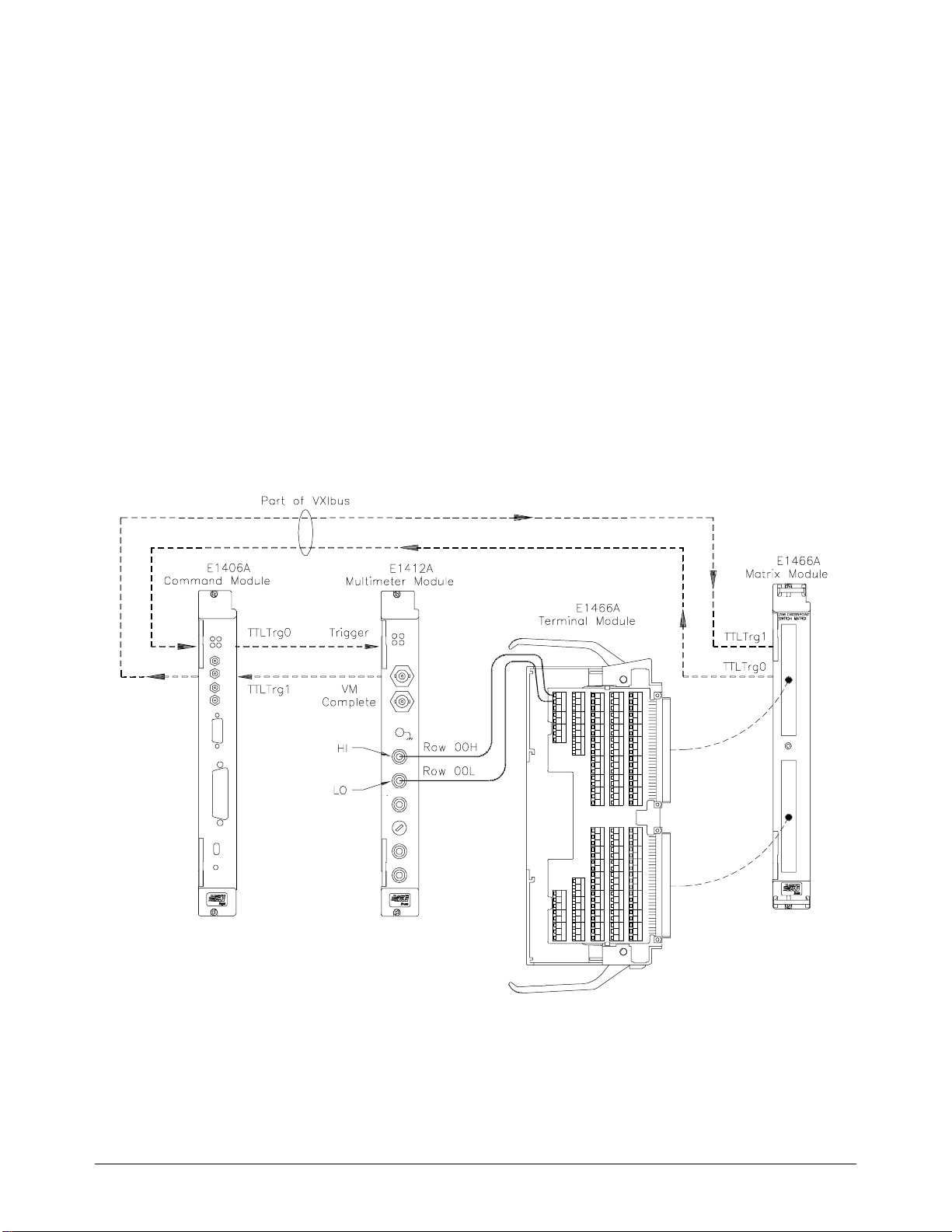
This example uses the command module’s TTL Trigger Bus Lines to
synchron i ze mat rix channel closures to a s y s tem mu ltim eter (Agilent
E1412A). For measurement synchronization:
• Agilent E1406A TTL Trigger Bu s Line 0 is used by the matr ix
module to trigger the multimeter to perform a measurement.
• Agilent E1406A TTL Trigger Bus Line 1 is used by the mul ti mete r
to advance the matrix scan.
These trigger bus li ne s a re not actual hardware connec ti ons. The triggering
is accomplished by the Agilent E1406A’s firmware. Row 00 (High and
Low) of an Agilent E1465A 16 x 16 Relay Matr i x Module is connect ed to
the voltme te r ’ s H igh and Low. The columns are then sc a nne d, switchi ng in
different DUTS (devi c es under te st). Fig ur e 3-1 shows how to connect th e
matrix module to the mult imeter module. The c onne c ti ons shown with
dotted lines ar e no t a ctua l ha rd war e connections. These connections
indicate how the firmware operates to accomplish the triggering.
Figure 3-1. Example: TTL Trigger Bus Scanning
48 Using the Matrix Chapter 3
Page 51

The following BAS I C progr a m se t s up the voltmete r (GP I B addr e ss 70903)
to scan making two-wire resistance measurements. The matrix is set to scan
row 00, columns 00 to 15 on an Agilent E1465A Ma tr ix Module:
10 ALLOCATE REAL Rdgs(1:16)
! Reset and clear the modules.
20 OUTPUT 70915; "*RST;*CLS"
30 OUTPUT 70903; "*RST;*CLS"
! VM Triggers on TTL Trigger line 0, VM pulses TTL Trigger line 1 on
! measurement complete. Set VM function to Resistance, range, NPLC
40 OUTPUT 70903; "ABORT;:TRIG:SOUR TTLTRG0"
50 OUTPUT 70903; "OUTP:TTLTRG1:STAT ON"
60 OUTPUT 70903; "CONF:RES AUTO,DEF"
70 OUTPUT 70903; "TRIG:DEL 0; COUN 16;:CAL:ZERO:AUTO ON"
! Check to see if VM ready; when ready, initialize trigger.
80 OUTPUT 70903; "*OPC?"
90 ENTER 70903; Check
100 OUTPUT 70903; "INIT"
! Set matrix to be triggered by TTL Trigger line 1.
110 OUTPUT 70915; "TRIG:SOUR TTLTRG1"
! Set up the matrix module: matrix pulses TTL Trigger line 0 on
! channel closed, scan list is R ow 0, Col um ns 0 to 15. Initiate scan.
120 OUTPUT 70915; "OUTPUT:TTLT0:STATE ON"
130 OUTPUT 70915; "SCAN (@10000:10015)"
140 OUTPUT 70915; "INIT"
! Enter and print readings.
.
150 OUTPUT 70903; "FETCH?"
160 ENTER 70903; Rdgs(*)
170 PRINT Rdgs(*)
180 END
Example: Sca nning
Channels with an
External Instrument
Using Trigger In
and Out
The following exa mpl e use s the Agilent E1406A Comma nd Module Trig In
and Trig Out port s to synchronize th e m atr ix module channel cl osures to an
external Agilent 3457A voltmeter. Figure 3-2 shows how t o co nne c t the
voltmeter to the command and m atr ix modules. Note that t h e com ma nd
module’s Trig In port connec ts to the volt me te r ’ s Complete por t, an d the
command module’s Trig Out port connects to the voltmeter’s External
Trigger port. The external voltmeter is at addres s 722.
Chapter 3 Using the Matrix 49
Page 52
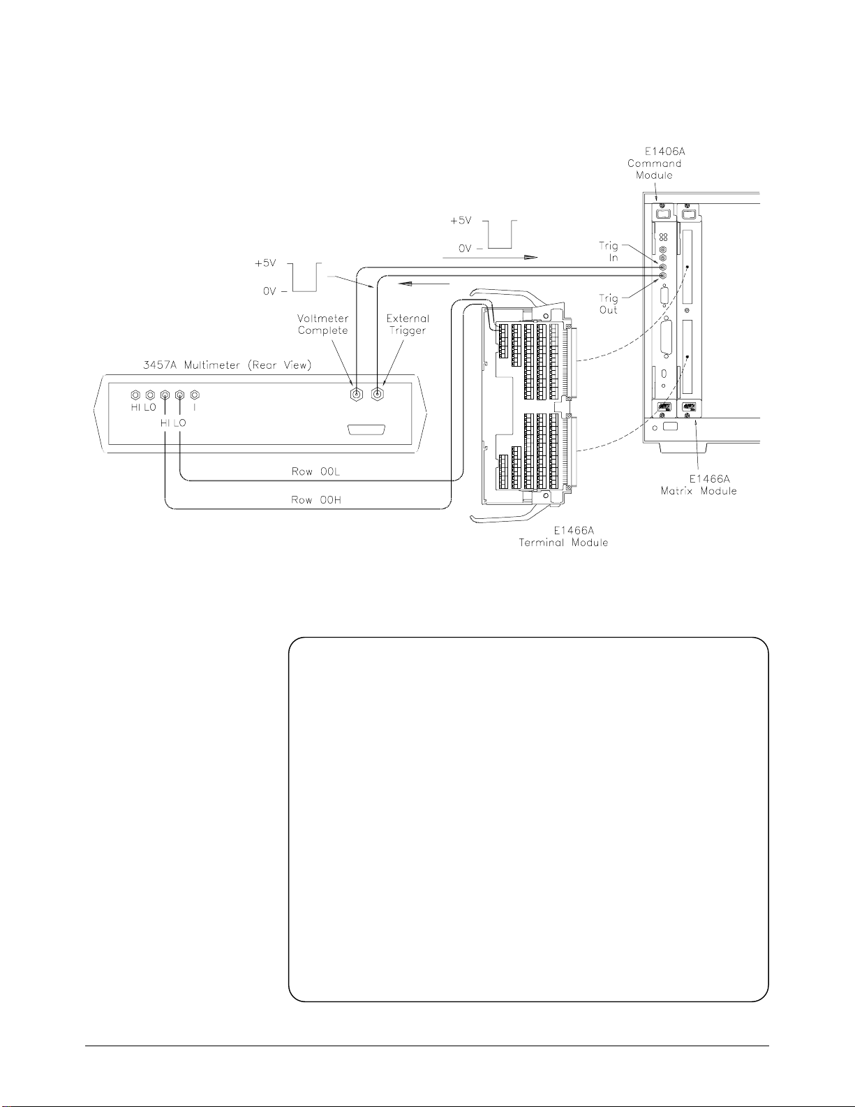
Figure 3-2 . Scanning with an External Vo ltmeter
! Set up voltmeter for external trigger, DCV measurements, memory
! first in first out storage.
10 OUTPUT 722; "TRIG EXT; DCV;MEM FIFO"
! Reset the matrix, enable the Agilent E1406A Trig Out port, se t tri gge r
! source to external trigger in g.
20 OUTPUT 70915; "*RST;*CLS"
30 OUTPUT 70915; "OUTP ON"
40 OUTPUT 70915; "TRIG:SOUR:EXT"
! Set matrix measurement mode, define chan ne l lis t, ini ti at e sc an.
50 OUTPUT 70915; "SCAN (@10000:10015)"
60 OUTPUT 70915; "INIT"
70 WAIT 2
80 FOR Channels = 1 to 16
90 ENTER 722;Results
100 PRINT Results
110 NEXT Channels
120 END
50 Using the Matrix Chapter 3
Page 53

Querying the Matrix Module
All query comm an ds e nd wit h a "?". These commands are used to
determine a sp ecific state of the module. The da ta is se nt to the outp ut
buffer where you can retrieve it into your computer. See Chapter 4 for more
information on these commands.
CLOSe? <channel_list> and OPEN? <channel_list> commands return
The
the current state of the specified channel. These commands return "1" if the
operation is tr ue , and " 0" if false. See Chapter 4,
[ROUTe:] CLOSe? c ommands for additional information on these
commands.
Note A maximum of 128 chan ne ls c a n be que rie d at one ti me . There f ore, if you
want to query more than 128 channels, you must enter the query data in two
separate commands.
The following e xa mpl e close s a range of ch an ne ls on the
Agilent E1467A 8 x 32 Matrix Module and queries for the results:
[ROUTe:]OPEN? an d
! Dimensions two string variables to 128 characte rs .
10 DIM Chan1$[128], Chan2$[128]
!Closes rows 00 through 07, co lumns 00 through 31.
20 OUTPUT 70915;"CLOS (@10000:10731)"
! Queries rows 00 through 03, c olu m ns 00 through 31 to see if the
! channels are closed.
30 OUTPUT 70915; "CLOS? (@10000:10331)"
! Enter the results of the first 128 c hannel closures.
40 ENTER 70915; Chan1$
! Queries rows 04 through 07, c olu m ns 00 through 31 to see if the
! channels are closed.
50 OUTPUT 70914; "CLOS? (@10400:10731)"
! Enter the results of the second 128 channel closur e s .
60 ENTER 70915; Chan2$
! Prints all the channels that are cl osed (should print 1’s).
70 PRINT "Channels closed";Chan1$, Chan2$
80 END
!
Chapter 3 Using the Matrix 51
Page 54

Using the Scan Complete Bit
You can use the Scan Complete Bit (bit 8) in the Operation Status Register
(command module) to determine when a scanning cycle completes (no other
bits in the register apply to the switchbox). Bit 8 ha s a decimal value o f 25 6
and you can read it di rectl y using the
STATus:OPERation[:EVENt]? co mman d in Chapter 4.
STAT:OPER? command. Refer to the
When enabled by the
STAT:OPER:ENAB 256 command, the Scan Complete
Bit will b e re por te d a s Bit 7 of the Status Registe r . Use the GPIB Seria l Poll
or the IEEE 488.2 Common comm and
When Bit 7 of the Status Register is enabled by the
*STB? to read the Status Register.
*SRE 128 Commo n
Command to asse r t an GPIB Service Request (SRQ) , you c an interrupt the
computer when the Scan Complete Bit is set, after the scanning cycle
complete s. T his allows the controller to do other oper a tions while the
scanning cycle is in progress.
The following e xa mple monitors b it 7 in the Status Registe r to de termine
when the scanning cycle is complete. The computer used in this example is
an HP 9000 Series 200/300 computer run ning BASIC as the programm ing
language. The computer interfaces with an Agilent E1406A Command
Module over GPIB. The GPIB select code is 7, the GPIB pri mar y ad dres s is
09, and the GPIB seco nda r y ad dres s is 15.
! Reset and Clear the Matrix.
10 OUTPUT 70915;"*RST; *CLS"
! Enable Scan Complete Bi t.
20 OUTPUT 70915; "STATUS:OPER:ENABLE 256"
! Set the matrix up for continuous triggering.
30 OUTPUT 70915; "TRIG:SOUR IMM"
! Select channels to scan.
40 OUTPUT 70915; "SCAN (@10000:10015)"
! Wait for op eratio n comp lete.
50 OUTPUT 70915; "*OPC?"
60 ENTER 70915; A$
70 PRINT "*OPC? = ";A$
! Query the contents in the op eration status registe r.
80 OUTPUT 70915; "STAT:OPER:ENAB?"
90 ENTER 70915; A$
100 PRINT "STAT:OPER:ENAB? = ";A$
Continued on ne xt page .
52 Using the Matrix Chapter 3
Page 55

! Query the contents of the status byte register.
110 OUTPUT 70915; "*STB?"
120 ENTER 70915; A$
130 PRINT "Switch Status = ";A$
! Start scan cycle.
140 OUTPUT 70915; "INIT"
! Initialize the value of the counter.
150 I = 0
! Stay in loop until some value is ret ur ne d from th e SP O LL (70915)
! command.
160 WHILE (I=0)
170 I = SPOLL(70915)
180 PRINT "Waiting for scan to complete: SPOLL = ";I
190 END WHILE
200 I = SPOLL(70915)
210 PRINT "Scan complete: spoll = ";I
220 END
Recalling and Saving States
This section c ont ai ns information about saving and reca ll ing current matrix
module states.
Storing States The *SAV <numeric_state> command stores the current state of the matrix
channels. Up to 10 states can be stored by specifying the
as an integer 0 th ro ugh 9. The fo llowing states are store d:
<numeric_state>
• Channel relay states (open or closed)
• ARM:COUNt
• TRIGger:SOURce
• OUTPut[:STATe]
• INITiate:CONTinuous
Recalling States The *RCL <numeric_state> command recalls the specified previously stored
state. If the specified
configures to it s powe r - on/ rese t states (refer to Tabl e 3-2). The following
program shows how to save and recall matrix switch states:
! Dimensions a string variable A$ to 30 character s.
10 DIM A$[30]
! Close channels on the matrix module.
20 OUTPUT 70915; "CLOS (@10000:10015)
<numeric_state> does not e xist, the mat r ix m odule
Continued on ne xt page .
Chapter 3 Using the Matrix 53
Page 56

! Save as numeric state 5.
30 OUTPUT 70915; "*SAV 5"
! Reset and clear th e module.
40 OUTPUT 70915; "*RST; *CLS"
! Query to see wh at c hannels are closed.
50 OUTPUT 70915; "CLOS? (@10000:10020)"
60 ENTER 70915;A$
70 PRINT "Channels Closed:";A$
! Recall numeric state 5.
80 OUTPUT 70915; "*RCL 5"
! Chec k to see i f the recalled ch annels a r e closed.
90 OUTPUT 70915; "CLOS? (@10000:10200)"
100 ENTER 70915; A$
! Prints 1s for the fir st 16 c hannels that are closed and 0s for the
! remainin g 5 chan n els.
110 PRINT "Channels Closed:";A$
120 END
Detecting Error Conditions
The SYSTem:ERRor? query requests a value from instrument’s error
register. This register contains a n integer in the ra nge [-32 768 to 32767].
The response tak es the fo llowing form:
<err_number>,<err_message>
where <err_number> is the va lue of the inst ru me nt’s error, and
<err_message> is a sh or t de sc r ipt ion of the error.
The following pr ogr a ms at te mpt an illega l c ha nne l cl osur e fo r the Ag il en t
E1466A (4 X 64 Matrix) and poll for th e erro r m es sag e :
BASIC
10 DIM Err_num$[256] ! Dimensions a stri ng v ari able,
20 OUTPUT 70915; "CLOS (@10500)" ! Try to close an illegal channel.
30 OUTPUT 70915; "SYST:ERR?" ! Check for a sy ste m e rror.
40 ENTER 70915; Err_num$ ! Enter the errors into
50 PRINT Err_num$ ! Prints erro r +2001, "Invalid
60 END
Err_num$ for 256 ch arac ters.
Err_num$.
channel number".
54 Using the Matrix Chapter 3
Page 57

TURBO C #include <stdio.h>
#include <chpib.h>
#define ISC 7L
#define MATRIX 7091 5L
#define TASK1 "CLOSE (@10500)"
#define TASK2 "SYST:ERR?" /*Command for system error*/
main()
{
char into[257];
int length = 256;
error_handl er (IOTIMEOUT (7L,5. 0), "TIMEOUT ");
error_handler (IOOUTPUTS (MATRIX, TASK1, 15), "OUTPUT command");
error_handler (IOOUTPUTS (MATRIX, TASK2, 9), "OUTPUT command");
/*Include file for GPIB*/
/*Matrix default address*/
/*Command for ille gal switch closure*/
/*Output commands to matrix*/
/*Enter from matrix*/
error_handler (IOENTERS (MATRIX, into, &length), "ENTER command");
printf("Now let’s print the errors: %s",into);
return;
}
int error_handler (int error , cha r *routine)
{
char ch;
if (error != NOERR)
{
printf ("\n Error %d %s \n", error, errstr(error));
printf (" in call to GP IB f uncti on % s \n\n", routine);
printf ("Press ’Enter’ to exit: ");
scanf ("%c", &c h);
exit(0);
}
return 0;
}
If no error occurs, th e swi tchbox responds wit h 0,"No error". If there has
been more than one error, the instrument will respond with the firs t one in
its error queue. Subs eq ue nt queries continue to r e ad the error que ue unt il it
is empty. Th e ma ximum <err_message> string length is 255 characte rs.
Chapter 3 Using the Matrix 55
Page 58

Synchronizing the Matrix Module
The following exa mple shows how to synchro niz e a mat rix module with
measurement instruments. In thi s example, the m at rix module swit ch es a
signal to a multimeter. The program verifies that the channel is closed
before the multimeter begins its measurement.
10 OUTPUT 70915; "*RST" ! Reset the module.
20 OUTPUT 70915; "CLOS (@10012)" ! Close a c hanne l.
30 OUTPUT 70915; "*OPC?" ! Wait for operation complete.
40 ENTER 70915; Opc_value
50 OUTPUT 70915; "CLOS? (@10012)" ! Test that the channel is closed.
60 ENTER 70915;A
70 IF A=1 THEN
80 OUTPUT 70903;"MEAS:VOLT:DC?"
90 ENTER 70903; Meas_value ! Print th e me asured value .
100 PRINT Meas_value
110 ELSE
PRINT "CHANNEL DID NOT CLOSE"
120 END IF
130 END
! When channel is closed,
measure the voltage.
56 Using the Matrix Chapter 3
Page 59

Understanding the Relay Matrix
This section provides additi ona l de t ai ls about the Agilen t E1465/66/67A
relay matri ces. It ex pla ins the intern al c onf iguration so yo u can be t te r
understand how ea ch ma tr ix operates.
Advantages of
Latching Relays
Increased System
Throughput
There are several adva nt a ge s to using the Agile nt E1465A/E1466A/ E1467A
latching rela ys. First, wit h 256 relays on the de nse ma trix relay module,
latching relays prevent excessive current dr awn from the power supply if the
user closes too many relays accidentally. Second, energy is saved since
power is not cont inually appli ed to ke e p a l at c hing relay closed. Thir d, by
not continually applying power , the rel ay coi l does not heat up. This is
important be c ause the two meta l c ontacts inside the relay, in ef fec t, f or m a
thermocoupl e . Thu s, te mpe ra tur e diff e renc e s on t he rela y c ont a ct s c au se
thermal EMF (ele c tromotive force) to be gene r at e d. Also, the li f e of the
latching relay is usually longer tha n the nonlatching relay because of the
power that must be con ti nua lly applied to close a nonlat ch ing relay.
The main dis ad va n ta ge of la tc hing relays i s tha t the relay state is un c ha nge d
at power-on, power-o ff, or follo w ing a reset. Therefore, the device’s
firmware must en sure tha t a ll rel ay s are ope n following these conditions.
In conventional switch mod u le de si gns, the module int err upts the central
processing unit (CPU) each time a relay is opened or closed. In the design
of the Agilent E 1465A/E1466A/E14 67A ma trix relay module s, the CPU is
interrupte d one time after al l r el a ys in the specified c hannel list have be en
opened or closed . Thu s, system throughpu t spe e d is increased.
The following de sc ribe s the relay module fun ct io ns ( se e Figure 3-3):
• A command is se nt to the relay modul e and stored in the FIFO
memory.
• O nce the data is in mem o r y, the VME Ti ming PAL (pr ogram mable
array logic) as sert s DTAC K*. This signals the CPU on the relay
module’s com ma nde r tha t it is now free to servi ce other tasks.
• The VME Timing PAL signals the FIFO Interface PAL to execute
the command. During execution, the Data Bus FIFO EMPTY* flag
signals the FIFO Interface PAL to read the Data Bus and Address
Bus FIFO and genera te 7-ms pulses to activa te the relays. Only one
7-ms pulse is required per relay ba nk ( up t o 16 rel a ys) .
• The FIFO Int er face PAL reads the Data Bus and A d dress Bu s FI FO
until the EMPTY* flag signals the FIFO Interface PAL the FIFO
memory is empty.
Chapter 3 Using the Matrix 57
Page 60
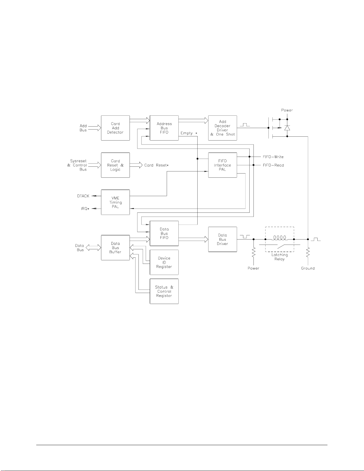
• When the FIFO is empty, the FIFO Interface PAL signals the VME
Timing PAL which asse r ts I RQ*. This in te r ru pts the comm an d
module CPU afte r the la st re la y ha s be e n activated.
Because the relay module asserts IRQ* after the last relay is activated, the
CPU is not continually interrupt e d; thus, system t hroughput is enhance d.
Figure 3-3. Matrix Module Block Diagram
58 Using the Matrix Chapter 3
Page 61

Relay Matrix Command Reference
Using This Chapter
This chapter sum ma r iz e s SC PI (Sta ndard Commands f or Progr a mm a ble
Instrument s) comma nds and IEEE 488.2 Com mon (*) commands used in
this man ua l.
See the Agilent E1406 Command Modu le Use r’ s Manual for additional
information on SCPI and common commands. Chapter contents are as
follows:
Chapter 4
• Command Types . . . . . . . . . . . . . . . . . . . . . . . . . . . . . . . . . . Page 59
• SCPI Command Format. . . . . . . . . . . . . . . . . . . . . . . . . . . . . Page 60
• SCPI Command Reference . . . . . . . . . . . . . . . . . . . . . . . . . . Page 63
• IEEE 488.2 Common Commands . . . . . . . . . . . . . . . . . . . . . Page 88
• SCPI Command Quick Reference . . . . . . . . . . . . . . . . . . . . . Page 89
Command Types
Common
Command Format
Commands are sepa r at e d int o two types: IEEE 488 .2 Com mon commands
and SCPI commands. Each of these types of c ommands are discussed in the
following sec ti ons.
The IEEE 488.2 standard defines the Common commands that perform
functions like reset, self-test, status byte query, etc. Common commands are
four or five characters in length, a lways begin with the asterisk character (
and may include one or mor e parameters. The com mand keyword is separate d
from the first parameter by a space character. Some examples of Common
commands are shown below:
*RST *ESR 32 *STB?
*),
Chapter 4 Relay Matrix Command Reference 59
Page 62

SCPI Command Format
The SCPI commands perform functions like closing switches, making
measurements, and querying instru me nt st ates or r etrieving data. A subsystem
command structure is a hierarchical structure that usually consists of a top-level
(or root) command, one or more l ower-le vel commands, a nd their parameters.
The following example shows part of a typical subsystem:
[ROUTe:]
CLOSe <
SCAN <
channel_list>
channel_list>
Note There is a space betwee n the se c ond-level comman d (for e xa mpl e , CLOSe)
Command
Separator
Abbreviated
Commands
ROUTe:
commands.
and th e
A colon (:) always sep arate s one comm a nd from th e ne xt lower-le vel
command as shown below:
Colons separate the root command from the second-level command
[ROUTe:]SCAN).
(
The command syntax shows most commands as a mixture of upper- and
lowercase letters. The uppercas e l et ter s indicate th e abbre viated spelling for
the command. For shorter program lin es , send the abbrevia te d f orm, a nd f or
better program readability, send the entire command. The instrument will
accept either the abbreviate d form or the entire comma nd.
is the root com mand and CLOSe and SCAN are seco nd-lev el
<channel_list>.
[ROUTe:]SCAN
For example, if the command syntax shows
TRIGGER are both acceptable forms. Other forms of TRIGger, such as
TRIGG or TRIGGE will generate an error. You may use upper- or lower-
case letters. Therefore,
TRIGGER, trigger, and TrIgGeR are all acceptable.
TRIGger, the n TRIG and
60 Relay Matrix Command Reference Chapter 4
Page 63

Implied Commands Implied com ma nds are those which appe ar in squa r e brac ke ts ( [ ] ) in the
command syntax. (Note that the brackets are not part of the command and
are not sent to the instrument.) You can se nd a second-level co mm an d but
you do not need t o se nd the preceding implied command. In this case, th e
instrument assumes you intend to use the implied command and it responds
as if you had sent it. Examine th e [
[ROUTe:]
ROUTe:] subsystem which follows:
CLOSe? <channel_list>
The root command [ROUTe:] is an implied command. To make a query
about a channel ’s prese nt status, you ca n se nd e it he r of th e following
command statements:
ROUT:CLOSe? <channel_list> or CLOSe? <channel_list>
Parameters Parameter Types. The following table contains explanations and examples
of the paramete r type s you might see la t er in this chapte r .
Parameter Type Explanations and Examples
Numeric
Boolean
Discrete
Accepts all com m only used decimal repres entat i ons of num be rs
including opti onal signs, decimal point s, and sci entific notation.
123, 1.23E2, –123, –1.23E2, .123, 1. 23E – 2, 1.2 3000E–01.
Special case s in clude M I N imum , MAXim um , and I N Fini ty .
Represents a single binary condition t hat is either true or false.
ON, OFF, 1, 0
Selects from a fini te set of val ues . The se par am et er s use
mnemonics to represent each valid setting.
An example is TRIG ger :SOU Rce <
be BUS, EXT, HOLD, or IMM.
source> where <source> can
Optional Parameters. Parameters shown within square br ackets ( [ ] ) a re
optional parameters. (Note tha t the brackets are not pa rt of the c omma nd a nd
are not sent to the instrument.) If you do not specify a value for an optional
parameter, the instrument c hooses a default va lue. For example, consider the
ARM:COUNt? [MIN | MAX] command. If you send the command without
specifying a parameter, the current number of scanning cycles is returned. If
you send the
If you send the
MIN parameter, the c omma nd r eturns the minimum avai labl e (1).
MAX parameter, the command returns the maximum available
(32,767). Be sure to place a space between the command and the parameter.
Chapter 4 Relay Matrix Command Reference 61
Page 64

Linking Commands Linking IEEE 488.2 Common Commands with SCPI Commands: Use a
semicolon (;) between the commands. For example:
*RST;OUTP ON or TRIG:SOUR HOLD;*RST
Linking Multiple SC P I Commands. Use both a se micolon (;) and a colon
(:) between the commands. For example:
ARM:COUN 1;:TRIG:SOUR EXT
62 Relay Matrix Command Reference Chapter 4
Page 65

SCPI Command Reference
This section de sc ribe s the Standard Comm a nds f or Progr a mm a ble
Instruments (SCPI) commands for the relay matrix. Commands are listed
alphabetic a ll y by subsystem and within each subsystem.
ABORt
The ABORt command subsystem stops a scan in progress when the scan is
enabled via the interface and the trigger source is
TRIGger:SOURce HOLD.
Subsystem Syntax ABORt
TRIGger:SOURce BUS or
Comments
ABORt Actions: ABORt aborts the sca n a n d invali d a tes the current
•
channel list .
• Stopping Scan Enabled via Interface: When a scan is enabled by
way of an interface, an interface clear
used to stop the scan. When the scan is enabled via the interface and
TRIG:SOUR BU S or HO LD is se t, you can use ABORt to stop the
scan.
• Restarting a Scan: Use the INIT command to restart the scan.
• Related Commands: ARM, INITiate:CONTinuous, [ROUTe:]SCAN,
TRIGger
Example Stopping a Scan with ABORt
This example stop s a (c ont inuous) scan in prog ress.
TRIG:SOUR BU S *TRG command is trigger
INIT:CON T ON Set continuous scanning.
SCAN (@10000:10003) Scan channels 00-03.
INIT Start scan, close channel 00.
.
.
ABOR
command (CLEAR 7) can be
source.
Abort scan in progress.
Chapter 4 Relay Matrix Command Reference 63
Page 66

ARM
Subsystem Syntax ARM
The ARM subsystem selects the number of scanning cycles (1 to 32767) for
each
INITiate command.
:COUNt <
:COUN t? [MIN | MAX ]
number> MIN | MAX
:COUNt ARM:COUNt <number> allows scanning cycles to occur a multiple of times
INITiate command when INITi a te :C ON Ti n uou s O FF | 0 is
Parameters
(1 to 32767) with one
MIN sets 1 cyc le an d MAX sets 32,767 cycles.
set.
Parameter Name Parameter Type Range of Values
<
number> numeric 1 – 32767 | MIN | MAX
Comments
• Number of Scans: Use only num e ric value s be twee n 1 a nd 32767
for the number of scanning cycles.
• Related Commands: ABORt, INITiate[:IMMediate]
• *RST Condition: ARM:COUNt 1
Example Setting Ten Scanning Cycles
This example sets a relay matrix for 10 scans of ch an ne ls 10000 through
10003. When the sc a n se que nce com pletes, channels 10000 through 10 003
are closed.
ARM:COUN 10 10 scans per INIT command.
SCAN (@10000:10003) Scan channels 10000-10003.
INIT Start scan, close channel
10000.
64 Relay Matrix Command Reference Chapter 4
Page 67

:COUNt? ARM:COUNt? [MIN | MAX] returns the current number of scanning cycles
ARM:COUNt. The current number of scan cycles is returned when
set by
MIN or MAX is not specified. Wi th MIN or MAX as a parameter, MIN returns
MAX returns 32767.
1 and
Parameters
Parameter Name Parameter Type Range of Values
MIN | MAX numeric MIN = 1, MAX =32767
Comments
•
Related Commands: INITiate[:IMMediate]
Example Query Number of Scans
This example set s a sw it ch box f or 10 sc anning cycles of channe ls 10000
through 10003 a nd queries the numbe r of sca n cy cle s se t. The
command retur ns 10.
ARM:COUN 10 Set 10 scans per INIT command.
ARM:COUN? Query number of scans.
ARM:COUN?
Chapter 4 Relay Matrix Command Reference 65
Page 68

DISPlay
The DISPlay subsystem monitors the ch an ne l state of the sel e ct e d module in
a switchbox. Thi s subsystem operate s wit h an Agilent E1406A when a
terminal is connected.
Subsystem Syntax DISPlay
:MONitor
[:STATe] <
:CARD <
:MONitor[:STATe] DISP lay:MONitor[:STATe] <boolean> turn s the monitor mod e on or off .
Parameters
Parameter Name Parameter Type Range of Values
STATe boolean ON | OFF | 1 | 0
boolean>
number>|AUTO
Comments
• Monitoring Switchbox Channels: DISPlay:MON it or[STATe] ON or
DISPlay:MONitor[:STATe] 1 turns the monitor mode on to show the
channel state of the se le cted m odule.
DISPlay:MONitor[:STATe] 0 turns the channel monitor off.
• S e l ecti ng the Mod ul e to be Monit or ed: Use the
DISPlay:MONitor:CARD <number> AUTO command to s elect the
module.
• Monitor Mode with an Agilent E1466A/67A/ 68A: When monitor
mode is turn on, a hexa de c im al number representi ng the channels
closed will be displayed at th e bo ttom of the term ina l . Fo r exa mple,
an Agilent E1 466A wi th r ow 0, co lumns 0-3 closed wil l look like to
following:
R0: 0000 0000 0000 000F R1: 0000 0000 0000 0000 R2: 0000 0000 . . . etc.
Where 000F
closures for columns 0-3. If 000C
(1100) would be clos ed.
represents colum ns 0- 15. F (1111) represents cha nne l s
h
• *RST Condition: DISPlay:MONitor[:STATe] OFF | 0
Example Enabling the Monitor Mode
DISPlay:MONitor[:STATe] OFF or
was listed instead, then columns 2 and 3
h
DISP:MON:CARD 2 Selects module #2 in a
switchbox.
DISP:MON 1 Turns monit or mode O N.
66 Relay Matrix Command Reference Chapter 4
Page 69

:MONitor:CARD DISPlay:MONitor:CARD <number> | AUTO selects the module in a
switchbox to be monitored.
Parameters
Parameter Name Parameter Type Range of Values
<number>| AUTO numeric 1 - 99
Comments
• Selecting a Specific Module to be Monito re d: Use the
DISPlay:MONitor:CARD command to send the card number for the
switchbox to be monitored.
• Selecting the Present Module to be Monitored: Use the
DISPlay:MONitor:CARD AUTO command to sel e ct the la st module
addressed by a swit c hing command (for e xa mpl e ,
• *RST Conditions: DISPlay:MONitor:CARD AUTO
Example Select Module #2 in a Sw itchbox for M o nitoring
DISP:MON:CARD 2 Selects module #2 in a
[ROUTe:]CLOSe ).
switchbox.
Chapter 4 Relay Matrix Command Reference 67
Page 70

INITiate
Subsystem Syntax INITiate
:CONTinuous INITiat e :CONt in uous <mode> enables or disabl e s co ntinuous scanni ng
Parameters
The INITiate command subsystem selec ts c ont inuous scanning cycles and
starts the scanning cycle.
:CONTinuous <
:CONTinuous?
[:IMMediate]
cycles for the matrix.
Parameter Name Parameter Type Range of Values
<mode> boolean ON | OFF | 1 | 0
mode>
Comments
• C o ntinuou s Sca nning Operation: Continuous scanning is enabled
with the
command. Sending the INITiate[:IMMediate] command closes the
first channel in the channel list. Each trigger from a trigger source
specified by the
through the channel list. A trigger at the end of th e cha nne l list
closes the first channel in the channel list and the scan cycle repeats.
INITiate:CONTinuous ON or INITiate:CONTinuous 1
TRIGger:SOURce comm and ad v ances the scan
• Non-Contin uo us Scanning Ope ratio n: Non- co nti nuous scanning
is enabled with the
INITiate:CONTinuous 0 command. Sending the INITiate[:IMMediate]
command closes the first channel in the channel list. Each trigger
from a trigger source selected by the
advances the sca n thr ough the channel lis t. At the end of the
scanning cycle, the last channel in the channel list is opened.
• Stopping Con tinuous Sc a n: See the ABORt command.
• Related Commands: ABORt, ARM:COUNt, TRIGger,
TRIGger:SOURce
• *RST Condition: INITiate:CONTinuous OFF
Example Enabli ng C o ntinuou s Sc a nning
INITiate:CONTinuous OFF or
TRIGger:SOURce command
This example enables continuous scanning of channels 10000 through 10003 of
a single module. Since
example uses an interface clear command (such as
INIT:CON T ON Enable cont inuous scannin g.
SCAN (@10000:10003) Defines channel list.
INIT Start scan cycle, cl ose c hannel
TRIGger:SOURce IMMediate (default) i s set , t he
CLEAR) to stop the scan.
10000.
68 Relay Matrix Command Reference Chapter 4
Page 71

:CONTinuous? INITiate:CONTinuous? queries the scanni ng st a te . Wi th continuous
scanning ena ble d, the command retur ns 1 (On). With continuous scanning
disabled, the command retur ns 0 (Off).
Example Query Continuous Scanning State
This example enables continuo us sc a nning of a matrix modul e and que rie s
the state. Since continuous sca nning is enabled,
INIT:CON T ON Enable cont inuous scannin g.
INIT:CONT? Query continuo us sc anning
INIT:CONT? returns 1.
state.
[:IMMediate] INITiate[:IMMediate] starts the sc an ning process and cl ose s the first
channel in the channel list. Successive triggers from the source selected by
TRIGger:SOURce command advanc e the sc an through the channel list.
the
Comments • Starting the Scanning Cycle: The INITiate[:IMMediate] co mman d
starts scanning by closing the fir st c ha nne l in the channel list. Each
trigger received advances the scan to the next channel in the channel
list. An invalid channel list definition c au se s an err or (see
[ROUTe:]SCAN ).
• Stopping Scanning C y cles: See the ABORt command.
Example Enabling a Sin gle Scan
This example enables a single scan of c ha nne ls 10000 through 1000 3 of a
matrix mo dule. The trig ge r so ur ce to advance the scan is imm e dia te
(internal) tr iggering set wi th (d e fault)
SCAN (@10000:10003) Scan channels 10000-10003.
INIT Begin scan, close channels
TRIGger:SOURce IMMediate.
10000 (use immedi ate
triggering).
Chapter 4 Relay Matrix Command Reference 69
Page 72

OUTPut
The OUTPut command subsyste m e na ble s or disables the dif f ere nt tr igger
lines of the Agi lent E1406A Command Mo dule.
OUTPut
:EXTernal
[:STATe] <
[:STATe]?
[:STATe] <
[:STATe]?
:TTLTrg<
[:STATe] <
[:STATe]?
:EXTernal[:STATe] OUTPut:EXTernal[:STATe] <mode> enables or disables the Trig Out port
on the Agil en t E1406A Comm an d Module to outpu t a tr igger when a
channel is close d during a scan.
disables the p ort.
Parameters
mode>
mode>
n> (:TTLTrg0 through :TTLTrg7)
mode>
ON | 1 enabl es th e p ort and OFF | 0
Comments
Example
Parameter Name Parameter Type Range of Values
<mode> boolean ON | OFF | 1 | 0
• Enabling Trig Ou t Port: When enabled, a pulse is output from the
Trig Out port after each scanned switchbox channel is closed. If
disabled, a pulse is not outp ut f r om t h e por t aft e r cha nne l closures.
The output pul se is a +5V ne ga ti ve -g oing pulse.
• Trig Out Port Shared by Switchboxe s: When enabled, the Trig
Out port is pulsed by the switchbox each time a scanned channel is
closed. To disa bl e t he output for a speci fic module, send the
OUTPut:EXTernal[:STATe] OFF or 0 command for that module.
• One Output Selected at a Time: Only one output (TTLTrg or
EXTernal) can be enabled at one t im e. Ena bling a different out put
source will automatically disable the active output.
• Related Commands: [ROUTe:]SCAN, TRIGger:SOURce
• *RST Condition: OUTPut:EXTernal[:STATe] OFF (port disabled)
OUTP:EXT ON En able Trig Out port to output
pulse after ea ch sca nne d
channel is clo se d.
70 Relay Matrix Command Reference Chapter 4
Page 73

:EXTernal[:STATe]? OUTPut:EXTernal[:STATe]? queries the present state of the Trig Out port.
The command returns 1 if the port is enab le d or 0 if the port is disa bl ed.
Example Query Trig Out Port Enable State
This example enables the Trig Out port and queries the enable state. The
OUTPut:EXTernal[:STATe]? command returns 1 since the port is enabled.
OUTP:EXT ON En able Trig Ou t port.
OUTP:EXT ? Query port enable state.
[:STATe] OUTPut[:STAT e ] <mode> enables or disables the Tr ig Out por t on the
Parameters
Agilent E1406A Command Module.
port and
functions the sa me as the
Parameter Name Parameter Type Range of Values
OUTPut[:S TATe] OFF | 0 disables the port. This command
OUTPut:EXTernal[:STATe] command.
<mode> boolean ON | OFF | 1 | 0
OUTPut[:ST AT e ] ON | 1 enables t he
Comments
•
*RST Condition: OUTPut[:STATe ] OFF (por t disabled)
Example Enabling T rig Out Port
OUTP ON Enable Tr ig O ut port to output
pulse after ea ch sca nne d
channel is clo se d.
[:STATe]? OUTPut[:STATe]? queries the present state of the Trig Out port. The
command returns 1 if the port is enabled or 0 if th e po rt is disabled. Thi s
command func ti ons the same as the
Example Query Trig Out Port Enable State
This example enables the Trig Out port and queries the enable state. The
OUTPut[:STATe]? command returns 1 since the port is enabled.
OUTP ON Enable Trig Out port .
OUTP ? Query port enabl e state.
OUTPut:EXTernal[:STATe]? command.
Chapter 4 Relay Matrix Command Reference 71
Page 74

:TTLTrg[:STATe] OUTPut:TTLTrg<n>[:STATe] <mode> selects and enables which TTL
Trigger bus li ne (0 - 7) will output a trigger when a cha nne l is closed during
a scan.
disables the spe ci f ie d bus line.
OFF | 0 disables the spe c ifie d bus line.
Parameters
<n> specifies the TTL Trigger bus line ( 0 to 7). <mode> enables or
ON | 1 enables the specified bus line, and
Parameter Name Parameter Type Range of Values
Comments
<n>
<mode>
• Enabling TTL Trigger Bu s: When e na bled, a pulse is output from
the select ed T TL T r igger bus line (0 - 7) afte r eac h c hannel in the
switchbox is closed. If disabled , a pulse is not output. The ou tput is
a negative going pulse.
numeric
boolean
• One Output Selected at a Time: Only one output (TTLTrg or
EXTernal) can be enabled at one t im e. Ena bling a different out put
source will automatically disable the active output.
• Related Commands: [ROUTe:]SCAN, TRIGger:SOURce,
OUTPut:TTLTrg<n>[:STATe]?
• *RST Condition: OUTP:TTLT<n>:STAT 0
Example Enabl ing TTLT Trig g er Bus Line 7
OUTP:TTLT7:STAT 1 Enable TTL Trigge r bus l ine 7
0 to 7
ON | OFF | 1 | 0
to output pulse after e ac h
scanned channe l is closed.
:TTLTrg[:STATe]? OUTPut:TTLTrg<n>[:STATe]? quer ies th e present state of the s p ecifi ed
TTL trigger bus line. The command returns 1 if the specified bus line is
enabled, or 0 if the specifie d bus l ine is disabled.
Example Query TTL Trigger Bus Line Enable State
This example enable s TTL Tri gge r bus li ne 7 an d que ries th e enable state.
OUTPut:TTLTrg<n>[:STATe]? comman d returns 1 since the port is
The
enabled.
OUTP:TTLT7:STAT 1 Enable TTL Trigger bus line 7.
OUTP:TTL7? Query bus enable state.
72 Relay Matrix Command Reference Chapter 4
Page 75

[ROUTe:]
Subsystem Syntax [ROUTe:]
The [ROUTe:] command subsyste m c ontrols switching a nd sc a nning
operations f or rel ay matrix modu le s.
CLOSe <
CLOSe? <
OPEN <
OPEN? <
SCAN <
channel_list>
channel_list>
channel_list>
channel_list>
channel_list>
Note There must be a space between the second-level command
(for example,
CLOSe ) and the <channel_list>.
CLOSe [ROUTe:]CLOSe <channel_list> closes the relay matrix channel s spe cified by
channel_list. channel_ list has the form (
number (01-99),
rr = matrix row number, a nd cc = matrix colum n number.
@ssrrcc) wher e ss = matrix card
Parameters
Comments
Paramete r Name Parameter Type Ra n ge of Val u es
<channel_list>
numeric
Agilent E1465A
rr:00 - 15
cc:00 - 15
Agilent E1466A
rr:00 - 03
cc:00 - 63
Agilent E1467A
rr:00 - 07
cc:00 - 31
• Closing Channels:
To close
– a single channel, use [ROUTe:]CLOSe (@ssrrcc) ;
– multiple ch annels, use [ROUTe:]CLOSe (@ssrrcc,ssrrcc,...) ;
– sequ ential channels , use [RO U T e:] CL OS e (@ss rrcc:ssrrcc) ;
– groups of sequent ia l c ha nne l s, use
[ROUTe:]CL O Se (@ssrrcc:ssrrcc, ssr rcc: ssrrcc) ;
– or any combinat ion.
Closure order for multiple channels with a single comman d is not
guaranteed.
• Related Commands: [ROUTe:]OPEN, [ROUTe:]CLOSe?
• *RST Condition: All channels open
Chapter 4 Relay Matrix Command Reference 73
Page 76

Example Closing Ma t r ix Channels
This example closes channels 10100 and 20013 of a two-module switchbox
(card numbers 01 and 02).
CLOS (@10100,20013) Closes row 01, column 00 of
card #1 and row 00, co lumn 13
of card #2.
CLOSe? [ROUTe:] CLOSe? <channel_list> returns the current state of the
channel(s) que rie d. ch anne l_list has the form
[ROUTe:]CLOSe for def i nit i o n). T h e command returns 1 if channel(s) are
closed or returns 0 if channel(s) are ope n.
(@ssrrcc) (see
Comments
•
Query is Software Readba ck: The [ROUTe:]CLOSe? command
returns the current softwar e state of the channe l(s) specified. It does
not account for relay hardware failures.
Note A maximum of 128 chan ne ls c a n be que rie d at one ti me . There f ore, if you
want to query more than 128 channels, you must enter the query data in two
separate commands.
Example Query Channel Closure
This example closes channels 10100 and 20013 of a two-module switchbox
and queries channel closure. Since the channels are programmed to be
closed 1,1 is returned as a string.
CLOS (@10100,20013) Closes row 01, column 00 of
card #1, and column 13 of card
#2.
CLOS? (@10100,20013) Query channel closure.
74 Relay Matrix Command Reference Chapter 4
Page 77

OPEN [ROUTe :] OP EN <channel_list> opens the relay matrix channels specifie d
by channel_list. channel_list has the form
card number (01-99) ,
rr = matrix row number, and cc = mat ri x c olumn
number.
Parameters
Parameter Name Parameter Type Range of Values
<
channel_list> numeric Agilent E1465A
Comments • Opening Channel s:
(@ssrrcc) where ss = matrix
rr: 00 - 15
cc: 00 - 15
Agilent E1466A
rr: 00 - 03
cc: 00 - 63
Agilent E1467A
rr: 00 - 07
cc: 00 - 31
To open
– a single cha nne l, use [R OUTe:]OPEN (@ssrrc c) ;
– multiple ch annels, use [ROUTe :] OPEN (@s s rr cc,ssrr cc,... ) ;
– sequ ential channels , use [R OUTe:]OPEN (@ssrrc c:ssrrc c) ;
– groups of sequent ia l c ha nne l s, use
[ROUTe:]OPEN (@ssrrcc:ssrrcc,ssrrcc:ssrrcc) ;
– or any combinat ion.
Opening order for multiple channels with a sing le command is not
guaranteed.
• Related Commands: [ROUTe:]CLOSe, [ROUTe:]OPEN?
• *RST Condition: All channels open
Example Opening Channels
This example opens channels 10100 and 20013 of a two-module switchbox
(card numbers 01 and 02).
OPEN (@10100,20013) Open c hannels 10100 and
20013.
Chapter 4 Relay Matrix Command Reference 75
Page 78

OPEN? [ROUTe:]O PEN ? <channel_list> returns the current state of the channel(s)
queried. channe l_list has the form
definition). The command returns 1 if channel(s) a re ope n or r et ur ns 0 if
channel(s) are closed.
(@ssrrcc) (see [ROUTe:]OPEN for
Comments
• Query is Software Readback: The [ROUTe:]OPEN? command
returns the current software state of the channels specified. It does
not account for rela y har dwa r e fa il ur es .
Note A maximum of 128 chan ne ls c a n be que rie d at one ti me . There f ore, if you
want to query more than 128 channels, you must enter the query data in two
separate commands.
Example Query Chan nel Open Sta te
This example opens channels 10100 and 20013 of a two-module switchbox
and queries channel 20013 state. Since c ha nne l 20013 is programmed to be
open, 1 is returned.
OPEN (@10100,20013) Open channels 10100 and
20013.
OPEN? (@20013) Queries channel opening.
76 Relay Matrix Command Reference Chapter 4
Page 79

SCAN [ROUTe:] SCAN <channel_list> defines the channels to be scanned.
channel_list has the form
rr = matrix row number , and cc = matrix column number.
Parameters
Parameter Name Parameter Type Range of Values
<
channel_list> numeric Agilent E1465A
Comments • Defining Scan Lis t : When [ROUTe:]SCAN is executed, th e channel
list is checked for valid card and channel numbers. An error is
generated fo r an invalid chan ne l li st.
(@ssrrcc) where ss = matrix card number (01-99),
rr: 00 - 15
cc: 00 - 15
Agilent E1466A
rr: 00 - 03
cc: 00 - 63
Agilent E1467A
rr: 00 - 07
cc: 00 - 31
• Scanning Ch annels:
You can scan
– single channels (@ssrrcc) ;
– multiple channels (@ssrrcc,ssrrcc,...) ;
– sequ ential channels (@ssrrcc:ssrrcc) ;
– groups of sequent ia l c ha nne l s (@ssrrcc:ssrrcc,ssrrcc:ssrrcc) ;
– or any combinat ion.
• Scanning Operatio n: When a vali d ch an ne l list is defined,
INITiate[:IMMediate] begins the scan and closes the first channel in
the channel list. Successive triggers from the source specified by
TRIGger:SOURce advances the scan thr ough the channel l ist . At the
end of the scan, the last trigger opens the last channel.
• Stopping Scan: See the ABORt command.
• Related Commands: TRIG:SOUR
• *RST Condition: All channels open
Example Scanni ng Using Ex t ernal D evice
See “Scanning Channels” in Chapter 3 for example scanning programs
using external instrument s.
Chapter 4 Relay Matrix Command Reference 77
Page 80

STATus
Subsystem Syntax STATus
The STATus subsystem reports the bit values of the Operation Status
Register (in the command module). It also allows you to unmask the bits
you want reported from the Standard Event Register and to read the
summary bits from the Status Byte Register.
:OPERation
:CONDition?
:ENABle <
:ENABLe?
[:EVENt]?
:PRESet
unmask>
The STATus system contains fou r registers, two of which ar e un de r IEEE
488.2 control; the Event St a tus Re gis te r (
Register (
*STB?). The Operational Status bit (OPR), Service Request bit
*ESE?) and the Status Byte
(RQS), Event Summary bit (ESB), Message Avail a ble bit (MAV) and
Questionable Data bit (QUE) in the Status Byte Re gi ster (bits 7, 6, 5, 4 and
3 respectively) can be que rie d wi th the
*STB? command. Use the *ESE?
command to query the unmask value for the Event Status Register (the bits
you want logica ll y "OR’d" into the Sum ma ry b it ). The registers are queried
using decima l we ighted bit valu es . The de c im al eq uivalents for bi ts 0
through 15 are inc luded in Figure 4-1.
A numeric value of 256 ex ecut e d in a
STAT:OPER:ENABle<unmask>
command all ows only bit 8 to gen era te a su mm a ry bit. The decimal va lue
for bit 8 is 256.
The decimal values are also used in the inverse manner to determine which
bits are set from the total va lue returned by an
EVENt or CONDition query.
The switch module driver exploi ts only bit 8 of the Opera tion Status
Register. This bit is called the Scan Complete bit which is set whenever a
scan operation completes. Since completion of a scan operation is an event
in time, you wil l f ind tha t bi t 8 will never appear set when
STAT:OPER:COND? is queried. However , yo u can find bit 8 set with the
STAT:OPER[:EVEN]? query co mm an d.
78 Relay Matrix Command Reference Chapter 4
Page 81
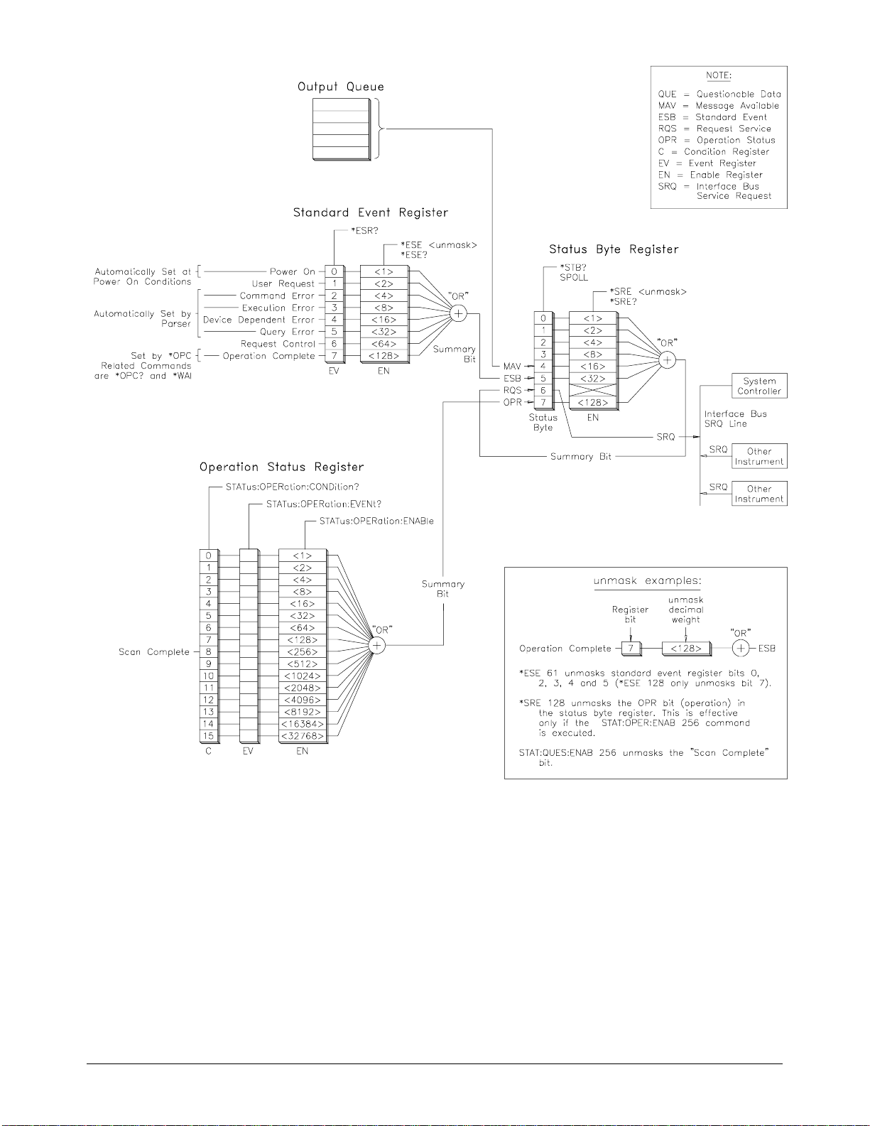
Figure 4-1. Agilent E1465/66/67A Status System Register Diagram
Chapter 4 Relay Matrix Command Reference 79
Page 82

:OPERation
:CONDition?
STATus:OPERation:CONDition? returns the state of the Condition
Register in the Ope rat ion Status Group. The sta te represents conditions
which are part of the instrument’s operation. The switch module driver does
not set bit 8 in this register ( se e
STATus:OPERation[:EVENt]?).
:OPERation:ENABle
Parameters
Comments
Example Enabling Operat ion Stat us Regist e r Bit 8
STATus:OPERation:ENABle <unmask> sets an enable mask to allow events
recorded in the Event Register to send a summary bit to the Status Byte
Register (bit 7). For matrix modules, when bit 8 in the Operation Status
Register is set to 1 and that bit i s e n abled by the
command, bit 7 in the Sta tus Regi ster i s se t to 1.
Parameter Name Parameter Type Range of Values
<
unmask> numeric 0 through 65,535
•
Setting Bit 7 of the Status Byte Register:
STATus:OPERation:ENABle 256 sets bit 7 of the S tat us Byt e Register
to 1 after bit 8 of the Standard Operation Status Register is set to 1.
STATus:OPERation:ENABle
• Related Commands: [ROUTe:]SCAN
STAT:OPER:ENAB 256 Enables bit 8 of the Ope rat ion
Status Enab le Re gister to be
reported to bit 7 (OPR) in the
Status Regis te r.
:OPERation:ENABle?
Comments
Example Query the Operation Status Ena bl e Regi st er
STATus:OPERation:ENABle? returns the bit va lue of the Operati on St a tus
Register.
• Output Format: Returns a decimal weighted value from 0 to
65,535 indic a ti ng which bits are set to tr ue .
• Maximum Value Returned: The value returned is the value set by
STAT:OPER:ENAB<unmask> com mand. Howe ve r, the
the
maximum de c im al weighted value used in this modul e is 256 ( bit 8
set to true) .
STAT:OPER:ENAB? Querie s the Operation Status
Enable Register.
80 Relay Matrix Command Reference Chapter 4
Page 83

:OPERation[:EVENt]?
STATus:OPERation[:EVENt]? returns which bits in the Event Re gister
(Operation Stat us Gr oup) a re se t. The Eve nt Register indicate s when the r e
has been a time-related instrument event.
Comments
• Setting Bit 8 of the Operation Status Register: Bit 8 (Scan
Complete) is set to 1 after a scanning cycle completes. Bit 8 returns
to 0 after sending the
STATus:OPERation[:EVENt]? command.
• Returned Data After Sending the STATus:OPERation[:EVENt]?
command: The command returns +256 if bit 8 of the O peration
Status Regis ter is se t t o 1. Th e com ma nd r etur ns +0 if bit 8 of the
Operation Status Reg ister is set to 0.
• Event Register Cleared: Reading the Event Register with the
STATus:OPERation[:EVENt]? co mman d clears it.
• Aborting a Scan: Aborting a scan will leave bit 8 set to 0.
• Related Commands: [ROUTe:] SCAN
Example Reading the Operation Status Register After a Scanni ng Cycle
STAT:OPER? Retur n s the bit va lues of the
Operation Status Register.
read the register value +256 shows bit 8 is set to 1;
+0 shows bit 8 is set to 0.
:PRESet STATus:PRESet affects only the Enable Register by setting all Enable
Register bits to 0. It does not affect either the "status byte" or the "standard
event status".
PRESet does not clear any of the Event Registers.
Chapter 4 Relay Matrix Command Reference 81
Page 84

SYSTem
The SYSTem subsystem retur ns the error number s a nd e rror me ssages in the
error queue of a matr ix m odule. It can also retur n the types and descr ipt ions
of modules (c ards ) in a switc hbox.
Subsystem Syntax SYSTem
:CDEScription? <
:CTYPe? <
:CPON <
:ERRor?
number> | ALL
:CDEScriptio n? SYSTem:CDEScrip tio n? <number> returns the description of a selected
module (card) in a switchbox.
Parameters
Parameter Name Parameter Type Range of Values
<
number> numeric 1 to 99
number>
number>
Comments
• Agilent E1465A Relay Matrix Module Description: The
SYSTem:CDEScription? <number> command returns:
16 x 16 Mat rix Switch
• Agilent E1466A Relay Matrix Module Description: The
SYST:CDEScription? <number> command returns:
4 x 64 Matri x Switch
• Agilent E1467A Relay Matrix Module Description: The
SYST:CDEScription? <number> command returns:
8 x 32 Matri x Switch
Example Reading the Description of a Card #l Module
SYST:CDES? 1 Return the description.
:CTYPe? SYSTem:CTYPe? <number> ret ur ns the module (card) type of a sel ected
module in a switchbox.
Parameters
Parameter Name Parameter Type Range of Values
<
number> numeric 1 to 99
82 Relay Matrix Command Reference Chapter 4
Page 85

Comments
• Agilent E1465A Relay Matrix Module Model Number:
SYSTem:CTYPe? <number> command returns:
The
HEWLETT-PACKARD,El465A,0,A.04.00
where the 0 after E1465A is the module serial nu mbe r (always 0)
and A.04.00 is an exam ple of the module revision code number.
• Agilent E1466A Relay Matrix Module Model Number:
SYSTem:CTYPe? <number> command returns:
The
HE WLETT-PACKARD,El466A,0,A.0 4.00
where the 0 after E1466A is the module serial nu mbe r (always 0)
and A.04.00 is an exam ple of the module revision code number.
• Agilent E1467A Relay Matrix Module Model Number:
SYSTem:CTYPe? <number> command returns:
The
HEWLETT-PACKARD,El467A,0,A.04.00
where the 0 after E1467A is the module serial nu mbe r (always 0)
and A.04.00 is an exam ple of the module revision code number.
Example Reading the Model Number of a Card #l M odu le
SYST:CTYP? 1 Return the mod el number.
:CPON SYSTem:CPON <number> | A L L se ts the selecte d module (card) in a
switchbox to i ts po wer-on state.
Parameters
Parameter Name Parameter Type Range of Values
<
number> numeric 1 to 99 | ALL
Comments Matrix Module Power-On State: The power-on state is all channels
(relays) open. Note that
switchbox whil e
modu le (card) sp ecified in t he command .
SYSTem:CPON <number> opens the channels in only the
Example Setting Card #1 Module to its Power-On State
SYST:CPON 1 Sets module #1 to power-on
*RST opens all chan ne ls of a ll modules in a
state.
Chapter 4 Relay Matrix Command Reference 83
Page 86

:ERRor? SYSTem:ERRor? retur ns the error numbers a nd c orresponding error
messages in the error queue of a ma trix module. See Appe ndix C for a
listing of so me of the err or numbers and message s.
Comments
• Error Numbers/Messages in the Error Queue: Each error
generated by a ma tr ix module stores a n e rror num be r and
corresponding e r ro r mes sa ge in the error queue. The erro r me ssa ge
can be up to 255 characters long.
• Clearing the Error Queue: An error number/message is removed
from t he qu eue ea ch tim e the
The errors are cleared first-in, first-out. When the queue is empty,
each following
To clear all error numbers/messages in the queue, execute the
command.
• Maximum Error Numbers/Messages in the Error Queue: The
queue holds a maximum of 30 error num be rs /messages for each
switchbox. If the que ue ove rf lows, the last error nu mbe r /m e ssa ge in
the queue is repl a ced by -350, “Too many errors”. The least recent
error numbers and messages remain in the queue and the most recent
are discarded.
Example Reading the Error Queue
SYST:ERR? Query the error queue.
SYSTem:ERRor? command is sent.
SYSTem:ERRor? command returns 0, “No error”.
*CLS
84 Relay Matrix Command Reference Chapter 4
Page 87

TRIGger
Subsystem Syntax TRIGger
[:IMMediate] TRIGger[:IMMediate] causes a trigger event to occur when the defined
The TRIGger command subsystem cont rols the triggeri ng ope r a ti on of relay
matrix mo dul es in a switchbox.
[:IMMediate]
:SOURce <
:SOURce?
trigger source is
source>
TRIGger:SOURce BUS or TRIGger:SOURce HOLD.
Comments
• Executing the TRIGger[:IMMediate] Command: A channel list
must be defined with
INITiate[:IMMediate] command must be executed before
TRIGger[:IMMediate] will execute.
[ROUT e :]SCAN < channel_list> and an
• BUS or HOLD Source Rema ins: If selected, the
TRIGger:SOURce BUS or TRIGger:SOURce HOLD commands
remain in effect after triggering a switchbox with the
TRIGger[:IMMediate] command.
• Related Commands: INITiate, [RO U Te :]SCAN
Example Advancing Scan Using TRIGger Command
This example scans a single-module switchbox from channel 10000 through
10003. Since
channel each time
TRIG:SOUR HOLD Sets trigger source to HOLD.
SCAN (@10000:10003) Defines channel list.
INIT Begin scan, close channel 00.
loop statement Start count loop.
TRIG Advance scan to ne xt ch anne l.
increment loop Increment loop count.
TRIGger:SOURce HOLD is set, the scan is a dva nc e d one
TRIGger is executed.
Chapter 4 Relay Matrix Command Reference 85
Page 88

:SOURce TRIGger:SOURce <source> specifies the trigger source to advance the
channel list dur ing scanning .
Parameters
Parameter Name Par ameter Type Parameter Description
BUS discrete *TRG or GET command
EXTernal discrete Trig In port
HOLD discrete Hold triggering
IMMediate discrete Immediate triggering
Comments
TTLTrg
n numeric TTL Trigger Bus line 0 - 7
• Enabling the Trigger Source: The TRIGger:SOURce comman d
only selects the tr igger source. The
enables the trigger source.
INITiate[:IMMediate] command
• Using the TRIG Command: You can use TRIGger[:IMMediate] to
advance the scan when
TRIGger:SOURce HOLD is selected.
TRIGger:SOURce BUS or
• Using External Trigger Inputs: With TRIGger:SOURce EXTernal
selected, onl y one switchbox at a tim e can use the e xte r na l t ri gge r
input at the Agilent El406A T rig I n por t. The tr igger input is
assigned to the fir st switchbox th at requested the ext ernal trigger
source (with a
TRIGger:SOURce EXTernal command).
• Assigning External Trigger: A switchbox assigned with
TRIGger:SOURce EXTernal remains assigne d to that source until the
switchbox trigger source is changed to
When the source is changed, the external trigger source is available
to the next switc hbox which request s it (with a
TRIGger:SOURce EXTernal command). If a swit ch box r e que st s an
external tri gge r input already assi gne d to another swit c hbox an error
is ge nerated.
BUS, HOLD, or IMMediate.
• Using Bus Triggers: To trigger the switchbox with
TRIGger:SOURce BUS selected, use the IEEE 48 8. 2 Com mo n
command
*TRG or the GPIB Group Execute Tr igger (GET)
command.
• Trig Out Port Shared by Switchboxe s: See the OUTPut
command.
• Related Commands: ABORt, [ROUTe:]SCAN, TRIGger
• *RST Condition: TRIGger:SOURce IMMediate
86 Relay Matrix Command Reference Chapter 4
Page 89

Example Scanning Using Exter nal Triggers
This example uses external triggering (
0000 through 0003 of a single-module switchbox. The trigger source to
advance the scan is the input to the Tri g In por t on the Agilent E1 406A
Command Module. When
INIT is executed, the scan is started and channel
0000 is closed. Then, each trigger received at the Trig In port advances the
scan to the next channel.
TRIG:SOUR EXT Select external triggering.
SCAN (@10000:10003) Scan channels 10000 through
INIT Begin scan, close channel
trigger externally Advance scan to ne xt ch anne l.
Example Scanni ng Using Bus Trigg ers
This example use s bus t rigge r in g (
through 0003 of a single-module swit c hbox. The trigger sour ce t o ad va nc e
the scan is the
INIT is executed, the scan is started and channel 0000 is closed. Then, each
*TRG command advances th e scan to th e n ext chann el.
*TRG command (as set with TRIGger:SOURce BUS). When
TRIG:SOUR EXT) to scan channels
10003.
10000.
TRIG:SOUR BUS) to scan channels 0000
TRIG:SOUR BU S Select interface (bus) triggering.
SCAN (@10000:10003) Scan channels 10000 through
10003.
INIT Begin scan, close channel
10000.
loop statement Loop to scan all channe l s.
*TRG Advance scan using bus
triggering.
increment loop Increment loop count.
:SOURce? TRIGger:SOURce? returns the current trigger source for the switchbox.
Comman d re turns BUS, EXT, HOLD, IMM, or TTLT for sources
EXTernal, HOLD, IMMediate, or TTLTrg respectively.
Example Query Trigger Source
This example sets e xte rna l triggering and que r ies the trigger source . Sinc e
external triggering is set,
TRIG:SOUR EXT Set externa l trigger source
TRIG:SOUR? Query trigger source
TRIG:SOUR? returns EXT.
BUS,
Chapter 4 Relay Matrix Command Reference 87
Page 90

IEEE 488.2 Common Commands
The following ta ble lists the IEE E 488. 2 Common (*) commands that ap ply
to the relay matrix module. The operation of some of these commands is
described in Cha pter 3 of this man ua l. For mor e inf or m at ion on Common
commands, refer to the Agilent E1406 Command Module User’s Manual or
the ANSI/IEE E Standard 488.2-1987.
Command Title Description
*IDN?
*RST
*TST?
*OPC
*OPC?
*WAI
*CLS
*ESE<unmask>
*ESE?
*ESR?
*SRE<unmask>
Identificatio n Query
Reset
Self-Test Query
Operation Compl ete
Operation Compl ete Q uer y
Wait to Continue
Clear Status Register
Event Status Enab le
Event Status Enab le Qu ery
Event Status Regist er Quer y
Service Request En able
Returns identifica tio n stri ng of the matrix module.
Opens all chan nel relay s.
Returns
Returns
Returns
Returns
Returns
Sets the Reques t for OPC f lag w hen all pending operations have
completed. A lso set s O PC bit in t he St andard Event Register.
Returns a
completed. Used t o synchronize betwe en m ul tiple inst r um ent s.
Prevents an inst ru me nt from execu ting another command until the
operation caus ed by t he pr evi ou s com m and i s fin ished. S ince al l
instruments no rm all y perfo rm sequential operatio ns, th is com ma nd
causes no cha nge to t he i nst ru me nt’s oper at ion.
Clears all even t regist er s, the Re ques t for OPC f l ag, and al l queu es
(except output que ry).
Used to set the bi ts in the Event Status Enable R egist er .
Queries the current contents in the Event Sta tu s Enabl e Register.
Queries and clear s cur re nt the n cont ents in the Standard Event Sta tu s
Register.
Used to set the S ervic e Request Enable Register bi ts , and
corresponding Se rial P oll Stat us R eg is te r bits, to ge ner ate a ser vi ce
request.
+0 if self-test pass e s.
+cc01 for firmware error.
+cc02 for bus error.
+cc10 if an interrupt wa s exp ect ed but not received.
+cc11 if the busy bit was not hel d f or 7 mse c.
1 to the output qu eue when all pending opera tion s have
*SRE?
*STB?
*TRG Trigger Triggers the switchbox to advance the scan when scan is enabled and
*RCL
*SAV
Service Request En able query
Read Status Byte Query
Recall Saved State
Save State
Queries the current contents in the Service Request Enable Register.
Queries the current contents in the Status Byte Register.
trigger source is TRI G ger :SOUR c e B US
Recalls previ ously st or ed m at rix co nf ig ura tion.
Stores the curr ent ma tri x conf igur at i on in me mo ry.
.
88 Relay Matrix Command Reference Chapter 4
Page 91

SCPI Command Quick Reference
The follow ing table summarizes the SCPI commands for the matr ix
modules.
Command
Command/Parameter Description
Subsystem
ABORt ABORt Abort a scan in progr ess .
ARM :COUNt <number> MIN | MAX
DISPlay :MONitor[:STATe] <number>
INITiate :CONTinuous <mode>
OUTPut :EXTernal[:STATe] <mode>
[ROUTe:] CLOSe <channel_list>
STATus :OPERation:CONDition?
:COUNt? [MIN | MAX]
:MONitor:CARD <number>
:CONTinuous?
[:IMMediate]
:EXTernal[:STATe]?
[:STATe] <mode>
[:STATe]?
:TTLTrg
:TTLTrg
CLOSe? <channel_list>
OPEN <channel_list>
OPEN? <channel_list>
SCAN <channel_list>
:OPERation:ENABle <unmask>
:OPERation:ENABle?
:OPERation[:EVENt]?
:PRESet
n[:STATe] <mode>
n[:STATe]?
Multiple scans per INIT command.
Query numb er of scans.
Turns monitor mode on or of f.
Selects the module in a switchbox to be monitored.
Enables/disables continuous scanning.
Query contin uous scan state.
Starts a scanning cycle.
Enables/disables Trig Out pulse.
Query port enab le sta te.
Enables/disables Trig Out pulse.
Query port enab le sta te.
Enables/disables TTL Trigger bus line pul se .
Query TTL Trigg er Bus line stat e.
Close channel(s).
Query channe l(s) clo sed.
Open channel (s).
Query channe l(s) opened.
Define channe ls for scanning.
Returns state of t he C ondition Register in the O per at io n Sta tu s
Group.
Enables the Oper at i on St at us Regi st er to set a bit i n the S ta tu s
Register.
Query the cont ent s in the O per at io n Sta tu s Regi st er .
Returns status of Operation Stat us Register.
Sets all Enable Reg iste r bits to 0.
SYSTem :CDEScription? <number>
TRIGger [:IMMediate]
:CTYPe? <number>
:CPON <number> | AL L
:ERRor?
:SOURce BUS
:SOURce EXTe rna l
:SOURce HOLD
:SOURce IMMe di ate
:SOURce TTLTr g
:SOURce?
n
Returns descr ip tion of module in swit chb o x.
Returns the module type.
Sets specifie d mo dule t o its power-on state.
Returns error number/message to err or queue .
Causes a trigger to occur.
Trigger source is *T RG .
Trigger source is Trig In port.
Hold off triggering.
Continuous (in te rna l) trigger ing.
Trigger source is TTL trig ger bu s lin e (0 - 7).
Query scan trigger source.
Chapter 4 Relay Matrix Command Reference 89
Page 92

Notes
90 Relay Matrix Command Reference Chapter 4
Page 93

Appe ndix A
Specifications
General
Module Size/ Device Type:
C-size VXIbus, registe r based, A16/D16,
Interrupter (levels 1-7, jumper selectable)
Relay Life:
@ No load : 10
@ Full load : 10
Terminals:
Screw type, maximum wire siz e 18 AWG
Power Requirements:
Voltage: +5 +12 V
Peak Module Curre nt ( A ): 0.10 0.18
Watts/slot: 5 W
Cooling/slot: 0.08 mm H
Operating Temperature: 0 - 55° C
Operatin g Humid it y: 65% RH, 0 - 40° C
7
operations
5
operations
O @ 0.42 liter/sec
2
Input Characteristics
DC Performan ce
Thermal Offset per Channel:
<5µV (differential H-L)
Closed Channel Resistance:
Initial <4.0Ω
End of life <10.0Ω
Insulation Resistance
(between any two points, single module):
8
10
Ω (at 40° C, 95% RH)
9
Ω (at 25° C, 40% RH)
10
AC Performan ce
Closed Channel Capacitance (Hi-Lo, Lo-Chassis):
Hi to Lo <270 pF
Hi to GND <430 pF
Lo to GND <440 pF
Bandwidth (-3dB): Zload = Zsource = 50Ω:
>10 MHz
Maximum Volt age Ter m in al t o Ter m in al:
200 Vdc; 170 Vac
Maximum Voltage Te r min al t o Cha ssis:
200 Vdc 170 Vac
Maximum Current per Channel (non-inductive):
1 Adc; 1A ac peak
Maximum Power per Channel:
30 Wdc; 62.5 VA ac resistive load
(238 V ac peak to peak)
rms
(238 V ac peak to peak)
rms
Crosstalk Betw een Chan nels:
See tables on next page.
Appendix A Specifications 91
Page 94

Agilent E1465A AC P erfor ma nce. Speci fi cati ons ar e f or 16 x 16 matri x, for Z(load) = Z(source) = 50 Ω.
AC specifications apply with no more than one crosspoint clos ed per row or colu mn .
Bandwidth (-3dB ): >10M Hz C r osst alk ( dB )
Within a Card (worst pat h)
Closed Path to Closed Path (typical)
Open Row to Open Row (typical )
Open Row to Open Column (ty pical )
Open Column to Open Column ( ty pical)
Module to Module
2
(Represents 16 x 32 Conf i gur at ion)
Closed Path to Closed Path (typical)
Open Row to Open Row (typical )
Open Row to Open Column (ty pical )
Open Column to Open Column ( ty pical)
1
3
3
3
3
3
3
3
3
<10kHz
-78 dB
-93 dB
-84 dB
-86 dB
-78 dB
-84 dB
-84 dB
-93 dB
<100kHz
-57 dB
-73 dB
-63 dB
-65 dB
-58 dB
-66 dB
-63 dB
-72 dB
<1MHz
-41 dB
-56 dB
-47 dB
-48 dB
-43 dB
-52 dB
-48 dB
-48 dB
Closed-Channel C apacitance
Hi to Lo: <270pF
Hi to Ground: <430pF
Lo to Ground: <440pF
Agilent E1466A AC P erfor ma nce. Speci fi cati ons ar e f or 4 x 64 matr ix, for Z(load ) = Z( source) = 50 Ω.
AC specifications apply with no more than one crosspoint clos ed per row or colu mn .
Bandwidth (-3dB ): >10M Hz C r osst alk ( dB )
Within a Card (worst pat h)
Closed Path to Closed Path (typical)
Open Row to Open Row (typical )
Open Row to Open Column (ty pical )
Open Column to Open Column ( ty pical)
Module to Module
2
(Represents 4 x 12 8 Conf i gur at ion)
Closed Path to Closed Path (typical)
Open Row to Open Row (typical )
Open Row to Open Column (ty pical )
Open Column to Open Column ( ty pical)
1
3
3
3
3
3
3
3
3
<10kHz
-72 dB
-73 dB
-84 dB
-92 dB
-66 dB
-68 dB
-84 dB
-92 dB
<100kHz
-50 dB
-52 dB
-64 dB
-70 dB
-45 dB
-46 dB
-64 dB
-71 dB
<1MHz
-34 dB
-37 dB
-47 dB
-52 dB
-29 dB
-29 dB
-48 dB
-52 dB
Closed-Channel C apacitance
Hi to Lo: <270pF
Hi to Ground: <430pF
Lo to Ground: <440pF
Agilent E1467A AC P erfor ma nce. Speci fi cati ons ar e f or 8 x 32 matr ix, for Z(load ) = Z( source) = 50 Ω.
AC specifications apply with no more than one crosspoint clos ed per row or colu mn .
Bandwidth (-3dB): >10MHz Crosstalk (dB)
Within a Card (worst pat h)
Closed Path to Closed Path (typical)
Open Row to Open Row (typical )
Open Row to Open Column (ty pical )
Open Column to Open Column ( ty pical)
Module to Module
Closed Path to Closed Path (typical)
Open Row to Open Row (typical )
Open Row to Open Column (ty pical )
Open Column to Open Column ( ty pical)
2
(Represents 8 x 64 Co nf igura tion)
1
3
3
3
3
3
3
3
3
<10kHz
-75 dB
-91 dB
-85 dB
-92 dB
-72 dB
-74 dB
-92 dB
-82 dB
<100kHz
-54 dB
-59 dB
-64 dB
-71 dB
-51 dB
-53 dB
-72 dB
-64 dB
<1MHz
-38 dB
-43 dB
-47 dB
-54 dB
-33 dB
-38 dB
-56 dB
-50 dB
Closed-Channel C apacitance
Hi to Lo <270pF
Hi to Ground <430pF
Lo to Ground <440pF
NOTES: 1 Specifications are for worst crosspoint.
2 Chaining cable used to connect module s (Agilent P/N E1466-80002) .
3 Typical is defined as the worst crosspoint test result from one or two matrix modules.
92 Specifications Appendix A
Page 95

Relay Life Electromechanical relays are subject to normal wear-out. Relay life
depends on several factors. The effects of loa ding and switching f req ue nc y
are briefly discussed below:
Relay Load. In general , higher power switching reduces relay li f e. In
addition, capacitive/inductive loads and high inrush currents (e.g., turning
on a lamp or sta rt ing a motor) reduces relay l if e . Exceeding specified
maximum inputs can c ause catastrophic failure.
Switching Frequ enc y. Relay contacts heat up when switched. As the
switching frequency increases, the contacts have less time to dissipate heat.
The resulting increase in contact temperature also reduces relay life.
End-of-Life
Detection
Replacement
Strategy
A preventive ma intenance routin e ca n pr ev en t pr obl e ms c a use d by
unexpected relay f a ilure. The end of the li fe of the rel a y can be de te rmined
by using one or mor e of the three methods des cri be d be low. The be st
method (or combination of met hods), as well as the fa il ur e cr it eria, depends
on the applica tion in wh ich the re lay is use d.
Contact Resistance. As the relay begins to wear ou t, its contact resistance
increases. When the resistance exceeds a predetermined value, replace the relay.
Stability of Conta ct Re sis ta nce . The stability of the contact resistance
decreases with age. Using this method, the contact resistance is measured
several (5-10) times, and the variance of the measurements is determined.
An increase in the variance indicates deteriorating performance.
Number of Operations. Relays can be replaced after a predetermined
number of contact cl osures. However, this m ethod requires knowledge of
the applied load and life specifications for the applied load.
The replaceme nt st r at e gy de pe nds on the application. If som e re la ys a re
used more often , or a t a h igh er load, than the others, the relays can be
individually replaced as needed. If all the relays see similar loads and
switching frequencies, the entire circuit board can be replaced when the end
of relay life approa ch es . The se nsitivity of th e appl ic a ti on should be
weighed against the cost of replacing relays with some useful life remaining.
Note Relays that wear ou t nor m al ly or fail due to mi sus e sh ould not be consider e d
defective and are not cov ered by the product’s warrant y.
Appendix A Specifications 93
Page 96

Notes
94 Specifications Appendix A
Page 97

Using This Appendix
The Agilent E1465A/E1466A/E14 67A ma trix modules are regi ste r -ba se d
modules. W he n a SC PI command is sent to the matr ix, the Agilent E1406A
Command Module parses the co mmand and progra ms t he ma tr ix at the
register level.
Register-based programming is a series of reads and writes directly to the
matrix module registers. Writing directly to the registers increases
throughput speed since it eli mi na tes the command parsi ng a nd a llows the
use of an embedde d c ont ro ller. This appendix include s inf or mation on th e
following:
• Addressing the Registers . . . . . . . . . . . . . . . . . . . . . . . . . . . . Page 95
• Register Descriptions . . . . . . . . . . . . . . . . . . . . . . . . . . . . . . . Page 98
• Register-Based Programming Examples . . . . . . . . . . . . . . . . Page 104
Appendix B
Matrix Registers
Addressing the Registers
Register addresses for register-based modules are located in the upper 25%
of VXI A16 address space. Every VXI modul e (up t o 256 de vi c es ) is
allocated a 32-word (64-byte) block of addresses.
Figure B-1 shows the r eg ist e r addr e ss l oc at ion within A16 as it m ight be
mapped by an embe dde d c ontroller. Figure B-2 shows t he loc a ti on of A16
address space in the Agilent E1300/01 Mainframe and Agilent E1 405/06A
Command Module.
When you are rea ding or writing to a matrix module re gis te r , a he xa de ci mal
or decimal regi ste r ad dr es s needs to be specified . Thi s a ddr ess c onsists of a
base address plus a register offset:
Register Address = Base Address + Register Offset
Appendix B Matrix Registers 95
Page 98
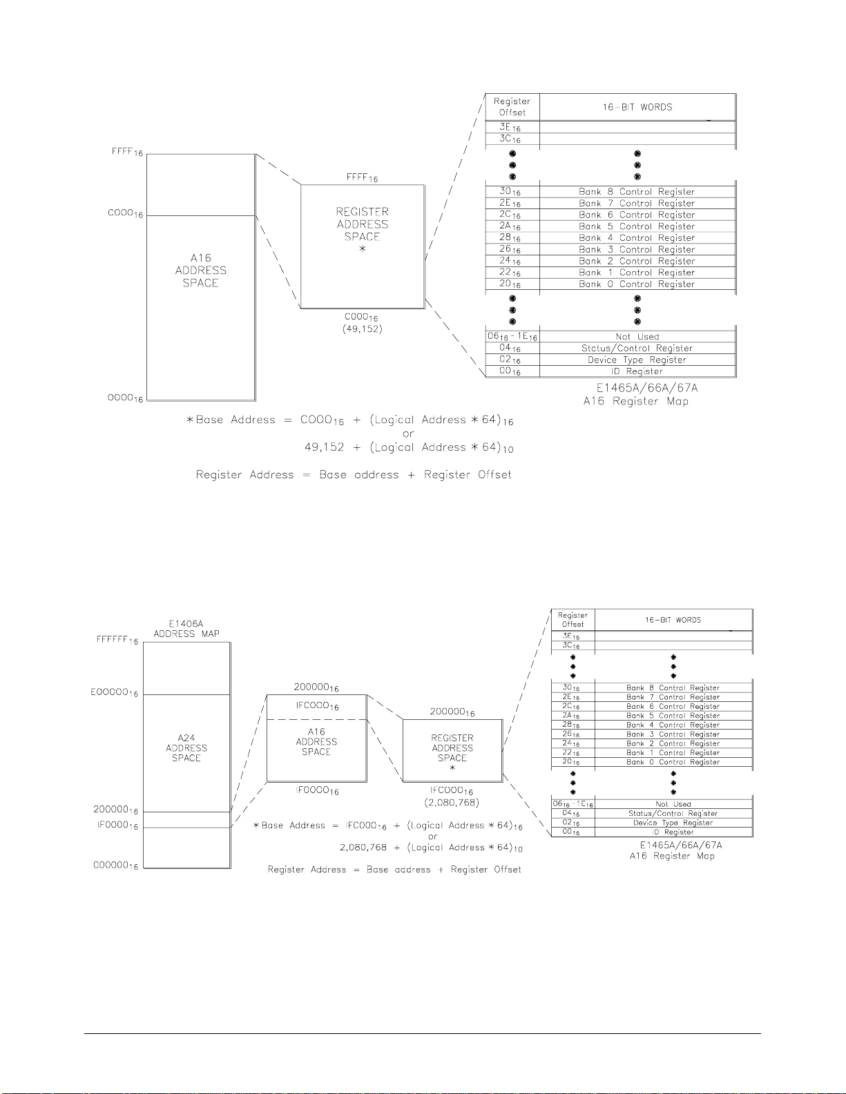
Figure B-1. Registers within A16 Address Space
Figure B-2. Registers within E1301/E1406 A16 Address Space
96 Matrix Registers Appendix B
Page 99

The Base Address The base address used in r egist er-based programming depends on whether t he
A16 address space is outside or inside the Agilent E1406A Comm and Module.
Address Space
Outside the Comm and
Module
Address Space Inside
the Command Module
When the command module is not part of your VXIbus system (Figure B-1),
the matrix module’s base address depends on the command module used:
Command Module Address + C000
+ (LADDR * 64
16
)16
or
Command Module Address + 49,152 + (LADDR * 64)
Where C000
(49,152) is the sta rting location of the VXI A16 add ress es ,
16
LADDR is the matrix module’s logi cal ad dress, and 64 is the numb er of
address bytes pe r re gister-based module. For example , the ma trix module’s
factory-set logical address is 120. If the address is not changed and an
Agilent E1480 A (V/ 360) Co ntr oller is used, th e ma tr ix module will have the
following base ad dr ess:
C000
+ (120 * 64)16 = DE0016
16
or
49,152 + (120 * 64) = 56,832
When the A16 address space is inside the command module (Figure B-2),
the matrix m odule’s base address is computed as fo llows:
1FC000
+ (LADDR * 64)
16
16
or
2,080,768 + (LADDR * 64)
Where 1FC000
(2,080,768) is the sta r ting locatio n of the regi ster
16
addresses, LADDR is the matrix module’s logical address, and 64 is the
number of address by te s pe r VXI mo dul e. Aga in, the matrix modul e’s
factory-set logical addre ss i s 120. If the address i s not cha nged, the matrix
modules will ha ve the following base add ress :
1FC000
+ (120 * 64)16 = 1FDE00
16
16
or
2,080,768 + (120 *64) = 2,088,448
Register Offset The register offset is the register’s location in the block of 64 address bytes.
For example, if you want to write to the matrix module’s Status Register,
you would add a regist e r offse t of 04
command to this register, the of f se t is added to the base a ddr e ss to form the
following reg ist e r addr e ss:
1FDE00
+ 0416 = 1FDE04
16
or
2,088,448 + 04 = 2,088, 452
(see next section ). Whe n you wr ite a
16
16
Appendix B Matrix Registers 97
Page 100

Register Descriptions
The matrix modules contain 2 read registers, 1 read/write register, and 16
write registers. This section describes each matrix module register.
Readin g and
Writing to the
Registers
The Manufacturer’s
Identification Register
Address
Base + 00
1514131211109876543210
16
Example programs are provided at the end of this appendix that show how
to read and write to these registers. You can read or write to the following
matrix mo dule registers:
• The Manufacturer’s Identification Register (read only)
• The Device Type Register (read only)
• The Status/Control Register (read or write)
• Relay Control Registers (a total of 16 write-only r eg ist e rs )
Each of these regi sters is discusse d in the following sections.
The manufacturer’s identification register is at offset address 0016 and
returns FFFF
module is an A16 register-based module . This register cannot be written to.
Manufacturer ID Register
. This shows Ag il e n t a s the manufact ur er a nd that th e
16
FFFF
16
The Device
Identification Register
Address
Base + 02
1514131211109876543210
16
The Status/Control
Register
The device identification register is at offset address 0216 and returns
0122
if you have an Agilent E1465A/E1466A/E1467A Matrix Mod ule.
16
To determine whi ch module you have, you m ust read the status/ control
register. The de vic e ide ntification regi ste r cannot be written to.
Device Identification Register
0122
16
The status/c ont ro l r eg ist e r i s at of fs et ad dr es s 0416 and informs the user
about the module’s status and con fi gur ation. (See following e xa mp le . )
98 Matrix Registers Appendix B
 Loading...