

5991-2059EN Using RF Recording Techniques to Resolve Interference Problems - Application Note c20140701 [20]
Agilent 5991-2059EN Using RF Recording Techniques to Resolve Interference Problems - Application Note c20140701 [20] Datasheet
Page 1
Keysight Technologies
Using RF Recording Techniques
to Resolve Interference Problems
Application Note
Page 2

Introduction
System engineers characterizing interference in either commercial wireless or Electronic Warfare
(EW) applications today face a difcult task. Interference, dened as anything that is not the signal
expected, is a highly pervasive problem; one that can be quite difcult to address since its measurement can be unpredictable. Despite the challenge, the task of nding, identifying and analyzing interfering signals, intentional or not, in a crowded spectrum has become increasingly important in
a wide array of applications.
This application note introduces a method for using gapless recording to resolve RF interference
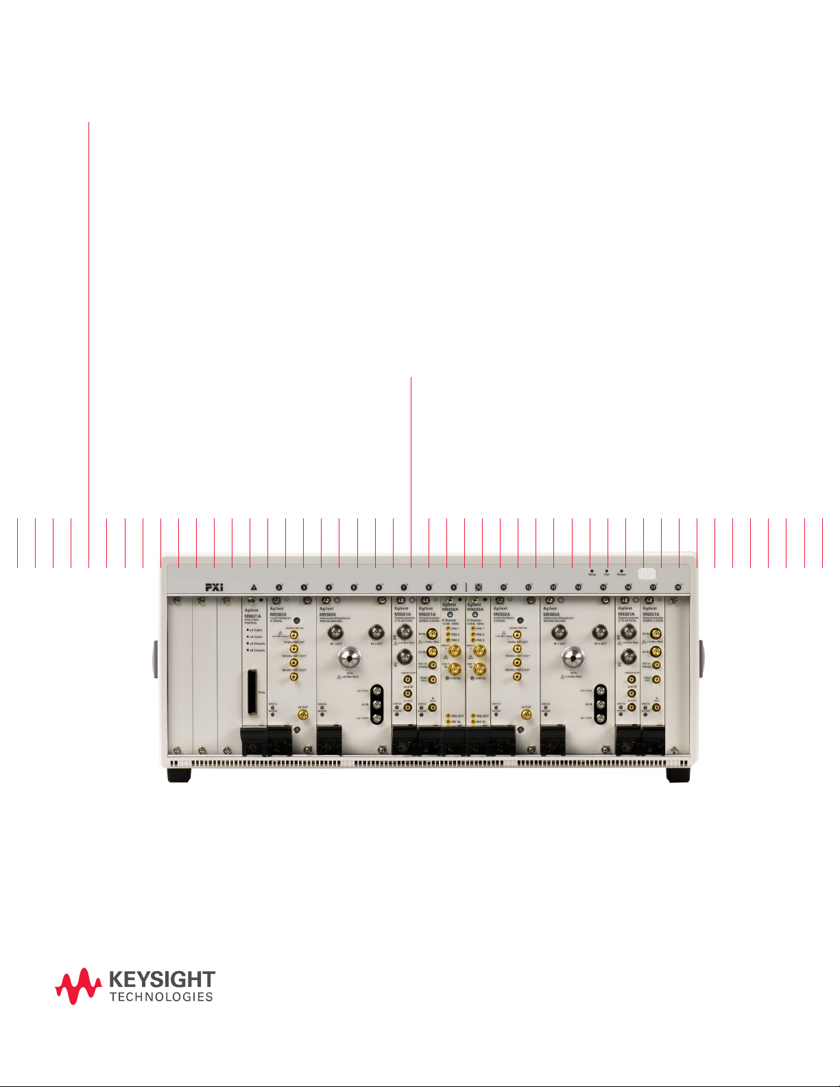
problems in complex RF environments. The method uses the Keysight Technologies dual-channel
M9392A PXI Vector Signal Analyzer with either a regular PC hard disk drive or external mass storage. When recording at wide bandwidths for long durations a RAID storage system is required. Data
interface cards and modules are also used, as are Keysight’s M9392A with the 89600 Vector Signal
Analyzer (VSA) software. With gapless recording, engineers can now measure data continuously over
long durations and ensure the capture of all RF events of interest when they occur.
Page 3
Measurement
ADC DSP
RAM
RF
Input
Signal Analyzer Block Diagram
Preselect
Down -
Convert
Digitize
Store Process
Acquire
Data
Move Data from Digitizer to µP
Read &
Store
µP
Display
Challenges
Generally speaking, there are two primary goals of RF interference testing: to
ensure interoperability and compatibility. Interoperability testing focuses on design compliance to a published standard, as well as margin testing, which helps
engineers understand how well a system meets design criteria in the presence
of real-world signal levels and interference. Compatibility testing, on the other
hand, focuses on the “unintended interactions” between a system-under-test
and other RF systems. It’s important for engineers to understand whether radios from different vendors can interoperate with one another, as well as if all the
systems in an RF environment can play together nicely. Ascertaining a system’s
susceptibility to impact from and on other RF assets may also be critical.
Regardless of the RF interference testing in question, a number of critical
measurement challenges exist. First and foremost, measuring RF target signals
like intentional or unintentional interference in complex RF environments can be
unpredictable. Additionally, intermittent failure modes make data capture particularly challenging. Consequently, when the root cause of a problem is not yet
known, it can be difcult for engineers to setup a measurement that captures
the failure.
How can engineers capture a target RF signal and/or the cause of interference
when they don’t know what the signal or culprit interferer is, when or where it
will occur, or how long it will last? Unfortunately, using a typical signal analyzer
performing continuous long-duration recording offers little help.
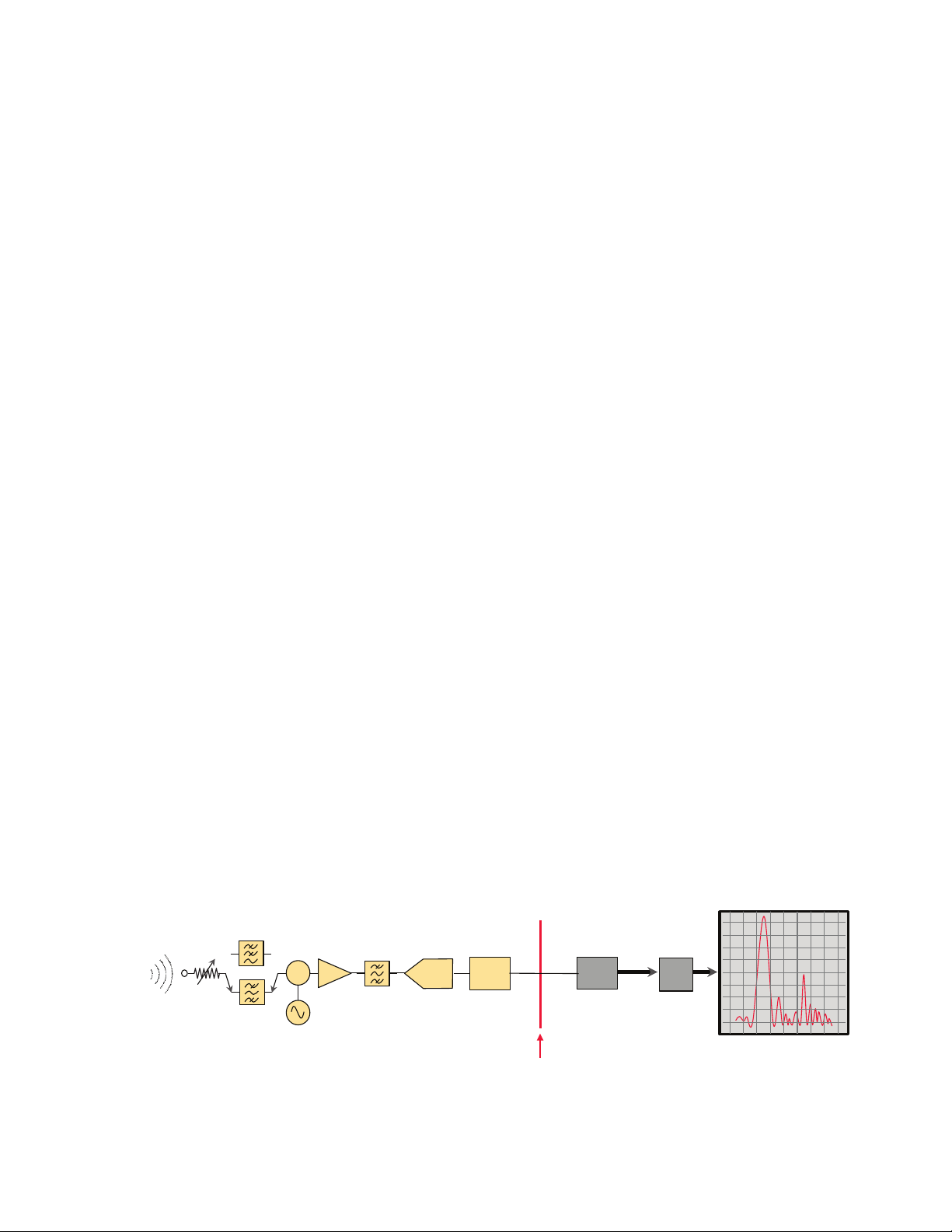
To better understand why this approach falls short consider the high-level block
diagram of a typical signal analyzer shown in Figure 1. The main limitation to
long-duration recording is that test equipment typically has limited on-board
memory. Signals-of-interest enter the analyzer’s RF input and are processed by
the subsequent stages, resulting in the displayed waveform shown on the right.
Up until the blue ver tical line, between the DSP and RAM blocks, all of the
signals-of-interest within the instrument’s capture bandwidth are processed
in real-time, assuming a xed local oscillator. However, once the samples ll
the memory buffer or RAM, the instrument no longer looks at incoming digital
samples. Instead, it must process previously recorded samples.
The signal analyzer does not capture any samples while it post-processes the
previously captured data, effectively creating a gap in its data acquisition.
Consequently, if events occur while the previous event is being processed or if
the new event lasts longer than the available memory, it falls into this gap and
may be missed. Moreover, the analyzer’s trigger setup only captures signals for
one set of limited conditions. Once the analyzer fails to capture the event, it is
gone forever.
Figure 1. Shown here is a t ypical signal analyzer block diagram.
3
Page 4
Acquisition Acquisition AcquisitionRead Read Read
GAP
GAP
GAP
FAILURE
MISSED
Introducing Gapless
ADC DSP
RAM
RF
Input
Signal Analyzer Block Diagram Modified for Gapless Recording
Preselect
down-convert
Digitize
Store process
Acquire
data
PC Digitizer
Storage
RAID
RAM
buffer
Recording
While resolving RF interference problems in complex RF environments can be
a tricky task, gapless recording of fers a viable solution to the measurement
challenges presented by the typical signal analyzer. The technique solves the
problem of not knowing when or where an interference event will occur, or how
long it will last, by enabling continuous acquisition of data over long durations.
Because there is no gap in the data recorded, the signal-of-interest, such as an
intermittent RF event, is easily captured.
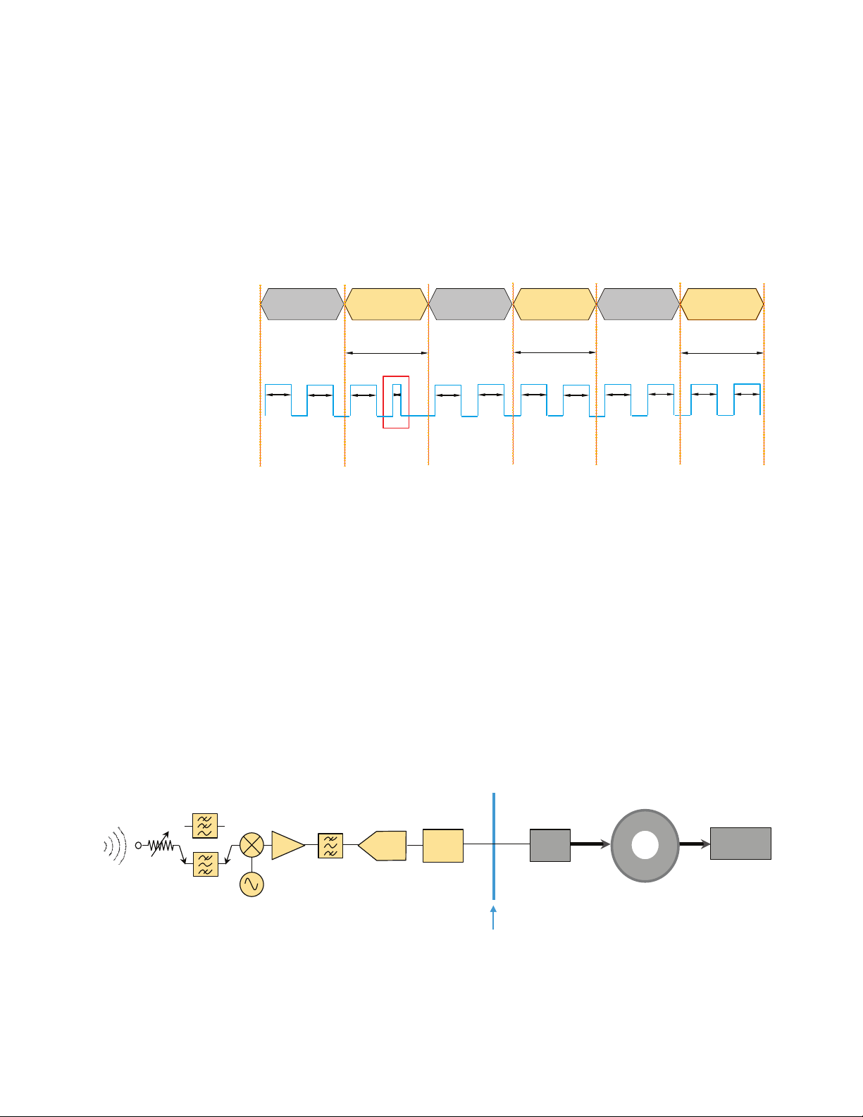
For comparison purposes, consider the data acquisition from a typical signal
analyzer with limited on-board memory, as shown in Figure 2. Note the gaps in
data that occur once its memory is lled up.
Figure 2. With a t ypical analyzer, once its memory is lled up, data is “read” from the digitizer to
the microprocessor for processing and display. During this “read,” any new samples available at the
digitizer cannot be processed and are missed, creating a gap in the continuous acquisition of data
and resulting in failures being missed.
Now, consider an example of a signal analyzer modied for gapless recording (Figure 3). It is the same signal analyzer shown in Figure 1; however, it now
includes a high-speed data link or bus that allows the engineer to move data
from memory as it is acquired. By bypassing processing and display updates,
and writing the acquired data directly to nal storage using a circular RAM buffer, it’s possible to create high-bandwidth recordings without gaps in the data.
With a circular RAM buffer, the engineer can simultaneously write to and read
from it. When recording at wide bandwidths for long durations, a RAID storage
system is required.
Figure 3. A signal analyzer modied for gapless recording.
4
Page 5
Read
>500 MB/s
Read
>500 MB/s
Read
>500 MB/s
GAPLESS
FAILURE
CAPTURED
Continuous acquisition 500MB/s
Introducing Gapless
Recording (continued)
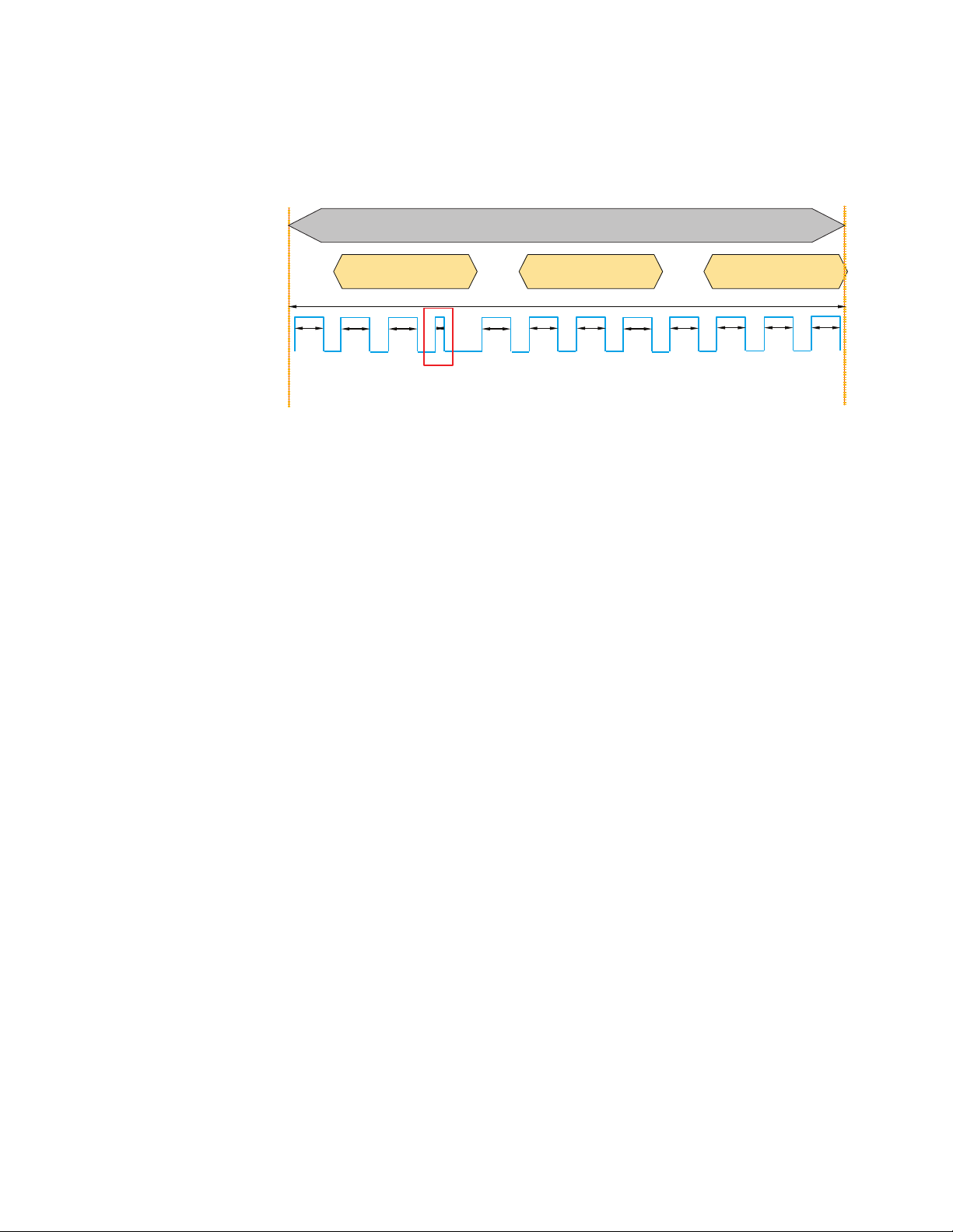
An image of a gapless acquisition taken using the modied analyzer is shown in
Figure 4. Note that unlike the gap-lled acquisition in Figure 2, this acquisition
is continuous. Recording the acquisition of data does not stop during the “read”
because it happens in parallel with the acquisition. Without gaps in the data
record, the signal-of-interest—in this case a failure—is easily captured.
Figure 4. In this gapless acquisition example data is being moved at a sustained rate of 5 00 MB/s
(equivalent to a 100-MHz bandwidth recording).
5
Page 6
A Viable Recording
Solution (continued)
An example of a gapless recording solution is Keysight’s dual-channel M9392A
PXI Vector Signal Analyzer, which can provide two independently tunable channels—each capable of recording data at a rate of 100-MHz bandwidth over
many hours. The M9392A is a ve-module solution. Each module in the system
exists as a discrete component in its own right, with its own driver and soft
front panel. The overarching control of the ve modules is provided by a layer of
instrument software called the M9392A.
The M9392A is used with either a regular PC hard disk drive (HDD) or external
mass storage. The HDD is used in cases where the required capture duration is only a few tens of seconds. External mass storage can be used with the
M9392A for long duration captures requiring more throughput and capacity.
When recording at wide bandwidths for long durations, a RAID storage system
is required.
Keysight’s gapless recording system is available in predened packages that
have been tested to guarantee sustained data rates. The congured systems
include data interface cards and modules, and can be used with Keysight’s
89600 VSA signal analysis software to speed the process of nding, analyzing
and xing problems.
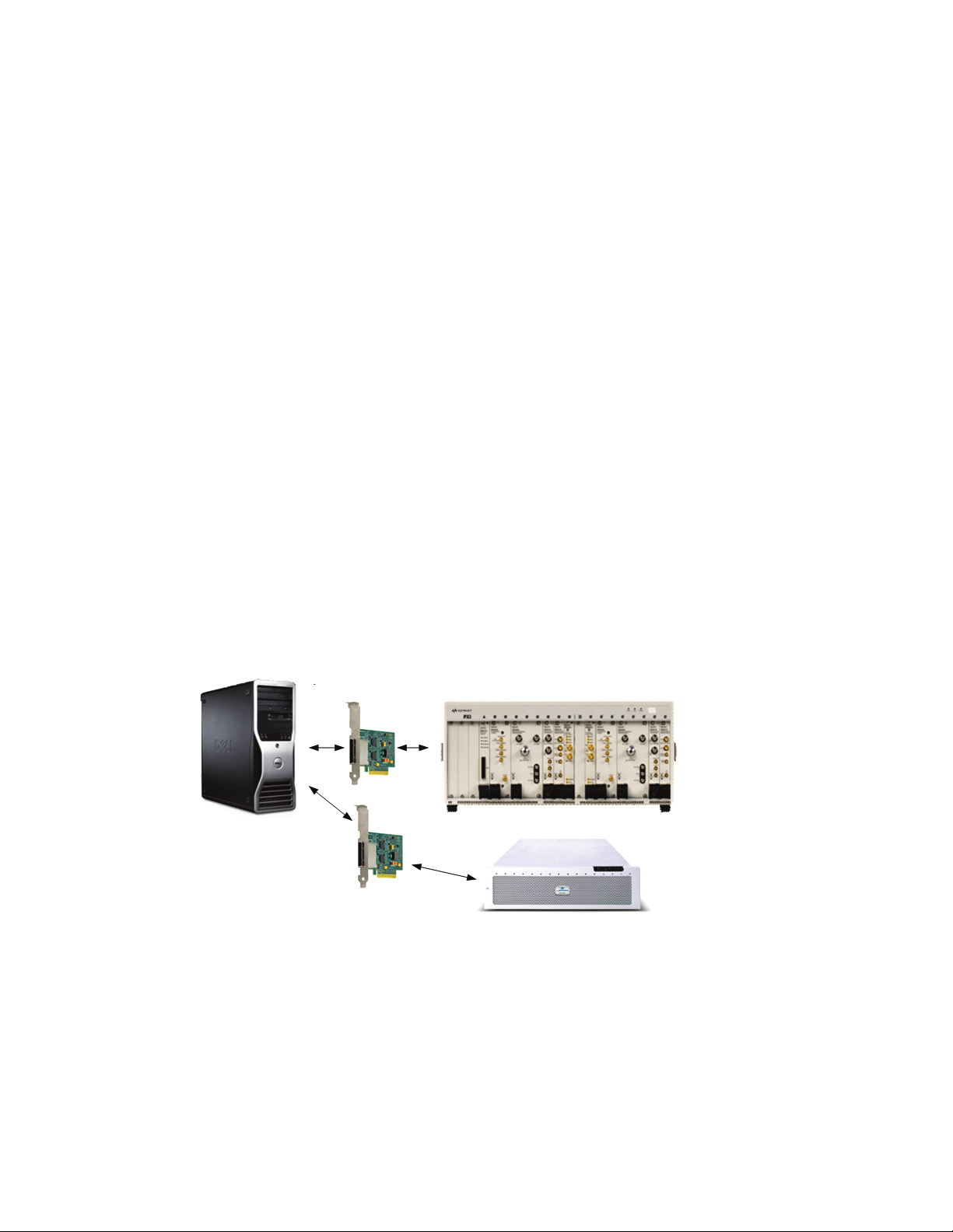
An example of a congured M9392A recording system with 32 TB of storage is
shown in Figure 5. This system can be connected to a PXI chassis or external
workstation computer using a very fast PCIe® link. In this case, the JMR RAID
system is congured to “look” like an external drive to the PC. To achieve high
storage bandwidth, the recorded stream of data is striped (e.g., divided up and
written to multiple hard disks in parallel). The striping of data across the disk
array is controlled by the RAID host controller on the JMR end of the link.
Dell T3500/T5500
workstation
Processing
Measurement hardware
2 channel M9392A VSA system
M9047A x8
desktop adaptor
Can be replaced with 2 PCIe
port host adaptor if configured
for 2 virtual RAID drives
Data interface cards
Figure 5. Shown here is Keysight’s RF recording hardware congured for 32 TB of storage. The
package includes inter face cards and modules that rely on the wide bandwidth and fast throughput
bene ts of PCIe.
JMR RAID storage solution
Storage
– 2 x M9392A PXI VSA
– M9018A PXI chassis
– M9021A interface
– 10 MHz -26.5GHz
– 100MHz recording BW
– Single controller/Dual controller
8, 16, 32 TB
6
Page 7
PC controller
DDC RAM
Data acquisition
Circular RAM
buffer on PC
controller
Final storage
Streaming data Streaming data
Multi-rate digitizer with data
decimation
RAID controller and disk array
PC
HDD
>500 MB/s >500 MB/s
<<500 MB/s
High speed PCIe
High speed PCIe
A Viable Recording
Solution (continued)
Gapless recording data ow
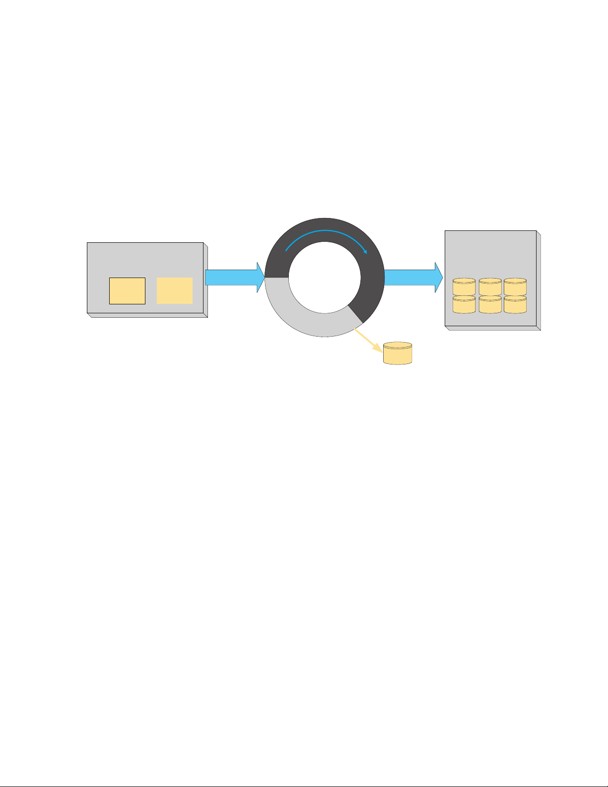
A high-level block diagram implementation of Keysight’s wideband recording
solution is shown in Figure 6. Note that its’ wideband digitizer begins acquisition of data to RAM as soon as it is armed. The M9392A software, running in
the PC controller, controls the data acquisition and sets up the circular buf fer
in recording mode. If the recording mode is congured, the controlling software
instantiates a circular buffer in the PC controller RAM. Recording then begins
as soon as the trigger is received. For gapless recording, the average streaming
data throughput from the digitizer to storage must match the data acquisition
bandwidth.
Figure 6. Highlighted here is the gapless recording ow for the M9392A solution. The data in the PC
RAM is writ ten out at a very high transfer rate to a RAID array. The RAID is required since a single
HDD cannot store data at the necessary sustained rates.
In recording mode, there is a continuous transfer of blocks of data from the digitizer to
the PC controller RAM. In a variable-rate system, data decimation saves data bandwidth
since only the data needed for the measurement is transferred. This capability is important
in scenarios where the digitizer has a very high sample rate or multiple channel support
is required. In each case, the RAM in the digitizer and the RAM in the controller would
act as buffers between acquisition and final storage when dealing with slight variances in
throughput during recording.
7
Page 8
Digitizer acquisition blocks
XStart
Time in acquisition block
Trigger
event
Begin capture
from here
Arm
A Viable Recording
Solution (continued)
Triggering a recording
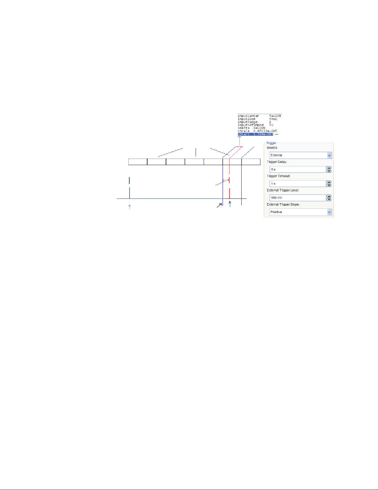
With the M9392A wideband recording solution, data is block transferred from
the digitizer to the controller memory. The actual block size may be quite small.
When the digitizer is armed, the controlling software immediately begins the
process of copying acquired data to the PC controller RAM. At the same time,
the digitizer watches the external trigger input or checks the power on its
incoming RF signal using its magnitude trigger. There is both an external trigger
and magnitude trigger built into the DDC. Data in the PC RAM is not copied to
nal storage until the trigger event is detected (Figure 7).
Figure 7. In this implementation, each recording session includes a text header le that instructs
any playback system how to process the data. T he header le includes RF center frequency, sample
period, amplitude scaling factor and trigger event time within the start data block.
8
Page 9
Pre-trigger data
Triggered data
Time and data flow
Trigger event
Pre-triggerred data
Trigger event
Pre-triggered data
Triggered data
Start of recorded file
End of recorded file
Acquisition to RAM must
begin before this time
Time in seconds
t1t0t0t1t2
A Viable Recording
Solution (continued)
Pre-triggering
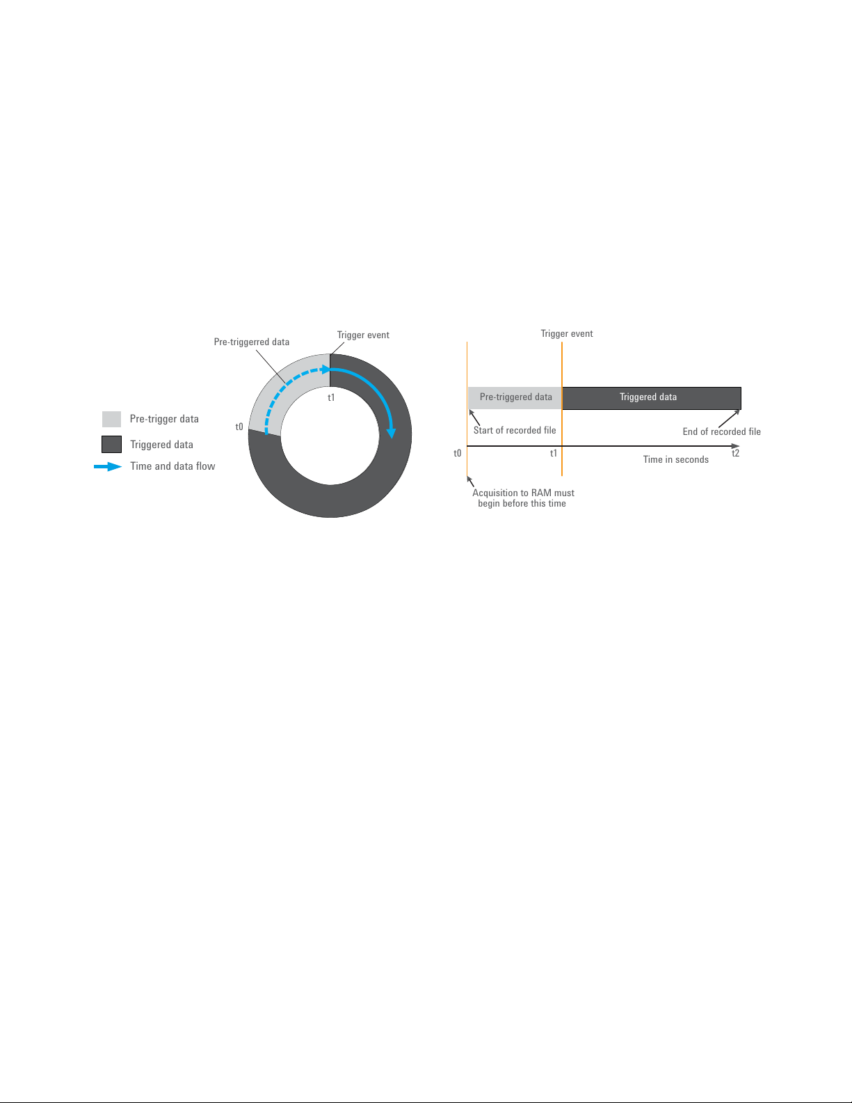
A key feature of gapless recording is its ability to use large quantities of system
RAM for pre-trigger data (Figure 8). Pre-triggered data provides engineers with
access to signal data leading up to a specic trigger event.
When pre-triggered data is requested, the size of the pre-trigger allocation is
related to the amount of available free RAM. Increasing the PC controller RAM
allows for longer pre-triggered acquisitions. The wider the bandwidth captured,
the more memory is required for the same acquisition time. As an example,
a 125-MSa/s complex sample rate provides a measurement bandwidth of
100 MHz.
Circular RAM buffer Recorded file
Figure 8. A useful and powerful feature of a recording solution is the ability to use PC controller RA M
for acquisition. A 64-bit operating system is required to use more than roughly 4 GB of RAM. In this
system, any free memory in the PC controller can be used as a RAM buf fer. When using a RAID array,
a relatively small buf fer is sufcient (e.g., a few hundred MB).
In addition to pre-triggering, another useful feature of the M9392A wideband
recording solution is its ability to generate a Windows® time stamp for
recorded data so it can be mapped to an absolute time. This allows engineers
to associate the time of an interference event with matching physical data,
and correlate data from geographically displaced receivers. The M9392A
recording solution’s trigger simultaneously generates the time stamp and
initiates recording.
9
Page 10
A Viable Recording
Solution (continued)
Dual-channel recording
In a single-channel recording system it can be very dif cult to trigger on only
the desired signal. As a result, more data is usually recorded than required to
ensure the interference event is captured. This additional data takes time and
resources to process.
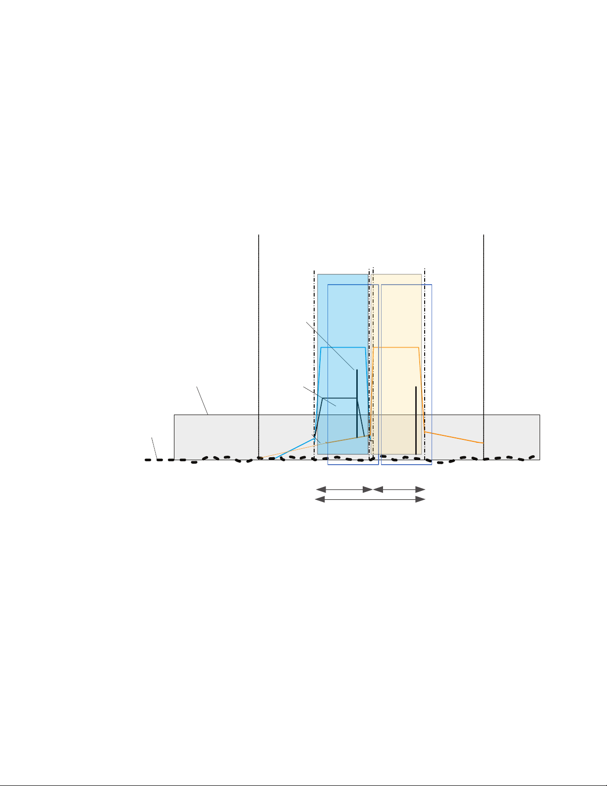
Keysight’s two-channel wide bandwidth RF recording system overcomes this
limitation with a more discretionary triggering capability (Figure 9). With its
independently tunable, dual-channel recording, signals can be acquired and
triggered on one channel, while being recorded on the other. The trigger channel can be any frequency and bandwidth. This allows the engineer to trigger of f
of specic signals and not just any arbitrary signal within the 100-MHz recording bandwidth.
In bandOut of band
In
channel
Out of
channel
Noise floor
Broad band
noise
generator
Strong
VSA
CH 1
VSA
CH 2
CW
carrier
In band
transmitter
Up to 100 MHz BWUp to 100 MHz
BW
Use the 2 channel
VSA to measure these
simultaneously
Figure 9. In this example of a two-channel recording, each channel is independently tunable and can
acquire different amounts of data at a different frequency or bandwidth. Here, both channels are set
to recording mode.
For instance, if a magnitude trigger is set in a full 100-MHz bandwidth, any
signal greater than the threshold (even signals we don’t want to trigger off)
will initiate a recording. In a crowded spectrum, this mechanism leads to false
triggering of recordings in a single-channel recording system. Keysight’s dualchannel technique, although not perfect, of fers a much more robust solution. It
reduces the likelihood of false triggering and provides an innate ability to record
just the data that’s needed. By enabling more ef cient discovery of the signals
in the RF environment, such discretionary triggering saves a great deal of time
and also helps the engineer more effectively solve interference problems.
10
Page 11
A Viable Recording
Solution (continued)
Signal analysis software
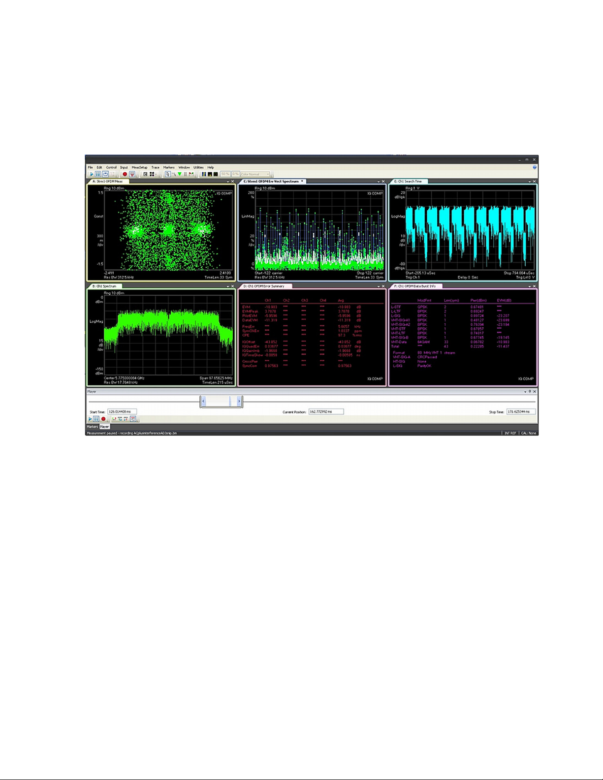
A key benet of the M9392A is that it creates streaming les directly compatible with the 89600 VSA software (Figure 10). This software provides deep
analysis of select interference events or signals discovered during the search
for interferers. Combining the M9392A modular hardware with the 89600 VSA
simplies and reduces the time to nd target signals-of-interest. It also speeds
up the process of analyzing and xing problems.
Figure 10. With the 89600 VSA, engineers get a thorough analysis of selected data obtained during
the gapless recording process.
11
Page 12
Understanding RF
Interference
High power Tx
Fundamental
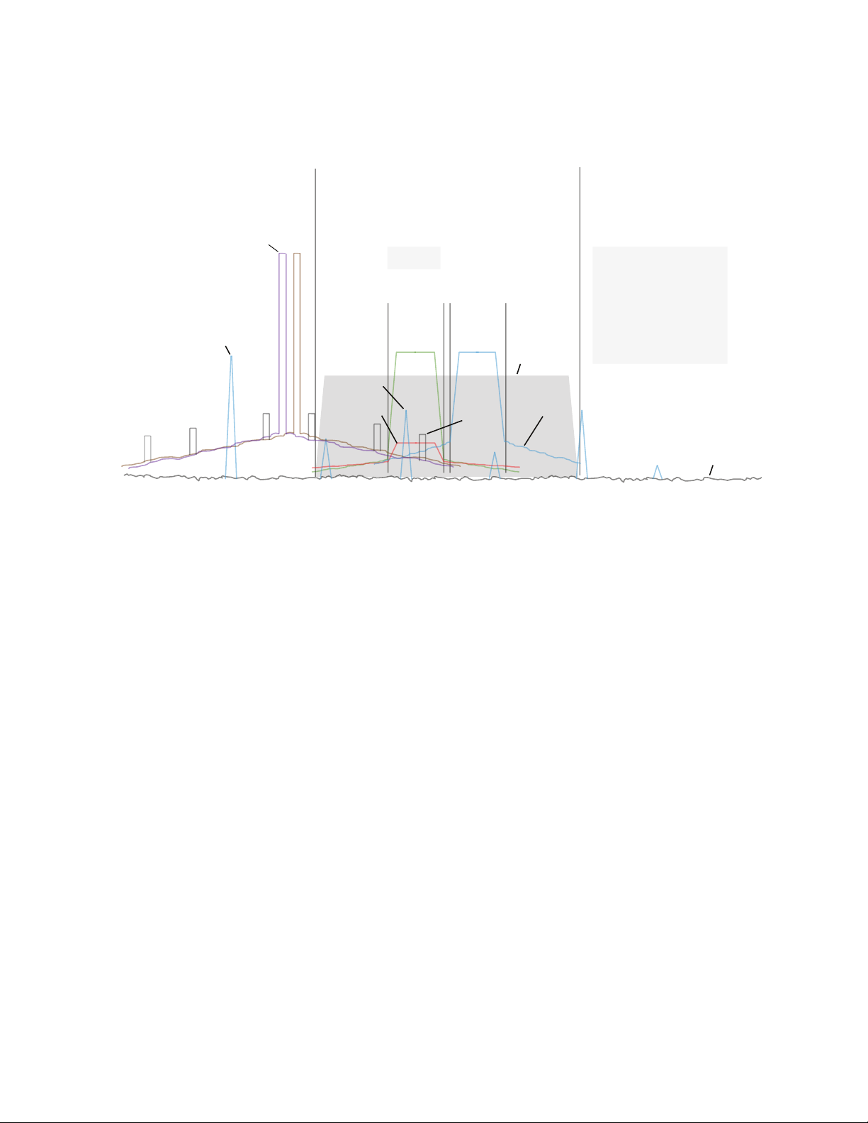
To better understand why RF interference is so complicated and dif cult to
track down, consider the image in Figure 11, which shows the desired channel where the victim receiver operates. It is assumed that the channel is well
designed, possessing both good sensitivity and selectivity.
In-bandOut-of-band
Harmonic
Co-channel
Victim
In
channel
Out of
channel
Intermodulation
Jammer
Adjacent
channel
Culprits
– Co -channel
– Adjacent channel
– PIM and Rx De
– Harmonics/spurs
– Deliberate jamming
-
sense
Noise floor
Figure 11. Different forms of interference are shown here, along with how various types of interferers
can impact a victim receiver.
As the gure illustrates, interference exists as either in-band or out-of-band.
In-band interference, in-channel or out-of-channel, is an undesired transmis-
sion from a different communication system or from a radiator that falls inside
the operating bandwidth of the victim’s system. This type of interference passes
through the receiver’s channel lter and if the interference amplitude is large
relative to the desired signal, the desired signal is corrupted.
Other forms of in-band interference include co-channel interference and
adjacent channel interference. Co-channel interference occurs when another
radio operates in the same occupied spectrum as the victim. While it is one of
the most common culprits in the cellular industry due to frequency reuse plans,
military systems can also suf fer the same fate.
Adjacent channel interference results when a transmission at the desired frequency channel produces unwanted energy in other channels. A fairly common
type of interference, it is primarily created by energy splatter out of the assigned frequency channel and into the surrounding upper and lower channels.
This energy splatter is often referred to as intermodulation distortion or spec-
tral re-growth, and is created by the nonlinear effects in the radio transmitter’s
high-power ampliers.
One form of interference that is often difcult to troubleshoot is out-of-band
transmissions, such as Passive Intermodulation (PIM) distortion or RF overload.
PIM is caused by high-power transmitters in the vicinity of the victim receiver.
Here, dissimilar metals near large broadcast antennas can act as nonlinear
junctions (e.g., diodes) to create intermodulation products that fall in the passband of the victim receiver.
12
Page 13

Understanding RF
Interference (continued)
RF overload also occurs when operating near high-power radiators. In this case,
electromagnetic energy from the radiator couples into the victim’s antenna and
RF front-end, regardless of frequency, desensitizing the victim’s receiver. In
areas of high RF congestion, such as shipboard environments, this coupling is
often strong enough to physically destroy RF front-end circuitry. Harmonics and
spurs from out-of-band transmitters can also be problematic, since they block
the victim’s ability to receive normal transmissions.
Thus far, the types of interference discussed have all been forms of unintentional jamming of a victim receiver. However, EW operators and engineers must also
deal with intentional jamming such as barrage jamming, which transmits a band
of energy intended to saturate the victim’s RF front-end, degrading its ability to
receive intended messages (Figure 11).
In addition to having to consider all the different types of RF interference, a fur-
ther complication in the process of detecting and testing for RF interference is
the temporal nature of the interfering waveforms. While Figure 11 clearly shows
these waveforms as steady-state, the time and intensity of each interferer is
unpredictable, which makes isolating the interferer a real challenge.
13
Page 14
Resolving RF
Interference Problems
with a Structured
Process
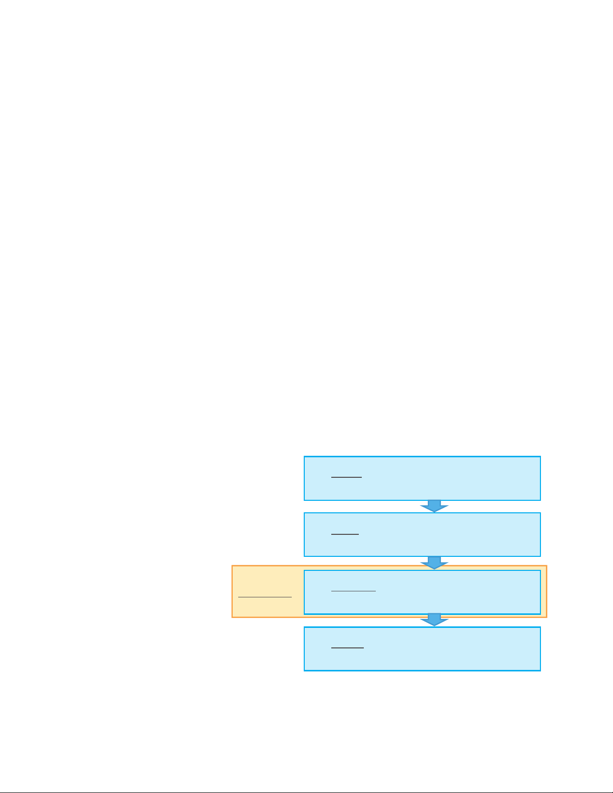
Even with gapless capture, the task of resolving RF interference problems is
challenging enough that it deserves to be guided by a systematic process. One
such process that builds knowledge of the RF environment, while allowing engi-
neers to record information in the frequency band over a long duration is shown
in Figure 12. It includes the following steps:
Step 1. Capture
In this step, data is acquired using long-duration recording to ensure the capture of the interferer event. Long duration is required because the signals in the
RF environment are often long duration. Also, RF environments change over
time and typically have crowded spectrums. Moreover, the increasing band-
width of modern communication signals means the noise spectrum is wider and
interactions are often intermittent, subtle or transient.
Step 2. Search
Once acquired, a recording is played back and analyzed in the lab, as necessary, to extract information about the interferer. Signal search tools, which can
perform automatic searches based on many different criteria, are highly recommended for nding interferers in very large records. The search results in a list
of signals from the data record that matches the criteria. Once found, these
signals can be clipped out and played back using a signal analysis application.
Step 3. Re-Capture Data
Once the engineer has a better understanding of the problem scenario or what
the potential interferers are, it may be necessary to capture more specic recordings. In this optional step, the engineer uses that knowledge of the interferer to trigger additional recordings with better signal-to-noise ratio. These
recordings can focus on a specic reaction of a victim receiver to a specic
interferer. Here, a dual-channel recording system may prove especially useful
as it can be congured to use one of its channels to trigger the recording.
Step 4. Analyze
Finally, the engineer can uncover the effect of the interferer using analysis
software.
1. Capture : Long duration recordings ensure the Culprit
event is captured
2. Search
Optional Step
Figure 12. Acquiring knowledge of the RF environment is easy using this structured owchart.
3. Re
4. Analyze
: Zoom in with search tools to find the Culprit
interferer
: Use knowledge of Culprit to trigger -Capture
additional recording(s) with better SNR
: Uncover the effect of the Culprit interferer
using VSA software
Utilizing the steps in this process, engineers can efciently use RF recording to
record, search and analyze target signals in complex RF environments.
14
Page 15
Resolving RF
Interference Problems
with a Structured
Process (continued)
Application examples
The M9392A wideband multi-channel recording solution allows engineers
to run a complete set of scenarios one time and then conveniently analyze
them ofine. It can be applied to solve a range of issues, including: general
wide bandwidth RF recording, simultaneous measurement of RF and IF signal
components, recording of frequency hop events in military communications and
EW, the response to an EW stimulus or EW scenario recording, and recording of
events that are difcult to trigger or can easily be easily false triggered. Some
specic application examples are:
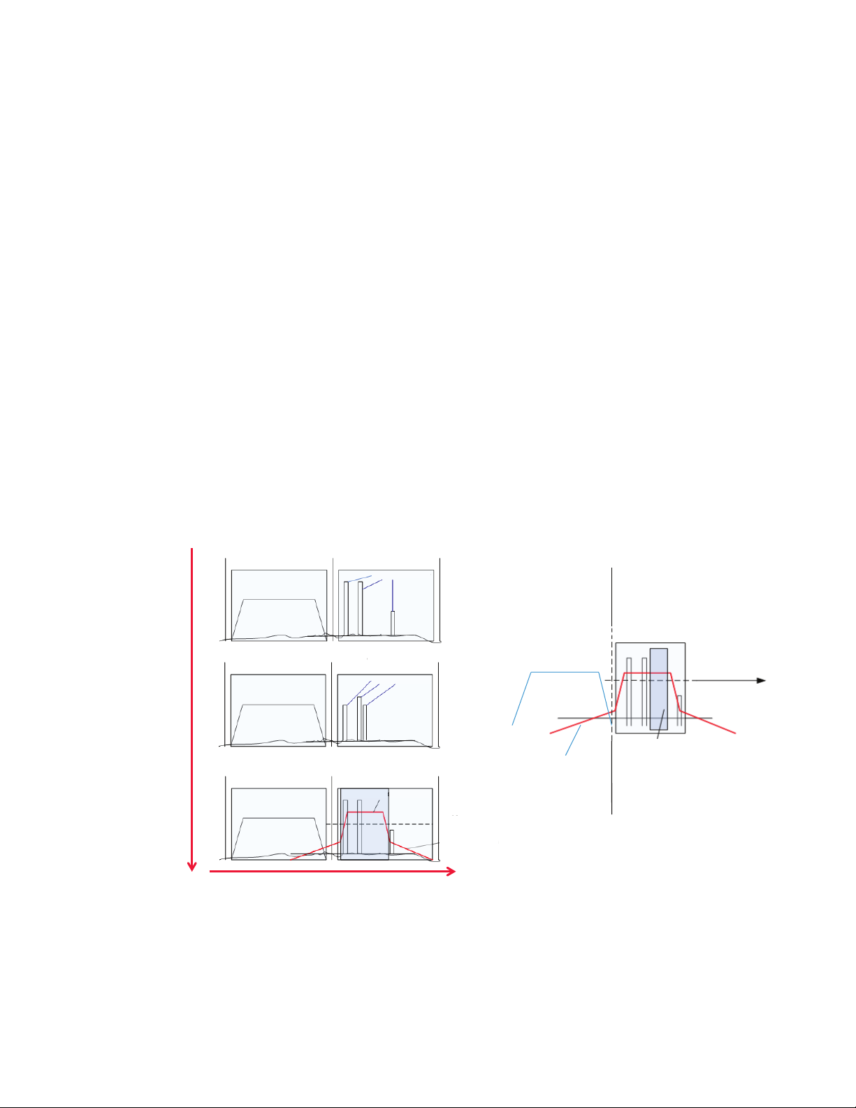
Adjacent Channel Interference
In Figure 13, the victim receiver in channel 1 suffers a severe degradation in
RF performance when an adjacent channel is transmitting. Spectral leakage
is suspected based on signals found in a previous long duration capture. That
recording provided a decent picture of the signal that appears to be causing
the degradation. Given this information, one channel is assigned to measure the
out-of-band signal, congured with a specic frequency, bandwidth and magnitude. This allows the engineer to trigger, with minimal risk of a false trigger,
the recording of the victim channel when the interferer interference is present.
Since this allows us to make a short, targeted recording it is easy to nd, then
clip out data and analyze it using the 89600 VSA software. A recording of both
channels would provide evidence of the cause and effect and is useful when
mitigating steps need to be taken against whoever is transmitting the interfering signal.
Time
In-band
Out of band
Spurious carriers
Ch1
In-band
Out of band
Spurious carriers
Ch1 Ch2
In-band
Out of band
Transient burst
Victim Culprit
Figure 13. In this example, an intermittent out-of-band signal leaks into the victim channel.
Ch2
Trigger level
Spectral regrowth
Record
channel
Ch1 Ch2
In-band
Victim
Record spectral
regrowth in CH1
Trigger
channel
Out of band
Trigger level
Trigger
bandwidth
Trigger recording in
Ch1 from specific
signal in Ch2
15
Page 16
Resolving RF
Record in CH1 with pre-trigger
User monitors for signal in Ch2
Ch1
Ch2
Record channel Trigger channel
Both receivers same band
Pre-triggered data
Trigger event
Controller
RAM
buffer
Application examples (continued)
Interference Problems
with a Structured
Process (continued)
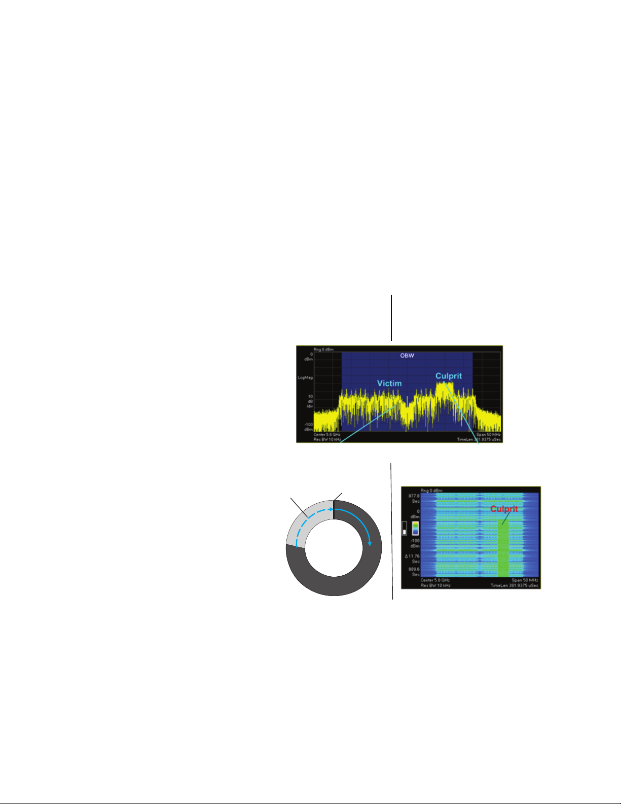
In-Band Interference Test
In Figure 14, an interferer is suspected of intermittently degrading the victim
receiver. In this case, one channel is setup to record. The engineer monitors the
active channel using the other receiver. A spectrograph or persistent spectrum can be used to identify the interferer when it appears. Since the recording channel can be congured with many seconds of pre-trigger, it is possible
to manually trigger the recording channel and still capture a recording of the
interference just as it appeared. This technique can be used when signal clutter
is likely to cause false triggering of recordings.
Note that because the monitoring channel is using a normal signal analyzer
acquisition mode, there will be gaps in its recorded data. However, this will only
be a problem if the interferer signal appears for very short durations (e.g., less
than 100 milliseconds). The benet of this mode is that the engineer can use
specic signal events to make the triggering decision.
Figure 14. For in-band inter ference tes t, the engineer can use user-operated trigger on one channel,
while recording on the other.
16
Page 17
Resolving RF
Occupied BW
Occupied BW
Occupied BW
Occupied BW
Interference
Interference
Cognitive
Radio band
Time
Frequency
Application examples (continued)
Interference Problems
with a Structured
Process (continued)
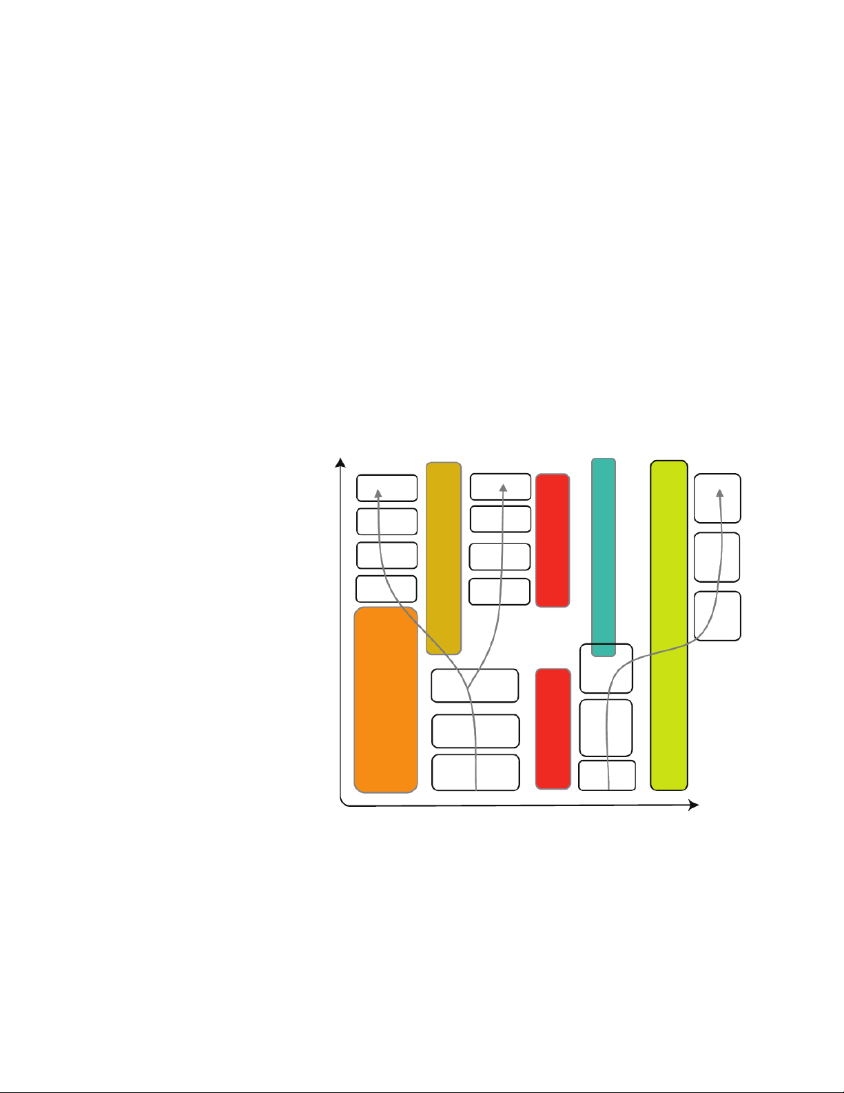
Cognitive-Radio Dynamic Spectrum Access (DSA) Validation
A goal of dynamic spectrum access is to increase spectrum utilization without
causing interference. Consider a scenario in which the cognitive radio starts
transmitting with some OFDMA carrier allocation (frequency) and at some
point in time detects an interferer. To maintain its data throughput with another
radio or base station, the cognitive radio may alter its subcarrier allocation to
utilize other whitespace available within the radio’s policy. In this case, a wide
bandwidth recording capability is useful for measuring multiple radio channels
simultaneously.
Consider the cognitive radio application in Figure 15. When testing the frequen-
cy hop algorithms or responding to RF channel performance changes by modi-
fying the signal constellation it is useful to record just the signal transitions. The
frequency bands used by the cognitive radio are highlighted by the arrows run-
ning through the gure’s white rectangular blocks. When an interferer appears
in band, the response of the radio to the interferer is recorded. Likewise, when a
wireless channel deteriorates, the radio’s response is recorded. These types of
measurements can be easily handled by a multi-channel recording system.
Figure 15. In cognitive radio applications, a multi-channel recording system can be used to trigger the
recording from a specic inter ference event and record that all transmission bands and channel hops
are correct.
17
Page 18
Resolving RF
Record in CH1 with pre-trigger
User monitors for signal in Ch2
WLAN
access point
RADAR
pulse
Pre-triggered data
Trigger event
Controller RAM
buffer
Application examples (continued)
Interference Problems
with a Structured
Process (continued)
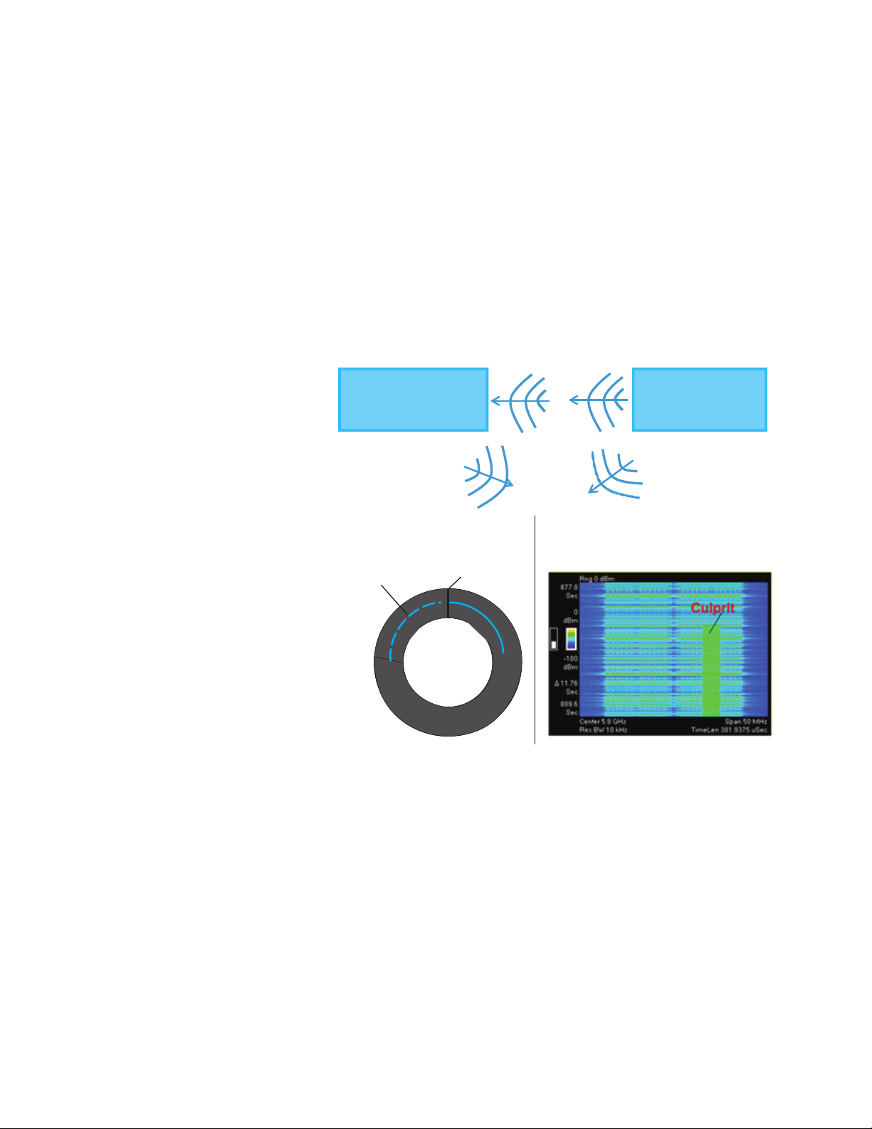
Dynamic Frequency Selection (DFS)/RADAR Detection
Consider the scenario in Figure 16. DFS is a communications technique whereby
transmitters actively ‘listen’ to the RF environment and dynamically choose transmit channels based on the environment characteristics. The goal for transmitters
employing DFS is to transmit on the ‘best’ channel (typically the channel with the
lowest level of detectable RF energy).
WLAN 802.11 access points operating in the 5-GHz band are required to detect
and then avoid military and weather RADARS sharing the same frequency
channels. When the 802.11 access point detects a RADAR pulse it must stop
transmitting and nd an alternative channel to transmit on. With a wideband
multi-channel recording solution, RADAR proles can be run and RF data recorded. The data can then be analyzed of ine.
Figure 16. A wideband multi-channel recording solution is well suited for DFS and RA DAR detection.
When very large recordings of captured data must be searched for culprits, a
powerful signal analysis tool like Spectro-X from Keysight’s solutions partner,
X-COM Systems, may prove especially helpful. Using the software, searches
can be made for carriers, standards based communications signals or custom searches based on any unknown signal found in the record. Some of the
software’s key capabilities include the ability to pre-process large data sets
and locate suspect signals. Spectro-X includes search engines to identify and
“ngerprint” waveforms, as well as a “clip and save” capability for replay into
the 89600 vector signal analysis (VSA) software.
For more information on Spectro-X and other X-COM solutions, please see Application Note 5991-0768EN, “Streaming, Analysis and Playback of RF Interference Signals in Aerospace and Defense Applications.”
18
Page 19

Conclusion
Resolving RF interference problems in complex RF environments is challenging.
With gapless recording; however, engineers can now measure data continuously over long durations and ensure the capture of all RF events of interest when
they occur. A wideband recording system modied for gapless capture, especially one that’s dual channel, can be very effective in characterizing system
interference in RF environments. Utilizing the recording system in a systematic,
structured ow provides an efcient way to nd, record and analyze target
signals. Coupling the system with powerful search tools reduces the burden of
searching long recordings for interferer signals, while signal analysis sof tware
provides engineers with key insight into the characteristics of the inter ferer and
its ef fects on the victim signal in select data obtained during gapless recording.
Such functionality is crucial in today’s commercial wireless and EW applications
where interference-related issues are highly problematic.
19
Page 20

20 | Keysight | Using RF Recording Techniques to Resolve Interference Problems - Application Note
myKeysight
www.keysight.com/find/mykeysight
A personalized view into the information most relevant to you.
www.axiestandard.org
AdvancedTCA® Extensions for Instrumentation and Test (AXIe) is an
open standard that extends the AdvancedTCA for general purpose and
semiconductor test. Keysight is a founding member of the AXIe consortium.
www.lxistandard.org
LAN eXtensions for Instruments puts the power of Ethernet and the
Web inside your test systems. Keysight is a founding member of the LXI
consortium.
www.pxisa.org
PCI eXtensions for Instrumentation (PXI) modular instrumentation delivers a
rugged, PC-based high-performance measurement and automation system.
Three-Year Warranty
www.keysight.com/find/ThreeYearWarranty
Keysight’s commitment to superior product quality and lower total cost
of ownership. The only test and measurement company with three-year
warranty standard on all instruments, worldwide.
Keysight Assurance Plans
www.keysight.com/find/AssurancePlans
Up to five years of protection and no budgetary surprises to ensure your
instruments are operating to specification so you can rely on accurate
measurements.
www.keysight.com/quality
Keysight Technologies, Inc.
DEKRA Certified ISO 9001:2008
Quality Management System
Keysight Channel Partners
www.keysight.com/find/channelpartners
Get the best of both worlds: Keysight’s measurement expertise and product
breadth, combined with channel partner convenience.
ATCA®, AdvancedTCA®, and the ATCA logo are registered US trademarks of the PCI
Industrial Computer Manufacturers Group.
PCI-SIG®, PCIe® and the PCI Express® are US registered trademarks and/or service marks
of PCI-SIG.
Windows, Windows NT, MS Windows, and Windows Vista are trademarks or registered
trademarks of Microsoft Corporation in the United States and/or other countries.
For more information on Keysight
Technologies’ products, applications or
services, please contact your local Keysight
office. The complete list is available at:
www.keysight.com/find/contactus
Americas
Canada (877) 894 4414
Brazil 55 11 3351 7010
Mexico 001 800 254 2440
United States (800) 829 4444
Asia Pacic
Australia 1 800 629 485
China 800 810 0189
Hong Kong 800 938 693
India 1 800 112 929
Japan 0120 (421) 345
Korea 080 769 0800
Malaysia 1 800 888 848
Singapore 1 800 375 8100
Taiwan 0800 047 866
Other AP Countries (65) 6375 8100
Europe & Middle East
Austria 0800 001122
Belgium 0800 58580
Finland 0800 523252
France 0805 980333
Germany 0800 6270999
Ireland 1800 832700
Israel 1 809 343051
Italy 800 599100
Luxembourg +32 800 58580
Netherlands 0800 0233200
Russia 8800 5009286
Spain 0800 000154
Sweden 0200 882255
Switzerland 0800 805353
Opt. 1 (DE)
Opt. 2 (FR)
Opt. 3 (IT)
United Kingdom 0800 0260637
For other unlisted countries:
www.keysight.com/find/contactus
(BP-06-23-14)
www.keysight.com/find/ad
This information is subject to change without notice.
© Keysight Technologies, 2013–2014
Published in USA, August 3, 2014
5991-2059EN
www.keysight.com
 Loading...