


HEWLETT
PACKARD
OPERATING AND PROGRAMMlNC MANUAL
5334A
UNIVERSAL COUNTER
SERIAL PREFIX: 2245A
This manual applies to Serial Prefix 2245A, unless
accompanied by a Manual Change Sheet indicating
otherwise.
IMPORTANT NOTICE
This Operating Manual is a duplication of the first
three sections of the Operating and Service Manual.
All reference within the text to appendices or “the
end of the manual” refer to the end of the Ooeratine:
and Service Manual.
I

COPYRIGHT AND DISCLAIMER NOTICE
Copyright - Agilent Technologies, Inc. Reproduced with the permission of Agilent
Technologies Inc. Agilent Technologies, Inc. makes no warranty of any kind with regard
to this material including, but not limited to, the implied warranties of merchantability
and fitness for a particular purpose. Agilent Technologies, Inc. is not liable for errors
contained herein or for incidental or consequential damages in connection with the
furnishing, performance, or use of this material or data.

MANUAL UPDATING CHANGES
CHANGE DATE:,March
18, 1985
* * * * WABUAL IDENTIFICATION * * * *
* r
* * * * MANUAL UPDATING COVERAGE* *,* *
l
* This supplement adapts your manual *
* to instruments with serial numbers *
* prefixed through 2510.
*
****I************f*t
* Instrument:
s
*
*
*
*
*
*
* Manual Part No:
* Manual Microfiche:
* Manual Print Date:
*********lt*lX**Xf*
HP 53348
UNIVERSAL COUNTER *
OPERATING b PROGRAMMING*
MANUAL
05~34-90001
JUNE 1983 *
ABOUT THIS SUPPLEMENT
The information In this supplement is provided to correct manual errora and to
adapt the manual to instruments containing changes after the manual print date.
Change and correction information in this supplement is itemized by page
numbers corresponding to the original manual pages. The pages in this supple-
ment are organized in numerical order by manual page number,
*
*
*
*
*
Manual updating supplements are revised as often as necessary to keep manuals
as accurate as possible. Hewlett-Packard recommends that y$~ periodically
request the Latest edition of this supplement. Free copies are available from
all HP offices. When requesting copies quote the model number, print date, and
part number listed at the top of this page.
How M USE THxcs SUPPLEMENT
Insert this title
Perform all,changes specified
page in front of the,title page in your manual.
for ‘,!A11 Serials*, and all changes through the
Series Prefix of your instrument or board.
Insert any complete replacement pages
provided into your manual in the proper
location.
If your manual has been updated according to the last edition of this supplement, you need only perform those changes pertaining to the new Series prefix.
See List of Effective Pages on the reverse side of this page. New information
affecting “All Serials” will be indicated by a
v#” in front of the page number.
HEWLETT
PACKARID

**********Yt*************************~****~**~***~**************~~~~~~~*****~**
LIST OF EFFECTIVE PAGES
l
SERIAL PREFIX OR
SERIAL NUMBER
PAGES
**************************************~~******~~*~~*~~~~*********~~~~~*~~~~~**~
All Serials
23506
24228
2426A
1-2, 1-4, 1-7. 3-87. 3-100
No change in operation or specifications.
No change in operation ot- specifications,
No change in operation or specifications.
I
-----___-__f-llrfltl_I_llfl_rf__________---~~-----------------------~---------- I
~5334A~2422=~5099,15687,15954/2426A.15951,16309/2510A~16737

______f--l___------f-------------~~-------------~"-----------------------------
MANUAL CHANGES,
SERIAL PREFIX OR
SERIES NUMBER
Page 1-2, Table l-1. Model 53348 Specifications:
All Serials .>Change PERIOD A, Range from IO ns to 103 'S:tO
10 ns to 103 s, single shot
(10 ns to IO s for 100 GATE AVERAGE)
>Change TIME INTERVAL A to B, Range from -1 ns'to 103 s
to -1 ns to 103 s, single shot
(-1 ns to 10 s for 100 GATE AVERAGE)
Page l-4, Table l-l. Mode1 5334A Specifications:
A11 Serials DATA OUTPUT, High Speed Output Mode:
>Change Rate from 150 readings/second to 140 readings/second.
Mom
5334A
(05334-90001)
CHANGES.
Page l-7, Table
All Serials
l-3.
Accessories Available:
Rack Mounting Adaptor Kits:
>Change Rack Mount with Handles attached from 5020-8874 to
5061-2069.
>Chan$e Rack Mount with Handles removed from 5020-8862 to
5061-0074.
2510A
Rack Mounting Adaptor Kits:
>Change Rack Mount with Handles attached from 5061-2069 to
5061-9769 (Metric).
>Change Rack Mount with Handles removed from 5061-0074 to
5061-9674 (Metric).
This changes 5334A cabinet parts and hardware from
inch to metric.
Page 3-87. Operating & Programming:
All Serials Paragraph 3-385:
>Change
'I*.. 140 measurements per second."
'I... 150 measurements per second." to
NOTE

,,. \>
MANUALCHANGES ;ODEL, :5334A, (05334-90001)
SERIAL PREFIX OR
Page 3-100. Example 10. Translating,High Speed Data Outputs:
All Serials
:>Change tt,*.
150 readingsYto 'I... 140'readings" in two
places in the first paragraph.
Example 10 Program Listing:
>Change "(150)** to "(140" in line 20.
>Change "[12081 to [I1283 in line 30.
>Change "149" to rr139w in lines 110 and 310.
Example 10 Program Comments:
>Change tr15017 to "140" in lines 20, 110, and 310.
>Change rr150w Co *w140w and "1208" to rt1128w in line 30.

Model 5334A
Table of Contents
TABLE OF CONTENTS
Title
GENERAL INFORMATION ........................................... l-l
I-1. Introduction ................................................. 1-l
l-3. Manual Summary ............................................
1.6. Specifications ................................................ 1-l
l-8. Safety Considerations
I-IO. General ...................................................
l-12. Safety Earth Ground
1.14. Safety Symbols
l-16. Instrument and Manual Identification
l-21. Description ..................................................
1.25. Accessories ..................................................
l-27. Options ..................................................... l-6
INSTALLATION
2-I. Introduction
2-3. Unpacking and Inspection _, 2-1
2-5. Preparation for Use
2-6. Power Requirements
2-8. Line Voltage Selection
2-14.
2-16. Operating Enivornment
2-17. Hewlett-Packard interface Bus
2-w HP-16 Interconnections
2-20. Cable Length Restrictions _,
2-22. HP 5334A HP-16 Address
2-24. HP-IB Descriptions
2.26. Storage and Shipment
2-27. Environment ............................................... 2-5
2-30.
2-31. original Packaging
2-33. Other Packaging ......................................... 2-5
Power Cable ...............................................
Packaging .................................................
..................................................... 2-1
................................................. 2-1
......................................... l-l
........................................ 1-5
............................................. 1-5
...........................
........................................... 2-1
....................................... 2-1
...................................... 2-1
..................................... 2-2
.................................
.....................................
.................................... 2-3
.........................................
........................................
....................................... 2-5
Page
l-l
l-l
1-6
1-7
I-7
2-2
2-3
2-3
2-3
2-5
2-5
2-5
ii
III
OPERATION AND PROGRAMMING
3-I.
3-4.
3-Y.
3-11.
3-13.
3-15.
3-17.
3-23.
3-25.
3-27.
3-30.
3-37.
3-39.
3-41.
3-44.
3-46
3-51.
.................................
3-1

TABLE OF CONTENTS (Continued)
Title
OPERATION AND PROGRAMMING
3-53.
3-55.
3-57.
3-63.
3-66.
3-72.
3-74.
3-77.
3-80.
3-82.
3-85.
3-m
3-91.
3-93.
3-95.
3.104.
3.106.
3-114.
3-117.
3.122.
3-126.
3.128.
3-130.
3.135.
3.137.
3.139.
3.143.
3-145.
3.147.
3.150.
3-152.
3-156.
3.158.
3-160.
3.167.
3-169.
3.173.
3.178.
3-180.
3.182.
3.184.
3-186.
3-180.
3.191.
3-193.
3.195.
3-197.
3-199.
Model 5334A
Table of Contents
iii

TABLE OF CONTENTS
(Continued)
Section
III OPERATION AND PROGRAMMING
Title
3-201.
3.203.
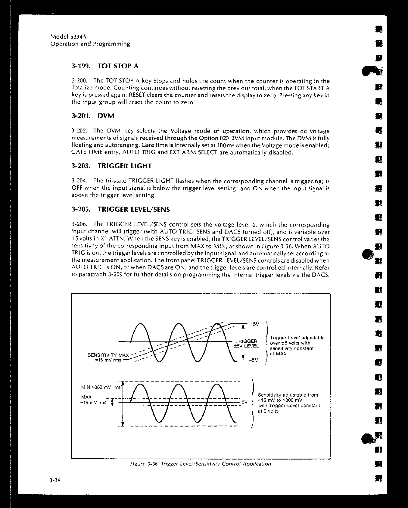
3-205.
3.207.
3-209.
3-214.
3-216.
3.220.
3-222.
3-224.
3-226.
3-228.
3.230.
2-232.
3-235.
3-237.
3-239.
3-241.
3-243.
3-245.
3-247.
3-249.
3-255.
3-257.
3-259.
3-261.
3-263.
3-265.
3-267.
3-269.
3-271.
3-274.
3-277.
3-280.
3-282.
3-286.
3-290.
3-292.
3-294.
3-296.
3-298.
3-299.
3-302.
3.305.
3-307.
3-311.
3-316.
3-318.
DVM ....................................................
Trigger tight
Trigger Level/Sens
Sens .....................................................
Programming Trigger&m Levels via the Front Panel
Returning Trigger/Sens Level Control to the Front
Panel (dACS Off)
Controlling Trigger/Sens Levels Internally IdACS On)
Read Levels ..............................................
Slope ....................................................
AC ......................................................
X10 Attn .................................................
5OfiZ ...................................................
100 kHz Filter A
Auto Trig ................................................
Corn A ..................................................
Ext Arm Select
Input A,B ...............................................
Arm Input ...............................................
Input C (Option 030)
DVM (Option 020)
Front Panel Display and Annunciators
Display Hysteresis
Rear Panel Features, Controls, and Connectors
AC Power Input Module
Gate Out ................................................
Time Base In/Out
Time Base Ad; ...........................................
Time Base Int/Ext ........................................
HP-IB Interface Connector
Arm Trigger Level
Rear Panel Input Connectors (Option 060)
Operator’s Maintenance
Power-Up/Warm-Up
Operator’s Checks
Power-Up Self-Check
Diagnostic Sequence
Error Indications
Error Examples ...........................................
Detailed Operating Instructions
Introduction
Remote Programming via the HP-IB
Introduction
HP-IB Description
Interface System Terms
Major Interface Functions
Interface Capabilities
Front Panel Interface Status LED’s
Address Selection ......................................
............................................. 3-34
..........................................
........................................... 3-38
...........................................
.............................................
..............................................
Page
3-34
........................................
........ 3-35
...................................... 3-36
..................................... 3-40
....................................... 3-40
...................... 3-40
........................................
............. 3-44
.................................. 3-44
........................................
................................
........................................ 3-45
................. 3-45
....................................
..................................... 3-46
......................................... 3-46
..................................... 3-46
..................................... 3-47
.............................
.........................
........................................ 3-68
.................................
............................... 3-69
..................................... 3-69
........................
3-34
3-35
..... 3-36
3-36
3-37
3-37
3-37
3-37
3-37
3-37
3-38
3-40
3-40
3-40
3-44
3-44
3-44
3-44
3-44
3-45
3-48
3-50
3-52
3-52
3-68
3-68
3-68
3-71
3-71

TABLE OF CONTENTS (Continued)
Model 5334A
Table of Contents
List of Tables
Section
III
Table
me
OPERATION AND PROGRAMMING
3.324. Interface Commands ,.,,,,,,,..............................
3-327.
3.330.
3-336.
3-337.
3-342.
3-344.
3-346.
3-348.
3.350.
3-353.
3-358.
3-371.
3-382.
3.390.
3-395.
3-397. Programming Examples 3-92
Device Independent Commands
Meta Messages .........................................
Meta Message Response
SRQ and Status Byte
Service Request Mask
Device Dependent Commands
Device Command Definitions
Numeric Entry
Programming Commands
Command Group Description ........................... 3-81
Miscellaneous and Special Functions ..................... 3-81
output Formats ........................................ 3-85
High Speed Output Data ................................ 3-86
Error Handling
Preset and Disallowed Conditions ....................... 3-88
....................................
.................................. 3-78
.........................................
......................................... 3-88
........................... 3-73
................................
............................ 3-79
........................... 3-79
................................. 3-81
Page
3-73
3-75
3-77
3-78
3-80
LIST OF TABLES
me
page
l-l.
1-2.
1-3.
3-l.
3-2.
3-3.
3-4.
3-5.
3-6.
3-7.
3-n.
3-9.
3-10.
3-11.
3-12.
3-13.
Model 5334A Specifications
Equipment Supplied
Accessories Available
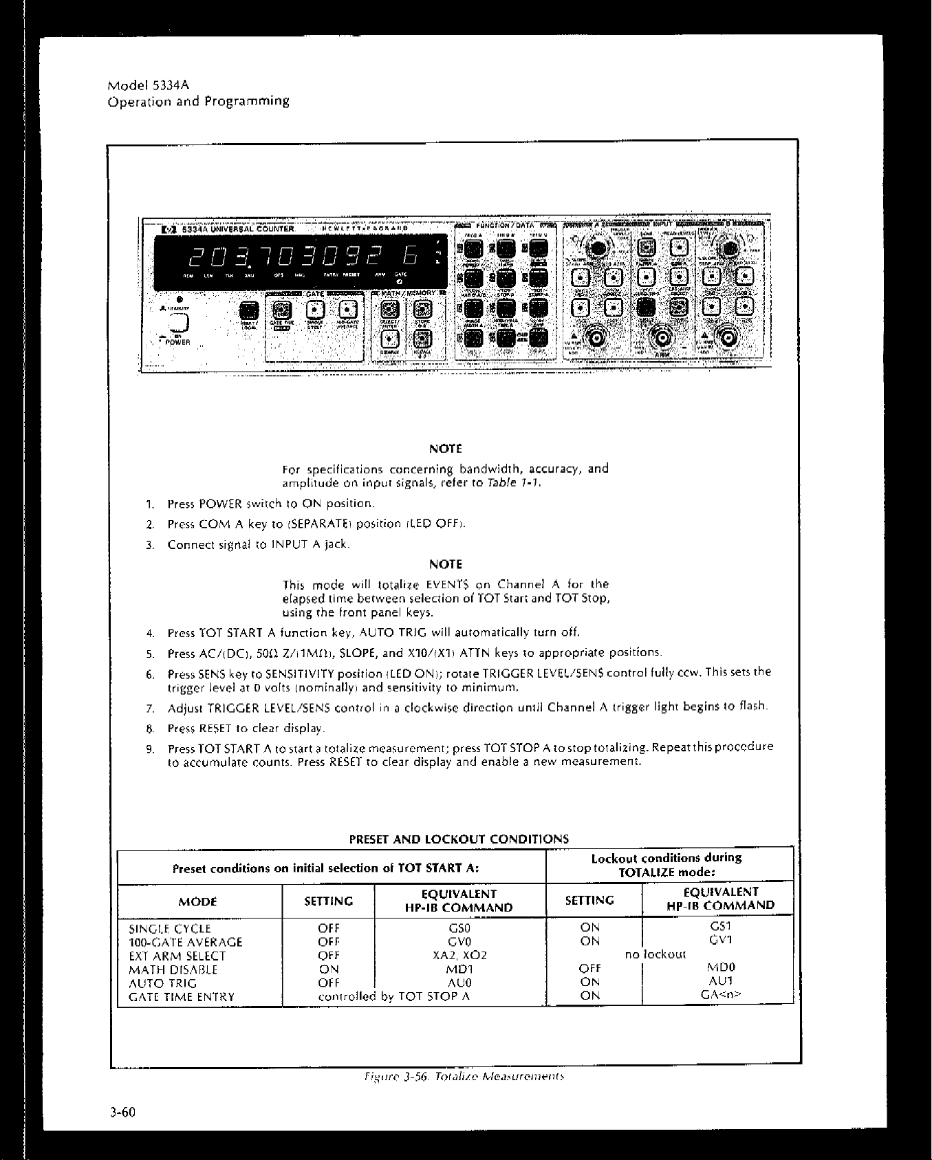
Preset and Lockout Conditons
Trigger/Sensitivity Level Settings
Error Messages ....................................................
Failure Messages ..................................................
5334A HP-IB Interface Functions
5334A Interface Capabilities
Address Selection ..................................................
Device Independent Commands
Meta Messages .................................................... 3-76
Meta Messages and Controller Commands
5334A Status Byte ..................................................
5334A Programming Command Set
HP-It3 Preset and Disallowed Conditions
................................................
.........................................
...............................................
......................................
.................................... 3-35
.................................... 3-70
........................................
....................................
..........................
.................................. 3-83
.............................
I-2
1-7
1-7
3-24
3-49
3-49
3-71
3-73
3-74
3-76
3-78
3-89

LIST OF FIGURES
Figure
1-1.
2-I
2-2.
2-3.
3-I.
3-2.
3-3.
3-4.
3-5.
3-6.
3-7.
3-8.
3-v.
3-10.
3-11.
3-12.
3-13.
3-14.
3-15.
3-16.
3-17.
3-18.
3-19.
3-20.
3-21,
3-22.
3-23.
3-24.
3-25.
3-26.
3-27.
3-20.
3-29.
3-30.
3-31.
3-32.
3-33.
3-34.
3-35.
3-36.
3-37.
3-38.
3-39.
3-40.
3-41.
3-42.
Title
Model 5334A Universal Frequency Counter and Accessories
Voltage Selection with Power Module PC Board
Power Cable HP Part Numbers versus Mains Plugs Available
Hewlett-Packard Interface Bus Connections
Basic Block Diagram of a Reciprocal Counter
Acceptable Peak-to-Peak Amplitude
Insufficient Peak-to-Peak Amplitude
Trigger Level Set Below Midpoint of Input Signal
Varying the Sensitivity Control Changes the Hysteresis Window
AC-DC Coupling
Invalid Input Signal Conditions
Valid Input Signal Conditions
Trigger Level and Actual Trigger Point
Trigger Level Control Shifts Hysteresis Window
Positive and Negative Trigger Points
USC of External Arming to Measure Frequency
Time Interval Measurement
T.I. Averaging Minimum Dead Time
Time Interval Delay Measurement
Pulse Width Measurement
Rise/Fall Time Measurements
Channel A Peak Voltage Measurement Display
5334A Display Indicating a Period Measurement
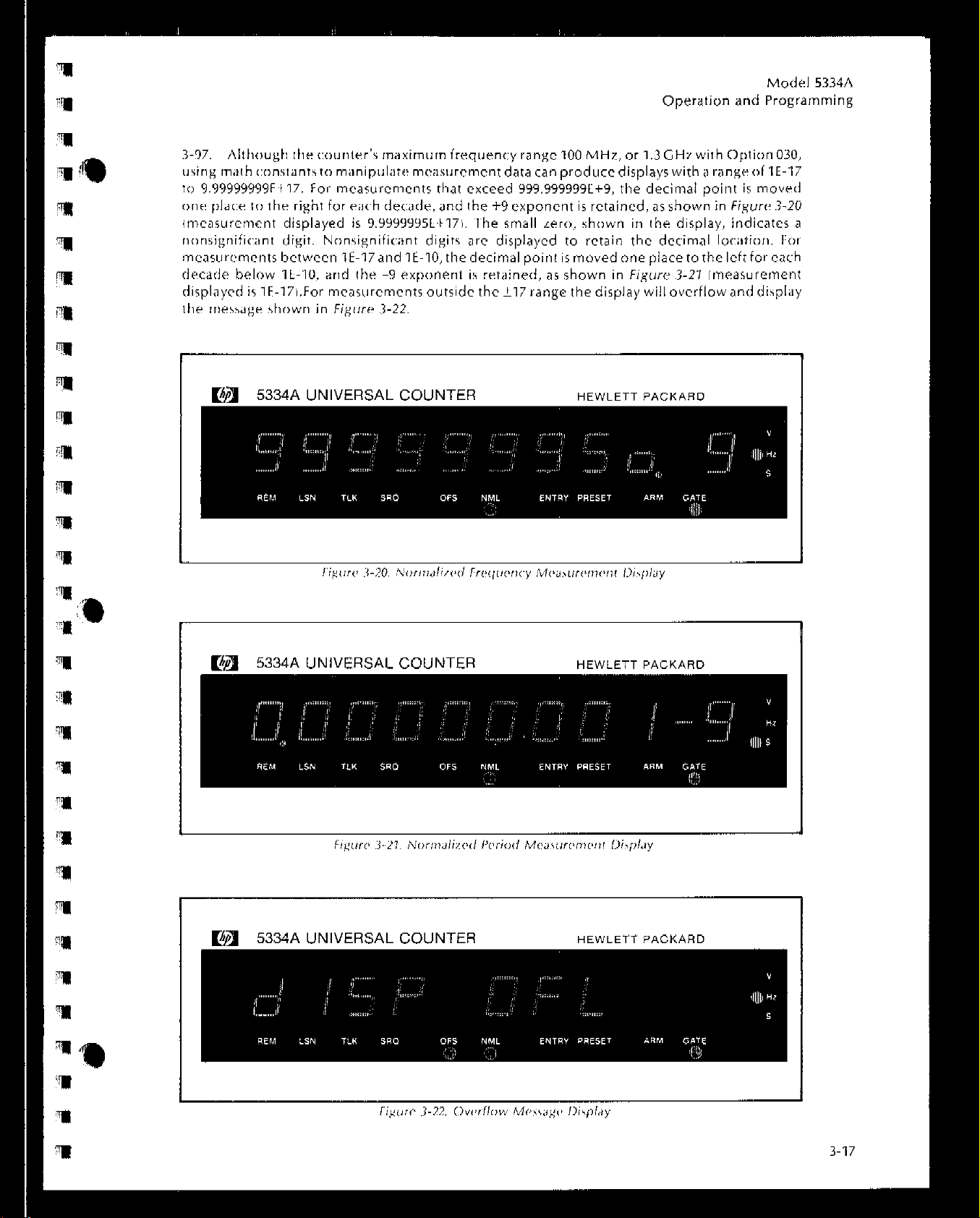
Normalized Frequency Measurement Display
Normalized Period Measurement Display
Overflow Message Display
5334A Front Panel Keyboard
Gate Time Entry Display
External Arm Select Entry Display
Intermediate Power-Up Display
Gate Time Selection Display
Offset Entry Display ................................................
Store Entry Mode Display
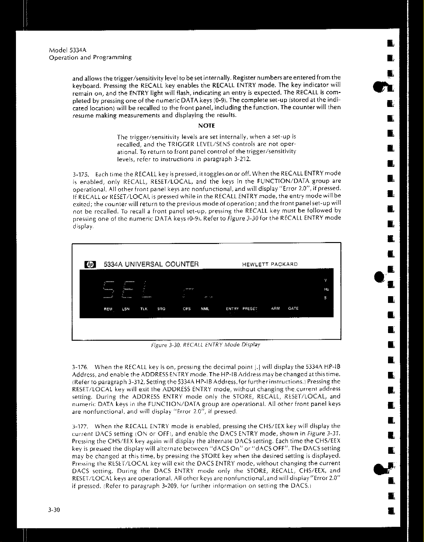
Recall Entry Mode Display
DACS Entry Mode Display
Ratio Measurement Display
Pulse Width Measurement Display
T.I. Measurement Display
.r.l. Delay Measurement Display
Trigger level/Sensitivity Control Application
DACS On Display
Channel B Peak Voltage Measurement Display
Ext Arm Select Entry Mode Display
Arming Modes
Front Panel Display and Annunciators
Front Panel Features, Controls, Indicators, and Connectors
..
.....................................................................................
....................................... 3-7
...
.........................................
....................................... 3-I 5
.........................................
........................................
............................................ 3-20
........................................
..........................................
..........................................
..........................................
........................................ 3-31
..........................................
..................................................
....................................................
................................
................................
............................... 3-7
................................. 3-9
. ....................................
.................................
.................................. 3-13
............................ 3-17
................................... 3-21
.....................................
.................................. 3-32
....................................
..................................
............................... 3-42
.....................
..........................
........................ 3-2
.....................
......................
.......................
....................... 3-16
...................... 3-16
........................ 3-17
.........................
.......................
............ 3-42
Page
.......... 1-O
2-2
.......... 2-3
2-4
3-4
3-4
3-4
....... 3-5
i;;
3-8
3-10
3-l 2
3-13
3-14
3-17
3-18
3-23
3-27
3-28
3-29
3-20
3-31
3-32
3-33
3-34
3-36
3-37
3-38
3-39


Model 5334A
Ccneral Information
_---,,-

Model 5334A
General Information
SECTION I
GENERAL INFORMATION
l-l. INTRODUCTION
l-2. This manual contains the information necessary to install, operate, and program the
Iiewlett-Packard Model 5334A Universal Counter.‘The counter is shown in Figure 7-T with
supplied accessories.
1-3. MANUAL SUMMARY
I-4. This manual is divided into three sections, each covering a particular topic for the operAtion and programming of the HP 5334A. The infprmation contained in each section isdescribed
below.
SECTION I, GENERAL INFORMATION: describes the instrument documented by this
manual and covers instrument identification, options, accessories, specifications, recommended test equipment, and other basic information.
I
I
SECTION II, INSTALLATION: provides information concerning initial inspection, preparation for USE (including address selection for remote operation], and storage and
shipment.
SECTION III, OPERATION AND PROGRAMMING: provides information pertaining to
panel features, operating characteristics, operator’s maintenance, and includesoperator’s
checks, operating instructions for local operation and programming instructions for remote
operation via the Hewlett-Packard Interface Bus.
1.5. AdditionalcopiesofthisManualandoftheHP5334AOperatingandServiceManualcan be
ordered through your nearest Hewlett-Packard Sales and Service Office.
l-6. SPEClFlCATlONS
l-7. Instrument specifications are listed in Table
limits against which the instrument may be tested including typical characteristics asadditional
information for the user.
1-1.
These are the performance standards, or
1-8. SAFETY CONSIDERATIONS
l-9. The 5334A Universal Counter isa Safety Class I instrument (provided with a protective earth
terminal], designed according to international safety standards. Safety information pertinent to
the operation and servicing of this instrument is located in appropriate sections of this manual
including cautions and warnings which must be followed by the user to enwrc safe operation
and keep the instrument in safe condition.
I
l-10.
1.11. This product and related documentation must be reviewed for familiarization with safety
markingsand instructions before operation. Beforeapplyingpower,verifythat the product isset
to match the available line voltage and the correct fuse is installed. Refer to Section II,
Installation.
GENERAL
1-1 I

Model 5334A
General Information
Table 7-7. Model 5334A Soecifications
INPUT CHARACTERISTICS
CHANNEL A and CHANNEL B
Range:
DC coupled: 0 to 100 MHz.
AC coupied: 1 MI>. 30 Hz to 100 MHz
50 II, 1 MHZ to 100 MHZ.
Sensitivity:
15 mV rms sine wave to 20 MHz.
35 mV rms sine wave to 100 MHz.
100 mV peak-to-peak et a minimum pulse width of 5 ns.
Sensitivity can be continuously varied to 150 mV rms.
iNOMINAL using the TRIGGER LEVEUSENS control
1” sensitivity mode. In this mode, trigger levels
are automatically set to 0 V NDMfNAL.
Dynamic Range (Xl):
45 mV to 5 V peak-to-peak, to 20 MHz.
100 mV to 2.5 V peak-to-peak. to 100 MHz.
Signal Operating Range, DC: i-5 V DC (X ATTN).
Trkmer Level:
“”
Range:
Manual (Auto Trigger OFF): Continuously adjustable over t5.1”. displayed in 20 mV steps. In X10,
?51 V displayed in 200 mV steps.
Preset: 0 V NOMINAL in Sensitivity Mode.
Auto Trigger: See Automatic Measurements Section.
Accuracy:
X1: i-30 mV “1% of trigger level reading.
X10: k300 mV 21% of trigger level reading
Coupling: AC or DC, switch selectable.
Trtgger Slope: Independent selection of + or - slope.
Impedance +: 1 MI1 NOMINAL Shunted by 60 pF or 50 II
NOMINAL, switch selectable.
Attenuator:
Manual: Xl or X10 NOMINAL, switch selectable.
Auto: Attenuator automatically switched when in Auto
Trigger mode. See Automatic Measurements Section.
Low Pass Filter: 100 kHz NOMINAL, switchable in or out
of Channel A.
Damage Level:
50 n: 5 v rms.
1 MCI, x1:
0 to 3.5 kHz: 200 ” ,DC
3.5 kHz to 100 kHz: 5 x
>lOO kHz: 5” rms.
1 MCI. X10:
0 to 35 kHz: 200” IDC + peak AC,.
35 ktiz to 100 kHz: 5 X 10⁶ V rms Hz/FREQ.
,100 kHz: 50 V rms.
Common Input: All specifications are the same as for
separate operation except for the following:
Sensitlvlty:
15 mV rms sine wave to 20 MHz.
75 mV rms sine wave to 100 MHz.
ZlOmVpeak-to-peakataminimumpulsewidthof5ns.
oynemic Range x1:
45 mV to 5 V peak-to-peak. to 20 MHz.
210 mV to 2.5 V peak-to-peak. to 100 MHz.
tmpedancet: 500 kn NOMINAL shunted by ~85 pF or
50 II NOMINAL.
+ peak AC).
105” rms Hz/FRED.
EXTERNAL ARM
Front panel ARM input can be used to determine Start
and/or Stop point of a measurement. External Arm can be
used with all measurements except DVM and READ
LEVELS (Trigger Levels and Amplitude Peaks).
Mlnlmum Wldth: 50 ns
Maxlmum TransItion Time: 1 ~5
Sensitivity: 500 mV peak-to-peak.
Signal Operating Range: -5 Vdc to +5 Vdc.
Dynamic Range: 500 mV to 10 V peak-to-peak.
Arm Trigger Level: Adjustable from -4 V to +4 V by rear
pane, control.
Slope: Independent selection of START and STOP ARM
slopes: +, -, or OFF.
Arm Set-up Time: Typically 20 ns for all measurements
except Totalize. Typically 100 ns for Totalize.
tmpedancet: DC Coupled. 1 kn NOMINAL shunted by
60 pF.
Damage Level: _+15 V IDC + peak AC).
FREQUENCY A and FREQUENCY B
Range: ,001 Hz lo 100 MHz.
LSD@:
Resolution:
+ LSD ~ (1.4 X Trigger Error @ + 1 ns rms)
Accuracy: + Resolution i Time Base Error @ X FREO.
4 ns
Gate Time
X FREQ.
Gate Time
X FREO.
PERIOD A
Range: 10 ns to 103 s
LSD-a :
Resolution:
+ LSD + 11.4 X Trigger Error@ + 1 ns rms) x PER
Accuracy: ? Resolution + Time Base Error @ X PER.
4 ns
Gate Time
X PER.
Gate Time
TIME INTERVAL A to B
Range:-, ns to 103 seconds.
LSD@: 1 r&m”
TIME INTERVAL DELAY
Used with Time Interval A to B, a selectable delay can be
inserted between START IChannel A trigger1 and STOP
(Channel B trigger). Electrical inputs during delay are
ignored. Specifications are the same as for Time Interval
A to B.
Delay Range: 1 ms to 99.999 s (1 ms steps).
Delay Accuracy: +I00 fis k 0.05% X DELAY TIME.
RATIO A/B
Range: ,001 Hz to 100 MHz both channels.
LSD 0 : 4 x RATIWFREQ A x fate ~imei.
Resolution:
+ LSD i B Trigger Error @
Gate Time
Accuracy: Same as Resolution.
Specified for higher frequency input connected to
Channel A.
+ Resistance values are measured at DCand capacitance
w,lJe* et 10 MHZ.
‘This is a systematic error due to differential channel
d&w imatchinc! Channel A and Bi which can be elimi-
nateb byprope;measurementtechnique: i.e..numerical
offset or different cable lengths.
“N = the number of gates averaged.
= 1 in Tf A-B.
= 100 using too-gate average.
X RATIO.

Table ‘i-7. Model 5334A Specifications (Continued)
Model 5334A
General Information
TOTALIZE A
Range: 0 to 10’2-1.
LSD Displayed: 1 count of input signal.
Resoluuon: *LSD.
Accuracy: ZkLBO.
AUTOMATIC MEASUREMENTS
These featuresarespecified from 100 Hzto 20 MHz unless
noted. Minimum width at peak of signal: 5 ns.
AUTO ATTENUATION
Enabled simultaneously with Auto Trigger. (Voltage
values are NOMINAL, measured with 50 0 termination).
X10 attenuator enabled when: either peak is greater
than i- 5.1 V OR difference between maximum and
minimum peaks exceeds 5.1 V.
X1 ettenuetor enabled when: maximum and minimum
peak amplitudes are less than ?I 4.6 volts AND difference between maximum and minimum peaks is
less than 4.4 V.
AUTO TRIGGER
DC Coupled: 100 Hz to 100 MHz.
AC CouPled: 1 MO: 100 Hz to 100 MHz
50 ft 1 MHz to 100 MHz.
Minimum Amplitude: 100 mV rms sine wave, 260 mV
peak-to-peak.
Trigger Level Accuracy: ?;30 mV IX ATTN).
For Rise/Fall Time. ?40 mV IX ATTNI.
Auto Trigger is d&led for Totalize, Frequency C
DVM, and Read Trigger Levels.
RISE/FALL TIME A
Flange: 30 ns to 10 ml*.
Mtnimum Amplitude: 500 mV peak-to-peak.
Dynamic Range: 500 mV to 40 V peak-to-peak.
LSD@: 1 ns ilO0 ps using 100 GATE AVERAGE).
Resolution: i LSD i- Start Trigger Error@ i Stop
Trigger Error@ i 1 ns rms.
Accuracy:
+ Resolution ? Trigger Level Timing Error@
t Trigger Level Setting Error at 10% point@
+ Trigger Level Setting Error at 90% point @
i- (Time Base Error@-X Rise/Fall Time1 i- 2 ns.’
Typically within 3% for triangular, trapezoidal. and
pulse waveforms, 1 V to 5 V IX ATTNI peak-to-peak.
PULSE WIDTH A
Range: 5 ns to 10 ms.
LSD@: 1 ns (100 ps using 100 GATE AVERAGE).
Resotuffon: *LSD ? Start Trigger Error @ f Stop Trigger
Error @ + 1 “s rms.
Accuracy:
t Resolution + Trigger Level Timing Error @
2 Trigger level Setting Error@
i (Time Base Error@ X Pulse Widthl.
Typically within 2% for triangular and pulse WaVefOrmS.
1 V to 6 ” (X ATTN) peak-to-peak.
READ PEAK AMPLITUDES
Maximum and minimum peaks of Channel A or Channel B
input are displayed.
Frequency Range: DC, 100 Hz to 20 MHz.
Dynamic Range: 0 V to 40 V peak-to-peak.
Resotutlon: x1: 20 mv. x10: 200 mv.
Accuracy: + Resolution i- 10% of difference between
maximum and minimum peak displayed. t30 mV.
Typically within 3% for a sinewave ,500 mV peak-to-
peak.
MATH
All measurements except for Totalize and Read Levels
(Trigger Levels and Peak Amplitudes) may be operated
upon by MATH functions. Math values are toggled on or
off using the DISABLE key. Offset and Normalize may
be used independently or together as follows:
Display = (Measurement/Normalize) + Offset,
Entry Range: 2 1 x IO-10 to 2 9.99999999999 x
At power-up, Offset = 0 and Normalize = I.
109.
GENERAL
TIME BASE
Standard Cry&t:
Frequency: 10 MHz.
Aging Rate: ~3 X 10-T per month.
Temperature: 6 X 10⁻⁶, 0” to 5O*C, ref. to 250~.
Line “ottage: <I X 10-T for 10% change.
High Stability Crystal: See Option 010.
External Input: Rear panel BNC accepts 10 MHz. 500 mV
to 5 V rms into 1 kIl NOMfNAL shunted by ~20 pF.
Time Base Output: 10 MHz, ,500 mV rms sine wave into
50 Cl via rear panel.
GATE TIME
Range: 1 ms to 99.999 seconds in 1 ms increments.
Automatically set to 300 ms at power up.
LSD: 1 ms.
Resolution: i- LSD.
Accuracy: i1OOps ?(0.05% X GATE TlMEi + up to one
period of input signal.
TIME BETWEEN MEASUREMENTS:
Auto Trigger on: 1 s NOMINAL.
Auto Trigger off: 80 ms NOMINAL.
IOOGATEAVERAGE: IOOgatesaccumulatedandaverage
displayed. This adds an additional digit of resolution. It
can be used with a,, functions except Totalize, DVM, and
Read Levels (Trigger Levels and Amplitude Peaksl.
StNGLE CYCLE: When enabled, one measurement is
taken with each push of RESET key.
MEMORY: Ten measurement set-ups, including trigger
levels, may be stored in memwy and subsequently recalled. When a measurementset-up has been recalled,the
trigger level equals the stored value (trigger level COntlOlS
are inactive). The trigger level can be toggled between the
stored value and front panel trigger level control using
DACS ON/OFF function. With instrument in STBY or AC
power removed, the internal battery will supply the non-
volatile memory for typically 60 days.
RESET: Begins a new measurement cycle, clears front
pane, data entry modes. and error and failure messages.
PRESET: PRESET LED indicates that front panel trigger
level/sensitivity controls are inactive.
GATE OUTPUT: Rear panel BNC drives TTL levels into
1 kn. Level is high while gate is open during all measurements except Totalize, DVM, and Read Levels (Trigger
Levels and Amplitude Peaks).
DISPLAY: g-digit LED display in engineering format plus
onedigitexponent. Rangeisk10-17to?-9.99999999X 10”
OPERATING TEMPERATURE: 0 to 5O’C.
POWER REQUIREMENTS: 47.5 - 440 Hz, 90 - 126.6 V;
47.5 - 66 Hz, 196 - 252 V: 50 VA maximum.
WEIGHT: Net, 5.3 kg (11 Ibs. 12 oz.); Shipping, 6.1 kg
117 Ibs. 12 oz.,.
DI’MENStONS:6~mmHx422mmWX346mmD.(31/2”H
x 16 518” W x 13 516” D). excluding bottom feet and
removable front handles.

Model 5334A
General Information
Table ‘f-1. Model 5334A Soecifications Kontinued)
HEWLETT-PACKARD INTERFACE BUS
PROGRAMMABLE CONTROLS: All front panel controls
and functions, except Option 030 Channel C sensitivity
and power onlstby switch.
TFffGGER
+5.l V in 20 m” steps (X ATTNl.
AWllaCy:
OTHER: Initialize, Transmit Error, High-Speed Output,
DATA OUTPUT:
Normal Operation: format: 19 characters plus CR
High Speed Output Mode: Format: 8 bytes of count
Talk Only Mode: Selected by entering an address of 50.
tNTERFAdE FUNCTIONS: S& AH1 T> TEO L4 LEO SRl
RLl PPO DC1 DTl CO E2
LEVEL:
Xl: K4l mV +_l% of trigger level reading.
X10: i3OO mV +10/o of trigger level reading.
Transmit Calibration Data, Device ID, and SRQ Mask.
and LF:
Rate: Ten readings/second.
data and Inter!,olator Start and StoD co”“&
Rate: 150 readings/second.
Set Channel
A or 6 from -5.1 V
to
LSD Dfspfayed: There is a 9 digit mantissa maXimUm ‘0, the
fro”, pane, display. If tr”nCa,ion I* required the most sIgnificant digits are displayed. Up to a 12 digit mantissa is
_ wailable DYW HP-IS.

Model 5334A
General Information
1-12. SAFETY EARTH GROUND
l-13. An uninterruptiblesafety earth ground must be provided from the main powersourceto
the instrument input
wiring
terminals, power cord, or supplied power cord set.
1-14. SAFETY SYMBOLS
CAUTION
The symbol
panel of the instrument, indicates that the user should refer to
the instruction manual before operating in order to avoid
possible damage to the instrument. Within the manual, information relating to the ATTENTION symbol will be identified with
a A symbol in the margin.
A (ATTENTION), which appears on the front
I-15. The following safety symbols are used on equipment and in manuals:
Instruction manual symbol. The product will be marked with this
symbol when it is necessary for the user to refer to the instruction
manual in order to protect against damage to the instrument.
Indicates dangerous voltage (terminal$ fed from internal or external
source by voltage exceeding 1000 volts must be so marked).
Protective conductor terminal. For protection against electrical shock
in case of a fault. Used with field wiring terminals to indicate the
terminals which must be connected to ground before operating
equipment.
low-noise or noiseless, clear ground (earth) terminal. Used for a
signal common, as well as providing protection against electrical
shock in case of a fault. A terminal marked with the symbol must be
connected to ground in the manner described in the installation
ioperating) manual, and before operating the equipment.
Frame and chassis terminal. A connection to the frame (chassis) of the
equipment which normally includes all exposed metal structuresAlternating current.
Direct current.
Alternating or direct current.
The WARNING signal denotes a hazard. It calls attention to a
procedure, practice, or the like, which, if not correctly performed or
adhered to, could result in personal injury. Do not proceed beyond a
WARNING
sign until the indicated conditions are fully understood
and met.
The CAUTION sign denotes a hazard. It calls attention toan operating
procedure, practice, or the like, which, if not correctly performed or
adhered to, could result in damage to or destruction of part or ail of
the product. Do nor proceed beyond a
CAUTlON
sign until the
indicated conditions are fully understood and met.

Any interruption of the protective (grounding) conductor (inside or
outside the instrument) or disconnecting the protectiveearth terminal
will cause a potential shock that could result in personal injury.
(Grounding one conductor or a two-conductor outlet is not sufficient
protection.)
Whenever it is likely that the protection has been impaired, the
instrument tnust be made inoperative and be secured against any
unintended operation.
If this instrument is to be energized via an autotransformer (for
voltage reduction) make sure the common terminal is connected to
the neutral (earth pole) of the power source.
@a
13
m
Servicing instructions are for use by service-trained personnel only.
To avoid dangerous electric shock, do not perform any servicing
unless qualified to do so.
Adjustments described in the manual are performed with power
supplied to the instrument while ‘protective covers are removed.
Energy available at many points may, if contacted, result in personal
injury.
Capacitors inside the instrument may still be charged even if the
instrument has been disconnected from its source of supply.
For continued protection against fire hazard, replace the line fuse
only with 250V fuse of the same current rating and type (for example,
normal blow, time delay, etc.). Do not use repaired fuses or short
circuited fuseholders.
1-16. lNSTRUMENT AND MANUAL IDENTIFICATION
1.17. The instrument serial number is located on the heat sink next to the power input module
on the rear panel of the instrument. Hewlett-Packard instruments have a IO-character serial
number in the form: 0000A00000. The first four digits and the letter are the serial prefix. The last
five digits are the suffix. The prefix is the same for all identical instruments; the prefix ischanged
only to identify changes to the instrument. The suffix is assigned sequentially and is different for
each instrument. The contents of this manual applies to instruments with the serial number
prefix(e$) listed under SERIAL PREFIX on the title page.
a
a
a
m
I-18. An instrument manufactured after the printing of this manual may have a serial number
prefix that is higher than the prefix(er1 listed on the title page. If the serial prefix of your instru-
ment differs from that listed on the title page of this manual, there are differences between the
instruments described in this manual and your instrument. Instruments having a higher serial
prefix are covered by yellow Manual Changes sheets included with the manual. The Manual
Changes sheet contains information that explains how to adapt the manual to newer instruments.
If the change sheet is missing, contact the nearest Hewlett-Packard Salesand Service Office listed
at the back of this manual.
I-19. In addition to change information, Manual Changes may contain information for cor-
recting errors in the manual, To keep this manual as current and accurate as possible, HewlettPackard recommends that you periodically request the latest Manual Changes sheetis). The
change sheet for this manual is identified by the manual print date and manual part number,
printed on the title page of the manual. Complimentary copies of the change sheet areavailable
from Hewlett-Packard.

Model 5334A
General Information
I-20. Instruments having a lower serial number prefix than that listed on the title page, are
wvercd in Section VII of lhe HP 5334A Operating and Service manual. For information con-
cerning an instrument with a serial number prefix that is not listed on the title page or in the
Manual Changes, contact your nearest Hewlett-Packard Sales and Service Office.
I-21. DESCRIPTION
l-22. The HP5334A isaUniveriaICounter(:apableof mcasuringsignalsupto100MHz. Withthe
Optional C Channel this capability is extended to 1.3 GHz. The instrument’s basic measurement
functions ,include Frequency, Period, ‘Time, Time Delay, Ratio, and Totalize. The resident
Multiple Register Counter IMRCI and three single chip microprocessors used to generate data,
compute and display answers, expand the usefulness of the counter by providing post
measurcmcnt data manipulation. This allows the additional power and convenience of userdefined ~measurement function keys for Math Functions, Pulse Width, Rise/Fall Time, and
voltage peaks of
to save and recall up to nine different front panel set-ups.
l-23. The HP 5334A front-end provides two independent input channels, featuring matched
high perfvrmancc 100 MHz input amplifiers. Each input channel includes a full complement of
input signal conditioning controls, in addition to extensive triggering and arming control. Most
rneasurernents are displayed in engineering notation. Analog interpolation provides 9 digits of
resolution in one-second of gate time. Gate timesare keyboard-selectable from 1 millisecond to
1000 seconds in millisecond increments.
the
input signal and includes a nonvolatile memory that provides the capability
l-24. lull HP-IB programmability is a standard feature of the HP 5334A Universal Counter. All
front-panel features including gate time, trigger levels and sensitivity may be sclccted via HP-IB.
HP-IB provides remote control of programming and data output.
I-25. ACCESSORIES
1.26. ‘lable I-Z lists accessory equipment supplied with the HP 5334A Universal Counter and
Table 1-3 lists accessories available.
Table 1-2. Equipmolr Supplied
DESCRtPTtoN
Detachable Power Cord
229 cm rw2 feet longI
DESCRlPTlON
Rack Mounting Adaprcr Kits:
Kxk Mount with Handles attached
Rack Mount with Handles removed
2 1300 MHz Preamplifiers
ILow Pass Filter Kit
I’robes:
500 MHz Acfivt
‘Time lnfrrval
1U:l Divider
Resistive Divider
I
HP PART NUMBER
0120.1378
HP PART NUMBER
5020-8874
5020.8862
lOR55A
10856A
1120A
53630
10001A
10020A

Model 5334A
General Information
l-27. OPTIONS
1-28. The options available for the HP 5334A Universal Counter are listed and described below.
Specifications for the options are given in Table 7-1. If an option is included in the initial order,it
will be installed at the factory and ready for operation upon receipt of the instrument. If an
option is available for field installation, it will be supplied as a retrofit kit. For field installation of
Options 010, 020, 030, 050, and 060, refer to Section VIII for kit part numbers and installation
instructions.
Option
010
020
030
050
060
Description
High Stability Time Base (Oven Oscillator1
1000~ Floating Digital Voltmeter Module
1.3 CHz C-Channel Input Module
Combination, Options 020 and 030
Rear Panel Inputs
l-8


 Loading...