

Page 1

OPERATING MANUAL
600 WATT ELECTRONIC LOAD MODULE
Agilent Model 60504B
FOR MODULES WITH SERIAL NUMBERS:
3121A-00101 AND ABOVE
Agilent Part No. 60504-90009 Printed in U.S.A.
Microfiche No. 60504-90010 June, 1991
Page 2
DECLARATION OF CONFORMITY
according to ISO/IEC Guide 22 and EN 45014
Manufacturer’s Name: Agilent Technologies
Manufacturer’s Address: New Jersey Division
140 Green Pond Road
Rockaway, NJ 07866 U.S.A.
declares that the product
Product Name: Load mainframe and modules
Model Number(s): Agilent 6050A, 6051A mainframes with modules
Agilent 60501A/B, 60502A/B, 60503A/B, 60504A/B, 60507A/B
conform(s) to the following Product Specifications:
Safety: IEC 348:1978 / HD401 S1:1981
1
EMC: CISPR 11:1990 / EN 55011:1991 - Group 1, Class B
IEC 801-2:1991 / EN 50082-1:1992 - 4kV CD, 8 kV AD
IEC 801-3:1984 / EN 50082-1:1992 - 3 V/m
IEC 801-4:1988 / EN 50082-1:1992 - 0.5 kV Sig. Lines, 1 kV
Power Lines
Supplementary Information:
The product herewith complies with the requirements of the Low Voltage Directive 73/23/EEC and the EMC
Directive 89/336/EEC and carries the CE-marking accordingly.
Note 1: The product family was introduced prior to 12/93
New Jersey January 1997
Location Date Bruce Krueger / Quality Manager
European Contact: Your local Agilent Technologies Sales and Service Office or Agilent Technologies GmbH,
Department TRE, Herrenberger Strasse 130, D-71034 Boeblingen (FAX:+49-7031-14-3143)
Page 3

600-Watt Module
About This Manual
This manual provides information for the Agilent 60504B 600-Watt Electronic Load Module. It is designed as a
supplement to the Agilent 6050A/6051A Multiple Input Mainframe Electronic Load Operating Manual (part number 06050-
90001). Four tables provide the following module-specific information:
Table 60504-1 lists both the specifications and supplemental characteristics of the module. Specifications indicate
warranted performance in the 25 °C ± 5 °C region of the total temperature range (0 to 55° C). Supplemental characteristics
indicate non-warranted, typical performance and are intended to provide additional information by describing performance
that has been determined by design or type testing.
Table 60504-2 lists the ranges that can be programmed in constant current, constant resistance, and constant voltage modes.
It shows the maximum and minimum programming values for each range. Refer to this table when programming the
module locally as described in Chapter 4, or remotely as described in Chapter 5 of the operating manual.
Table 60504-3 gives the factory default values of the module. Unless you have saved your own wake-up settings, the
module will be set to the factory default values whenever power is applied. See Chapter 4 in the operating manual.
Table 60504-4 provides calibration information for the module. This information is needed to perform the annual
calibration procedure described in Chapter 6 of the operating manual.
Module Installation and Operation
Except for the module-specific information in this manual, all installation, operation, and calibration instructions are given
in the Mainframe Operating Manual. The Agilent Electronic Load Family Programming Reference Manual (part number
06060-90005) contains complete programming details that apply to all Electronic Load models.
Note: The following information in Chapter 2 of the Mainframe Operating Manual does not apply to electronic
load modules with the serial numbers listed on the title page of this manual: The section titled "Extended
Power Operation", and the section titled "Extended Power Limit". Also for these modules, change the 3second delay referred to under "Nominal Power Limit" to 50 milliseconds.
Items Supplied
In addition to this manual, a 10-pin connector plug is also shipped with your Electronic Load module. Refer to Chapter 3 in
the operating manual for more information.
1
Page 4
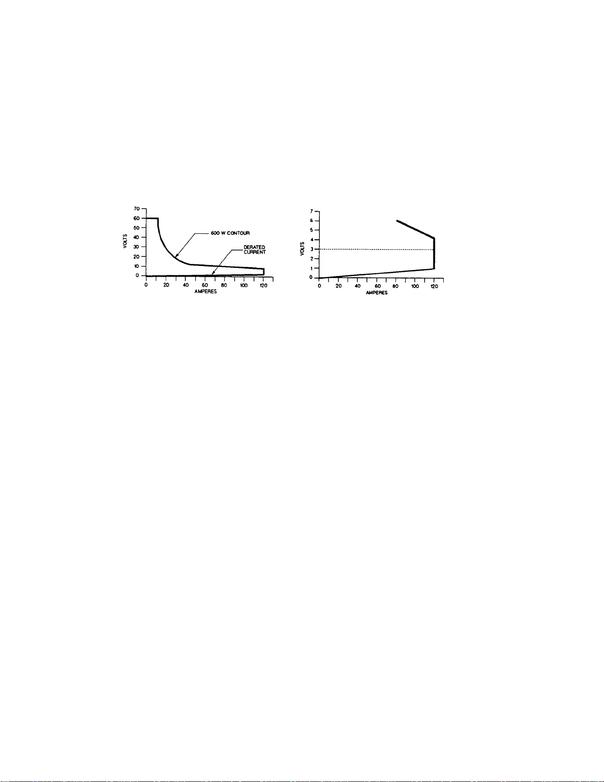
Table 60504-1. Specification and Supplemental Characteristics
SPECIFICATIONS
DC Input Rating:
Current: 0 to 120 A
Voltage: 3 V to 60 V (minimum dc operation from 0 to 2 V for 0 to 10 A)
Power: 600 W at 40 °C (derated to 450 W at 55 °C)
A. OPERATING CHARACTERISTICS B. DERATED CURRENT DETAIL
Constant Current Mode:
Ranges: 0 to 12 A; and 0 to 120 A
Accuracy: (after 30 second wait): ± 0.12% ± 130 mA (both ranges)
Resolution: 3.2 mA (12 A range); 32 mA (120 A range)
Regulation: 10 mA (both ranges)
Temperature Coefficient: 120 ppm/°C ± 8 mA/°C (both ranges)
Constant Resistance Mode:
Ranges: 0.017 to 0.5 Ω; 0.5 Ω to 500 Ω; and 5 Ω to 5 k
Accuracy: ± 0.8% ± 5 mΩ with ≥ 12 A at input (0.5 Ω range);
Resolution: 0.14 mΩ (0.5 Ω range); 0.54 mS (500 kΩ range); 0.054 mS (50 kΩ range)
Regulation: 20 mV with remote sensing (0.5 Ω range); 10 mA (500 Ω and 5 kΩ ranges)
Temperature Coefficient: 800 ppm/°C ± 0.2 mΩ/°C (0.5 Ω range);
Constant Voltage Mode:
Range: 0 to 60 V
Accuracy: ± 0.1% ± 50 mV
Resolution: 16 mV
Regulation: 20 mV (remote sense); 100 mV (local sense)
Temperature Coefficient: 100 ppm/°C ± 5 mV/°C
Ω
± 0.3% ± 18 mS with ≥ 6 V at input (500 Ω and 5 kΩ ranges)
300ppm/°C ± 1.2 mS/°C (500 Ω and 5 kΩ ranges)
2
Page 5

Table 60504-1 Specifications and Supplemental Characteristics (continued)
Transient Operation:
Continuous Mode
Frequency Range: 0.25 Hz to 10 kHz
Frequency Resolution: 4%
Frequency Accuracy: 3%
Duty Cycle Range: 3% to 97% (0.25 Hz to 1 kHz); 6% to 94% (1 kHz to 10 kHz)
Duty Cycle Resolution: 4%
Duty Cycle Accuracy: 6% of setting ± 2%
Pulsed Mode
Pulse Width: 50
Transient Current Level (0 to 12 A and 0 to 120 A ranges):
Resolution: 52 mA (12 A range); 520 mA (120 A range)
Accuracy: ± 0.15% ± 160 mA (12 A range); ± 0.15% ± 700 mA (120 A range)
Temperature Coefficient: 150 ppm/°C ± 10 mA/°C
Transient Resistance Level (0.017 to 0.5 Ω, 0.5 Ω to 500 Ω, and 5 Ω to 5 kΩ ranges):
Resolution: 2.2 mΩ (0.5 Ω range); 8.7 mS (500 Ω range); 0.87 mS (5 kΩ range)
Accuracy: ± 0.8% + 7 mΩ with > 12 A at input (0.5 Ω range)
µ
s ± 3% minimum; 4 s ± 3% maximum
± 0. 3% + 26 mS with ≥ 6 V at input (500 Ω range)
± 0.3% + 18 mS with ≥ 6 V at input (5 kΩ range)
Transient Voltage Level (0 to 60 V):
Resolution: 260 V
Accuracy: ± 0.15% ± 300 V
Temperature Coefficient: 150 ppm/°C ± 5 mV/°C
Current Readback:
Resolution: 34 mA (via GPIB); 100 mA (front panel)
Accuracy: (after 30 minute wait): ± 0.1% ± 110 mA
Temperature Coefficient: 100 ppm/
Voltage Readback:
Resolution: 17 mV (via GPIB); 20 mV (front panel)
Accuracy: ± 0.1% ± 45 mV
Temperature Coefficient: 100 ppm/°C ± 2 mV/°C
Maximum Readback Capability: 65 to 70 V (typical)
Power Readback:
Accuracy: ± 0.2% ± 8 W
°
C ± l mA/ °C
3
Page 6

Table 60504-1 Specifications and Supplemental Characteristics (continued)
External Analog Programming 0 to 10 V (dc or ac):
Bandwidth: 10 kHz (3 db frequency)
Accuracy: ± 4% ± 200 mA (0 to 12 A range)
± 4% ± 400 mA (0 to 120 A range)
± 0.8% ± 200 mV (0 to 60 V range)
Temperature Coefficient: 100 ppm/°C ± 12 mA/°C (current ranges)
100 ppm/°C ± 1 mV/°C (voltage range)
External Current Monitor (0 to 10 V):
Accuracy: ± 0.4% ± 170 mA (referenced to analog common)
Temperature Coefficient: 100 ppm/°C ± l0 mA/°C
External Voltage Monitor (0 to 10 V):
Accuracy: ± 0.4% ± 60 mV (referenced to analog common)
Temperature Coefficient: 100 ppm/
Remote Sensing: 5 Vdc maximum between sense and input binding posts
°
C ± 2 mV/ °C
Maximum Input Levels:
Current: 122.4 A (programmable to lower limits)
Voltage: 75 V
Minimum Operating Voltage: 2 V (derated to 0 V at 0 A)
PARD (20 Hz to 10 MHz noise):
Current: 6 mA rms/60 mA p-p
Voltage: 8 mV rms
DC Isolation Voltage: ± 240 Vdc between + or - input binding post and chassis ground
Digital Inputs:
Vlo: 0.9 V maximum at Ilo = -1 mA
Vhi 3.15 V minimum (pull-up resistor on input)
Digital Outputs:
Vlo: 0.72 V maximum at Ilo = 1 mA
Vhi: 4.4 V minimum at Ilo - 20 µA
SUPPLEMENTAL CHARACTERISTICS
Programmable Slew Rate (For any given input transition, the time required will be either the total slew time or a minimum
transition time, whichever is longer. The minimum transition time increases when operating with input currents under 2 A.
The following are typical values; ± 25% tolerance):
4
Page 7

Table 60504-1 Specifications and Supplemental Characteristics (continued)
Current Slew Rate:*
Rate # 120 A Range Step 12 A Range Step Transition Time
1 2 A/ms 0.2 A/s 8.0 ms
2 5 A/ms 0.5 A/s 3.2 ms
3 10 A/ms 1 A/ms 1.6 ms
4 20 A/ms 2 A/ms
5 50 A/ms 5 A/ms
6 100 A/ms 10 A/ms
7
8
9
10
11
12
Voltage Slew Rate:
Rate # Voltage Range Step Transition Time*
1 1 V/ms 8.0 ms
2 2.5 V/ms 3.2 ms
3 5 V/ms 1.6 ms
4 10 V/ms
5 25 V/ms
6 50 V/ms
7
8
9
0.2 A/µs
0.5 A/µs
1 A/µs
2 A/µs 0.2 A/µs 12 µs
5 A/µs 0.5 A/µs 12 µs
10 A/µs 1 A/µs 12 µs
*AC performance specified from 3 to 60 V.
0.1 V/µs 85 µs
0.25 V/µs 85 µS
0.5 V/µs 85 µS
*Transition time based on low capacitance current source.
20 A/ms
50 A/ms
100 A/ms
800 µs
320 µs
160 µs
800 µs
320 µs
160 µs
80 µs
32 µs
16 µs
Resistance Slew Rate (0.5 Ω range): Uses the value programmed for voltage slew rate.
Resistance Slew Rate (500 Ω and 5 kΩ ranges): Uses the value programmed for current slew rate.
Transient Current Overshoot (When programmed from 0A):
Range Transient Current Level Current Slew Rate Overshoot*
120 A 24-120 A All slew rates 0
6 A
6 A
6 A
6 A
12 A
12 A
0.5 A/µs and 10 A/µs
2 A/µs
1 A/µs
0.2 A/ms to 0.5 A/µs
2 A/ms to 2 A/µs
5 A/ms and 10 A/µs
5
6%
3%
1%
0
0
2%
Page 8
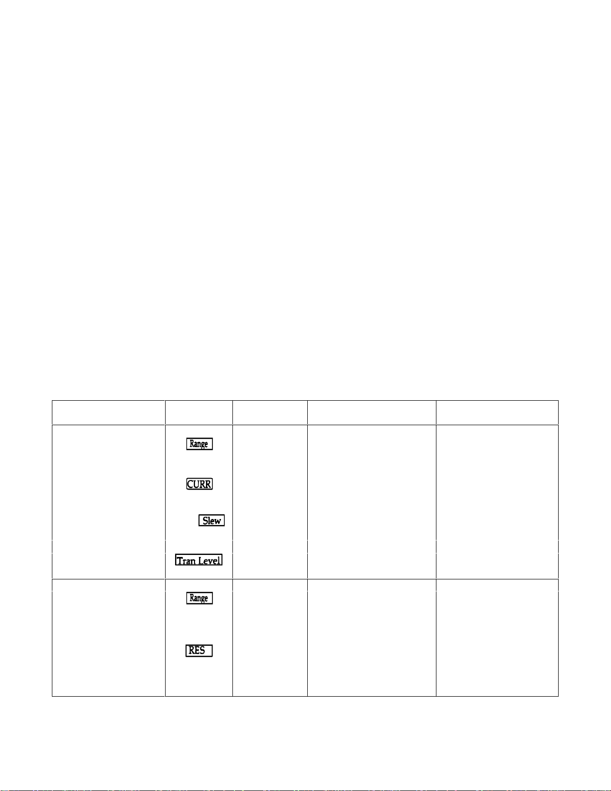
Range Transient Current Level Current Slew Rate Overshoot*
12 A 6 A
6 A
12 A
12 A
*Overshoot may be higher during the first five seconds of programming if unit has been operating at full
current. Overshoot values assume a total inductance of lµH, or less, in the load leads connected to the
D.U.T.
Source Turn-On Current Overshoot: Less than 10% of final value (in CC and CR modes when connected to power
supplies with voltage rise times of greater than 500µs).
Programmable Short Circuit: 0.17 Ω (0.012 Ω typical)
Programmable Open Circuit: 20 kΩ (typical)
Drift Stability (over an 8 hour interval):
Current: ±0.03% ± 20 mA
Voltage: ±0.01% ± 10 mV
Reverse Current Capacity: 120 A when unit is on; 60 A when unit is off
Weight: 5.4 kg (12 lbs.)
0.5 A/µs, 1 A/µs
0.2 A/µs to 0.2 A/µs
1 A/µs
0.2 A/ms to 0.5 A/µs
5%
0
2%
0
Table 60504-2. Programming Ranges
Function Front Panel Front Panel HPSL Command Range of Values
Key Display (Short Form)
Constant Current
Set Range C:RNG value "CURR:RANG value"
Low Range
High Range
Set Main Level CURR value "CURR value"
Low Range 0 to 12 A
High Range 0 to 120 A
Set Slew Rate
Low Range
High Range
Set Transient Level C:TLV value "CURR:TLEV value" same as main level
*Set Triggered Level "CURR:TRIG value" same as main level
Constant Resistance
Set Range R:RNG value "RES:RANG value"
Low Range
Middle Range
High Range
Set Main Level RES value "RES value"
Low Range
Middle Range
High Range
(shift)
C:SLW value "CURR:SLEW value"
≥
0 and ≤ 12 A
> l2 A and ≤ 120 A
0.0002 to 1 (A/µs)
0.002 to 10 (A/µs)
≥ 0 and ≤ 0.5 Ω
> 0.5 Ω and ≤ 500 kΩ
>500 Ω and ≤ 5 kΩ
0 to 0.5 Ω
0.5 Ω to 500 Ω
5 Ω to 5 kΩ
6
Page 9
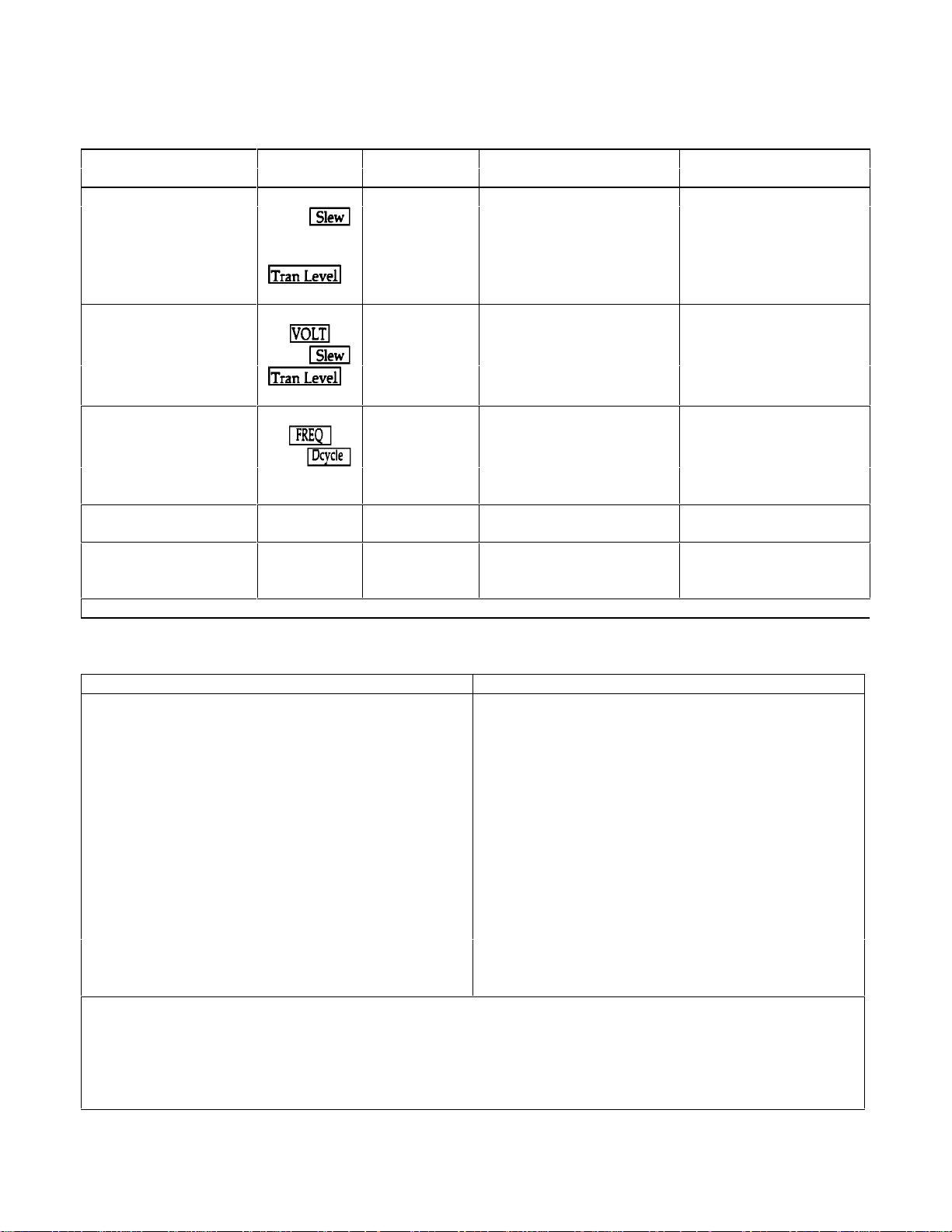
Table 60504-2. Programming Ranges (continued)
Function Front Panel Front Panel HPSL Command Range of Values
Key Display (Short Form)
Constant Resistance
Set Slew Rate
Low Range V:SLW value "VOLT:SLEW value" same as voltage slew
Middle/High Range C:SLW value "CURR:SLEW value" same as current slew
Set Transient Level R:TLV value "RES:TLEV value" same as main level
*Set Triggered Level "RES:TRIG value" same as main level
Constant Voltage
Set Main Level VOLT value "VOLT value" 0 to 60 V
Set Slew Rate
Set Transient Level V:TLV value "VOLT:TLEV value" same as main level
*Set Triggered Level "VOLT:TRIG value" same as main level
Transient Operation
Set Frequency FREQ value "TRAN:FREQ value" 0.25 Hz to 10 kHz
Set Duty Cycle
*Set Pulse Width "TRAN:TWID value" 0.00005 to 4 s
Trigger Operation
*Set Trigger Period "TRIG:TIM value" 0.000008 to 4 s
Current Protection
*Set Current Level "CURR:PROT value" 0 to 122.4 A
*Set Delay Time "CURR:PROT:DEL value" 0 to 60 s
(shift)
(shift)
(shift)
V:SLW value "VOLT:SLEW value"
DCYCLE value "TRAN:DCYC value" 3-97% (0.25 Hz-1 kHz)
*Can only be programmed remotely via the GPIB.
0.001 to 0.5 (V/µs)
6-94% (1 kHz-10 kHz)
Table 60504-3. Factory Default Settings
Function Settings Function Setting
CURR level 0 A Mode (CC, CR, CV) CC
CURR transient level 0 A Input (on/off) on
*CURR slew rate
CURR range 120 A
*CURR protection (on/off) off ***TRAN mode continuous
**CURR protection level 122.4 A (continuous, pulse, toggle)
**CURR protection delay 15 s TRAN frequency 1 kHz
RES level
RES transient level
RES range
VOLT level 60 V **TRIG period 0.001 s
VOLT transient level 60 V **PORT0 output (on/off) off (logic 0)
VOLT slew rate
The *RST command resets the CURR slew rate to 0.83 A/µ, not to the factory default.
**Can only be programmed remotely via the GPIB.
***Continuous transient mode is the only mode available at the front panel. Pulsed, toggled, and continuous modes can
all be programmed remotely via the GPIB.
2 A/µs
Ω
500
Ω
500
500 Ω
5 V/µs
Short (on/off) off
Transient operation (on/off) off
TRAN duty cycle 50%
**TRAN pulse width 0.5 ms
**TRIG source hold
(bus, external, hold, timer, line)
**CAL mode (on/off) off
7
Page 10
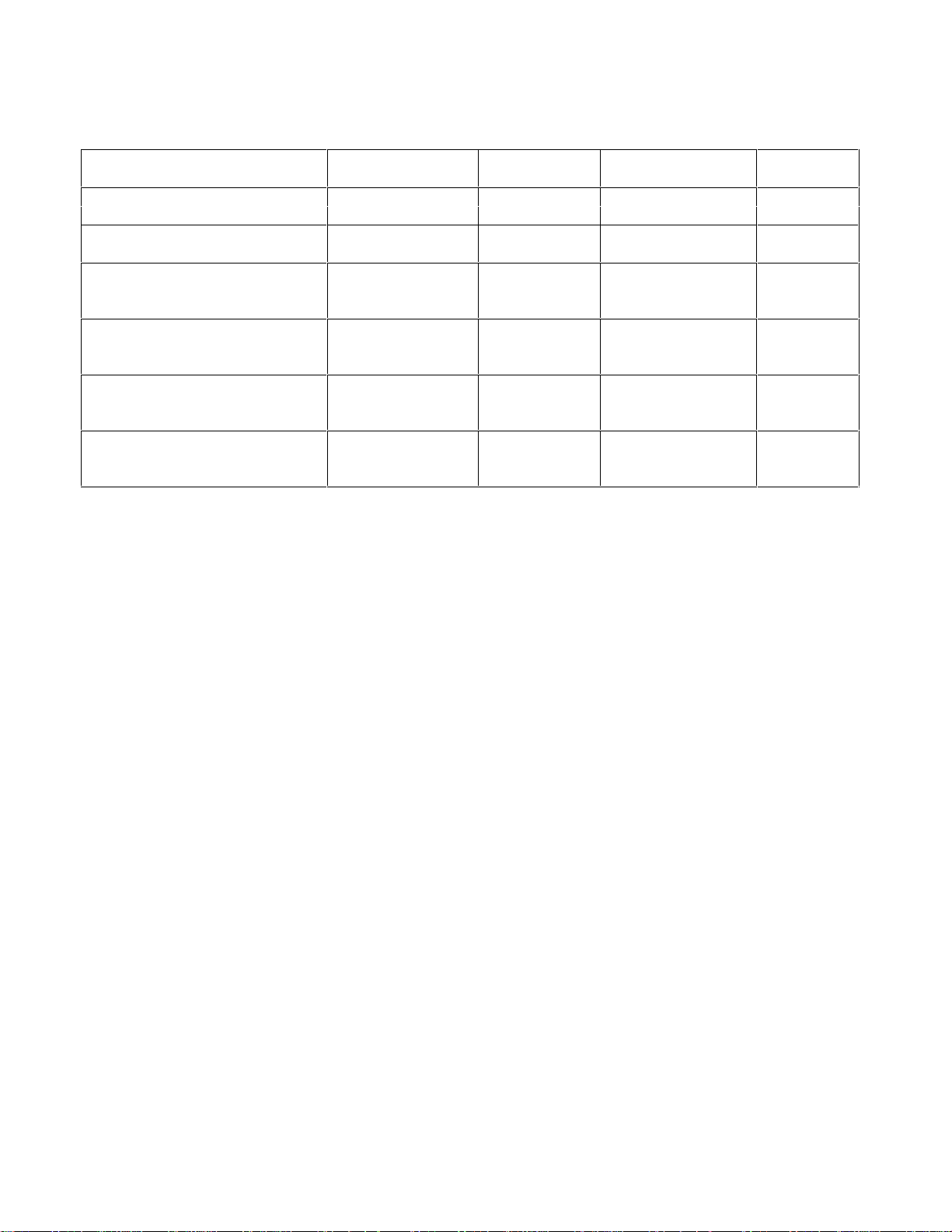
Table 60504-4. Calibration Information
Ranges and
Calibration Points
High Current Range Hi_curr_rng 120 5 V/121 A 300 A
High Current Offset Hi_curr_offset 0.0594
Low Current Range Lo_curr_rng 12 5 V/15 A 300 A
Low Current Offset Lo_curr_offset 0.0497
Voltage Range N/A N/A 61 V/10 A N/A
Voltage Hi point Volt_hipt 60
Voltage Lo point Volt_lopt 2.7
Low Resistance Range Lo_res_rng 0.5 15 V/21.8 A 100 A
Low Resistance Hi point Lo_res_hipt 0.499
Low Resistance Lo point Lo_res_lopt 0.02
Middle Resistance Range Mid_res_rng 5 10.9 V/30 A 100 A
Middle Resistance Hi point Mid_res_hipt 15
Middle Resistance Lo point Mid_res_lopt 0.5
High Resistance Range Hi_res_rng 501 60 V/12 A 100 A
High Resistance Hi point Hi_res_hipt 50
High Resistance Lo point Hi_res_lopt 6
Variables Variables
Value
Power Supply
Settings
Current
Shunt
8
Page 11

Agilent Sales and Support Office
For more information about Agilent Technologies test and measurement products, applications, services, and for a current
sales office listing, visit our web site: http://www.agilent.com/find/tmdir
You can also contact one of the following centers and ask for a test and measurement sales representative.
United States:
Agilent Technologies
Test and Measurement Call Center
P.O. Box 4026
Englewood, CO 80155-4026
(tel) 1 800 452 4844
Canada:
Agilent Technologies Canada Inc.
5150 Spectrum Way
Mississauga, Ontario
L4W 5G1
(tel) 1 877 894 4414
Europe:
Agilent Technologies
Test & Measurement European Marketing Organisation
P.O. Box 999
1180 AZ Amstelveen
The Netherlands
(tel) (31 20) 547 9999
Latin America:
Agilent Technologies
Latin American Region Headquarters
5200 Blue Lagoon Drive, Suite #950
Miami, Florida 33126
U.S.A.
(tel) (305) 267 4245
(fax) (305) 267 4286
Australia/New Zealand:
Agilent Technologies Australia Pty Ltd
347 Burwood Highway
Forest Hill, Victoria 3131
(tel) 1-800 629 485 (Australia)
(fax) (61 3) 9272 0749
(tel) 0 800 738 378 (New Zealand)
(fax) (64 4) 802 6881
Asia Pacific:
Agilent Technologies
24/F, Cityplaza One, 1111 King’s Road,
Taikoo Shing, Hong Kong
tel: (852)-3197-7777
fax: (852)-2506-9284
Japan:
Agilent Technologies Japan Ltd.
Measurement Assistance Center
9-1, Takakura-Cho, Hachioji-Shi,
Tokyo 192-8510, Japan
(tel) (81) 426 56 7832
(fax) (81) 426 56 7840
Technical data is subject to change.
9
 Loading...