

Page 1

Agilent 54753A and 54754A
TDR Plug-in Modules
Programmer’s Guide
Page 2
Notices
© Agilent Technologies, Inc. 2000-2004
No part of this manual may be reproduced in any form or by any means
(including electronic storage and
retrieval or translation into a foreign language) without prior agreement and written consent from Agilent Technologies,
Inc. as governed by United States and
international copyright lays.
Manual Part Number
54754-90014
Edition
July 2004
Printed in Malaysia
Agilent Technologies, Inc.
Digital Signal Analysis Division
1400 Fountaingrove Parkway
Santa Rosa, CA 95403, USA
Warranty
The material contained in this document
is provided “as is,” and is subject to being
changed, without notice, in future editions. Further, to the maximum extent
permitted by applicable law, Agilent disclaims all warranties, either express or
implied, with regard to this manual and
any information contained herein, including but not limited to the implied warranties of merchantability and fitness for a
particular purpose. Agilent shall not be
liable for errors or for incidental or consequential damages in connection with the
furnishing, use, or performance of this
document or of any information contained herein. Should Agilent and the
user have a separate written agreement
with warranty terms covering the material in this document that conflict with
these terms, the warranty terms in the
separate agreement shall control.
Restricted Rights Legend
If software is for use in the performance
of a U.S. Government prime contract or
subcontract, Software is delivered and
licensed as “Commercial computer software” as defined in DFAR 252.227-7014
(June 1995), or as a “commercial item” as
defined in FAR 2.101(a) or as “Restricted
computer software” as defined in FAR
52.227-19 (June 1987) or any equivalent
agency regulation or contract clause. Use,
duplication or disclosure of Software is
subject to Agilent Technologies’ standard
commercial license terms, and non-DOD
Departments and Agencies of the U.S.
Government will receive no greater than
Restricted Rights as defined in FAR
52.227-19(c)(1-2) (June 1987). U.S. Government users will receive no greater
than Limited Rights as defined in FAR
52.227-14 (June 1987) or DFAR 252.2277015 (b)(2) (November 1995), as applicable in any technical data.
Safety Notices
CAUTION
Caution denotes a hazard. It calls attention
to a procedure which, if not correctly performed or adhered to, could result in
damage to or destruction of the product.
Do not proceed beyond a caution sign
until the indicated conditions are fully
understood and met.
WARNING
Warning denotes a hazard. It calls attention
to a procedure which, if not correctly performed or adhered to, could result in
injury or loss of life. Do not proceed
beyond a warning sign until the indicated
conditions are fully understood and met.
TTechnology Licenses
MS-DOS is a U.S. registered trademark
of Microsoft Corporation.
ii
Page 3

Introduction
Introduction
54750A/83480A
Mainframes
86100-Series
Mainframes
Notational
Conventions
For controlling 54753A and 54754A TDR plug-in modules that are installed in
a 54750A or 83480A mainframes, refer to the following books:
• This manual, the 54753A and 54754A TDR Plug-in Modules Programmer’s
Guide.
• 54753A and 54754A Programmer’s Quick Reference.
• 54750A Oscilloscope and 83480A Analyzer Programmer’s Guide for information about programming the oscilloscope.
• 54753A and 54754A User’s Guide for general information about the operation of the TDR plug-in module.
For 54753A and 54754A TDR plug-in modules that are installed in an 86100series mainframe, refer to the following books:
• 86100-series programmer’s guide.
• 86100-series online help.
computer type. All characters appearing in computer type are key
words and must be entered exactly as shown.
CAPITAL LETTERS. Capital letters indicate the short form of a command.
The actual command is not case sensitive and can be entered in upper or
lower case.
<> Angular brackets enclose words or characters that symbolize a program
code parameter or an GPIB command.
::= "is defined as." For example, <A> ::= <B> indicates that <A> can be
replaced by <B> in any statement containing <A>.
| "or." Indicates a choice of one element from a list. For example, <A> | <B>
indicates <A> or <B> but not both.
... An ellipsis (trailing dots) indicate that the preceding element may be
repeated one or more times.
iii
Page 4

Introduction
[ ] Square brackets indicate that the enclosed items are optional.
{ } When several items are enclosed by braces, one, and only one of these
elements may be selected.
Definitions d ::= A single ASCII numeric character, 0-9.
n ::= A single ASCII non-zero, numeric character, 1-9.
<NL> ::= Newline or Linefeed (ASCII decimal 10).
<sp> ::= space character.
<white_space> ::= space(s) and tabs.
iv
Page 5

Contents
1 Introduction
2 Root Level Commands
BLANk 2–7
COMMents 2–8
DIGitize 2–8
MENU 2–10
STORe:WAVEform 2–11
VIEW 2–12
3 Acquire Commands
BEST 3–3
4 Calibrate Commands
SAMPlers 4–4
5 Channel Commands
OFFSet 5–4
RANGe 5–5
SCALe 5–6
TDRSkew 5–8
UNITs 5–9
6 Disk Commands
LOAD 6–4
STORe 6–5
7 Display Commands
ASSign 7–6
Contents–1
Page 6

Contents
8 Function Commands
ADD 8–6
BWLimit 8–6
DIFFerentiate 8–7
DIVide 8–8
FFTMagnitude 8–8
INTegrate 8–9
INVert 8–10
MAGNify 8–10
MAXimum 8–11
MINimum 8–12
MULTiply 8–12
SUBTract 8–13
VERSus 8–14
9 Histogram Commands
Histogram Commands 9–2
WINDow:SOURce 9–5
10 Limit Test Commands
SWAVeform 10–8
11 Marker Commands
MODE 11–6
PROPagation 11–6
REFerence 11–8
X1Y1source 11–9
X2Y2source 11–10
XUNITs 11–11
YUNITs 11–12
Contents–2
Page 7

12 Mask Test Commands
AMASk:SOURce 12–10
SWAVeform 12–11
SCALe:SOURce 12–12
13 Measure Commands
DELTatime 13–11
DUTycycle 13–12
FALLtime 13–13
FREQuency 13–15
NWIDth 13–16
OVERshoot 13–18
PERiod 13–19
PREShoot 13–20
PWIDth 13–22
RISetime 13–23
SOURce 13–24
TEDge 13–26
TMAX 13–27
TMIN 13–29
TVOLt 13–30
VAMPlitude 13–31
VAVerage 13–32
VBASe 13–34
VLOWer 13–35
VMAX 13–36
VMIDdle 13–37
VMIN 13–38
VPP 13–40
VRMS 13–41
VTIMe 13–43
VTOP 13–44
VUPper 13–45
Contents
Contents–3
Page 8

Contents
14 TDR Commands
RESPonse:CALibrate 14–5
RESPonse:CALibrate:CANCel 14–5
RESPonse:CALibrate:CONTinue 14–5
PRESet 14–6
RATE 14–7
RESPonse 14–8
RESPonse:HORizontal 14–9
RESPonse:HORizontal:POSition 14–10
RESPonse:HORizontal:RANGe 14–11
RESPonse:RISetime 14–12
RESPonse:TDRDest 14–14
RESPonse:TDRTDT 14–15
RESPonse:TDTDest 14–16
RESPonse:VERTical 14–18
RESPonse:VERTical:OFFSet 14–19
RESPonse:VERTical:RANGe 14–20
STIMulus 14–21
15 Waveform Commands
SOURce 15–5
16 Waveform Memory Commands
SAVe 16–4
Contents–4
Page 9
1
Introduction
Page 10

Introduction
The 54753A and 54754A Programmer’s Guide contains
descriptions of the remote programming commands that apply to the
TDR plug-in modules.
1–2
Page 11
2
Root Level Commands
Page 12

Root Level Commands
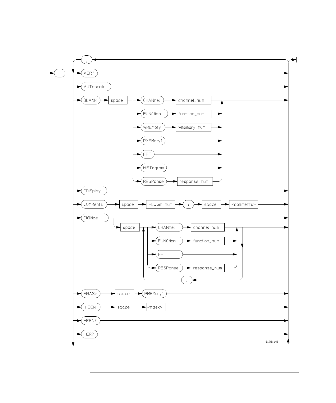
Root level commands control many of the basic operations of the
oscilloscope; most of these can also be selected by pressing the
labeled keys on the front panel. These commands are always
recognized by the command parser if they are prefixed with a colon,
regardless of the current tree position. After executing a root level
command, the parser is positioned at the root of the command tree.
The TDR plug-in modifies the operation of the following root level
commands:
BLANk
•
COMMents
•
DIGitize
•
MENU
•
STORe:WAVeform
•
VIEW
•
2–2
Page 13
Root Level Commands
Root Level Command Syntax Diagram
2–3
Page 14
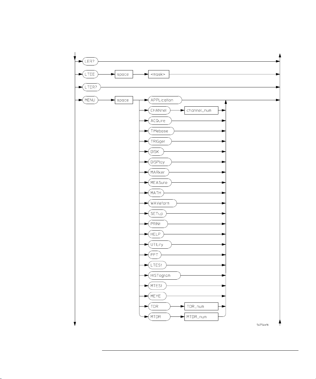
Root Level Commands
Root Level Command Syntax Diagram (continued)
2–4
Page 15
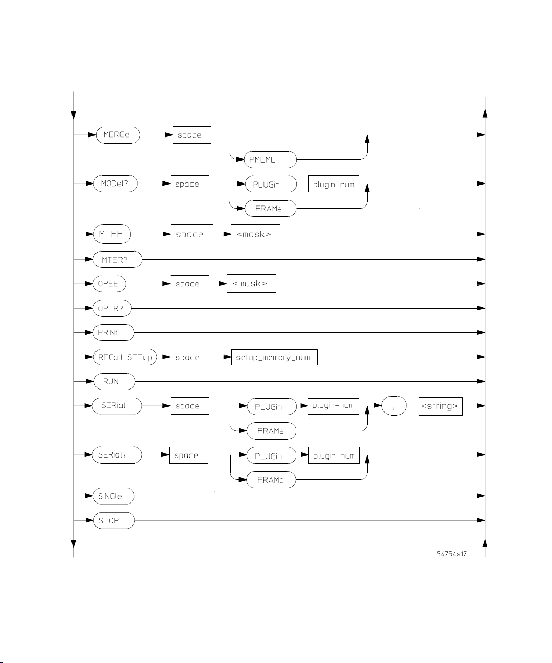
Root Level Commands
Root Level Command Syntax Diagram (continued)
2–5
Page 16
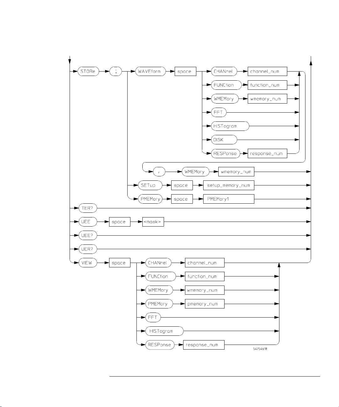
Root Level Commands
Root Level Command Syntax Diagram (continued)
2–6
Page 17

BLANk
Root Level Commands
BLANk
Command
Example
<number>
:BLANk {CHANnel<number> | WMEMory<number> |
FUNCtion <number> | FFT | RESPonse<number> |
HISTogram | PMEMory1}
Turns off an active channel, function, waveform memory, pixel memory, FFT,
histogram, or TDR response. The VIEW command turns them on.
For channels: an integer, 1 through 4, indicating the slot in which the channel
resides, followed by an optional A or B identifying which of two possible
channels in the slot is being referenced. For functions: 1 or 2. For waveform
memories (WMEMory): 1, 2, 3, or 4. For pixel memories (PMEMory): 1. For
TDR response: 1, 2, 3, or 4.
The following example turns off TDR response 1.
10 OUTPUT 707;":BLANK:RESPONSE1"
20 END
2–7
Page 18

Root Level Commands
COMMents
COMMents
Command
<comments>
Example
Query
Command
<number>
:COMMents {PLUGin<number>, <comments>}
Sets the comments field for the plugin. This field is used to describe options
included in the plugin, or for user commands about the plugin.
Represents the plugin slot numbered 1 through 4.
Represents the unquoted string.
The following example turns off TDR response 1.
10 OUTPUT 707;":COMMENTS PLUGIN1"
20 END
:COMMents? PLUGin<number>
Returns the comments field associated with the plugin.
DIGitize
:DIGitize [<waveform_name>][,<waveform_name>]
Invokes a special mode of data acquisition that is more efficient than using
the RUN command. This command initializes the selected channels,
functions, responses, or FFT to “unacquired,” then acquires them according
to the current instrument settings. When all signals are completely acquired,
the instrument is stopped.
If channel, function, response, or FFT parameters are specified, then these
are the only waveforms acquired. To speed acquisition, these waveforms are
not displayed and their display state is “off.” Subsequent to the digitizing
operation, the waveform display may be turned on, if desired. Other sources
are turned off and their data are invalidated.
2–8
Page 19

Root Level Commands
You use the ACQuire subsystem to set up conditions, such as TYPe and
COUNt, for the next DIGitize command. Use the WAVeform subsystem
commands to specify how data is transferred from the instrument to the
controller and how to interpret the data.
N O T E
Even though digitized waveforms are not displayed, the full range of
measurement and math operators may be used on them.
If the DIGitize command is issued without parameters, the digitize operation is
performed on the channels, functions, responses, and FFT that were acquired
with a previous digitize, run, or single operation. In this case, the display state of
the acquired waveforms is not changed. Because the command executes more
quickly without parameters, this form of the command is useful for repetitive
measurement sequences. Also, this mode can be used if it is desirable to view
the digitized results because the display state of the digitized waveforms is not
affected.
DIGitize
<waveform_name>
<number>
Example
The data acquired with the DIGitize command are placed in the normal channel,
function, response, or FFT memories just as when acquired via the RUN
command.
{CHANnel<number> | FUNCtion<number> | FFT |
RESPonse<number>}
For channels: an integer, 1 through 4, indicating the slot in which the channel
resides, followed by an optional A or B identifying which of two possible
channels in the slot is being referenced. For functions: 1 or 2. For responses:
1, 2, 3, or 4.
The following example uses the DIGitize command to acquire data on
response 1 and function 2.
10 OUTPUT 707;":DIGITIZE RESPONSE1,FUNCTION2"
20 END
2–9
Page 20

Root Level Commands
MENU
MENU
Command
Example
<number>
:MENU {APPLication | CHANnel<number> | ACQuire |
TIMebase | TRIGger | DISK | DISPlay | MARker |
MEASure | MATH | WAVeform | SETup | PRINt |
HELP | UTILity | FFT | LTESt | HISTogram |
MTESt | MEYE | TDR<number> | MTDR<number>}
For channels, indicates the slot (1 through 4) in which the channel resides,
followed by an optional A or B identifying which of two possible channels in
the slot is being referenced.
For TDR, controls the TDR/TDT menus for channels 2 and 4.
For MTDR, controls the TDR/TDT menus for channels 2 and 4.
The following example allows you to control the TDR menu for channel 2.
10 OUTPUT 707;":MENU TDR2"
20 END
2–10
Page 21

STORe:WAVEform
Root Level Commands
STORe:WAVEform
Command
Example
<number>
:STORe:WAVEform {CHANnel<number> |
FUNCtion<number> | WMEMory<number> | HISTogram |
FFT | RESPonse<number>},{WMEMory<number>}
Copies a channel, function, stored waveform, histogram, TDR response, or
FFT to a waveform memory. The first parameters specifies the source of the
copy and can be any channel, function, waveform memory, histogram, TDR
response, or the FFT. The second parameter is the destination of the copy,
and can be any waveform memory.
For channels: an integer, 1 through 4, indicating the slot in which the channel
resides, followed by an optional A or B identifying which of two possible
channels in the slot is being referenced. For functions: 1 or 2. For waveform
memories (WMEMory): 1, 2, 3 or 4. For responses: 1, 2, 3, or 4.
The following example copies response 1 to waveform memory 3.
10 OUTPUT 707;":STORE:WAVEFORM RESPONSE1,WMEMORY3"
20 END
2–11
Page 22

Root Level Commands
VIEW
VIEW
Command
Example
<number>
:VIEW {CHANnel<number> | WMEMory<number> |
FUNCtion <number> | FFT | RESPonse<number> |
HISTogram | PMEMory1}
Turns on a channel, function, pixel memory, waveform memory, TDR
response, histogram, or FFT. Use the BLANk command to turn these off.
For channels: an integer, 1 through 4, indicating the slot in which the channel
resides, followed by an optional A or B identifying which of two possible
channels in the slot is being referenced. For functions: 1 or 2. For waveform
memories (WMEMory): 1, 2, 3, or 4. For TDR responses: 1, 2, 3, or 4. For
pixel memories (PMEMory): 1.
The following example turns on TDR response 1.
10 OUTPUT 707;":VIEW RESPONSE1"
20 END
2–12
Page 23
3
Acquire Commands
Page 24
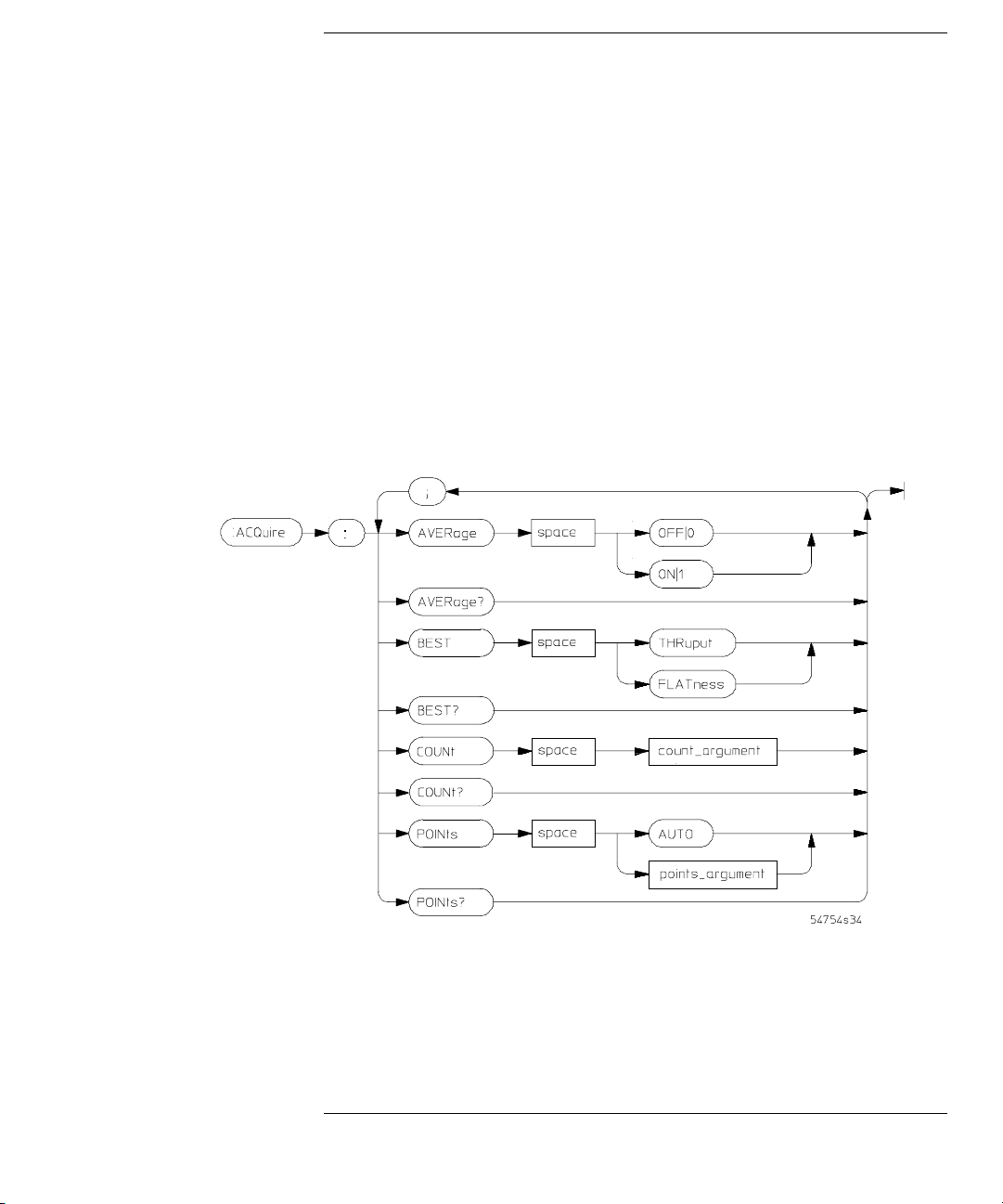
Acquire Commands
The ACQuire subsystem commands set up conditions for executing a
DIGitize root level command to acquire waveform data. The
commands in this subsystem select the type of data, the number of
averages, and the number of data points.
The TDR plug-in adds the following ACQuire subsystem command:
BEST
•
Acquire Subsystem Commands Syntax Diagram
3–2
Page 25

BEST
Acquire Commands
BEST
Command
Example
Query
Returned Format
Example
:ACQuire:BEST {THRuput | FLATness}
When averaging is enabled with ACQuire:AVERage, the FLATness option
improves the step flatness by using a signal processing algorithm within the
instrument. You should use this option when performing TDR measurements
or when step flatness is important. The THRuput option improves the
instrument’s throughput and should be used whenever best flatness is not
required.
The following example sets the instrument to best step flatness:
10 OUTPUT 707;":ACQUIRE:BEST FLATNESS"
20 END
:ACQuire:BEST?
The :ACQuire:BEST? query returns the current acquisition algorithm setting.
[:ACQuire:BEST]{THRuput | FLATness}<NL>
The following example obtains the current setting of the acquisition
algorithm from the instrument, stores it in the variable Best, then prints the
contents of the variable to the controller’s screen:
10 DIM Best$[50] !Define variable
20 OUTPUT 707;":ACQUIRE:BEST?"
30 ENTER 707;Best$
40 PRINT Best$
50 END
3–3
Page 26

3–4
Page 27
4
Calibrate Commands
Page 28
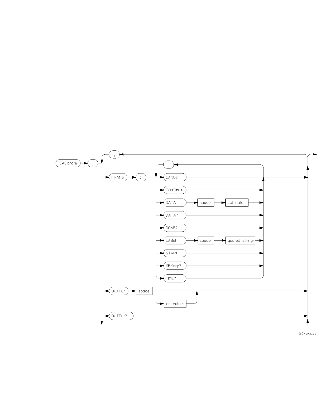
Calibrate Commands
The commands in the Calibration subsystem initiate instrument
calibration over the GPIB. Firmware revision A.02.00 adds the
following calibration command to the calibration subsystem:
SAMPlers
•
Calibration Subsystem Syntax Diagram
4–2
Page 29
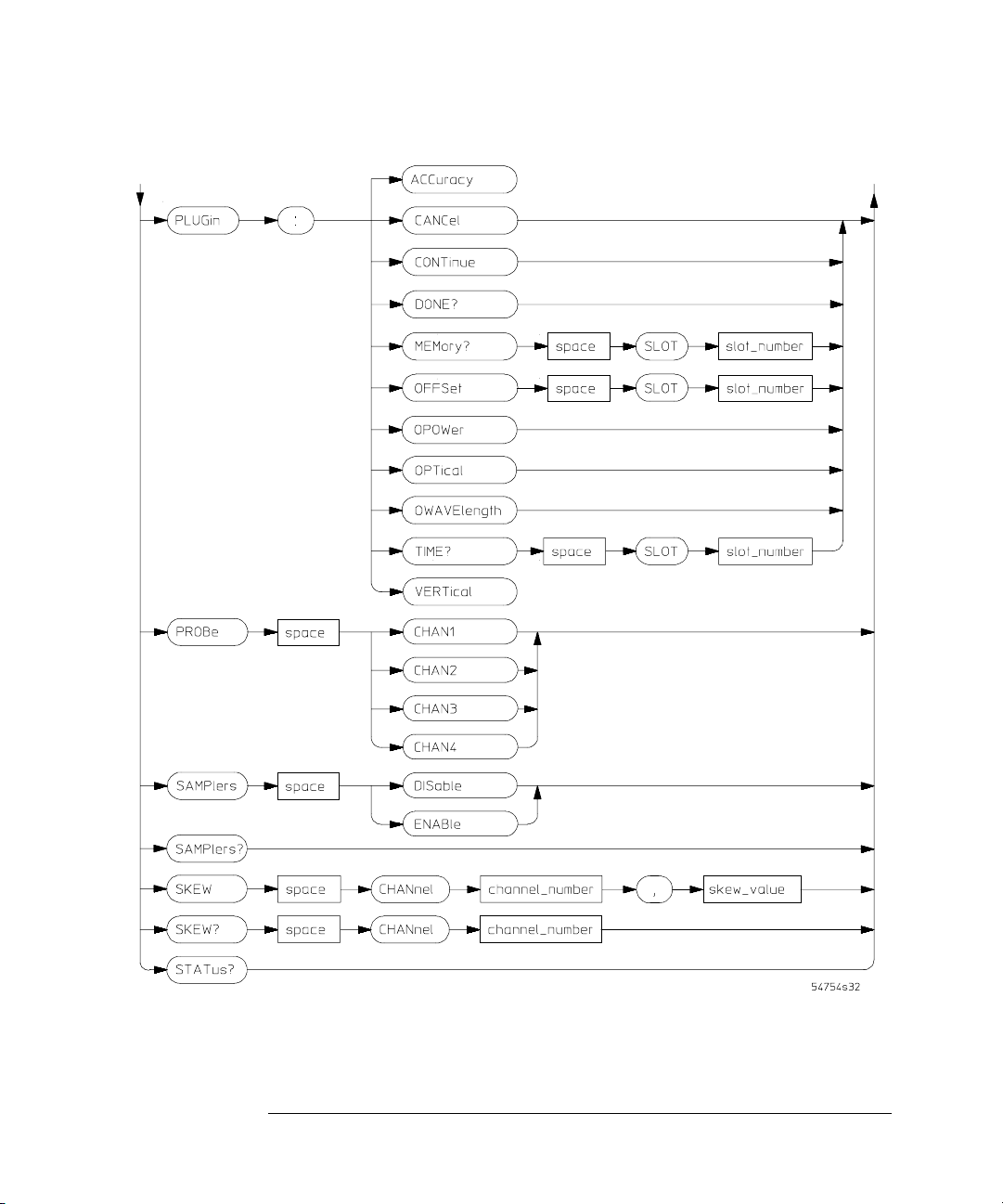
Calibrate Commands
Calibration Subsystem Syntax Diagram (continued)
4–3
Page 30

Calibrate Commands
SAMPlers
SAMPlers
Command
Example
Query
Returned Format
Example
:CALibrate:SAMPlers {DISable | ENABle}
Enables or disables the samplers in the plug-in.
The following example enables sampler calibration for the TDR plug-in.
10 OUTPUT 707;":CALIBRATE:SAMPLERS ENABLE"
20 END
:CALibrate:SAMPlers?
Returns the current calibration enable/disable setting.
[:CALibrate:SAMPlers]{DISable | ENABle}<NL>
The following example gets the current setting for sampler calibration, stores
it in the variable Sampler, and prints the contents of the variable to the
screen.
10 DIM Sampler$[50] !Define variable
20 OUTPUT 707;":CALIBRATE:SAMPLERS?"
30 ENTER 707;Sampler$
40 PRINT Sampler$
50 END
4–4
Page 31
5
Channel Commands
Page 32

Channel Commands
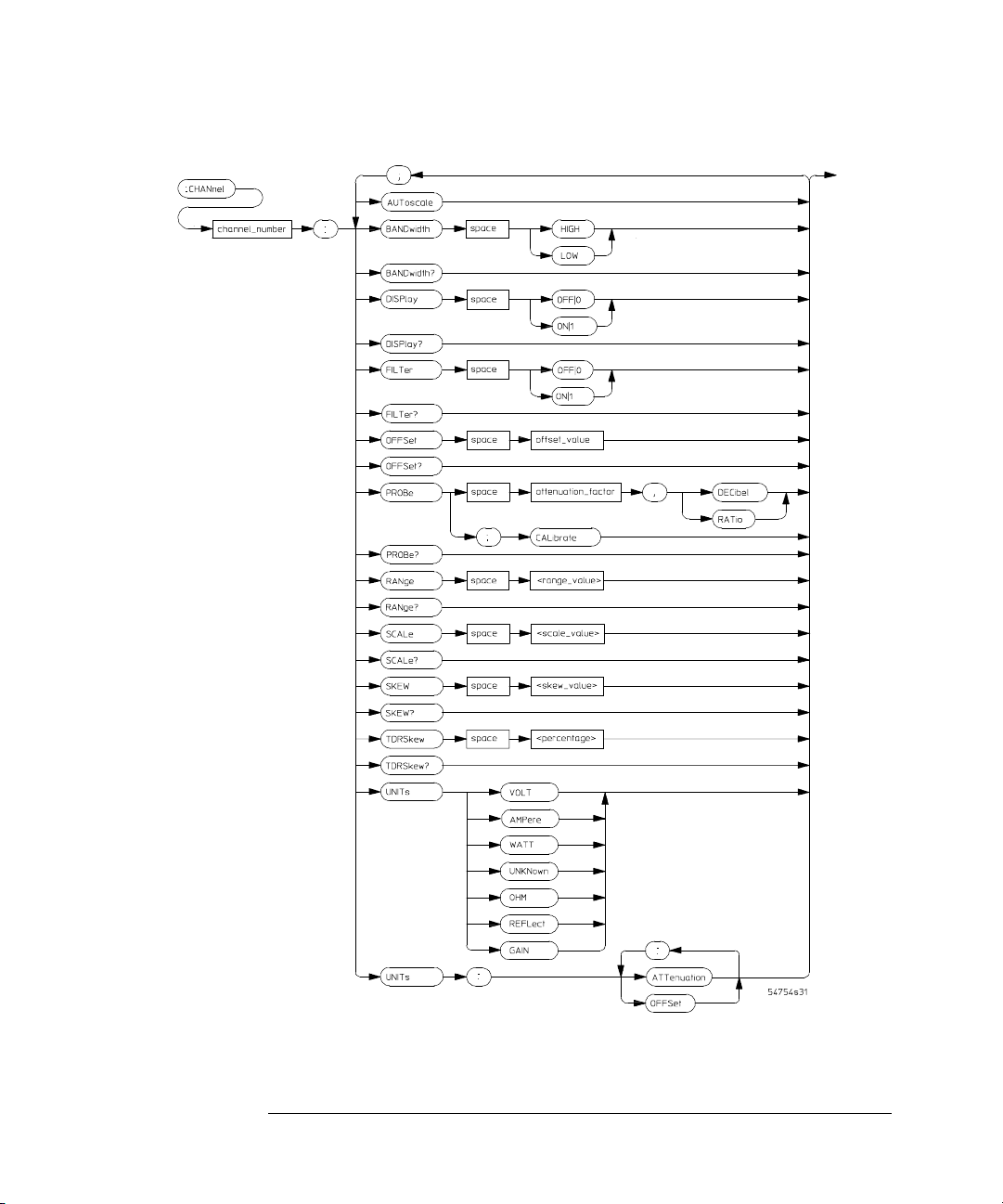
The CHANnel subsystem commands control all vertical (Y axis)
functions of the oscilloscope. The options for the channel subsystem
commands vary depending on which plug-in you are using.
The channel displays may be toggled on and off with the root level
commands VIEW and BLANk.
The TDR plug-in modifies the operation of the following channel
commands:
OFFSet
•
RANGe
•
SCALe
•
TDRSkew
•
UNITs
•
5–2
Page 33
Channel Commands
Channel Subsystem Commands Syntax Diagram
5–3
Page 34

Channel Commands
OFFSet
OFFSet
Command
<number>
<offset_value>
Example
:CHANnel<number>:OFFSet <offset_value>
Sets the voltage that is representated at center screen (two divisions from
the bottom for optical channels) for the selected channel. Offset parameters
are plug-in, probe, and vertical scale dependent.
For TDR and TDT applications, when the TDR stimulus is set to differential
or common mode, or when OHM, REFLect, or GAIN units are selected, the
instrument will change offset to magnify offset. This command is used to set
the magnify offset as well as the offset.
An integer, 1 through 4, indicating the slot in which the channel resides,
followed by an optional A or B identifying which of two possible channels in
the slot is being referenced.
Offset value at center screen. Usually expressed in volts, but could be in
other measurement units, such as amperes, if you have specified other units
using the CHANnel:UNITs command.
The following example sets the offset for channel 1 to 125 mV:
10 OUTPUT 707;":CHANNEL1:OFFSET 125 MV"
20 END
Query
Returned Format
:CHANnel<number>:OFFSet?
The query returns the current offset value for the specified channel.
[:CHANnel<number>:OFFSet]<offset_value><NL>
5–4
Page 35

Channel Commands
RANGe
Example
Command
The following example places the offset value of channel 1 into the string
variable Offset$, then prints the contents of that variable to the controller’s
screen:
10 DIM Offset$[50]
20 OUTPUT 707;":CHANNEL1:OFFSET?"
30 ENTER 707;Offset$
40 PRINT Offset$
50 END
RANGe
:CHANnel<number>:RANGe <range_value>
Defines the full-scale vertical axis of the selected channel. It sets up
acquisition and display hardware to display the waveform at a given range
scale. The values represent the full-scale deflection factor of the vertical axis
in volts. These values change as the probe attenuation factor is changed.
For TDR and TDT applications, when the TDR stimulus is set to differential
or common mode, or when OHM, REFLect, or GAIN units are selected, the
instrument will change scale to magnify scale. This command is used to set
the magnify range as well as the range.
<number>
<range_value>
Example
An integer, 1 through 4, indicating the slot in which the channel resides,
followed by an optional A or B identifying which of two possible channels in
the slot is being referenced.
Full-scale voltage of the specified channel number. Available ranges are
dependent on the plug-in and attenuation factor.
The following example sets the full-scale range for channel 1 to 500 mV:
10 OUTPUT 707;":CHANNEL1:RANGE 500 MV"
20 END
5–5
Page 36

Channel Commands
SCALe
Query
Returned Format
Example
Command
:CHANnel<number>:RANGe?
The query returns the current full-scale vertical axis setting for the selected
channel.
[:CHANnel<number>:RANGe]<range_value><NL>
The following example places the range value of channel 1 into the string
variable Range$, then prints the contents of that variable to the controller’s
screen:
10 DIM Range$[50]
20 OUTPUT 707;":CHANNEL1:RANGE?"
30 ENTER 707;Range$
40 PRINT Range$
50 END
SCALe
:CHANnel<number>:SCALe <scale_value>
<number>
<scale_value>
Defines the vertical scale of the channel in units per division. This command
is the same as the front-panel channel scale.
For TDR and TDT applications, when the TDR stimulus is set to differential
or common mode, or when OHM, REFLect, or GAIN units are selected, the
instrument will change scale to magnify scale. This command is used to set
the magnify scale as well as the scale.
An integer, 1 through 4, indicating the slot in which the channel resides,
followed by an optional A or B identifying which of two possible channels in
the slot is being referenced.
Vertical scale of the channel in units per division.
5–6
Page 37

Channel Commands
SCALe
Example
Query
Returned Format
Example
The following example sets the scale for channel 1 to 500 mV:
10 OUTPUT 707;":CHANNEL1:SCALE 500 MV"
20 END
:CHANnel<number>:SCALe?
The query returns the current scale setting for the specified channel.
[:CHANnel<number>:SCALe]<scale_value><NL>
The following example places the scale value of channel 1 into the string
variable Scale$, then prints the contents of that variable to the controller’s
screen:
10 DIM Scale$[50]
20 OUTPUT 707;":CHANNEL1:SCALE?"
30 ENTER 707;Scale$
40 PRINT Scale$
50 END
5–7
Page 38

Channel Commands
TDRSkew
TDRSkew
Command
<number>
<percent>
Example
Query
Returned Format
:CHANnel<number>:TDRSkew <percent> [%]
This command sets the TDR skew for the given channel. The TDR skew
control moves the TDR step relative to the trigger position. The control may
be set from -100 to 100 percent of the allowable range. This command is only
applicable to TDR channels.
An integer, 1 through 4, indicating the slot in which the channel resides,
followed by an optional A or B identifying which of two possible channels in
the slot is being referenced.
A number between -100 and 100, used to set the step position.
The following example sets the TDR skew for channel 1 to 20%:
10 OUTPUT 707;":CHANNEL1:TDRSKEW 20"
20 END
:CHANnel<number>:TDRSkew?
The query returns the current TDR skew setting for the specified channel.
This query returns the TDR skew value in percent of allowable range from
-100 to 100 percent. This command is only applicable to TDR channels.
The returned format is a real number.
5–8
Page 39

UNITs
Channel Commands
UNITs
Command
Example
Query
<number>
:CHANnel<number>:UNITs {VOLT | AMPere | WATT |
UNKNown | OHM | REFLect | GAIN}
Allows you to work in vertical units other than volts. The units command
changes the name of the Y-axis units from VOLT to AMPere, WATT, or
UNKNown. The units are implied for other pertinent channel commands,
such as RANGe and OFFSet.
For TDR and TDT applications, you can also select the units OHM, REFLect,
and GAIN. OHM and REFLect may be selected for TDR channels, while GAIN
may be selected for TDT channels. You must establish the normalization and
reference plane to select these units. ee the
for establishing the reference plane.
An integer, 1 through 4, indicating the slot in which the channel resides,
followed by an optional A or B identifying which of two possible channels in
the slot is being referenced.
The following example sets the units for channel 1 to ohms:
10 OUTPUT 707;":CHANNEL1:UNITS OHM"
20 END
54753 Front Panel Guide
:CHANnel<number>:UNITs?
Returned Format
The query returns the current units setting for the specified channel.
[:CHANnel<number>:UNITs]{VOLT | AMPere | WATT | UNKNown | OHM |
REFLect | GAIN}<NL>
5–9
Page 40

Channel Commands
UNITs
Example
The following example places the vertical units for the specified channel into
the string variable Units$, then prints the contents of that variable to the
controller’s screen:
10 DIM Units$[50]
20 OUTPUT 707;":CHANNEL:UNITS?"
30 ENTER 707;Units$
40 PRINT Units$
50 END
5–10
Page 41
6
Disk Commands
Page 42
Disk Commands
The DISK subsystem commands perform the disk operations as
defined under the disk menu of the front panel. This allows storage
and retrieval of waveforms, setups and pixel memory, as well as
formatting the disk.
The filenames used are compatible with MS-DOS. They consist of up
to 8 characters for the name with a 0 to 3 character extension,
separated by a "." (dot). File names are all upper case but can be
entered in either upper or lower case; they will be forced to upper
case internally. Valid characters are [A-Z, 0-9, _ (the underscore
character)].
N O T E
The filename must be enclosed in quotes in the disk commands.
The TDR plug-in modifies the operation of the following disk
commands:
LOAD
•
STORe
•
6–2
Page 43
Disk Commands
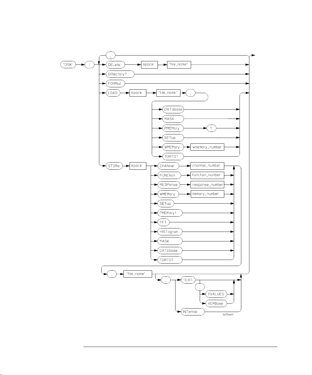
Disk Subsystem Command Syntax Diagram
6–3
Page 44

Disk Commands
LOAD
LOAD
Command
<filename>
Example
<source>
<number>
:DISK:LOAD "<filename>", <source>
Loads a setup, waveform, database, mask, TDR/TDT calibration, or pixel
memory from the disk. The filename does not include a suffix. The suffix
supplied by the instrument depends on the source and file format specified.
The TDRTDT option is a file type choice used to load TDR/TDT calibration
values into the instrument.
{DATabase | MASK | PMEMory 1 | SETup |
WMEMory<number> | TDRTDT}
Is an MS-DOS compatible file name up to 8 characters long.
Represents waveforms 1, 2, 3, or 4.
The following example loads the file "CALIBR" which contains the TDR/TDT
calibrations:
10 OUTPUT 707;":DISK:LOAD "CALIBR", TDRTDT
20 END
6–4
Page 45
STORe
Disk Commands
STORe
Command
<filename>
<source>
<number>
<format>
:DISK:STORe <source>, "<filename>"[,<format>]
Stores a setup, waveform, database, mask, TDR response, TDR/TDT
calibration, or pixel memory to the disk. The filename does not include a
suffix. The suffix is supplied by the instrument depending on the source and
file format specified. The database may only be saved in internal format. The
TDRTDT option is a file type choice used to store the instrument’s TDR/TDT
calibration values.
{CHANnel<number> | FUNCtion<number> |
WMEMory<number> | SETup | PMEMory1 | HISTogram |
DATabase | FFT | MASK | RESPonse<number> | TDRTDT}
For channels: 1, 2, 3, or 4, optionally followed by A or B. For functions: 1 or 2.
For waveforms: 1, 2, 3, or 4. For responses: 1, 2, 3, or 4.
Is an MS-DOS compatible file name up to 8 characters long.
{TEXT [,YVALues | VERBose] | INTernal}
N O T E
The format field is for waveforms. The default is INTernal. In TEXT mode, y
values may be specified so that only Y values are stored. VERBose is the default
in which Y values and the waveform preamble are stored. See the WAVeform
Commands chapter in the 54750/83480 Programmer’s Guide for
information on converting data to values.
Example
The following examples stores TDR response 4 in the file named
NEWRESP.RSP:
10 OUTPUT 707;":DISK:STORE RESPONSE4,""NEWRESP.RSP"""
20 END
6–5
Page 46

6–6
Page 47
7
Display Commands
Page 48

Display Commands
The DISPlay subsystem controls the display of data, markers, text,
and graticules, and also controls the use of color.
The display mode is selected by the ACQuire:TYPe command. The
number of averages is selected by the ACQuire:COUNt command.
The TDR plug-in module modifies the operation of the following
DISPlay subsystem command:
ASSign
•
7–2
Page 49
Display Commands
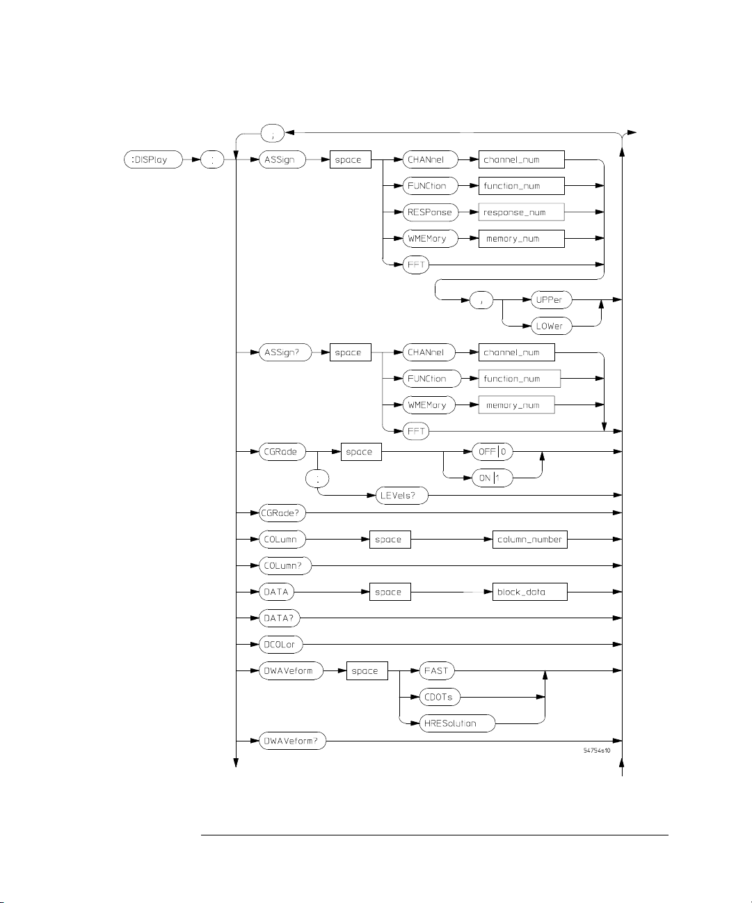
Display Subsystem Command Syntax Diagram
7–3
Page 50
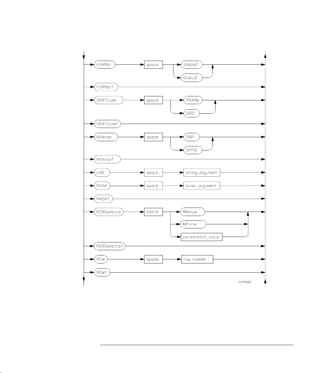
Display Commands
Display Subsystem Command Syntax Diagram (continued)
7–4
Page 51
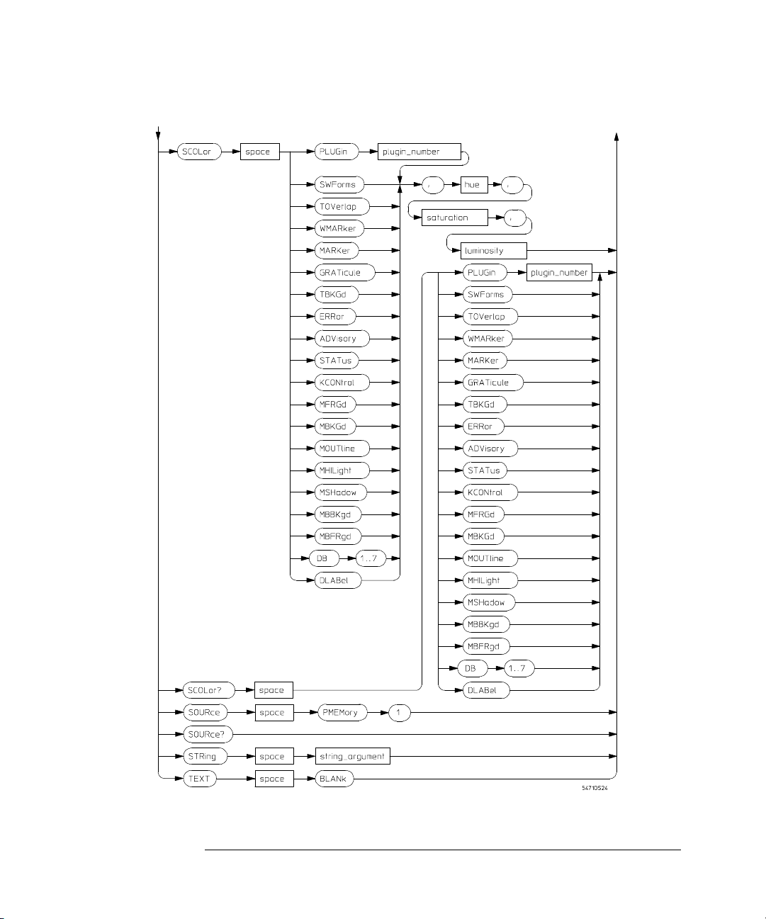
Display Commands
Display Subsystem Command Syntax Diagram (continued)
7–5
Page 52

Display Commands
ASSign
ASSign
Command
Example
Query
<number>
:DISPlay:ASSign {CHANnel<number> |
FUNCtion<number> | RESPonse<number> |
WMEMory<number> | FFT},{UPPer | LOWer}
Assigns the specified channel, waveform, function, TDR response, or FFT to
a particular portion of the waveform area on the screen. This command has
no effect when the graticule format is single.
For channels: an integer, 1 through 4, indicating the slot in which the channel
resides, followed by an optional A or B identifying which of two possible
channels in the slot is being referenced. For functions: 1 or 2. For waveform
memories (WMEMory): 1, 2, 3, or 4. For TDR responses: 1, 2, 3, or 4.
The following example assigns TDR response 1 to the upper portion of the
oscilloscope screen.
10 OUTPUT 707;":DISPLAY:ASSIGN RESPONSE1,UPPER"
20 END
:DISPlay:ASSign? {CHANnel<number> |
FUNCtion<number> | RESPonse<number> |
WMEMory<number> | FFT}
Returned Format
The query returns the portion of the waveform area where the specified
waveform is displayed or was last displayed if it is not currently on screen.
[:DISPlay:ASSign? {CHANnel<number> | FUNCtion<number> |
RESPonse<number> | WMEMory<number> | FFT}]{UPPer | LOWer}<NL>
7–6
Page 53

Display Commands
ASSign
Example
The following example returns the portion of the waveform area where the
TDR response 1 waveform resides to the string variable Setting$, then prints
it to the controller’s screen.
10 DIM Setting$[50] !Dimension variable
20 OUTPUT 707;":DISPLAY:ASSIGN? RESPONSE1"
30 ENTER 707;Setting$
40 PRINT Setting$
50 END
7–7
Page 54

7–8
Page 55
8
Function Commands
Page 56

Function Commands
The FUNCtion subsystem defines two functions, function 1 and
function 2. The operands of these two functions can be any installed
channels in the oscilloscope, TDR responses, waveform memories 1
through 4, a function definition, or a constant.
The A.02.00 firmware revision to the FUNCtion subsystem modifies
the following commands:
ADD
•
BWLimit
•
DIFFerentiate
•
DIVide
•
FFTMagnitude
•
INTegrate
•
INVert
•
MAGNify
•
MAXimum
•
MINimum
•
MULTiply
•
SUBTract
•
VERSus
•
8–2
Page 57
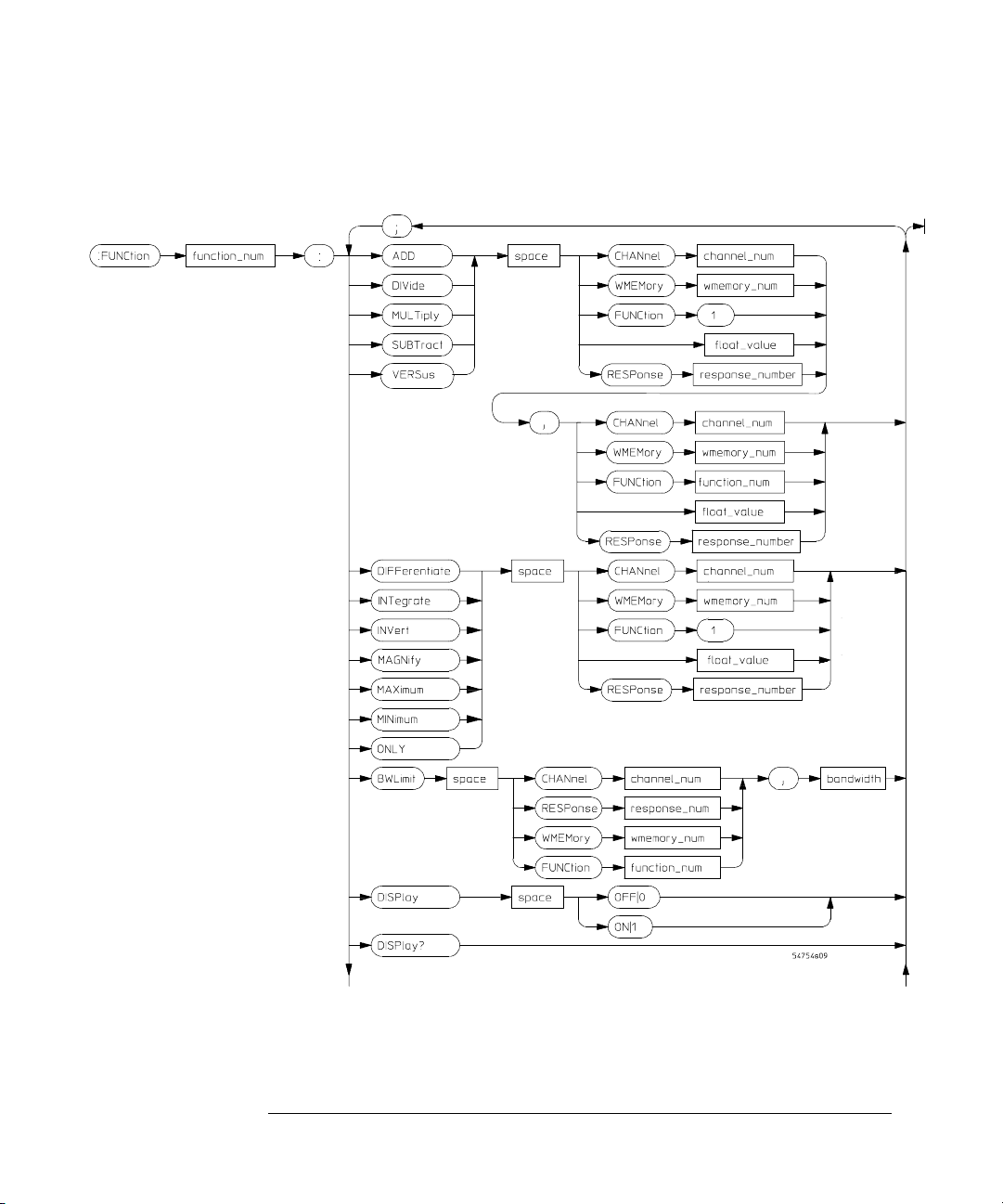
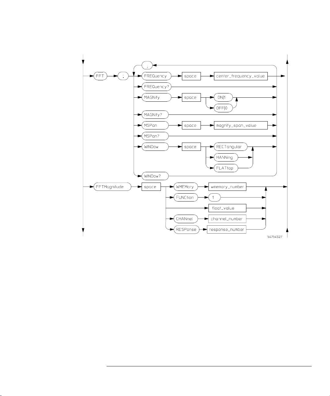
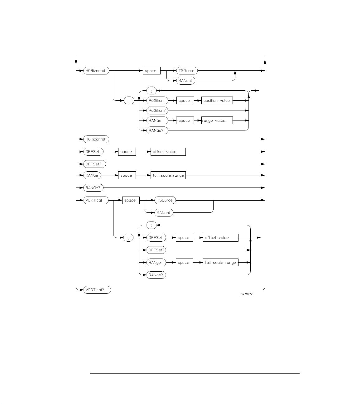
Function Commands
Function Subsystem Command Syntax Diagram
8–3
Page 58
Function Commands
Function Subsystem Command Syntax Diagram (continued)
8–4
Page 59
Function Commands
Function Subsystem Command Syntax Diagram (continued)
8–5
Page 60

Function Commands
ADD
ADD
Command
<source>
<number>
<float_value>
Example
:FUNCtion{1 | 2}:ADD <source>[,<source>]
Defines a function that takes the algebraic sum of two defined operands.
{CHANnel<number> | FUNCtion<number> |
RESPonse<number> | WMEMory<number> |
<float_value>}
For channels: an integer, 1 through 4, indicating the slot in which the channel
resides, followed by an optional A or B identifying which of two possible
channels in the slot is being referenced. For functions: 1. For waveform
memories (WMEMory): 1, 2, 3, or 4. For TDR responses: 1, 2, 3, or 4.
A real number.
The following example sets up function 1 to add channel 1 to channel 2:
10 OUTPUT 707;":FUNCTION1:ADD CHANNEL1,CHANNEL2"
20 END
BWLimit
Command
:FUNCtion{1 | 2}:BWLimit {{CHANnel<number> |
FUNCtion<number> | RESPonse<number> |
WMEMory<number>}, <bandwidth>}
Provides a bandwidth limit filter function. You can use this function on
waveforms to limit the bandwidth of the signal. In TDR or TDT applications
where the accuracy of normalization is not required, you can use this to
simulate a bandlimited signal through a device under test.
8–6
Page 61

Function Commands
DIFFerentiate
<number>
<bandwidth>
Example
Command
<number>
For channels: an integer, 1 through 4, indicating the slot in which the channel
resides, followed by an optional A or B identifying which of two possible
channels in the slot is being referenced. For functions: 1 or 2. For waveform
memories (WMEMory): 1, 2, 3, or 4. For TDR responses: 1, 2, 3, or 4.
Real number indicating frequency limit for the specified function.
The following example defines function 1 as a bandwidth limit for TDR
response 1 of 100 MHz:
10 OUTPUT 707;":FUNCTION1:BWLIMIT RESPONSE1,100 MHZ"
20 END
DIFFerentiate
:FUNCtion{1 | 2}:DIFFerentiate {CHANnel<number> |
FUNCtion<number> | RESPonse<number> |
WMEMory<number> | <float_value>}
Computes the discrete derivative of the defined operand’s waveform.
For channels: an integer, 1 through 4, indicating the slot in which the channel
resides, followed by an optional A or B identifying which of two possible
channels in the slot is being referenced. For functions: 1. For waveform
memories (WMEMory): 1, 2, 3, or 4. For TDR responses: 1, 2, 3, or 4.
<float_value>
Example
A real number.
The following example sets up function 1 to take the discrete derivative of
the signal on channel 2:
10 OUTPUT 707;":FUNCTION1:DIFFERENTIATE CHANNEL2"
20 END
8–7
Page 62

Function Commands
DIVide
DIVide
Command
<source>
<number>
<float_value>
Example
:FUNCtion{1 | 2}:DIVide <source>[,<source>]
Defines a function that divides the first operand by the second operand.
{CHANnel<number> | FUNCtion<number> |
RESPonse<number> | WMEMory<number> |
<float_value>}
For channels: an integer, 1 through 4, indicating the slot in which the channel
resides, followed by an optional A or B identifying which of two possible
channels in the slot is being referenced. For functions: 1. For waveform
memories (WMEMory): 1, 2, 3, or 4. For TDR responses: 1, 2, 3, or 4.
A real number.
The following example sets up function 1 to divide the signal on channel 1 by
the signal in waveform memory 4:
10 OUTPUT 707;":FUNCTION1:DIVIDE CHANNEL1,WMEMORY4"
20 END
FFTMagnitude
Command
<number>
<float_value>
:FUNCtion{1 | 2}:FFTMagnitude {CHANnel<number> |
FUNCtion<number> | RESPonse<number> |
WMEMory<number> | <float_value>}
Defines a function that computes the FFT magnitude.
For channels: an integer, 1 through 4, indicating the slot in which the channel
resides, followed by an optional A or B identifying which of two possible
channels in the slot is being referenced. For functions: 1. For waveform
memories (WMEMory): 1, 2, 3, or 4. For TDR responses: 1, 2, 3, or 4.
A real number.
8–8
Page 63

Function Commands
INTegrate
Example
Command
<number>
<float_value>
Example
The following example computes the FFTmagnitude for channel 1:
10 OUTPUT 707;":FUNCTION1:FFTMAGNITUDE CHANNEL1"
20 END
INTegrate
:FUNCtion{1 | 2}:INTegrate {CHANnel<number> |
FUNCtion<number> | RESPonse<number> |
WMEMory<number> | <float_value>}
Defines a function that computes the integral of the defined operand’s
waveform.
For channels: an integer, 1 through 4, indicating the slot in which the channel
resides, followed by an optional A or B identifying which of two possible
channels in the slot is being referenced. For functions: 1. For waveform
memories (WMEMory): 1, 2, 3, or 4. For TDR responses: 1, 2, 3, or 4.
A real number.
The following example sets up function 1 to compute the integral of
waveform memory 3:
10 OUTPUT 707;":FUNCTION1:INTEGRATE WMEMORY3"
20 END
8–9
Page 64

Function Commands
INVert
INVert
Command
<number>
<float_value>
Example
Command
:FUNCtion{1 | 2}:INVert {CHANnel<number> |
FUNCtion<number> | RESPonse<number> |
WMEMory<number> | <float_value>}
Defines a function that inverts the defined operand’s waveform by
multiplying by -1.
For channels: an integer, 1 through 4, indicating the slot in which the channel
resides, followed by an optional A or B identifying which of two possible
channels in the slot is being referenced. For functions: 1. For waveform
memories (WMEMory): 1, 2, 3, or 4. For TDR responses: 1, 2, 3, or 4.
A real number.
The following example sets up function 1 to invert the signal on channel 1:
10 OUTPUT 707;":FUNCTION1:INVERT CHANNEL1"
20 END
MAGNify
:FUNCtion{1 | 2}:MAGNify {CHANnel<number> |
FUNCtion<number> | RESPonse<number> |
WMEMory<number> | <float_value>}
Defines a function that is a copy of the operand. The magnify function is a
software magnify. No hardware settings are altered as a result of using this
function. It is useful for scaling channels, another function, TDR/TDT
responses and memories with the RANGE and OFFSET commands in this
subsystem.
Magnify performs the same operation as the "ONLY" operator, and is the
preferred operator of the two. "ONLY" is included in this instrument for
compatibility with previous instruments.
8–10
Page 65

Function Commands
MAXimum
<number>
<float_value>
Example
Command
<number>
For channels: an integer, 1 through 4, indicating the slot in which the channel
resides, followed by an optional A or B identifying which of two possible
channels in the slot is being referenced. For functions: 1. For waveform
memories (WMEMory): 1, 2, 3, or 4. For TDR responses: 1, 2, 3, or 4.
A real number.
The following example creates a function (function 1) that is a magnified
copy of channel 1:
10 OUTPUT 707;":FUNCTION1:MAGNIFY CHANNEL1"
20 END
MAXimum
:FUNCtion{1 | 2}:MAXimum {CHANnel<number> |
FUNCtion<number> | RESPonse<number> |
WMEMory<number> | <float_value>}
Defines a function that computes the maximum value of the operand
waveform in each time bucket.
For channels: an integer, 1 through 4, indicating the slot in which the channel
resides, followed by an optional A or B identifying which of two possible
channels in the slot is being referenced. For functions: 1. For waveform
memories (WMEMory): 1, 2, 3, or 4. For TDR responses: 1, 2, 3, or 4.
<float_value>
Example
A real number.
The following example sets up function 1 to compute the maximum of each
time bucket for channel 1:
10 OUTPUT 707;":FUNCTION1:MAXIMUM CHANNEL1"
20 END
8–11
Page 66

Function Commands
MINimum
MINimum
Command
<number>
<float_value>
Example
Command
:FUNCtion{1 | 2}:MINimum {CHANnel<number> |
FUNCtion<number> | RESPonse<number> |
WMEMory<number> | <float_value>}
Defines a function that computes the minimum of each time bucket for the
defined operand’s waveform.
For channels: an integer, 1 through 4, indicating the slot in which the channel
resides, followed by an optional A or B identifying which of two possible
channels in the slot is being referenced. For functions: 1. For waveform
memories (WMEMory): 1, 2, 3, or 4. For TDR responses: 1, 2, 3, or 4.
A real number.
The following example sets up function 1 to compute the minimum of each
time bucket for channel 1:
10 OUTPUT 707;":FUNCTION1:MINIMUM CHANNEL1"
20 END
MULTiply
:FUNCtion{1 | 2}:MULTiply <source>[,<source>]
<source>
<number>
Defines a function that algebraically multiplies the first operand by the
second operand.
{CHANnel<number> | FUNCtion<number> |
RESPonse<number> | WMEMory<number> |
<float_value>}
For channels: an integer, 1 through 4, indicating the slot in which the channel
resides, followed by an optional A or B identifying which of two possible
channels in the slot is being referenced. For functions: 1. For waveform
memories (WMEMory): 1, 2, 3, or 4. For TDR responses: 1, 2, 3, or 4.
8–12
Page 67

Function Commands
SUBTract
<float_value>
Example
Command
<source>
<number>
A real number.
The following example defines a function that multiplies channel 1 by
waveform memory 1:
10 OUTPUT 707;":FUNCTION1:MULTIPLY CHANNEL1,WMEMORY1"
20 END
SUBTract
:FUNCtion{1 | 2}:SUBTract <source>[,<source>]
Defines a function that algebraically subtracts the second operand from the
first operand.
{CHANnel<number> | FUNCtion<number> |
RESPonse<number> | WMEMory<number> |
<float_value>}
For channels: an integer, 1 through 4, indicating the slot in which the channel
resides, followed by an optional A or B identifying which of two possible
channels in the slot is being referenced. For functions: 1. For waveform
memories (WMEMory): 1, 2, 3, or 4. For TDR responses: 1, 2, 3, or 4.
<float_value>
Example
A real number.
The following example defines a function that subtracts waveform memory 1
from channel 1:
10 OUTPUT 707;":FUNCTION1:MULTIPLY CHANNEL1,WMEMORY1"
20 END
8–13
Page 68

Function Commands
VERSus
VERSus
Command
<source>
<number>
<float_value>
Example
:FUNCtion{1 | 2}:VERSus <source>[,<source>]
Defines a function for an X-versus-Y display. The first operand defines the
Y axis and the second defines the X axis. The Y-axis range and offset are
initially equal to that of the first operand and can be adjusted with the
RANGE and OFFSET commands.
{CHANnel<number> | FUNCtion<number> |
RESPonse<number> | WMEMory<number> |
<float_value>}
For channels: an integer, 1 through 4, indicating the slot in which the channel
resides, followed by an optional A or B identifying which of two possible
channels in the slot is being referenced. For functions: 1. For waveform
memories (WMEMory): 1, 2, 3, or 4. For TDR responses: 1, 2, 3, or 4.
A real number.
The following example defines function 1 as an X-versus-Y display. Channel 1
is the X axis and waveform memory 2 is the Y axis:
10 OUTPUT 707;":FUNCTION1:VERSUS WMEMORY2,CHANNEL1"
20 END
8–14
Page 69
9
Histogram Commands
Page 70

Histogram Commands
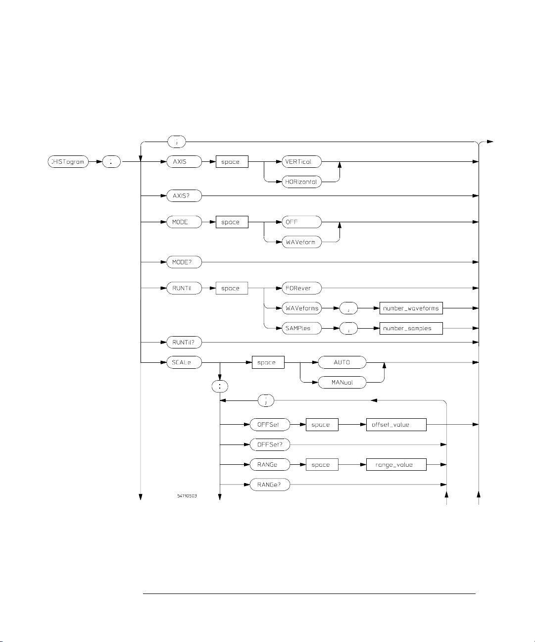
The HISTogram commands and queries control the histogram features
of the oscilloscope. A histogram shows the probability distribution of
acquired data within a user-defined histogram window. You can
display the histogram vertically for voltage measurements or
horizontally for timing measurements.
The most common use for histograms is measuring and characterizing
noise or jitter on displayed waveforms. Noise is measured by sizing the
histogram window to a narrow portion of time and observing a vertical
histogram that shows the noise on the waveform. Jitter is measured by
sizing the histogram window to a narrow portion of voltage and
observing a horizontal histogram that shows the jitter on an edge.
The TDR plug-in modifies the operation of the following HISTogram
subsystem command:
WINDow:SOURce
•
9–2
Page 71
Histogram Commands
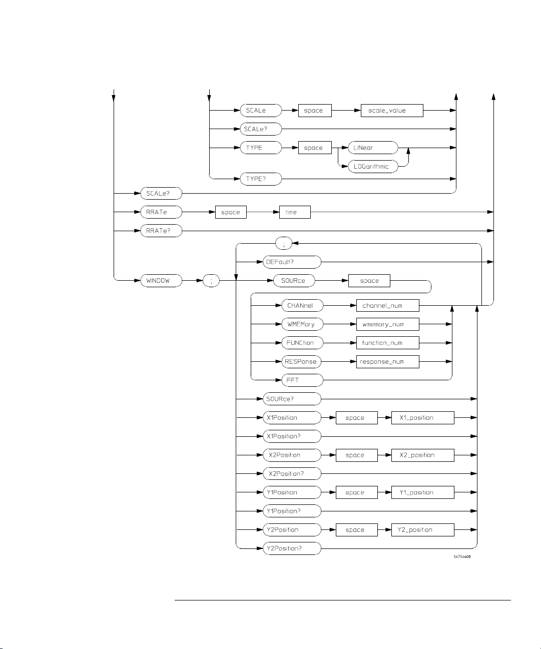
Histogram Subsystem Command Syntax Diagram
9–3
Page 72
Histogram Commands
Histogram Subsystem Command Syntax Diagram (continued)
9–4
Page 73

WINDow:SOURce
Histogram Commands
WINDow:SOURce
Command
<number>
Example
Query
Returned Format
:HISTogram:WINDow:SOURce {CHANnel<number> |
FUNCtion<number> | RESPonse<number> |
WMEMory<number> | FFT}
Selects the source of the histogram window. The histogram window will track
the source’s vertical and horizontal scale.
For channels: an integer, 1 through 4, indicating the slot in which the channel
resides, followed by an optional A or B identifying which of two possible
channels in the slot is being referenced. For functions: 1 or 2. For waveform
memories (WMEMory): 1, 2, 3, or 4. For TDR response: 1, 2, 3, or 4.
The following example sets the histogram window’s source to TDR
response 1:
10 OUTPUT 707;":HISTOGRAM:WINDOW:SOURCE RESPONSE1"
20 END
:HISTogram:WINDow:SOURce?
The query returns the currently selected histogram window source.
[:HISTogram:WINDow:SOURce]{CHANnel<number> | FUNCtion<number>
| RESPonse<number> | WMEMory<number> | FFT}<NL>
Example
The following example returns the result of the window source query and
prints it to the controller’s screen.
10 DIM Winsour$[50] !Dimension variable
20 OUTPUT 707;":HISTOGRAM:WINDOW:SOURCE?"
30 ENTER 707;Winsour$
40 PRINT Winsour$
50 END
9–5
Page 74

9–6
Page 75
10
Limit Test Commands
Page 76

Limit Test Commands
The Limit Test commands and queries control the limit test features
of the oscilloscope. Limit testing automatically compares
measurement results with pass or fail limits. The limit test tracks up to
four measurements. This command subsystem also controls the
actions that are taken when a test fails.
The TDR plug-in modifies the operation of the following Limit Test
subsystem command:
SWAVeform
•
10–2
Page 77
Limit Test Commands
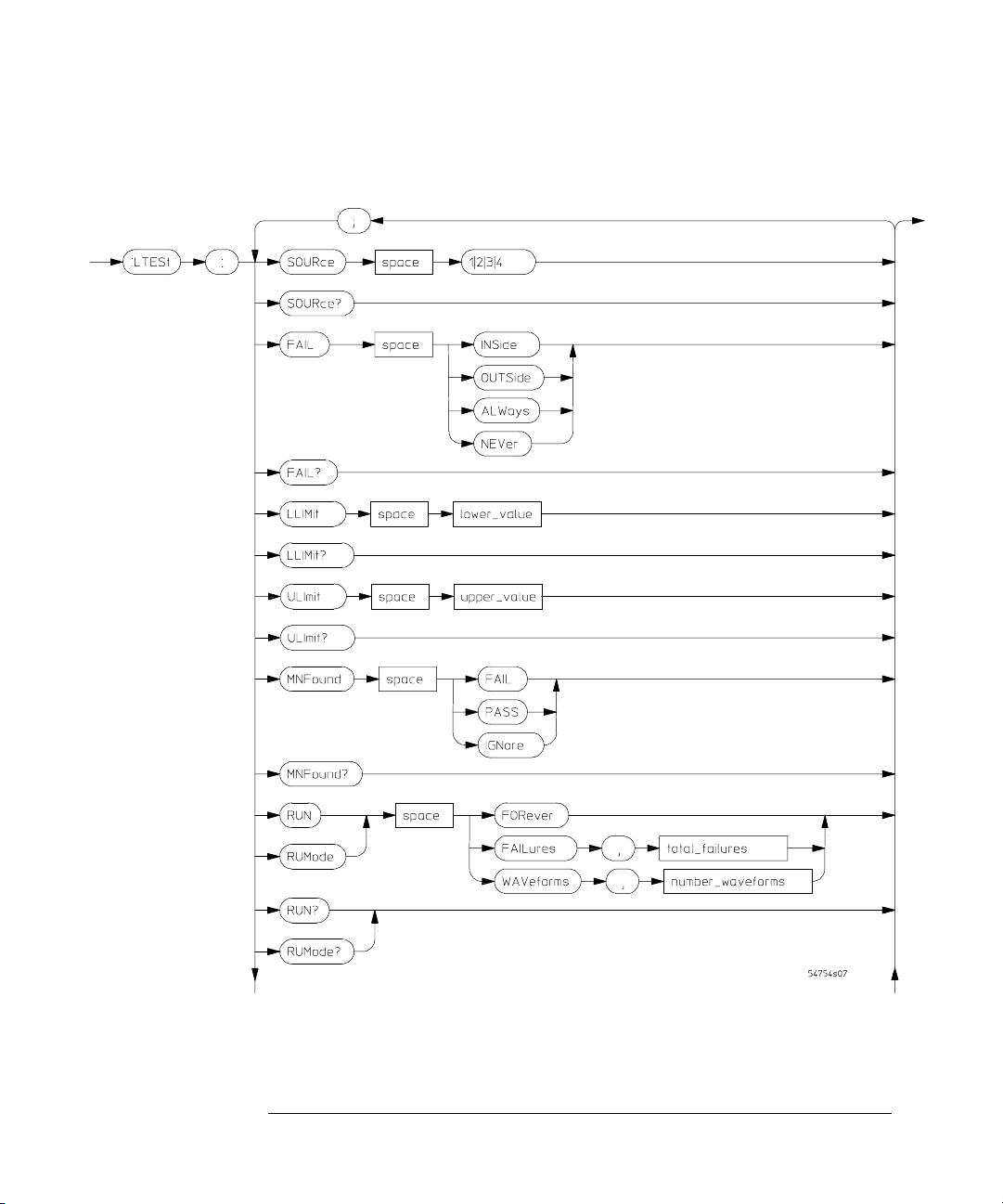
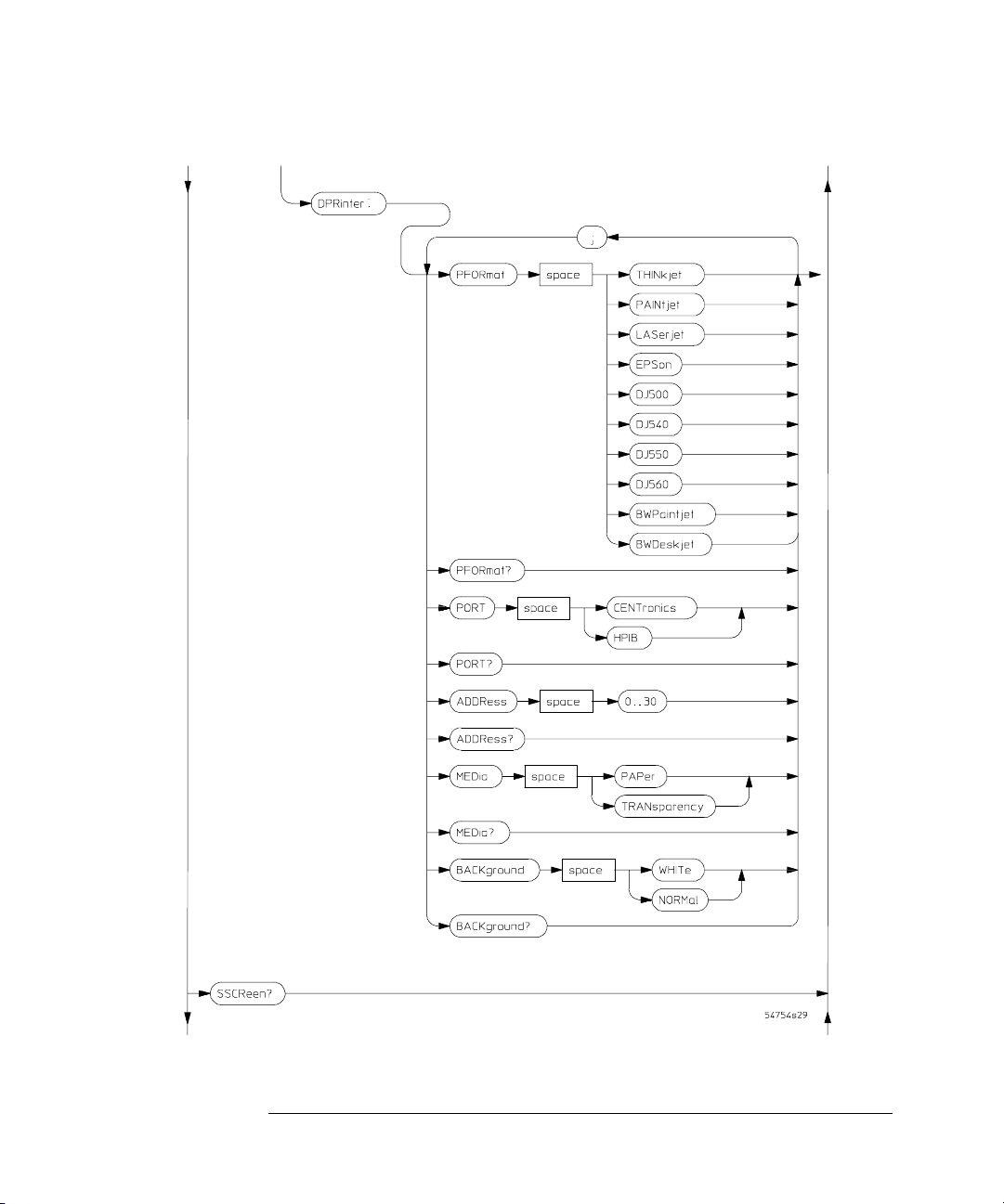
Limit Test Subsystem Command Syntax Diagram
10–3
Page 78
Limit Test Commands
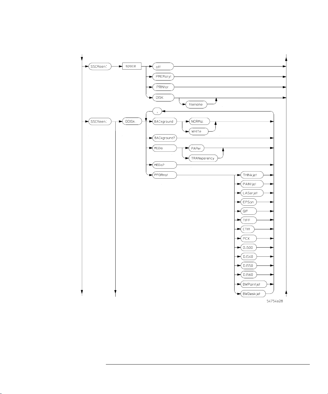
Limit Test Subsystem Command Syntax Diagram (continued)
10–4
Page 79
Limit Test Commands
Limit Test Subsystem Command Syntax Diagram (continued)
10–5
Page 80
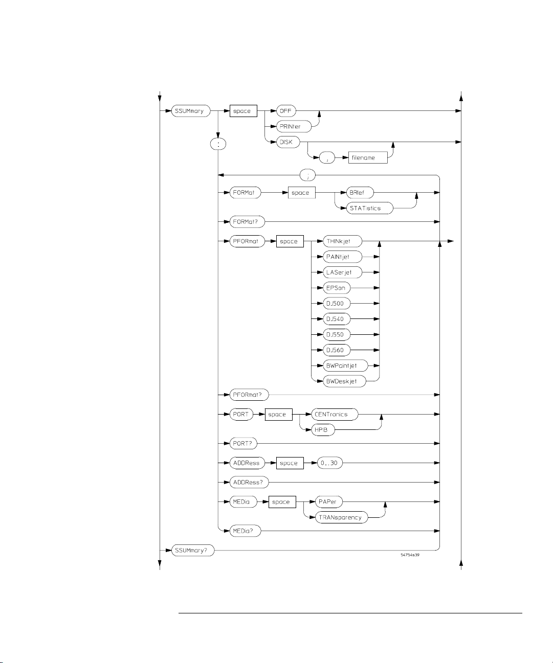
Limit Test Commands
Limit Test Subsystem Command Syntax Diagram (continued)
10–6
Page 81
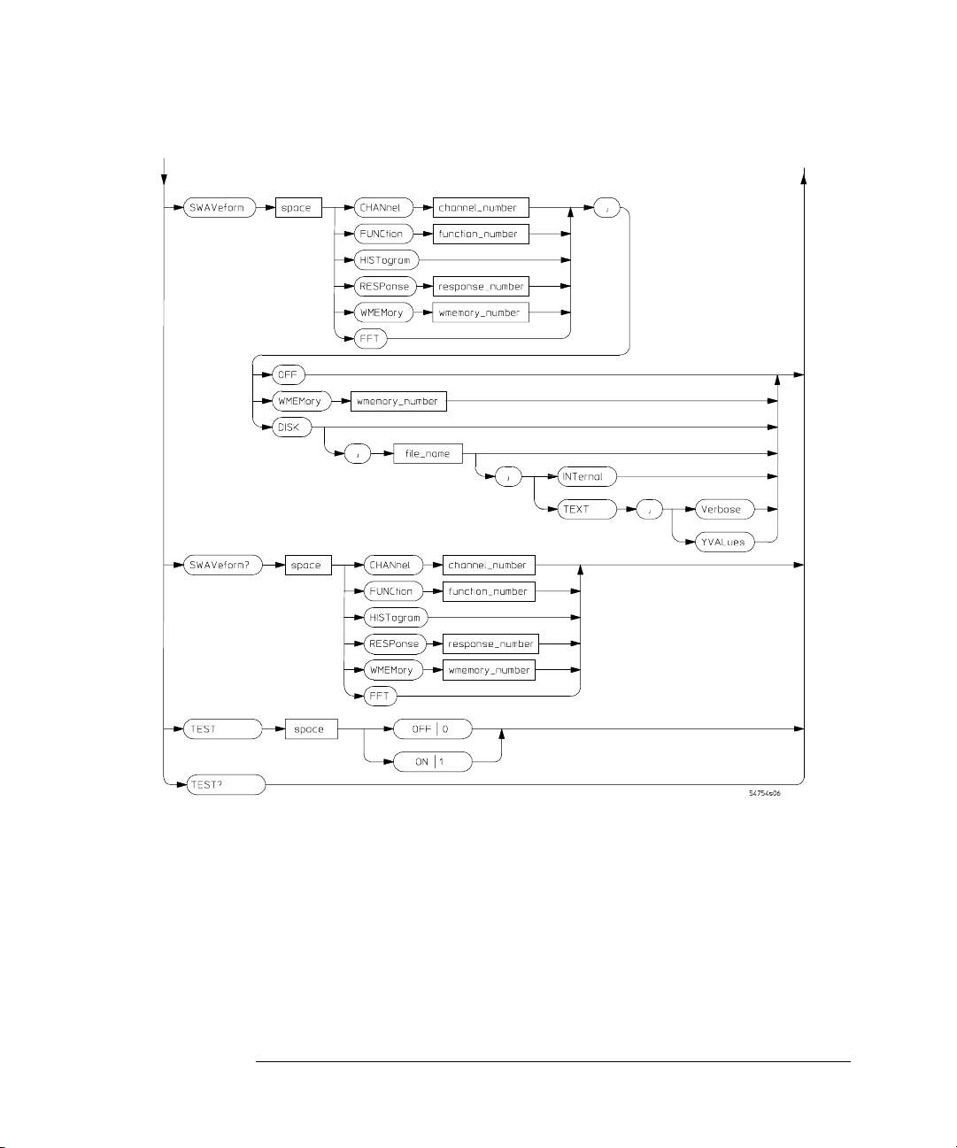
Limit Test Commands
Limit Test Subsystem Command Syntax Diagram (continued)
10–7
Page 82

Limit Test Commands
SWAVeform
SWAVeform
Command
<source>
<destination>
<filename>
<format>
Example
:LTESt:SWAVeform
<source>,<destination>,[,<filename>[,<format>]]
Saves waveforms from a channel, function, histogram, TDR response, or
waveform memory in the event of a failure detected by the limit test. Each
waveform source can be individually specified, allowing multiple channels or
functions to be saved to disk or waveform memories. Setting a particular
source to OFF removes any waveform save action from that source.
{CHANnel<number> | FUNCtion<number> | HISTogram
| RESPonse<number> | WMEMory<number>}
{OFF | WMEMory<number> | DISK}
When DISK is selected, a file name is required.
A descriptive file prefix consisting of up to four characters. If no filename is
specified, the prefix defaults to CH1A..CH4B, FN1, FN2, FFT, HIST,
MEM1..MEM4, RSP1..RSP4.
{TEXT [,YVALues | VERBose] | INTernal}
The following example turns off saving of waveforms from TDR response 1.
10 OUTPUT 707;":LTEST:SWAVEFORM RESP1,OFF"
20 END
10–8
Page 83

Limit Test Commands
SWAVeform
Query
Returned Format
Example
:LTESt:SWAVeform? <source>
The query returns the current save waveform configuration.
:LTESt:SWAVeform <source>,<destination>,[,<filename>[,<format>]]
The following example retrieves the information about where TDR
response 1 will be saved, then displays it on the controller screen:
10 DIM SWAV$[50]
20 OUTPUT 707;":LTEST:SWAVEFORM? RESPONSE1"
30 ENTER 707;SWAV$
40 PRINT SWAV$
50 END
10–9
Page 84

10–10
Page 85
11
Marker Commands
Page 86

Marker Commands
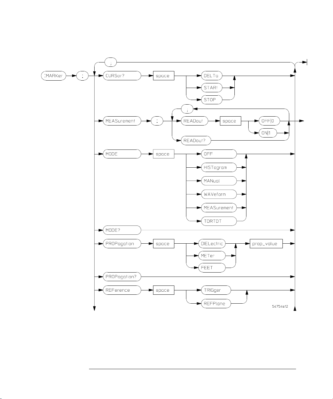
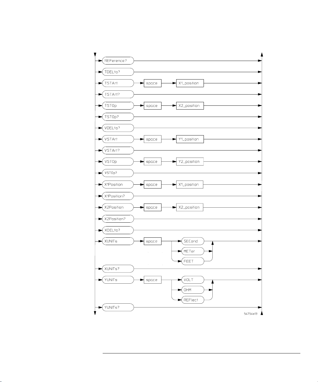
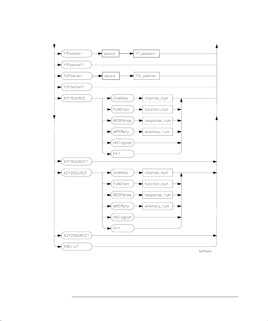
The commands in the MARKER subsystem are used to specify and
query the settings of the time and distance (X-axis) and the current
measurement units (Y-axis) markers. The X-axis measurement units
are typically set using the CHANnel:XUNITs command. The Y-axis
measurement units are typically set using the CHANnel:YUNITs
command.
The TDR plug-in adds the following commands to the Marker
subsystem:
PROPagation
•
REFerence
•
XUNITs
•
YUNITs
•
The TDR plug-in modifies the operation of the following Marker
subsystem commands:
MODE
•
X1Y1source
•
X2Y2source
•
11–2
Page 87
Marker Commands
Marker Subsystem Command Syntax Diagram
11–3
Page 88
Marker Commands
Marker Subsystem Command Syntax Diagram (continued)
11–4
Page 89
Marker Commands
Marker Subsystem Command Syntax Diagram (continued)
11–5
Page 90

Marker Commands
MODE
MODE
Command
Example
Query
Returned Format
Example
:MARKer:MODE {OFF | MANual | WAVeform |
MEASurement | HISTogram | TDRTDT}
Sets the marker mode.
The following example sets the marker mode to TDR/TDT.
10 OUTPUT 707;":MARKER:MODE TDRTDT"
20 END
:MARKer:MODE?
The query returns the current marker mode.
[:MARKer:MODE]{OFF | MANual | WAVeform | MEASurement | HISTogram
| TDRTDT}<NL>
The following example puts the current marker mode into the string variable
Selection$, then prints the contents of the variable to the controller’s screen.
10 DIM Selection$[50] !Dimension variable
20 OUTPUT 707;":MARKER:MODE?"
30 ENTER 707;Section$
40 PRINT Selection$
50 END
11–6
Page 91
PROPagation
Marker Commands
PROPagation
Command
<propagation>
Example
:MARKer:PROPagation {DIELectric | METer | FEET},
<propagation>
Sets the propagation velocity for TDR and TDT measurements. The
propagation may be specified as a dielectric constant or in meters per second
or feet per second. The value is used to determine the distance from the
reference plane in TDR and TDT marker measurements.
N O T E
To ensure accurate marker measurements, you must ensure that the
propagation value is accurate, that the units are set correctly
(:MARKer:XUNITs), and that the correct reference plane is selected
(:MARKer:REFerence).
Dielectric constant or propagation value. You must specify one of the
modifiers DIELectric, METer, or FEET.
The following example sets the propagation to 100,000 feet per second.
10 OUTPUT 707;":MARKER:PROPAGATION FEET, 1E5"
20 END
Query
Returned Format
:MARKer:PROPagation?
The query returns the current propagation value.
[:MARKer:PROPagation]<propagation> {DIELectric | METer |
FEET}<NL>
11–7
Page 92

Marker Commands
REFerence
Example
Command
The following example gets the propagation value from the instrument, puts
it into the variable Prop$, then displays the contents of the variable on the
controller’s screen.
10 DIM Prop$[20] !Declare variable
20 OUTPUT 707;":MARKER:PROPAGATION?"
30 ENTER 707;Prop$
40 PRINT Prop$
50 END
REFerence
:MARKer:REFerence {TRIGger | REFPlane}
Specifies the marker reference for TDR and TDT style markers. If the
reference is TRIGger, then all horizontal axis marker measurements are made
with respect to the trigger point. If the reference is REFPlane, then all
horizontal axis marker measurements are made with respect to the reference
plane. You must perform a normalization and reference plane calibration
before using a reference plane reference. This feature is available only for
TDR and TDT applications.
Example
The following example sets the markers to indicate all horizontal axis
measurements with respect to the trigger:
10 OUTPUT 707;":MARKER:REFERENCE TRIGGER"
20 END
11–8
Page 93

Marker Commands
REFerence
Query
Returned Format
Example
:MARKer:REFerence?
Returns the current reference setting.
[:MARKer:REFerence]{TRIGger | REFPlane}<NL>
The following example puts the current reference setting into the variable
Ref$, then displays the contents of the variable on the controller’s screen.
10 DIM Ref$[20] !Declare variable
20 OUTPUT 707;":MARKER:REFERENCE?"
30 ENTER 707;Ref$
40 PRINT Ref$
50 END
11–9
Page 94

Marker Commands
X1Y1source
X1Y1source
Command
<number>
Example
Query
Returned Format
:MARKer:X1Y1source {CHANnel<number> |
FUNCtion<number> | RESPonse<number> |
WMEMory<number> | HISTogram | FFT}
Sets the source for the X1 and Y1 markers.
For channels: an integer, 1 through 4, indicating the slot in which the channel
resides, followed by an optional A or B indicating which of two possible
channels in the slot is being referenced. For functions: 1 or 2. For waveform
memories (WMEMory): 1, 2, 3, or 4. For TDR response: 1, 2, 3, or 4.
The following example selects TDR response 1 as the X1Y1 source.
10 OUTPUT 707;":MARKER:X1Y1SOURCE RESPONSE1"
20 END
:MARKer:X1Y1source?
The MARKer:X1Y1source query returns the current X1Y1 source.
[:MARKer:X1Y1source] {CHANnel<number> | FUNCTion<number> |
RESPonse<number> | WMEMory<number> | HISTogram | FFT}
Example
The following example returns the current X1Y1 source selection to the
string variable Selection$, then prints the contents of the variable to the
controller’s screen.
10 DIM Selection$[50] !Dimension variable
20 OUTPUT 707;":MARKER:X1Y1SOURCE?"
30 ENTER 707;Selection$
40 PRINT Selection$
50 END
11–10
Page 95

X2Y2source
Marker Commands
X2Y2source
Command
<number>
Example
Query
Returned Format
:MARKer:X2Y2source {CHANnel<number> |
FUNCtion<number> | RESPonse<number> |
WMEMory<number> | HISTogram | FFT}
Sets the source for the X2 and Y2 markers.
For channels: an integer, 1 through 4, indicating the slot in which the channel
resides, followed by an optional A or B indicating which of two possible
channels in the slot is being referenced. For functions: 1 or 2. For waveform
memories (WMEMory): 1, 2, 3, or 4. For TDR response: 1, 2, 3, or 4.
The following example selects TDR response 1 as the X2Y2 source.
10 OUTPUT 707;":MARKER:X2Y2SOURCE RESPONSE1"
20 END
:MARKer:X2Y2source?
The MARKer:X2Y2source query returns the current X2Y2 source.
[:MARKer:X2Y2source] {CHANnel<number> | FUNCTion<number> |
RESPonse<number> | WMEMory<number> | HISTogram | FFT}
Example
The following example returns the current X2Y2 source selection to the
string variable Selection$, then prints the contents of the variable to the
controller’s screen.
10 DIM Selection$[50] !Dimension variable
20 OUTPUT 707;":MARKER:X2Y2SOURCE?"
30 ENTER 707;Selection$
40 PRINT Selection$
50 END
11–11
Page 96

Marker Commands
XUNITs
XUNITs
Command
Example
Query
Returned Format
Example
:MARKer:XUNITs {SECond | METer | FEET}
Sets the units for horizontal display in TDR and TDT applications. The units
may be in seconds, meters, or feet relative to the trigger or reference plane.
The marker mode must be TDRTDT to use this feature. See the
:MARKer:REFerence command for information on setting the reference point.
The following example sets the horizontal display units to meters:
10 OUTPUT 707;":MARKER:XUNITS METER"
20 END
:MARKer:XUNITs?
Returns the current marker units setting.
[:MARKer:XUNITs]{SECond | METer | FEET}<NL>
The following example puts the current marker units setting into the variable
Units$, then displays the contents of that variable on the controller’s screen.
10 DIM Units$[20]
20 OUTPUT 707;":MARKER:XUNITS?"
30 ENTER 707;Units$
40 PRINT Units$
50 END
11–12
Page 97

YUNITs
Marker Commands
YUNITs
Command
Example
Query
Returned Format
Example
:MARKer:YUNITs {VOLT | OHM | REFlect}
Sets the units for vertical display in TDR and TDT applications. The units
may be in volts, ohms, or % reflection. The marker mode must be TDRTDT to
use this feature.
The following example sets the vertical display units to ohms:
10 OUTPUT 707;":MARKER:YUNITS OHM"
20 END
:MARKer:YUNITs?
Returns the current marker units setting.
[:MARKer:YUNITs]{VOLT | OHM | REFlect}<NL>
The following example puts the current marker units setting into the variable
Units$, then displays the contents of that variable on the controller’s screen.
10 DIM Units$[20]
20 OUTPUT 707;":MARKER:YUNITS?"
30 ENTER 707;Units$
40 PRINT Units$
50 END
11–13
Page 98

11–14
Page 99
12
Mask Test Commands
Page 100

Mask Test Commands
The Mask Test commands and queries control the mask test features.
Mask testing automatically compares measurement results with the
boundaries of a set of polygons that you define. Any waveform or
sample that falls within the boundaries of one or more polygons is
recorded as a failure.
The TDR plug-in modifies operation of the following Mask Test
subsystem commands:
AMASk:SOURce
•
SCALe:SOURce
•
SWAVeform
•
12–2
 Loading...