

Measurements you can
trust
We took the measurement engine
from our best-selling benchtop
DMM and embedded it inside a
3-slot cardcage. You get the benefit
of proven HP measurement
performance, universal inputs with
built-in signal conditioning, and
modular flexibility, all in a low-cost,
compact data acquisition package.
The HP 34970A features 61/2 digits
(22 bits) of resolution, 0.004% basic
dcV accuracy, and ultra-low reading
noise. Combine that with scan rates
of up to 250 channels/sec, and
you’ve got the speed and accuracy
you need to get the job done right
the first time.
Powerful flexibility to
get your job done
Whether you need to measure
temperature, ac/dc volts, resistance,
frequency or current -- the
HP 34970A can handle it. The
internal autoranging DMM directly
measures 11 different functions,
eliminating the need for expensive
external signal conditioning. And
our unique design allows complete
per-channel configurability for
maximum flexibility and quick, easy
set up. It’s like having an
independent,
high-performance DMM behind
each channel.
Custom configurations
that grow with you
Three module slots and eight
switch/control modules allow you
to customize the HP 34970A to meet
your unique requirements. Buy only
what you need -- and add more
modules later as your application
grows.
Unequaled
ease of use
From the simplified configuration
procedures, to the self-guiding front
panel interface, we put in extra time
and energy to save yours. Simple
things --like on-module screwterminal connectors, built-in
thermocouple reference junctions,
well-organized user documentation
full of examples and hints, and a
standard “getting started” kit that
will have you making
measurements 15 minutes out of
the box -- all add up to increased
productivity, whether you use the
instrument every day or only now
and then.
Free software to save
you time and money
Now you don’t have to spend your
valuable time writing or configuring
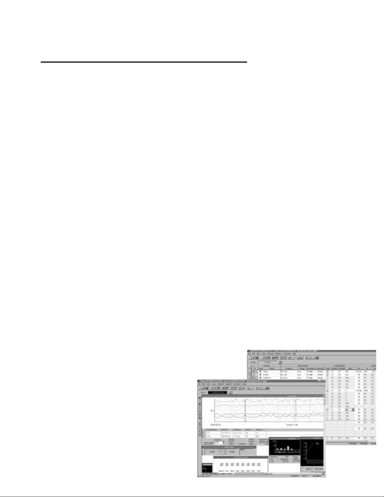
software. HP BenchLink Data
Logger software gives you a familiar
Microsoft Windows®interface for
test configuration and real-time
data display and analysis. Even
better, this full-featured data
logging application is included free
with every standard HP 34970A.
What can you expect
from a data acquisition system
that’s this affordable?
Just about
everything!
HP 34970A Data Acquisition/Switch Unit

More power and flexibility
than you ever imagined
you could afford
3-slot mainframe
offers up to 96 matrix crosspoints or
120 single-ended channels
3-year warranty to protect your investment
HP BenchLink Data Logger
software included;
drivers available for HP VEE and
National Instruments LabVIEW
®
Intuitive front panel: task-oriented,
self-guiding menus
50k readings of non-volatile
memory holds data when
power is removed
HI/LO alarm limits on each input
channel, plus 4 TTL alarm outputs
Scaling function for
converting raw inputs
into user-defined units
6
1
/2-digit (22-bit) internal
DMM measures 11 functions without
external signal conditioning
8 switch and control
plug-in modules to
choose from
Battery-backed real-time clockfor pacing
scans and timestamping readings
Built-in HP-IB and RS-232 interfaces
Monitor display
mode lets you
keep an eye on
tests in progress

Following are technical specifications for the HP 34970A Data
Acquisition/Switch Unit and its
modules. The explanations and
examples below are helpful in
understanding how to interpret
these specifications:
• Measurement accuracy is
specified as percent of reading
plus percent of range, where
reading is the actual measured
value and range is the name of
the scale (1V, 10V, etc)—not the
full scale value (1.2V, 12V,etc.).
• DMM measurement accuracies
include all switching errors.
Switching errors are also listed
separately in the module
specifications section.
Temperature measurement
accuracies include ITS-90
conversion errors. The
thermocouple accuracies include
the reference junction error as
well.
• Accuracies are listed as either
24-hour, 90-day or 1-year
specifications. This refers to the
length of time since the
instrument’s last calibration.
Use the specification that
matches your calibration cycle.
The 24-hour specifications are
useful for determining short-term
relative performance.
EXAMPLE 1: Basic dcV accuracy
Calculate the accuracy of the
following measurement:
9 V dc input
10 V dc range
1 year accuracy specifications
Normal operating temperature
(18ºC - 28ºC)
From the following page, the 1-year
accuracy is
0.0035% of reading + 0.0005%
of range
Which translates into
(0.0035/100 x 9 V)+
(0.0005/100 x 10 V) = 365µV
For a total accuracy of
365 µV / 9 V = 0.0041%
EXAMPLE 2: Extreme
operating temperature
When the HP 34970A is used
outside of its 18ºC-28ºC
temperature range, there are
additional temperature drift errors
to consider. Assume the same
conditions in example 1, but at a
35ºC operating temperature:
The basic accuracy is again
0.0035% of reading + 0.0005% of
range=365 µV.
Now, multiply the 10 V temperature
coefficient from the following page
by the number of degrees outside of
operating range for additional error:
(0.0005% reading + 0.0001%
range)/ºC x (35ºC - 28ºC) =
(0.0005% reading + 0.0001%
range)/ºC x 7ºC =
0.0035% reading + 0.0007% range
= 385 µV
Total error is then
365 µV + 385 µV = 750 µV or
0.008%
EXAMPLE 3: Thermocouple
measurement accuracy
Calculating the total thermocouple
reading error is easy with the
HP 34970A—just add the listed
measurement accuracy to the
accuracy of your transducer.
Switching, conversion, and
reference junction errors are
already included in the
measurement specification.
For this example, assume a J-type
thermocouple input reading 150ºC.
From the following page,
total error is
Thermocouple probe accuracy +
1.0 ºC
The probe vendor specifies
accuracy of 1.1ºC or 0.4 %,
whichever is greater
Total error is then
1.0ºC + 1.1 ºC = 2.1ºC total,
or 1.4 %
EXAMPLE 4: acV Accuracy
The acV function measures the true
RMS value of the input waveform,
regardless of waveshape. Listed
accuracies assume a sinewave
input. To adjust accuracies for nonsinusoids, use the listed crest factor
adder.
For this example, assume a ±1 V
square wave input with 50% duty
cycle and a 1 kHz frequency.
Accuracy for 1 V, 1 kHz sinusoid is
0.06% reading + 0.04% range
A 50% duty cycle squarewave has
a crest factor of
Peak Value / RMS value = 1 V / 1 V
= 1
From Crest Factor table, add
0.05% of reading
The total accuracy is
0.11% of reading + 0.04% of
range = 1.5 mV or 0.15 %
HP 34970A Technical Specifications

Accuracy Specifications
±(% of reading + % of range)
[1]
Includes measurement error, switching error, and transducer conversion error
Temperature
Function Range
[3]
Frequency, 24 Hour
[2]
90 Day 1 Year Coefficient
etc. 23°C±1°C 23°C±5°C 23°C±5°C 0°C-18°C
28°C-55°C
DC Voltage 100.0000 mV 0.0030 + 0.0035 0.0040 + 0.0040 0.0050 + 0.0040 0.0005 + 0.0005
1.000000 V 0.0020 + 0.0006 0.0030 + 0.0007 0.0040 + 0.0007 0.0005+ 0.0001
10.00000 V 0.0015+ 0.0004 0.0020 + 0.0005 0.0035 + 0.0005 0.0005 + 0.0001
100.0000 V 0.0020 + 0.0006 0.0035+ 0.0006 0.0045 + 0.0006 0.0005 + 0.0001
300.000 V 0.0020 + 0.0020 0.0035 + 0.0030 0.0045 + 0.0030 0.0005 + 0.0003
True RMS 100.0000 mV 3 Hz - 5 Hz 1.00 + 0.03 1.00 + 0.04 1.00 + 0.04 0.100 + 0.004
AC Voltage
[4]
to 100V 5 Hz - 10 Hz 0.35 + 0.03 0.35 + 0.04 0.35 + 0.04 0.035 + 0.004
10 Hz - 20 kHz 0.04 + 0.03 0.05 + 0.04 0.06 + 0.04 0.005 + 0.004
20 kHz - 50 kHz 0.10 + 0.05 0.11 + 0.05 0.12 + 0.05 0.011 + 0.005
50 kHz - 100 kHz 0.55 + 0.08 0.60 + 0.08 0.60 + 0.08 0.060 + 0.008
100 kHz - 300 kHz
[5]
4.00 + 0.50 4.00 + 0.50 4.00 + 0.50 0.20 + 0.02
300.0000V 3 Hz - 5 Hz 1.00 + 0.05 1.00 + 0.08 1.00 + 0.08 0.100 + 0.008
5 Hz - 10 Hz 0.35 + 0.05 0.35 + 0.08 0.35 + 0.08 0.035 + 0.008
10 Hz - 20 kHz 0.04 + 0.05 0.05 + 0.08 0.06 + 0.08 0.005 + 0.008
20 kHz - 50 kHz 0.10 + 0.10 0.11 + 0.12 0.12 + 0.12 0.011 + 0.012
50 kHz - 100 kHz 0.55 + 0.20 0.60 + 0.20 0.60 + 0.20 0.060 + 0.020
100 kHz - 300 kHz
[5]
4.00 + 1.25 4.00 + 1.25 4.00 + 1.25 0.20 + 0.05
Resistance
[6]
100.0000Ω 1 mA current source 0.0030 + 0.0035 0.008 + 0.004 0.010 + 0.004 0.0006 + 0.0005
1.000000 kΩ 1 mA 0.0020 + 0.0006 0.008 + 0.001 0.010 + 0.001 0.0006 + 0.0001
10.00000 kΩ 100 µA 0.0020 + 0.0005 0.008 + 0.001 0.010 + 0.001 0.0006 + 0.0001
100.0000 kΩ 10 µA 0.0020 + 0.0005 0.008 + 0.001 0.010 + 0.001 0.0006 + 0.0001
1.000000 MΩ 5.0 µA 0.002 + 0.001 0.008 + 0.001 0.010 + 0.001 0.0010 + 0.0002
10.00000 MΩ 500 nA 0.015 + 0.001 0.020 + 0.001 0.040 + 0.001 0.0030 + 0.0004
100.0000 MΩ 500 nA// 10 MΩ 0.300 + 0.010 0.800 + 0.010 0.800 + 0.010 0.1500 + 0.0002
Frequency 100 mV 3 Hz - 5 Hz 0.10 0.10 0.10 0.005
and Period
[7]
to 5 Hz - 10 Hz 0.05 0.05 0.05 0.005
300 V 10 Hz - 40 Hz 0.03 0.03 0.03 0.001
40 Hz - 300 kHz 0.006 0.01 0.01 0.001
DC Current 10.00000 mA <0.1 V burden 0.005 + 0.010 0.030 + 0.020 0.050 + 0.020 0.002+ 0.0020
(HP 34901A only) 100.0000 mA <0.6V 0.010 + 0.004 0.030 + 0.005 0.050 + 0.005 0.002 + 0.0005
1.000000 A <2 V 0.050 + 0.006 0.080 + 0.010 0.100 + 0.010 0.005 + 0.0010
True RMS AC 10.00000 mA 3 Hz - 5 Hz 1.00 + 0.04 1.00 + 0.04 1.00 + 0.04 0.100 + 0.006
Current and
[4]
5 Hz - 10 Hz 0.30 + 0.04 0.30 + 0.04 0.30 + 0.04 0.035 + 0.006
(HP 34901A only) 1.000000 A 10 Hz - 5 kHz 0.10 + 0.04 0.10 + 0.04 0.10 + 0.04 0.015 + 0.006
100.0000 mA
[8]
3 Hz - 5 Hz 1.00 + 0.5 1.00 + 0.5 1.00 + 0.5 0.100 + 0.06
5 Hz - 10 Hz 0.30 + 0.5 0.30 + 0.5 0.30 + 0.5 0.035 + 0.06
10 Hz - 5 kHz 0.10 + 0.5 0.10 + 0.5 0.10 + 0.5 0.015 + 0.06
Temperature Type Best Range Accuracy
[9]
Extended Range Accuracy
[9]
Thermocouple B 1100°C to 1820°C 1.2°C 400°C to 1100°C 1.8°C
E -150°C to 1000°C 1.0°C -260°C to -150°C 1.5°C
J -150°C to 1200°C 1.0°C -210°C to -150°C 1.2°C
K -100°C to 600°C 1.0°C -230°C to -100°C 1.5°C
0.03 °C
N -100°C to 1300°C 1.0°C -220°C to -100°C 1.5°C
R 300°C to 1760°C 1.2°C -50°C to 300°C 1.8°C
S 400°C to 1760°C 1.2°C -50°C to 400°C 1.8°C
T -100°C to 400°C 1.0°C -240°C to -100°C 1.5°C
RTD R0from 49 Ω -200°C to 600°C 0.06°C 0.003 °C
to 2.1 kΩ
Thermistor 2.2 k, 5k, 10k -80°C to 150°C 0.08°C 0.002 °C
[1] Specifications are for 1 hr warm-up and 61/2digits, Slow ac filter
[2] Relative to calibration standards
[3] 20% over range on all ranges except 300 Vdc and ac ranges and 1 Adc and ac current ranges
[4] For sinewave input > 5% of range. For inputs from 1% to 5% of range and < 50 kHz, add 0.1%
of range additional error
[5] Typically 30% of reading error at 1 MHz, limited to 1 x 10
8
V Hz
[6] Specifications are for 4- wire ohms function or 2-wire ohms using Scaling to remove
the offset. Without scaling, add 1 Ωadditional error in 2-wire Ohms function
[7] Input > 100 mV. For 10 mV inputs multipy % of reading error x 10
[8] Specified only for inputs >10 mA
[9] 1 year accuracy. For total measurement accuracy, add temperature probe error

Measurement Characteristics
DC Voltage
Measurement Method: Continuously Integrating Multi-slope III
A-D Converter
A-D Linearity: 0.0002% of reading + 0.0001 % of range
Input Resistance:
100 mV, 1 V, 10 V ranges Selectable 10 MΩ or > 10,000 MΩ
100V, 300V ranges 10 MΩ± 1%
Input Bias Current: < 30 pA at 25°C
Input Protection: 300 V all ranges
True RMS AC Voltage
Measurement Method: AC coupled True RMS — measures the
AC component of the input with up to
300 Vdc of bias on any range
Crest Factor: Maximum of 5:1 at Full Scale
Additional Crest Factor
Errors (non-sinewave): Crest Factor 1-2 0.05 % of reading
Crest Factor 2-3 0.15 % of reading
Crest Factor 3-4 0.30 % of reading
Crest Factor 4-5 0.40 % of reading
Input Impedance: 1 MΩ± 2% in parallel with 400 pF
Input Protection: 300 Vrms all ranges
Resistance
Measurement Method: Selectable 4-wire or 2-wire Ohms
Current source referenced to LO input
Offset Compensation: Selectable on 100Ω, 1kΩ, 10kΩranges
Maximum Lead Resistance: 10% of range per lead for 100 Ω and
1 kΩ ranges. 1 kΩ on all other ranges
Input Protection: 300 V on all ranges
Frequency and Period
Measurement Method: Reciprocal counting technique
Voltage Ranges: Same as AC Voltage function
Gate Time: 1s, 100 ms, or 10 ms
Measurement Timeout: Selectable 3Hz, 20Hz, 200Hz LF limit
DC Current
Shunt Resistance: 5 Ωfor 10 mA, 100 mA; 0.1 Ωfor 1 A
Input Protection: 1A 250V fuse on HP 34901A module
True RMS AC Current
Measurement Method: Direct coupled to the fuse and shunt.
AC coupled True RMS measurement
(measures the ac component only)
Shunt Resistance: 5 Ωfor 10 mA; 0.1 Ωfor 100 mA, 1 A
Input Protection: 1A 250V fuse on HP 34901A module
Thermocouple
Conversion: ITS-90 software compensation
Reference Junction Type: Internal, Fixed, or External
Open thermocouple Check: Selectable per channel. Open >5kΩ
Thermistor 44004, 44007, 44006 series
RTD α = 0.00385 (DIN) and α = 0.00392
Measurement Noise Rejection 60 (50) Hz
[1]
dc CMRR: 140 dB
ac CMRR: 70 dB
Integration Time Normal Mode Rejection
[2]
200 plc / 3.33s (4s) 110 dB
[3]
100 plc / 1.67s (2s) 105 dB
[3]
20 plc / 333 ms (400 ms) 100 dB
[3]
10 plc / 16.7 ms (20 ms) 95 dB
[3]
2 plc / 33.3 ms (40 ms) 90 dB
1 plc / 16.7 ms (20 ms) 60 dB
< 1 plc 0 dB
Operating Characteristics
[4]
Single Channel Measurement Rates
[5]
Function Resolution reading/s
dcV, 2-wire Resistance 6
1
/2digits (10 plc) 6 (5)
5
1
/2digits (1 plc) 57 (47)
4
1
/2digits (0.02 plc) 600
Thermocouple 0.1°C (1 plc) 57 (47)
(0.02 plc) 220
RTD, Thermistor 0.01°C (10 plc) 6 (5)
0.1°C (1 plc) 57 (47)
1°C (0.02 plc) 220
acV 6
1
/2Slow (3 Hz) 0.14
6
1
/2Med (20 Hz) 1
6
1
/2Fast (200 Hz) 8
6
1
/
2
[6]
100
Frequency, Period 6
1
/2digits (1s gate) 1
5
1
/2digits (100 ms) 9
4
1
/2digits (10 ms) 70
System Speeds
[7]
INTO Memory ch/s
single channel dcV 600
34902A scanning dcV 250
34907A scanning digital in 250
34902A scanning dcV with scaling & 1 alarm fail 220
34907A scanning totalize 170
34902A scanning temperature 160
34902A scanning acV
[6]
100
34902A scanning dcV/Ohms on alternate channels 90
34901A/34908A scanning dcV 60
INTO and OUT of memory to HP-IB or RS-232 (init, fetch)
34902A scanning dcV 180
34902A scanning dcV with timestamp 150
OUT of memory to HP-IB
Readings 800
Readings with timestamp 450
Readings with all format options ON 310
OUT of memory to RS-232
Readings 600
Readings with timestamp 320
Readings with all format options ON 230
DIRECT to HP-IB or RS-232
single channel dcV 440
34902A scanning dcV 200
single channel MEAS DCV 10 / MEAS DCV 1 25
single channel MEAS DCV/ MEAS OHMS 12
[1] For 1 KΩ unbalance in LO lead
[2] For power line frequency ±0.1%
[3] For power line frequency ±1% use 80 dB or ±3% use 60 dB
[4] Reading speeds for 60 Hz and (50 Hz) operation
[5] For fixed function and range, readings to memory, scaling and alarms off
[6] Maximum limit with default settling delays defeated
[7] Speeds are for 4
1
/2digits, delay Ø, display off, autozero off. Using 115 kbaud RS-232 setting

System Characteristics
Scanning Inputs
Analog HP 34901A, HP 34902A, and HP 34908A
multiplexer channels
Digital HP 34907A digital in and totalize
Scan list Scans channels in ascending order
Scan Triggering
Source Interval, external, button press, software,
or on monitor channel alarm
Scan count 1 to 50,000 or continuous
Scan interval 0 to 99 hours; 1ms step size
Channel delay 0 to 60 seconds per channel; 1 ms step size
External trig delay <2 ms. With monitor on <200 ms
External trig jitter <2 ms
Alarms
Analog inputs Hi, Lo, or Hi + Lo evaluated each scan
Digital inputs HP 34907A digital in: maskable pattern match
or state change
HP 34907A totalize: Hi limit only
Monitor channel Alarm evaluated each reading
Alarm Outputs 4 TTL compatible
Selectable TTL logic Hi or Lo on fail
Latency 5 ms (typical)
Memory Battery backed, 4 year typical life
[1]
Readings 50,000 with timestamp
Readable during scan
States 5 instrument states with user label
Alarm Queue Up to 20 events with channel number, reading,
and timestamp
System Features
Per-channel Math Individual Mx + B scaling and
Min/Max/Average calculated real time
Power Fail Recovery Resumes scanning automatically
Relay maintenance Counts each relay closure and stores on module
User resettable.
Real time clock Battery-backed, 4 year typical life
[1]
General Specifications
Power Supply 100V / 120V / 220V / 240V ±10%
Power Line Frequency 45 Hz to 66 Hz automatically sensed
Power Consumption 12 W (25 VA peak)
Operating Environment Full accuracy for 0°C to 55°C
Full accuracy to 80% R.H. at 40°C
Storage Environment -40°C to 70°C
[1]
Weight Net: 3.6 kg (8.0 lbs)
Safety Conforms to CSA, UL-1244, IEC 1010 Cat I
RFI and ESD CISPR 11, IEC 801/2/3/4
Warranty 3 years
Software
HP BenchLink Data Logger (not included with Option 001)
System Requirements
[2]
PC Hardware 486, 66 MHz, 16 MB RAM, 12 MB disk space
Operating System
Windows®3.1,Windows 95®, Windows NT 4.0
®
Computer Interfaces
[3]
HP-IB HP 82335B, 82340A/B/C, 82341A/B/C/D
National Instruments AT-GPIB/TNT, PCI-GPIB
LAN -to- HP-IB HP 2050A (Windows 95 and NT only)
RS-232 (Serial Port) PC COM 1-4
HP BenchLink Features
Configuration Spreadsheet-like setup page
Upload and Download intrument setups
Computed channels using
+ - * / , dB, dBm, dBV, x
2
, √x
and full, 1/2, or 1/4 bridge strain
Graphical Displays
Real-time and historical data displays
Add, delete, size, and configure real time
Strip chart with markers and alarm indication,
X-Y chart with curve fit, Histogram,
Bar meter, Digital meter, and Data table
Graphical Controls
Sliders, switches, buttons, and LED lights
Alarm / Limit testing
Start / Stop scanning on alarm condition
Control HP 34903A relay state or HP 34907A
digital output on alarm
Data
Real time streamed (saved) to disk
Copy data or graphics to windows clipboard
Export user-selected data to ASCII file, CSV, TSV
Event logging
Automatic entry of alarms and errors
Enter user notes real time
Printing
Setup spreadsheet, all graphics, and
event log entries
HP BenchLink Performance
[4]
Scan and save to disk 100 ch/s 2 strip charts displayed
Instrument Driver Support for Programming Languages
Universal Compatible with Windows 95 and NT
Instrument Driver HP VEE 3.2,
Visual Basic 4.0,
LabWindows CVI 4.0,
LabVIEW 4.0
LabVIEW Driver (VI) LabVIEW 4.0
[1] Storage at temperatures above 40°C will decrease battery life
[2] Software provided on CD-ROM and includes utility to create floppy disks for installation
[3] Interface and driver must be purchased and installed separately
[4] 90 MHz Pentium, 20 MB RAM
Windows, Windows 95, and Windows NT are registered trademarks of Microsoft Corp.
LabVIEW is a registered trademark of National Instruments Corporation.
_

Module Specifications
The HP 34970A accuracy
specifications already include the
switching offset and reference
junction errors shown below.
These errors are listed separately
for determining system error with
external measurement devices.
Up to three modules, in any
combination, can be inserted into a
single mainframe. The HP 34970A's
internal DMM connections are
accessible only through the HP
34901A, HP 34902A, and HP 34908A
low-frequency multiplexers.
On-module screw terminals accept
wire sizes from 16 gage to 22 gage.
20 gage wire is recommended for
high channel count applications.
The HP 34905A and HP 34906A RF
Multiplexers use SMB connectors.
A standard set of (10) BNC-to-SMB
adapter cables is provided with
each RF module for convenient
BNC connections.
Multiplexer Actuator Matrix RF Multiplexer Multifunction
GENERAL 34901A 34902A 34908A 34903A 34904A 34905A 34906A 34907A
Number of Channels 20 + 2 16 40 20 4 x 8 Dual 1 x 4 See
2/4 wire 2/4 wire 1 wire SPDT 2 wire 50 Ω 75 Ω Document #4906
Connects to Internal DMM • • • for module
Scanning Speed 60 ch/s 250 ch/s 60 ch/s specifications
Open/Close Speed 120/s 120/s 70/s 120/s 120/s 60/s
INPUT
Voltage (dc , ac rms) 300V 300V 300V 300V 300V 42V
Current (dc , ac rms) 1A 50mA 1A 1A 1A 0.7A
Power (W , VA) 50W 2W 50W 50W 50W 20W
DC CHARACTERISTICS
Offset Voltage
[1]
< 3uV < 6uV < 3uV < 3uV < 3uV < 6uV
Initial Closed Channel R
[1]
< 1 Ω < 1 Ω < 1 Ω < 0.2 Ω < 1 Ω < 0.5 Ω
Isolation ch-ch, ch-earth > 10 G Ω > 10 G Ω > 10 G Ω > 10 G Ω > 10 G Ω > 1 G Ω
AC CHARACTERISTICS
Bandwidth 10 MHz 10 MHz 10 MHz 10 MHz 10 MHz 2 GHz
[2]
2 GHz
[2]
Insertion Loss (dB) 10 MHz -0.1 -0.1
100 MHz -0.4 -0.4
500 MHz -0.6 -0.5
1 GHz -1 -1
1.5 GHz -1.2 -1.5
2 GHz -3 -2
SWR 10 MHz 1.02 1.02
100 MHz 1.05 1.05
500 MHz 1.20 1.25
1 GHz 1.20 1.40
1.5 GHz 1.30 1.40
2 GHz 1.40 2.00
ch-ch Cross Talk (dB)
[3]
10 MHz -45 -45 -18
[4]
-45 -33 -100 -85
100 MHz -85 -75
500 MHz -65 -65
1 GHz -55 -50
1.5 GHz -45 -40
2 GHz -35 -35
Risetime < 300 ps
Signal Delay < 3 ns
Capacitance HI - LO < 50 pF < 50 pF < 50 pF < 10 pF < 50 pF < 20 pF
LO - Earth < 80 pF < 80 pF < 80 pF < 80 pF < 80 pF —
Volt-Hertz limit 10
8
10
8
10
8
10
8
10
8
10
10
OTHER
T/C Cold Junction Accuracy
[1]
(typical)
0.8°C 0.8°C 0.8°C
Switch Life No Load (typical) 100M 100M 100M 100M 100M 5M 5M
Rated Load (typical)
[5]
100k 100k 100k 100k 100k 100k 100k
Temperature Operating all cards — 0°C to 55°C
Storage all cards — -20°C to 70°C
Humidity (non-condensing) all cards — 40°C / 80% RH
[1] Errors included in DMM measurement accuracy specifications
[2] Bandwidth direct to card SMB connectors
[3] 50Ω source, 50Ω load
[4] Isolation within channel 1 to 20 or 21 to 40 banks is -40 dB
[5] Applies to resistive loads only
HP 34970A Data Acquisition/Switch Unit
 Loading...