

Page 1

User’s Manual
3488 Mode Supplement
This manual describes the Agilent 3499A/B/C Switch/Control System
when used in the 3488 mode of ope rat ion. T hi s manual is a supplement
to the Agilent 3499A/B/C Switch/Control System User’s Manual (shipped
with the instr ument). Adobe Ac robat (PD F) vers ions of the user’s manual
are available at www.agilent.com.
©
Copyright Agilent Technologies, Inc. 1999-200 2
Agilent 349 9A/B/C
Switch/Control System
Page 2

Agilent 3499A/B/C at a Glance
The Agilent Technologies 3499A/B/C Switch/Control System provides a
convenient mechanical and programming environment for a v ariety of
plug-in modules. With appropriate plug-in modules, the Switch/Control
System pr ov id e s high density/high speed switching and digi tal I/O
capability.
Switch/Control System Features
•
Intuitive and easy-to-use user interface
•
GPIB (IEEE 488) or RS-232 interface control
•
External triggering capability
•
Built-in 4-bit digital I/O port
•
Store and recall up to 50 customized instrument setups
•
SCPI (Standard Commands for Programmable Instruments)
compatibilit y
•
Relay cycle count informa tion for preventive maintenance
•
Downloadable fir m war e upgrades
Agilent 3499A Features
•
Five plug -in slots
•
Full rack width
Agilent 3499B Features
•
Two plug -i n slots
•
Half rack width
Agilent 3499C Features
•
Nine plug-in slots
•
Full rack width
Note: Unless otherwise indicated, this manual applies to all Serial Numbers.
2
Page 3

Plug-in Mo du les at a Glance
The Agilent 3499A/B/C mainframes support a variety of plug-in modules
to make test sys te m configuration easy.
Multip lexer Modules
N2260A 40-Channel MUX Module (armature relays)
N2266A 40-Channel MUX Module (reed relays)
N2270A 10-Channel High Voltage MUX Module
44470A 10-Channel MUX Module
44470D 20-Channel MUX Module
General Purpose Relay Modules
N2261A 40-Channel GP Relay Module
N2267A 8-Channel High Current GP Module
44471A 10-Channel GP Relay Module
44471D 20-Channel GP Relay Module
44477A 7-Channel Form-C Relay Module
Matrix Modules
N2262A 4 x 8 Matrix Module
44473A 4 x 4 Matrix Module
High Frequency Switching Modules
N2268A 50Ω 3.5GHz Dual 4-to-1 MUX Module
N2272A 1 GHz RF 1-to-9 MUX Module
N2276A/B Dual 1-to-6 (4) Microwave MUX/Attenuator Module
44472A Dual 4-Channel VHF Switch Module
44478A/B 50Ω/75Ω 1.3 GHz Multiplexer
44476A 3-Channel 18 GHz Switch Module
44476B 2-Channel Microwave Switch Module
1
1
Optic al Switch Modules
N2280A Optical Switch Quad 1-to-2 MUX Module
N2281A Optical Switch Dual 1-to-4 MUX Module
N2282A Optical Switch 1-to-8 MUX Module
1
Digita l I/ O M odules
N2263A 32 -Bit Digital I/O Module
44474A 16-Bit Digital I/O Module
Multifunc tion/Special Purpose Modules
N2264A 12-Channel GP & 3-Channel High-current GP & 16-Bit Digital I/O
N2265A 4 x 4 Matrix & 16-Bit Digital I/O Module
44475A Breadboard Module
1
These modules are NOT supported in the 3488 Mode of operation.
3
Page 4

The Front Pane l at a G lance
1. Power On/Standby 8. Scan Keys (see page 78)
2. Reset Module/Instrument 9. Main Menu
3. Shift/Local 10. Open/Close Relay Channels
4. Store/Recall Instrument State 11. Enter a Value/Confirm Selection
5. Monitor Channel/Port/Module 12. Read/Write Digital I/O Ports
6. View Menu 13. Knob
7. Mode Menu 14. Navigation Arrow Keys
Note
The front panel shown above is the Agilent 3499B. The 3499A and 3499C
front panels are similar and have identical functionality.
4
Page 5

Annunciators
The Display at a Glance
Channel/Slot Number
The display is divided into several areas. The channel and slot number is
always displayed on the right corner of the display. The main area,
which is in the center of the display, is primarily used to display channel
status (open or closed), information messages, menu items, prompt information, error messages, and so on. Around the display are annunciators
to indicate var ious sta te s of the inst ru m ent o pe rati o n. The a n nunciators
are summarized below.
Annunciator Indication
SCAN Scan is initiated.
MON Instrument is in monitor mode.
VIEW Scan list, errors or relay cycle counts are being viewed.
CONFIG Any configuration key has been pressed.
* Instrument is advancing a scan step.
ADRS Instrument is active on the remote interface.
RMT Instrument is in remote mode.
ERROR Error queue is not empty.
EXT Scan is waiting for external trigger source.
SHIFT Shift key has been pressed.
Other annunciators in the display are not used in the Agilent 3499A/B/C
system.
5
Page 6

The Rear Panel at a Glance
The figure be low sh o ws the A gilent 3499A rear panel.
Slot 1
Slot 2
Slot 3
Slot 0
Control Modul e
The figure be low sh o ws the A gilent 3499B rear panel.
Slot 4
Slot 5
GPIB Connector RS-232 Connector
Mini DIN Connector
Power Input
Slot 1
Slot 2
Slot 0
Control Module
GPIB Connector RS-232 Connector
Power Input
Mini DIN Connector
6
Page 7

The figure be low sh o ws the A gilent 3499C rear panel.
Option FP1 (1 -s lot) and FP2 (2-slot) filler panels can be ordered to cover
any un used slo ts.
Slot 0
Control Module
Mini DIN Connector
Slot 7
(2 slot width)
Slot 6
Slot 8
Slot 9
(3 slot width)
(3 slot width)
Slot 5
Slot 3
Slot 4
Slot 1
Slot 2
GPIB Connector
RS-232 Connector
Power Input
WARNING For prot ection from electri cal shock, the power cord grou nd must not be
defeated.
The Mini DIN Connector
The rear panel mini DIN connector is used to make connections to
external triggers and the built-in digital I/O port. An Agilent N2289A
cable (mini DIN to D9) can be ordered to assist connections to external
devices. The figure below shows the pins used in the mini DIN connector.
7
Page 8

In This Book
Quick Start Chapter 1 prepares the switch/control sy stem for use and
helps you get familiar with a few of its front-panel features.
Front - Panel Menu Operation Chapter 2 introduces you to the frontpanel menu and describes some of the switch/control system’s menu
features.
System Overview Chapt er 3 gives an overview of a switch/control
system, describes how parts of the system work together, and describes
the channel addressing scheme used.
Feature s and Function s Chapter 4 gives a detailed description of the
swit c h/control system’s capabilities and operation. This chapter is useful
for operating the sw it ch/c on t r ol s y st e m from th e front panel or the remote
interface.
Remote Interface Reference Chapter 5 contains the 3488 mode
language reference used to program the switch/control system over a
remote inter fa ce.
Error Mess ag es Chapter 6 lists the error messages that may appear as
you are working with the instrument.
Application Programs
application programs to help you develop programs for your switch/
contr ol sy st e m.
Note This manual does not describe the plug-in modules except in a general
way. Use the Agilent 3499A/B/C User’s Manual (shipped with the
instrument) for complete details. A PDF version is also available at
www.agilent.com.
If you have questions relating to the oper ation of the Agilent 3499A/B/C,
call 1-800-452-4844 in the United States, or contact your nearest Agilent
Technologies Sales Office.
If your 3499A/B/C fails within one year of purchase, Agilent will either
repair or replace it free of charge. Call 1-877-447-7278 in the United
States (and ask for “Agilent Express”) or contact your local Agilent
Technologies Sales Office.
Chapter 7 contains several remote in te rf a ce
8
Page 9

Contents
Chapter 1 Quick Start 11
To Prepare the Instrument for Use 13
To Install a Module in the 3499A/B/C 15
Basic Operation 17
To Rack Mount the 3499A/B/C 21
Filler Panels 24
Chapter 2 Front-Panel Operation 25
To Power On the Instru ment 27
To Select the System Mode 27
To Monitor a Channel or a Slot 28
To Use a Digital I/O Port 30
To View Instrument Errors 35
Scanning Operation 37
To Pair Two Modules Together 40
To Configure fo r External Trig ge r 41
To Configur e th e Po we r- o n Sta te 4 3
To Configure th e Rem o te Interface 45
To Perform a Self-test 47
To Query the Firmware Revision 48
To Query the Serial Number 49
Local/Remote Control 50
Contents
Chapter 3 System Overview 51
Agilent 3499A/B/C Switch/Control System 53
Mainframes Overview 54
Firmware and Control Module Description 55
3488 Mode Differences 57
Plug-in Modules Overview 58
Channel and Slot Addressing 67
Factory Default and Reset States 71
9
Page 10

Contents
Chapter 4 Features and Functions 73
Monitoring a Channel or a Slot 75
Switching a Relay Channel 77
Scanning 78
Digi tal I/O Ope r ation 84
State Storage 94
Error Conditions 96
Self-Test 96
Display Control 97
Relay Cycle Counts 98
Chapter 5 Remote Interface Reference 99
Command Syntax 101
3488 Mode Command Q uick Reference 1 02
3488 Mode Commands 104
Chapter 6 Error Messages 135
Contents
Error Messages 136
Self T est Errors 136
Chapter 7 Application Programs 137
Visual C++ Example Program 139
Visual BASIC Example Program 141
BASIC Example Program 143
Index 145
10
Page 11

1
1
Quick Start
Page 12

Quick Start
1
This chapter describes the procedure to install the plug-in modules into
an Agilent 3499A/B/C mainframe and mount t he m ainfram e onto a
system rack. The basic operations of the Agilent 3499A/B/C Switch/
Control System is also described. The chapter contents include:
•
To Prepare the Instrument for Use, on page 13
•
To Install a Modu le in the 3499A/B/C, on page 15
•
Basic Operation, on page 17
•
To Rack Mount the 3499A/B/C, on page 21
12
Page 13

Chapter 1 Quick Start
To Prepare the Instrument for Use
To Prepare the Instrument for Use
1 Check the list of suppl ied ite ms
Verify that you have received the following items with your
Agilent 3499A/B/C mainframe:
1
❏ One power cord;
❏ This User’s Manual;
❏ One Quick Reference Guide;
❏ One Tie Down Clip 03499-21002 (for Agilent 3499B only);
❏ Any plug-in modules that you ordered are delivered in separate
shipping containers.
2 Connect the power cord and turn on the instrument
1. Connect the 3499A/B/C to an AC po we r sou rc e with the supplied
power cor d .
2. Push the Power sw itc h located on the low e r left si de of the front
panel.
3. On power-up, every segment in the display will light up briefly,
including all annunciators. Following this “starburst” display, the
internal self- test will begin.
4. If the self-test passe s
address are displayed, together with a “beep” sound. Then the display
shows the instrument model number and the active slot (slot 0).
1
, the default system mode and the GPIB
4
SCPI GPIB 9
3499 0
1
If the self-test failed, the failure will be displayed on the front panel. For
details of all self-test errors, refer to “Error Messages” starting on page
135.
13
Page 14

Chapter 1 Quick Start
To Prepare the Instrument for Use
1
When shipped from the factory, the SCPI mode and the GPIB interface
address of “9” are used. Slot 0 refers to the built-in controller board of the
switch/control system.
If the Instrument Does Not Turn On
1. Verify that the power cord is firmly plugged into the power receptacle
on the rear panel of the 3499A/B/C.
2. Make sure that the power source the 3499A/B/C is plugged into is
energized.
3. Verify that the 3499A/B/C is turned on.
Note If the 3499A/B/C DOES NOT turn on after you perform the above
procedure, contact your nearest Agilent Service Center (see page 8).
14
Page 15

Chapter 1 Quick Start
To Install a Module in the 3499A/B/C
To Install a Module in the 3499A/B/C
The plug-in modules you ordered were not installed in the mainframe.
The figur e on pag e 16 sho ws how to install a pl ug -in m o dule into the
3499B mainframe. Other mainframes use similar procedures.
1
WARNING Disconnect th e p o wer cor d from the rear panel of the ma inframe prior to
installing or removing an y modules.
Caution Use anti-static procedure s when c onfiguring, installing or removing any
plug-in modules. To prevent contamination to the modules that could
degrade performance, handle the modules by the side edges or shields
only. Do not touch the board surfaces or components.
Each plug-in module may have terminal block(s) and/or the cables for
wiring to external cir cui ts . These terminations are also shipped
separately.
For more details about terminal blocks, cables, and connections, see the
Agilent 3499A/B/C User’s Manual (shipped with the instrument) or visit
www.agilent.com.
4
Module Removal
To remove a plug-in module from the Agilent 3499A/B/C mainframe,
reverse the procedures shown on page 16.
15
Page 16

1
STEP 1
STEP 2
1. Face the mainframe rear panel toward you.
2. Select a slot in which the module is to be
installed.
STEP 3
1. Wire the screw terminal block (module
dependent).
2. Attach the screw terminal block to the plug-in
module.
(for modules with terminal blocks)
1. Hold the sides of the module, component side
down
2. Insert the module into the slot guides and slide
3. Push firmly until the module “snaps” into place.
4. Push both pla stic levers inward to lock the
STEP 4
1. Push firmly until the terminal block “snaps” into
2. Secure the screw terminal block with the two
, by the metal shields.
the module toward the front of the instrument.
module.
(for modules with terminal blocks)
place.
screws (Torque < 8 in-lbs).
Module installation
16
Page 17

Chapter 1 Quick Start
Basic Operation
Basic Operation
An Agilent 3499A/B/C Switch/Control System can be easily operated
from the front-panel, or programmed with SCPI commands over the
remote inter fa ce.
The following sections are only intended to show the basic front-panel
operation. F or deta iled front-panel op erat i on, refer to the “Front-Panel
Operation” chapter on page 25. For more information about
programming the instrument, refer to the “Remote Interface Reference”
chapter on page 99.
Channel Addressing
A channel refers to an individual relay on a switching module, or an
individual bit/port on a digital I/O module. The channel address is in the
form of snn, where s repres ents sl ot number and nn represents a channel
number.
4
1
For all mainframes, slot 0 refers to the 3499 controller board. Valid slot
numbers are:
3499A slots 0 through 5
3499B slots 0 through 2
3499C slots 0 through 9
The chan ne l nu m b e r, nn, is plug-in module dependent. For additional
information about channel numbers of individual plug-in modules, refer
to the table beginning on page 67.
17
Page 18

1
Chapter 1 Quick Start
Basic Operation
To Sele ct a Slot and Channel
When the instrument is first turned on, the display shows the model
number and the slot n umber of the controller board.
3499
Use the knob to selec t a channel on the acti ve slot. For example, with the
display shown above, turning the knob to the right will select the first of
the individual built-in digital I/ O ports.
DIN
The “DIN ” indic a te s the p o rt is set for a digital input operation. As the
knob is turned, the additional ports are displayed followed by any
installed plug-in modules.
If you have installed one or more plug-in modules, you can select the
module by pressing the right arrow key. F o r example, if an N2260A (40channel MUX module) is installed in slot 1, pressing the right arrow key
will show the module name and slot number.
0
090
N2260A 1
Turning the knob will then step through the individual channels on that
module.
MUX
OPEN
100
18
Page 19

Chapter 1 Quick Start
Basic Operation
To Open or Clo s e a C h annel
When a channel is selected, y ou can open or close the channel using the
front panel keys. For example, with an N2260A 40-channel MUX
installed in slot 1, select channel 00 as de scribed on t he previous page.
1
MUX
OPEN
100
4
Press the CLOSE key to close the channel.
MUX
Press the
OPEN
MUX
In this manner, you can select and control as many channels as you need.
The N2260A has 40 channels numbered 0 through 39 (in slot 1, 100
through 139). You may also select additional plug-in modules and
channels by turning the knob.
CLOSED
key to open the channel
OPEN
100
100
19
Page 20

1
Chapter 1 Quick Start
Basic Operation
To Open All Channels on a Module
You can open individual channels on a module one at a time as described
above. There are times, however, when it would be more expedient to
open all channels on a module at once.
Use the arrow keys to select the module to work with. You cannot have
an individual channel selected for this operation. For example, select the
module in slot 1 (using t he N2 260A as an example) to show a display
similar to this:
N2260A
Press and hold the card reset key. When you first press the k e y, the
display shows:
1
HOLD TO RESET
When the card has been reset, the display briefly shows:
RESET CARD
and then returns to:
N2260A
1
To Reset All Modules
You can reset all channels on all modules in the mainframe at once.
Press the shift key and th e n press and hold th e res et key. The display
shows:
HOLD TO RESET
When the mainframe has been reset, the display will briefly show the
reset and then return to the slot or channel display.
RESET . . .
20
Page 21

Chapter 1 Quick Start
To Rack Mount the 3499A/B/C
To Rack Mount the 3499A/B/C
You can mount the Agilent 3499A/B/C on a standard 19-inch EIA rack
cabinet with the opti on al rack -mo unting kits. The ins tru ct io ns and
mounting hardware are included with each rack-mounting kit.
1
Agilent 34 99A
To rack mount a 3499A, the full-rack-width mainframe, order either:
•
Rack-mount kit with hand les, part number 5183-7170, or
•
Rack-mount kit without handles, part number 5183-7171.
3499A
SWITCH/CONTROL SYSTEM
To Rack Mount an Agilent 3499A
4
21
Page 22

1
Flange
Filler Panel
Chapter 1 Quick Start
To Rack Mount the 3499A/B/C
Agilent 34 99B
To rack mount a single 3499B, order either:
•
Adapter kit, part number 5183-7172
(includes t he f lange and filler panel).
3499B
SWITCH/CONTROL SYSTEM
To Rack Mou nt a Single Agilent 3499B with Adapter kit 5183-7172
OR
•
A Support Shelf, part number 5063-9255,
•
A slide kit, part number 1494-0015,
•
And a filler panel, part number 5002-3999.
To Rack Mount a Single Agilent 3499B on a support shelf
22
Page 23

Chapter 1 Quick Start
To Rack Mount the 3499A/B/C
To rack mount two Agilent 3499B’s side-by-side (or any Syst em II
instrument next to an Agilent 3499B), order:
•
A Support Shelf, part number 5063-9255,
•
And a slide kit, part number 1494-0015.
1
4
To Rack Mou nt Two Agilent 3499B’s Side-by-side
23
Page 24

1
Chapter 1 Quick Start
Filler Panels
Agilent 34 99C
To rack mount an Agilent 3499C, order either:
•
Adapter kit without handles, part number 5063-9216, or
•
Adapter kit with handles, part number 5063-9223.
Adapter kit
To Rack Mount an Agilent 3499C
Filler Panels
Order filler panels to cover any unused slots in an Agilent 3499A/B/C.
•
1-slot filler panel, part number 03499-00023 (option FP1)
•
2-slot filler panel, part number 03499-00024 (option FP2)
24
Page 25

2
2
Front- Panel Operation
Page 26

2
Front-Panel Operation
The Agilent 3499A/B/C mainframes all operate the same from the frontpanel. This chapter does not give a detailed description of every possible
front-panel operation. It does, however, give you a good overview of the
front-panel menus and front-panel keys. See the “Features and
Functions” chapter on page 73 for additional discussions of the
instrument’s capabilities and operation. This chapter contents include:
•
To Power On the Instrument, on page 27
•
To Select the System Mode, on page 27
•
To Monitor a Channel or a Slot, on page 28
•
To Use a Digital I/O Port, on pag e 30
•
To View Instrument Errors, on page 35
•
Scanning Operation, on page 37
•
To Pair Two Modules Together, on page 40
•
To Configure for External Trigger, on page 41
•
To Configure the Power-on State, on page 43
•
To Configure the Remote Interface, on page 45
•
To Perform a Self-test, on page 47
•
To Que r y the Firmware Revision, on pa ge 48
•
To Query the Serial Number, on page 49
•
Local/Remote Control, on page 50
The following con ventions are used for the front-panel operation.
•
All keys on the front-panel keyboard are expressed in bold font and
normally associated with a “press”. For example, press Mon.
•
All the front panel display annunciators are expressed in bold font
followed by an “annunciator”. For example, MON annunciator.
•
The information shown on the fron t panel dis play is enclosed w ithin a
pair of quotation mark s.
26
Page 27

To Power On the Instrument
Chapter 2 Front-Panel Operation
To Power On the Instrument
To power on the ins trument, press the power switch on the front panel.
If the instrument is powered up for the first time, the instrument will
use the fact ory default settings as shown on page 71. Other w i se, the
instrument will power on to the state specified. Refer to "To Configure
the Power-on State", on page 43 for more details.
4
To Select the System Mode
The instrument can be operated in either SCPI mode or 3488A mode
(except Firmware REV 3.0, see page page 55 for mor e details). When
shipped from the factory, the instrument is set to the SCPI mode.
Perform the fol lowing procedure to select the desired system mode for
the instrument before any operation.
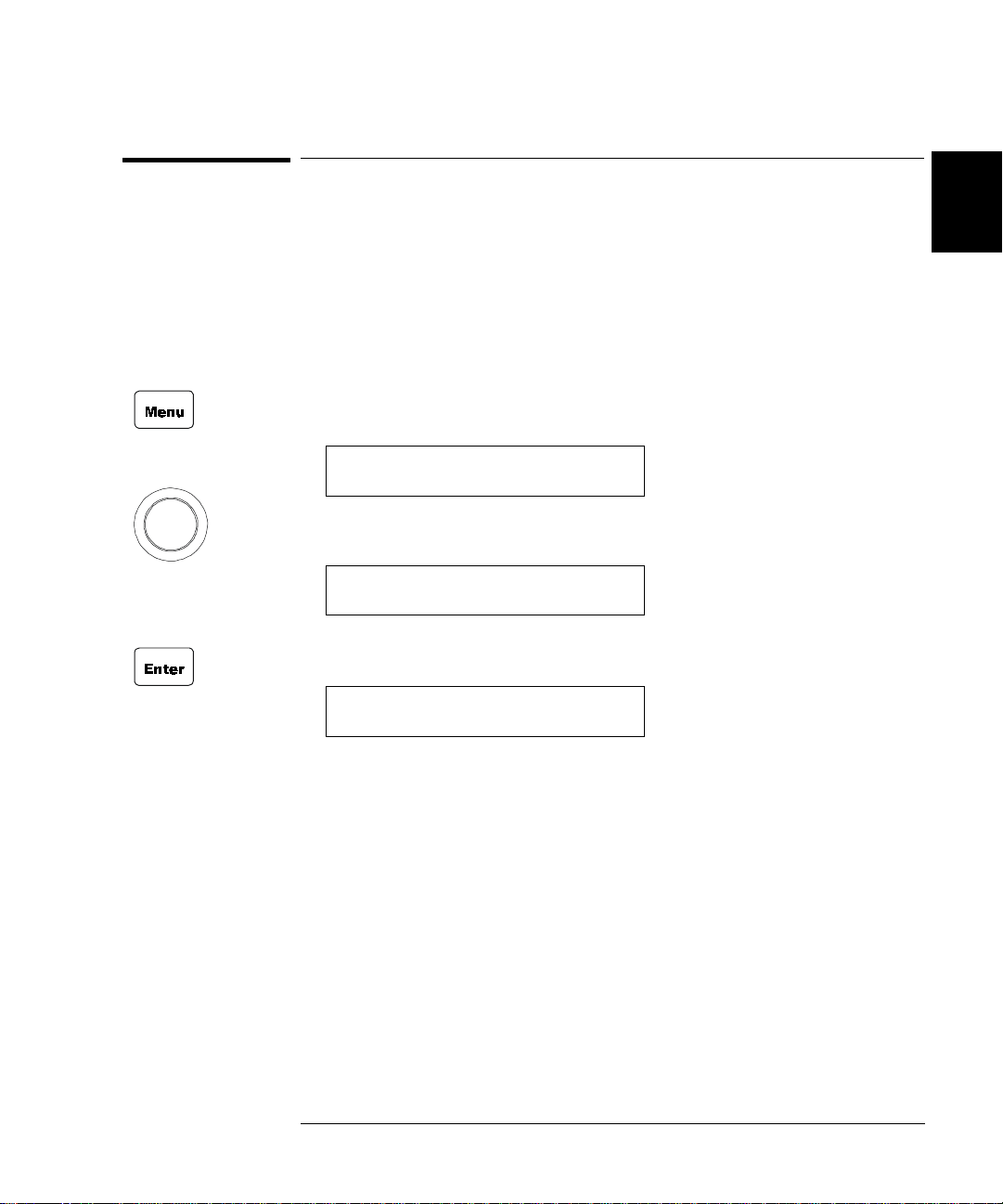
1. Press Menu, the CONFIG annunciator lights up. Turn the knob
until “SYSTEM MODE” is dis p layed, then press Enter.
SYSTEM MODE
2. Turn the knob until the desired system mode (i.e. 3488A MOD E ) is
displayed, then press Enter.
2
HP 3488A M OD E
3. The instrument will be reset if the system mode has been changed.
Otherwise, it retains the current mode and you can press Menu
again to exit this operation.
Note Switching between SCPI mode and 3488A mode will reset the
instrument to the factory default settings, except the GPIB address
which will retain its last setting.
This manual describes programming in the 3488 mode. For information
about the SCPI programming mode please refer to the User’s Manual
shipped with the Agilent 3499A/B/C, or visit www.agilent.com.
27
Page 28

Chapter 2 Front-Panel Operation
To Monitor a Chan nel or a Slot
2
To Monitor a Channel or a Slot
You can continuously monitor the current status of a particular
switching channel, a digital I/O port, or an entire plug-in module.
Monitoring from the front pane l is espec ially u seful when devel oping and
debugging remote interface commands.
1. Press the monitor key, the MON annunciator lights up to indicate the
instrument is in the monitoring state.
2. Select the slot or the channel/port to be monitored. The displayed
information depends on the selected module type. Typical displays
are shown in the table on page 76.
3. If only pa r t of the channel status on the module can be displayed at
one t i me, press Enter to display the next part.
For multiplexer modules and GP Relay modules, 10 channels can be
displayed at one time; for matrix modules, one Row or one Column
can be displayed at o ne time; for digital I/O modules, two 8-bit ports
can be displayed at one time. For multifunction modules, the first
function on the module is displayed, t hen the next.
4. Press the monitor key again to end monitoring (the MON
annunciator turns off).
Note The built-in digital I/O bits/port (on the controller module) can be
monitored either individually as bit channels (numbered 091 through
094) or as a 4-bit port (numbe red 090). However, the individual bit
channels on a digital I/O or multifunction module (with a DIO function)
cannot be monitored.
28
Page 29

Chapter 2 Front-Panel Operation
To Monitor a Channel or a Slot
.
Display Description
The display for a multiplexer or a GP relay module. This
1:0,,,,,,6,,,9, 2
display indic at es t hat the m o nitored module is in Slot 2 and
channels 10, 16, and 19 are closed.
The display for a matrix module. The top is the row
ROW 3:,1,,3,,,6,7 3
information, indicating that the relays on Row 3, Columns 1, 3,
6 and 7 of the module (in Slot 3) are closed. The lower display
is the column information, indicating that relays on column 3,
0;,,3,COL 3, 3
row 0 and 3 are closed.
The display for a digital I/O module. The first 2 digits on the left
00:H255 L254. 4
(“00” in this case) represents the “L” 8-bit port address. Adding
one to this value, the “H” 8-bit port address is obtained. Data
with a trailing decimal point indicates that the last operation on
that port was a WRITE, data without a trailing decimal point
indicates that the last operation on that port was a READ. This
display sh ows that th e data last read from Port 401 is 255 and
the data last written to Port 400 is 254.
The top display is for the built-in digital I/O Port 090 (control
DIO 12 090
module) and the data from the last operation.
The lower display indicates that data last written to the bit
channel 091 is 0.
DOUT 0 091
2
4
ROW 0:,1,,3, 5
00:H255 L254. 5
For a multifunction module, the first fu nction on the module is
displayed , then the next. This display is an example of a
multifunction module with matrix and DIO functions (in slot 5).
29
Page 30

Chapter 2 Front-Panel Operation
t
To Use a Digital I/O Port
To Use a Digital I/O Port
2
You can work with a digital I/O module as a port (all eight bits) or as
individual bits.
Readi ng a Digital I/O Po r t
You can read data from the built-in 4-bit digital I/O port, or any one of
the 8-bit ports on a digital I/O or multifunction module (with a DIO
function). You can read the entire p ort (all bit s) w h en you select the slot
(for example, the built-in port is channel 090). Alternately, you can read
an individual bit by selecting the channel (for example the first bit in the
built-in port is channel 091).
Perform the fol lowing procedure to read from a port:
1. Select a digital I/O por t. Use the kno b to se le ct the slot and channel
number. The channel number is in the form of snn, wher e s is the slot
number and nn is the channel number.
2. Read the data read from the selected port. For example, the display
below shows the data read from port 401.
DIN 401
DIN 401
255
11111111
Decimal forma
(default)
Binary format
The data display format of individual 8-bit ports can be specified
either in binar y or deci mal formats (as described on page 33). Once
specified, the format applies to all input and o utput operations on the
same port.
30
Page 31

Chapter 2 Front-Panel Operation
To Use a Digital I/O Port
Writing to a Digital I/O Port
You can write data to the built-in digital I/O port (num be red 090) or to
one of the built-in digital I/O port bits (numbered 091 through 094), or
any one of the 8-bit ports on a digital I/O or multifunc tion modul e (with a
DIO function). To write to a port:
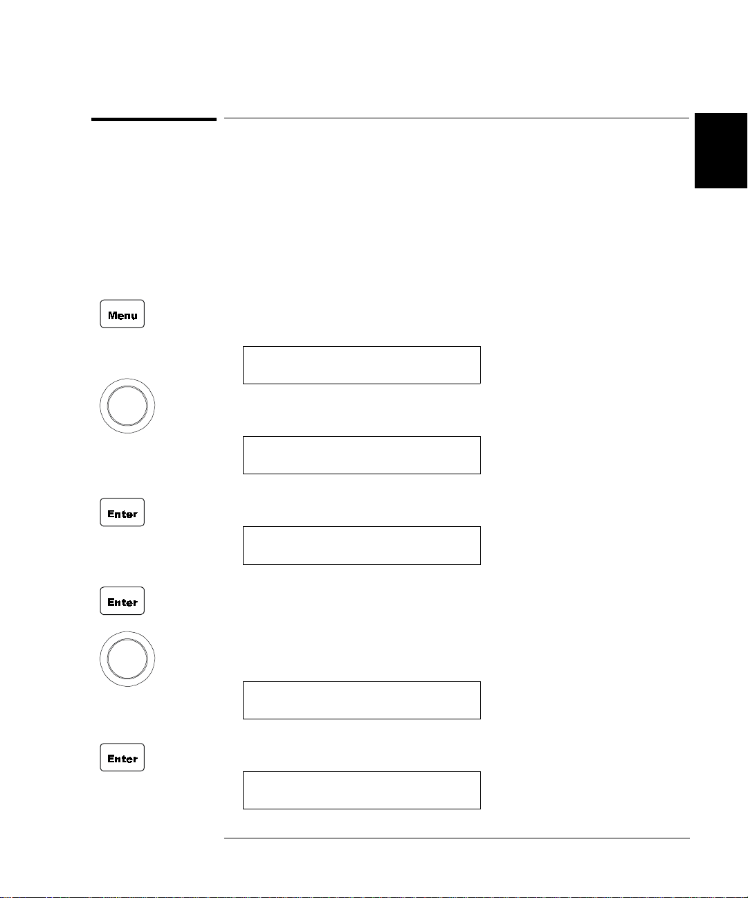
1. Select a digital I/O por t. Use the kno b to se le ct the slot and channel
number. The channel number is in the form of snn, wher e s is the slot
number and nn is the channel number. In the display, “DIN”
indicates that the last operation on the port was a READ, and
“DOUT”, a WRITE.
4
2
DIN
2. Press the Write key. “DOUT” is displayed to indicate the port is now
an output port. The current port value is displaye d.
401
DOUT 401255
3. Edit the value. Use the arrow keys to select the to-be-edited bit (the
digit to be edited is set to half bright in the display).
Turn the knob to modify the value. Use the arr ow keys to select the
next digit and the knob to modify its value.
DOUT
4. When the value is the one desired, press Enter to output the data to
the selected port.
5. Press Write again to cancel the current write operation.
254
401
Note Data display format of individual 8-bit ports can be specified either in
binary or decimal values (refer to the procedure on page 33). Once
specified, the format applies to all input and output operations on the
same port.
31
Page 32

2
Chapter 2 Front-Panel Operation
To Use a Digital I/O Port
To Configure a D ig ital I/O Mod ul e
Digital I/O modules can be configured for handshake modes and control
line, flag line, and I/O line polarity. U se the Mode menu to configure
digital I/O parameters. See “Digital I/O Operation” on page 84 for
detailed descriptions of the operating modes. Only plug-in modules can
be configu red this way, the b uilt-in digital I/O port (control mod ule) can
only be configured at the port level (see page 33).
The following proc edure configures a plug-in digital I/O module to use a
two line digital h and shake mode (m o d e 5) f or data t rans f e rs.
1. Select the slot in which a digital I/O or multifunction module is
installed. Th e channel number is in the form of snn, where s is the
slot number and nn is the channel number.
N2263A
2. Press the Mode key. The CONFIG annunciator lights up in the
display and the first-level menu is shown .
CONFIG DIO
3. Press Enter to begin the configuration. The display shows the
second-level menu choice.
4
4
MODE 1 4
4. Turn the knob until the d es ired flow co ntr o l mo d e (i.e., M ODE 5) is
displayed. The displ a y ed mode is half-bright.
MODE 5
4
32
Page 33

Chapter 2 Front-Panel Operation
To Use a Digital I/O Port
5. Press Enter to select the new mode. The display changes to show the
next menu level.
CONT POL POS
6. You may change other configurati on paramete r s as desired using the
same p r oc e d ure. When all desire d co nf igurations have b e en ma de ,
press the Mode key to exit the configuration men u. The CONFIG
annunciator turns off.
4
4
To Configure a D I O Port
You can configure an individual digital I/O port to change the data
polarity and the display format. The following procedure changes the
built-in digital I/O port to display in binary number format.
1. Select a digital I /O port (i.e., port 090). The channel number is in the
form of snn, where s is the slot n umber and nn is the channel number.
DIN 090
2. Press the Mode key. The CONFIG annunciator lights up in the
display. The first level menu is shown:
DATA POLARITY
090
2
3. Turn the knob to select the second menu level
DISP FORMAT
4. Press Enter to select the format parameter.
DECIMAL
090
090
33
Page 34
Chapter 2 Front-Panel Operation
To Use a Digital I/O Port
5. Turn the knob until the desired data display format (i.e., BINARY) is
displayed.
2
6. Press Enter to make the change and return to the first level of the
BINARY
Mode me nu.
DISP FORMAT
7. Press Mode again to exit the current configuration, the CONFIG
annunciator turns off.
Note Once you have selected the data display format for a port, it applies to
both input and output operations on that port.
090
401
34
Page 35
To View Instrument Errors
Chapter 2 Front-Panel Operation
T o View Instrument Errors
You can view errors from the fron t panel. This feature is especially
useful when developing remote instrument control. If an error occurs,
the ERROR annunciator in the display will light. Errors are stored in
the error queue in the order they occur. You read the erro rs in the same
order. After all errors have been read, the queue is empty and the
ERROR annunciator turns off. To view instrument errors:
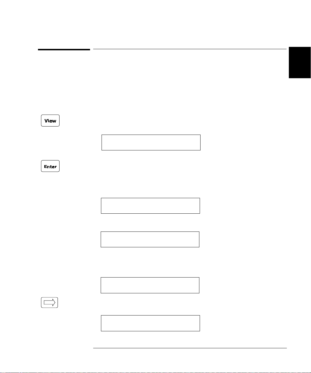
1. Press the View key. The VIEW annunciator lights up and the display
shows the first menu level.
ERROR
2. Press Enter to view the first error.
a. If no error is in the error queue (the ERROR annunciator is off),
the display shows “NO ERROR” and t hen automatic ally retur ns to
the first level of the View menu.
0
0
NO ERROR
4
2
ERROR
b. If there are errors (the ERRO R annunciator is on), the first error
in the error queue is displayed.
01:ERR -109
Press the right arrow key to scroll the display to show the entire
error m essage.
MISSING PARAMETER
0
35
Page 36

Chapter 2 Front-Panel Operation
To View Instrument Errors
3. Turn the knob to view other err o rs in the error queue (if any).
2
4. Press Enter to return to the first level of the View menu, the
ERROR annunciator turns off.
5. Press View again to exit the View menu operation, the VIEW
annunciator turns off.
Note All errors are cleared, and the ERROR annunciator turns off, once the
error queue is viewed. S ee the “Er ror Messages” chapter on page 135 for
a complete list of error messages.
36
Page 37
Scanning Operation
Chapter 2 Front-Panel Operation
Scanning Operation
The instrument allows you to combine an external measurement device
such as a Digital Multimeter (DMM) with multiplexer channels to create
a scan. During a scan, the instrument closes the confi gured multiplexer
channels one at a time to allow a measurement to be m ade on that
channel.
Before initiating a scan, a scan list must be set up. You can also specify
an arm source, a trigger sourc e, and the number of sweeps (a sweep is
one pass through the scan list) to control the scan process. All these can
be done from the S.List menu. The procedure in this chapter des cribes a
simple sca n from the front panel. For more inform a tio n abo ut scanning
and using the par am e te rs to contro l a scan , see pag e 78.
4
To Create a Scan List
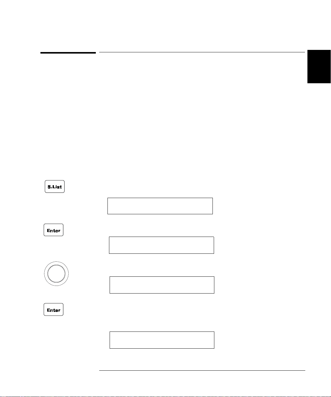
1. Press the S.List key to enter the scan list menu . The CONFIG
annunciator lights up and the first level of the menu is displayed.
ADD TO SCAN
2. Press Enter to begin the chann el selec tio n.
101
SELECT 101
2
3. Turn the knob to sel ect the firs t channel for the list (e.g., 103).
SELECT
4. Press Enter to add the chann el into the scan list. The star burst
character lights in the display to indicate the channel is now a part of
the scan li st.
SELECT *
103
103
37
Page 38
2
Chapter 2 Front-Panel Operation
Scanning Operation
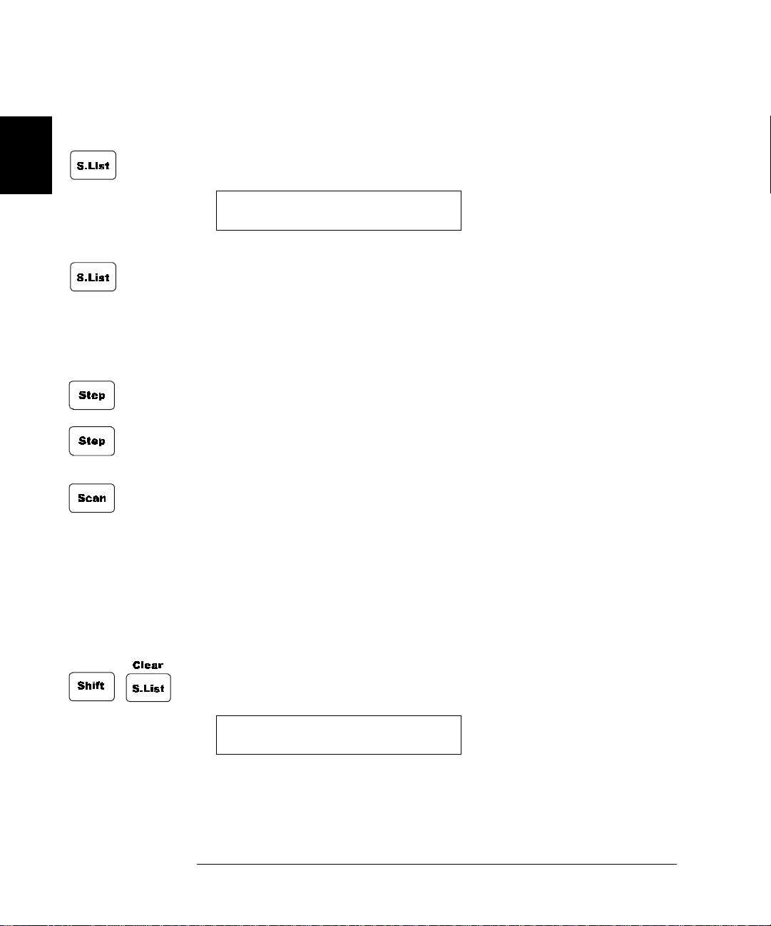
5. Repeat step 3 and 4 to add additional channels to the list.
6. When the desired channels have been added, press the S.List key
again to return to the first level of the menu.
ADD TO SCAN
7. Press S.List again to exit the menu. The CONFIG a n nunc i ato r tur ns
off.
107
To Perform Scanning
After the scan configuration is complete, the actual scan can be
performed.
1. Press the Step key to close the first channel in the scan list.
2. Press the Step key again to o pen the f i rst c h annel a nd close the next
channel in the list.
This procedu re shows a simple way to scan, one channel at a time for
each press of a front pane l key. You can als o pres s the Scan key to scan
all channels in the list according to the various scan parameters set. In
the default parameter state, pressing the Scan key will cause all the
channels in the list to cycle through at the maximum possible speed.
While this occu rs, the SCAN annunciator is lighted. For details about
the scan parameters, see page 78.
To Clear a Scan List
You can clear a scan list once it has been configured.
1. Press the Shift key and then the S.List key. The display will briefly
show:
101
CLR SCAN LIST
and then return to norm al oper atio n.
38
Page 39

Chapter 2 Front-Panel Operation
Scanning Operation
To View a Scan List
You can view which channels are included in a scan list. This example
assumes that channels 103 through 107 are included in the scan list.
1. Press the View key. The VIEW annunciator lights up and the display
shows the first level menu.
ERROR
2. Turn the knob until “SCAN LIST” is displayed.
3. Press Enter. The first channel in the scan list is displayed on the
channel area.
101
101
SCAN LIST
4
2
103
001 OF 005
Turn the knob to view other channels in the scan list.
104
002 OF 005
4. Press Enter to return to the f i rst level of the V iew menu.
SCAN LIST
5. Press View again to exit the View menu. The VIEW annunciator
turns off.
107
39
Page 40

Chapter 2 Front-Panel Operation
To Pair Two Modules Together
To Pair Two Modules Together
2
You can pair two modules together so that they operate as a single unit.
The two m od ules to be paired must be identic a l (that is, they must have
the same model number) and be installed in the same mainframe. When
two modules are paired together, any operation on a channel of one
module will be d uplicated on the correspo nd ing channel of the other
module. The exam ple below pairs modules installed in slots 2 and 5.
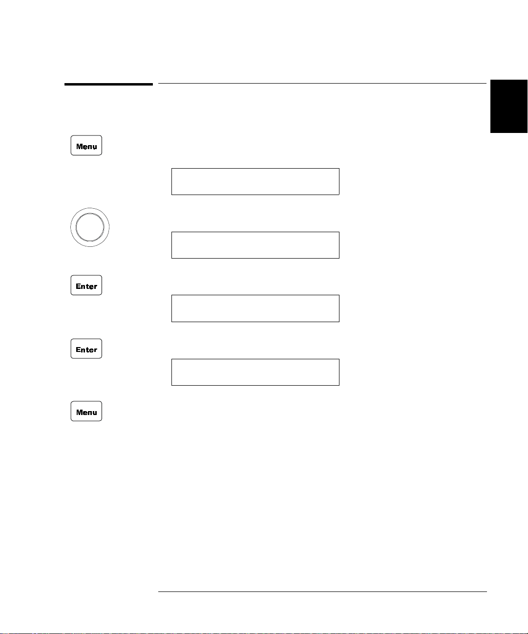
1. Press the Menu key. The CONFIG annunciator lights up and
“CARD PAIR” is displayed.
2. Press Enter.
When “FIRS T SLOT x” is displayed, turn the knob to selec t t he first
slot to be paired (i.e., Slot 2).
FIRST SLOT 2
3. Press Enter.
When “SECOND SLOT x” is displayed, turn the knob to select the
second slot to be paired (i.e., Slot 5) .
SECOND SLOT 5
4. Press Enter to return to the first level of the Me nu menu.
CARD PAIR
5. Press Menu again to exit the Menu menu. The CONFIG annunciator
turns off.
40
Page 41
Chapter 2 Front-Panel Operation
T o Configure for External Trigger
To Configure for External Trigger
You can use one of two modul e s for an external trigge r . The built-in rear
panel TRIG IN and TRIG OUT pair (on the control module) or the EI
(External Increment) and the CC (Channel Closed) pair on a 44474A
module. Only one pair can be used at a time. You can specify which pair
to use and whether a trigger out pulse is sent out when a relay is closed
during scanning operations. Refer to “Scanning” on page 78 for more
details.
1. Press the Menu key. The CONFIG annunciator lights up and the
display shows the first level menu.
CARD PAIR
2. Turn the knob to s how th e sec on d m e nu item, “CONF EXT TRIG”.
CONF EXT TRIG
3. Press Enter. The display shows the next level menu.
TRIG SLOT 0
4
2
41
Page 42

2
Chapter 2 Front-Panel Operation
T o Configure for External Trigger
4. Turn the knob t o sele ct the s lot f or the ex ternal tr igger . Slot 0 (cont rol
module) is the bui lt- in external trigger (available at t he rear panel
mini D IN c o nn e c t or , se e pa g e 7 ). I f a 44474A i s no t i n s ta l l e d, o nl y slot
0 will be shown. Press Enter. The display shows the current setting
for the external tri gger.
DISABLE
5. Turn the knob to show th e alter nat e cho ice.
ENABLE
6. Press Enter to accept the choice and return to the fi rst level menu.
CONF EXT TRIG
7. Press the Menu key to exit the menu. The CONFI G annunciator
turns off.
42
Page 43
Chapter 2 Front-Panel Operation
To Configure the Power-on State
To Configure the Power-on State
Firmware Rev 4.0 ONLY. To read your firmware ve rsion, see the
procedure on page 48. For more information about firmware revisions,
see “Firmware and Control Module Description” on page 55.
An instrument with Firmware REV 4.0 or later c an be set to power on to
the reset state (see “Factory Default and Reset States” on page 71) or to a
state previously stor ed in a specified memory location. The instrument
will return to the specified state the next time it is turned on.
1. Press the Menu key. The CONFIG annunciator lights up and the
display shows the first menu level.
4
CARD PAIR
2. Turn the knob until “POWER ON SET” is displayed.
POWER ON SET
3. Press Enter to show th e sec on d le v e l me nu.
PWR ON RESET
2
4. To set the instrument power-on to the reset state, press Enter. The
instrument will return to the first level menu.
Alternately, to set the instrument power-on to a stored stat e : Turn
the knob until “USER SET UP” is displayed.
USER SET UP
5. Press Enter to select the stored state to use.
POWER ON 05
43
Page 44

Chapter 2 Front-Panel Operation
To Configure the Power-on State
6. Turn th e knob to select the desired memory location (i.e. , 08).
POWER ON 08
2
7. Press Enter to accept the stored state and return to the first level
menu. More information about storing states is given on page 94 of
this manual.
POWER ON SET
8. Press the Menu key again to exit the Menu menu. The CONFIG
annunciator turns off.
Note If the instrument is set to power on to a previo usl y stored setup that is
no longer valid, it will automatically power on to the reset state and
“RECALL FAILED” will be displayed.
44
Page 45

Chapter 2 Front-Panel Operation
To Configure the Remote Interface
To Configure the Remote Interface
In 3488 mode, the instrument can communicate with a computer over
the GPIB interface. When shipped from the factory, the GPIB interface is
selected and its address is set to “9”.
Note The RS-232 interface can be configured and used only in SCPI mode.
GPIB Int e r face
Each device on the GPIB interface must have a unique address.
•
When shipped from the factory, the GP IB interfa ce is selected and its
address is set to “9”. The GPIB address of the instrument can be set to
any value between 0 and 30.
•
The GPIB address is stored in non-volatile memory, and does not
change when the instrument is turned off or reset.
•
Switching between SCPI mode and 3488A m o de c auses the
3499A/B/C to select the GPIB interface and its address setting.
To set the GPIB interface:
1. Press the Menu key. The CONFIG annunciator lights up and the
first level menu is shown.
CARD PAIR
2
4
2. Turn the knob to select “INTERFACE” in the menu.
INTERFACE
3. Press Enter to show the second level menu The active interface is
shown. If necessary, turn the knob until “GPIB/488” is displayed.
GPIB/488
45
Page 46

Chapter 2 Front-Panel Operation
To Configure the Remote Interface
4. Press Enter to select the interface and show the first parameter.
2
ADDRESS 09
5. Turn the knob to set GPIB address (i.e., 07). Va l i d addres se s range
from 00 to 30.
ADDRESS 07
6. Press Enter to show the second parameter.
SRQ ON
7. Press Enter to enabl e the in str um e nt to assert the SRQ lin e w h en
powered up. If the computer is so configured, this can be used to
interrupt the system computer.
To disable this feature, turn the knob to select “SRQ OFF ” and press
Enter. The instrum e nt returns to the first level of the men u.
8. Press Menu again to exit the menu.The CONFIG annunciator turns
off.
46
Page 47

To Perform a Self-test
Chapter 2 Front-Panel Operation
To Perform a Self-test
The self-test feature of the instrument provides you with a method of
verifyin g proper instrument operation.
1. Press the Menu key. The CONFIG annunciator lights up and the
first level menu is shown.
CARD PAIR
2. Turn the knob to select “SELFTEST”.
SELFTEST
3. Press Enter. The self test will begin. The display will briefly show a
“starburst” pattern (all display segments lit). Following the pattern,
the disp lay indicates:
TEST. . .
while the internal tests are being performed. The self-test takes
several seconds to complete.
If the self-test is successful, “PASSED” will be displayed. Otherwise,
the reason of the failure will be displayed. For details on self-test
failures,
occur during a self-test (in 3488A m ode).” on page 136.
refer to “ T h e e r ro rs liste d b e low indicate fa ilu re s that ma y
2
4
PASSED
4. Press Enter to return to the first level of the m e nu.
SELFTEST
5. Press Menu again to exit the Menu menu, the CONFIG annunciator
turns off.
47
Page 48

Chapter 2 Front-Panel Operation
To Query the Firmware Revision
To Query the Firmware Revision
2
Perform the following procedur e to quer y the 3499A/B/ C fir m war e an d
revision. For a description of the firmware and hardware revisions, see
“Firmware and Control Module Description” on page 55.
1. Press the Menu key. The CONFIG annunciator lights up and the
first level menu is shown.
CARD PAIR
2. Turn the knob to select “REVISION INFO”.
REVISION INFO
3. Press Enter. The system firmware revisio n nu mber will be displayed.
REVISION 4.0 2.0
4. Press Enter to return to the first level of the Me nu menu.
REVISION INFO
5. Press Menu again to exit the Menu menu, the CONFIG annunciator
turns off.
48
Page 49
To Query the Serial Number
Chapter 2 Front-Panel Operation
To Query the Serial Number
Perform the following proced ur e to que r y the 3499A/B/ C serial number.
1. Press the Menu key. The CONFIG annunciator lights up and the
first level menu is shown.
CARD PAIR
1. Turn the knob to select “SERIAL NO”.
SERIAL NO
2. Press Enter. The Agilent 3499A/B/C serial number is displayed.
MY12345678
3. Press Enter again to return to the first level of the Menu menu.
SERIAL NO
2
4
4. Press Menu again to exit the Menu menu, the CONFIG annunciator
turns off.
49
Page 50

Chapter 2 Front-Panel Operation
Local/Remote Contro l
Local/Remote Control
2
Note If the front panel keys are locked thro ugh either the SYSTem:RWLock
The instrument operates in two data entry modes, local and remote. In
local mode, all keys on the front panel are fully functional. In remote
mode, some front panel keys are locked (exception are: Local, Mo n,
View, Enter, the arrow keys, and the knob).
The instrument will en ter the re mote state upo n receipt of any command
over the remote interface. The RMT annunciator lights.
You can regain control of the front panel keys when the instrument is in
remote by pressing the Shift (Local) key. The RMT annunciator turns
off and the instrument ret urn to local mode.
command on the RS-232 interface or a LOCAL LOCKOUT command on
the GPIB interface, the local key will not function. You can restore the
front panel operation by cycling power the instrument or by sending a
SYSTem:LOCal command on the RS-232 interface, or a LOCAL command
on the GPIB interface.
50
Page 51

3
3
System Overview
Page 52

3
System Overview
An Agilent 3499A/B/C Switch/Control System is composed of a
mainframe and a set of Plug-in modules. This chapter provides a typical
configuration of a test system using the 3499A/B/C for switching and
control, followe d by a descr iptio n of the three mainfram e s a nd all the
Plug-in modules. The following sections are included in this chapter:
•
Agilent 3499A/B/C Switch/Co ntrol System, on page 53
•
Mainframes Overview, on page 54
•
Firmware and Control Module Description, on page 55
•
3488 Mode Differences, on page 57
•
Plug-in Modules Overview, on page 58
•
Channel and Slot Addressing, on page 67
•
Factory Default and Reset States, on page 71
52
Page 53

Chapter 3 System Overview
Agilent 3499A/B/C Switch/Contro l System
Agilent 3499A/B/C Switch/Con t rol System
The Agilent 3499A/B/C Switch/Control System provides high density and
high speed switching for routing test signals to and from your DUTs
(devices under test) and test instruments such as external DMMs,
scopes, counters, power supplies, etc. Whether you are involved in a
large production test system or a small R&D bench top system, the
Agilent 3499A/B/C provides an ideal combination of price/performance
solution. W ith a wide variety of availab le plu g-in mo d ules, you can
configure your test system much more e asi ly and flex ibly. The figure
below shows the typical configuration of a test system.
DUT
4
3
Agilent 3499A/B/C
IEEE488.2 (GPIB)
A Typical Test System
Source(s)
Plug-in
Modules
Instrument
Device(s)
Custom
Equipment
53
Page 54

Chapter 3 System Overview
Mainframes Overview
Mainframes Overview
Three mainframes are available:
Slots Available Rack Width
3499A
5 full width
3
3499B
3499C
1
The 3499C is d es ig ne d t o ac c om m od at e m u lti ple width plu g- i n mo du les and has 9 log ic al
slots but 14 mechanical slots. Slots 1 through 6 are 1-slot wide, slot 7 is 2-slots wide, and
slots 8 and 9 are each 3-slots wide. See the figure on page 7 for more information.
All mainframes can be either operated from the front-panel or
programed over a remote interface (GPIB or RS-232).
The mainframes can be operated in either of two system modes: SCPI
mode or 3488A mode. The SCPI mode allows the full realization of
performance potentials and advanced features, such as parallel
operation of mu ltiple relays on multiple modules. The 3488A mode is
included for backward compatibility with the legacy Agilent 3488A
system. This manual documents the 3488 mode of operation.
For information about the SCPI programming mode please refer to the
User’s Manual shipped with your Agilent 3499A/B/C, or visit
www.agilent.com.
2 half width
1
9
full width
54
Page 55

Chapter 3 System Overview
Firmware and Control Module Description
Firmware and Control Module Description
The Agilent 3499A/B/C and this manual support two versions of the
Agilent 3499A/B/C control module and four versions of fir mware.
Firmware revisions and control module versions can be queried from the
front-panel. See page 48 for a procedure to read the revision from the
front-panel.
From the front-panel:
Control Module Revision Firmware Revision Typical Display
1.0 1.0 REVISION 1.0
1.0 2.0 REVISION 2.0
1.0 3.0 REVISION 3.0
2.0 4.0 REV 4.0 2.0
The table o n the next pag e lists the differe nces between firmware and
control module revisions.
4
3
55
Page 56

Chapter 3 System Overview
Firmwa re and Control Module Description
3
Firmware
Version
1.0 1.0 Stored setups
2.0 1.0 Stored setups
3.0 1.0 Stored setups
1
4.0
Control
Module
Version
2.0 Stored setups
State
Storage
are cleared if
power is
cycled.
are cleared if
power is
cycled.
are cleared if
power is
cycled.
are saved.
Instrument
can be
programmed
to power up in
a set state.
Plug-in module
Support
Must upgrade
hardware and
firmware.
Supports all
modules except:
N2272A
N2276A/B
N2282A
SCPI Mode
supports all
modules.
3488A Mode
supports all
modules except:
N2272A,
N2276A/B, o r
N2282A.
SCPI Mode:
supports all
modules.
3488A Mode
supports all
modules except:
N2272A,
N2276A/B, o r
N2282A.
Programming
Modes
Not App lic ab le YES
Firmwa re
Version 2.0
allows
programming in
both SCPI
Mode and
3488A Mode.
Firmwa re
Version 3.0
limits
programming to
either SCPI
Mode or 3488A
Mode (not both)
Firmwa re
Version 4.0
allows
programming in
both SCPI
Mode and
3488A Mode.
Firmware
Upgrade
Needed?
Upgrade to
Firmwa re
Revision 3.0
ONLY if using
N2272A,
N2276A/B, or
N2282A.
Upgrade to
firmware revision
4.0 ONLY if
control board
revision is
upgraded to 2.0.
NO
1
Upgrading to firmware revision 4.0 requires the control module be upgraded to revision 2.0.
Contro l module re vision 1. 0 does not support fi rmw are re visi on 4.0 .
56
Page 57

Chapter 3 System Overview
3488 Mode Differences
3488 Mode Differences
This manual describes using the Agilent 3499A/B/C in the 3488 mode of
operation. In general, the SCPI mode of operation is recommended. All
the features and functions of 3499A/B/C system and plug-in modules are
supported in SCPI mode. The 3488 mode is a subset and does not support
all available features.
Some of the major differences in 3488 mode of operation are summarized
below:
• The RS-232 interface is not supported in 3488 mode. You must use
the GPIB interface for remote programming.
• The 3488 mode d o es not provide as muc h control ove r the scann ing
process as SCPI mode. You cannot use the arm and trigger layers of
scan cont ro l.
• The 3488 mode only provides a ccess to the status byte register. You
cannot use the Standard Event or Operation Status registers.
4
3
• With firmware revision 4.0, you can store up to 40 setups (50 setups
in SCPI mode).
• Scan lists are not saved after cycling power.
• The relay cycle count feature is only available from the front-panel.
• The N2260A and N2266A can only be used in 40-channel 2-wire
mode.
• The 3488 Mode does not support the following plug-in modules:
N2272A, N2276A/B, or N2282A.
• Port numbering for Digital I/O modules is different.
57
Page 58

Chapter 3 System Overview
Plug-in Modules Overview
Plug-in Modules Overview
The Agilent 3499A/B/C mainfram e s sup p or t multiple Plug-in modules,
including all the existing 3488A modules (4447XX mo dules) , as well as
several new ones (N22XXX modules). Based on their functions, the
modules can be divided into five classes:
•
Multiplexer (MUX) modules
3
Note Refer to the Agilent 3499A/B/C User’s Manu al (s hippe d with the
•
General Purpose Relay (GP) modules
•
Matrix modules
•
Digital I/O (DIO) modules
•
Multifunction modules
•
Optical Modules
instrument) or visit www.agilent.com for the details of the individual
Plug-in modules.
58
Page 59

Chapter 3 System Overview
Plug-in Modules Overview
MUX Modules
A MUX (multiple xer) module switches one signal to mul tip le DUTs
(devices under test), or mu ltiple signals to one device, one at a time.
Example applications include capacitor leakage, connector/switch
contact, and insulation resistanc e te st sys tems. To exp and switchi ng
capacity or build special configurations, the multiplexer switching
modules can also be used with matrix or other switching modules. The
figure below shows a simple 1 x 4 Multiplexer.
Simple Multiplexer Switching
4
3
Multiplexers are available in seve ral types:
•
One-Wire (Single-Ended) Multiplexer for common LO measurements
•
Two-Wire Multiplexer for floating measurements
•
Four-Wire Multiplexer for resistance and RTD measurements
•
Very High Frequency (VHF) / Microwave Multiplexer for switching
frequenc ie s up to m icrowave (26.5 GHz).
The table o n the next page lists the available MUX m odul es .
59
Page 60

Chapter 3 System Overview
Plug-in Modules Overview
3
Model
Number
N2260A 40-Channel MUX
N2266A 40-Channel MUX
N2268A 50Ω 3.5 GHz Dual
N2270A 10-Channel High
44470A/D 10/20-Channel
Module Name
Module
Module
4-to-1 MUX
Module
Voltage MUX
Module
MUX Module
Mainframe
Slots
Required
1 Latching In 3488 mode, a 40-channel 2-
1 Reed non-
1 Latching Consists of two independent 1-
2Non-
1 Latching The 10/20 DPST (Double-pole
Relay
Type
latching
latching
Description
wire multiplexer, switches both
HI and LO inputs (200 V, 1 A)
with DPST relays.
In 3488 mode, a 40-channel 2wire multiplexer.
to-4 MUX switches which can
switch up to 30VDC or peak AC
at frequencies from DC to
3.5 GHz.
10-channel 2-wire High Voltage
MUX module with maximum
switching voltage 1000V peak
and maximu m s w itching power
10W.
Single-throw) relays switch both
HI and LO inputs up to 250V,
2A with low differential offsets
for accurate measurements.
44472A Dual 4-Channel
VHF Switch
Module
44478A/B 50Ω/75Ω 1.3 GHz
Multiplexer
60
1 Latching The two independent groups of
bidirectional 1x4 switches with
50Ω characteristic impedance
can be used for signals from
DC to 300 MHz.
1 Latching The two independent groups of
bidirectional 1x4 switches with
50Ω/75Ω characteristic
impedance can be used for
signals from DC to 1.3 GHz.
Page 61

Chapter 3 System Overview
Plug-in Modules Overview
GP Modules
The GP (General Purpose) relay modules often consist of independent
latching or non-latching relays. They are useful for creating additional
isolation between circuits, providing safety interlocks, actuating other
relays or circuits, or building special topologies such as binary ladders
and tree structures. A sim ple 4- ch annel SPST (Single-pole Sin gle -thr o w)
GP switch is shown below.
4
L
CH01
CH02
CH03
CH04
H
L
H
L
H
L
H
CH01
CH02
CH03
CH04
3
The table b el ow lists th e available GP relay mo d ules.
Model
Number
N2261A 40-Channel GP
N2267A 8-Channel
44471A 10-Channel GP
Module Na me
Relay Module
High Current
GP Module
Relay Module
A Simple General Purpose Switch
Mainframe
Slots
Required
1 Latching The 40 independent SPST relays
1 Non-
1 Latching The 10 independent SPST (Single-
Relay
Type
latching
Description
provid e quality connections for low
level signals. Can a lso sw itch signals
up to 200V, 1A.
An 8-channel High Current GP module
which can switch up to 8A 250VAC or
5A 30VDC, with decreasi ng current to
1A at 125VDC.
pole Single-throw) relays provide
quality connections for low level
signals. Can also switch signals up to
250V, 2A.
61
Page 62

Chapter 3 System Overview
Plug-in Modules Overview
3
Model
Number
44471D 20-Channel GP
44475A Breadboard
44476A 3-Channel 18
44476B 2-Channel
Module Na me
Relay Module
Module
GHz Switch
Module
Microwave
Switch Module
Mainframe
Slots
Required
1 Latching The 20 independent SPST (Single-
1 NA Use the breadboard for custom circuits
1 Latching The 3 independent 50Ω SPDT (Single-
1 NA Similar t o the 44476A but does not
Relay
Type
Description
pole Single-throw) relays provide
quality connections for low level
signals. Can also switch signals up to
250V, 1A.
and special purpose functions in your
test system.
pole Double-throw) coaxial switches
with SMA connectors provide high
isolation, low insertion loss, and low
VSWR for switching signals up to
18 GHz.
have the coaxial switches installed.
A variety of coaxial switches can be
mounted onto the modul e to provide
3-, 4-, or 5-port switching up to
26.5 GHz.
44477A 7-Channel
Form-C Relay
Module
62
1 Latching 7 independent, break-before-make,
SPDT Form-C relays for general
purpose switching and control of
external devices up to 250V, 2A.
Page 63

Chapter 3 System Overview
Plug-in Modules Overview
Matrix Modules
A matrix switch is the most versatile type of system switching. Any input
can be connected to any output, individually or in combination. This
helps minimize the need for compl ex wiring, and can sim pli fy t he D U T
interface. In addition, a matrix module can be used in conjunction with
other modules to provide a wide variety of switching combinations. A
matrix is arranged in rows and columns and a simple 4 x 4 matrix switch
is shown below.
4
3
The table b el ow lists th e ava ilable m atrix modules.
Model
Number
N2262A 4 x 8 Matrix
44473A 4 x 4 Matrix
Module
Name
Module
Module
Matr ix Switching
Mainframe
Slots
Required
1 Latching Each crosspoint or node of the 4 x 8
1 Latching Each crosspoint or node of the 4 x 4
Relay
Type
Description
matrix module uses a DPST (Doublepole Single-throw) relay to switch two
wires (Hi & Lo) for signals up to 200V,
1A.
matrix module uses a DPST (Doublepole Single-throw) relay to switch two
wires (Hi & Lo) for signals up to 250V,
2A.
63
Page 64
3
Chapter 3 System Overview
Plug-in Modules Overview
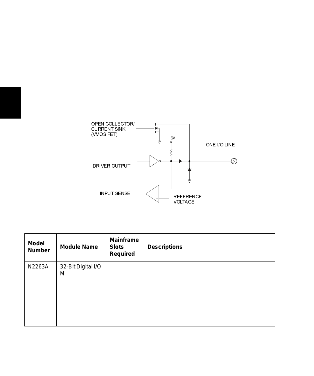
Digital I/O Mod ule s
The digital I/O modules provide high-density digital input/output
capabilities in an easy-to-control form. The independent TTL-compatible
inputs and outpu ts mak e it well-suited for monitorin g and controlling
devic e s compactly and cost-effecti vely. Typicall y, the dig i tal outpu ts are
used to provide drive for relatively high current devices such as
solenoids, relays and small motors. Th e d igital inputs are used to
monitor devices such as micro-sw itches. A simplified schematic of a
sing l e digit a l input and output l i ne is shown below.
OPEN COLLECTOR/
CURRENT SINK
(VMOS FET)
DRIVER OUTPUT
+5V
ONE I/O LINE
The table b el ow lists th e available d igita l I/ O modu les.
Model
Number
Module Name
N2263A 32-Bit Digital I/O
Module
44474A 16-Bit Digital I/O
Module
64
INPUT SENSE
A Simple Digital I/O Circuit
Mainframe
Slots
Descriptions
Required
1 The module offers 32-bidirectional I/O lines and
three handshake lines for sensing and control of
external devices up to 42 V, 600 mA. All lines
are TTL-compatible.
1 The module offers 16-bidirectional I/O lines and
four handshake lines for sensing and control of
external devices up to 30 V, 125 mA. All lines
are TTL-compatible.
REFERENCE
Page 65

Chapter 3 System Overview
Plug-in Modules Overview
Multifunction Modules
A multifunction modu le combines two or more functions such as MUX,
GP, Matrix, Digital I/O or DAC onto a single module, making it possible
to implement a complicated switching application with fewer modules.
Therefore, the cost is reduced by minimizing the number of mainframes
and modules requ ired.
Each separate function on a multifunction module can be operated
independently. Fo r example, an A gilent N2265A can be used as both a
4 x 4 matrix module and a 16-bit digital I/O module.
The table below lists the available multi fu nc tio n mod ules.
4
3
Model
Number
N2264A 12-Channel GP +
N2265A 4 x 4 Matrix +
Module Name
3-Channel Highcurrent GP +
16-Bit Digital I/O
Module
16-Bit Digital I/O
Module
Mainframe
Slots
Required
1 Non-
1 Latchi ng T he module provides 4 x 4 2-wire
Relay
Type
latching
Description
The module provides 12-channel
SPST (Single-pole Single-throw)
GP relays for signals up to 200 V, 1
A, 3-channel high-current GP
relays for signals up to 125 V, 5 A,
and 16-bit digital I/O for sensing
and control of external devices up
to 42 V, 600 mA.
matr ix for signals up to 200V, 1A,
and 16-bit digital I/O for sensing
and control of external devices up
to 42 V, 600 mA.
65
Page 66

Chapter 3 System Overview
Plug-in Modules Overview
Opti ca l M odules
The Agilent N228 0A an d N 2281A are optical switch modules. The table
below lists the information about these three optical modules.
3
Model
Number
N2280A Optical Switch Quad 1-to-
N2281A Optical Switch Dual 1-to-
Module Na me
2 MUX Module
4 MUX Module
Mainframe
Slots
Required
2Non-
2Non-
Relay
Type
latching
latching
Description
Four 1-to-2 Optical
Switches
Two 1-to-4 Optical
Switches
66
Page 67

Chapter 3 System Overview
Channel and Slot Addressing
Channel and Slot Addressing
A channel refers to an individual relay on a switching module, or an
individual bit/port on a digital I/O module. The channel address is in the
form of snn, where s repres ents sl ot number and nn represents a channel
number.
For all mainframes, slot 0 refers to the 3499A/B/C control board. Valid
slot numbers are:
3499A s lots 0 through 5
3499B s lots 0 through 2
3499C slots 0 through 9
The chan ne l nu m b e r, nn, is plug-in module dependent. Detailed
information about channel numbers of individual plug-in modules is
given below and on the following pages.
Plug-in Module
N2260A
40-Channel MUX Module
N2261A
40-Channel GP Relay Module
N2262A
4X8 Matrix Module
a. The N2260A and N2266A can be only be used as a 40-channel 2-wire MUX modulein 3488 mode.
b. A channel numb er on a mat rix modu le is for me d in Slot- Ro w- Col umn forma t , i.e. , chan nel ad dr e ss s23 mean s row 2,
colum n 3 in S l ot s.
a
Channel Addressing (snn)
s = Slot Number; nn = Channel Number
2-Wire Mode: s00, s01...s38, s39
s00, s01, s02, s03... s37, s38, s39
Row 0, 1, 2, 3; Column 0, 1, 2, 3... 6, 7
(s00, s01, s02... s07; s10, s11, s12... s17;
s20, s21, s22... s27; s30, s31, s32... s37)
b
4
3
67
Page 68

Chapter 3 System Overview
Channel and Slot Addressing
3
Plug-in Module
N2263A
32-Bit Digital I/O Module
N2264A
12-Channel GP Relay +
3-Channel High-current GP Relays +
16-Bit Digital I/O Module
N2265A
4x4 Matrix +
16-Bit Digital I/O Module
N2266A
40-Channel MUX Module
b
Channel Addressing (snn)
s = Slot Number; nn = Channel Number
Individual Bits: s00, s 01, s02... s30, s31
8-Bit Ports: s00, s01, s02, s03
16-Bit Ports: s04, s05
32-Bit Port: s06
12 GP Relays: s00, s01 , s02... s10, s11
3 High-current GP Relays: s20, s21, s2 2
16-Bit Digital I/O:
Individual Bits: s30, s 31, s 32 ... s44, s45
8-Bit Ports: s30, s31
16-Bit Port: s32
4x4 Matrix:
Row 0, 1, 2, 3; Column 0, 1, 2, 3
(s00, s01, s02, s03; s10, s11, s 12, s1 3;
s20, s21, s22, s23; s30, s31, s32, s33)
a
16-Bit Digital I/O:
Individual Bits: s40, s 41, s42... s54, s55
8-Bit Ports: s40, s41
16-Bit Port: s42
2-Wire Mode: s00, s01...s38, s39
N2267A
s00, s01, s02... s07
8-Channel High Current GP Module
N2268A
s00, s01, s02, s03; s10, s11, s 12 , s13
50Ω 3.5 GHz D ual 4-to-1 MUX Module
a. A chann el number on a m a trix module is formed in Slot -Row-Column format, i.e., channel address s23 means row 2,
colum n 3 in S l ot s.
b. The N2260A and N2 266A can only be us ed as a 40-channel 2-wire MUX module in 3488 mode .
68
Page 69

Chapter 3 System Overview
Channel and Slot Addressing
Plug-in Module
N2270A
10-Channel HIgh Voltage MUX Module
N2280A
Optical Switch Quad 1-to-2 M UX Module
N2281A
Optical Switch Dual 1-to-4 MUX Module
4-Bit Built-in Digital I/O
(slot 0 control module)
44470A
10-Channel MUX Module
44470D
20-Channel MUX Module
44471A
10-Channel GP Relay Module
44471D
20-Channel GP Relay Module
44472A
Dual 4-Channel VHF Module
Channel Addressing (snn)
s = Slot Number; nn = Channel Number
s00, s01, s02... s07
s00, s01; s10, s11; s20, s21; s 30 , s31
s00, s01, s02, s03;s10, s11, s12, s13
Individual Bits: 091, 092, 093, 094
4-Bit Port: 090
s00, s01, s02, s03... s08, s09
s00, s01, s02, s03... s18, s19
s00, s01, s02, s03... s08, s09
s00, s01, s02, s03... s18, s19
Group 0: s 00, s 01, s 02, s03
Group 1: s 10, s 11, s12, s13
4
3
44473A
4x4 Matrix Module
a. A chan nel number on a mat rix module is form ed in Slot-Row- Column fo rmat, i.e., cha nnel address s23 means row 2,
colum n 3 in S l ot s.
Row: 0, 1, 2, 3; Column: 0, 1, 2, 3
(
s00, s01, s02, s03; s10, s11, s12, s13;
s20, s21, s22, s23; s30, s31, s32, s33)
a
69
Page 70

Chapter 3 System Overview
Channel and Slot Addressing
3
Plug-in Module
44474A
16-Bit Digital I/O Module
44475A
Breadboard Module
44476A
3-Channel 13 GHz Microwave
Switch Module
44476B
2-Channel 26 GHz Microwave
Switch Module
44477A
7-Channel Form-C Relay Module
44478A
50 Ω 1.3 GHz MUX Module
44478B
75 Ω 1.3 GHz MUX Module
Channel Addressing (snn)
s = Slot Number; nn = Channel Number
Individual Bits: s00, s 01, s02... s14, s15
8-Bit Ports: s00, s01
16-Bit Port: s02
N/A
s00, s01, s02
s00, s01
s00, s01, s02, s03, s04, s05, s06
Group 0: s00, s01, s02, s03
Group 1: s 10, s 11, s12, s13
Group 0: s 00, s 01, s 02, s03
Group 1: s 10, s 11, s12, s13
70
Page 71

Chapter 3 System Overview
Factory Default and Reset States
Factory Default and Reset States
The table on the next page shows the settings of the instrument after a
reset.
•You can reset the instrument either by pressing
Shift + Card Reset o n the front- pa nel, or with a RESET command
over the remote in terface.
•If a module is accidentally remo ve d o r installed while the
instrument power is on, the instrument will preform a reset.
3488 Mode Defaults
Item Factory Default Reset
4
3
Interface GPIB/488 GPIB (Address 9) Keep current setting
RS-232
System Mode SCPI Mode SCPI Mode Keep current setting
3488A Mode Keep current setting
System-Related Display State On On
Stored State Empty Keep current setting
Error Queue Empty Cleared
Module-Related Switching Channels Open Open
Digital I/O Ports Input Input
Card Pair None None
Scan-Related Scanning None Stop scan in progress
Scan List Empty Empty
Channel Delay
(seconds)
Trigger Out Pulse Disabled Disabled
b
00
Keep current setting
a
a. Curr ent setting inc l ud es th e selectio n of the G PI B int e rface and its a dd r es s se tting.
b. RS-232 interface CANNOT be used in 3488A mode.
71
Page 72

3
72
Page 73

4
4
Features and Functio ns
Page 74

4
Features and Functions
This chapter provides details about particular functions and features of
the Agilent 3499A/B/C Switch/Control System. The sections in this
chapter describe the features using both the fro nt-panel and the remo te
interface using SCPI commands. The examples in this chapter are
general. For specific procedures using the front panel refer to Chapter 2.
For SCPI command information refer to Chapter 5. The following
sections are included in this chapter:
•
Monitoring a Channel or a Slot, on page 75
•
Switching a Relay Channel, on page 77
•
Scanning, on page 78
•
Digital I/O Operation, on page 84
•
State Storage, on page 94
•
Error Conditions, on page 96
•
Self-Test, on page 96
•
Display Control, on page 97
•
Relay Cycle Counts, on page 98
The following con ventions are used for the front-panel operation.
•
All keys on the front-panel keyboard are expressed in bold font and
normally associated with a “press”. For example, press Mon.
•
All the front-panel display annunciators are expressed in bold font
followed by an “annunciator”. For example, MON annunciator.
•
The information shown on the front-pa nel dis play is enc losed wi thin a
pair of quotation mark s.
•
Shift + Recall1 indicates the sequential operation: first press Shift,
then press Recall.
1
Also applicable to keys Card Reset, Scan, and S.List.
74
Page 75

Chapter 4 Features and Functions
Monitoring a Channel or a Slot
Monitoring a Channel or a Slot
You may need to continuously monitor the current status of a particular
switching channel, a digital I/O port, or an entire plug-in module. This is
especially useful when developing and debugging remote interface
comma nd s or watching fo r an important signal.
•
To monitor a channel or a port, specify the channel or port number.
To monitor a plug-in module, specify the slot number. The displayed
information is module type dependent as shown o n t he next page.
•
Front-Panel Operation: To se lect a channel, a digital I/O port, or a
slot, press Mon. The MON annunciator lights up. Press Mon again
to exit this state.
4
4
MUX 101
DIN
1:0 , , , , , ,6, , ,9,
00: H255 L254. 4
If only part of the channel status on the module can be displayed at
one t i me, press Enter to display the next part.
•
Remote Interface Operation:
OUTPUT 709; “VIEW 103”
OUTPUT 709; “VIEW 431”
OUTPUT 709; “CMON 2”
OPEN
Monitor a switc hing channel 101.
400255
2
Monitor a DIO Port 400.
Monitor a MUX or GP module.
Monitor a DIO module.
! Query the state of a relay
channel 103.
! Query the state of a bit
channel 431.
! Monitor the module in
slot 2.
75
Page 76

Chapter 4 Features and Functions
Monit oring a Channel or a Slot
Example MON Display Des criptio n
4
1:0,,,,,,6,,,9, 2
ROW 3:,1,,3,,,6,7 3
0;,,3,COL 3, 3
00:H255 L254. 4
DIO 12 090
DOUT 0 091
The display for a multiplexer or a GP relay module. This
display indic at es t hat the m o nitored module is in Slot 2 and
channels 10, 16, and 19 are closed.
The display for a matrix module. The top display is the row
information, indicating that the relays on Row 3, Columns 1, 3,
6 and 7 of the module (in Slot 3) are closed. The lower display
is the column information, indicating that relays on column 3,
row 0 and 3 are closed.
The display for a digital I/O module. The first 2 digits on the left
(“00” in this case) represents the “L” 8-bit port address. Adding
one to this value, the “H” 8-bit port address is obtained. Data
with a trailing decimal point indicates that the last operation on
that port was a WRITE, data without a trailing decimal point
indicates that the last operation on that port was a READ. This
display sh ows that th e data last read from Port 401 is 255 and
the data last written to Port 400 was 254.
The top display is for the built-in digital I/O Port 090 (controller
module) and the data from the last operation. The lower
display indicates that data last written to th e bit channel
091 is 0.
ROW 0:,1,,3, 5
00:H255 L254. 5
For a multifunction module, the first fu nction on the module is
displayed , then the next. This display is an example of a
multifunction module with matrix and DIO functions (in slot 5).
76
Page 77

Chapter 4 Features and Functions
Switching a Relay Channel
Switchi ng a Re la y Chan ne l
Switch modules can be used to route signals to and from your test
system. Thi s is achi ev ed by c l osin g or open ing the relay channels on
these modules.
•
From the front-panel, you can open or close one relay channel at a
time. How eve r, o ver the GPIB interface, multiple relay channels can
be operated by a single command if a channel list is specified. In
addition, these open or closed states can be stored, and a stored
channel setup can be included in a scan list (see “State Storage” on
page 94).
•
Whenever a switch module is reset, all of the closed rela y channel s on
the module will be open ed.
•
Whenever the instrument i s turned on or reset, all of the closed relay
channels in the instrument will be opened.
4
4
•
Front-Panel Operation: Select a channel, press Open or Close.
Select a slot, press and hold Card Reset to open all channels on the
selected module.
Press Shift, then press and hold Card Reset to open all channels in
the instr um e n t.
•
Remote Interface Operation: The following commands open and close
multiple channels on the modules in slots 1 and 2.
OUTPUT 709; “OPEN 101,102,207”
! Open multiple ch annels.
OUTPUT 709; “CRESET 1”
OUTPUT 709; “CLOSE 101,102,207”
! Open all channels on the
module in slot 1.
! Close multiple channels
77
Page 78

4
Chapter 4 Features and Functions
Scanning
Scanning
The Agilent 3499A/B/C can scan switching channels, digital I/O bit
channels, and stored channel setups in a scan list. When a scan starts,
the first channel in a scan list is closed. The chan nel is then opened and
the next channel in the list is closed. This process repeats for all
channels in the scan list. You can sweep through a scan list more than
once. You can also synchronize scanned channel closures with external
measurement devices.
Rules for Scanning
•
A scan list must be specified before initiating a scan. One or more
switching channels, digital I/O bit channels, and/or previously stored
channel setups can be included in a scan list. The order of the
channels in the scan list determines the order of the channels to be
scanned.
•
If any plug-in module is installed or removed while the instrument is
operating, the instrument will automatically perform a reset and the
curren t sc an list is cl eared.
•
If a scan list contains a non-existing channel, the scan cannot be
performed and an error will occu r.
•
If a scan list contains a channel on a digital I/O module that is not
configured to handshake mode #1 or mode #2 (see page 86), the scan
cannot b e perf orm e d and an err o r will occur.
•
If a mismatch between a stored channel setup in the scan list and the
current hardware configuration is found, a scan cannot be performed
and an error will occu r. W hen a stored se tup is inc lud e d in the scan
list, the stored setup is recalled and the next channel in the scan list
is switched.
•
When a scan is aborted, the channel last scanned before the
interruption will remain closed. Aborting a scan does not affect the
present scan configu rat i on. A scan cannot resume from where it is
interrupted . T o initiate a new scan, the channels in the scan list will
be scanned from the begin nin g of the scan list.
•
A scan list may contain up to 200 entries.
78
Page 79

Chapter 4 Features and Functions
Scanning
Creati ng a Sc an List
Before initiating a scan, a scan list must be set up. The instrument scans
the specified ch annels automatically i n the sam e ord e r of the scan list .
•
The scan list is automatically cleared whenever the instrument is
turned off or reset. You can also clear the scan list by pressing
Shift+S.List.
•
Front-Panel Operation: Press S.List, the CONFIG annunciator will
light. The display will show “ADD TO SCAN”. Press Enter to begin
building the scan list. Select each desired channel and press Enter to
add the channel to the scan list. As channels are added, an asterisk is
shown in the display to indicate the channel is a part of the scan list.
4
ADD TO SCAN
Press S.List. Press Enter.
SELECT 101
SELECT
SELECT 203
•
Remote Interface Operation: You may use single channels, ra nges of
channel, or stored setups in the scan list. Set up a scan list with one
command as follows:
10 OUTPUT 709; “SLIST 100-109
20 FOR I = 1 to 10
30 OUTPUT 709; “STEP”
40 OUTPUT 709; “DELAY 20”
50 Next I
Note Stored states may be used in scan lists. Stored states are discussed in
more detail begin ning on page 94.
101
*
Select a channel to add.
Press Enter.
Select the next ch annel to add.
“! Create a scan list.
! Step through the scan list.
! Add 20 ms time delay.
4
79
Page 80

Chapter 4 Features and Functions
Scanning
Config ur i n g a Sc an
You can use delay times to control a scan.
•
You can s pecify a delay time (from 0 to 99999.999 seconds, with 1 ms
resolution) between when a channel is closed and when the next
operation begins (and, if configured, a trigger out pulse is sent). The
delay time can be set individually for each channel in the scan list, or
one delay can be set for all channels in the scan list. Note that, even if
the trigger source is set to IMMediate, the scan list will not advance
until the delay time is met.
•
Front-Panel Operation: Use the S.List menu to set the scan delay
time as shown below.
4
DELAY TIME
00000.0000 SECS
3499
•
Remote Interface Operation:
OUTPUT 709; “DELAY 2000; CHAN 101”
Turn the knob to select DELAY TIME.
Press Enter.
Use arrow keys and knob to
select the delay t i me. Press Enter.
Press S.List to exit the menu.
! Set a 2 second de la y time
80
Page 81

Chapter 4 Features and Functions
Scanning
Performing a Scan
Once you set up a scan list and configure the scan, the actual scan can be
performed.
•
If a scan list contains a non-existing channel, the scan cannot be
performed and an error will occu r.
•
If a scan list contains a channel on a digital I/O module that does not
work in Mode #1 or Mode #2, the scan cannot be perform ed and an
error will occur (see page 86 for more information about modes).
•
If a stored channel setup in the scan list does not match the current
hardware configuration , the s can cannot be perform ed and an er ro r
will occur.
4
•
Front-Panel Operation: Press Scan
Stop a scan in progress by pressing Shift+Scan. The last channel
closed in the scan list will remain closed. You cannot pause and then
continue a scan. You must start the scan operation over.
Press Step to start and step through the chan nels in the s can li st, one
channel at a time.
•
Remote Interface Operation: Use the STEP command to begin a scan.
If you abort a scan in progress, the last channel closed in the scan list
will remain closed. You cannot pause and then continue a scan. You
must start the scan operation over.
OUTPUT 709; “STEP” !Step into the scan list.
to begin the scan operation.
4
81
Page 82

Chapter 4 Features and Functions
Scanning
Using External Triggering
Two control lines are provided in the rear panel mini-DIN connector:
external tr igg er i n and external trigger out. These lines can be used
individually or combined to synchronize a scan list with an external
instrument (such as a DMM). The figure below shows this connection.
The 3499A/B/C can be c onfigured to output a trigger pul se t o notify the
external inst rument whenever a channel is close d.
4
Agilent 3499B
VM Complete Out
1
3
6
7
(Ext.Trig.In)
•
In addition to the Ext.Trig.In and Ext.Trig.Out pair pro vided on the
2
4
5
(Ext.Trig.Out)
8
External DMM
Ext Trig In
rear panel of the mainframe, the EI (external increment) and CC
(channel closed) pair on a 44474A module can also be used to
synchronize. Specify either Slot 0 or the slot in which a 44474A
module is installed to indicate whic h lines are to be u se d.
•
Both the built-in trigger lines and the EI/CC lines on the 44474A are
TTL compatib l e .
•
Once enable d, the sele cted trig ge r-in line is immediately ready to
accept the trigger signal from the external instrument. Enabling or
disabling a trigger source from the front-panel sets both the trigger in
and trig ge r out functions.
82
Page 83

Chapter 4 Features and Functions
Scanning
•
Front-Panel Operation: Press Menu, use the knob to select
“CONF EXT TRIG” and press Enter. Select either s l ot 0 (built-i n
external trigger) or the slot where a 44474A is installed and press
Enter. E nable or disable th e pai r of trigg e r lin es an d press Enter.
Press the Menu key again to exit the menu.
Press S.List, select “CONFIG SCAN”, and configure the arm source
or trigger source as either EXT or MIX.
•
Remote Interface Operation: The following code se gm e nt will set up
the 3499A/B/C to synchronize with an external instrument.
4
OUTPUT 709; “DMODE 0,1,0,1”
! Enable a tri gger pulse on the
rear panel Min i DIN
connector.
4
83
Page 84

4
Chapter 4 Features and Functions
Digital I/O Operation
Digital I/O Oper a tion
The digital input/output is well-suited for monitoring and controlling
external devices. You may use the built-in digital I/O bits or port (on the
rear panel), one or more digital I/O modules, or a multifunction modules
with a DIO function. In the following context, multifunction modules
refer to those with a DIO function.
•
The built-in digital I/O (control board) consists of four bits which can
be operated either independently as four bit channels (numbered 091
through 094) or as one 4-bit port (numbered 090).
•
The plug-i n digital I/O modules and multifunction mod ules usually
consist of several 8-, 16-, and/or 32-bit ports. These ports can be
operated independently, which means one port can be used for outpu t
operation, while others can be used f or input. However, all bits with in
a same 8-bit port ar e dependent. If one bit of a port is used for input
or output operation, t hen all other bits of the same port can only be
used for the same operation.
Note For more information about a specific digital I/O module, refer to the
Agilent 3499A/B/C User’s Manual (shipped with the instrument) or visit
www.agilent.com.
Digital I/O Conf ig u r a t io n
•
Parameters such as flow control mode, control line polarity (PCTL),
flag line polarity (PFLG), and I/O direction line polarity, are all
configured for the plug-in digital I/O modules and multifunction
modules. However, these DO NOT apply to the built-in 4-bit
digital I/O (on the rear panel).
•
The data line polarity of any 8-bit port (or the 4-bit built-in port) can
be configured from the front-panel. However, using the remote
interface, the data line polarity of any ports (8-, 16-, or 32-bit) can be
configured.
•
Data display format of any 8-bit port, binary or decimal (default), can
only be specified from the front-panel. Once specified, the format
applies to all input and output operations on the same port.
•
When the instrument is turned on or reset, the handshake mode is
set to Mode #1 and the polarities of all configured lines are positive.
More information about handshak e modes is given s tarting on
page 86.
84
Page 85
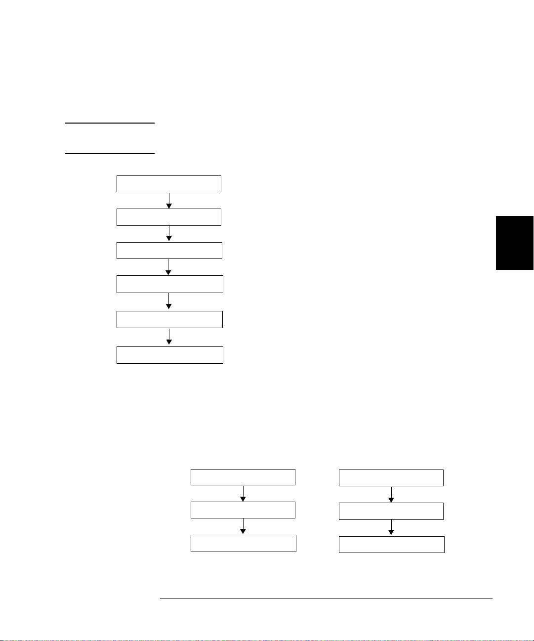
Chapter 4 Features and Functions
Digi tal I /O Operat i on
•
Front-Panel Operation: Select a digital I/O module and press Mode.
“CONFIG DIO” is shown in the display. Press Enter to show the
second-level menu and begin the configuration.
Note Be sure to select the module, not a port or bit. The options on this menu
are only available when the mod ule i s selected.
N2263A
CONFIG DIO
MODE 1
CONT POL POS 4
FLAG POL POS 4
I/O PO L P O S 4
Press Mode again to exit the menu.
Configure a port. Select a digital I/O port, t hen press Mode, the
CONFIG annunciator lights up. When “DATA POLARITY” appears
in the display, press Enter to se t data line polarity and/or use the
knob to select “DISP FORMAT” and press Enter to set data display
format for the port.
4
4
4
Select a DIO module.
Press Mode.
Select flow control mode. Press Enter.
4
4
Select the control line polar ity. Press Enter.
Select th e flag line polarity. Press Enter.
Select the I/O direction line polarity. Press Enter.
DIN
DATA POLARITY 401
NEG POLARITY 401
401
or
DIN 401
DISP FORMAT 401
BINARY 401
85
Page 86

Chapter 4 Features and Functions
Digital I/O Operation
•
Remote Interface Operation: Set the flow control parameters using the
following 3488 command. This example assume a digital I/O module
is installed in slot 4.
OUTPUT 709; “DMODE 4,1,0,1”
! Set the flow control to Mode
#1 and the polarity of all
lines to default va lues.
About Flow Contro l Modes (Handshake)
Five flow control modes are available for Digital I/O operat i ons. Some
modes use one or more of the three flow control lines: I/O Direction ,
4
Note The p o larity of the flow control li n es is assumed to be p ositiv e (the
PFLG, and PCTL. Select the flow control you need for your digital input/
output applications.
default) in the follo wing diagrams and discussio ns .
Mode
Number
Handshake
Mode
Definition
1 Sta tic m ode #1 Default handshake mode.
2 Static mode #2 Read what was written.
Notes
3 Read or Write
and strobe
4 Read and write
strobe
5 Full h andshake If you set a port to this mode, you cannot use
86
If you set a port to this mode, you cannot use
the port in a scan list.
If you set a port to this mode, you cannot use
the port in a scan list.
the port in a scan list.
Page 87

Chapter 4 Features and Functions
Digi tal I /O Operat i on
Static Mode #1
Static Mode #1 is the default mode. In this mode, data is transferr ed
statically, there is no read or write strobe pulses or handshaking. The I/O
Direction line is active and indicates direction of transfer. This is shown
in the following timing diagrams.
Write Operation
(CLOSE, DWRITE, etc.)
DATA LINES
I/O DIRECTION
t1 (>1ms )
DATA VALID
t1 = I/O inp ut to dat a
valid (1ms minimum)
Approximately 1 ms after the I/O direction line goes to a lo w
state, the digit a l I/ O mo d ule takes control of the d a ta lines.
Read Operation
(DREAD, etc.)
DATA LINES
I/O DIRECTION
t1 t2
100µs150µs
DATA VALID
t1 = D a ta b us floated
(
t2 = I/O inp ut to da ta
100 µs after the 3499A/B/C is instructed to read the data lines, it releases
control of the lines and the I/O direction line goes to a high state. 150 µs
later the data is actually read (latched).
4
4
to I/O inp ut
100 µs minimum)
latched (150 µs
minimum)
Static Mode #2
Static Mode #2 acts just like Mode #1 except the output lines are not
disabled du rin g an input operatio n. This means that if a p o rt i s written
to and the n read from , the data read will be that which was just writ te n
to it. It is possible, however, that external devices might load the lines
and cause a false read.
Timing for the I/O direction line is as shown in Mode #1 for write
operations. For read operations, t he I/O direction line does not change.
87
Page 88
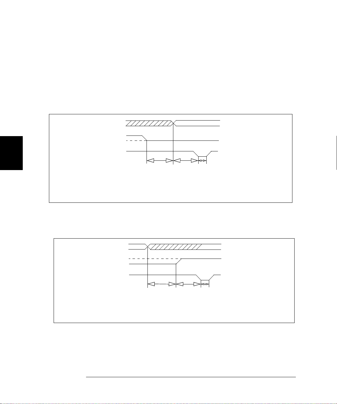
Chapter 4 Features and Functions
Digital I/O Operation
Read or W rit e and Strobe Mo de #3
In this mode, the I/O d irection line is still used to ind icate direction of
transfer (input or output) but the PCTL (Peripheral control) line is used
to strobe the data.
During a write operation , where the 3499A/B/C writes the data to so m e
external device, the s trobe p uls e sig nifies that the data on the 16 o r 32
data I/O lines is valid. This is shown in the following timing diagram.
4
Write Operation
STROBE (PCTL LINE)
DATA LINES
I/O DIRECTIO N
t1
1ms
DATA VALID
t2
st320 µs
25
µ
t1 = T i me fro m I/O li n e
low to o u tp ut e n ab le
(1 ms minimum)
t2 = T ime from outp u t
ena b l e t o s t a r t o f
s
trobe (25 µs
minimum)
t3 = Strobe pulse width
(20 µs
A S t robe pulse signifies that the da t a on the data lines is valid. During a
write operation , the device receiving the data is triggered by the strobe.
The Strobe pulse is used durin g a read operation to signify that the
3499A/B/C has completed the read operation. This is shown in the
following diagram.
t2
DATA VALID
t1 = T ime from outp u t
disable to I/O line
high (100 µs m in)
t2 = T i me f r o m I /O l ine
hig h to star t of
Strobe (150 µs
minimum)
t3 = Strobe pulse w idth
(20 µs
Read Op eration
STROBE (PCTL LINE)
DATA LINES
I/O DIRECTIO N
t1
100
s
µ
150 µst320 µs
minimum)
minimum)
When used during a Read operation, the Strobe pulse signifies that the
3499A/B/C has latch e d (read ) the d ata from the da ta lines.
88
Page 89
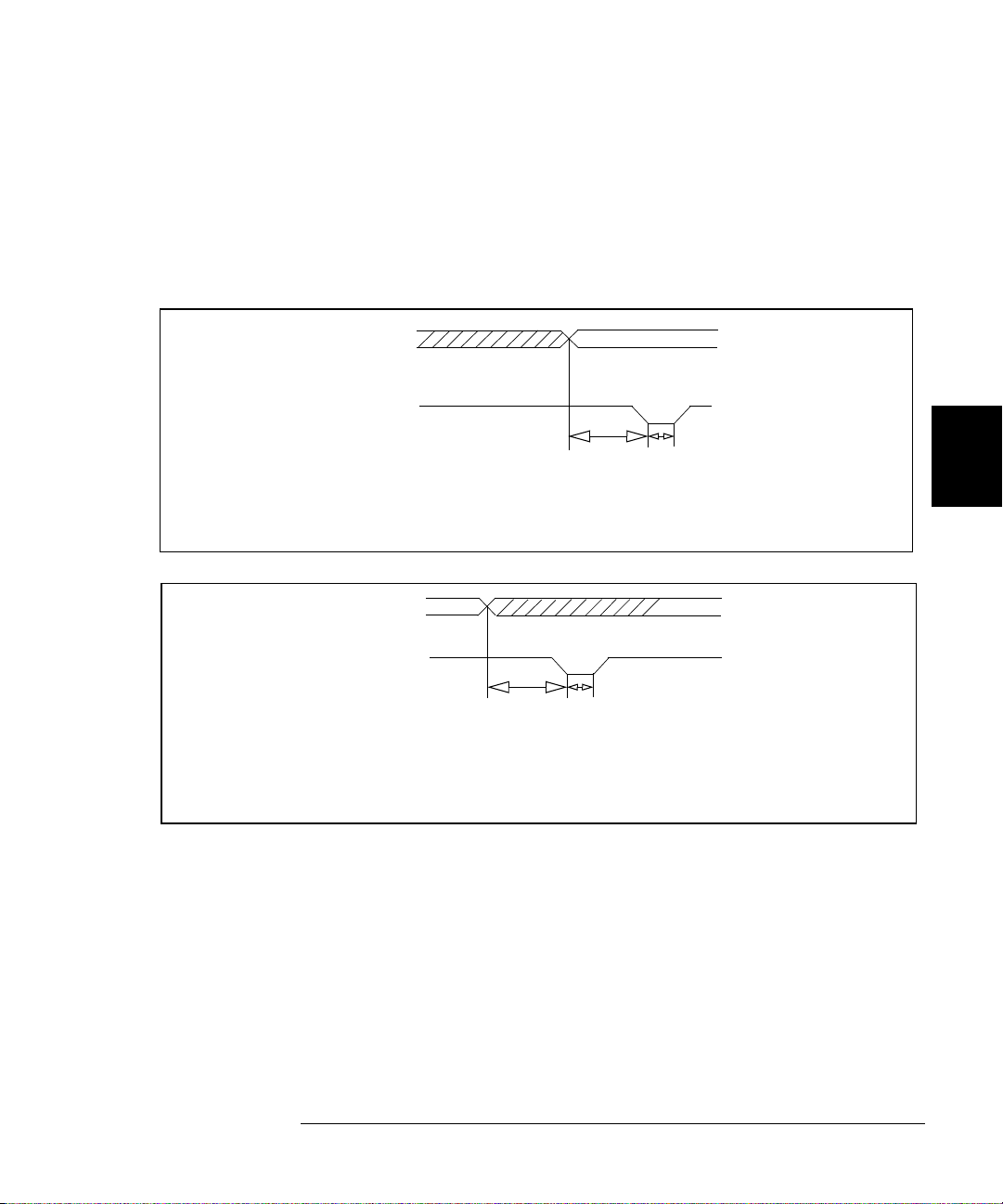
Chapter 4 Features and Functions
Digi tal I /O Operat i on
Read and Write Strobe Mode #4
Read and Wr ite Strobe Mode #4 uses the I/O direction line as a Strobe
pulse to indicate writing operations. T h e P CT L line is used to ind ic ate
Read operations. It is thus similar to the R/W and Strobe Mode #3 except
separate control lines are used for the Strobe pulses and there is no I/O
direction line.
DATA LINES
W r it e O p e ra tio n
IO DIRECTION (WR)
DATA VALID
t1
40 µst220 µs
t1 = Tim e from d ata
valid to write
Strobe
(40 µs minimum)
t2 = Strobe pulse w idth
(20 µs minimum)
The IO Direction line is used to indicate that the data is valid o n the data bus li ne s.
IO Direction is used to trigger the receiving device.
DATA VALID
t1 = Time f rom output
disable to read
St r o b e ( 1 0 0
minimum)
t2 = Strobe pulse w idth
(20 µs minimum)
µs
Read O peration
DATA LINES
PCTL (RD) LINE
t1
100 µst220 µs
As in Mode #3, the PCTL (RD) line is used to indicate to the sending
device that the 3499A/B/C has latched (read) the data.
4
4
89
Page 90

Chapter 4 Features and Functions
Digital I/O Operation
Full Handshake Mode #5
Handshake Mode #5 provides a complete tw o wire h andshake with a
data direction line. During write operations, the PCTL line indicates that
output data is valid; during read operations, it indicates that the digital
I/O module (i.e. N2263A) is “ready for data”. The PFLG line is used by
the peripheral device to indic ate “ready for data” during wri te operati ons
or “data val id” for read operations.
For this discussion, write operations mean the plug-in digital I/O module
is controlling the data lines. Read operations mean external devices
control the data lin es and the digital I/O module reads the data and
controls the PCTL/RD line.
4
W rite Operation
DATA LINES
I/O DIRECTION
PCTL LINE
PFLG L IN E
DATA VALID
t1
1
mst240 µst330 µst440 µst535 µs
t1 = T i me f r o m I /O l ine
low to ch eck fo r
PFLG low
(
1 ms minimum
t2 = Time from PFLG
low to d a ta v a lid
(40 µs minimum)
t3 = Time from data v a lid
to PCTL low
(30 µs minimum)
t4 = Time from PCTL low
to check for PFLG
high (40 µs minimum)
t5 = Time from PFLG
to PCTL high
(35 µs minimum)
)
The complete handshaking sequence for Mode #5 is as follows: The 3499A/B/C checks
to see if the rec ei ving device has set the P FLG line low, this ind ica tes the re ceiving
device is ready to accept data. When PFLG is low, the 3499A/B/C sets the data on the
data bus and sets PCTL low. The 3499A/B/C then waits for the receiving device to set
PFLG high, indicating that it has latched the data. To com ple te the handshak e , the
3499A/B/C sets PCTL hig h.
90
Page 91
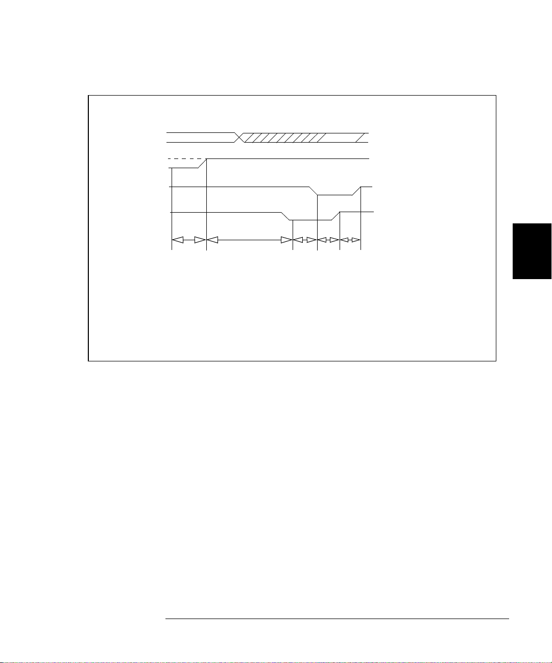
Chapter 4 Features and Functions
Digi tal I /O Operat i on
Read O peration
DATA LINES
I/O DIRECTION
PCTL LINE
PFLG LINE
t1
100 µs
DATA VALID
t2
45 µs
LATCHED
t3
50 µst440 µst535 µs
t1 = T ime fro m outpu t
disable to I/O line
high (100 µs minimum)
t2 = T i me from I /O line
high to check for
PFLG low
(45 µs minimum)
t3 = Time from PFLG low
to ch eck for PC T L
low (50 µs minimum)
t4 = Time from PCTL low
to check PFLG
high (40 µs minimum)
t5 = Time from PFLG
high to PCTL high
and data latch ed
(35
µs
minimum)
As with the Write operation, the 3499A/B/C begins by testing PFLG for a
low state, i ndicating that the data is valid. When PFLG is low, t he
3499A/B/C sets PCTL low and waits for PFLG to go high. Th e 3499 A/B/C
will set PCTL high to indicate that it has completed the data read operation.
Data on the data bus must remain valid until after the 3499A/B/C sets
PCTL high .
4
4
91
Page 92

Chapter 4 Features and Functions
Digital I/O Operation
Digital Inpu t Ope r at ion
•
From the fron t-p ane l, you can read dat a from the b uilt-in digital I/O
bits/port (numbered 090 through 094) or any one of the 8-bit ports on
a digital I/O module or multifunction module.
•
From the remote interface, you can read data from the ind ividual bit
channels and 8-, 16 -, or 32-bit ports on a digital I/O module o r
multifunction module, as well as from the built-in digital I/O bits/port
(numbered 090 through 094).
•
Instrument reset will set all digital I/O ports in the instrument as
input ports. Pressing Card Reset or issuing a RESET command will
set all ports on the specified module as input ports (ports on other
modules are not affected).
4
•
Front-Panel Operation: Select an 8-bit digital I/O port, press Rea d to
read the data from the port. Th e dat a can be displayed as either
decimal or binary (see page 33).
•
Remote Interface Operation: Use the following command to read an
individual bit (bit 6) on a module in slot 4. A “0” (bit cleared) or a “1”
(bit set) will be returned.
OUTPUT 709; “DREAD 402” ! Read data from Port 402.
OUTPUT 709; “VIEW 403”
The range of possible returne d values is show n:
Parameter Decimal Range Hex range
BYTE 0 to 255 00
WORD -32768 to 32767 -8000h to 7FFF
LWORD
WORD values greater then 32767 and LWORD values greater then
31
for (2
complement form.
-1) are returned as negative numbers. These values are in 2’s
31
to (231 -1)
-2
! View a bit channel 4.
to FF
h
-80000000
to 7FFFFFFF
h
h
h
h
92
Page 93

Chapter 4 Features and Functions
Digi tal I /O Operat i on
Digital Output Op e r ation
•
From the fron t-p ane l, y ou can write da ta to t he built-in digital I/O
bits/port (numbered 090 through 094) or any one of the 8-bit ports on
a digital I/O module or multifunction module.
•
From the remote interface, you can write da ta to individual bit
channels and 8-, 16 -, or 32-bit ports on a digital I/O module o r
multifunction module, as well as to the built-in digital I/O bits/port
(numbered 090 through 094).
•
Instrument reset will set all digital I/O ports in the instrument as
input ports. Pressing Card Reset or issuing a RESET command will
set all ports on the specified module as input ports (ports on other
modules are not affected).
4
•
Front-Panel Operation: Select an 8-bit port, press Write, the data
from the last operation (read or write) will be displayed. Edit the data
to the desired value and press Enter to write the data to the port. To
cancel the write operation, press Write again instead of Enter. You
can edit the data in either binary or decimal form (see page 33).
•
Remote Interface Operation:
OUTPUT 709; “DWRITE 400,219” ! Write 219 to 16-bit Port 404.
OUTPUT 709; “CLOSE 401,407,411”
! Close bit channels 401, 407,
and 411.
OUTPUT 709; “OPEN 403,405,407”
! Open bit channels 403, 405,
and 407.
WORD values greater then 32767 and LWORD values greater then
31
for (2
complement form.
-1) are sent as negative numbers. These values are in 2’s
4
93
Page 94

Chapter 4 Features and Functions
State Storage
State Storage
The 3499A/ B/C p rovides the capabilit y to s to re setups, and then reca ll
them to put the instrume nt back into a known configuration.
Information that can be stored includes:
•
Status of all relay channels (open or closed)
•
Status of digital I/O ports (input or output, flow control, etc.)
•
Remote inter f ace se ttin gs (ad dre ss , baud, etc.)
Additionally, you can include a stored state in a scan list as a channel.
4
Firmware Revi sion Differences
State storage behavior differ s depending upon the firmware revision of
your 3499A/B/C (see page 55 ).
•
Firmware revision 1.0 must be upgraded. Please contact your nearest
Agilent Technologies Office for details.
•
Firmware revisions 2.0 and 3.0 allow up to 10 states to be stored.
Firmware revision 4.0 allows up to 40 stored states.
•
Stored states are lost if power is removed for firware revisions 2.0 or
3.0. Stored states are preserved when power is removed for firmware
revision 4.0.
•
Storage memory lo cations ar e number ed 01 to 1 0 for Firmw a re
revision 2.0 and 3.0. Memory locations are number 01 to 40 for
Firmware revision 4.0.
•
Before recalling a stored setup, the instrument verifies that all
module types and slot assignment match the setup. If a mismatch is
detected, an error (“RECALL FAILED”) will occur.
94
Page 95

Chapter 4 Features and Functions
State Storage
Firmware Revi sion Differences (continued)
•
An instrument reset does not affect the stored instrument setup
information .
•
All stored setups will be cleared if the system mode is changed (for
example, to SCPI mode).
•
Firmware revision 3.0 allows i nstrument operation in either SCPI or
3488 mode, not both. The mode is selected when the firmware is
loaded.
4
To Store an Inst rume nt State
Firmware revision 2.0 and 3.0 allow up to 10 stored states. Fi r mwa r e
revision 4.0 allows up to 40 stored states. Set the instrument to the state
you want to store.
•
Front-Panel Operation: To store an instrument setup, press
Shift + Recall, select a memory location, a nd pres s Enter. To cancel
the store operation, press Recall again instead of Enter.
4
•
Remote Interface Operation:
OUTPUT 709; “STORE 4”
Note Approximately 1 second is required to store an instrument setup into an
Agilent 3499A/B/C with Firmw are REV 4.0. To avoid errors in when
programming, be sure to allow a 1 second interval between the store and
recall operations.
! Store an instrument setup
To Recall an Instrument State
You can recall a previously stored instrument setup.
•
Front-Panel Operation: To recall a stored setup, press Recall, select
the memory location to be recalled, and press Enter. To cancel the
recall operation, press Recall again instead of Enter.
•
Remote Interface Operation:
OUTPUT 709; “RECALL 4”
! Recall the previously stored
channel setu p.
95
Page 96

4
Chapter 4 Features and Functions
Error Conditions
Error Conditions
When an error occurs, the 3499A/B/C will beep and the ERROR
annunciator on the front-panel light s up. Th i s indicates one or more
command syntax or ha rdware errors have been det e cted.
•
The error queue will be cleared automatically once you read the
queue, change the system mode, send the RESET command, or cycle
power on the instrument. However, a module reset will not clear t he
error queue.
•
Front-Panel Operation: Press View, select “ERROR”, and press
Enter. The sum of the values of the possible error conditions i s
displayed (refer to “Error Messages” on page 135).
•
Remote Interface Operation: In 3488 mode, the sum of the values of
the possible error conditions is recorded in the error queue. For
example, the returned value of “0003” means that both “Syntax
Error ” and “Exe cution Erro r” occurred ( refer to “E rror Messages” on
page 135).
ERROR
! Query the error register.
Self-Test
The 3499A/B/C can perform a self-test to verify that it is in proper
operation.
•
If the self-test is successful, “PASSED” will be displayed on the frontpanel. Otherwise , the reason of the failu re will be d isplayed. For
details of all self-test failures, refer to “Self Test Errors” on page 136.
•
Front-Panel Operation: Press Menu, use the knob to select
“SELFTEST”, and press E nter to perform a self-test.
•
Remote Interface Operation:
TEST
96
! Returns zero if the test is
succes sf ul, or non-zero if it
fails.
Page 97

Chapter 4 Features and Functions
Display Control
Display Control
You can turn off the 3499A/B/C display (for security or increased
processing speed for example). Y ou c a n also write a message of up to 13
characters to th e fron t- pa nel disp lay .
Note The display cannot be turned off from the front-panel.
•
When the display is turned off, the entire front-panel display goes
blank except for the ADRS and RMT annunciators (the ERROR
annunciator will also be on if there are errors), and all keys except
Local are locked.
•
If the display is turned off, pressing Local causes the instrument to
return to loc al oper atio n, the d isp lay wi ll b e tu rn ed bac k on.
•
The display is automati cally turn ed on when power is cyc l ed, or after
a RESET command.
•
When the display is on, you can send a message (up to 13 characters)
to display on the front-panel from the remote interface. If you attempt
to send more than 13 c har ac te rs, only th e first 1 3 char acters can be
displayed. The characters can be letters (A-Z), numbers (0-9), and
some special characters (“ ‘ space ( ) * + - , . : ; / \).
•
Remote Interface Operation:
OUTPUT 709; “DOFF”
OUTPUT 709; “DON”
OUTPUT 709; “DISP Scan finished.”
! Turn off the display.
! Turn on the display.
! Display the message on the
front panel.
4
4
97
Page 98

4
Chapter 4 Features and Functions
Relay Cycle Counts
Relay Cycle Counts
The Agilent 3499A/B/C can read and track the relay cycle counts on some
plug-in modules. This feature can be very useful in switching systems to
track relay failures and predict system maintenance requirements.
•
This feature is supported in 3488 Mode by the Agilent N2260A,
N2261A, N2262A, N2264A, N2265A, N2266A, N2267A, N2268A,
N2270A, and N2280A/81A modules.
•
The cycle counts of the tree relays (s98 & s99) on an N2260A or
N2266A can also be que r ied.
•
Front-Panel Operation: Press View, use the knob to select “RELAY
CYCLES”, and press Enter. Turn the knob to select the relay channel
of interest. The display shows the channel cycle count.
•
Remote Interface Operation: This feature is only available from the
front panel in 3488 mode.
98
Page 99

5
Remote Interface Reference
5
Page 100

Remote Interface Reference
This chapter describes 3488 mode commands applicable to th e Agilent
3499A/B/C Switc h/ Co ntr ol S yste m. T he chapter contents include :
•
Command Synt ax, on page 101
•
3488 Mode Command Qu ick Re ference, on page 102
•
3488 Mode Comm ands, on page 104
Note It is highly recommended that you use SCPI commands (in SCPI mode)
instead of 3488A commands (in 3488A mode). The SCPI commands allow
you to use all the features of the Agilent 3499A/B/C and the plug-in
modules. 3 488 mode com m an d s a re a subset and are provided for legacy
installations.
5
100
 Loading...