

Page 1

Agilent Technologies
Agilent Technologies
Agilent TechnologiesAgilent Technologies
3458A Multimeter
3458A Multimeter
3458A Multimeter3458A Multimeter
Assembly-Level Repair Manual
Assembly-Level Repair Manual
Assembly-Level Repair ManualAssembly-Level Repair Manual
Manual Part Number: 03458-90011
Printed in U.S.A
Page 2

AGILENT TECHNOLOGIES WARRANTY STATEMENT
AGILENT PRODUCT: 3458A Multimeter DURATION OF WARRANTY: 1 year
1. Agilent Technologies warrants Agilent hardware, accessories and supplies against defects in materials and workmanship for the period
specified above. If Agilent receives notice of such defects during the warranty period, Agilent will, at its option, either repair or replace
products which prove to be defective. Replacement products may be either new or like-new.
2. Agilent warrants that Agilent software will not fail to execute its programming instructions, for the period specified above, due to
defects in material and workmanship when properly installed and used. If Agilent receives notice of such defects during the warranty
period, Agilent will replace software media which does not execute its programming instructions due to such defects.
3. Agilent does not warrant that the operation of Agilent products will be interrupted or error free. If Agilent is unable, within a reasonable
time, to repair or replace any product to a condition as warranted, customer will be entitled to a refund of the purchase price upon prompt
return of the product.
4. Agilent products may contain remanufactured parts equivalent to new in performance or may have been subject to incidental use.
5. The warranty period begins on the date of delivery or on the date of installation if installed by Agilent. If customer schedules or delays
Agilent installation more than 30 days after delivery, warranty begins on the 31st day from delivery.
6. Warranty does not apply to defects resulting from (a) improper or inadequate maintenance or calibration, (b) software, interfacing, parts
or supplies not supplied by Agilent, (c) unauthorized modification or misuse, (d) operation outside of the published environmental
specifications for the product, or (e) improper site preparation or maintenance.
7. TO THE EXTENT ALLOWED BY LOCAL LAW, THE ABOVE WARRANTIES ARE EXCLUSIVE AND NO OTHER
WARRANTY OR CONDITION, WHETHER WRITTEN OR ORAL, IS EXPRESSED OR IMPLIED AND AGILENT
SPECIFICALLY DISCLAIMS ANY IMPLIED WARRANTY OR CONDITIONS OF MERCHANTABILITY, SATISFACTORY
QUALITY, AND FITNESS FOR A PARTICULAR PURPOSE.
8. Agilent will be liable for damage to tangible property per incident up to the greater of $300,000 or the actual amount paid for the product
that is the subject of the claim, and for damages for bodily injury or death, to the extent that all such damages are determined by a court
of competent jurisdiction to have been directly caused by a defective Agilent product.
9. TO THE EXTENT ALLOWED BY LOCAL LAW, THE REMEDIES IN THIS WARRANTY STATEMENT ARE CUSTOMER’S
SOLE AND EXLUSIVE REMEDIES. EXCEPT AS INDICATED ABOVE, IN NO EVENT WILL AGILENT OR ITS SUPPLIERS BE
LIABLE FOR LOSS OF DATA OR FOR DIRECT, SPECIAL, INCIDENTAL, CONSEQUENTIAL (INCLUDING LOST PROFIT OR
DATA), OR OTHER DAMAGE, WHETHER BASED IN CONTRACT, TORT, OR OTHERWISE.
FOR CONSUMER TRANSACTIONS IN AUSTRALIA AND NEW ZEALAND: THE WARRANTY TERMS CONTAINED IN THIS
STATEMENT, EXCEPT TO THE EXTENT LAWFULLY PERMITTED, DO NOT EXCLUDE, RESTRICT OR MODIFY AND ARE
IN ADDITION TO THE MANDATORY STATUTORY RIGHTS APPLICABLE TO THE SALE OF THIS PRODUCT TO YOU.
U.S. Government Restricted Rights
The Software and Documentation have been developed entirely at private expense. They are delivered and licensed as "commercial
computer software" as defined in DFARS 252.227- 7013 (Oct 1988), DFARS 252.211-7015 (May 1991) or DFARS 252.227-7014 (Jun
1995), as a "commercial item" as defined in FAR 2.101(a), or as "Restricted computer software" as defined in FAR 52.227-19 (Jun
1987)(or any equivalent agency regulation or contract clause), whichever is applicable. You have only those rights provided for such
Software and Documentation by the applicable FAR or DFARS clause or the Agilent standard software agreement for the product
involved.
3458A Multimeter Assembly Level Repair Manual
Copyright © 1988, 2000 Agilent Technologies, Inc. All rights reserved.
Edition 2
2
Page 3

Documentation History
All Editions and Updates of this manual and their creation date are listed below. The first Edition of the manual is Edition 1. The Edition
number increments by 1 whenever the manual is revised. Updates, which are issued between Editions, contain replacement pages to
correct or add additional information to the current Edition of the manual. Whenever a new Edition is created, it will contain all of the
Update information for the previous Edition. Each new Edition or Update also includes a revised copy of this documentation history page.
Edition 1 . . . . . . . . . . . . . . . . . . . . . . . . . . . . . . . . . . . . . . . . . . . . . . . May, 1988
Update 1. . . . . . . . . . . . . . . . . . . . . . . . . . . . . . . . . . . . . . . . . . . . February, 1992
Edition 2 . . . . . . . . . . . . . . . . . . . . . . . . . . . . . . . . . . . . . . . . . . . . October, 1992
Edition 3 . . . . . . . . . . . . . . . . . . . . . . . . . . . . . . . . . . . . . . . . . . . February, 1994
Edition 4 . . . . . . . . . . . . . . . . . . . . . . . . . . . . . . . . . . . . . . . . . . December, 2000
Safety Symbols
Instruction manual symbol affixed to
product. Indicates that the user must refer to
the manual for specific WARNING or
CAUTION information to avoid personal
injury or damage to the product.
Indicates the field wiring terminal that must
be connected to earth ground before
operating the equipment — protects against
electrical shock in case of fault.
or
Frame or chassis ground terminal—typ ically
connects to the equipment's metal frame.
WARNING
CAUTION
Alternating current (AC)
Direct current (DC).
WARNING, RISK OF ELECTRIC SHOCK.
Calls attention to a procedure, practice, or
condition that could cause bodily injury or
death.
Calls attention to a procedure, practice, or
condition that could possibly cause damage to
equipment or permanent loss of data.
WARNINGS
The following general safety precautions must be observed during all phases of operation, service, and repair of this product. Failure to
comply with these precautions or with specific warnings elsewhere in this manual violates safety standards of design, manufacture, and
intended use of the product. Agilent Technologies assumes no liability for the customer's failure to comply with these requirements.
Ground the equipment: For Safety Class 1 equipment (equipment having a protective earth terminal), an uninterruptible safety earth
ground must be provided from the mains power source to the product input wiring terminals or supplied power cable.
DO NOT operate the product in an explosive atmosphere or in the presence of flammable gases or fumes.
For continued protection against fire, replace the line fuse(s) only with fuse(s) of the same voltage and current rating and type. DO NOT
use repaired fuses or short-circuited fuse holders.
Keep away from live circuits: Operating personnel must not remove equipment covers or shields. Procedures involving the removal of
covers or shields are for use by service-trained personnel only. Under certain conditions, dangerous voltages may exist even with the
equipment switched off. To avoid dangerous electrical shock, DO NOT perform procedures involving cover or shield removal unless you
are qualified to do so.
DO NOT operate damaged equipment: Whenever it is possible that the safety protection features built into this product have been
impaired, either through physical damage, excessive moisture, or any other reason, REMOVE POWER and do not use the product until
safe operation can be verified by service-trained personnel. If necessary, return the product to Agilent for service and repair to ensure that
safety features are maintained.
DO NOT service or adjust alone: Do not attempt internal service or adjustment unless another person, capable of rendering first aid and
resuscitation, is present.
DO NOT substitute parts or modify equipment: Because of the danger of introducing additional hazards, do not install substitute parts
or perform any unauthorized modification to the product. Return the product to Agilent for service and repair to ensure that safety features
are maintained.
Measuring high voltages is always hazardous: ALL multimeter input terminals (both front and rear) must be considered hazardous
whenever inputs greater than 42V (dc or peak) are connected to ANY input terminal.
Permanent wiring of hazardous voltage or sources capable of delivering grater than 150 VA should be labeled, fused, or in some other
way protected against accidental bridging or equipment failure.
DO NOT leave measurement terminals energized when not in use.
DO NOT use the front/rear switch to multiplex hazardous signals between the front and rear terminals of the multimeter.
3
Page 4

DECLARATION OF CONFORMITY
According to ISO/IEC Guide 22 and CEN/CENELEC EN 45014
Manufacturer’s Name: Agilent Technologies, Incorporated
Manufacturer’s Address:
815 14
Loveland, CO 80537
USA
Declares, that the product
Product Name: Multimeter
Model Number: 3458A
Product Options: This declaration covers all options of the above product(s).
Conforms with the following European Directives:
The product herewith complies with the requirements of the Low Voltage Directive 73/23/EEC and the EMC Directive 89/336/EEC
(including 93/68/EEC) and carries the CE Marking accordingly
Conforms with the following product standards:
th
ST. S.W.
EMC Standard
IEC 61326-1:1997+A1:1998 / EN 61326-1:1997+A1:1998
CISPR 11:1990 / EN 55011:1991
IEC 61000-4-2:1995+A1:1998 / EN 61000-4-2:1995
IEC 61000-4-3:1995 / EN 61000-4-3:1995
IEC 61000-4-4:1995 / EN 61000-4-4:1995
IEC 61000-4-5:1995 / EN 61000-4-5:1995
IEC 61000-4-6:1996 / EN 61000-4-6:1996
IEC 61000-4-11:1994 / EN 61000-4-11:1994
Canada: ICES-001:1998
Australia/New Zealand: AS/NZS 2064.1
The product was tested in a typical configuration with Agilent Technologies test systems.
Safety
IEC 61010-1:1990+A1:1992+A2:1995 / EN 61010-1:1993+A2:1995
Canada: CSA C22.2 No. 1010.1:1992
UL 3111-1: 1994
8 March 2001
Date
Limit
Group 1 Class A
4kV CD, 8kV AD
3 V/m, 80-1000 MHz
0.5kV signal lines, 1kV power lines
0.5 kV line-line, 1 kV line-ground
3V, 0.15-80 MHz I cycle, 100%
Dips: 30% 10ms; 60% 100ms
Interrupt > 95%@5000ms
Ray Corson
Product Regulation Program Manager
Authorized EU-representative: Agilent Technologies Deutschland GmbH, Herrenberger Stra>e 130, D 71034 Böblingen, Germany
For further information, please contact your local Agilent Technologies sales office, agent or distributor.
Revision: B.01 Issue Date: March 2001
4
Page 5

Contents
Safety Symbols ........................................................3
WARNINGS ............................................................3
Chapter 1 General Information
Introduction .............................................................7
Manual Description .................................................7
Instrument Description ............................................7
Safety Considerations ..............................................8
Instrument Identification .........................................8
Tools And Equipment Required ..............................8
Tools Required ...................................................8
Test Equipment Required ................................... 9
Chapter 2 Operating Information
Introduction ...........................................................11
Before Applying Power .........................................11
Applying Power .....................................................12
Power-On Self-Test .......................................... 12
Power-On State .................................................12
The Display ......................................................13
Operating from the Front Panel .............................14
Making a Measurement .................................... 15
Changing the Measurement Function ...............15
Autorange and Manual Ranging .......................16
Self-Test ...........................................................17
Reading the Error Register ...............................18
Resetting the Multimeter ..................................19
Using the Configuration Keys .......................... 19
Using the MENU Keys .....................................23
Query Commands .............................................24
Display Control ................................................25
Digits Displayed ...............................................26
Recall ................................................................27
Operating from Remote .........................................27
Input/Output Statements ...................................27
Reading the GPIB Address ...............................27
Changing the GPIB Address ............................28
Sending a Remote Command ...........................28
Getting Data from the Multimeter ....................28
The Local Key ..................................................29
Chapter 3 Disassembly/Assembly
Procedures and Parts List
Introduction ...........................................................31
Static Handling ...................................................... 31
Clean Handling ......................................................32
Printed Circuit Assembly Identification ................ 32
Board Part Number .......................................... 32
Engineering Revision Code ............................. 32
Covers Removal/Installation Procedures .............. 33
Tools Required ................................................. 33
Covers Removal Procedure .............................. 33
Covers Installation Procedure .......................... 36
Assemblies Removal/Installation Procedures ....... 39
Tools Required ................................................. 39
DC Circuitry Assembly Removal/Installation
Procedures ........................................................ 40
DC Reference Assembly Removal/Installation
Procedures ........................................................ 44
AC Converter Assembly Removal/Installation
Procedures ........................................................ 45
A/D Converter Assembly Removal/Installation
Procedures ........................................................ 46
Inguard Power Supply Assembly Removal/
Installation Procedures ..................................... 49
Outguard Controller Assembly Removal/
Installation Procedures ..................................... 51
Outguard Power Supply Assembly Removal/
Installation Procedures ..................................... 52
Display Logic Assembly Removal/Installation
Procedures ........................................................ 56
Front/Rear Terminals Switch Removal/Installation
Procedures ........................................................ 61
Replaceable Parts .................................................. 63
Ordering Information ....................................... 63
Direct Mail Ordering ........................................ 63
Telephone Ordering ......................................... 63
Replaceable Parts List ...................................... 64
Chapter 4 Assembly Level
Troubleshooting
Introduction ........................................................... 67
Test Equipment Required ...................................... 67
3458A Adjustments/Calibration ............................ 67
Assemblies Removal/Installation Procedures ....... 68
3458A Technical Description ............................... 68
General Description ......................................... 68
Technical Description ...................................... 69
Outguard Section ............................................. 70
Inguard Section ................................................ 71
Assembly Level Troubleshooting ......................... 73
Contents 5
Page 6

3458A Failures .................................................73
Power Supplies Troubleshooting ........................... 82
Outguard Power Supplies Troubleshooting .....84
Inguard Power Supplies Troubleshooting ........ 84
6 Contents
Page 7

Chapter 1 General Information
Introduction
This manual has information to perform assembly level troubleshooting of
the 3458A Multimeter. Included are the removal/installation procedures of
the instrument's printed circuit board assemblies, and a parts list. This manual
is intended for use by service-trained personnel only. Operating and
programming personnel should refer to the 3458A Multimeter User’s Guide.
Detailed operating and programming information is excluded from this
manual. Only sufficient information for service purposes is included. For
more detailed operating and programming information, refer to the 3458A
Multimeter User’s Guide.
WARNING The information in this manual is for the use of Service Trained
Personnel only. To avoid electrical shock, do not perform any
procedures in this manual or do any servicing to the 3458A,
unless you are qualified to do so.
Manual Description
This manual is separated into the four following chapters.
Chapter 1 - General Information
Chapter 1 contains a brief description of the instrument and other general
information.
Chapter 2 - Operating Information
Chapter 2 summarizes instrument operation geared for service-trained
personnel. Only service related commands are summarized. For more
operating information, refer to the 3458A Multimeter User’s Guide.
Chapter 3 - Removal/Installation Procedures and Mechanical Parts List
Chapter 3 has the removal/installation procedures for the 3458A Printed
Circuit Board Assemblies. The section also has a mechanical parts list.
Chapter 4 - Assembly Level Troubleshooting
Chapter 4 contains a block diagram theory of operation and assembly level
troubleshooting information.
Instrument Description
The 3458A is a high precision digital multimeter that can measure AC and
DC volts, AC and DC current, AC+DC volts, AC+DC current, resistance,
period, and frequency. It can also perform complex math calculations.
Chapter 1 General Information 7
Page 8

The multimeter has a maximum reading rate of 100,000 readings/sec. The
maximum input voltage is 1000 V peak and the resolution is from 4 1/2 to
81/2 digits.
The 3458A has a digitizing function that converts continuous analog signals
into discrete samples.
All instrument functions are selectable from the front panel or remotely over
the General Purpose Interface Bus (GPIB).
Safety Considerations
The 3458A is a safety class 1 instrument provided with a protective earth
terminal. The instrument and manuals should be reviewed for safety
markings and instructions before operation. Refer to the Safety Summary
preceding this section for appropriate safety instructions and markings
covering the instrument.
Instrument Identification
Agilent instruments are identified by a two part, ten-digit serial number. The
serial number is located on the instrument's rear panel between the rear
terminals and fan filter. The number is in the form 0000A00000. The first
four digits, called the serial number prefix, is the same for all identical
instruments. It changes only when a change is made to the instrument. The
letter indicates the country of origin (A indicates the instrument was built in
the United States of America). The last five digits, called the serial number
suffix, are unique for each instrument.
Be sure to include the entire serial number, both prefix and suffix, in any
correspondence about your instrument.
Tools And Equipment Required
Tools Required You need the following tools for instrument covers removal and installation.
1. #1 Pozidriv screwdriver.
2. #TX15 Torx driver.
3. #TX10 Torx driver.
You need the following tools for the printed circuit board assemblies
removal/installation procedures.
1. #1 Pozidriv screwdriver.
2. TX10 Torx driver.
8 Chapter 1 General Information
Page 9

3. 6 millimeter nut driver (for A/D Converter assembly only).
4. 7 millimeter nut driver (for Outguard Controller assembly only)
5. Small flat bladed screwdriver (for Display Logic assembly only)
6. Large screwdriver (e.g., #2 Pozidriv; for Display Logic assembly
only)
Test Equipment
Required
You need the following to troubleshoot the 3458A.
1. 4 1/2 digit digital multimeter that can measure +5 V, +18 V, and
-18 V DC.
2. Computer with GPIB capability (for GPIB failures only).
3. Logic Probe or Oscilloscope than can measure a 1 µS 5 V pulse (for
Ext Out failures only).
Chapter 1 General Information 9
Page 10

10 Chapter 1 General Information
Page 11

Chapter 2 Operating Information
Introduction
This section summarizes the 3458A operating information. The
3458A User’s Guide has the complete operating information.
Before Applying Power
• Make sure the line voltage selection switches on the multimeter's rear
panel are set to match the local line voltage.
• Make sure the proper line fuse is installed.
If you have any questions concerning installation or power requirements,
refer to Chapter 1.
Table 1. Line Voltage Limits
Nominal Value (RMS) Allowable Limits (RMS) Fuse Fuse part #
100 VAC 90 VAC to 110 VAC 1.5A 250V NTD FE UL 2110-0043
120 VAC 108 VAC to 132 VAC 1.5A 250V NTD FE UL 2110-0043
220 VAC 198 VAC to 242 VAC 0.5A 250V TD FE UL 2110-0202
240 VAC 216 VAC to 250 VAC 0.5A 250V TD FE UL 2110-0202
Figure 1. AC line voltage switch positions
Chapter 2 Operating Information 11
Page 12

Applying Power
Power Cords
Australia Denmark Europe Great Brittain Switzerland U.S.A U.S.A.
Country Part Number Option Voltage
Australia 8120-1369 901 250V 6A
Denmark 1820-2956 912 259V 6A
Europe 1820-1689 902 250V 6A
Great Brittain 1820-1351 900 250V 6A
Switzerland 1820-2104 906 250V 6A
United States 1820-1378 903 120 10A
United States 1820-0698 904 240V 10A
Power cords supplied by Agilent have polarities matched to the power input socket
on the instrument.
NOTE:
*CSA certification includes only these power cords
Plugs are viewed from connector and. Shape of molded plug may vary
within country
Figure 2. Power Cords
To turn on the multimeter, depress the front panel Power switch. If the
multimeter does not appear to turn on, verify that the multimeter is connected
to line power. If line power is not the problem, remove the power cord and
check the line power fuse and the line voltage selection switch settings.
Power-On Self-Test When power is applied, the multimeter performs a limited power-on self-test.
This test verifies that the multimeter is operating but does not necessarily
verify that measurements will be accurate.
Power-On State When the power-on self-test is finished, the multimeter beeps once,
automatically triggers, automatically selects the range, and performs DC
voltage measurements. Also, the multimeter has set many of its commands
to predefined power-on values as shown in Table 2, This is called the
power-on state.
12 Chapter 2 Operating Information
Page 13

Table 2. Power-On State
Command Description
ACBAND 20, 2E6 AC bandwidth 20Hz - 2MHz
AZERO ON Autozero enabled
DCV AUTO DC voltage, autorange
DEFEAT OFF Defeat disabled
DELAY -1 Default delay
DISP ON Display Enabled
EMASK 32767 Enable all error conditions
END OFF Disable GPIB EOI function
EXTOUT ICOMP, NEG Input complete EXTOUT signal, negative pulse
FIXEDZ OFF Disable fixed input resistance
FSOURCE ACV Frequency and period source is AC voltage
INBUF OFF Disable input buffer
LEVEL 0, AC Level trigger at 0%, AC-coupled
LFILTER OFF Level filter disabled
LFREQ 50 or 60 Measured line frequency rounded to 50 or 60Hz
LOCK OFF Keyboard enabled
MATH OFF Disable real-time math
MEM OFF Disable reading memory (last memory operation = FIFO)
MFORMAT SREAL Single real reading memory format
MMATH OFF Disable post-process math
NDIG 7 Display 7.5 digits
NPLC 10 10 power line cycles of integration time
NRDGS 1, AUTO 1 reading per trigger, auto sample event
OCOMP OFF Disable offset compensated resistance
OFORMAT ASCII ASCII output format
QFORMAT NORM Normal query format
RATIO OFF Disable ratio measurements
RQS 0 (or 8) 0 disables status register conditions (if power-on
SETACV ANA Analog AC voltage mode
SLOPE POS Positive slope for level triggering
SSRC LEVEL, AUTO Level sync source event, auto synchronous AC voltage
SWEEP lOOE-9,1024 Sample interval 100 nanoseconds, 1024 samples
TARM AUTO Auto trigger arm event
TBUFF OFF Disable external trigger buffering
TIMER 1 1 second timer interval
TRIG AUTO Auto trigger event
DEGREE = 20 REF=l SCALE = 1 RES=50 PERC = 1
SRQ was on when power was removed, value = 8).
All math registers set to 0 except:
The Display In the power-on state, the display is continuously updated with each new DC
voltage reading. Along the bottom of the display are a series of annunciators.
These annunciators alert you to a variety of conditions. For example, the
SMPL annunciator flashes whenever the multimeter has completed a
reading. Table 3 describes the meaning of each display annunciator.
Chapter 2 Operating Information 13
Page 14
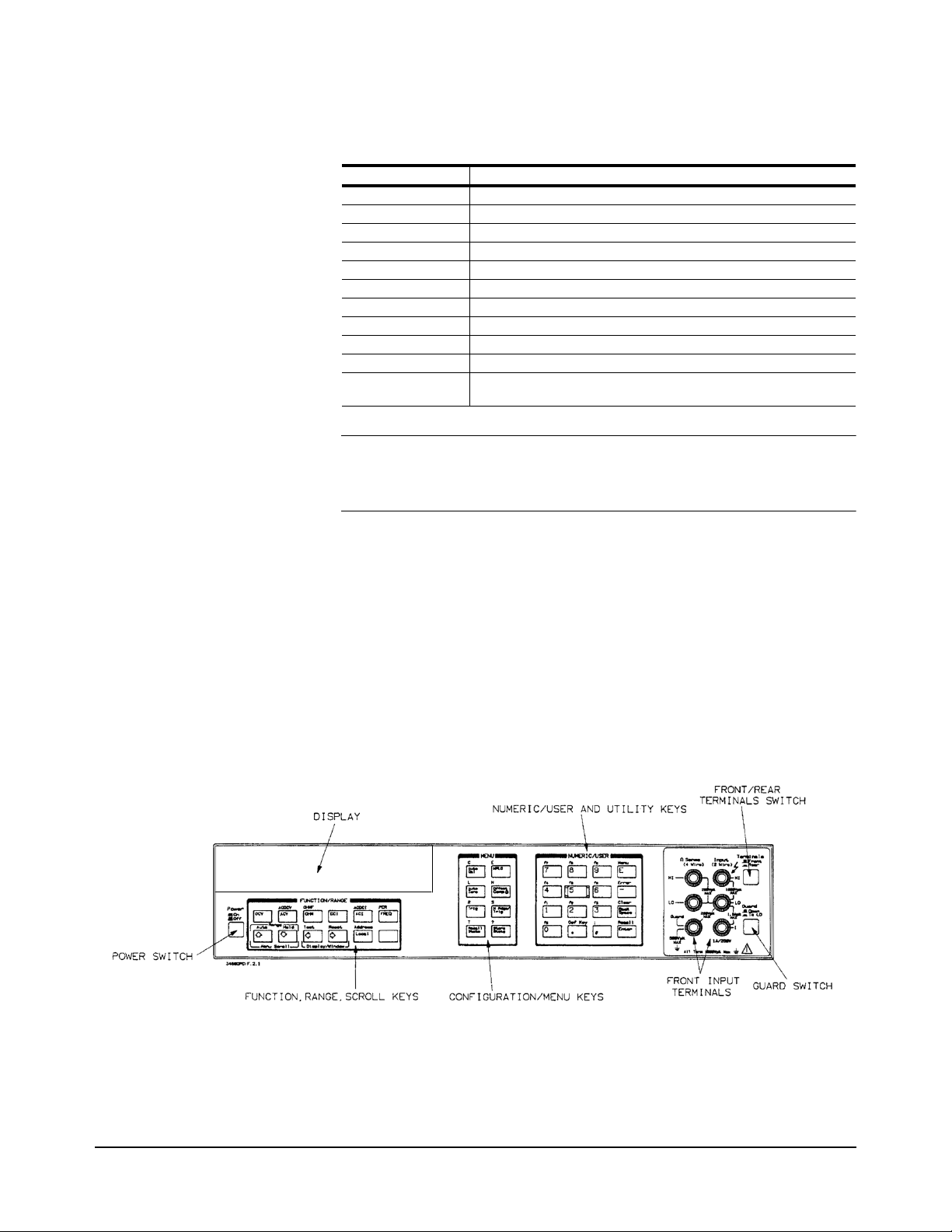
Table 3. Display Annunciators
Display Annunciator Description
SMPL Flashes whenever a reading is completed
REM The multimeter is in the GPIB remote mode
SRQ The multimeter has generated a GPIB service request
TALK The multimeter is addressed to talk on GPIB
LSTN The multimeter is addressed to listen on GPIB
AZERO OFF Autozero is disabled
MRNG Autorange is disabled (the multimeter is using a fixed range)
MATH One or two real-time or post-process math operations enabled
ERR An error has been detected
SHIFT The shift key has been pressed
MOREINFO More information concerning the present configuration is available
(use the right arrow key to view the information)
Note If the ERR annunciator is illuminated at this point, an error was detected
during or after the power-on self-test. You will learn how to determine the
error later in this chapter in “Reading the Error Register”.
Operating from the Front Panel
This section shows you how to make a simple DC voltage measurement, how
to use the various front panel keys, and describes the multimeter functions
important to front panel operation. Figure 3 shows the multimeter's front
panel features.
Figure 3. Front Panel
14 Chapter 2 Operating Information
Page 15
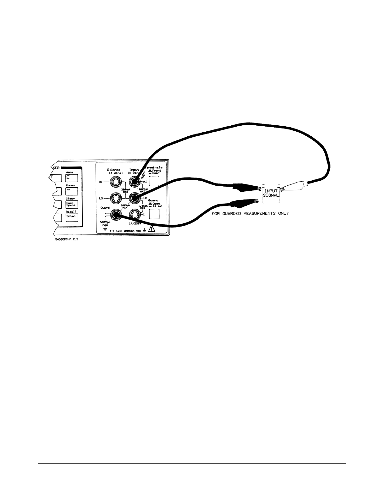
Making a
Measurement
In the power-on state, DC voltage measurements are selected and the
multimeter automatically triggers and selects the range. In the power-on
state, you can make DC voltage measurements simply by connecting a DC
voltage to the input terminals as shown in Figure 4. The connections shown
in Figure 4 also apply for AC voltage, 2-wire resistance, AC+DC voltage,
digitizing, and frequency or period measurements from a voltage input
source. Refer to Chapter 3 for a CAUTlON concerning the multimeter's
maximum input voltage and current.
Figure 4. Standard 2-wire (plus guard) measurements
Changing the
Measurement
Function
The row of keys located directly under the display (FUNCTION keys) select
the multimeter's standard measurement functions. Table 4 shows the
FUNCTION keys and the measurement function selected by each.
Chapter 2 Operating Information 15
Page 16
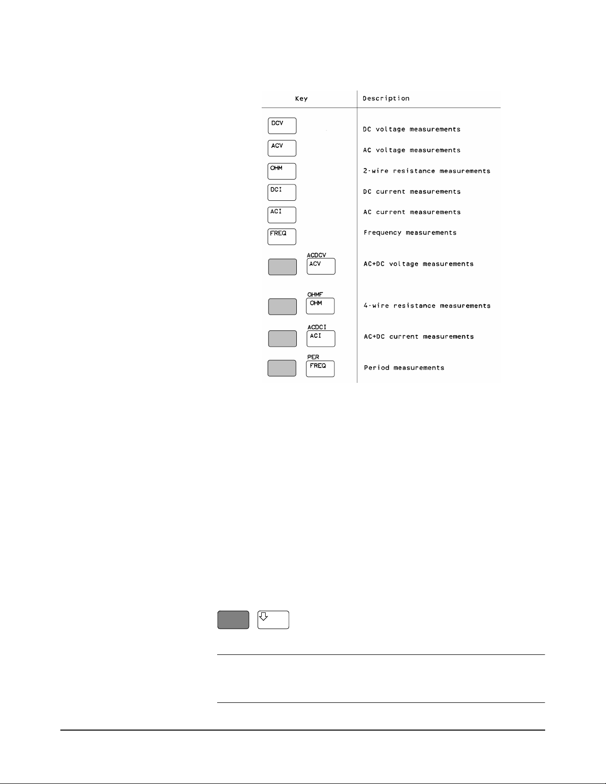
Table 4. Function Keys
Autorange and
Manual Ranging
Hold This choice allows you to shut off autoranging. To do this, let autorange
Note When you press the blue shift key, the display’s SHIFT annunicator
In addition to the functions selected by the FUNCTION keys, the multimeter
can perform direct-sampled or sub-sampled digitizing, ratio measurements,
and AC or AC+DC voltage measurements using the synchronous or random
measurement methods. These functions can be selected from the front panel
by accessing the appropriate command(s) using the alphabetic menu keys
(these keys are discussed later in this section under "Using the MENU
Keys").
In the power-on state, the multimeter automatically selects the appropriate
measurement range. This is called autorange. In many cases, you will
probably want to continue using autorange. However, you have two other
ranging choices: hold and manual ranging.
choose a range and then
Press:
Hold
illuminates. The shifted keyboard functions are printed in blue above the
keys.
16 Chapter 2 Operating Information
Page 17

Notice the display's MRNG (manual range) annunciator is on. This
annunciator is on whenever you are not using autorange.
Manual Ranging The second choice lets you manually select the range. When the multimeter
is in the measurement mode (that is, the multimeter is making and displaying
measurements or the display is showing OVLD) you can change the range
by pressing the up or down arrow keys. To go to a higher range.
Press:
By repeatedly pressing the up arrow key, you can increment up to the highest
range. When you reach the highest range, pressing the up arrow key no longer
changes the range. To go to a lower range.
Press:
By repeatedly pressing the down arrow key, you can decrement down to the
lowest range. When you reach the lowest range, pressing the down arrow key
no longer changes the range. To return to autoranging.
Press:
Auto
Self-Test When you applied power to the multimeter, it automatically performed a
limited power-on self-test. Before you start making measurements, however,
you may want to have more confidence that the multimeter is fully
operational. This is the job of the self-test. The self-test performs a series of
tests that check the multimeter's operability and accuracy.
Note Always disconnect any input signals before you run self-test. If you leave
an input signal connected to the multimeter, it cause a self-test failure.
The self-test takes over 50 seconds. To run self-test.
Press:
Test
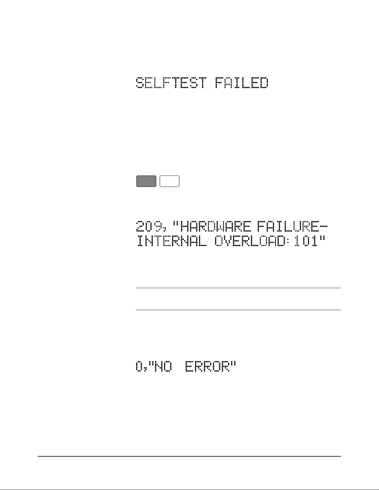
If the self-test passed, the display shows:
When self-test passes, you have a high confidence that the multimeter is
operational and, assuming proper calibration and autocalibration, that
Chapter 2 Operating Information 17
Page 18
measurements will be accurate.
If any of the tests failed, the ERR annunciator illuminates and the display
shows:
If the self-test failed, one or more error conditions have been detected. Refer
to the next section "Reading the Error Register".
Reading the Error
Register
Note When you get a hardware error (200-series prefix), run the self-test again. If
Whenever the display's ERR annunciator is illuminated, one or more errors
have been detected. A record of hardware errors is stored in the auxiliary
error register. A record of programming and syntax errors is stored in the
error register. To read the error record(s).
Press:
Error
_
The lowest numbered error and a description of the error is displayed. For
example, a possible error message is:
Use the right arrow key to view the entire message. When the error message
has a 100-series numeric prefix (e.g., 105), it indicates a programming or
syntax error. A 200-series prefix (e.g., 209) indicates a hardware error.
you repeatedly get the error, the multimeter may need repair.
If the ERR annunciator is still illuminated, more errors have been recorded.
Repeat the above key sequence until all errors have been read and the ERR
annunciator is no longer illuminated. When you have read all the errors, the
error annunciator goes off. If you try to read another error, the display shows:
You do not have to run self-test to get an error. The multimeter detects errors
that occur while entering data, when changing functions or ranges, and so
on. The multimeter beeps whenever it detects an error.
Whenever you want to clear information (such as an error description) from
the display and return it to displaying measurements.
Press:
18 Chapter 2 Operating Information
Page 19

Clear
Back
Space
Note You can also clear the display by repeatedly pressing the Back Space key
(unshifted).
Resetting the
Multimeter
Many times during operation, you may wish to return to the power-on state.
The front panel Reset key returns you to the power-on state without having
to cycle the multimeter's power. To reset the multimeter.
Press:
Reset
The multimeter begins the reset process with a display test which illuminates
all display elements including the annunciators as shown in Figure 5. (By
holding down the Reset key, the multimeter continuously performs its
display test).
Figure 5. Display Test
Caution Pressing the shifted front panel Reset key performs the
Using the
Configuration Keys
power-on sequence which has the same effect as cycling the
multimeter’s power. This destroys any stored reading and
compressed subprograms, sets the power-on SRQ bit in the
status register (these functions are discussed later in this
manual), resets the A/D converter reference frequency and
performs the power-on self test. Executing the RESET
command from the alphabetic command menu (MENU keys)
returns the mulitmeter to the power-on state but does not
perform the power-on sequence. The MENU keys are discussed
later in this chapter.
The configuration keys (unshifted MENU keys) let you rapidly access the
most frequently used multimeter features. Table 5 shows each key, the
corresponding multimeter command, and the function of each. (These
Chapter 2 Operating Information 19
Page 20

functions are discussed in detail in Chapters 3 and 4.)
Table 5. Configuration Key Functions
We will use the Trig key to demonstrate how to use the configuration keys.
Press:
Trig
The display shows:
This is the command header for the trigger command. Notice the multimeter
automatically placed a space after the command header.
Selecting a Parameter For parameters that have a list of choices (non-numeric parameters), you can
use the up and down arrow keys to review the choices.
Press:
20 Chapter 2 Operating Information
Page 21

The display shows:
Press:
The display shows:
When using the up or down arrow keys, if you step past the last parameter
choice, a wraparound occurs to the other end of the menu. Suppose you want
to suspend triggering. Press the up or down arrow key until the display shows:
Press:
Enter
You have now changed the trigger event from auto (power-on state) to HOLD
which causes the multimeter to stop taking readings. (Triggering is discussed
in detail in Chapter 4.)
Default Values Most parameters have a default value. A default value is the value selected
when you execute a command but do not specify a value. For example, the
default value for the trigger parameter is SGL.
Press:
Trig
Press:
Enter
Notice that the multimeter takes one reading and then stops (after the single
trigger, the trigger event becomes HOLD regardless of the previously
specified trigger event). You can also enter-1 to select the default value.
Press:
Enter
_
1
Enter
Chapter 2 Operating Information 21
Page 22

The multimeter again takes a single reading and then stops.
Numeric Parameters Some commands use numeric parameters. A numeric parameter is the actual
value used by the multimeter. We will use the NPLC configuration key to
demonstrate numeric parameters.
Press:
NPLC
This display shows:
Notice that if you press the up or down arrow key, no parameter choice is
displayed. This means there is no menu and you must enter a number. For
example.
Press:
1
Enter
You have now selected 1 power line cycle of integration time for the A/D
converter. Integration time is the actual time that the A/D converter measures
the input signal. (Integration time is discussed in detail in Chapter 3.)
Exponential Parameters You can also enter numeric parameters using exponential notation. For
example.
Press:
NPLC
1
0
0
E
_
3
Enter
You have now selected 0.1 power line cycles of integration time. At this
point, you should reset the multimeter to return the number of power line
cycles to 10 by pressing:
Reset
Multiple Parameters Many commands have more than one parameter. (Multiple parameters are
separated by commas.) We will use the NRDGS command, which has two
parameters, as an example of a command with multiple parameters.
Press:
N Rdge/
Trig
The display shows:
22 Chapter 2 Operating Information
Page 23

The first parameter in the NRDGS command is a numeric parameter that
specifies the number of readings made per trigger event. For example, to
specify 5 readings per trigger event.
Press:
5
The display shows:
The second parameter of the NRDGS command specifies the event that
initiates each reading. Since this is not a numeric parameter, a menu is
available for this parameter. Use the up or down arrow keys to cycle through
the list of choices. When the display shows:
Execute the command by pressing:
Enter
You have now selected five readings per trigger event. If you execute the
TRIG SGL command, for example, the multimeter will take five readings
and then stop. (The NRDGS command is discussed in detail in Chapter 4.)
Using the MENU Keys In addition to the configuration keys, the multimeter has an alphabetic
command menu that can be accessed using the shifted MENU keys labeled
C, E, L, N, R, S, and T. Each of these letters corresponds to the area you
will enter into the command menu. For example, to enter the menu with
commands starting with T.
Press:
T
Recall
State
The display shows:
You can now use the Menu Scroll keys (up or down arrow keys} to step
through the menu in alphabetical order (down arrow key) or in reverse
alphabetical order (up arrow key). For example, starting with the TARM
display shown above, by pressing the down arrow key once, the display
shows the next command in alphabetical order (TBUFF). (You can also press
and hold the up or down arrow key to rapidly step through the menu.) Once
you have found the desired command, you can press the Enter key to execute
it immediately (using default parameter values if applicable). If you need to
specify command parameter(s), with the command displayed, press the right
Chapter 2 Operating Information 23
Page 24

arrow key or the comma key (or, if the first parameter is numeric, a numeric
key). This selects the command and allows you to specify or select
parameter(s) using the procedures described earlier in this section.
There are two alphabetic menus available: FULL and SHORT. You can
select between these menus using the shifted Menu key. The specified menu
choice is stored in continuous memory (not lost when power is removed).
The FULL menu contains all commands except query commands that can
be constructed by appending a question mark to a command (e.g., BEEP,
BEEP?). (Query commands are discussed next.) The SHORT menu
eliminates the GPIB bus-related commands, commands that are seldom used
from the front panel, and any commands that have dedicated front panel keys
(e.g., the NPLC key or the Trig key).
Query Commands There are a number of commands in the alphabetic command directory that
end with a question mark. These commands are called query commands since
each returns a response to a particular question. For example, access the
LINE? query command from the command menu and press the Enter key.
The multimeter responds to this query command by measuring and
displaying the power line frequency. (Use the right arrow key to view the
entire response.) As another example, access the TEMP? command from the
command menu and press Enter. This command returns the multimeter's
internal temperature in degrees Centigrade.
Standard Queries The FULL command menu contains the following standard query
commands:
AUXERR? MCOUNT?
CAL? MSIZE?
CALNUM? OPT?
ERR? REV?
ERRSTR? SSPARM?
ID? STB?
ISCALE? TEMP?
LINE?
Additional Queries In addition to the queries listed above, you can create others by appending a
question mark to any command that can be used to program the multimeter.
For example, the AZERO command (Auto Zero configuration key) enables
or disables the autozero function. You can determine the present autozero
mode by appending a question mark to the AZERO command. To do this,
Press:
?
Auto
Zero
The multimeter responds by displaying the present autozero mode (power-on
mode = ON). (Notice that this command is immediately executed; you do
not have to press the Enter key.)
Store
State
Note The QFORMAT command can be used to specify whether query responses
24 Chapter 2 Operating Information
Page 25

will be numeric, alpha, or a combination of alpha and numeric. Refer to the
QFORMAT command, in Chapter 6, for more information.
Display Control The shifted Clear key, the Back Space key, and the Display/Window keys
(left and right arrow keys) allow you to control the display.
Clearing the Display Whenever you want to clear information (such as a query response) from the
display.
Press:
Clear
Back
Space
Display Editing The Back Space key allows you to edit parts of a command string while
entering the string or when the string is recalled (discussed later), For alpha
parameters or command headers, pressing the Back Space key once erases
the entire parameter or header. For commas, spaces, and numeric parameters,
only one character is erased each time you press Back Space. For example,
Press:
N Rdge/
Trig
1
0
The display shows:
By pressing the Back Space key once, the entire second parameter (LINE)
is erased. The display shows:
Now by pressing Back Space once, the comma is erased. Pressing Back
Space two more times erases both numeric characters (10). At this point, you
can reenter the first parameter using the numeric keypad and the second
parameter using the Menu Scroll keys. Press the Enter key to execute the
edited command.
Viewing Long Displays When entering commands containing more than 16 characters, the previously
entered characters are scrolled off the left side of the display to make room
for those being entered. The Display/Window keys (left and right arrow
keys) allow you to view the entire line by scrolling it left or right. The
Display/Window keys can also be used to view long strings such as error
messages, the calibration string (CALSTR? command), and user-defined key
definitions (discussed later). For example.
Press:
N Rgds/
Trig
100000
Chapter 2 Operating Information 25
Page 26

The display shows:
By pressing the left arrow key, you can view the first part of the command
while scrolling the last part off the right side of the display. Now, by pressing
the right arrow key, you can view the last part of the command and scroll the
first part off the left side of the display.
Note Think of the display as a window you can move to the left or right using the
arrow keys.
MORE INFO Display In addition to scrolling the display left and right, the Display/Window keys
allow you to view additional display information when the display's MORE
INFO annunciator is illuminated. For example, access and execute the
SETACV RNDM command from the alphabetic command menu. Now press
the front panel ACV key. Notice that the multimeter's MORE INFO
annunciator is illuminated. This means there is more information available
than is being displayed.
Press:
The present AC voltage measurement method (SETACV RNDM) is
displayed. At this point, reset the multimeter to return it to the power-on state
by pressing:
Reset
Digits Displayed When the multimeter is displaying readings, you can vary the number of
digits it displays. In the power-on state, the display is showing 7.5 digits
although the multimeter is resolving 8.5 digits. To display all 8.5 digits.
Press:
N
Offset
Comp 9
8
Note The display’s leftmost digit (referred to as a 1/2 digit) is implied when you
are specifying display digits.
The NDlG command only masks digits from the display. It does not affect
readings sent to reading memory or transferred over the GPIB bus. Also, you
cannot view more digits than are being resolved by the multimeter.
Enter
26 Chapter 2 Operating Information
Page 27

Recall You can easily recall the last executed command without repeating the
command entry process.
Press:
The display will show the last command executed. (You cannot recall
commands that are executed immediately such as Reset or DCV, or any
command that contained the calibration security code.) By repeating the
above keystrokes, you can recall previously executed commands. After
recalling the desired command, you can modify it (see "Display Editing"
earlier in this section) and execute it by pressing Enter.
Operating from Remote
This section shows you the fundamentals of operating the multimeter from
remote. This includes reading and changing the GPIB address, sending a
command to the multimeter, and retrieving data from the multimeter.
Recall
Enter
Input/Output
Statements
Reading the GPIB
Address
The statements used to operate the multimeter from remote depend on the
computer and its language. In particular, you need to know the statements
the computer uses to input and output information. For example, the input
statements for the Hewlett-Packard Series 200/300 BASIC language are:
ENTER or TRANSFER
The output statement is:
OUTPUT
Read your computer manuals to find out which statements you need to use.
The examples in this manual use Hewlett-Packard Series 200/300 BASIC
language.
Before you can operate the multimeter from remote, you need to know its
GPIB address (factory setting = 22). To check the address.
Press:
Address
Local
A typical display is:
The displayed response is the device address. When sending a remote
command, you append this address to the GPIB interface's select code
(normally 7). For example, if the select code is 7 and the device address is
22, the combination is 722.
Chapter 2 Operating Information 27
Page 28

Changing the GPIB
Address
Every device on the GPIB bus must have a unique address. If you need to
change the multimeter's address, access the ADDRESS command from the
command menu (MENU keys), with the display showing:
You can enter the new address. For example.
Press:
Sending a Remote
Command
Getting Data from the
Multimeter
1
You have now changed the address to 15. If you want to change the address
back to 22, repeat the above procedure (or use the Recall key) and specify
22 instead of 15.
To send the multimeter a remote command, combine the computer's output
statement with the GPIB select code, the device address, and finally, the
multimeter command. For example, to make the multimeter beep, send:
OUTPUT 722; "BEEP"
Notice the display's REM and LSTN annunciators are illuminated. This
means the multimeter is in the remote mode and has been addressed to listen
(receive a command).
The multimeter is capable of outputting readings and responses to query
commands. As an example, have the multimeter generate a response to a
query command by sending:
OUTPUT 722;"ID?"
When you send a query from remote, the multimeter does not display the
response as it did when you executed the command from its front panel.
Instead, the multimeter sends the response to its output buffer. The output
buffer is a register that holds a query response or a single reading until it is
read by the computer or replaced by new information. Use the computer's
input statement to get the response from the output buffer. For example, the
following program reads the response (3458A) and prints it.
5
Enter
10 ENTER 722;A$
20 PRINT A$
30 END
The same technique allows you to get readings from the multimeter.
Whenever the multimeter is making measurements and you have not enabled
reading memory (reading memory is discussed in Chapter 4), you can get a
reading by running the following program.
10 ENTER 722;A
20 PRINT A
30 END
28 Chapter 2 Operating Information
Page 29

The Local Key When you press a key on the multimeter's keyboard while operating from
remote, the multimeter does not respond. This is because the multimeter is
in the remote mode (as indicated by the display's REM annunciator) and is
ignoring all but the Local key. To return the multimeter to local mode.
Press:
Local
Chapter 2 Operating Information 29
Page 30

30 Chapter 2 Operating Information
Page 31

Chapter 3 Disassembly/Assembly
Procedures and Parts List
Introduction
This section contains the 3458A Covers and Printed Circuit Assemblies
Disassembly/Assembly procedures. Also included is the 3458A Parts Lists
and listings of printed circuit board assemblies.
WARNING Only personnel with knowledge of electronic circuitry and an
awareness with the hazards involved should remove and install
any printed circuit board assemblies.
Caution To prevent equipment circuit damage, always remove the ac
line power cord before removing or replacing any assembly. To
prevent electrostatic discharge (ESD) damage to ICs, always
observe anti-static techniques when assemblies are handled or
serviced.
Static Handling
Static electricity is a familiar phenomenon which, except for an occasional
shock, doesn't seem very serious. However, it has been proven that in the
electronics industry electrostatic discharge (ESD) is a major cause of
component failure. In many cases, the component damaged may not
immediately fail, causing low instrument reliability and future repairs. ESD
damage can occur at static levels below human perception. It has also been
shown that ESD can affect both passive and active devices.
The following guidelines are the minimum requirements for a static safe
service environment.
• The workbench should be equipped with a conductive table mat. The
mat should be grounded to earth ground through a 1 M ohm resistor.
The mat should be equipped with at least one swivel connector for
connecting wrist straps.
• All service and handling personnel should wear a conductive wrist strap
in contact with bare skin. This strap should be connected to the swivel
connector on the conductive table mat through a 1 M ohm resistor.
• All metal equipment at a workstation must be grounded. This includes
soldering irons, solder removers, shelving, and equipment stands.
Chapter 3 Disassembly/Assembly Procedures and Parts List 31
Page 32

Clean Handling
• Only one common ground should be provided at the workstation.
• The workstation should be kept free of nonconductors. No common
plastics, polybags, cardboard, cigarette or candy wrappers should be
allowed. There should not be rugs or carpet on the floor, shelving, or
bench top.
• Only proper containers should be used for shipping, storing or
transporting assemblies. This is required on any assembly shipped to
Agilent Technologies for repair or replacement.
Due to the accuracy of the 3458A, use the following clean handling
techniques when removing/installing printed circuit board assemblies.
• Handle the assemblies only by their edges.
• Be sure to place them on a clean workbench away from dirty or dusty
conditions.
Printed Circuit Assembly Identification
The printed circuit assemblies within the 3458A Multimeter are identified
by the part number of the printed circuit board and the engineering revision
code (ERC). These two sequences of numbers are used to exactly identify
the electrical characteristics of the printed circuit board. In any
correspondence concerning a particular printed circuit board, it is important
to accurately identify the board configuration. This is done by using the
board part number, followed by the engineering revision code (ERC) on the
board. For example:
03458-66505-2825
would identify a particular printed circuit board in the 3458A. The board
part number is 03458-66505 and the ERC is 2825.
Board Part Number The Agilent Technologies part number of a printed circuit board is etched
on the board. This is a ten-digit number, separated by a hyphen into two
groups of five digits. The first five digits identify the model number or
accessory number of which the printed circuit board is a part. The last five
digits are a unique part number identifying the printed circuit board.
Engineering Revision
Code
On the Engineering Revision Code (ERC) label, the four-digit code is in the
form of YYWW, where YY represents the last two digits of the year minus
60 and WW is the week code. For example, an Engineering Revision Code
of 2825 would identify a change made in the 25th week of 1988.
The ERC number is updated whenever a change is made to the assembly.
This change may be a printed circuit board revision, a component change, or
32 Chapter 3 Disassembly/Assembly Procedures and Parts List
Page 33

NOTE
The label numbers
in Figures 5 to 10
show the order of
cover removal. Use
reverse order for
installation.
a revised test and assembly procedure. The ERC should be checked against
schematics, component locator diagrams, and parts lists to ensure
compatibility. ERCs with values lower than those noted on the schematics,
component locator diagrams, and parts lists are described in a backdating
section. ERCs with a value higher that those noted will be covered by a
manual change sheet, manual update, or manual revisions.
Figure 6. Right Side Handle Removal/Installation
Covers Removal/Installation Procedures
The following procedures show how to remove the top/bottom covers and
shields on the 3458A. Removal of the covers and shields are required to
replace the printed circuit board assemblies.
Tools Required You need:
1. #1 Pozidriv screwdriver
2. #TX15 Torx driver
3. #TX10 Torx driver
Covers Removal
Procedure
Do the following:
1. Remove all connections to the 3458A.
2. Remove ac power from the 3458A.
3. Refer to Figure 6. Turn the instrument so its right side (as seen from
the front) faces you.
4. Use the #1 Pozidriv to remove the right side handle strap screws.
Then remove the strap.
Chapter 3 Disassembly/Assembly Procedures and Parts List 33
Page 34

5. Refer to Figure 7. Turn the instrument so its left side faces you.
Figure 7. Remove/Install Left Side Handle
6. Use the #1 Pozidriv to remove the left side handle strap screws. Then
remove the strap.
7. Refer to Figure 8. Use the #TX10 Torx driver to remove both or either
the top and bottom cover ground screws, depending on which cover is
to be removed.
8. Refer to Figure 9. Turn the instrument so its rear faces you.
9. Use the #TX15 Torx driver to remove the four rear bezel screws.
Then remove the rear bezel.
10. If you do not wish to remove the top cover, continue with step 12.
11. To remove the top cover, pull the cover toward the rear until it clears
the front panel. Then slide it forward and away from the instrument.
12. If you do not wish to remove the bottom cover, continue with step 14.
13. Turn the 3458A over so its top sits on your workbench. To remove the
bottom cover, pull the cover toward the rear until it clears the front
panel. Then slide it forward and away from the instrument. Leave the
instrument in its present position.
14. If you do not wish to remove the bottom shield, continue with step 16.
15. Refer to Figure 10. Use the #TX10 Torx driver to remove the bottom
shield screw. Then remove the shield. Pull the shield toward the rear
of the instrument until the shield retainers line up with the slots in the
shield. Lift the shield off.
34 Chapter 3 Disassembly/Assembly Procedures and Parts List
Page 35

16. If you do not wish to remove the top shield, continue with step 19.
Figure 8. Remove/Install Cover Ground Screws
Figure 9. Remove/Install Rear Bezel
Chapter 3 Disassembly/Assembly Procedures and Parts List 35
Page 36

Figure 10. Remove/Install Bottom Shield Screw
17. Refer to Figure 11. Turn the instrument over so its bottom sits on your
workbench.
18. Use the #TX10 Torx driver to remove the top shield screw. Then
remove the shield. Pull the shield toward the rear of the instrument
until the shield retainers line up with the slots in the shield. Lift the
shield off.
19. Refer to the appropriate procedures in this section to remove the
printed circuit board assembly.
Covers Installation
Procedure
36 Chapter 3 Disassembly/Assembly Procedures and Parts List
Do the following:
1. Remove all connections to the 3458A.
2. If installing the top shield is not required, continue with step 6.
3. Refer to Figure 11. Turn the instrument over so its bottom sits on your
workbench.
4. Line up the slots on the top shield with the shield retainers. Then push
the shield toward the front of the instrument until the shield screw hole
Page 37

lines up with the hole in the chassis. Use the #TX10 Torx driver to
reinstall the shield screw.
5. If installing the bottom shield is not required, continue with step 9.
6. Refer to Figure 10. Turn the instrument over so its top sits on your
workbench.
Figure 11. Remove/Install Top Shield Screw
7. Remove ac power from the 3458A.
8. Line up the slots on the bottom shield with the shield retainers. Then
push the shield toward the front of the instrument until the shield
screw hole lines up with the screw hole in the chassis. Use the #TX10
Torx driver to reinstall the shield screw.
9. If installing the bottom cover is not required, continue with step 11.
10. Install the bottom cover by placing it over the chassis with the front of
the cover just clearing the front panel. Then push the cover toward the
front of the instrument into the front panel bezel.
11. If installing the top cover is not required, continue with step 14.
Chapter 3 Disassembly/Assembly Procedures and Parts List 37
Page 38

12. Turn the 3458A over so the bottom sits on your workbench.
13. Install the top cover by placing it over the chassis with the front of the
cover just clearing the front panel. Then push the cover toward the
front of the instrument into the front panel bezel.
14. Refer to Figure 9. Turn the instrument so its rear faces you.
15. Reinstall the rear bezel. Use the #TX15 Torx driver to reinstall the
four rear bezel screws.
16. Refer to Figure 8. Turn the instrument so its left side faces you. Use
the #TX10 Torx driver to reinstall the top and/or bottom cover ground
screws.
WARNING For safety purposes and proper operation, it is imperative that
the cover grounding screws be reinstalled.
17. Refer to Figure 7. Reinstall the left side handle strap. Use the
#1 Pozidriv to reinstall the side handle strap screws.
18. Refer to Figure 6. Turn the instrument so its right side faces you.
19. Reinstall the right side handle strap. Use the #1 Pozidriv to reinstall
side handle strap screws.
20. Your instrument is now ready for use. Agilent Technologies suggests
that after you apply power that you perform an automatic calibration
on the instrument. To do this, use the "ACAL ALL" command.
38 Chapter 3 Disassembly/Assembly Procedures and Parts List
Page 39

Assemblies Removal/Installation Procedures
Table 6 lists all 3458A printed circuit board assemblies and assembly
locations in the instrument. The assembly locations are also shown in
Figure 12 and Figure 13.
Table 6. 3458A Assemblies Locations
Ref Desig Part Number Assembly
A1 03458-66501 DC Circuitry Inguard/Top
A2 03458-66502 AC Circuitry Inguard/Bottom
A3 03458-66503 A/D Converter and
A4 03458-66504 Inguard Power
A5 03458-66505 Outguard Controller Outguard/Top
A5 03458-66515 Outguard Controller
A6 03458-66506 Outguard Power
A7 03458-66507 Display Logic Front Panel
A9 03458-66509 DC Reference Inguard/Top
A9 03458-66519 DC Reference
A10 03458-66510 Front/Rear Switch Inguard/Top
Tools Required You need:
1. #1 Pozidriv screwdriver
Description
Location in Instrument
Inguard/Bottom
Inguard Logic
Inguard/Bottom
Supply
Outguard/Top
(Opt 001)
Outguard/Bottom
Supply
Inguard/Top
(Opt 002)
2. #TX15 Torx driver
3. #TX10 Torx driver
4. 7 millimeter nut driver (for Outguard Controller assembly only)
5. Small flat bladed screwdriver (for Display Logic assembly only)
6. Large screwdriver (e.g., #2 Pozidriv; for Display Logic assembly
only)
Chapter 3 Disassembly/Assembly Procedures and Parts List 39
Page 40

DC Circuitry
Assembly
Removal/Installation
Procedures
The following procedures show how to remove and install the DC Circuitry
Printed Circuit Board Assembly.
Figure 12. Assembly Locations (Top of Instrument)
40 Chapter 3 Disassembly/Assembly Procedures and Parts List
Page 41

Figure 13. Assembly Locations (Bottom of Instrument)
Refer to Figure 14 for the following procedures.
Removal Procedure 1. Use the Covers Removal Procedure in this section of the manual to
remove the 3458A top cover and top shield. It is not necessary to
remove the bottom cover and bottom shield.
Chapter 3 Disassembly/Assembly Procedures and Parts List 41
Page 42

2. Set the 3458A on your workbench with the top facing you.
3. Unplug the following wires and cables. Unless otherwise noted, all
wires and cables are unplugged from the DC Circuitry assembly.
a. Blue wire from the metal inguard shield. This wire is not plugged
into the DC Circuitry assembly, but must be unplugged to remove
the assembly. Move the wire out of the way.
b. Grey wire from the metal inguard circuit ground. This wire is not
plugged into the DC Circuitry assembly, but must be unplugged to
remove the assembly. Move the wire out of the way.
c. Yellow wire from P202. Move the wire out of the way.
d. Orange wire from P7. Move the wire out of the way.
e. Grey wire from P6. Move the wire out of the way.
f. Black and white wires from P8 and P9, respectively. The black and
white wires form a white cable. Move the cable out of the way.
g. Grey 20 pin cable from P3. Move the cable out of the way.
4. Use the #TX 10 Torx driver to remove the two screws from the
DC Reference assembly.
5. Use the #TX10 Torx driver to remove the eight screws from the
DC Circuitry assembly.
6. Use the plastic board extractor on the DC Circuitry board to unplug
the board from the inguard chassis. Then completely remove the
board.
Installation Procedure 1. Line up the DC Circuitry board with the connector in the inguard
chassis. Plug the board into the connector.
2. Use the #TX10 Torx driver to install the eight screws on the
DC Circuitry assembly.
3. Use the #TX10 Torx driver to install the two screws on the
DC Reference assembly.
4. Plug in the following wires and cables:
a. Locate the blue wire connected to the power transformer. Plug the
wire into the metal inguard shield.
b. Locate the grey wire connected to the power transformer. Plug the
wire into the metal inguard circuit ground.
42 Chapter 3 Disassembly/Assembly Procedures and Parts List
Page 43

Figure 14. DC Circuitry Assembly Removal/Installation
c. Locate the yellow wire connected to the Front/Rear Switch
assembly. Plug it into P202 on the DC Circuitry assembly.
d. Locate the orange wire connected to the Front/Rear Switch
assembly. Plug it into P7 on the DC Circuitry assembly.
Chapter 3 Disassembly/Assembly Procedures and Parts List 43
Page 44

e. Locate the grey wire connected to the Front/Rear Switch assembly.
Plug it into P6 on the DC Circuitry assembly.
f. Locate the white cable with the white and black wires connected to
the Front/Rear Switch assembly. Plug the white and black wires
into P8 and P9, respectively. P8 and P9 are on the DC Circuitry
assembly.
g. Locate the grey 20-pin cable connected to the A/D Converter and
Inguard Logic assembly. Line up the cable plug with socket P3 on
the DC Circuitry assembly. Then plug the cable all the way in.
5. Use the Covers Installation Procedure in this section of the manual to
install the 3458A top cover and top shield.
DC Reference
Assembly
Removal/Installation
The following procedures show how to remove and install the DC Reference
Printed Circuit Board Assembly.
Refer to Figure 14 for the following procedures.
Procedures
Removal Procedure 1. Use the Covers Removal Procedure in this section of the manual to
remove the 3458A top cover and top shield. It is not necessary to
remove the bottom cover and bottom shield.
2. Set the 3458A on your workbench with the top facing you.
3. Use the #TX10 Torx driver to remove the two screws from the
DC Reference assembly.
4. Unplug and remove the board from the DC Circuitry assembly.
Installation Procedure 1. A top and bottom cover needs to be installed over the reference device
located on the DC Reference assembly. To install the covers, place
one cover over the top of the device and another on the bottom side of
the DC Reference assembly printed circuit board. Use your fingers to
hold the covers in place. Then line up the screw holes in the covers
with the screw holes on the printed circuit board. The covers should
now completely enclose the reference device.
2. Line up the DC Reference board with the connectors on the
DC Circuitry assembly. Hold the covers over the reference device in
place while installing the DC Reference assembly. Then plug the
board all the way into the connectors.
3. Use the #TX10 Torx driver to install the two screws on the
DC Reference assembly.
4. Use the Covers Installation Procedure in this section of the manual to
install the 3458A top cover and top shield.
44 Chapter 3 Disassembly/Assembly Procedures and Parts List
Page 45

Figure 15. AC Converter Assembly Removal/Installation
AC Converter
Assembly
Removal/Installation
The following procedures show how to remove and install the AC Converter
Printed Circuit Board Assembly.
Refer to Figure 15 for the following procedures.
Procedures
Removal Procedure 1. Use the Covers Removal Procedure in this section of the manual to
remove the 3458A bottom cover and bottom shield. It is not necessary
to remove the top cover and top shield.
2. Set the 3458A on your workbench with the bottom facing you.
3. Unplug the grey 20-pin cable from the AC Converter assembly.
4. Unplug the black striped white wire from the metal inguard chassis.
Chapter 3 Disassembly/Assembly Procedures and Parts List 45
Page 46

5. For easier removal of the AC Converter assembly, you may wish to
unplug and lay aside both the blue and grey fiber optic cables
connecting the A/D Converter and Inguard Logic assembly to the
outguard.
6. Remove the pushrod from the Guard switch. You may need to pry the
pushrod loose with a small flat blade screwdriver. Then completely
remove it from the rear of the front panel.
7. Use the #TX10 Torx driver to remove the four screws from the
AC Converter assembly.
8. Unplug and remove the AC Converter board from the inguard chassis.
Installation Procedure 1. Line up the AC Converter board with the connector in the inguard
chassis. Then plug the board all the way into the connector.
2. Use the #TX 10 Torx driver to install the four screws on the
AC Converter assembly.
3. Locate the grey 20-pin cable connected to the Inguard Power Supply
assembly. Line up the cable plug with the socket on the
AC Converter assembly. Then plug the cable all the way in.
4. Plug the black striped white wire from the AC Converter into the
metal inguard chassis.
5. Plug in both the blue and grey fiber optic cables into the A/D
Converter and Inguard Logic assembly, if previously unplugged.
6. Guide the Guard switch pushrod through the rear of the front panel's
access hole. Then align the pushrod with the Guard switch shaft and
push it all the way onto the shaft.
7. Use the Covers Installation Procedure in this section of the manual to
install the 3458A bottom cover and bottom shield.
A/D Converter
Assembly
Removal/Installation
The following procedures show how to remove and install the A/D Converter
and Inguard Logic Printed Circuit Board Assembly.
Refer to Figure 16 for the following procedures.
Procedures
Removal Procedure 1. Use the Covers Removal Procedure in this section of the manual to
remove the 3458A bottom cover and bottom shield. It is not necessary
to remove the top cover and top shield.
2. Set the 3458A on your workbench with the bottom facing you.
3. Locate the grey 20-pin cable that connects the A/D Converter and
46 Chapter 3 Disassembly/Assembly Procedures and Parts List
Page 47

Inguard Logic assembly to the Inguard Power Supply assembly.
Unplug this cable at the A/D Converter and Inguard Logic assembly.
4. Locate the grey 20-pin cable that connects the A/D Converter and
Inguard Logic assembly to the DC Circuitry assembly. Unplug this
cable at the A/D Converter and Inguard Logic assembly.
5. Unplug both sets (four cables) of the blue and grey fiber optic cables
that connect the A/D Converter and Inguard Logic assembly to the
Outguard Power Supply assembly.
Figure 16. A/D Converter and Inguard Logic Assembly
6. Use the #TX10 Torx driver to remove the three screws on the shield
and the two screws on the A/D Converter and Inguard Logic assembly.
Then remove the shield.
7. Unplug and remove the A/D Converter and Inguard Logic board from
the inguard chassis.
Installation Procedure 1. Line up the A/D Converter and Inguard Logic board with the
Chapter 3 Disassembly/Assembly Procedures and Parts List 47
Page 48

NOTE
The label numbers in
Figures 16 and 17
show the order
assembly removal.
Use reverse order
for installation.
connector in the inguard chassis. Then plug the board all the way into
the connector.
2. Place the A/D Converter and Inguard Logic shield on the board. Then
use the #TX10 Torx driver to install the three screws on the shield.
3. Locate the grey 20-pin cable connected to the Inguard Power Supply
assembly. Line up the cable plug with the corresponding socket on the
A/D Converter and Inguard Logic assembly. Then plug the cable all
the way in.
Figure 17. Remove/Install Transformer Cable on Inguard Power Supply
4. Locate the grey 20-pin cable connected to the DC Circuitry assembly.
Line up the cable plug with the corresponding socket on the A/D
Converter and Inguard Logic assembly. Then plug the cable all the
way in.
5. Plug in both sets of the blue and grey fiber optic cables into the
corresponding sockets on the A/D Converter and Inguard Logic
assembly.
6. Use the Covers Installation Procedure in this section of the manual to
install the 3458A bottom cover and bottom shield.
48 Chapter 3 Disassembly/Assembly Procedures and Parts List
Page 49

Inguard Power
Supply Assembly
The following procedures show how to remove and install the Inguard Power
Supply Printed Circuit Board Assembly.
Removal/Installation
Procedures
Removal Procedure 1. Use the Covers Removal Procedure in this section of the manual to
remove the 3458A top/bottom covers and top/bottom shields.
2. Set the 3458A on your workbench with the top facing you.
3. Refer to Figure 17. Unplug the 5-wire cable from the Inguard Power
Supply assembly. This cable is connected to the power transformer.
4. Refer to Figure 18 for the rest of this procedure.
5. Set the 3458A on your workbench with the bottom facing you.
Figure 18. Inguard Power Supply Assembly Removal/Installation
6. Locate the grey 20-pin cable that connects between the A/C Converter
assembly and Inguard Power Supply assembly. Unplug the cable at
the power supply assembly.
7. Locate the grey 20-pin cable that connects between the A/D Converter
assembly and Inguard Power Supply assembly. Unplug the cable at
the power supply assembly, and Inguard Logic assembly.
8. Use the #TX 10 Torx driver to remove the three screws on the Inguard
Power Supply assembly.
9. Push the Inguard Power Supply assembly toward the left, of the
instrument (as seen from the front) until it clears the slot in the chassis.
Then remove the board from the instrument.
Chapter 3 Disassembly/Assembly Procedures and Parts List 49
Page 50

Installation Procedure 1. Set the 3458A on your workbench with the bottom facing you.
2. Refer to Figure 18. Line up the Inguard Power Supply assembly with
the slots in the chassis. Then push the board in.
3. Use the #TX10 Torx driver to install the three screws on the Inguard
Power Supply board.
4. Locate the grey 20-pin cable connected to the AC Converter assembly.
Line up the cable plug with the socket on the AC Converter assembly.
Then plug the cable all the way in.
5. Locate the grey 20-pin cable connected to the A/D Converter and
Inguard Logic assembly. Line up the cable plug with the socket on the
A/D Converter and Inguard Logic assembly. Then plug the cable all
the way in.
Figure 19. Outguard Controller Assembly Removal/Installation
6. Set the 3458A on your workbench with the top facing you.
7. Refer to Figure 17. Locate the cable connected to the power
transformer. Line up the cable plug with the socket on the Inguard
Power Supply assembly. Then plug the cable in.
8. Use the Covers Installation Procedure in this section of the manual to
install the 3458A top/bottom covers and top/bottom shields.
50 Chapter 3 Disassembly/Assembly Procedures and Parts List
Page 51

Outguard Controller
Assembly
Removal/Installation
The following procedures show how to remove and install the Outguard
Controller Printed Circuit Board Assembly.
Refer to Figure 19 for the following procedures.
Procedures
Removal Procedure 1. Use the Covers Removal Procedure in this section of the manual to
remove the 3458A top cover. It is not necessary to remove the bottom
covers and the top/bottom shields.
2. Set the 3458A on your workbench with the top facing you.
3. Use a 7-millimeter nut driver to remove the two hex standoffs on the
rear panel GPIB connector.
4. Locate the grey 20-pin cable that connects between the Outguard
Controller assembly and Outguard Power Supply assembly. Unplug
the cable at the controller assembly.
5. Use the #TX10 Torx driver to remove the three screws on the
Outguard Controller assembly.
6. Push the board toward the front of the instrument, as far it will go,
while the board is still laying down flat in the chassis.
7. Pull the outside edge of the board up. Do this until the inside edge of
the board can be removed from the slots in the instrument chassis.
Then pull the board completely out of the instrument.
Installation Procedure 1. Insert the Outguard Controller board into the slots in the chassis.
Make sure the board is as far as possible toward the front of the
instrument.
2. Place the rest of the board into the instrument until it lays down flat in
the chassis. Then slide the board toward the rear of the instrument.
3. Use the #TX10 Torx driver to install the three screws on the Outguard
Controller assembly.
4. Locate the grey 20-pin cable connected to the Outguard Power Supply
assembly. Line up the cable plug with the socket on the Outguard
Controller assembly. Then plug the cable in.
5. Use the 7-millimeter nut driver to install the two hex standoffs on the
rear panel GPIB connector.
6. Use the Covers Installation Procedure in this section of the manual to
install the 3458A top cover.
Chapter 3 Disassembly/Assembly Procedures and Parts List 51
Page 52

Outguard Power
Supply Assembly
Removal/Installation
The following procedures show how to remove and install the Outguard
Power Supply Printed Circuit Board Assembly.
Refer to Figure 20 for the following procedures.
Procedures
Removal Procedure 1. Use the Covers Removal Procedure in this section of the manual to
remove the 3458A bottom cover. It is not necessary to remove the top
cover and the top/bottom shields.
2. Set the 3458A on your workbench with the top facing you.
3. Pull the power switch pushrod off the ac power switch. You may need
to pry the pushrod loose with a small screwdriver. Then remove the
pushrod by pulling it out of the front panel from the rear.
4. Locate the grey 20-pin cable that connects the Outguard Power Supply
assembly to the Main Controller assembly. Unplug this cable at the
Outguard Power Supply assembly.
5. Locate the grey 26-pin cable that connects the Outguard Power Supply
assembly to the Display assembly. Unplug this cable at the Outguard
Power Supply assembly.
6. Locate the 8-pin cable that connects the Outguard Power Supply
assembly to the power transformer. Unplug the cable from the power
supply assembly. Move the cable so it lays on the outside of the
outguard chassis.
52 Chapter 3 Disassembly/Assembly Procedures and Parts List
Page 53

Figure 20. Outguard Power Supply Assembly Removal/Installation
7. Unplug the 4-pin cable from socket P301. This cable is connected to
Chapter 3 Disassembly/Assembly Procedures and Parts List 53
Page 54

the Ext Out and Ext Trig connectors on the rear panel. Move the cable
out of the way.
8. Unplug the 2-pin cable from socket P3. This cable is connected to the
fan. Move the cable out of the way.
9. Unplug the two black striped white wires from the AC power filter on
the rear panel. Move the wires out of the way.
10. Unplug both sets (four cables) of the blue and grey fiber optic cables
from the Outguard Power Supply Assembly. These cables connect the
A/D Converter and Inguard Logic assembly to the Outguard Power
Supply assembly. Move the cables out of the way.
11. Use the #TX10 Torx driver to remove the two screws on the power
supply regulator heat sink.
12. Use the #TX10 Torx driver to remove the two screws on the Outguard
Power Supply assembly.
13. Push the Outguard Power Supply board toward the front of the
instrument, as far it will go. Then lift it up and away from the
instrument.
Installation Procedure 1. Line up the slots on the Outguard Power Supply board with the sheet
metal hook tabs on the chassis. Make sure the board is as far as
possible toward the front of the instrument.
2. Place the board on top of the chassis. Then push it all the way to the
rear of the instrument.
3. Use the #TX10 Torx driver to install the two screws on the power
supply regulator heat sink.
4. Use the #TX10 Torx driver to install the two screws on the Outguard
Power Supply assembly.
5. Plug in both sets of the blue and grey fiber optic cables into the
corresponding sockets on the Outguard Power Supply assembly.
6. Locate the two black striped white wires. Connect the wire from
"LINE" to the left terminal (as seen from the instrument's front) of the
filter. Connect the "NEUTRAL" to the right terminal on the filter.
These connections are also shown on a drawing on the Outguard
Power Supply assembly. The drawing is located toward the rear of the
board near ac line select switches.
7. Locate the 2-pin cable connected to the fan. Plug the cable into socket
P3.
8. Locate the 4-pin cable connected to the Ext Out and Ext Trig
54 Chapter 3 Disassembly/Assembly Procedures and Parts List
Page 55

NOTE
The label numbers in
Figure 20 and 24
show the order of
assembly removal.
Use reverse order
for installation.
connectors on the rear panel. Plug the cable into socket P301.
9. Locate the 8-pin cable connected to the power transformer. Move the
cable so it lays on top of the Outguard Power Supply assembly. Then
plug the cable into socket P3.
10. Locate the grey 20-pin cable connected to the Outguard Controller
assembly. Line up the cable plug with the socket on the Outguard
Power Supply assembly. Then plug it all the way in.
11. Guide the power switch pushrod through the rear of the transformer
shield's access hole. Then guide the pushrod through the rear of the
front panel's access hole. Align the pushrod with the ac power switch
shaft and push it onto the shaft.
Figure 21. Guard and Power Pushrods, and Display Cable Locations
12. Use the Covers Installation Procedure in this section of the manual to
install the 3458A bottom cover.
Chapter 3 Disassembly/Assembly Procedures and Parts List 55
Page 56

Display Logic
Assembly
The following procedures show how to remove and install the Display Logic
Board Assembly.
Removal/Installation
Procedures
Removal Procedure 1. Use the Covers Removal Procedure in this section of the manual to
remove the 3458A top/bottom covers and top/bottom shields.
2. Set the 3458A on your workbench with the bottom facing you.
3. Refer to Figure 21. Do the following:
a. Locate and pull the power switch pushrod off the power switch.
You may need to pry the pushrod loose with a small screwdriver.
Then remove the pushrod by pulling it out of the front panel from
the rear.
Figure 22. Top Trim and Front/rear Pushrod Locations, and Unlock Panel
b. Locate the grey 26-pin cable that connects the Outguard Power
Supply assembly to the Display assembly. Unplug this cable at the
Outguard Power Supply assembly.
c. Locate and pull the Guard switch pushrod off the Guard switch.
You may need to pry the pushrod loose with a small screwdriver.
56 Chapter 3 Disassembly/Assembly Procedures and Parts List
Page 57

Then remove the pushrod by pulling it out of the front panel from
the rear.
4. Set the 3458A on your workbench with the top facing you.
5. Refer to Figure 22. Do the following:
a. Locate and pull the Front/Rear switch pushrod off the Front/Rear
Terminals switch. You may need to pry the pushrod loose with a
small screwdriver. Then remove the pushrod by pulling it out of
the front panel from the rear.
b. With a small flat bladed screwdriver, pry the top trim loose and
remove from the Front Panel assembly.
6. Set the 3458A on your workbench with the left side facing you.
7. Refer to Figure 23. Insert a large screwdriver between the Front Panel
assembly and the chassis, as shown in the figure. With the
screwdriver, carefully pry the left side of the Front Panel assembly
loose. Move the front panel out of the chassis until it unlocks from the
chassis. Do not move it any more, or it may break.
Figure 23. Remove Front Panel Assembly
8. Refer to Figure 22. With a small flat bladed screwdriver, lift up the
Front Panel assembly and unlock it from the chassis. Carefully move
some more of the Front Panel assembly's left side (as seen from the
front of the instrument) until free from the chassis. Then move the rest
of the Front Panel assembly out and away from the instrument as far as
it can go. Note that the assembly can only be moved a short distance,
since the front terminals are still internally connected to the
instrument.
Chapter 3 Disassembly/Assembly Procedures and Parts List 57
Page 58

9. Turn the instrument so the front panel faces you.
10. Locate and unscrew (rotate counterclockwise) the current terminal
binding post until it stops. Push in on the terminal and rotate it
clockwise. Then remove the current terminal/fuse assembly.
11. Refer to Figure 24. Use the #TX10 Torx driver to remove the two
Torx screws from the front terminals. Then use a #1 Pozidriv
screwdriver to remove the two Pozidriv screws from the front
terminals. This removes the front terminals from the Front Panel
assembly.
12. Completely remove the Front Panel assembly from the instrument.
13. Place the Front Panel assembly face down on a soft anti-static mat.
14. Refer to Figure 25. Use the #TX10 Torx driver to remove the single
Torx screw from the Display assembly.
15. Push the Display board toward the left (with input terminals at your
right side) as far as it can go. Then pull its bottom up and lift it out
from the Front Panel assembly.
Figure 24. Remove/Install Screws on Front Terminals
58 Chapter 3 Disassembly/Assembly Procedures and Parts List
Page 59

Figure 25. Remove/Install Display Screw
Installation Procedure 1. Align the slots in the Display assembly with the hook tabs on the Front
Panel assembly. Be sure the board is as close to the left side of the
Front Panel assembly as possible. Then push the board down until it
locks in place.
2. Push the board as far as possible toward the right side of the Front
Panel assembly.
3. Refer to Figure 25. Use the #TX10 Torx driver to install the screw on
the Display assembly.
4. Set the 3458A on your workbench with the right side facing you.
5. Carefully place the front terminals into the appropriate holes in the
front panel.
6. Refer to Figure 24. Use the #TX10 Torx driver to install the two Torx
screws on the front terminals. Then use a #1 Pozidriv screwdriver to
install the two Pozidriv screws on the front terminals.
7. Set the 3458A on your workbench with the front facing you.
8. Place the Front Panel assembly in front of the chassis. Place the cable
from the display below the power transformer.
9. Align the Front Panel assembly with the instrument chassis. Be sure
the extension on the center portion of the instrument chassis is aligned
with the slot in the display board.
10. Place the right side of the Front Panel assembly over the standoffs on
Chapter 3 Disassembly/Assembly Procedures and Parts List 59
Page 60

the chassis, then push the left side of the Front Panel assembly over the
chassis standoffs until it locks in place.
11. Install the top trim into the channel on top of the Front Panel assembly.
Lock it in place (see Figure 22).
12. Install the current terminal/fuse assembly into the binding post. Push
the assembly in and turn counterclockwise until it locks in place.
13. Refer to Figure 22. Guide the Front/Rear Terminals switch pushrod
through the rear of the front panel's access hole. Then align the
pushrod with the Front/Rear Terminals switch shaft and push it all the
way onto the shaft.
14. Set the 3458A on your workbench with the bottom facing you.
15. Refer to Figure 21. Do the following:
a. Guide the Guard switch pushrod through the rear of the front
panel's access hole. Then align the pushrod with the Guard switch
shaft and push it all the way onto the shaft.
b. Guide the power switch pushrod through the rear of the transformer
shield's access hole. Then guide the pushrod through the rear of the
front panel's access hole. Align the pushrod with the ac power
switch shaft and push it into the onto the shaft.
c. Locate the grey 26-pin cable connected to the Display Logic
assembly. Line up the cable plug with the socket on the Outguard
Power Supply assembly connector. Then plug the cable all the way
in.
60 Chapter 3 Disassembly/Assembly Procedures and Parts List
Page 61

Figure 26. Front/Rear Terminals Switch Assembly Removal/Installation
16. Use the Covers Installation Procedure in this section of the manual to
install the 3458A top/bottom covers and top/bottom shields.
Front/Rear Terminals
Switch
Removal/Installation
The following procedures show how to remove and install the Front/Rear
Terminals Switch Assembly.
Refer to Figure 26 for the following procedures.
Procedures
Removal Procedure 1. Use the Covers Removal Procedure in this section of the manual to
remove the 3458A top cover and top shield. It is not necessary to
remove the bottom cover and bottom shield.
2. Set the 3458A on your workbench with the top facing you.
3. Pull the Front/Rear Terminals switch pushrod off the Front/Rear
Terminals switch. You may need to pry the pushrod loose with a
small screwdriver. Then remove the pushrod by pulling it out of the
front panel from the rear.
Chapter 3 Disassembly/Assembly Procedures and Parts List 61
Page 62

Figure 27. Wire/Cable Locations on Front/Rear Terminals Switch
4. Use the #TX10 Torx driver to remove the four screws from the
Front/Rear Terminals switch assembly.
5. On the Front/Rear Terminals switch assembly, note for future
reference the location of the wires connected to the assembly. These
locations are also shown in Figure 27. Then unplug and lay aside all
wires from the assembly.
Installation Procedure 1. Refer to Figure 27. Plug in all wires to the Front/Rear Terminals
switch assembly. Use the wire locations noted in the previous
procedure.
2. Line up the mounting holes of the assembly with the standoffs on the
inguard chassis. Use the #TX10 Torx driver to install the four screws
on the assembly.
3. Guide the Front/Rear Terminals switch pushrod through the rear of the
front panel's access hole. Then align the pushrod with the Front/Rear
Terminals switch shaft and push it all the way onto the shaft.
62 Chapter 3 Disassembly/Assembly Procedures and Parts List
Page 63

4. Use the Covers Installation Procedure in this section of the manual to
install the 3458A top cover and top shield.
Replaceable Parts
Ordering Information To order a part in the replaceable parts table, quote the Agilent part number,
the check digit (abbreviated CD), and the quantity desired. Address the order
to the nearest Agilent Technologies Sales Office.
Direct Mail Ordering Within the U.S.A., Agilent Technologies can supply parts to your location
through a direct mail order system. Mail order forms and specific ordering
information are available through your local Agilent Technologies Sales
Office.
Telephone Ordering Within the U.S.A., Agilent Technologies can supply parts to your location
by calling the following telephone number: 1-800-227-8164. The calling
times are from 6 am to 5 pm, Pacific Time, Monday through Friday. After
hours and holidays, call (415) 968-2347. Be sure you have the correct part
number available before calling. Visa and MasterCard are accepted.
A hotline service is available by calling the above telephone numbers. The
service is available 24 hours a day, 365 days/year. This allows you to receive
a replacement part the next business day. To cover the cost of freight and
special handling, there will be a hotline charge of $100.00 per order (three
items maximum).
Chapter 3 Disassembly/Assembly Procedures and Parts List 63
Page 64

Replaceable Parts
List
The 3458A replaceable parts are listed in Table 7. Also listed are the 3458A
printed circuit board assemblies. The column for "New Case Colors" applies
to instrument serial numbers greater than 2823A21100.
Table 7. 3458A Replaceable Parts
Ref
Desig
A1 03458-66501 8 1 PC Assy-DC circuitry 28480 03458-66501
A2 03458-66502 9 1 PC Assy-AC converter 28480 03458-66502
A3 03458-66513 0 1 PC Assy-A/D converter
A4 03458-66504 1 1 PC Assy-inguard power
A5 03458-66505 2 1 PC Assy-outguard
A5 03458-66515 4 1 PC Assy-outguard
A6 03458-66516 3 1 PC Assy-outguard power
A7 03458-66507 4 1 PC Assy-display logic 28480 03458-66507
A9 03458-66509 6 1 PC Assy-DC reference 28480 03458-66509
A9 03458-66519 8 1 PC Assy-DC reference
A10 03458-66510 9 1 PC Assy-front/rear switch 28480 03458-66510
T1 9100-4715 5 1 Transformer-power 05216 Order by Description
Agilent Part Number
for Old Case Colors
0515-0372 2 8 Screw-machine assembly
03458-43701 2 1 Push rod 186.2 LG 28480 03458-43701
5041-0267 03458-40214 2 Key cap Grey 28480
5041-0564 03458-40215 1 Key cap White 28480
0515-0372 2 4 Screw-machine assembly
03458-00603 3 1 Shield-AC converter 28480 03458-00603
0515-1410 1 1 Screw-machine assembly
03458-43702 3 1 Push rod 177.6 LG 28480 03458-43702
0515-0372 2 5 Screw-machine assembly
03458-00607 7 1 Shield-A/D Converter 28480 03458-00607
0515-1410 1 3 Screw-machine assembly
0515-0372 2 3 Screw-machine assembly
0515-0372 2 3 Screw-machine assembly
0515-0372 2 4 Screw-machine assembly
03458-43701 2 1 Push rod- 186.2 LG 28480 03458-43701
03458-44103 03458-44113 1 Locking Cap 28480
0624-0681 7 1 Screw-TPG 4-20
0515-1410 1 2 Screw-machine assembly
0515-0372 2 4 Screw-machine assembly
Agilent Part Number
for New Case ColorsCD
Qty Description Mfr
Code
93907 Order by Description
M3 x 0.5 8MM-LG
93907 Order by Description
M3 x 0.5 8MM-LG
83486 Order by Description
M3 x 0.5 20MM-LG
28480 03458-66513
and inguard logic
93907 Order by Description
M3 x 0.5 8MM-LG
83486 Order by Description
M3 x 0.5 20MM-LG
28480 03458-66504
supply
93907 Order by Description
M3 x 0.5 8MM-LG
28480 03458-66505
controller
28480 03458-66515
controller (OPT 001)
93907 Order by Description
M3 x 0.5 8MM-LG
28480 03458-66516
supply
93907 Order by Description
M3 x 0.5 8MM-LG
93907 225-05813-890BE112
.25-IN-LG PAN-HD-TORX
T10
28480 03458-66519
(OPT 002)
83486 Order by Description
M3 x 0.5 20MM-LG
93907 Order by Description
M3 x 0.5 8MM-LG
Mfr Part Number
TXPNPLOZ
64 Chapter 3 Disassembly/Assembly Procedures and Parts List
Page 65

Table 7. 3458A Replaceable Parts
Ref
Agilent Part Number
Desig
MP1 03458-60201 03458-40211 1 Assembly-front panel 28480
MP2 5041-8802 5041-9176 1 Trim (top front bezel) 28480
MP3 03458-04101 03458-04111 1 Cover-top 28480
MP4 0515-0372 2 1 Screw-machine assembly
MP5 5001-0538 5041-9170 2 Trim strip 28480
MP6 5062-3704 5063-9210 2 Strap-handle 28480
MP7 5041-8819 5041-9186 2 Cap, strap handle (front) 28480
MP8 5041-8820 5041-9187 2 Cap, strap handle (rear) 28480
MP9 0515-1132 4 4 Screw-mach M5 x 0.8
MP10 03458-00601 1 1 Shield-top 28480 03458-00601
MP11 0515-1604 5 2 Screw-mach M3.5 x 0.6
MP12 03458-00106 1 1 Chassis-mainframe 28480 03458-00106
MP13 03458-47901 03458-47911 1 Bezel-rear 28480
MP14 1390-0793 6 4 Fastener-captive screw
B1 03458-68501 2 1 Assembly-fan 28480 03458-68501
MP15 0624-0530 5 2 Screw-TPG 8-16
MP16 3150-0300 5 1 Filter-air nylon 2.3-IN-OD
MP17 0515-0372 2 2 Screw-machine assembly
MP18 03458-00602 2 1 Shield-bottom 28480 03458-00602
MP19 0515-1604 5 2 Screw-mach M3.5 x 0.6
MP20 03458-04102 03458-04112 1 Cover-bottom 28480
MP21 0515-0372 2 1 Screw-machine assembly
MP22 5041-8801 5041-9167 4 Foot 28480
MP23 1460-1345 5 2 Tilt-stand SST N/A Order by Description
for Old Case Colors
0515-1404 3 4 Screw-mach M4 x 0.7
03458-40202 03458-40212 1 Panel (front) 28480
03458-69302 03458-69312 1 Window 28480
03458-81902 03458-81912 1 Keypad 28480
03458-84302 03458-84312 1 Label (rear panel) 28480
03458--84303 03458-84313 1 Label (front panel) 28480
03458-67902 03458-67912 2 Fuseholder (current trmnl) 28480
03458-62101 03458-62111 2 Terminal block assy 28480
03458-44105 03458-44115 2 Terminal block assy
Agilent Part Number
for New Case ColorsCD
Qty Description Mfr
Code
93907 Order by Description
55MM-LG PAN-HD
93907 Order by Description
M3 x 0.5 8MM-LG
N/A Order by Description
10MM-LG
93907 Order by Description
6MM-LG
N/A Order by Description
M4X 0.7 THD 9.0
93907 Order by Description
.375-IN-L6
PAN-HD-TORX
N/A Order by Description
.75-IN-LG
93907 Order by Description
M3 x 0.5 8MM-LG
93907 Order by Description
6MM-LG
93907 Order by Description
M3 x 0.5 8MM-LG
28480
insulator cover
Mfr Part Number
Chapter 3 Disassembly/Assembly Procedures and Parts List 65
Page 66

66 Chapter 3 Disassembly/Assembly Procedures and Parts List
Page 67

Chapter 4 Assembly Level
Troubleshooting
Introduction
This section provides a technical description and assembly level
troubleshooting procedures for the 3458A Multimeter.
WARNING Only personnel with knowledge of electronic circuitry and an
awareness with the hazards involved should test and
troubleshoot the instrument.
Caution To prevent electrostatic discharge (ESD) damage to ICs, always
observe anti-static techniques when assemblies are handled or
serviced. Refer to Chapter 3 of this manual for more
information on ESD.
Test Equipment Required
You need the following equipment:
1. A 4 1/2 digit digital multimeter that can measure +5 V, +18 V, and
-18 V DC. This is only used to check and troubleshoot the power
supplies.
2. A computer with GPIB capability to check the 3458A's GPIB
operation. This is only required for an GPIB failure.
3. An oscilloscope or logic probe. This is only required for an Ext Out
failure.
3458A Adjustments/Calibration
Instrument adjustments/calibration must be performed whenever a printed
circuit board assembly has been replaced or removed from the instrument.
Removal or replacement of some assemblies only requires internal
calibration (by executing the "ACAL ALL" command). Others need
complete adjustments (for example, Offset, DC Gain, etc.). It is also good
practice to execute the "ACAL ALL" command after the covers have been
removed and replaced on the instrument.
Chapter 4 Assembly Level Troubleshooting 67
Page 68

Table 8 lists the 3458A assemblies and the required adjustments/calibration
after assembly replacement. For information on how to adjust/calibrate the
3458A, refer to the 3458A Calibration Manual.
Table 8. Adjustments/Calibration Needed after Assembly
Replacement
Ref Desig Agilent Part
Number
A1 03458-66501 DC circuitry Offset, DC Gain,
A2 03458-66502 AC converter AC Adjustment
A3 03458-66503 A/D converter and
A4 03458-66504 Inguard power
A5 03458-66505 Outguard
A5 03458-66515 Outguard
A6 03458-66506 Outguard power
A7 03458-66507 Display logic ACAL ALL
A9 03458-66509 DC reference Offset, DC Gain,
A9 03458-66519 DC reference
A10 03458-66510 Front/rear switch Offset Adjustments,
Assembly
Description
inguard logic
supply
Controller
Controller
(Opt 001)
supply
(Opt 002)
Adjustments Needed
Resistance, and DC
Current Adjustments
Offset, DC Gain,
Resistance, DC Current,
and AC Adjustments
ACAL ALL
Offset, DC Gain,
Resistance, DC Current
and AC Adjustments
Offset, DC Gain,
Resistance, DC Current,
and AC Adjustments
ACAL ALL
Resistance, and DC
Current Adjustments
Offset, DC Gain,
Resistance, and DC
Current Adjustments
ACAL ALL
Assemblies Removal/Installation Procedures
The procedures to replace the 3458A printed circuit board assemblies are
found in Chapter 3 of this manual.
3458A Technical Description
General Description The 3458A is a very high precision digital multimeter that can measure AC
or DC volts, AC or DC current, AC+DC volts, AC+DC current, resistance,
period, and frequency.
The 3458A can also perform complex math calculations. Its maximum
reading rate is 100,000 readings/sec. The maximum input voltage is
1000 V peak with 4 1/2 to 8 1/2 digit resolution.
The multimeter has a digitizing function that converts continuous analog
68 Chapter 4 Assembly Level Troubleshooting
Page 69

signals into discrete samples.
Technical Description Refer to Figure 28 for the following description.
The 3458A is composed of two major sections: Inguard and Outguard. The
outguard controls instrument operation. The inguard does the actual
measurements and also controls the measurement process.
Both the outguard and inguard sections have their own power supplies. The
outguard section is referenced to chassis ground. The inguard section is
referenced to its own common which is isolated from the outguard section
and chassis ground. Communication between the two sections is provided
through the Isolation Logic Circuitry.
Chapter 4 Assembly Level Troubleshooting 69
Page 70

Figure 28. 3458A Simplified Block Diagram
Outguard Section The outguard circuitry consists of the main controller, GPIB circuitry, front
panel circuitry (keyboard and display), isolation circuitry, and power supply.
The outguard section controls the instrument through the isolation logic,
provides the interface between the keyboard and display in the front panel,
and communicates with instruments and controllers connected to the General
70 Chapter 4 Assembly Level Troubleshooting
Page 71

Purpose Interface Bus (GPIB). The outguard circuitry is explained as
follows.
Main Controller The Main Controller consists of a microprocessor, program ROMs, storage
RAMs, calibration RAMs, and other associated circuitry. It controls the
measurement operation of the instrument, communicates with the front panel
(keyboard and display) and GPIB circuitry, performs the math operations,
and calculates for the correct measurements. The correct measurements are
calculated using the calibration constants in the calibration RAM which were
stored during instrument adjustment.
GPIB Circuitry The GPIB circuitry provides communication between the 3458A and other
instruments and controllers connected to the GPIB. Instrument control
commands are transferred to the main controller and measurement data is
transferred from the main controller through the GPIB circuitry.
Front Panel Circuitry The front panel circuitry consists of keyboard and display circuitry. The
main controller sends display data to the display circuitry to be displayed on
the front panel. The keyboard circuitry interrupts the main controller when
a key is pressed. The keyboard circuitry also sends data to the main controller
that determines which key is pressed to perform the appropriate action.
Isolation Logic Since both the outguard and inguard circuitry are referenced to two different
circuit grounds, they must be isolated from each other. To maintain this
isolation, direct connections for communications cannot be used. The
isolation logic is used to provide communication between the two circuits,
while keeping them isolated from each other. The isolation logic uses fiber
optic cables to transfer data between the inguard and outguard.
Inguard Section The inguard circuitry consists of all the analog, measurement circuitry (DC
circuitry, AC converter, etc.), analog-to-digital (A/D) converter, inguard
controller, and power supply. The inguard circuitry performs all instrument
measurements and converts the analog measurement data into digital
measurement data. This digital measurement data is transferred to the
outguard circuitry through the isolation logic. The inguard circuitry is
explained as follows.
Input Switching and
Signal Conditioning
DC Ranging, DC
Amplifier, and Autocal
This circuitry connects the signal path from the front/rear input terminals to
the appropriate DC, AC, or Ohms circuitry. The circuitry also provides the
means for an Autozero measurement. In an Autozero measurement, the input
of the DC and AC amplifiers is connected to ground for an offset
measurement. This measurement is stored in memory and subtracted from
the subsequent measurement taken at the front/rear terminals.
The A/D converter requires the same full-scale input voltage for full-scale
inputs on all ranges. For example, a 10 V full scale input is required for all
full scale inputs on the 0.1 V, 1 V, 100 V, and 1000 V ranges. This
requirement is met by the DC circuitry (DC amplifier in conjunction with
the DC ranging circuitry). For the lower 1 V and 0.1 V ranges, the circuitry
amplifies the input voltage by a gain of X10 and X100, respectively. For the
10 V range, the gain is 1. For the higher 100 V and 1000 V ranges, the
circuitry attenuates the inputs by 100. This results in full-scale voltages of
Chapter 4 Assembly Level Troubleshooting 71
Page 72

1 V and 10 V for the 100 V and 1000 V ranges, respectively. The 1 V and
10 V amplifier gains will then be used for these ranges.
The DC autocal constants are also generated by the Autocal circuitry in
conjunction with the DC ranging and DC amplifier circuitry.
AC Ranging, AC
Amplifier, AC to DC
Converter, and Autocal
Current Ranging The 3458A measures current by measuring the voltage across a shunt resistor.
The A/D converter also requires the same full-scale input voltage for
full-scale inputs on all AC volts and AC + DC volts ranges. In addition, the
inputs to the A/D converter must be DC volts and not AC volts. Both of
these requirements are met using the AC circuitry (AC ranging, AC amplifier,
and AC to DC converter). The AC and AC + DC volts to DC volts conversion
method used is True RMS. This method is used since the converter must
convert both DC and AC voltages.
The AC autocal constants are also generated by the Autocal circuitry in
conjunction with the AC ranging, AC amplifier, and AC to DC converter
circuitry.
The AC circuitry is also used for track/hold measurements. Although these
measurements are DC volts measurements, the AC circuitry is used due to
its higher bandwidth. Track/hold requires a higher bandwidth than the DC
circuitry provides.
This voltage and the shunt resistor value are then used to calculate the current.
The outguard circuitry calculates the correct current value.
The current ranging circuitry is composed of the shunt resistors for the
different current ranges and the switches to select the ranges. Depending on
the type of current measured (AC or DC current), the circuit is also used to
apply the measured voltage to the appropriate circuitry (AC or DC circuitry).
Ohms Current Source
and Autocal
Reference The reference circuit serves two functions. It provides a very stable reference
Analog-to-Digital (A/D)
Converter
Resistance measurements are made by applying a known current to the
unknown resistor and then measuring the voltage drop across it. From this
the correct resistance is then calculated by the outguard.
The ohms current source circuitry generates the different currents for
resistance measurement ranges. The DC voltage measurement across the
unknown resistance is made by the DC ranging and DC amplifier circuitry.
The ohms autocal constants are also generated by the Autocal circuitry in
conjunction with the ohms current source.
voltage for the A/D converter and the Ohms current source. This voltage is
necessary for accurate analog-to-digital conversion and to generate accurate
currents for resistance measurements. The reference voltage is generated by
a diode selected at the factory for excellent long-term stability.
The A/D converter converts the applied DC voltage to digital data. It uses a
multi-slope conversion process to convert analog voltages to digital data.
The digital data is sent to the outguard through the isolation logic circuitry.
72 Chapter 4 Assembly Level Troubleshooting
Page 73

Inguard Controller The inguard controller controls the measurement process. It receives
function and range data from the outguard and then sets the appropriate
switches in the inguard. The inguard controller also controls the operation
of the A/D converter.
Assembly Level Troubleshooting
3458A Failures To troubleshoot the 3458A, first determine what the failure is. Then use the
information in the following paragraphs to determine the defective assembly.
Failures can show up in a variety of ways. Some failures are obvious, like a
completely inoperative instrument or a self-test failure. Other failures may
only show up during the performance tests. Others yet will only show up
under certain conditions, like the instrument working from the front panel
but not from remote, In most cases, the 3458A failures can be separated into
the following major categories.
1. Turn-On Failures - these failures are as follows:
a. 3458A Inoperative with Blank Display
b. 3458A Inoperative with Unintelligible Messages in Display
c. Isolator Failure
d. RAM Failure
2. Self-Test Failures - these are detected during the 3458A's self-test.
3. Performance Tests Failures - these are detected during the 3458A's
performance test,
4. Miscellaneous Failures - these failures are as follows:
a. GPIB Failure (Self-Test passes)
b. Ext Out Failure
c. Ext Trig Failure
d. Fan Inoperative
e. Long Term Stability Failure
Turn-On Failures These failures normally show up when the instrument is first turned on and
it attempts to go through its power-on self-test. The following paragraphs
explain these failures and how to troubleshoot them.
Chapter 4 Assembly Level Troubleshooting 73
Page 74

3458A Inoperative with Blank Display
A blank display can indicate two things: either the instrument is completely
inoperative or the display is defective. Do the following:
1. Turn the instrument on. The instrument should beep once and then go
through its power-on self-test. During this time, you should hear some
relays switching. When completed, the instrument will beep once
again. This indicates that the instrument has completed its power-on
self-test.
2. If the above power-on self-test sequence takes place (i.e., a beep is
output and the relays switch), the Display Logic (A7) assembly is most
likely defective. Go to the Assemblies Removal/Installation
Procedures in Chapter 3 of this manual to replace the Display Logic
(A7) assembly.
3. If the power-on self-test sequence does not take place, first check for a
defective outguard power supply. Go to the Power Supplies
troubleshooting procedures in this chapter of the manual to check the
supplies.
4. If the outguard power supplies are defective, go to the Assemblies
Removal/Installation Procedures in Chapter 3 of this manual to
replace the Outguard Power Supply (A6) assembly.
5. If the outguard power supplies check good, the Outguard Controller
(A5) assembly may be defective. Go to the Assemblies
Removal/Installation Procedures in Chapter 3 of this manual to
replace the Outguard Controller (A5) assembly.
6. If after replacement of the Outguard Controller (A5) assembly the
instrument is still inoperative, the logic circuitry on the Outguard
Power Supply (A6) assembly may be causing the failure. Go to the
Assemblies Removal/Installation Procedures in Chapter 3 of this
manual to replace the Outguard Power Supply (A6) assembly.
3458A Inoperative with Unintelligible Messages in Display
This normally indicates that the Display Logic is probably working but that
the Outguard Logic may be inoperative. Do the following:
1. First check for a defective outguard power supply. Go to the Power
Supplies troubleshooting procedures in this section of the manual to
check the supplies.
2. If the outguard power supplies check good, the Outguard Controller
(A5) assembly may be defective. Go to the Assemblies
Removal/Installation Procedures in Chapter 3 of this manual to
replace the (A5) Outguard Controller assembly.
74 Chapter 4 Assembly Level Troubleshooting
Page 75

3. If after replacement of the (A5) Outguard Controller assembly the
instrument is still inoperative, the logic circuitry on the Outguard
Power Supply (A6) assembly may be causing the failure. Go to the
Assemblies Removal/Installation Procedures in Chapter 3 of this
manual to replace the Outguard Power Supply (A6) assembly.
Isolator Failure
For isolation logic failures, the message "ISOLATOR FAILURE' will be
displayed after the power-on self-test is completed. The instrument then
locks up and no front panel/remote control is possible. Either the inguard or
outguard isolation logic can cause the failure. Do the following:
1. Use the Covers Removal/Installation procedures in Chapter 3 of this
manual to remove the instrument's bottom cover and bottom shield.
2. Turn the instrument on. Go to the Power Supplies troubleshooting
procedures in this chapter of the manual to check both the inguard and
outguard power supplies.
3. If the power supplies check good, the failure can either be on the
Outguard Power Supply (A6)assembly or the A/D Converter and
Inguard Logic (A3) assembly. These assemblies can cause the failure
since the isolation logic circuitry is on both assemblies and the
self-test is unable to differentiate between the failures on the two
assemblies. ln addition to these, the (A5) Outguard Controller
assembly could also cause the failure. However, most failures will
most be caused by the A3 or A6 assemblies.
4. Try replacing the Outguard Power Supply (A6) assembly first. Go to
the Assemblies Removal/Installation Procedures in Chapter 3 of this
manual to replace the assembly.
5. If after replacing the Outguard Power Supply (A6) assembly the test
still fails, try replacing the A/D Converter and Inguard Logic (A3)
assembly. Go to the Assemblies Removal/Installation Procedures in
Chapter 3 of this manual to replace the assembly.
6. If after replacing the Outguard Power Supply (A6) assembly the test
still fails, try replacing the (A5) Outguard Controller assembly. Go to
the Assemblies Removal/Installation Procedures in Chapter 3 of this
manual to replace the assembly.
RAM Failures
These failures show up when the checksum of either the RAM or the
Calibration RAM is incorrect. If a failure occurs, a message indicating that
the checksum is incorrect will be displayed. Since both RAMs are located
on the Outguard Controller (A5) assembly, replace that assembly for any
RAM failure. Use the Assemblies Removal/Installation Procedures in
Chapter 4 Assembly Level Troubleshooting 75
Page 76

Chapter 3 of this manual to replace the assembly.
Self-Test Failures General
The 3458A self-tests perform very extensive tests on the instrument circuitry
so that most hardware or calibration self-test failures will be detected by these
tests.
Self-test failures can show up either during the power-on self-test or during
the front panel selectable self-test. The power-on self-test is automatically
performed after the instrument is turned on. The complete self-test must be
selected from the front panel. To select this test, press the blue "SHIFT" key
and then the 'Test" (left arrow) key.
Self-Test Failure Indication
The power-on and selectable self-tests use two different ways to indicate
failures. With the power-on test, the "ERR" annunciator in the display
normally turns on to indicate that a test has failed. In addition to the "ERR"
annunciator, the message 'SELF TEST FAILED' will also be displayed.
Self-Test Error Messages
Any time the 3458A detects a self-test failure; a corresponding error message
is stored into the auxiliary error registers. To determine what failed, this
error message must be retrieved from the registers and displayed. To display
the message, press the blue "SHIFT" key and then the "Error" key (on the
NUMERIC/USER keyboard). Once the message is displayed, it is then
erased from the registers. Because of this, make sure you note the complete
message before continuing. Use the right arrow key to view the complete
message.
An error message is composed of two different parts, a number and a
corresponding message that explains the failure. For example, the error
message for an AC board failure looks like the following:
202, "HARDWARE FAILURE -- SLAVE TEST: AC BOARD"
Note Remember, you need to use the left and right arrow keys to view the
complete message.
The first number (2) in the message shows that this is a "200" series message.
All hardware errors are stored as "200" series numbers. The other two
numbers (02) show in what auxiliary error register the message is located.
In the example, this is auxiliary register 2 (as in number 02).
This number also determines in which order the error messages are to be
stored and displayed. This is done since more than one error message can
be detected and stored into the registers. The lowest number is always stored
and displayed first. Once it is displayed, the next lowest number can then be
displayed, and so on. Use the blue "SHIFT" and "Error" keys combination
76 Chapter 4 Assembly Level Troubleshooting
Page 77

to display the other messages.
Self-Test Failure Troubleshooting
Before doing any self-lest failure troubleshooting, go to the Power Supplies
Troubleshooting procedures in this chapter of the manual to check the
Outguard and Inguard Power Supplies.
If the power supplies check good, use the procedure in the previous paragraph
to display the error messages. Then refer to Table 9 to determine the most
likely cause of the self-test failure. Do this for all error messages recorded
in the error registers. Refer to the Assemblies Removal/Installation
Procedures in Chapter 3 of this manual to replace a defective assembly.
"TEST VALUE OUT OF RANGE" Error Message
This error message indicates that a test did not meet certain pre-defined
limits. The number displayed next to the message indicates the test limit that
was exceeded during the test.
The number can be used to determine the assembly that caused the test to
fail. Numbers from 62 through 189 indicate a failure on the DC Circuitry
(A1) assembly. Numbers from 190 and above indicate a failure on the AC
Converter (A2) assembly. Refer to the Assemblies Removal/Installation
Procedures in Chapter 3 of this manual to replace a defective assembly.
Performance Test
Failures
Performance test failures are failures that may not be detected during the
self-test but are detected during the performance tests. These failures may
not be detected by the self-test due to the high accuracy of the 3458A.
Before assuming that a performance test has failed, you must make sure your
test equipment and performance test methods have sufficient accuracy to
check the 3458A. The 3458A is very accurate and needs very accurate
standards to determine if a performance test has failed or not. Be sure to read
the accuracy requirements in the 3458A Calibration Manual before
troubleshooting performance test failures.
If you are sure that the 3458A fails a performance test, determine what
function is inaccurate and then replace the appropriate assembly. The
following lists the functions and probable corresponding assemblies.
1. DC Volts Function Failure -- DC Circuitry (A1) assembly.
2. DC Current Function Failure -- DC Circuitry (A1) assembly.
3. OHMS Function Failure -- DC Circuitry (A1) assembly.
4. AC Volts Function Failure -- AC Converter (A2) assembly.
Chapter 4 Assembly Level Troubleshooting 77
Page 78

5. AC Current Function Failure -- AC Converter (A2) assembly.
Table 9. Self-Test Error Messages and Probable Causes
Error
Number
200 Isolator (Recovered) A/D Converter and
200 Isolator Does Not
200 Unexpected Slave
201 Nonvolatile RAM
201 HPIB DTACK Outguard Controller A5 03458-66505
201 Timer DTACK Outguard Controller A5 03458-66505
201 Isolator DTACK Outguard Controller A5 03458-66505
202 Slave Self Test A/D Converter and
202 Salve Test: Isolator
202 Slave Test: Intr Data AC Converter A2 03458-66502
202 Slave Test: DC Board DC Circuitry A1 03458-66501
202 Slave Test: AC Board AC Converter A2 03458-66502
202 Slave Test: Overload DC Circuitry A1 03458-66501
202 Slave Test: Gate
202 Slave Test:
202 Slave Test:
204 DC VOS DAC
204 Precharge DAC
204 MC DAC
204 Flatness DAC
204 Level DAC
204 AC VOS DAC
Error Message Probable Cause Ref
Inguard Logic
Outguard Controller A5 03458-66505
Respond
Processor Reset
DTACK
Date
Array
Covergence
Interpolator
Convergence
Convergence
Convergence
Convergence
Convergence
Convergence
A/D Converter and
Inguard Logic
Outguard Logic A5 03458-66505
A/D Converter and
Inguard Logic
Outguard Controller A5 03458-66505
Inguard Logic
A/D Converter and
Inguard Logic
A/D Converter and
Inguard Logic
A/D Converter and
Inguard Logic
DC Circuitry A1 03458-66501
A/D Converter and
Inguard Logic
DC Circuitry A1 03458-66501
A/D Converter and
Inguard Logic
DC Circuitry A1 03458-66501
DC Circuitry A1 03458-66501
AC Converter A2 03458-66502
AC Converter A2 03458-66502
AC Converter A2 03458-66502
AC Converter A2 03458-66502
Desig
A3 03458-66503
A5 03458-66515
A3 03458-66503
A5 03458-66515
A3 03458-66503
A5 03458-66515
A5 03458-66515
A5 03458-66515
A5 03458-66515
A3 03458-66503
A3 03458-66503
A3 03458-66503
A3 03458-66503
A3 03458-66503
A3 03458-66503
Assembly
Part Number
78 Chapter 4 Assembly Level Troubleshooting
Page 79

Table 9. Self-Test Error Messages and Probable Causes
Error
Number
204 Atten HF DAC
204 AC AMP HF DAC
204 Interpolator Level
204 Interpolator DAC
204 Reference Control
205 Test Value Out of
206 HPIB Outguard Controller A5 03458-66505
206 HPIB ASM Outguard Controller A5 03458-66505
207 UART Outguard Controller A5 03458-66505
207 UART INTR Outguard Controller A5 03458-66505
208 Timer Outguard Controller A5 03458-66505
208 Timer INTR Outguard Controller A5 03458-66505
210 ROM 0 LOW
210 ROM 1 LOW
210 ROM 2 LOW
211 ROM 0 HIGH
211 ROM 1 HIGH
211 ROM 2 HIGH
212 NONVOLATILE RAM
212 NONVOLATILE RAM
213 Optional RAM 0 High Outguard Controller A5 03458-66505
214 Optional RAM 0 Low Outguard Controller A5 03458-66505
214 Optional RAM 1 High Outguard Controller A5 03458-66505
Error Message Probable Cause Ref
Convergence
Convergence
Seek
Convergence
Loop Failure
Range
CHECKSUM
CHECKSUM
CHECKSUM
CHECKSUM
CHECKSUM
CHECKSUM
HIGH
LOW
AC Converter A2 03458-66502
AC Converter A2 03458-66502
A/D Converter and
Inguard Logic
A/D Converter and
Inguard Logic
A/D Converter and
Inguard Logic
See text
Outguard Controller A5 03458-66505
Outguard Controller A5 03458-66505
Outguard Controller A5 03458-66505
Outguard Controller A5 03458-66505
Outguard Controller A5 03458-66505
Outguard Controller A5 03458-66505
Outguard Controller A5 03458-66505
Outguard Controller A5 03458-66505
Assembly
Desig
A3 03458-66503
A3 03458-66503
A3 03458-66503
A5 03458-66515
A5 03458-66515
A5 03458-66515
A5 03458-66515
A5 03458-66515
A5 03458-66515
A5 03458-66515
A5 03458-66515
A5 03458-66515
A5 03458-66515
A5 03458-66515
A5 03458-66515
A5 03458-66515
A5 03458-66515
A5 03458-66515
A5 03458-66515
Part Number
Chapter 4 Assembly Level Troubleshooting 79
Page 80

Table 9. Self-Test Error Messages and Probable Causes
Error
Number
214 Optional RAM 1 Low Outguard Controller A5 03458-66505
Error Message Probable Cause Ref
Desig
A5 03458-66515
A5 03458-66515
Assembly
Part Number
Refer to the Assemblies Removal/Installation Procedures in Chapter 3 of this
manual to replace a defective assembly.
Miscellaneous Failures The following failures are those that are not detected by either the self-tests
or the performance tests.
GPIB Failure (Self-Test passes)
This failure is normally caused by a defective GPIB Connector. Try cleaning
the connector. If still inoperative, try replacing the Outguard Controller (A5)
assembly. Go to the Assemblies Removal/Installation Procedures in
Chapter 3 of this manual to replace the assembly.
Ext Out Failure
This failure can be caused by a defective cable or an inoperative isolation
logic circuitry. Note that the Ext Out function can be disabled by the
"EXTOUT 0" command. Be sure the function is enabled before
troubleshooting the failure. To enable the function, reset the instrument.
To troubleshoot an Ext Out failure, do the following:
1. Use the Covers Removal/Installation Procedures in Chapter 3 of this
manual to remove the instrument's bottom cover.
2. Refer to Figure 29 to locate the Ext Out/Ext Trig cable plugged in on
the Outguard Power Supply (A6) assembly. Unplug the cable from
socket P301.
3. Connect an oscilloscope (a logic probe can also be used) to the Ext
Out connection on the Ext Out/Ext Trig connector (P301). The Ext
Out connection is on the connector's outside pin facing the inguard.
4. Turn the instrument on and wait until it completes its self-test. When
the instrument starts to trigger, a 1µS negative going pulse should be
detected by the oscilloscope (or logic probe) at each trigger.
5. If a pulse is detected, check the cable going to the Ext Out connector
on the rear panel.
6. If no pulse is detected, the isolation logic circuitry or the A/D
Converter and Inguard Logic (A3) assembly may be defective. Try
replacing the A/D Converter and Inguard Logic (A3) assembly first,
then, if still inoperative, try replacing the Outguard Power Supply
80 Chapter 4 Assembly Level Troubleshooting
Page 81

(A6) assembly. Refer to the Assemblies Removal/Installation
Procedures in Chapter 3 of this manual to replace the assemblies.
Ext Trig Failure
These failures can be caused by a defective cable or an inoperative isolation
logic circuitry.
To troubleshoot an Ext Trig failure, do the following:
1. Use the Covers Removal/Installation Procedures in Chapter 3 of this
manual to remove the instrument's bottom cover.
2. Refer to Figure 29 to locate the Ext Out/Ext Trig cable plugged in on
the Outguard Power Supply (A6) assembly. Unplug the cable from
socket P301.
3. Turn the instrument on and wait until it completes its self-test. Then
select the EXT TRIG mode by executing the following:
a. Press the "Trig" key on the MENU keyboard. "TRIG" should now
be displayed with a flashing cursor next to it.
b. Press the "UP ARROW" key on the FUNCTION/RANGE
keyboard three times. "TRIG EXT" should now be displayed.
c. Press the "Enter" key on the NUMERIC/USER keyboard. The
instrument should now be in the external trigger mode.
4. While viewing the 3458A display, temporarily connect a cliplead
between chassis ground and the Ext Trig connection on the Ext
Out/Ext Trig connector (P301). The Ext Trig connection is on the
connector's outside pin facing the instrument's outside edge.
5. The instrument should now trigger each time the pin is connected to
ground.
6. If triggering occurs, check the cable going to the Ext Trig connector on
the rear panel.
7. If no triggering occurs, the isolation logic circuitry or the A/D
Converter and Inguard Logic (A3) assembly may be defective. Try
replacing the A/D Converter and Inguard Logic (A3) assembly first,
then if still inoperative, try replacing the Outguard Power Supply (A6)
assembly. Refer to the Assemblies Removal/Installation Procedures in
Chapter 3 of this manual to replace the assemblies.
Fan Inoperative
This failure can be caused by the fan power supply, the fan cable, or by the
Chapter 4 Assembly Level Troubleshooting 81
Page 82

fan itself. The fan uses a +15 V power supply to operate. This power supply
is on the Outguard Power Supply (A6) assembly. Do the following:
1. Use to the Covers Removal/Installation Procedures in Chapter 3 of
this manual to remove the instrument's bottom cover.
2. Refer to Figure 29. Unplug the 2-pin cable from socket P3. The cable
is connected to the fan.
3. Turn the instrument on. Use a digital multimeter to measure for
approximately +15 V at socket P3, as shown in Figure 29.
4. If the voltage is good, the fan or fan cable may be defective. Since the
fan and cable are considered one assembly, replace the complete fan
assembly.
5. If the voltage is wrong, go to the Assemblies Removal/Installation
Procedures in Chapter 3 of this manual to replace the Outguard Power
Supply (A6) assembly.
Long Term Stability Failure
A Long Term Stability failure is normally detected during a DC voltage
performance test. If for instance, the instrument fails the DC performance
test before the completion of the calibration period (for example. 24 hours
to 2 years) corresponding to the test limits against which the instrument is
tested. This failure may be because of the 3458A's long-term stability. A
defective DC Reference (A9) assembly causes this failure. Go to the
Assemblies Removal/Installation Procedures in Chapter 3 of this manual to
replace the assembly.
Power Supplies Troubleshooting
Before troubleshooting the power supplies, do the following:
1. Make sure the power line voltage select switches are in the correct
position. Also make sure the correct power fuse is installed and that
the fuse is good. Refer to Chapter 2, Table 1 for the correct switch
positions and fuses.
82 Chapter 4 Assembly Level Troubleshooting
Page 83

Figure 29. Outguard Power Supply
2. If the switch positions are correct and the fuse is good, go to the
appropriate procedures to troubleshoot the suspect power supply.
3. If the ac power fuse is blown, try replacing the fuse first. If the fuse
still blows, do the following:
a. Use the Covers Removal/Installation Procedures in Chapter 3 of
this manual to remove the instrument's top/bottom cover and
bottom shield.
b. Refer to Figure 29 to locate the 8-pin cable that connects the
Outguard Power Supply (A6) assembly to the power transformer.
Unplug the cable at the power supply assembly.
c. Locate the 5-pin cable that connects the Inguard Power Supply
(A4) assembly to the power transformer. Unplug the cable at the
power supply assembly.
d. Replace the ac power fuse with a new one. Apply AC power to the
3458A and turn it on.
e. If the fuse still blows, replace the power transformer.
f. If the fuse remains good, either the Outguard Power Supply (A6) or
the Inguard Power Supply (A4) is defective. Continue with the
next step.
g. Turn the instrument off. Locate the 5-pin cable connected to the
power transformer. Line up the cable with the socket on the
Inguard Power Supply (A4) assembly. Then plug it in.
Chapter 4 Assembly Level Troubleshooting 83
Page 84

h. Turn the instrument on.
i. If the fuse blows again, use the Assemblies Removal/Installation
Procedures in Chapter 3 of this manual to replace the Inguard
Power Supply (A4) assembly.
j. If the fuse is good, use the Assemblies Removal/Installation
Procedures in Chapter 3 of this manual to replace the Outguard
Power Supply (A6) assembly.
Outguard Power
Supplies
Troubleshooting
Do the following:
1. Use the Covers Removal/Installation Procedures in Chapter 3 of this
manual to remove the instrument's bottom cover, if not previously
removed.
2. Refer to Figure 29. With the test digital multimeter, check for
+5 V (±0.25 V) at the test points shown in the figure.
3. If the voltages are good, the Outguard Power Supply assembly is
good.
4. If a voltage is high, the Outguard Power Supply (A6) assembly is
defective. Go to the Assemblies Removal/Installation Procedures in
Chapter 3 of this manual to replace the assembly.
5. If any voltage is low, the Outguard Controller (A5) assembly may be
loading down the power supply. Continue with the next step.
6. Refer to Figure 29. Unplug the grey 20 pin cable connected to the
Outguard Controller (A5)assembly.
7. If the power supply voltages are now good, the Outguard Controller
(A5) assembly is defective. Go to the Assemblies
Removal/Installation Procedures in Chapter 3 of this manual to
replace the assembly.
8. If the voltage is still low, the Outguard Power Supply (A6) assembly is
defective. Go to the Assemblies Removal/Installation Procedures in
Chapter 3 of this manual to replace the assembly.
Inguard Power
Supplies
Troubleshooting
84 Chapter 4 Assembly Level Troubleshooting
Do the following:
1. Use the Covers Removal/Installation Procedures in Chapter 3 of this
manual to remove the instrument's bottom cover and bottom shield, if
not previously removed.
2. Refer to Figure 30. With the test digital multimeter, check for
+5 V (±0.13 V), +18 V (±1.8 V), and - 18 V (±1.8 V) at the test points
shown in the figure.
Page 85

3. If all voltages are good, the power supply assembly is good.
4. If a voltage is high, the Inguard Power Supply (A4) assembly is
defective. Go to the Assemblies Removal/Installation Procedures in
Chapter 3 of this manual to replace the assembly.
5. If a voltage is low, other assemblies in the inguard may be loading
down the power supply. Continue with the next step.
6. Refer to Figure 30 to locate the grey 20-pin cable that connects the
Inguard Power Supply (A4) assembly to the DC Circuitry (A1)
assembly. Unplug the cable at the power supply assembly.
7. If the power supply voltage that was low is now good, the DC
Circuitry (A1) assembly is defective. Go to the Assemblies
Removal/Installation Procedures in Chapter 3 of this manual to
replace the assembly.
Figure 30. Inguard Power Supply
8. If the power supply voltage is still low, locate the grey 20-pin cable
that connects the Inguard power Supply (A4) assembly to the AC
Converter (A2) assembly. Unplug the cable at the power supply
assembly.
9. If the power supply voltage is now good, the AC Converter (A2)
assembly is defective. Go to the Assemblies Removal/Installation
Procedures in Chapter 3 of this manual to replace the assembly.
10. If the power supply voltage is still low, locate the grey 20 pin cable
Chapter 4 Assembly Level Troubleshooting 85
Page 86

that connects the Inguard Power Supply (A4) assembly to the A/D
Converter and Inguard Logic (A3) assembly. Unplug the cable at the
power supply assembly.
11. If the power supply voltage is now good, the A/D Converter and
Inguard Logic (A3) assembly is defective. Go to the Assemblies
Removal/Installation Procedures in Chapter 3 of this manual to
replace the assembly.
12. If the power supply voltage is still low, the Inguard Power Supply (A4)
assembly is defective. Go to the Assemblies Removal/Installation
Procedures in Chapter 3 of this manual to replace the assembly.
86 Chapter 4 Assembly Level Troubleshooting
 Loading...