


Agilent Technologies
3458A Multimeter
User’s Guide
Manual Part Number: 03458-90014
Printed in U.S.A

AGILENT TECHNOLOGIES WARRANTY STATEMENT
AGILENT PRODUCT: 3458A Multimeter DURATION OF WARRANTY: 1 year
1. Agilent Technologies warrants Agilent hardware, accessories and supplies against defects in materials and workmanship for the period
specified above. If Agilent receives notice of such defects during the warranty period, Agilent will, at its option, either repair or replace
products which prove to be defective. Replacement products may be either new or like-new.
2. Agilent warrants that Agilent software will not fail to execute its programming instructions, for the period specified above, due to
defects in material and workmanship when properly installed and used. If Agilent receives notice of such defects during the warranty
period, Agilent will replace software media which does not execute its programming instructions due to such defects.
3. Agilent does not warrant that the operation of Agilent products will be interrupted or error free. If Agilent is unable, within a reasonable
time, to repair or replace any product to a condition as warranted, customer will be entitled to a refund of the purchase price upon prompt
return of the product.
4. Agilent products may contain remanufactured parts equivalent to new in performance or may have been subject to incidental use.
5. The warranty period begins on the date of delivery or on the date of installation if installed by Agilent. If customer schedules or delays
Agilent installation more than 30 days after delivery, warranty begins on the 31st day from delivery.
6. Warranty does not apply to defects resulting from (a) improper or inadequate maintenance or calibration, (b) software, interfacing, parts
or supplies not supplied by Agilent, (c) unauthorized modification or misuse, (d) operation outside of the published environmental
specifications for the product, or (e) improper site preparation or maintenance.
7. TO THE EXTENT ALLOWED BY LOCAL LAW, THE ABOVE WARRANTIES ARE EXCLUSIVE AND NO OTHER
WARRANTY OR CONDITION, WHETHER WRITTEN OR ORAL, IS EXPRESSED OR IMPLIED AND AGILENT
SPECIFICALLY DISCLAIMS ANY IMPLIED WARRANTY OR CONDITIONS OF MERCHANTABILITY, SATISFACTORY
QUALITY, AND FITNESS FOR A PARTICULAR PURPOSE.
8. Agilent will be liable for damage to tangible property per incident up to the greater of $300,000 or the actual amount paid for the product
that is the subject of the claim, and for damages for bodily injury or death, to the extent that all such damages are determined by a court
of competent jurisdiction to have been directly caused by a defective Agilent product.
9. TO THE EXTENT ALLOWED BY LOCAL LAW, THE REMEDIES IN THIS WARRANTY STATEMENT ARE CUSTOMER’S
SOLE AND EXLUSIVE REMEDIES. EXCEPT AS INDICATED ABOVE, IN NO EVENT WILL AGILENT OR ITS SUPPLIERS BE
LIABLE FOR LOSS OF DATA OR FOR DIRECT, SPECIAL, INCIDENTAL, CONSEQUENTIAL (INCLUDING LOST PROFIT OR
DATA), OR OTHER DAMAGE, WHETHER BASED IN CONTRACT, TORT, OR OTHERWISE.
FOR CONSUMER TRANSACTIONS IN AUSTRALIA AND NEW ZEALAND: THE WARRANTY TERMS CONTAINED IN THIS
STATEMENT, EXCEPT TO THE EXTENT LAWFULLY PERMITTED, DO NOT EXCLUDE, RESTRICT OR MODIFY AND ARE
IN ADDITION TO THE MANDATORY STATUTORY RIGHTS APPLICABLE TO THE SALE OF THIS PRODUCT TO YOU.
U.S. Government Restricted Rights
The Software and Documentation have been developed entirely at private expense. They are delivered and licensed as "commercial
computer software" as defined in DFARS 252.227- 7013 (Oct 1988), DFARS 252.211-7015 (May 1991) or DFARS 252.227-7014 (Jun
1995), as a "commercial item" as defined in FAR 2.101(a), or as "Restricted computer software" as defined in FAR 52.227-19 (Jun
1987)(or any equivalent agency regulation or contract clause), whichever is applicable. You have only those rights provided for such
Software and Documentation by the applicable FAR or DFARS clause or the Agilent standard software agreement for the product
involved.
3458A Multimeter User’s Guide
Copyright © 1988, 1992, 1994, 2000 Agilent Technologies, Inc. All rights reserved.
Edition 4
2
Documentation History
All Editions and Updates of this manual and their creation date are listed below. The first Edition of the manual is Edition 1. The Edition
number increments by 1 whenever the manual is revised. Updates, which are issued between Editions, contain replacement pages to
correct or add additional information to the current Edition of the manual. Whenever a new Edition is created, it will contain all of the
Update information for the previous Edition. Each new Edition or Update also includes a revised copy of this documentation history page.
Edition 1 . . . . . . . . . . . . . . . . . . . . . . . . . . . . . . . . . . . . . . . . . . . . . . . May, 1988
Update 1. . . . . . . . . . . . . . . . . . . . . . . . . . . . . . . . . . . . . . . . . . . . February, 1992
Edition 2 . . . . . . . . . . . . . . . . . . . . . . . . . . . . . . . . . . . . . . . . . . . . October, 1992
Edition 3 . . . . . . . . . . . . . . . . . . . . . . . . . . . . . . . . . . . . . . . . . . . February, 1994
Edition 4 . . . . . . . . . . . . . . . . . . . . . . . . . . . . . . . . . . . . . . . . . . December, 2000
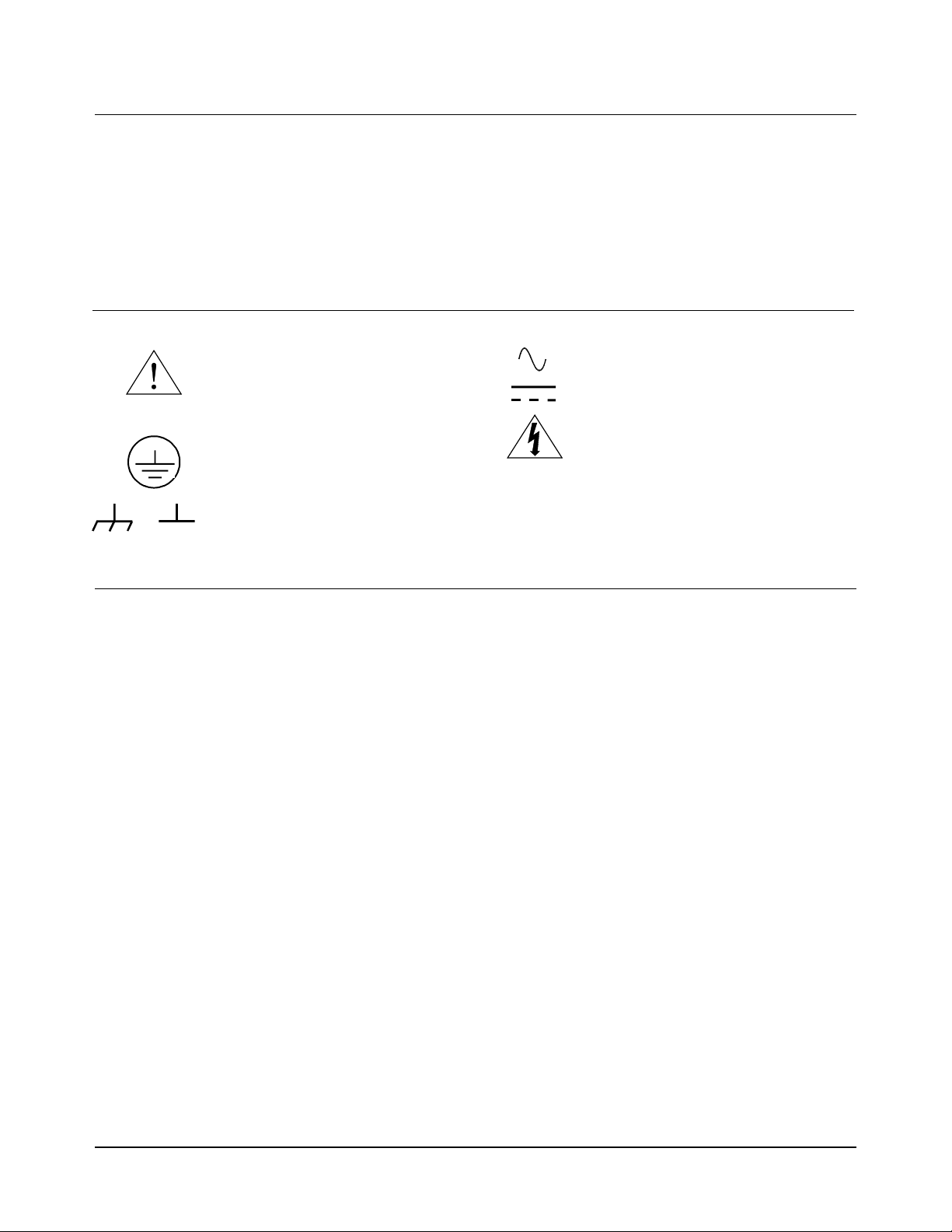
Safety Symbols
Instruction manual symbol affixed to
product. Indicates that the user must refer to
the manual for specific WARNING or
CAUTION information to avoid personal
injury or damage to the product.
Indicates the field wiring terminal that must
be connected to earth ground before
operating the equipment — protects against
electrical shock in case of fault.
or
Frame or chassis ground terminal—typ ically
connects to the equipment's metal frame.
WARNING
CAUTION
Alternating current (AC)
Direct current (DC).
WARNING, RISK OF ELECTRIC SHOCK.
Calls attention to a procedure, practice, or
condition that could cause bodily injury or
death.
Calls attention to a procedure, practice, or
condition that could possibly cause damage to
equipment or permanent loss of data.
WARNINGS
The following general safety precautions must be observed during all phases of operation, service, and repair of this product. Failure to
comply with these precautions or with specific warnings elsewhere in this manual violates safety standards of design, manufacture, and
intended use of the product. Agilent Technologies assumes no liability for the customer's failure to comply with these requirements.
Ground the equipment: For Safety Class 1 equipment (equipment having a protective earth terminal), an uninterruptible safety earth
ground must be provided from the mains power source to the product input wiring terminals or supplied power cable.
DO NOT operate the product in an explosive atmosphere or in the presence of flammable gases or fumes.
For continued protection against fire, replace the line fuse(s) only with fuse(s) of the same voltage and current rating and type. DO NOT
use repaired fuses or short-circuited fuse holders.
Keep away from live circuits: Operating personnel must not remove equipment covers or shields. Procedures involving the removal of
covers or shields are for use by service-trained personnel only. Under certain conditions, dangerous voltages may exist even with the
equipment switched off. To avoid dangerous electrical shock, DO NOT perform procedures involving cover or shield removal unless you
are qualified to do so.
DO NOT operate damaged equipment: Whenever it is possible that the safety protection features built into this product have been
impaired, either through physical damage, excessive moisture, or any other reason, REMOVE POWER and do not use the product until
safe operation can be verified by service-trained personnel. If necessary, return the product to Agilent for service and repair to ensure that
safety features are maintained.
DO NOT service or adjust alone: Do not attempt internal service or adjustment unless another person, capable of rendering first aid and
resuscitation, is present.
DO NOT substitute parts or modify equipment: Because of the danger of introducing additional hazards, do not install substitute parts
or perform any unauthorized modification to the product. Return the product to Agilent for service and repair to ensure that safety features
are maintained.
Measuring high voltages is always hazardous: ALL multimeter input terminals (both front and rear) must be considered hazardous
whenever inputs greater than 42V (dc or peak) are connected to ANY input terminal.
Permanent wiring of hazardous voltage or sources capable of delivering grater than 150 VA should be labeled, fused, or in some other
way protected against accidental bridging or equipment failure.
DO NOT leave measurement terminals energized when not in use.
DO NOT use the front/rear switch to multiplex hazardous signals between the front and rear terminals of the multimeter.
3

DECLARATION OF CONFORMITY
According to ISO/IEC Guide 22 and CEN/CENELEC EN 45014
Manufacturer’s Name: Agilent Technologies, Incorporated
Manufacturer’s Address:
815 14
Loveland, CO 80537
USA
Declares, that the product
Product Name: Multimeter
Model Number: 3458A
Product Options: This declaration covers all options of the above product(s).
Conforms with the following European Directives:
The product herewith complies with the requirements of the Low Voltage Directive 73/23/EEC and the EMC Directive 89/336/EEC
(including 93/68/EEC) and carries the CE Marking accordingly
Conforms with the following product standards:
th
ST. S.W.
EMC Standard
IEC 61326-1:1997+A1:1998 / EN 61326-1:1997+A1:1998
CISPR 11:1990 / EN 55011:1991
IEC 61000-4-2:1995+A1:1998 / EN 61000-4-2:1995
IEC 61000-4-3:1995 / EN 61000-4-3:1995
IEC 61000-4-4:1995 / EN 61000-4-4:1995
IEC 61000-4-5:1995 / EN 61000-4-5:1995
IEC 61000-4-6:1996 / EN 61000-4-6:1996
IEC 61000-4-11:1994 / EN 61000-4-11:1994
Canada: ICES-001:1998
Australia/New Zealand: AS/NZS 2064.1
The product was tested in a typical configuration with Agilent Technologies test systems.
Safety
IEC 61010-1:1990+A1:1992+A2:1995 / EN 61010-1:1993+A2:1995
Canada: CSA C22.2 No. 1010.1:1992
UL 3111-1: 1994
8 March 2001
Date
Limit
Group 1 Class A
4kV CD, 8kV AD
3 V/m, 80-1000 MHz
0.5kV signal lines, 1kV power lines
0.5 kV line-line, 1 kV line-ground
3V, 0.15-80 MHz I cycle, 100%
Dips: 30% 10ms; 60% 100ms
Interrupt > 95%@5000ms
Ray Corson
Product Regulation Program Manager
Authorized EU-representative: Agilent Technologies Deutschland GmbH, Herrenberger Strabe 130, D 71034 Böblingen, Germany
For further information, please contact your local Agilent Technologies sales office, agent or distributor.
Revision: B.01 Issue Date: March 2001
4

Preface
This manual contains installation information, operating and programming information, and configuration information for
the 3458A Multimeter. The manual consists of the following chapters:
Chapter 1 Installation and Maintenance
This chapter contains information on initial inspection, installation, and maintenance. It also contains lists of the
multimeter' s available options and accessories.
Chapter 2 Getting Started
This chapter covers the fundamentals of multimeter operation. It shows you how to use the multimeter's front panel, how to
send commands to the multimeter from remote, and how to retrieve data from remote.
Chapter 3 Configuring for Measurements
This chapter shows how to configure the multimeter for all types of measurements except digitizing (digitizing is covered
in Chapter 5). This chapter also shows you how to use subprogram and state memory, the input buffer, and the status
register.
Chapter 4 Making Measurements
This chapter discusses the methods for triggering measurements, discusses the reading formats, shows how to use reading
memory, and how to transfer readings across the GPIB bus. This chapter also discusses how to increase the reading rate,
how to use the multimeter's EXTOUT signal, and how to use the math operations.
Chapter 5 Digitizing
Digitizing is the process of converting a continuous analog signal into a series of discrete samples (readings). This chapter
discusses the various ways to digitize signals, the importance of the sampling rate, and how to use level triggering.
Chapter 6 Command Reference
This chapter discusses the multimeter's language (HPML) and contains detailed descriptions of each command in the
language. Commands are listed in alphabetical order.
Chapter 7 BASIC Programming Language
This chapter describes the BASIC commands supported by the 3458A's internal BASIC language operating system. With
this feature, many of your special requirements can be easily satisfied by writing and downloading a simple BASIC
subprogram to customize the multimeter's behavior.
Appendices
The appendices contain the multimeter's specifications, information on the GPIB commands recognized by the multimeter,
information on locking-out the front/rear terminals switch, and contains product notes concerning digitizing and
maximizing the multimeter's reading rate and throughput.
5

6

Contents
Chapter 1 Installation and Maintenance
Introduction ...........................................................15
Initial Inspection ....................................................15
Options and Accessories ........................................16
Installing the Multimeter .......................................17
Grounding Requirements .................................17
Line Power Requirements ................................17
Setting the Line Voltage Switches ...................18
Installing the Line Power Fuse ......................... 18
Power Cords ..................................................... 18
Connecting the GPIB Cable .............................19
The GPIB Address ............................................20
Mounting the Multimeter .................................20
Installation Verification ....................................21
Maintenance ...........................................................21
Replacing the Line Power Fuse ........................21
Replacing a Current Fuse ................................. 21
Repair Service ..................................................22
Chapter 2 Getting Started
Introduction ...........................................................25
Before Applying Power .........................................25
Applying Power .....................................................25
Power-On Self-Test .......................................... 25
Power-On State .................................................25
The Display ......................................................26
Operating from the Front Panel .............................27
Making a Measurement .................................... 28
Changing the Measurement Function ...............28
Autorange and Manual Ranging ....................... 29
Self-Test ...........................................................30
Reading the Error Register ...............................31
Resetting the Multimeter ..................................32
Using the Configuration Keys .......................... 32
Using the MENU Keys .....................................36
Query Commands .............................................37
Display Control ................................................37
Digits Displayed ...............................................39
Recall ................................................................39
User-Defined Keys ...........................................40
Installing the Keyboard Overlay ......................41
Operating from Remote .........................................42
Input/Output Statements ...................................42
Reading the GPIB Address ...............................42
Changing the GPIB Address ............................43
Sending a Remote Command ........................... 43
Getting Data from the Multimeter ................... 43
The Local Key .................................................. 44
Chapter 3 Configuring for Measurements
Introduction ........................................................... 47
General Configuration ........................................... 47
Self-Test ........................................................... 47
Reading the Error Registers ............................. 48
Calibration ........................................................ 48
Selecting the Input Terminals .......................... 50
Guarding .......................................................... 51
Suspending Readings ....................................... 51
Presetting the Multimeter ................................. 52
Specifying a Measurement Function ............... 53
Autorange ......................................................... 53
Specifying the Range ....................................... 54
Configuring for DC or Resistance Measurements 54
DC Voltage ...................................................... 54
DC Current ....................................................... 55
Resistance ........................................................ 56
Configuring the A/D Converter ....................... 58
Autozero ........................................................... 61
Offset Compensation ....................................... 62
Fixed Input Resistance ..................................... 62
Configuring for AC Measurements ....................... 62
AC or AC+DC Voltage .................................... 62
AC or AC+DC Current .................................... 64
Frequency or Period ......................................... 65
Specifying Bandwidth ...................................... 66
Setting the Integration Time ............................ 67
Specifying Resolution ...................................... 68
Configuring for Ratio Measurements .................... 70
Specifying Ratio Measurements ...................... 71
Using Subprogram Memory .................................. 71
Storing a Subprogram ...................................... 71
Executing a Subprogram .................................. 72
Suspending Subprogram Execution ................. 72
Nested Subprograms ........................................ 73
Autostart Subprogram ...................................... 73
Compressing Subprograms .............................. 73
Deleting Subprograms ..................................... 74
Using State Memory ............................................. 74
Storing States ................................................... 74
Recalling States ................................................ 74
Contents 7

Deleting States ..................................................75
Using the Input Buffer ........................................... 75
Using the Status Register .......................................75
Reading the Status Register .............................. 77
Interrupts ..........................................................77
Chapter 4 Making Measurements
Introduction ...........................................................81
Triggering Measurements ......................................81
The Trigger Arm Event .................................... 82
The Trigger Event ............................................82
The Sample Event ............................................82
Event Choices ...................................................82
Making Continuous Readings ..........................82
Making Single Readings .................................. 83
Making Multiple Readings ...............................83
Multiple Trigger Arming ..................................84
Making Synchronous Readings ........................ 84
Making Timed Readings ..................................85
Making Delayed Readings ...............................86
External Triggering ..........................................87
Event Combinations .........................................88
Reading Formats ....................................................92
ASCII ................................................................92
Single and Double Integer ................................ 92
Single Real .......................................................93
Using Reading Memory .........................................94
Memory Formats ..............................................95
Recalling Readings ...........................................96
Sending Readings Across the Bus ......................... 98
Output Formats .................................................98
Output Termination .......................................... 99
Using the SINT or DINT Output Format ......... 99
Using the SREAL Output Format ..................101
Using the DREAL Output Format ..................101
Increasing the Reading Rate ................................102
High-Speed Mode ........................................... 102
Configuring for Fast Readings ....................... 103
High-Speed Transfer across GPIB ................. 107
High-Speed Transfer from Memory ...............108
Determining the Reading Rate .......................109
The EXTOUT Signal ........................................... 110
Reading Complete .......................................... 112
Burst Complete ............................................... 113
Input Complete ...............................................114
Aperture Waveform ........................................114
Service Request .............................................. 114
EXTOUT ONCE ............................................115
Math Operations .................................................. 116
Real-Time vs. Post-Process ........................... 116
Enabling Math Operations ............................. 116
Math Registers ............................................... 117
NULL ............................................................. 117
SCALE ........................................................... 119
Percent ............................................................ 120
DB .................................................................. 120
DBM .............................................................. 121
Statistics ......................................................... 122
Pass/Fail ......................................................... 123
FILTER .......................................................... 124
RMS ............................................................... 125
Measuring Temperature ................................. 125
Chapter 5 Digitizing
Introduction ......................................................... 129
Digitizing Methods .............................................. 129
The Sampling Rate .............................................. 131
Level Triggering .................................................. 132
Level Triggering Examples ............................ 132
Level Filtering ................................................ 134
DCV Digitizing ................................................... 134
DCV Remarks ................................................ 135
DCV Example ................................................ 136
Direct-Sampling .................................................. 137
Direct Sampling Remarks .............................. 138
Direct Sampling Example .............................. 139
Sub-Sampling ...................................................... 139
Sub-Sampling Fundamentals ......................... 140
The Sync Source Event .................................. 141
Sub-Sampling Remarks ................................. 143
Sending Samples to Memory ......................... 144
Sending Samples to the Controller ................ 144
Viewing Sampled Data ....................................... 146
Chapter 6 Command Reference
Introduction ......................................................... 151
Language Conventions ................................... 152
Command Termination .................................. 152
Multiple Commands ....................................... 152
Parameters ...................................................... 152
Query Commands .......................................... 153
Commands by Functional Group ........................ 155
Commands vs. Measurement Functions ............. 156
ACAL ............................................................. 157
ACBAND ....................................................... 158
ACDCI, ACDCV, ACI, ACV ........................ 159
ADDRESS ..................................................... 159
8 Contents

APER ..............................................................160
ARANGE ....................................................... 160
AUXERR? ...................................................... 161
AZERO ........................................................... 162
BEEP ..............................................................164
CAL ................................................................164
CALL ..............................................................164
CALNUM? .....................................................165
CALSTR ......................................................... 165
COMPRESS ...................................................166
CONT ............................................................. 167
CSB ................................................................167
DCI, DCV .......................................................168
DEFEAT ......................................................... 168
DEFKEY ........................................................ 169
DELAY .......................................................... 170
DELSUB ........................................................ 171
DIAGNOST ....................................................171
DISP ...............................................................171
DSAC, DSDC .................................................172
EMASK .......................................................... 174
END ................................................................176
ERR? ..............................................................177
ERRSTR? .......................................................178
EXTOUT ........................................................ 178
FIXEDZ ..........................................................180
FREQ ..............................................................181
FSOURCE ...................................................... 182
FUNC ............................................................. 183
ID? ..................................................................185
INBUF ............................................................ 185
ISCALE? ........................................................ 187
LEVEL ........................................................... 188
LFILTER ........................................................190
LFREQ ........................................................... 190
LINE? .............................................................192
LOCK ............................................................. 192
MATH ............................................................ 193
MCOUNT? .....................................................195
MEM ..............................................................196
MENU ............................................................ 197
MFORMAT ....................................................198
MMATH .........................................................199
MSIZE ............................................................202
NDIG ..............................................................203
NPLC ..............................................................204
NRDGS .......................................................... 206
OCOMP .......................................................... 208
OFORMAT .................................................... 209
OHM, OHMF ................................................. 213
OPT? .............................................................. 213
PAUSE ........................................................... 214
PER ................................................................ 215
PRESET ......................................................... 216
PURGE .......................................................... 218
QFORMAT .................................................... 218
R ..................................................................... 220
RANGE .......................................................... 220
RATIO ........................................................... 223
RES ................................................................ 224
RESET ........................................................... 225
REV? .............................................................. 227
RMATH ......................................................... 227
RMEM ........................................................... 228
RQS ................................................................ 229
RSTATE ........................................................ 230
SCAL ............................................................. 231
SCRATCH ..................................................... 231
SECURE ........................................................ 231
SETACV ........................................................ 232
SLOPE ........................................................... 233
SMATH .......................................................... 234
SRQ ................................................................ 235
SSAC, SSDC .................................................. 236
SSPARM? ...................................................... 239
SSRC .............................................................. 239
SSTATE ......................................................... 243
STB? .............................................................. 244
SUB ................................................................ 245
SUBEND ........................................................ 247
SWEEP .......................................................... 247
T ..................................................................... 250
TARM ............................................................ 250
TBUFF ........................................................... 252
TEMP? ........................................................... 253
TERM ............................................................ 253
TEST .............................................................. 254
TIMER ........................................................... 254
TONE ............................................................. 255
TRIG .............................................................. 255
Chapter 7 BASIC Language for the 3458A
Introduction ......................................................... 261
How It Works ...................................................... 261
BASIC Language Commands ............................. 262
Variables and Arrays ...................................... 262
Contents 9

Math Operations .............................................262
Subprogram Definition/Deletion .................... 263
Subprogram Execution Commands ................263
Looping and Branching ..................................263
Binary Programs .............................................263
New Multimeter Commands ...............................264
3458A BASIC Language Example Program ....... 265
Variables and Arrays ...........................................266
Type Declarations ........................................... 266
Type Conversions ...........................................267
Using Variables .............................................. 267
Arrays .............................................................268
General Purpose Math .........................................269
Math Operators ...............................................270
Math Hierarchy ............................................... 272
Math Errors .....................................................272
Making Comparisons Work ........................... 272
Subprograms ........................................................273
Writing and Loading Subprograms ..................... 274
Subprogram Command Types .............................275
Definition/Deletion Commands ..................... 275
Execution Commands ..................................... 277
Conditional Statements in Subprograms ............. 278
FOR...NEXT Loops ........................................278
WHILE Loops ................................................ 279
IF...THEN Branching .....................................280
Appendix A Specifications
Appendix B GPIB Commands
Introduction .........................................................303
ABORT 7 (IFC) ..............................................304
CLEAR (DCL or SDC) ..................................304
LOCAL (GTL) ...............................................304
LOCAL LOCKOUT (LLO) ...........................305
REMOTE ........................................................ 305
SPOLL (Serial Poll) .......................................306
TRIGGER (GET) ...........................................307
Appendix C Procedure to Lock Out Front/Rear
Terminals and Guard Terminal
Switches
Introduction .........................................................311
Tools Required ....................................................311
Procedure .............................................................311
Covers Removal Procedure ............................312
Guard Pushrod Removal Procedure ...............314
Front/Rear Pushrod Removal Procedure ........ 314
Switch Cap Installation Procedure ................. 316
Covers Installation Procedure ........................ 318
Appendix D Optimizing Throughout and
Reading Rate
Introducing the 3458A ........................................ 321
Application Oriented Command Language ... 321
Intrinsically Slow Measurements ................... 321
Maximizing the Testing Speed ............................ 322
Program Memory ........................................... 322
State Storage .................................................. 322
Reading Analysis ........................................... 322
Task Grouping and Sequence ........................ 322
System Uptime ............................................... 323
Purpose ................................................................ 323
Topics Covered in the Product Note include: 323
DC Volts, DC Current and Resistance ................ 323
Optimizing Through the DCV Path ............... 324
DC Current ..................................................... 326
Resistance ...................................................... 326
Optimizing Through the Track-and-Hold Path
(Direct Sampling and Subsampling) .............. 328
AC Volts and AC Current ................................... 328
Analog ACV .................................................. 328
Synchronous ACV ........................................ 328
Random ACV ................................................. 328
Comparison of ACV Modes .......................... 329
AC Current ..................................................... 329
Frequency and Period .................................... 330
Optimizing the Testing Process Through Task
Allocation ............................................................ 330
Math Operations ............................................. 330
Data Storage ................................................... 330
Output Formats .............................................. 331
State Storage and Program Memory .............. 331
Measurement List ........................................... 332
A Benchmark ...................................................... 333
Benchmark Results ........................................ 334
Still Faster ...................................................... 338
Appendix E High Resolution Digitizing With the
3458A
Introduction ......................................................... 349
Speed with Resolution ......................................... 349
Digitizing Analog Signals .............................. 350
Avoiding Aliasing .......................................... 350
Choice of Two Measurement Paths .................... 351
Using the DCV Path for Direct Sampling ...... 351
Using the Track-and-Hold Path for Direct or
Sequential Sampling ...................................... 352
10 Contents

Capturing the Data ...............................................352
High Speed Data Transfers ..................................355
Software Help The Wave Form Analysis Library 355
Starter Main Program ..................................... 357
Errors in Measurements ...................................... 358
Amplitude Errors ........................................... 359
Trigger and Timebase Errors ......................... 361
Contents 11

12 Contents

Chapter 1 Installation and Maintenance
Introduction ...........................................................15
Initial Inspection ....................................................15
Options and Accessories ........................................16
Installing the Multimeter .......................................17
Grounding Requirements .................................17
Line Power Requirements ................................17
Setting the Line Voltage Switches ...................18
Installing the Line Power Fuse ......................... 18
Power Cords ..................................................... 18
Connecting the GPIB Cable .............................19
The GPIB Address ............................................20
Mounting the Multimeter .................................20
Installation Verification ....................................21
Maintenance ...........................................................21
Replacing the Line Power Fuse ........................21
Replacing a Current Fuse ................................. 21
Repair Service ..................................................22
Serial Number .............................................22
Shipping Instructions ..................................22
Chapter 1 Installation and Maintenance 13

14 Chapter 1 Installation and Maintenance

Chapter 1 Installation and Maintenance
Introduction
This chapter contains information on initial inspection, installation, and
maintenance. It also contains lists of the multimeter's available options and
accessories. It's a good idea to read this chapter before making any electrical
connections to the multimeter.
Initial Inspection
WARNING If any of the following symptoms exist, or are expected, remove
the multimeter from service:
1. Visible damage.
2. Severe transport stress.
3. Prolonged storage under adverse conditions.
4. Failure to perform intended measurements or functions.
Do not use multimeter until safe operation can be verified by
service trained personnel.
The multimeter was carefully inspected before it left the factory. It should
be undamaged and in proper working order upon receipt. If the shipping
container or cushioning material is damaged, keep it, until the contents of
the shipment have been checked and the multimeter has been inspected.
When you unpack the multimeter, verify that the following items, in addition
to this user’s guide, are included:
• Quick Reference Guide (Qty. 1)
• Calibration Manual (Qty. 1)
• Line Power Cord (Qty. 1)
• Replacement line power fuses: 500mA T (Qty 1 for 220/240 operation),
1.5A NTD (Qty 1 for 100/120 operation)
• Keyboard Overlay (Qty. 2)
• Switch Lockout Caps (Qty. 2)
If the multimeter is damaged or the contents are incomplete, promptly notify
the nearest Agilent Technologies office.
Chapter 1 Installation and Maintenance 15

Options and Accessories
Table 1 lists the available options, and Table 2 lists the available accessories
for the multimeter.
Table 1. Available Options
Description Option
Number
Extended Reading Memory (expands to a total
of 148k-bytes)
High Stability Reference (4ppm/year) 002 03458-80002
Waveform Analysis Library 005 03458-80005
Front Handle Kit 907 5061-9688
Rack Flange Kit 908 5061-9674
Rack Flange Kit (with handles) 909 5061-9675
2 Additional Years of Return to Agilent
Hardware support W30
001 03458-87901
Part Number for
Field Retrofit
Table 2. Available Accessories
Description Model or Part Number
Extra User’s Guide, Quick Reference Guide, and Calibration Manual 03458-90000
Extra Quick Reference Guide 03458-90005
Extra Calibration Manual 03458-90015
User-Defined Key Overlay 03458-84303
Switch Lockout Cap (Qty 1) 03458-44103
1 Meter GPIB Cable 10833A
2 Meter GPIB Cable 10833B
4 Meter GPIB Cable 10833C
0.5 Meter GPIB Cable 10833D
Test Lead Set 34118A
Low thermal test lead pair, spade lug to spade lug, 0.9m 11053A
Low thermal test lead pair, spade lug to banana, 0.9m 11174A
Low thermal test lead pair, banana to banana, 0.9m 11058A
RF Detector Probe 34301A
40kV AC/DC High Voltage Probe 34300A
5kV AC/DC 1MHz High Voltage Probe 34119A
Clamp-On AC/DC Current Probe 34302A
Kelvin Probe Set (4-wires, 1m each) 11059A
Kelvin Clip Set (2 each) 11062A
Temperature Probe 34303A
2252
W Thermistor
5k
W Thermistor
1Ok
W Thermistor
W RTD stainless steel probe, alpha = 0.00385
100
100
W RTD for surface mount, alpha = 0.00385
40653A
40653B
40653C
40654A
40654B
16 Chapter 1 Installation and Maintenance

Installing the Multimeter
This section discusses the multimeter's grounding and power requirements
and contains instructions for installing the multimeter. (Refer to Appendix
C for instructions on how to install the switch lockout caps.) Figure 1 shows
the multimeter's rear panel. Many of the rear panel connectors and switches
are referenced in this section.
Grounding
Requirements
WARNING For protection from electrical shock, the power cord ground
Line Power
Requirements
Caution Possible multimeter damage. Before connecting the multimeter
Figure 1. Rear panel
The multimeter comes with a three-conductor AC power cable (see Figure 3).
The power cable must be connected to an approved three-contact electrical
outlet that has its ground conductor connected to an electrical ground (safety
ground). The multimeter's power jack and the supplied power cable meet
International Electrotechnical Commission (IEC) safety standards.
must not be defeated.
You can operate the multimeter from a single phase power source delivering
100 VAC, 120 VAC, 220 VAC, or 240 VAC (all values RMS), at 48 to 440
Hz. The power line voltage can vary by +/- 10% but cannot exceed 250 VAC
RMS. Maximum power consumption is 80 VA (Volt-Amps). The nominal
line voltage values and their corresponding limits are shown in Table 3.
to an AC power source, verify that the multimeter’s line voltage
selection switches are set to match the AC line voltage and that
the proper line fuse is installed. These topics are discussed in
the following sections.
Chapter 1 Installation and Maintenance 17

Table 3. Line Voltage Limits
Nominal Value (RMS) Allowable Limits (RMS)
100 VAC 90 VAC to 110 VAC
120 VAC 108 VAC to 132 VAC
220 VAC 198 VAC to 242 VAC
240 VAC 216 VAC to 250 VAC
Setting the Line
Voltage Switches
The line voltage selection is pre configured according to the country to which
it is shipped. Use the following procedure if you need to change this setting:
1. Remove the multimeter's line power cord before changing the
positions of the AC line voltage selection switches
2. With a small flat blade screwdriver, move the switches to the
appropriate positions as shown in Figure 2
3. Install the correct line power fuse as described in the next section.
Installing the Line
Power Fuse
The line power fuse must match the line voltage selection. For 100 VAC or
120 VAC operation install a 1.5A fuse. For 220 VAC or 240 VAC operation
install a 500 mAT fuse.
The line power fuse holder is located on the right side of the multimeter's
rear panel (see Figure 1). To install a fuse, make sure the multimeter's power
cord is removed. Insert one end of the fuse into the fuse cap. Insert the
fuse/cap assembly into the fuse holder. With a small flatblade screwdriver,
push in on the fuse cap and rotate it clockwise.
Power Cords Figure 3 shows the various multimeter power cords and their Agilent part
numbers. If you received the wrong power cord, notify your Agilent sales
office for replacement.
18 Chapter 1 Installation and Maintenance
Figure 2. AC line voltage switch positions

Power Cords
Australia Denmark Europe Great Brittain Switzerland U.S.A U.S.A.
Country Part Number Option Voltage
Australia 8120-1369 901 250V 6A
Denmark 1820-2956 912 259V 6A
Europe 1820-1689 902 250V 6A
Great Brittain 1820-1351 900 250V 6A
Switzerland 1820-2104 906 250V 6A
United States 1820-1378 903 120 10A
United States 1820-0698 904 240V 10A
Power cords supplied by Agilent have polarities matched to the power input socket
on the instrument.
NOTE:
*CSA certification includes only these power cords
Plugs are viewed from connector and. Shape of molded plug may vary
within country
Figure 3. Power Cords
Connecting the GPIB
Cable
Attach the GPIB1 cable to the 24-pin GPIB connector on the rear panel of
the multimeter. Finger tighten the two screws on the cable connector.
Figure 4 shows a typical GPIB connection between the multimeter and a
controller.
1. GPIB (General Purpose Interface Bus) is an implementation of IEEE Standard 488-1978 and ANSI MC 1.1.
Chapter 1 Installation and Maintenance 19

Figure 4. Typical GPIB Connections
A total of 15 devices can be connected together on the same GPIB bus. The
cables have single male/female connectors on each end so that several cables
can be stacked. The length of the GPIB cables must not exceed 20 meters (65
feet) total, or 2 meters (6.5 feet) per device, whichever is less.
The GPIB Address You can change the multimeter's GPIB address using the ADDRESS
command. Refer to "Changing the GPIB Address", in Chapter 2, for a
procedure on how to change the GPIB address. The multimeter leaves the
factory with the address set to decimal 22. The corresponding ASCII code is
a listen address of 6 and a talk address of V.
Note The examples in this manual are intended for Hewlett-Packard Series
200\300 computers using the BASIC language. They assume a GPIB
interface select code of 7 and a device address of 22 resulting in a combined
GPIB address of 722.
Mounting the
Multimeter
20 Chapter 1 Installation and Maintenance
The multimeter comes equipped with four feet, which allow it to be used as
a bench instrument. It also has two tilt stands that allow you to elevate the
front of the multimeter. The multimeter can be mounted in a standard 19-inch
rack using the optional rack mount kits listed in Table 1.

Installation
Verification
Maintenance
The following program verifies that the multimeter is operating and can
communicate with the controller over the GPIB bus.
10 PRINTER IS 1
20 OUTPUT 722;"ID?"
30 ENTER 722; IDENT$
40 PRINT IDENT$
50 END
If the multimeter has been correctly installed, the message HP 3458A will
be printed on the designated system printer. If no message is printed, make
sure power is applied to the multimeter. Also check the GPIB connections,
the interface address setting, and the multimeter's address.
This section describes how to replace the multimeter's fuses and how to
obtain repair service.
Replacing the Line
Power Fuse
Replacing a Current
Fuse
The line power fuse holder is located on the right side of the multimeter's
rear panel. Before replacing the fuse, disconnect the multimeter's line power.
To replace the fuse, use a small flatblade screwdriver to push in on the fuse
cap and rotate it counterclockwise. Remove the fuse cap and replace the fuse
with the appropriate type (see Table 4). (The Agilent part number for the gray
line power fuse cap is 2110-0565.) Re-install the fuse cap and apply power.
Table 4. Replacement Power Line Fuses and Caps
Line Voltage Power Line Fuse
100 or 120 VAC (Nominal) 1.5A NTD, Agilent Part Number 2110-0043
220 or 240 VAC (Nominal) 500mAT SB, Agilent Part Number
2110-0202
Each of the front and rear current terminals (labeled I) contains a current fuse.
To access the fuse, unscrew (rotate counterclockwise) the current terminal
binding post knob until it stops. Push in on the terminal and rotate it
clockwise. The entire terminal/fuse assembly can now be removed as shown
in Figure 5. If necessary, replace the fuse with a 1A 250V NTD fuse (Agilent
part number 2110-0001). (CAUTION: never use a slow-blow fuse as a
current fuse; multimeter damage will result.) Replace the terminal/fuse
assembly by pushing it in and turning counterclockwise until the assembly
locks in place.
Chapter 1 Installation and Maintenance 21
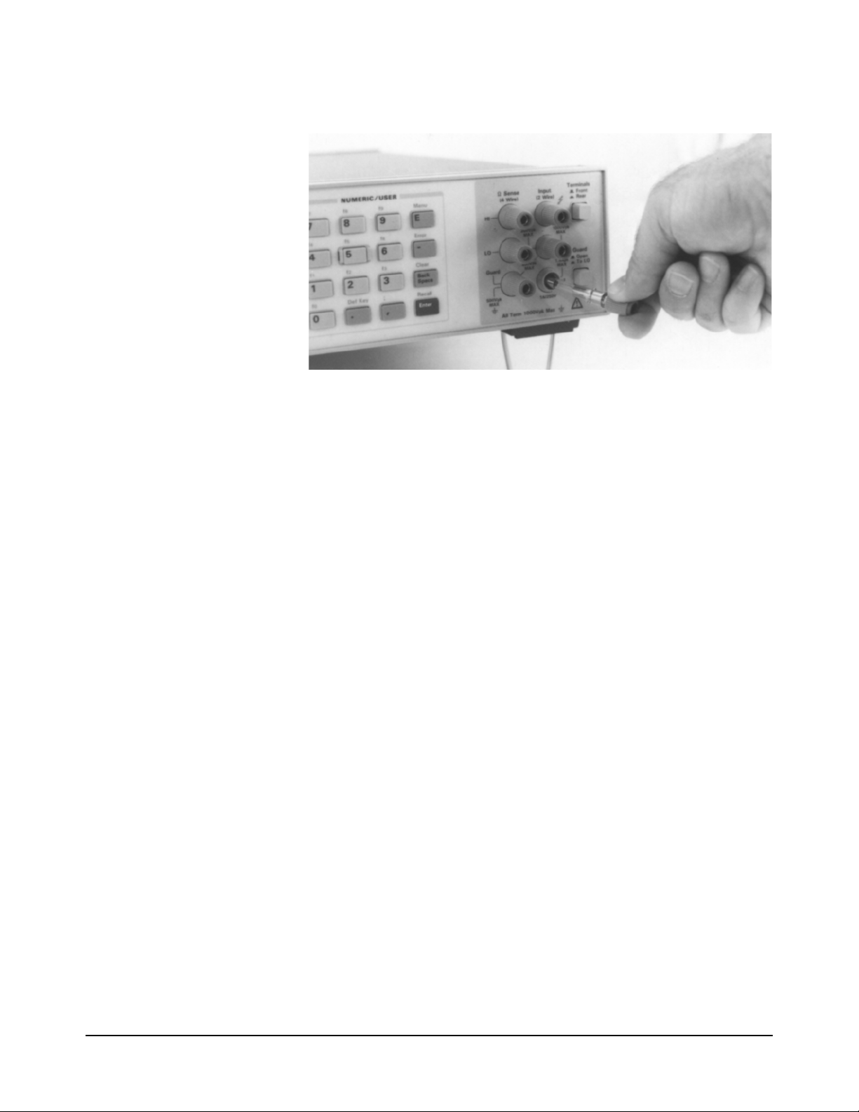
Figure 5. Current Terminal/Fuse Assembly
Repair Service You may have the multimeter repaired at an Agilent Technologies service
center whether it is under warranty or not. Contact the nearest Agilent Sales
Office for shipping instructions prior to returning the instrument.
Serial Number Agilent instruments are identified by a two part, ten-character serial number
of the form 0000A00000. The first four digits are the same for all identical
products. They change only when a change is made to the product. The letter
indicates the country of origin. An A indicates the product was made in the
United States of America. The last five digits are unique to each instrument.
The multimeter's serial number is located to the right of the multimeter's rear
terminals.
Shipping Instructions If you need to ship the multimeter, be certain that the multimeter is in a
protective package (use the original shipping containers and cushioning
materials) to prevent transit damage. Such damage is not covered by
warranty. Attach a tag to the shipment identifying the owner and indicating
the service or repair needed. Include the model number and serial number of
the multimeter. We suggest that you insure the shipment.
22 Chapter 1 Installation and Maintenance

Chapter 2 Getting Started
Introduction ...........................................................25
Before Applying Power .........................................25
Applying Power .....................................................25
Power-On Self-Test .......................................... 25
Power-On State .................................................25
The Display ......................................................26
Operating from the Front Panel .............................27
Making a Measurement .................................... 28
Changing the Measurement Function ...............28
Autorange and Manual Ranging ....................... 29
Hold .............................................................29
Manual Ranging ..........................................30
Self-Test ...........................................................30
Reading the Error Register ...............................31
Resetting the Multimeter ..................................32
Using the Configuration Keys .......................... 32
Selecting a Parameter ..................................33
Default Values .............................................34
Numeric Parameters ....................................34
Exponential Parameters ...............................35
Multiple Parameters ....................................35
Using the MENU Keys .....................................36
Query Commands .............................................37
Standard Queries .........................................37
Additional Queries ...................................... 37
Display Control ................................................37
Clearing the Display ....................................37
Display Editing ............................................38
Viewing Long Displays ............................... 38
MORE INFO Display .................................39
Digits Displayed ...............................................39
Recall ................................................................39
User-Defined Keys ...........................................40
Installing the Keyboard Overlay ......................41
Operating from Remote .........................................42
Input/Output Statements ...................................42
Reading the GPIB Address ...............................42
Changing the GPIB Address ............................43
Sending a Remote Command ...........................43
Getting Data from the Multimeter ....................43
The Local Key ..................................................44
Chapter 2 Getting Started 23

24 Chapter 2 Getting Started

Chapter 2 Getting Started
Introduction
This chapter is intended for the novice multimeter user. It shows you how to
use the multimeter's front panel, how to send commands to the multimeter
from remote, and how to retrieve data from remote. Since front panel
operation is discussed first, it covers important topics such as the power-on
state, display annunciators, the various ways to select or enter parameters,
and how to make a simple DC voltage measurement. For this reason, you
should read the entire chapter even if you intend to use the multimeter
primarily from remote.
Before Applying Power
• Make sure the line voltage selection switches on the multimeter's rear
panel are set to match the local line voltage.
• Make sure the proper line fuse is installed.
If you have any questions concerning installation or power requirements,
refer to Chapter 1.
Applying Power
To turn on the multimeter, depress the front panel Power switch. If the
multimeter does not appear to turn on, verify that the multimeter is connected
to line power. If line power is not the problem, remove the power cord and
check the line power fuse and the line voltage selection switch settings.
Power-On Self-Test When power is applied, the multimeter performs a limited power-on self-test.
This test verifies that the multimeter is operating but does not necessarily
verify that measurements will be accurate.
Power-On State When the power-on self-test is finished, the multimeter beeps once,
automatically triggers, automatically selects the range, and performs DC
voltage measurements. Also, the multimeter has set many of its commands
to predefined power-on values as shown in Table 5, This is called the
power-on state.
Chapter 2 Getting Started 25

Table 5. Power-On State
Command Description
ACBAND 20, 2E6 AC bandwidth 20Hz - 2MHz
AZERO ON Autozero enabled
DCV AUTO DC voltage, autorange
DEFEAT OFF Defeat disabled
DELAY -1 Default delay
DISP ON Display Enabled
EMASK 32767 Enable all error conditions
END OFF Disable GPIB EOI function
EXTOUT ICOMP, NEG Input complete EXTOUT signal, negative pulse
FIXEDZ OFF Disable fixed input resistance
FSOURCE ACV Frequency and period source is AC voltage
INBUF OFF Disable input buffer
LEVEL 0, AC Level trigger at 0%, AC-coupled
LFILTER OFF Level filter disabled
LFREQ 50 or 60 Measured line frequency rounded to 50 or 60Hz
LOCK OFF Keyboard enabled
MATH OFF Disable real-time math
MEM OFF Disable reading memory (last memory operation = FIFO)
MFORMAT SREAL Single real reading memory format
MMATH OFF Disable post-process math
NDIG 7 Display 7.5 digits
NPLC 10 10 power line cycles of integration time
NRDGS 1, AUTO 1 reading per trigger, auto sample event
OCOMP OFF Disable offset compensated resistance
OFORMAT ASCII ASCII output format
QFORMAT NORM Normal query format
RATIO OFF Disable ratio measurements
RQS 0 (or 8) 0 disables status register conditions (if power-on
SETACV ANA Analog AC voltage mode
SLOPE POS Positive slope for level triggering
SSRC LEVEL, AUTO Level sync source event, auto synchronous AC voltage
SWEEP lOOE-9,1024 Sample interval 100 nanoseconds, 1024 samples
TARM AUTO Auto trigger arm event
TBUFF OFF Disable external trigger buffering
TIMER 1 1 second timer interval
TRIG AUTO Auto trigger event
DEGREE = 20 REF=l SCALE = 1 RES=50 PERC = 1
SRQ was on when power was removed, value = 8).
All math registers set to 0 except:
The Display In the power-on state, the display is continuously updated with each new DC
26 Chapter 2 Getting Started
voltage reading. Along the bottom of the display are a series of annunciators.
These annunciators alert you to a variety of conditions. For example, the
SMPL annunciator flashes whenever the multimeter has completed a
reading. Table 6 describes the meaning of each display annunciator.

Table 6. Display Annunciators
Display Annunciator Description
SMPL Flashes whenever a reading is completed
REM The multimeter is in the GPIB remote mode
SRQ The multimeter has generated a GPIB service request
TALK The multimeter is addressed to talk on GPIB
LSTN The multimeter is addressed to listen on GPIB
AZERO OFF Autozero is disabled
MRNG Autorange is disabled (the multimeter is using a fixed range)
MATH One or two real-time or post-process math operations enabled
ERR An error has been detected
SHIFT The shift key has been pressed
MORE INFO More information concerning the present configuration is available
(use the right arrow key to view the information)
Note If the ERR annunciator is illuminated at this point, an error was detected
during or after the power-on self-test. You will learn how to determine the
error later in this chapter in “Reading the Error Register”.
Operating from the Front Panel
This section shows you how to make a simple DC voltage measurement, how
to use the various front panel keys, and describes the multimeter functions
important to front panel operation. Figure 6 shows the multimeter's front
panel features.
Figure 6. Front Panel
Chapter 2 Getting Started 27

Making a
Measurement
In the power-on state, DC voltage measurements are selected and the
multimeter automatically triggers and selects the range. In the power-on
state, you can make DC voltage measurements simply by connecting a DC
voltage to the input terminals as shown in Figure 7. The connections shown
in Figure 7 also apply for AC voltage, 2-wire resistance, AC+DC voltage,
digitizing, and frequency or period measurements from a voltage input
source. Refer to Chapter 3 for a CAUTlON concerning the multimeter's
maximum input voltage and current.
Figure 7. Standard 2-wire (plus guard) measurements
Changing the
Measurement
Function
The row of keys located directly under the display (FUNCTION keys) select
the multimeter's standard measurement functions. Table 7 shows the
FUNCTION keys and the measurement function selected by each.
28 Chapter 2 Getting Started

Table 7. Function Keys
Autorange and
Manual Ranging
Hold This choice allows you to shut off autoranging. To do this, let autorange
Note When you press the blue shift key, the display’s SHIFT annunicator
In addition to the functions selected by the FUNCTION keys, the multimeter
can perform direct-sampled or sub-sampled digitizing, ratio measurements,
and AC or AC+DC voltage measurements using the synchronous or random
measurement methods. These functions can be selected from the front panel
by accessing the appropriate command(s) using the alphabetic menu keys
(these keys are discussed later in this section under "Using the MENU
Keys"). For more information on any measurement function or method, refer
to Chapter 1.
In the power-on state, the multimeter automatically selects the appropriate
measurement range. This is called autorange. In many cases, you will
probably want to continue using autorange. However, you have two other
ranging choices: hold and manual ranging.
choose a range and then press:
Hold
illuminates. The shifted keyboard functions are printed in blue above the
keys.
Chapter 2 Getting Started 29

Notice the display's MRNG (manual range) annunciator is on. This
annunciator is on whenever you are not using autorange.
Manual Ranging The second choice lets you manually select the range. When the multimeter
is in the measurement mode (that is, the multimeter is making and displaying
measurements or the display is showing OVLD) you can change the range
by pressing the up or down arrow keys. To go to a higher range, press:
By repeatedly pressing the up arrow key, you can increment up to the highest
range. When you reach the highest range, pressing the up arrow key no longer
changes the range. To go to a lower range, press:
By repeatedly pressing the down arrow key, you can decrement down to the
lowest range. When you reach the lowest range, pressing the down arrow key
no longer changes the range. To return to autoranging, press:
Auto
Self-Test When you applied power to the multimeter, it automatically performed a
limited power-on self-test. Before you start making measurements, however,
you may want to have more confidence that the multimeter is fully
operational. This is the job of the self-test. The self-test performs a series of
tests that check the multimeter's operability and accuracy.
Note Always disconnect any input signals before you run self-test. If you leave
an input signal connected to the multimeter, it cause a self-test failure.
The self-test takes over 50 seconds. To run self-test press:
Test
If the self-test passed, the display shows:
When self-test passes, you have a high confidence that the multimeter is
operational and, assuming proper calibration and autocalibration, that
measurements will be accurate.
30 Chapter 2 Getting Started
If any of the tests failed, the ERR annunciator illuminates and the display
shows:

If the self-test failed, one or more error conditions have been detected. Refer
to the next section "Reading the Error Register".
Reading the Error
Register
Note When you get a hardware error (200-series prefix), run the self-test again. If
Whenever the display's ERR annunciator is illuminated, one or more errors
have been detected. A record of hardware errors is stored in the auxiliary
error register. A record of programming and syntax errors is stored in the
error register. To read the error record(s), press:
Error
_
The lowest numbered error and a description of the error is displayed. For
example, a possible error message is:
Use the right arrow key to view the entire message. When the error message
has a 100-series numeric prefix (e.g., 105), it indicates a programming or
syntax error. A 200-series prefix (e.g., 209) indicates a hardware error.
you repeatedly get the error, the multimeter may need repair.
If the ERR annunciator is still illuminated, more errors have been recorded.
Repeat the above key sequence until all errors have been read and the ERR
annunciator is no longer illuminated. When you have read all the errors, the
error annunciator goes off. If you try to read another error, the display shows:
You do not have to run self-test to get an error. The multimeter detects errors
that occur while entering data, when changing functions or ranges, and so
on. The multimeter beeps whenever it detects an error.
Whenever you want to clear information (such as an error description) from
the display and return it to displaying measurements, press:
Clear
Back
Space
Note You can also clear the display by repeatedly pressing the Back Space key
Chapter 2 Getting Started 31

(unshifted).
Resetting the
Multimeter
Caution Pressing the shifted front panel Reset key performs the
Many times during operation, you may wish to return to the power-on state.
The front panel Reset key returns you to the power-on state without having
to cycle the multimeter's power. To reset the multimeter, press:
Reset
The multimeter begins the reset process with a display test which illuminates
all display elements including the annunciators as shown in Figure 8. (By
holding down the Reset key, the multimeter continuously performs its
display test).
Figure 8. Display Test
power-on sequence which has the same effect as cycling the
multimeter’s power. This destroys any stored reading and
compressed subprograms, sets the power-on SRQ bit in the
status register (these functions are discussed later in this
manual), resets the A/D converter reference frequency and
performs the power-on self test. Executing the RESET
command from the alphabetic command menu (MENU keys)
returns the mulitmeter to the power-on state but does not
perform the power-on sequence. The MENU keys are discussed
later in this chapter.
Using the
Configuration Keys
32 Chapter 2 Getting Started
The configuration keys (unshifted MENU keys) let you rapidly access the
most frequently used multimeter features. Table 8 shows each key, the
corresponding multimeter command, and the function of each. (These
functions are discussed in detail in Chapters 3 and 4.)

Table 8. Configuration Key Functions
We will use the Trig key to demonstrate how to use the configuration keys.
Press:
Trig
The display shows:
This is the command header for the trigger command. Notice the multimeter
automatically placed a space after the command header.
Selecting a Parameter For parameters that have a list of choices (non-numeric parameters), you can
use the up and down arrow keys to review the choices. Press:
The display shows:
Chapter 2 Getting Started 33

Press:
The display shows:
When using the up or down arrow keys, if you step past the last parameter
choice, a wraparound occurs to the other end of the menu. Suppose you want
to suspend triggering. Press the up or down arrow key until the display shows:
Press:
Enter
You have now changed the trigger event from auto (power-on state) to HOLD
which causes the multimeter to stop taking readings. (Triggering is discussed
in detail in Chapter 4.)
Default Values Most parameters have a default value. A default value is the value selected
when you execute a command but do not specify a value. For example, the
default value for the trigger parameter is SGL. Press:
Trig
Press:
Enter
Notice that the multimeter takes one reading and then stops (after the single
trigger, the trigger event becomes HOLD regardless of the previously
specified trigger event). You can also enter-1 to select the default value.
Press:
Enter
_
1
Enter
The multimeter again takes a single reading and then stops.
Numeric Parameters Some commands use numeric parameters, A numeric parameter is the actual
value used by the multimeter. We will use the NPLC configuration key to
34 Chapter 2 Getting Started

demonstrate numeric parameters. Press:
NPLC
This display shows:
Notice that if you press the up or down arrow key, no parameter choice is
displayed. This means there is no menu and you must enter a number. For
example, press:
1
Enter
You have now selected 1 power line cycle of integration time for the A/D
converter. Integration time is the actual time that the A/D converter measures
the input signal. (Integration time is discussed in detail in Chapter 3.)
Exponential Parameters You can also enter numeric parameters using exponential notation. For
example, press:
NPLC
1
0
0
E
_
3
Enter
You have now selected 0.1 power line cycles of integration time. At this
point, you should reset the multimeter to return the number of power line
cycles to 10 by pressing:
Reset
Multiple Parameters Many commands have more than one parameter. (Multiple parameters are
separated by commas.) We will use the NRDGS command, which has two
parameters, as an example of a command with multiple parameters. Press:
N Rdge/
Trig
The display shows:
The first parameter in the NRDGS command is a numeric parameter that
specifies the number of readings made per trigger event. For example, to
specify 5 readings per trigger event, press:
5
The display shows:
Chapter 2 Getting Started 35

The second parameter of the NRDGS command specifies the event that
initiates each reading. Since this is not a numeric parameter, a menu is
available for this parameter. Use the up or down arrow keys to cycle through
the list of choices. When the display shows:
Execute the command by pressing:
Enter
You have now selected five readings per trigger event. If you execute the
TRIG SGL command, for example, the multimeter will take five readings
and then stop. (The NRDGS command is discussed in detail in Chapter 4.)
Using the MENU Keys In addition to the configuration keys, the multimeter has an alphabetic
command menu that can be accessed using the shifted MENU keys labeled
C, E, L, N, R, S, and T. Each of these letters corresponds to the area you
will enter into the command menu. For example, to enter the menu with
commands starting with T, press:
T
Recall
State
The display shows:
You can now use the Menu Scroll keys (up or down arrow keys} to step
through the menu in alphabetical order (down arrow key) or in reverse
alphabetical order (up arrow key). For example, starting with the TARM
display shown above, by pressing the down arrow key once, the display
shows the next command in alphabetical order (TBUFF). (You can also press
and hold the up or down arrow key to rapidly step through the menu.) Once
you have found the desired command, you can press the Enter key to execute
it immediately (using default parameter values if applicable). If you need to
specify command parameter(s), with the command displayed, press the right
arrow key or the comma key (or, if the first parameter is numeric, a numeric
key). This selects the command and allows you to specify or select
parameter(s) using the procedures described earlier in this section.
There are two alphabetic menus available: FULL and SHORT. You can
select between these menus using the shifted Menu key. The specified menu
choice is stored in continuous memory (not lost when power is removed).
The FULL menu contains all commands except query commands that can
be constructed by appending a question mark to a command (e.g., BEEP,
BEEP?). (Query commands are discussed next.) The SHORT menu
36 Chapter 2 Getting Started

eliminates the GPIB bus-related commands, commands that are seldom used
from the front panel, and any commands that have dedicated front panel keys
(e.g., the NPLC key or the Trig key).
Query Commands There are a number of commands in the alphabetic command directory that
end with a question mark. These commands are called query commands since
each returns a response to a particular question. For example, access the
LINE? query command from the command menu and press the Enter key.
The multimeter responds to this query command by measuring and
displaying the power line frequency. (Use the right arrow key to view the
entire response.) As another example, access the TEMP? command from the
command menu and press Enter. This command returns the multimeter's
internal temperature in degrees Centigrade.
Standard Queries The FULL command menu contains the following standard query
commands:
AUXERR? MCOUNT?
CAL? MSIZE?
CALNUM? OPT?
ERR? REV?
ERRSTR? SSPARM?
ID? STB?
ISCALE? TEMP?
LINE?
Additional Queries In addition to the queries listed above, you can create others by appending a
question mark to any command that can be used to program the multimeter.
For example, the AZERO command (Auto Zero configuration key) enables
or disables the autozero function. You can determine the present autozero
mode by appending a question mark to the AZERO command. To do this,
press:
?
Auto
Zero
Store
State
The multimeter responds by displaying the present autozero mode (power-on
mode = ON). (Notice that this command is immediately executed; you do
not have to press the Enter key.)
Note The QFORMAT command can be used to specify whether query responses
will be numeric, alpha, or a combination of alpha and numeric. Refer to the
QFORMAT command, in Chapter 6, for more information.
Display Control The shifted Clear key, the Back Space key, and the Display/Window keys
(left and right arrow keys) allow you to control the display.
Clearing the Display Whenever you want to clear information (such as a query response) from the
display, press:
Chapter 2 Getting Started 37

Clear
Back
Space
Display Editing The Back Space key allows you to edit parts of a command string while
entering the string or when the string is recalled (discussed later), For alpha
parameters or command headers, pressing the Back Space key once erases
the entire parameter or header. For commas, spaces, and numeric parameters,
only one character is erased each time you press Back Space. For example,
press:
N Rdge/
Trig
1
0
The display shows:
By pressing the Back Space key once, the entire second parameter (LINE)
is erased. The display shows:
Now by pressing Back Space once, the comma is erased. Pressing Back
Space two more times erases both numeric characters (10). At this point, you
can reenter the first parameter using the numeric keypad and the second
parameter using the Menu Scroll keys. Press the Enter key to execute the
edited command.
Viewing Long Displays When entering commands containing more than 16 characters, the previously
entered characters are scrolled off the left side of the display to make room
for those being entered. The Display/Window keys (left and right arrow
keys) allow you to view the entire line by scrolling it left or right. The
Display/Window keys can also be used to view long strings such as error
messages, the calibration string (CALSTR? command), and user-defined key
definitions (discussed later). For example, press:
Note Think of the display as a window you can move to the left or right using the
38 Chapter 2 Getting Started
N Rgds/
Trig
100000
The display shows:
By pressing the left arrow key, you can view the first part of the command
while scrolling the last part off the right side of the display. Now, by pressing
the right arrow key, you can view the last part of the command and scroll the
first part off the left side of the display.

arrow keys.
MORE INFO Display In addition to scrolling the display left and right, the Display/Window keys
allow you to view additional display information when the display's MORE
INFO annunciator is illuminated. For example, access and execute the
SETACV RNDM command from the alphabetic command menu. Now press
the front panel ACV key. Notice that the multimeter's MORE INFO
annunciator is illuminated. This means there is more information available
than is being displayed. Press:
The present AC voltage measurement method (SETACV RNDM) is
displayed. At this point, reset the multimeter to return it to the power-on state
by pressing:
Reset
Digits Displayed When the multimeter is displaying readings, you can vary the number of
digits it displays. In the power-on state, the display is showing 7.5 digits
although the multimeter is resolving 8.5 digits. To display all 8.5 digits, press:
N
Offset
Comp 9
8
Enter
Note The display’s leftmost digit (referred to as a 1/2 digit) is implied when you
are specifying display digits.
The NDlG command only masks digits from the display. It does not affect
readings sent to reading memory or transferred over the GPIB bus. Also, you
cannot view more digits than are being resolved by the multimeter.
Recall You can easily recall the last executed command without repeating the
command entry process. Press:
Recall
Enter
The display will show the last command executed. (You cannot recall
commands that are executed immediately such as Reset or DCV, or any
command that contained the calibration security code.) By repeating the
above keystrokes, you can recall previously executed commands. After
recalling the desired command, you can modify it (see "Display Editing"
earlier in this section) and execute it by pressing Enter.
Chapter 2 Getting Started 39

User-Defined Keys You can assign a string of one or more commands to each of the USER keys
labeled f0 - f9. After assigning a string to one of these keys (maximum string
length is 40 characters), pressing that key displays the string on the display.
You can then execute the string by pressing the Enter key. The Def Key
allows you to assign a command string to any of the user-defined keys. For
example, to assign the commands NRDGS 10,AUTO; TRIG SGL (the
semicolon links multiple commands) to the user-defined key f0, press:
Def Key
°
The display shows:
You can now enter the command string by pressing:
0
N Rgds/
Trig
10
R
Trig
To store the string (this does not execute the string, it merely assigns it to the
user-defined key), press:
Enter
To access and execute the string assigned to key f0, press:
0
Enter
The multimeter will take 10 readings and then stop.
As a special keyboard feature, you can access the string assigned to a key
without pressing the shift key (except when you are in the process of entering
a command). For example, you can access and execute the string assigned to
key f0 by pressing:
40 Chapter 2 Getting Started
0
Enter
You can also assign commands from the command menu to user-defined
keys. You cannot assign a command using an immediate execute key (DCV,
ACV, etc.) Instead, you must access that command from the menu. Key
definitions stored from the front panel can be edited from the front panel.
(You cannot edit a key definition that was downloaded from the controller.)
Editing is done by pressing the user-defined key and, while the string is
displayed, editing the string as described under "Display Editing" earlier in

this section. After editing the string, press the Enter key to execute the string.
(The previous string is still assigned to the user-defined key.) An edited string
cannot be re-assigned to a user-defined key. If you want to change a key
definition, you must repeat the above steps.
Installing the
Keyboard Overlay
Figure 9 shows the keyboard over-lay that fits over the USER keys. You can
write on this overlay with a pencil to identify the command(s) assigned to
each user-defined key.
Figure 9. Keyboard overlay (Agilent part number 03458-84303)
The overlay is held in place by two tabs that secure it to the collar around
numeric key 5. To install the overlay, insert the overlay's left tab into the left
side of the collar. Bend the overlay as shown in Figure 10 and press the right
tab into the collar.
Chapter 2 Getting Started 41

Operating from Remote
This section shows you the fundamentals of operating the multimeter from
remote. This includes reading and changing the GPIB address, sending a
command to the multimeter, and retrieving data from the multimeter.
Figure 10. Installing the keyboard overlay
Input/Output
Statements
Reading the GPIB
Address
42 Chapter 2 Getting Started
The statements used to operate the multimeter from remote depend on the
computer and its language. In particular, you need to know the statements
the computer uses to input and output information. For example, the input
statements for the Hewlett-Packard Series 200/300 BASIC language are:
ENTER or TRANSFER
The output statement is:
OUTPUT
Read your computer manuals to find out which statements you need to use.
The examples in this manual use Hewlett-Packard Series 200/300 BASIC
language.
Before you can operate the multimeter from remote, you need to know its
GPIB address (factory setting = 22). To check the address, press:
Address
Local

A typical display is:
The displayed response is the device address. When sending a remote
command, you append this address to the GPIB interface's select code
(normally 7). For example, if the select code is 7 and the device address is
22, the combination is 722.
Changing the GPIB
Address
Sending a Remote
Command
Every device on the GPIB bus must have a unique address. If you need to
change the multimeter's address, access the ADDRESS command from the
command menu (MENU keys), with the display showing:
You can enter the new address. For example, press:
1
You have now changed the address to 15. If you want to change the address
back to 22, repeat the above procedure (or use the Recall key) and specify
22 instead of 15.
To send the multimeter a remote command, combine the computer's output
statement with the GPIB select code, the device address, and finally, the
multimeter command. For example, to make the multimeter beep, send:
OUTPUT 722; "BEEP"
Notice the display's REM and LSTN annunciators are illuminated. This
means the multimeter is in the remote mode and has been addressed to listen
(receive a command).
5
Enter
Getting Data from the
Multimeter
The multimeter is capable of outputting readings and responses to query
commands. As an example, have the multimeter generate a response to a
query command by sending:
OUTPUT 722;"ID?"
When you send a query from remote, the multimeter does not display the
response as it did when you executed the command from its front panel.
Instead, the multimeter sends the response to its output buffer. The output
buffer is a register that holds a query response or a single reading until it is
read by the computer or replaced by new information. Use the computer's
input statement to get the response from the output buffer. For example, the
following program reads the response (HP 3458A) and prints it.
10 ENTER 722;A$
20 PRINT A$
Chapter 2 Getting Started 43

30 END
The same technique allows you to get readings from the multimeter.
Whenever the multimeter is making measurements and you have not enabled
reading memory (reading memory is discussed in Chapter 4), you can get a
reading by running the following program.
10 ENTER 722;A
20 PRINT A
30 END
The Local Key When you press a key on the multimeter's keyboard while operating from
remote, the multimeter does not respond. This is because the multimeter is
in the remote mode (as indicated by the display's REM annunciator) and is
ignoring all but the Local key. To return the multimeter to local mode, press:
Local
44 Chapter 2 Getting Started

Chapter 3 Configuring for Measurements
Introduction ...........................................................47
General Configuration ........................................... 47
Self-Test ...........................................................47
Reading the Error Registers .............................48
Calibration ........................................................48
Autocalibration ............................................48
Running Autocal .........................................49
When to Use Autocal ..................................49
Selecting the Input Terminals ...........................50
Guarding ...........................................................51
Suspending Readings .......................................51
Presetting the Multimeter .................................52
Specifying a Measurement Function ................53
Autorange .........................................................53
Specifying the Range ........................................54
Configuring for DC or Resistance Measurements .54
DC Voltage .......................................................54
DC Current .......................................................55
Resistance .........................................................56
2-Wire Ohms ...............................................57
4-Wire Ohms ...............................................57
Configuring the A/D Converter ........................58
The Reference Frequency ...........................58
Setting the Integration Time ........................59
Specifying Resolution .................................60
Autozero ...........................................................61
Offset Compensation ........................................62
Fixed Input Resistance .....................................62
Configuring for AC Measurements ....................... 62
AC or AC+DC Voltage .................................... 62
Synchronous Sampling Conversion ............63
Analog RMS Conversion ............................ 64
Random Sampling Conversion ................... 64
Specifying the AC Voltage Method ............64
AC or AC+DC Current .................................... 64
Frequency or Period .........................................65
Specifying Bandwidth ......................................66
Setting the Integration Time .............................67
Specifying Resolution ......................................68
When to Specify Resolution ........................69
Configuring for Ratio Measurements ....................70
Specifying Ratio Measurements .......................71
Using Subprogram Memory .................................. 71
Storing a Subprogram .......................................71
Executing a Subprogram .................................. 72
Suspending Subprogram Execution .................72
Nested Subprograms ........................................ 73
Autostart Subprogram ...................................... 73
Compressing Subprograms .............................. 73
Deleting Subprograms ..................................... 74
Using State Memory ............................................. 74
Storing States ................................................... 74
Recalling States ................................................ 74
Deleting States ................................................. 75
Using the Input Buffer .......................................... 75
Using the Status Register ...................................... 75
Reading the Status Register ............................. 77
Interrupts .......................................................... 77
Chapter 3 Configuring for Measurements 45

46 Chapter 3 Configuring for Measurements

Chapter 3 Configuring for Measurements
Introduction
This chapter shows how to configure the multimeter for all types of
measurements except digitizing.
subprogram and state memory, the input buffer, and the status register. After
using this chapter to configure the multimeter for your application, you can
then use Chapter 4 to learn how to trigger readings and transfer them to
reading memory or the GBIB output buffer. The major sections in this chapter
are:
• General Configuration
• Configuring for DC or Resistance Measurements
• Configuring for AC Measurements
• Configuring for Ratio Measurements
• Using Subprogram Memory
1
This chapter also shows you how to use
• Using State Memory
• Using the Input Buffer
• Using the Status Register
General Configuration
This section discusses the multimeter's self-test, calibration requirements,
and general configuration topics that apply to many or all measurement
functions.
Self-Test Prior to configuring for measurements, you should run the self-test to ensure
the multimeter is operational. The self-test takes approximately 50 seconds
to complete. To run self-test, send:
OUTPUT 722;"TEST"
If self-test passes, you have a high confidence level that the multimeter is
operational and, assuming proper calibration, that measurements will be
accurate. If one or more tests fail, the multimeter sets bit(s) in the auxiliary
error register, which also sets bit 0 in the error register, and the display's ERR
1. This chapter doesn’t address digitizing specifically although most of the information under General
Configuration does apply to digitizing. Refer to Chapter 5 for specific information on digitizing.
Chapter 3 Configuring for Measurements 47

annunciator illuminates.
Reading the Error
Registers
When a hardware error is detected, the multimeter sets a bit in the auxiliary,
error register and also sets bit 0 in the error register.When a programming
error is detected, the multimeter sets a bit in the error register only.
The ERRSTR? command reads each error (one error at a time) and then clears
the corresponding bit. If one or more bits are set in the auxiliary error register,
the ERRSTR? command reads that register first before proceeding to the
error register. The ERRSTR? command returns two responses. The first
response is the decimal: value of the least significant (lowest numbered) set
bit. The second response is a message (string) explaining the error (the
maximum string length returned is 200 characters). After reading a bit, the
ERRSTR? command clears that bit.
The following program uses the ERRSTR? command to read all errors, one
error at a time. After all set bits have been read and cleared, or if there were
no set bits in either register, the ERRSTR? command returns 0, "NO
ERROR".
10 OPTION BASE 1
20 DIM A$[200]
30 OUTPUT 722; "ERRSTR?"
40 ENTER 722; A,A$
50 PRINT A,A$
60 IF A>0 THEN GOTO 30
70 END
!COMPUTER ARRAY NUMBERING
STARTS WITH 1
!DIMENSION STRING VARIABLE
!READS ERROR MESSAGE
!ENTERS NUMERIC INTO A,
STRING INTO A$
!PRINTS RESPONSES
!LOOP TO READ EACH ERROR
The ERR? and AUXERR? commands return the decimal sum of all set bits
in the error register and the auxiliary error register, respectively. Refer to
these commands in Chapter 6 for example programs and listings of the
possible errors.
Calibration The multimeter has two forms of calibration: external calibration and
autocalibration. The external calibration involves a procedure using external
reference sources. Refer to the 3458 Calibration Manual for more
information on the external calibration.
The CALNUM? query command returns a number indicating the number of
times the multimeter has been externally calibrated. By routinely checking
this number, you can monitor the calibrations performed on the multimeter.
The following program reads and returns the present calibration number.
10 OUTPUT 722;"CALNUM?"
20 ENTER 722;A
30 PRINT A
40 END
Autocalibration The multimeter has four autocalibration (autocal) routines: DCV, AC,
OHMS, and ALL. These routines improve short-term accuracy for many or
all measurement functions, but are not substitutes for periodic external
calibration of the multimeter. The measurement functions affected by each
48 Chapter 3 Configuring for Measurements

routine are:
• The DCV routine enhances all measurement functions. This routine takes
about
1 minute to perform.
• The AC routine performs specific enhancements for AC or AC+DC voltage
(all measurement methods), AC or AC+DC current, direct- or sub-sampled
digitizing (AC- or DC-coupled), frequency, and period measurements. The
AC routine takes about 1 minute to perform.
• The OHMS routine performs specific enhancements for 2 or 4-wire ohms.
DC current, and AC current measurements. The OHMS routine takes about
10 minutes to perform.
• The ALL routine enhances all measurement functions by performing all of
the above routines. The ALL routine takes about 11 minutes to perform.
Note You should not cycle power or reset the multimeter while an autocal routine
is being performed. If you do, the multimeter generates the ACAL
REQUIRED error (since many or all of its autocal constants have been
erased). You must then perform the ALL routine to eliminate the error.
Since the DCV routine applies to all measurement functions, you should
perform the DCV autocal before performing the AC or OHMS autocal, or
perform ALL of the routines (see second example below).
Running Autocal Suppose you intend to make 4-wire ohms measurements. The DCV autocal
routine increases the short term accuracy for all measurements and the
OHMS autocal enhances resistance measurements (and current
measurements). The following program performs the DCV autocal followed
by the OHMS autocal.
10 OUTPUT 722; "ACAL DCV"
20 OUTPUT 722; "ACAL OHMS"
30 END
If autocal is secured (it is not secured when shipped from the factory), you
must enter the security code to perform autocal; refer to the ACAL command
in Chapter 6 for more information. You can perform all of the autocal
routines (DCV first, followed by OHMS and AC) by sending:
OUTPUT 722; "ACAL ALL"
Always disconnect any input signals before performing autocal. If you leave
an input signal connected to the multimeter, it may adversely affect the
autocal and subsequent measurements.
When to Use Autocal For maximum accuracy, we recommend performing ACAL ALL once every
24 hours or when the multimeter's temperature changes by ± 1
it was last externally calibrated or from the last autocal. (We recommend that
the calibrator store the multimeter's internal calibration temperature using
°C from when
Chapter 3 Configuring for Measurements 49

the CALSTR command; this can be read later using the CALSTR?
command.) The following example shows how to use the TEMP? command
to monitor the multimeter's internal temperature (in degrees Celsius).
10 OUTPUT 722;"TEMP?"
20 ENTER 722;A
30 PRINT A
40 END
The autocal constants are stored in continuous memory (they remain intact
when power is removed). Therefore, it is not necessary to perform autocal
simply because power has been cycled.
Selecting the Input
Termin als
WARNING Only qualified, service trained personnel who are aware of the
The multimeter has both front and rear terminals for measurement
connections. The front panel Terminals switch allows you to select between
the two (depressed = Rear, out = Front). You cannot select the input
terminals from remote. The measurement connection illustrations in this
chapter show the front terminal connections only. For rear terminal
connections, connect each wire to the similarly labeled rear terminal. We
recommend high impedance, low dielectric absorption cables for all
measurement connections.
hazards involved should remove or install the multimeter or
connect wiring to the multimeter. Disconnect the multimeter’s
power cord before removing any covers, changing the line
voltage selector switches, or installing or changing the line
power fuse.
Measuring high voltage is always hazardous. All multimeter
input terminals (both front and rear) must be considered as
hazardous whenever inputs in excess of 42V are connected to
any terminal. Regard all terminals as being at the same
potential as the highest voltage applied to any terminal.
Agilent recommends that the wiring installer attach a label to
any wiring having hazardous voltages. This label should be as
close to the input terminals as possible and should be an eye
catching color, such as red or yellow. Clearly indicate on the
label that high voltages may be present.
Caution The current input terminals (I) are rated at ±1.5A peak with a
maximum non-destructive input of <1.25A RMS. Current inputs
are fuse protected. The multimeter’s input voltage ratings are:
HI to LO Input: ± l000V peak ±1200V peak
50 Chapter 3 Configuring for Measurements
Table 9: Input Ratings
Rated Input Maximum Non-
Destructive Input

Table 9: Input Ratings
Rated Input Maximum Non-
Destructive Input
HI/LO W Sense to LO Input: ± 200V peak ± 350V peak
HI to LO W Sense:Input: ± 200V peak ± 350V peak
LO Input to Guard: ± 200V peak ± 350V peak
Guard to Earth Ground: ± 500V peak ± 1000V peak
HI/LO Input, HI/LO W Sense, or I
terminal to earth ground:
Front terminals to rear terminals: ± l000V peak ± l500V peak
± l000V peak ± 1500V peak
The multimeter will be damaged if any of the above maximum
non-destructive inputs are exceeded.
Guarding The measurement connection illustrations in this chapter show the
multimeter's Guard terminal connected to the low side of the measurement
source (guarded measurements). This configuration provides maximum
effective common mode rejection (ECMR) on the input terminals selected by
the Terminals switch, assuming the Guard switch is in the Open (out)
position. For non-guarded measurements, depress the Guard switch (TO
LO position) and do not connect the Guard terminal to the measurement
source. In the TO LO position, the Guard switch internally connects the
Guard terminal to the LO Input terminal on the terminals selected by the
Terminals switch. This configuration provides reduced ECMR.The
specifications in Appendix A shows the ECMR for guarded measurements.
We recommend high impedance, low dielectric absorption cables for all
measurement connections.
Suspending
Readings
In the multimeter's power-on state, the trigger arm, trigger, and sample events
are set to AUTO (these events are discussed in detail in Chapter 4). This
causes the multimeter to continuously take readings. Prior to configuring the
multimeter for measurements, you should suspend readings. Suspending
readings decreases the amount of time required for configuration and
prevents the possibility of undesired readings being placed in reading
memory or the GPIB output buffer. You can suspend readings by presetting
the multimeter (discussed next) or by setting the trigger arm or trigger event
to HOLD as follows:
OUTPUT 722; "TARM HOLD"
or
OUTPUT 722; "TRIG HOLD"
After configuring the multimeter, you can enable measurements by changing
the trigger arm or trigger event from HOLD to some other event. (Refer to
Chapter 2 for more information on triggering measurements).
Chapter 3 Configuring for Measurements 51

Presetting the
Multimeter
ACBAND 20,2E+6 AC bandwidth 20Hz - 2MHz
AZERO ON Autozero enabled
BEEP ON Beeper enabled
DCV AUTO DC voltage measurements, autorange
DELAY –1 Default delay
DISP ON Display enabled
FIXEDZ OFF Disable fixed input resistance
FSOURCE ACV Frequency and period source is AC voltage
INBUF OFF Disable input buffer
LOCK OFF Keyboard enabled
MATH OFF Disable real-time math
MEM OFF Disable reading memory
MFORMAT SREAL Single real reading memory format
MMATH OFF Disable post-process math
NDIG 6 Display 6.5 digits
NPLC 1 1 power line cycle of integration time
NRDGS 1,AUTO 1 reading per trigger, auto sample event
OCOMP OFF Disable offset compensated ohms
OFORMAT ASCII ASCII output format
TARM AUTO Auto trigger arm event
TIMER 1 1 second timer interval
TRIG SYN Synchronous trigger event
The PRESET NORM command is similar to the RESET command but
configures the multimeter to a good starting point for remote operation.
(RESET is primarily for front panel use.) It's a good idea to execute PRESET
NORM as the first step when configuring the multimeter since it sets the
multimeter to a known configuration and suspends readings by setting the
trigger event to synchronous (TRIG SYN) command. Table 10 shows the
commands executed by the PRESET NORM command.
Table 10: PRESET NORM State
Command Description
All math registers set to 0 except:
DEGREE = 20
PERC = 1
REF = 1
RES = 50
SCALE = 1
When attempting to preset from remote, it is possible that the multimeter is
busy or the GPIB interface is being held. In either case, the multimeter will
not respond to a remote command. It's good practice to send the GPIB Device
Clear command prior to presetting the multimeter. The multimeter responds
immediately to the Device Clear command. The following program sends
the Device Clear command followed by the PRESET NORM command:
10 CLEAR 722
20 OUTPUT 722;"PRESET NORM"
52 Chapter 3 Configuring for Measurements

30 END
In addition to the PRESET NORM command, the multimeter has a PRESET
FAST command (configures for fast readings and transfers), which is
discussed in Chapter 4, and a PRESET DIG command (configures for DCV
digitizing) which is discussed in Chapter 5.
Specifying a
Measurement
Function
The first parameter of the FUNC command selects the measurement function.
For example, to specify DC voltage measurements, send:
OUTPUT 722;"FUNC DCV"
The FUNC command header is optional and can be omitted. For example,
you can specify DC voltage measurements simply by sending:
OUTPUT 722;"DCV"
The remaining examples in this chapter use the shortened (no FUNC header)
version. Table 11 shows the various measurement function parameters and
the function selected by each.
Table 11: Measurement Function Parameters
Function Parameter Description
ACDCI Selects AC current measurements, DC coupled
ACDCV Selects AC voltage measurements, DC coupled
ACI Selects AC current measurements, AC coupled
ACV Selects AC voltage measurements, AC coupled
DCI Selects DC current measurements
DCV Selects DC voltage measurements
DSAC * Direct sampling, AC coupled
DSDC * Direct sampling, DC coupled
FREQ Selects frequency measurements
OHM Selects 2-wire ohms measurements
OHMF Selects 4-wire ohms measurements
PER Selects period measurements
SSAC * Sub-sampling, AC coupled
SSDC * Sub-sampling, DC coupled
* Refer to Chapter 5Digitizing for more information on these functions.
Autorange When the autorange function is enabled, the multimeter samples the input
prior to each reading (when readings are being triggered) and automatically
selects the correct range. Since autorange requires sampling the input,
measurements made with autorange enabled take longer than measurements
made on a fixed range. In the power-on/PRESET NORM state, autorange is
enabled. If you intend to measure a fairly stable input signal, you can use the
ARANGE ONCE command to allow autorange to select the correct range
(when readings are triggered) and then disable autorange for subsequent
readings. This allows you to get the automatic range selection advantage of
autorange and also the speed advantage of readings made with autorange
disabled. To do this, send:
Chapter 3 Configuring for Measurements 53

OUTPUT 722;"ARANGE ONCE"
Now when triggering begins, the multimeter will select the correct range and
then disable autorange. Later, if you need to enable autorange, send:
OUTPUT 722; "ARANGE ON"
Specifying the Range You specify a fixed range using the first parameter of one of the function
commands (ACV, DCV, OHM. etc.) or the RANGE command. This
parameter is called max._inputsince you specify it as the input signal's
maximum expected amplitude (or the maximum resistance for resistance
measurements). The multimeter then chooses the correct range. When
specifying max._input, use the absolute value of the input signal—no
negative numbers. For example, to specify DC voltage with a maximum input
of -2.5 volts, send:
OUTPUT 722; "DCV 2.5"
In this case, the multimeter selects the 10 VDC range. To specify a different
max_input(e.g. 15V) without changing the measurement function, send:
OUTPUT 722; "RANGE 15"
In this case, the multimeter selects the 100V range.
Note For frequency and period measurements, the max._input parameter
specifies the maximum amplitude of the input signal. It does not specify the
frequency range (Hz) or the period range (seconds).
You select the autorange mode by defaulting the max._input parameter or by
specifying AUTO. For example, to select, autorange using the DCV
command, send:
OUTPUT 722; "DCV"
Refer to the FUNC or RANGE command in Chapter 6 for tables showing
the ranges for each measurement function.
Configuring for DC or Resistance Measurements
This section describes how to configure the multimeter for making DC
voltage, DC current, and 2-wire or 4-wire resistance (ohms) measurements.
DC Voltage The multimeter measures DC voltage on any of five ranges. Table 12 shows
each DC voltage range and its full scale reading (which also shows the
maximum number of digits for the range). Table 12 also shows the maximum
resolution and the input resistance for each range. (Resolution is a function
of the specified integration time: refer to Setting the Integration Time later
in this section for more information.) Figure 11 shows the front terminal
connections for all types of voltage measurements. In the power-on/PRESET
NORM states. DC voltage measurements are selected. You can also specify
DC voltage measurements using the DCV command. For example, to specify
54 Chapter 3 Configuring for Measurements

DC voltage measurements on the 1V range, send:
OUTPUT 722;"DCV 1"
Table 12: DC Voltage Ranges
DCV Range Full Scale Reading Maximum Resolution Input Resistance
100mV 120.00000mV 10nV
1V 1.20000000V 10nV
10V 12.0000000V 100nV
100V 120.000000V 1µV 10MW
1000V 1050.00000V 10µV 1OMW
* With FIXEDZ OFF. With FIXEDZ ON the input resistance is fixed at 10MW.
Refer to Fixed Input Resistance later in this chapter for more information.
>10GW*
>lOGW*
>lOGW*
Figure 11. Voltage measurement connections
DC Current The multimeter measures current by placing an internal shunt resistor across
the input terminals, measuring the voltage across the resistor, and calculating
the current (current = voltage/resistance). The multimeter's front and rear
current inputs are protected by 1 A, 250V fuses. Figure 12 shows the front
terminal connections for all types of current measurements.
The multimeter measures DC current on any of eight ranges. Table 13 shows
each DC current range and its full-scale reading (the full scale reading also
shows the maximum number of digits for each range). Table 13 also shows
the maximum resolution and the shunt resistor used for each range.
(Resolution is a function of the specified integration time: refer to Setting
the Integration Time later in the section for more information.) You specify
DC current measurements using the DCI command. For example, to specify
DC current measurements on the 10µA range, send:
Chapter 3 Configuring for Measurements 55

OUTPUT 722;"DCI 10E-6"
Table 13: DC Current Ranges
DCI Range Full Scale Reading Maximum Resolution Shunt Resistor
lOOnA 120.000nA 1pA 545.2kW
1µA 1.200000µA 1pA 45.2kW
10µA 12.000000µA 1pA 5.2kW
100µA 120.00000µA 10pA 730W
1mA 1.2000000mA lOOpA 100W
10mA 12.000000mA 1nA 10W
100mA 120.00000mA 10nA 1W
1A 1.0500000A 100nA 0.1W
Figure 12. Current measurement connections
Resistance The multimeter measures resistance by supplying a known current through
the unknown resistance being measured. The current passing through the
resistance generates a voltage across it. The multimeter measures this voltage
and calculates the unknown resistance (resistance = voltage/current). Table
14 shows each 2-and 4-wire ohms range and its full-scale reading (the full
scale reading also shows the maximum number of digits for each range).
Table 14 also shows the maximum resolution and current sourced for each
range. (Resolution is a function of the specified integration time: refer to
Setting the Integration Time later in this section for more information.)
Table 14: Resistance Ranges
OHM(F) Range Full Scale Reading Maximum Resolution Current Sourced
10W 12.00000W 10mW 10mA
100W 120.00000W 10µW 1mA
1kW 1.2000000kW 100µW 1mA
10kW 12.000000kW 1mW l00µA
100kW 120.00000kW 10mW 50µA
1MW 1.2000000MW 100mW 5µA
56 Chapter 3 Configuring for Measurements

Table 14: Resistance Ranges
OHM(F) Range Full Scale Reading Maximum Resolution Current Sourced
10MW 12.000000MW 1W 500nA
100MW 120.00000MW 10W 500nA
1GW 1.2000000GW 100W 500nA
2-Wire Ohms Two-wire ohms is most commonly used when the resistance of the test leads
is much less than the value being measured. If the lead resistance is large
compared to the resistance to be measured, readings will be inaccurate. For
example, suppose you are measuring a 1
you use 24-gauge copper wire to make the connections, the 20 feet of leads
contribute about 0.5 ohms to the measurement. This makes the total
measurement 1.5 ohms--an error of 50%. Some other factors that may cause
high lead resistance are loose or dirty connections, kinked or damaged wires,
or a very hot environment. You can enhance the accuracy of 2-wire ohms
measurements with the NULL math operation (refer to NULL in Chapter 4
for more information). Figure 13 shows the front connections for 2-wire
ohms measurements. You specify 2-wire ohms measurements using the
OHM command. For example, to specify 2-wire ohms measurements on the
lk
W range, send:
OUTPUT 722;"OHM 1E3"
W resistor located 10 feet away. If
Figure 13. 2-Wire ohms measurement connections
4-Wire Ohms The 4-wire ohms mode eliminates the measurement error caused by test lead
resistance. In 2-wire ohms, the voltage measurement is made across the
combined resistance of the test leads and the unknown resistance. In 4-wire
ohms, the voltage is measured across the unknown resistance only, not the
combined resistance. This is important when the test lead resistance is high
in comparison to the resistance being measured. Figure 14 shows the front
connections for 4-wire ohms measurements. You specify 4-wire ohms
measurements using the OHMF command. For example, to specify 4-wire
ohms measurements on the 10MW range, send:
OUTPUT 722; "OHMF 10E6"
Chapter 3 Configuring for Measurements 57

Figure 14. 4-Wire ohms measurement connections
Configuring the A/D
Converter
The A/D converter's configuration determines the measurement speed,
resolution, accuracy, and normal mode rejection
measurements. The factors that affect the A/D converter's configuration are
the reference frequency, the specified integration time, and the specified
resolution.
1
for DC or ohms
The Reference Frequency When power is applied, the multimeter measures the power line frequency,
rounds the value to 50 Hz or 60 Hz, and sets the A/D converter's reference
frequency to the rounded value. (For a 400Hz power line frequency, the
multimeter uses 50Hz as the reference frequency, which is a subharmonic of
400Hz.) For DC or ohms measurements, the multimeter achieves normal
mode rejection (NMR) for noise at the reference frequency when the
integration time is ³1 power line cycle. See Setting the Integration Time
(following) for more information.
Changing the Reference
Frequency
For most operating conditions, the power-on reference frequency allows for
excellent NMR. However, for maximum NMR you should set the reference
frequency to the exact power line frequency. (If your power line frequency
is subject to drift, you may have to periodically correct the reference
frequency.) The following command measures the power line frequency and
sets the reference frequency to the exact measured value (for a 400Hz line
frequency. the multimeter divides the measured value by 8 and uses that as
the reference frequency).
OUTPUT 722;"LFREQ LINE”
You can also use the LFREQ command to directly specify the reference
frequency. This is particularly useful when the multimeter has a different
power line frequency than the device being measured. Suppose, for example,
1. Normal mode rejection (NMR) is the multimeter’s ability to reject noise at the power line frequency from DC
or ohms measurements.
58 Chapter 3 Configuring for Measurements

the multimeter has a power line frequency of 60 Hz and the device being
measured has a power line frequency of 50 Hz. For this application you can
achieve NMR by setting the reference frequency to 50 Hz as follows:
OUTPUT 722;"LFREQ 50"
Remember that whenever power is cycled or the front panel Reset key is
pressed, the reference frequency returns to the rounded value of 50 or 60 Hz.
Setting the Integration
Time
Specifying Power Line
Cycles
Integration time is the period of time that the A/D converter measures the
input signal. For DC or ohms measurements, the integration time determines
the measurement speed, accuracy, maximum digits of resolution, and the
amount of NMR for noise at the A/D converter's reference frequency, You
can specify integration time in terms of power line cycles (PLCs) using the
NPLC command or directly (in seconds) using the APER command. Since
the NPLC and APER commands both set the integration time, executing
either will cancel the integration time previously established by the other.
The multimeter achieves NMR for noise at the A/D converter's reference
frequency when the integration time is ³1 power line cycles. You can specify
integration time in terms of power line cycles (PLCs) using the NPLC
command. The multimeter multiplies the specified number of PLCs by the
period of the A/D converter's reference frequency (LFREQ command) to
determine the integration time. For example, the period of a 50 Hz power
line is l/50 = 20 msec. If you specify 10 PLCs, the integration time is 200
msec. In the power-on state, integration time is set to 10 PLCs. In the
PRESET NORM state, integration time is set to 1 PLC. To set the integration
time for the fastest measurements (with the lowest accuracy, lowest
resolution. and no NMR), send:
OUTPUT 722; "NPLC 0"
To specify the most accuracy, highest resolution, and 80dB of NMR for DC
or ohms measurements (with the slowest measurement speed), send:
OUTPUT 722;"NPLC 1000"
You can specify power line cycles in the following ranges:
• 0 - 1 PLC (in .000006 PLC steps for 60Hz ref. frequency or. 000005 PLC
steps for 50Hz ref. frequency)
• 1- 10 PLC in 1 PLC steps
• 10 - 1000 PLCs in 10 PLC steps
Note For integration times greater than 10 PLCs, the multimeter averages a
number of readings made using 10 PLCs of integration time. For example,
if you specify 60 PLCs, the multimeter averages six 10 PLC readings.
The wide range of PLC settings provides flexibility in the selection of
measurement speed. accuracy, resolution, and NMR. Typically, you should
Chapter 3 Configuring for Measurements 59

select the integration time that provides adequate speed while maintaining
an acceptable amount of resolution and NMR. The specifications tables in
Appendix A show the relationship of integration time to digits of resolution
and NMR for DC and ohms measurements.
Specifying Integration Time
Directly
Note When using the APER command, the multimeter does not average readings
For DC or ohms measurements, you can specify the integration time directly
(in seconds) using the APER (aperture) command. For example, to specify
22 ms of integration time, send:
OUTPUT 722;"APER.022"
for long integration times as it does with the NPLC command. For example,
if you specify
60=PLCs (1 second of integration time at a 60 Hz = line frequency) using
the NPLC command, the mulitmeter averages six 10 PLC readings. If you
specify 1 second of integration time using the APER command, the
multimeter integrates a single reading for 1 second.
With the APER command, you can specify integration time from 500ns to
1s in increments of 100ns. The APER command is most commonly used
when sampling a specific part of a signal (such as a pulse) or for digitizing.
You can also use the APER command to reject a noise signal of a specific
frequency from the input signal. To do this, set the integration time equal to
an integral multiple of the period of the signal to be rejected. For example,
to reject noise at 100Hz (period = 10ms), specify an integration time of 10ms,
20ms, 30ms, etc.
Specifying Resolution You specify the measurement resolution as the last parameter of a function
× 100
1
This
command (FUNC, ACV, DCV, etc.) or the RANGE command.
parameter is called
%_ resolution since you specify it as a percentage of the command's
max._input parameter (see Specifying the Range earlier in this chapter). The
multimeter multiplies the specified %_resolution parameter times the
max._input parameter to determine the measurement resolution. To compute
the %_resolution parameter, use the equation:
%_ resolution = (actual resolution/maximum input)
For example, suppose the maximum expected input is 10 VDC and you need
1 mVDC of resolution. The equation evaluates to:
%_ resolution = (0.001/10)
× 100 = 0.01
If you default the %_resolution parameter, the integration time will be that
specified by the last APER or NPLC command executed.
1. You can also specify resolution using the RES command. Refer to the RES command in Chapter 6 for
examples showing its usage.
60 Chapter 3 Configuring for Measurements

For DC or ohms measurements (and analog AC measurements), resolution
is determined by the A/D converter's integration time. When you specify a
resolution, you are actually indirectly specifying an integration time. Since
the APER or NPLC command can also specify an integration time, an
interaction occurs when you specify resolution as follows:
• If you send the APER or NPLC command before specifying resolution, the
multimeter satisfies the command that specifies greater resolution (more
integration time).
• If you send the APER or NPLC command after specifying resolution. the
multimeter uses the integration time specified by the APER or NPLC
command, and any previously specified resolution is ignored.
When to Specify Resolution For DC or ohms measurements, you should specify resolution when the
resolution provided by the NPLC or APER command is not sufficient. For
example, in the following program, line 10 specifies 1 PLC of integration
time which provides 60dB of NMR and 7½ digits of resolution. This produces
an actual resolution of 1 µV on the 10V range. For this application, 100nV
of resolution is required with a max._input of 10V. The preceding equation
produces a %_resolution parameter of 0.000001 (1E-6). This is specified in
line 20.
10 OUTPUT 722;"NPLC 1"
20 OUTPUT 722;"DCV 10, 1E-6"
30 END
Autozero The autozero function ensures that any offset errors internal to the multimeter
are nulled from subsequent DC or ohms measurements. The autozero
function is controlled using the AZERO command. With AZERO ON, the
multimeter internally disconnects the input signal and makes a zero reading
following every measurement. It then algebraically subtracts the zero reading
from the preceding measurement. With AZERO OFF or ONCE, the
multimeter takes one zero reading and algebraically subtracts this from
subsequent readings. After you execute AZERO OFF or AZERO ONCE, the
multimeter takes the autozero measurement when the first trigger arm event
occurs for all events except TARM EXT which causes an autozero
measurement when the TARM EXT command is executed. (The trigger arm
event is discussed in Chapter 4.) The autozero measurement is updated
whenever the measurement function, range, or integration time is changed
(this update is made when the trigger arm event occurs or TARM EXT is
executed). In the power-on/PRESET NORM state, AZERO is set to ON. You
can change it by sending:
OUTPUT 722;"AZERO OFF"
Note You should leave autozero on (AZERO ON command) for 4-wire ohms
measurements. If you must disable autozero (AZERO OFF or ONCE), be
sure to make all measurement connections before disabling autozero and
ensure that the lead resistance will not change. If you disable autozero
before making the 4-wire connections, or if you have a varying lead
resistance with autozero disabled (such as when scanning), you may get
Chapter 3 Configuring for Measurements 61

inaccurate 4-wire ohms measurements.
Offset Compensation Because a resistance measurement involves measuring the voltage induced
across the resistance, any external voltage present (offset voltage) will affect
the measurement accuracy. With offset compensation enabled, the
multimeter corrects resistance measurements by canceling the effects of the
offset voltage. To do this, the multimeter first measures the input voltage
with its current source on. The current source is then disabled and the input
voltage measured again, The true induced voltage is the difference between
the two measured voltages. You can use offset compensation for both 2-wire
and 4-wire ohms measurements. The multimeter can only perform offset
compensation on the 10W through 100kW ranges; offset compensation does
not function on the other ranges. In the power-on/PRESET NORM state,
offset compensation is disabled. To enable offset compensation, send:
OUTPUT 722:"OCOMP ON"
Refer to the Appendix A for specifications concerning the maximum series
offset voltage for offset compensated ohms measurements.
Fixed Input
Resistance
When making DC voltage measurements, you can fix the multimeter's input
resistance using the FlXEDZ command. This is useful to prevent a change
in input resistance (caused by changing ranges) from affecting the
measurements. Table 12 shows the input resistances with FIXEDZ OFF.
With FIXEDZ ON, the input resistance is a constant 10 MW for all DC
voltage ranges. In the poweron/PRESET NORM state, fixed resistance is
disabled (OFF). To enable fixed resistance, send:
OUTPUT 722; "FIXEDZ ON"
To disable fixed resistance, send:
OUTPUT 722;"FIXEDZ OFF"
Configuring for AC Measurements
This section describes how to configure the multimeter for making AC or
AC+DC voltage, AC or AC+DC current, frequency, or period measurements.
AC or AC+DC Voltage The multimeter can make true RMS AC voltage or AC+DC voltage
measurements using one of three methods: analog RMS conversion, random
sampling conversion, or synchronous sampling conversion. Each
measurement method has six ranges: 10mV, l00mV, lV, l0V, 100V and
1000V, and a maximum resolution of 6½ digits on any range.
Table 15 shows the measurement characteristics and signal requirements for
each measurement method. Figure 11 shows the front terminal connections
for all types of voltage measurements.
For AC voltage measurements, the multimeter measures only the AC
component of the input signal. For AC+DC voltage measurements, the
multimeter measures the DC component and the AC component within the
62 Chapter 3 Configuring for Measurements

frequency ranges shown in Table 15. Notice that when measuring AC+DC
voltage using the analog method, for example, any AC components below
10Hz are not included in the measurement.
Note When taking measurements on the 10mV and 100mV ranges using any AC
measurement method, it is possible for radiated noise (such as transients
caused large motors turning on and off) to cause inaccurate readings. For
accurate readings on these ranges, ensure that your nearby environment is
electrically “quiet” and use shielded test leads.
Table 15: AC and AC+DC Voltage Measurement Methods
ACV/ACDCV
Measurement
Method Frequency Range Best Accuracy
Synchronous 1 Hz - 10MHz 0.01% Yes 0.025 10
Analog 10 Hz - 2MHz 0.03% No 0.8 50
Random 20 Hz - 10MHz 0.10% No 0.025 45
Synchronous Sampling
Conversion
Synchronous Sampling
Remarks
Readings Per
Repetitive Signal
Required
Second
Min. Max
The synchronous sampling conversion calculates the true RMS value from
samples, but requires that the input signal be repetitive (periodic).
Synchronous sampling has excellent, linearity and is the most accurate of the
three methods. Synchronous sampling is useful for measuring periodic
waveforms in the frequency range of 1 Hz to 10 MHz.
• For synchronous sampling, the multimeter uses the LEVEL sync source
event (default mode) to synchronize sampling to the input signal. If the
input signal is removed during a reading and does not return within a certain
amount of time, (the time limits are determined primarily by the AC
bandwidth setting which is discussed later in this section) the measurement
method changes to random sampling so that a measurement can be made.
You can prevent the measurement method from changing using the SSRC
command. You can also pace synchronous sampling to a signal on the Ext
Trig connector using the SSRC command. Refer to the SSRC command
in Chapter 6 for more information and example programs.
• When using the LEVEL sync source, it is possible for noise on the input
signal to produce false level triggers and to cause inaccurate readings. For
accurate readings, ensure that your nearby environment is electrically
"quiet" and use shielded test leads. Enabling level filtering (LFILTER ON
command) reduces the sensitivity to this noise. Refer to the LFILTER
command in Chapter 6 for more information.
• The input signal is always DC-coupled for synchronous sampling
regardless of the specified ACV or ACDCV measurement function. When
ACV is specified, the DC components are mathematically subtracted from
the reading. This is important to consider since the combined AC and DC
voltage levels may cause an overload condition even though the AC voltage
alone normally would not.
Chapter 3 Configuring for Measurements 63

Analog RMS Conversion The analog RMS conversion directly integrates the input signal and is the
method selected when power is applied. This method works well for
measuring signals in the frequency range of 10 Hz to 2 MHz and can provide
the fastest reading rate of the three methods.
Random Sampling
Conversion
Specifying the AC
Voltage Method
The random sampling conversion takes numerous samples of the input signal
for each reading generated. Samples are spaced randomly by an internal time
base generator and the signal's true RMS value is calculated statistically.
Random sampling does not require a repetitive input signal (as does
synchronous sampling) making it suitable for applications such as wideband
noise measurements. This method has excellent linearity, good accuracy, and
is particularly suited to low-level (<l/10 of full scale) measurements. The
measurement bandwidth for random sampling is 20 Hz to 10 MHz.
When power is applied, the multimeter selects the analog RMS conversion.
In the power-on state, you can make measurements using the analog RMS
conversion simply by selecting AC or AC+DC voltage measurements as
follows:
OUTPUT 722;"ACV"
!SELECTS AC-COUPLED AC
VOLTAGE MEASUREMENTS
or
OUTPUT 722; "ACDCV"
!SELECTS DC-COUPLED AC
VOLTAGE MEASUREMENTS
The SETACV command allows you to specify the AC voltage measurement
method. For example, to specify the random sampling conversion, send:
OUTPUT 722;"SETACV RNDM"
To select the synchronous sampling conversion, send:
OUTPUT 722;"SETACV SYNC"
To return to the analog RMS conversion, send:
OUTPUT 722;"SETACV ANA"
The specified AC voltage measurement method remains in effect until power
is cycled, the multimeter is reset, or another method is specified. Whenever
you select AC or AC+DC voltage measurements, the last specified (or
power-on) measurement method will be used.
AC or AC+DC Current The multimeter measures current by placing an internal shunt resistor across
the input terminals, measuring the voltage across the resistor, and calculating
the current (current =voltage/resistance). Unlike AC or AC+DC voltage
measurements, AC or AC+DC current measurements can be made using the
analog method (direct integration) only. The multimeter's front and rear
current inputs are protected by 1 A, 250V fuses. Figure 12 shows the front
terminal connections for all types of current measurements.
The multimeter measures AC or AC+DC current on any of five ranges. For
AC current measurements, the multimeter measures only the AC component
of the input signal, For AC+DC current measurements, the multimeter
64 Chapter 3 Configuring for Measurements

measures the DC component and the AC component with frequencies >
10Hz. Notice that when measuring AC+DC current, any AC components
below 10Hz are not included in the measurement. The maximum resolution
for AC or AC+DC current is 6½, digits. Table 16 shows each current range
and its full scale reading, maximum resolution, and the shunt resistor used.
(Resolution is a function of the specified integration time; refer to Setting
the Integration Time, later in this section, for more information.) You specify
AC current measurements using the ACI command or AC+DC current
measurements using the ACDCI command. For example to specify AC
current measurements on the 100µA range, send:
OUTPUT 722;"ACI 100E-6"
To specify AC+DC current measurements on the 10mA range, send:
OUTPUT 722;"ACDCI 10E-3"
Table 16: AC and AC+DC Current Ranges and Resolution
ACI Range Full Scale Reading Maximum Resolution Shunt Resistor
l00µA 120.0000µA lOOpA 730W
1mA 1.200000mA 1nA 100W
10mA 12.00000mA 10nA 10W
100mA 120.0000mA 100nA 1W
1A 1.050000A 1µA 0.1W
Frequency or Period The multimeter's frequency and period counter accepts AC voltage or AC
current inputs. The maximum resolution is 7 digits
period measurements. (Refer to Specifying Resolution later in this section,
for more information).
You specify frequency measurements using the FREQ command or period
measurements using the PER command. For frequency or period
measurements you must also specify whether the input signal is from a
voltage source or a current source and whether the measurements will be AC
or DC coupled. This is done using the FSOURCE command (the
power-on/default value is ACV). Table 17 shows the FSOURCE parameters,
the type of input specified by each, and the measurement capabilities of each.
The terminal connections for frequency or period measurements from a
voltage source are shown in Figure 11. The terminal connections for
frequency or period measurements from a current source are shown in Figure
11.
Note The LEVEL command affects the zero crossing threshold and the input
signal coupling for frequency and period measurements. Refer to the
1
for both frequency and
1. The leftmost digit, which is a ½ digit for most measurement functions is a full digit (0-9) for frequency and
period measurements.
Chapter 3 Configuring for Measurements 65

LEVEL command in Chapter 6 for more information.
Table 17: FSOURCE Parameters
FSOURCE
Parameter
ACV AC-coupled AC voltage input 1Hz — 10MHz 100ns — 1s
ACDCV DC-coupled AC voltage input 1Hz — 10MHz 100ns — 1s
ACI AC-coupled AC current input 1Hz — 100kHz 10ms — 1s
ACDCI DC-coupled AC current input 1Hz — 100kHz 10ms — 1s
Definition Measurement Capabilities
Frequency Period
The following program configures the multimeter for frequency
measurements on the 10V range from a voltage Source. The input signal is
AC-coupled.
10 OUTPUT 722;"FREQ 10"
20 OUTPUT 722;"FSOURCE ACV"
30 END
The following program configures the multimeter for period measurements
on the 10mA range from a current source. The input signal is DC-coupled.
10 OUTPUT 722;"PER 10E-3"
20 OUTPUT 722;"FSOURCE ACDCI"
30 END
Note You can reduce high-frequency noise above 75kHz for frequency or period
measurements by enabling the level filter. Refer to the LFILTER command
in Chapter 6 for details.
Specifying
Bandwidth
Note For synchronous AC or AC + DC voltage measurements, the bandwidth
The ACBAND command specifies the frequency content of the input signal
for all AC and AC+DC measurements. Specifying the frequency content
allows the multimeter to make accurate measurements and to configure itself
for the fastest possible measurements. The ACBAND command's first
parameter specifies the lowest expected frequency component (the
power-on/PRESET NORM value is 20Hz). The second parameter specifies
the highest expected frequency component (the power-on/PRESET NORM
value is 2MHz). For example, suppose the input signal has a frequency range
of 750 Hz to 2 kHz; you should send:
OUTPUT 722;"ACBAND 750,2000"
Refer to the Specifications in Appendix A for accuracy specifications (and
reading rate specifications for analog AC measurements) based on the
frequency components of the input signal.
parameters are used by the multimeter to calculate time-out values and
sampling parameters. For frequency or period measurements with
autorange enabled, the bandwidth parameters are used to determine the
amount of time needed for autoranging. For these measurements, it is very
66 Chapter 3 Configuring for Measurements

important that the specified bandwidth (particularly the specified low
frequency) corresponds to the frequency content of the input signal.
Setting the
Integration Time
Note The integration time has no effect on frequency or period measurements.
Integration time is the period of time that the A/D converter measures the
input signal. For analog AC measurements, the integration time determines
the maximum digits of resolution and, along with the specified bandwidth
affects the measurement speed. (Integration time also has a minor affect on
analog AC measurement accuracy). Analog AC measurements are defined
as AC or AC+DC voltage measurements made using the analog conversion
method (SETACV ANA command) only, and AC or AC+DC current
measurements. With longer integration times, the measurement resolution
and accuracy increases, but measurement speed decreases.
For sampled AC voltage measurements (SET ACV SYNC or SET ACV
RNDM) the A/D converter’s integration time is selected automatically and
the multimeter achieves the specified resolution (“Specifying Resolution”
is discussed in the next section) by varying the number of samples taken.
For analog AC measurements, you can specify integration time in terms of
power line cycles (PLCs) using the NPLC command. (You can also use the
APER command to specify integration time although it is primarily intended
for DC measurements; refer to the APER command in Chapter 6 for more
information.) The multimeter multiplies the specified number of PLCs by
the period of the A/D converter's reference frequency (LFREQ command)
to determine the integration time. For example, the period of a 50 Hz power
line is l/50 = 20 msec. If you specify 10 PLCs, the integration time is
200 msec. In the power-on state, integration time is set to 10 PLCs. In the
PRESET NORM state, integration time is set to 1 PLC. To set the integration
time for the fastest measurements (with the lowest accuracy and 4½, digits
of resolution), send:
OUTPUT 722; "NPLC 0"
To specify the most accuracy and Highest resolution (6½ digits),with the
slowest measurement speed, send:
OUTPUT 722; "NPLC 1000"
You can specify power line cycles in the following ranges:
• 0 - 1 PLC (in .000006 PLC steps for 60Hz ref. frequency or. 000005 PLC
steps for 50Hz ref. frequency)
• 1- 10 PLC in 1 PLC steps
• 10 - 1000 PLCs in 10 PLC steps
Note For integration times greater than 10 PLCs, the multimeter averages a
number of readings made using 10 PLCs of integration time. For example,
Chapter 3 Configuring for Measurements 67

if you specify 60 PLCs of integration time, the multimeter averages six 10
PLC readings.
Typically, you should select the integration time that provides adequate speed
while maintaining an acceptable amount of accuracy and resolution. Table
18 shows the relationships between integration time and digits of resolution
for analog AC measurements.
Table 18: Analog AC A/D Converter Relationships
Specifying
Resolution
Digits of
Resolution
4.5 0 – .000030 0 – .000025
5.5 .000036 – .000360 .000030 – .000300
6.5 .000366 – 1000 .000305 – 1000
Power Line Cycles (NPLC command)
LFREQ = 6OHz LFREQ = 5OHz
You can specify the measurement resolution as the last parameter
(%_resolution parameter) of a function command (FUNC,ACV, ACI, etc.)
or the RANGE command.
1
For all analog AC voltage and current measurements %_resolution is
specified as a percentage of the command's max._input parameter. The
multimeter multiplies the specified %_resolution parameter times the
max._input parameter to determine the measurement resolution. To
determine the value of the %_resolution parameter, use the equation:
%_ resolution = (actual resolution/maximum input)
× 100
For example, suppose your maximum expected input is 10 VAC and you
need 1 mVAC of resolution. The equation evaluates to:
%_ resolution = (0.001/10)
× 100 = 0.01
For analog AC measurements, resolution is determined by the A/D
converter's integration time. When you specify a resolution, you are actually
indirectly specifying an integration time. Since the NPLC command can also
specify an integration time, an interaction occurs when you specify resolution
as follows:
• If you send the NPLC command before specifying resolution, the
multimeter satisfies the command that specifies greater resolution (more
integration time).
• If you send the NPLC command after specifying resolution, the multimeter
uses the integration time specified by the NPLC command, and the
previously specified resolution is ignored.
1. You can also specify resolution using the RES command. Refer to the RES command in chapter 6 for
examnples showing its usage.
68 Chapter 3 Configuring for Measurements

For analog AC measurements, if you default, the %_ resolution parameter,
the integration time will be that specified by the last NPLC command
executed.
For sampled ACV or ACDCV, random sampling (SETACV RNDM) has
a fixed resolution of 4.5 digits that cannot be changed. For synchronous
sampling (SETACV SYNC) a %_resolution parameter of 0.001 = 7.5 digits;
0.01 = 6.5 digits:
0. 1= 5.5 digits: and 1 = 4.5 digits.
For frequency and period measurements, %_ resolution specifies the gate
time and the digits of resolution as shown in Table 19. For example, the
following program specifies frequency measurements from a voltage input
using the 10V range. The %_resolution parameter in line 20 (.0000l) specifies
a gate time of 1 second and 7 digits of resolution.
10 OUTPUT 722; "FSOURCE ACV"
20 OUTPUT 722;"FREQ 10,.0000l"
30 END
If you default the %_resolution parameter for FREQ or PER measurements,
the multimeter sets %_resolution to .0000l which selects a gate time of 1
second and 7 digits of resolution.
Table 19: Frequency/Period Gate Time and Resolution
When to Specify
Resolution
%_resolution
Parameter
.00001 1s 7
.0001 100ms 7
.001 10ms 6
.01 1ms 5
.1 100µs 4
Selects Gate
Time
Digits of
Resolution
For analog ACV or ACDCV (SETACV ANA), ACI, and ACDCI
measurements, you should specify resolution when you need more
resolution than that provided by the NPLC command. For example, in the
following program, line 10 specifies 0.0001 PLC of integration time, which
selects 5½, digits of resolution resulting in an actual resolution of 100 µV on
the 10V range. However, for this application, 10 µV of resolution is required
with a max._input of 10V. The preceding equation produces a %_resolution
parameter of 0.0001 (1E-4) which is specified in line 30 (for this resolution,
a reading takes about 40 seconds).
10 OUTPUT 722;"NPLC .0001"
20 OUTPUT 722;"SETACV ANA"
30 OUTPUT 722;"ACV 10,1E-4"
40 END
For synchronous sampled ACV or ACDCV (SETACV SYNC), FREQ,
and PER measurements specifying resolution is the only way to change the
actual resolution. For these measurements, the integration time is fixed and
no interaction occurs between the NPLC command and the %_resolution
parameter. The multimeter achieves the specified resolution for sampled AC
voltage by varying the number of samples taken. (If you default the
%_resolution parameter, the multimeter sets the %_resolution to 0.01
Chapter 3 Configuring for Measurements 69

percent for the synchronous conversion method or 0.4 percent for the random
g
--
conversion method.) The following program selects AC voltage
measurements using the synchronous sampling conversion. The maximum
expected input voltage is 10 volts and a %_resolution parameter of .1 selects
5.5 digits resulting in an actual resolution of l mV.
10 OUTPUT 722; "SETACV SYNC"
20 OUTPUT 722;"ACV 10, .1"
30 END
Configuring for Ratio Measurements
For ratio measurements, the multimeter measures a DC reference voltage
applied to the W Sense terminals and a signal voltage applied to the Input
terminals. The multimeter then computes the ratio as:
Signal Voltage
tio
The signal voltage measurement function can be DC voltage, AC voltage, or
AC+DC voltage. (For AC or AC+DC voltage, any of the three measurement
methods ANA, RNDM, or SYNC may be used.) The reference voltage
measurement function is always DC voltage and has a maximum measurable
input of ± 12VDC. Figure 15 shows the front connections for ratio
measurements
------------------------------------------------
=
DC Reference Volta
Note The W Sense LO and the Input LO terminals must have a common
reference and cannot have a voltage difference greater than 0.25V
.
Figure 15. Ratio measurement connections
70 Chapter 3 Configuring for Measurements

Specifying Ratio
Measurements
To specify ratio measurements, you first select the measurement function for
the signal measurement (and the measurement method for AC or AC+DC
voltage) and then enable ratio measurements using the RATIO command.
For example, the following program specifies AC voltage ratio
measurements (on the 10V range) using the synchronous sampling
conversion.
10 OUTPUT 722;"ACV 10"
20 OUTPUT 722; "SETACV SYNC"
30 OUTPUT 722;"RATIO ON"
40 END
Later, to disable ratio measurements, send:
OUTPUT 722;"RATIO OFF"
For ratio measurements, the specified measurement range applies to the
signal voltage measurement only (Input terminals). The reference voltage
measurement (W Sense terminals) is always set to autorange. Ranging is
discussed in detail earlier in this chapter under General Configuration.
Using Subprogram Memory
The multimeter can store command strings as subprograms. This allows you
to execute frequently used command strings while keeping bus/controller
interaction to a minimum. Since stored subprograms are compiled, the
multimeter executes a subprogram much faster than it could execute the
equivalent commands sent over the GPIB. The multimeter has 14k-bytes of
memory that are shared by subprograms and states (discussed later). When
subprogram/state memory becomes full, the multimeter generates the
Memory Error (bit 7 in the error register).
Note The status register contains a subprogram complete bit that can be used to
Storing a
Subprogram
determine when a subprogram has finished executing. Refer to Using the
Status Register later in this chapter, for more information.
You store a subprogram using the SUB and SUBEND commands. The SUB
command indicates the start of the subprogram and its identifying name. A
subprogram name may contain up to 10 characters. The name can be all alpha
characters or a combination of alpha and numeric characters (the characters
? and _ can also be included in the name). When using an alphanumeric name,
the first character must be alpha. Alpha or alphanumeric subprogram names
must not be the same as multimeter commands or parameters or the name of
a stored state.
Following the SUB command, enter the subprogram commands in the order
you want them executed. Use the SUBEND command to indicate the end of
the subprogram. All subprograms are stored in continuous memory (remain
intact when power is removed) unless the subprogram is compressed (see
Compressing Subprograms later in this chapter). For example, the following
program stores the commands in lines 20 through 60 as a subprogram entitled
Chapter 3 Configuring for Measurements 71

DCCUR1.
10 OUTPUT 722;"SUB DCCUR1"
20 OUTPUT 722;"MEM FIFO"
30 OUTPUT 722;"TRIG HOLD"
40 OUTPUT 722;"DCI 1,.01"
50 OUTPUT 722; "NRDGS 5, AUTO"
60 OUTPUT 722;"TRIG SGL"
70 OUTPUT 722; "SUBEND"
80 END
If you create a new subprogram using the same name as an existing
subprogram, the new subprogram overwrites the old subprogram.
Executing a
Subprogram
Note When the input buffer (discussed later in this chapter) is off, the multimeter
Suspending
Subprogram
Execution
To execute a stored subprogram, issue the CALL command along with the
subprogram's name. For example, to execute the preceding subprogram,
send:
OUTPUT 722;"CALL DCCUR1"
does not release the GPIB until the completion of the subprogram or a
PAUSE command (discussed below) is encountered. Refer to “Using the
Input Buffer”, later in this chapter for information on how to release the bus
immediately after calling a subprogram. To abort subprogram execution,
send the GPIB Device Clear command.
From the front panel, you can view all stored subprogram names by accessing
the CALL command and pressing the up or down arrow key. Once you have
found the correct subprogram, press the Enter key to execute the
subprogram.
You can temporarily suspend subprogram execution by including the
PAUSE command in the stored subprogram. The multimeter executes
subprograms on a command-by-command basis. When it encounters the
PAUSE command, subprogram execution is suspended and, if the
subprogram was called from remote, the GPIB bus is released. For example,
the following program has a PAUSE command in line 60.
10 OUTPUT 722; "SUB 2"
20 OUTPUT 722;"MEM FIFO"
30 OUTPUT 722;"TRIG HOLD"
40 OUTPUT 722;"DCV 10"
50 OUTPUT 722;"NRDGS 5,AUTO"
60 OUTPUT 722;"PAUSE"
70 OUTPUT 722;"TRIG SGL"
80 OUTPUT 722;"SUBEND"
90 END
When you call the above subprogram, the commands will be executed up to
the PAUSE command and then program execution ceases. To resume
subprogram execution, send:
OUTPUT 722;"CONT"
72 Chapter 3 Configuring for Measurements

Subprogram execution can also be resumed by sending the GPIB Group
Execute Trigger (this does not in itself trigger a reading: it merely resumes
subprogram operation).
Nested Subprograms You can use a subprogram to call another subprogram (nested subprograms).
For example, when the following subprogram is called (CALL 1 command),
it takes 10 DC voltage readings and then calls the previously stored
subprogram DCCUR1.
10 OUTPUT 722; "SUB 1"
20 OUTPUT 722;"TRIG HOLD"
30 OUTPUT 722;"NRDGS 10,AUTO"
40 OUTPUT 722;"DCV 10"
50 OUTPUT 722;"TRIG SGL"
60 OUTPUT 722; "CALL DCCUR1"
70 OUTPUT 722; "SUBEND"
80 END
A subprogram containing a PAUSE command cannot be called from another
subprogram. The multimeter allows you to nest up to 10 subprograms; that
is having subprogram 1 call subprogram 2 which calls 3, which calls 4 ...
which calls subprogram 10.
Autostart
Subprogram
Compressing
Subprograms
When you entitle a subprogram 0, that subprogram will be executed
whenever the multimeter completes its power-on sequence or it is reset using
the front panel Reset key. This is particularly useful to automatically return
the multimeter to its previous state following a power failure. Whenever a
power failure is detected, the multimeter stores its present state as state 0
(states are discussed later in this chapter). The following program stores an
autostart program that returns the multimeter to its power-down state and
also sets the A/D converter's reference frequency to the exact power line
frequency (see "Changing the Reference Frequency" earlier in this chapter
for details).
10 OUTPUT 722; "SUB 0"
20 OUTPUT 722;"RSTATE 0"
30 OUTPUT 722;"LFREQ LINE"
40 OUTPUT 722; "SUBEND"
50 END
You can also call the autostart subprogram (CALL 0 command) if you need
to execute the subprogram without having to cycle the multimeter's power.
When you store a subprogram, the multimeter stores the ASCII text in
continuous memory and a compiled version of the subprogram in volatile
memory. When you call a subprogram, the multimeter executes the compiled
version (this is why a subprogram executes faster than the equivalent
commands sent over the bus). When power is removed, only the ASCII text
is saved. When power is reapplied, the multimeter uses the ASCII text to
generate a compiled subprogram. You can compress subprograms using the
COMPRESS command. Compressing a subprogram removes the ASCII text
from continuous memory leaving only the compiled version in volatile
memory. This makes more continuous memory space available but removes
the subprogram from continuous memory (all record of the subprogram will
be destroyed when power is removed or the front panel Reset key is pressed).
Chapter 3 Configuring for Measurements 73

The following program statement compresses the previously stored
subprogram named DCCUR1.
OUTPUT 722; "COMPRESS DCCUR1"
Deleting
Subprograms
The DELSUB command deletes a particular subprogram. For example, to
delete the subprogram named DCCUR1 send:
OUTPUT 722; "DELSUB DCCUR1"
You can also delete all stored subprograms and all stored states using the
SCRATCH command.
Using State Memory
You can store the multimeter's present configuration (measurement function.
range, resolution, integration time, etc.) as a particular state in state memory.
Subprograms, readings, and the contents of some math registers (see the
SSTATE command in Chapter 6 for details) are not included as part of a
stored state. In the event of a power loss, the multimeter stores its present
configuration in state 0, if you store a state in location 0, it will be overwritten
with the present configuration when power is removed. The multimeter has
14k-bytes of memory which are used for both states and subprograms. Each
state occupies about 300 bytes. If no subprograms are in memory, the
multimeter can store a maximum of 46 states. When subprogram/state
memory becomes full, the multimeter generates the Memory Error (bit 7 in
the error register).
Storing States The SSTATE command stores the multimeter's present state with an
identifying name. A state name may contain up to 10 characters. The name
can be all alpha characters or a combination of alpha and numeric characters
(the characters ? and _ can also be included in the name). You can also use
an integer in the range of 0 to 127 as the name (this is primarily for front
panel operation). When using an alphanumeric name, the first character must
be alpha. Alpha or alphanumeric state names must not be the same as
multimeter commands or parameters or the name of a stored subprogram.
When using an integer state name, the multimeter assigns the prefix STATE
to the integer when the state is stored. This differentiates an integer state
name from an integer subprogram name. For example, a state stored with the
name 8 will be recorded as STATE8. The state can be recalled later using
either the name 8 or STATE8.
All states are stored in continuous memory (remain intact when power is
removed). The multimeter compiles the state as it is stored. This means that
when the state is recalled, the multimeter configures itself much faster than
could be done by executing the individual commands that were used to create
the state. To store the present multimeter state as a state named ACST1, send:
OUTPUT 722; "SSTATE ACST1"
Recalling States The RSTATE command recalls a state from memory and configures the
multimeter to the recalled state. For example, to recall state ACSTl send:
74 Chapter 3 Configuring for Measurements

OUTPUT 722;"RSTATE ACST1"
From the front panel, you can view all stored state names by accessing the
RSTATE command and pressing the up or down arrow key. Once you have
found the correct state, press Enter to recall the state.
Deleting States You can delete a single stored state using the PURGE command. For
example, to purge the state ACST1, send:
OUTPUT 722;"PURGE ACST1"
You can also use the SCRATCH command to delete all stored states and all
subprograms from memory.
Using the Input Buffer
In the multimeter's power-on/PRESET NORM state, the input buffer is
disabled. The means the multimeter must process each GPIB command
individually and wait until the command is executed before releasing the
GPIB bus or accepting another command. In most cases, the controller must
wait until the bus is released before it can continue, which ensures
synchronization between the controller and the instrument. This is most
noticeable on commands that take a long time to execute. For example, if
you run the complete self-test from remote (TEST command), the multimeter
does not release the GPIB bus until the self test is complete, approximately
50 seconds.
With the input buffer enabled, the multimeter temporarily stores commands
in the buffer and immediately releases the GPIB bus. The multimeter then
retrieves and executes the commands in the order received, one by one, from
the input buffer. This allows the controller to perform other operations while
the multimeter is executing commands. The following program enables the
input buffer prior to executing the TEST command.
10 OUTPUT 722;"INBUF ON"
20 OUTPUT 722; "TEST"
30 END
The input buffer holds a maximum of 255 characters. If you send more
characters than the input buffer can hold, the multimeter holds the bus until
buffer space becomes available. When space is available, the remaining
characters are accepted into the input buffer and the bus is released.
When using the input buffer, it may be necessary to know when all buffered
commands have been executed. The multimeter provides this information by
setting bit 4 (ready for instructions) in the status register (discussed next). If
the status register is properly enabled, it drives the GPIB's SRQ (service
request) line true. Your controller will acknowledge this if previously
programmed to accept SRQ as an interrupt.
Using the Status Register
The status register monitors the following multimeter status information:
Chapter 3 Configuring for Measurements 75

• Subprogram complete
• High or low limit exceeded
• SRQ command executed
• Power turned-on
• Ready for instructions
• Error
• Service requested
• Data available.
When one of these events occurs, it sets a corresponding bit, in the status
register. The following list defines the meaning of each bit in the status
register:
Bit 0 (weight = 1) Subprogram Complete--a stored subprogram has been
executed.
Bit 1 (weight = 2) High or Low Limit Exceeded--one or more readings
have exceeded the high/low limits specified for the Pass/Fail math operation.
This bit applies to both real-time and post-process math. (See Pass/Fail in
Chapter 4.)
Bit 2 (weight = 4) SRQ Command Executed--the multimeter's SRQ
command has been executed.
Bit 3 (weight = 8) Power-On--a power-on sequence has occurred.
Bit 4 (weight = 16) Ready for Instructions--the multimeter has completed
execution of any previous commands and is ready to accept more commands.
(When using TRIG SGL or TARM SGL to initiate a group of readings with
the input buffer off, this bit can be used to monitor when all readings are
complete.)
Bit 5 (weight = 32) Error--one or more errors have been logged in the
error/auxiliary register. Refer to Reading the Error Registers earlier in this
chapter for more information.
Note You can prevent any or all errors from setting the error bit in the status
register using the EMASK command. Refer to the EMASK command in
Chapter 6 for more information.
Bit 6 (weight = 64) Service Request--service is requested and the GPIB
SRQ line is set true. This bit will be set when any other bit of the status
register is set and has been enabled to assert SRQ by the RQS command. It
is possible for bit 6 to be the only bit set such as when an error set a bit in
the error register which, in turn, set bit 6. Later, the error register was read
76 Chapter 3 Configuring for Measurements

which removed the error bit but left bit 6 set,
Bit 7 (weight = 128) Data Available--a reading or query response is
available in the output buffer.
Reading the Status
Register
The STB? query command reads the status register and returns the weighted
sum of all set bits. The STB? command does not clear the status register. The
following program uses the STB? command to read the contents of the status
register.
10 OUTPUT 722."STB?"
20 ENTER 722; A
30 PRINT A
40 END
For example, assume bit 3 (weight = 8) and bit 7 (weight = 128) are set. The
above program returns the sum of the two weights (136).
The STB? command will never reveal bit 4 (Ready for Instructions) set
because the multimeter is busy processing the STB? command and, therefore,
is not ready. If you intend to monitor the ready bit, you must use the GPIB
Serial Poll command to read the status register. If the SRQ line is true, the
Serial Poll command clears all status register bits.* The SRQ line is also
returned to false if bit 6 is cleared. If the SRQ line is false during Serial Poll,
the register's contents are not changed. The following program shows how
to read the status register using the Serial Poll command.
10 P=SPOLL(722)
20 DISP P
30 END
To clear the status register,1 send:
OUTPUT 722; "CSB"
Interrupts When a bit of the status register is set and has been enabled to assert SRQ
(RQS command), the multimeter sets the GPIB SRQ line true. This can be
used to alert the controller to interrupt its present operation and find out what
service the multimeter requires. (Refer to your controller-operating manual
for information on how to program it to respond to the interrupt.)
To allow any of the status register bits to set the SRQ line true, you must first
enable the bit(s) with the RQS command. For example, suppose your
application requires an interrupt when a high or low limit is exceeded (bit 1),
power is cycled (bit 3), or when an error occurs (bit 5). The decimal
equivalents of these bits are 2, 8, and 32, respectively. The decimal sum is
42. You can enable these bits to assert SRQ by sending:
OUTPUT 722;"RQS 42"
Now, whenever one of the events associated with bits 1, 3, or 5 occurs, it will
set bit 6 in the status register and assert SRQ. Notice that the bits that are not
1. Bits 4, 5, and 6 are not cleared if the conditions(s) that set the bit(s) still exist.
Chapter 3 Configuring for Measurements 77

enabled still respond to their corresponding conditions. They do not,
however, set bit 6 or assert SRQ. The following program is an example of
interrupts using HP Series 200/300 BASIC.
10 !HI/LO LIMIT EXCEEDED,ERROR, POWER CYCLED INTERRUPT
20 OUTPUT 722;"PRESET NORM"
30 OUTPUT 722; "CSB"
40 ON INTR 7 GOTO 90
50 ENABLE INTR 7;2
60 OUTPUT 722;"RQS 42;MATH PFAIL;SMATH MIN -5;SMATH MAX
5"
70 OUTPUT 722;"TRIG AUTO"
80 GOTO 80
90 OUTPUT 722; "STB?"
100 ENTER 722;A
110 IF BINAND (A,2) THEN PRINT "HI/LO LIMIT EXCEEDED"
120 IF BINAND (A,8) THEN PRINT "POWER WAS CYCLED"
130 IF BINAND (A,32) THEN PRINT "ERROR OCCURRED"
140 END
Line 20 presets the multimeter, which suspends triggering. Line 30 clears the
status register. Line 40 instructs the controller to go to line 90 should an
interrupt occur. Line 50 enables SRQ interrupts on the GPIB interface. Line
60 enables the hi/lo limit, power-on, and error bits to assert SRQ. Line 60
also enables the real-time pass/fail math operation with the values of -5 for
the low limit and +5 for the hi limit. Line 70 enables automatic triggering.
Line 80 causes the controller to wait for an interrupt. Lines 90 through 130
read the status register and print which condition(s) caused the interrupt.
78 Chapter 3 Configuring for Measurements

Chapter 4 Making Measurements
Introduction ...........................................................81
Triggering Measurements ......................................81
The Trigger Arm Event .................................... 82
The Trigger Event ............................................82
The Sample Event ............................................82
Event Choices ...................................................82
Making Continuous Readings ..........................82
Making Single Readings .................................. 83
Making Multiple Readings ...............................83
Multiple Trigger Arming ..................................84
Making Synchronous Readings ........................ 84
Making Timed Readings ..................................85
Making Delayed Readings ...............................86
Default Delays .............................................87
External Triggering ..........................................87
External Trigger Buffering ..........................88
Event Combinations .........................................88
Reading Formats ....................................................92
ASCII ................................................................92
Single and Double Integer ................................ 92
Two's Complement Binary Coding ............. 92
Single Real .......................................................93
SREAL Example .........................................93
Double Real .................................................94
Using Reading Memory .........................................94
Memory Formats ..............................................95
Overload Indication .....................................96
Recalling Readings ...........................................96
Using Reading Numbers .............................96
Using Implied Read .....................................97
Sending Readings Across the Bus ......................... 98
Output Formats .................................................98
Overload Indication .....................................99
Output Termination .......................................... 99
Using the SINT or DINT Output Format ......... 99
SINT Example .............................................99
DINT Example ..........................................100
Using the SREAL Output Format ..................101
Using the DREAL Output Format ..................101
Increasing the Reading Rate ................................102
High-Speed Mode ........................................... 102
Configuring for Fast Readings ....................... 103
PRESET FAST Command ........................103
Integration Time and Resolution ............... 104
Triggering Setup ........................................105
Delay Time ................................................105
AC Bandwidth .......................................... 105
Offset Compensation ................................ 105
High-Speed DCV Example ....................... 105
High-Speed OHM (or OHMF) Example .. 105
High-Speed DCI Example ........................ 106
Fast Synchronous ACV/ACDCV Example 106
Fast Random ACV/ACDCV Example ..... 106
Fast Analog ACV/ ACDCV Example ...... 106
Fast ACI/ ACDCI Example ...................... 107
Fast FREQ (or PER) Example .................. 107
High-Speed Transfer across GPIB ................. 107
High-Speed Transfer from Memory .............. 108
Determining the Reading Rate ....................... 109
The EXTOUT Signal .......................................... 110
Reading Complete .......................................... 112
Burst Complete .............................................. 113
Input Complete ............................................... 114
Aperture Waveform ....................................... 114
Service Request .............................................. 114
EXTOUT ONCE ............................................ 115
Math Operations .................................................. 116
Real-Time vs. Post-Process ........................... 116
Enabling Math Operations ............................. 116
Math Registers ............................................... 117
NULL ............................................................. 117
SCALE ........................................................... 119
Percent ............................................................ 120
DB .................................................................. 120
DBM .............................................................. 121
Statistics ......................................................... 122
Pass/Fail ......................................................... 123
FILTER .......................................................... 124
RMS ............................................................... 125
Measuring Temperature ................................. 125
Chapter 4 Making Measurements 79

80 Chapter 4 Making Measurements

Chapter 4 Making Measurements
Introduction
This chapter discusses the methods for triggering measurements, the reading
formats, how to use reading memory, and how to transfer readings across the
bus. This chapter also discusses how to increase the reading rate and GPIB
bus transfer speed, how to measure the reading rate, how to use the
multimeter's EXTOUT signal, and how to use the math operations.
Triggering Measurements
Before the multimeter will take readings, three separate events must occur
in the proper order. These events are (1) the trigger arm event, (2) the trigger
event, and (3) the sample event. Sub-sampling (discussed in Chapter 5) and
multiple trigger arming (discussed in this chapter) are the only exceptions to
this triggering hierarchy. As shown in Figure 16, when all three events have
occurred in the order listed, the multimeter begins to make the specified
reading(s). In the power-on state, the multimeter is configured so that it
makes readings automatically; that is, all three events are set to AUTO. For
most applications, you will need to use only one or two of these events and
leave the other event(s) set to AUTO. This section describes the various
events that can be used to satisfy the trigger arm, trigger, and sample event
requirements and contains examples showing how to use these events.
Note The examples in this manual are intended for Hewlett-Packard Series 200 /
300 computers using BASIC language. They assume a GPIB interface
select code of 7 and a device address of 22 resulting in a combined GPIB
address of 722. Some of the examples in this section store readings in
memory while others transfer readings to the controller. Reading
destination is discussed in detail later in this chapter under "Using Reading
Memory" and "Sending Readings Across the Bus."
Figure 16. Triggering hierarchy
Chapter 4 Making Measurements 81

The Trigger Arm
Event
When the specified trigger arm event occurs, it arms the multimeter's
triggering mechanism. That is, the trigger arm event enables a subsequent
trigger event. You specify the trigger arm event using the TARM command.
The Trigger Event When the specified trigger event occurs (and the trigger arm event has already
occurred), it enables a subsequent sample event. You specify the trigger event
using the TRIG command.
The Sample Event When the sample event occurs (and the trigger arm and trigger events have
already occurred), the multimeter makes a reading. The multimeter will then
make one reading per sample event until the specified number of readings
are taken. The first parameter of the NRDGS (number of readings) command
specifies how many readings are to be taken per trigger event. The second
parameter specifies the event (sample event) that initiates each reading.
Event Choices You can select from a variety of events to use as the trigger arm, trigger, and
sample events. Table 20 describes the event parameters and shows the
commands to which they apply.
Table 20: Event Parameters
Event
Parameter
AUTO
EXT
HOLD
1
LEVEL
2
LINE
SGL
SYN
2
TIMER
1 The LEVEL trigger or sample event can be used only for DC voltage or direct-sampled digitizing.
2 The TIMER or LINE event cannot be used for AC or AC+DC voltage measurements using the
synchronous or random method, or for frequency or period measurements.
Making Continuous
Readings
Used With:
TARM
···
···
··
··
···
Used With
TRIG NRDGS Event Description
Occurs automatically (whenever required)
Occurs on negative edge transition on the
multimeter's external trigger input
Suspends measurements
··
··
Occurs when the specified voltage is reached on
the specified slope of the input signal
Occurs when the power line voltage crosses zero
volts
Occurs once (upon receipt of TARM SGL or TRIG
SGL command, then becomes HOLD)
Occurs when the multimeter's output buffer is
empty, reading memory is off or empty, and the
controller requests data
·
Occurs automatically with a time interval between
readings
In the power-on state, the multimeter's trigger arm, trigger, and sample events
are all set to AUTO. This causes the multimeter to take readings
continuously. Typically, continuous readings should be suspended before
configuring the multimeter using either the TARM HOLD or TRIG HOLD
command or by setting the multimeter to one of the PRESET states (see
"Suspending Readings" in Chapter 3). After configuring the multimeter, you
can resume continuous readings (assuming the other triggering events have
not been changed) by sending:
82 Chapter 4 Making Measurements

OUTPUT 722;"TARM AUTO”
!Resumes readings suspended by TARM HOLD, PRESET FAST, or PRESET DIG
or
OUTPUT 722; "TRIG AUTO"
!Resumes readings suspended by TRIG HOLD or PRESET NORM
Making Single
Readings
The NRDGS command specifies the number of readings made per trigger
event and the sample event that initiates each reading. In the power-on,
RESET, PRESET NORM, or PRESET FAST state, the number of readings
per trigger is set to 1 and the sample event is AUTO (NRDGS 1,AUTO). In
any of these states, you can initiate a single reading by executing the TARM
SGL or TRIG SGL command (depending on which event, if any, is
suspending readings). For example, the following program resets the
multimeter and suspends readings by setting the trigger arm event to HOLD.
The configuration is changed (lines 30-50) and line 60 initiates a single
reading, which is transferred to the controller and displayed. After the single
reading, the trigger arm event becomes HOLD, which suspends readings.
10 OUTPUT 722;"RESET" !RESET, ALL TRIGGERING EVENTS AUTO
20 OUTPUT 722;"TARM HOLD" !SUSPEND READINGS
30 OUTPUT 722;"DCV 10" !DC VOLTAGE, 10V RANGE
40 OUTPUT 722;"NPLC 1" !1 PLC INTEGRATION TIME
50 OUTPUT 722;"AZERO OFF" !AUTOZERO OFF
60 OUTPUT 722;"TARM SGL" !TRIGGER 1 READING
70 ENTER 722;A !ENTER READING
80 PRINT A !PRINT READING
90 END
In the PRESET NORM state, readings are suspended because the trigger
event is set to SYN (the SYN event is discussed later in this chapter). In this
state, you can initiate a single reading using the TRIG SGL command. For
example, in the following program, line 10 suspends readings by setting the
trigger event to SYN. Line 20 initiates a single reading and the reading is
transferred to the controller and displayed. Following execution of the TRIG
SGL command, the trigger event becomes HOLD which suspends readings.
10 OUTPUT 722;"PRESET NORM" !TARM AUTO, TRIG SYN, NRDGS 1,AUTO
20 OUTPUT 722;"TRIG SGL" !GENERATE SINGLE TRIGGER
30 ENTER 722;A !ENTER READING
40 PRINT A !PRINT READING
50 END
Making Multiple
Readings
10 OPTION BASE 1 !COMPUTER ARRAY NUMBERING STARTS AT 1
20 DIM Rdgs(lO) !DIMENSION ARRAY FOR 10 READINGS
30 OUTPUT 722;"PRESET NORM" !TARM AUTO, TRIG SYN, DCV AUTORANGE
40 OUTPUT 722;"INBUF ON" !ENABLE INPUT BUFFER
You can use the NRDGS command to specify more than one reading per
trigger event. For example, the following program takes 10 readings per
trigger event (one reading is taken per sample event) and transfers them to
the controller. Notice that the input buffer is enabled (line 40). This is
because, with the input buffer disabled, the SGL event (line 60) holds the
GPIB bus until all specified readings are complete. This would prevent line
70 from transferring all but the last reading to the controller. Enabling the
input buffer prevents the TRlG SGL command from holding the bus and
allows each reading to be transferred as it becomes available.
Chapter 4 Making Measurements 83

50 OUTPUT 722;"NRDGS 10, AUTO" !10 READINGS/TRIGGER, AUTO SAMPLE EVENT
60 OUTPUT 722;"TRIG SGL" !TRIGGER READINGS
70 ENTER 722;Rdgs(*) !ENTER READINGS
80 PRINT Rdgs(*) !DISPLAY READINGS
90 END
Multiple Trigger
Arming
The second parameter of the TARM command allows you to specify multiple
trigger arming. When multiple trigger arming is specified, a single
occurrence of the trigger arm event arms the multimeter the specified number
of times. (The trigger arm event must be SGL for multiple arming.) This
causes the multimeter to make multiple groups of readings as shown in Figure
17.
Figure 17. Multiple trigger arming
In the following program, the NRDGS command selects 10 readings per
trigger event. The second parameter of the TARM command specifies 5
armings. This program stores 5 groups of ten readings for a total of 50
readings.
10 OPTION BASE 1 !COMPUTER ARRAY NUMBERING STARTS AT 1
20 DIM Rdgs(50) !DIMENSION ARRAY FOR 50 READINGS
30 OUTPUT 722;"PRESET NORM" !TARM AUTO, TRIG SYN, DCV AUTORANGE
40 OUTPUT 722;"TARM HOLD" !HOLD TRIGGER ARM EVENT
50 OUTPUT 722;"TRIG AUTO" !AUTO TRIGGER EVENT
60 OUTPUT 722;"INBUF ON" !ENABLE INPUT BUFFER
70 OUTPUT 722;"NRDGS 10,AUTO" !10 READINGS/TRlGGER, AUTO SAMPLE EVENT
80 OUTPUT 722;"TARM SGL,5" !ARM TRIGGERING 5 TIMES
90 ENTER 722;Rdgs(*) !ENTER READINGS
100 PRINT Rdgs(*) !PRINT READINGS
110 END
Making Synchronous
Readings
You can synchronize the multimeter to the controller by setting the trigger
arm, trigger, and/or sample event to synchronous (SYN). The synchronous
event occurs whenever the multimeter's output buffer is empty, reading
memory is off or empty, and the controller requests data. This means that
measurements are made whenever the controller wants them. This is a very
important feature for remote operation, especially when the multimeter is in
the high-speed mode.
In the high-speed mode, the synchronous event ensures that the controller is
ready to accept readings and will not slow the reading rate. Refer to
84 Chapter 4 Making Measurements

"High-Speed Mode" later in this chapter for more information. In the
following program, the PRESET NORM command sets the trigger event to
synchronous. Line 40 specifies 15 readings per synchronous trigger event.
Line 50 requests data from the multimeter. This satisfies the synchronous
trigger event and initiates the readings. Notice that line 50 requests data from
the multimeter 15 times. When multiple readings are specified and SYN is
used as the trigger or trigger arm event, the multimeter does not recognize
the multiple data requests as individual SYN events. That is, in this program
the SYN trigger event occurs once, not 15 times.
10 OPTION BASE 1 !COMPUTER ARRAY NUMBERING STARTS AT 1
20 DIM Rdgs (15) !DIMENSION ARRAY FOR 15 READINGS
30 OUTPUT 722;"PRESET NORM" !TARM AUTO, TRIG SYN, DCV AUTORANGE, MEM OFF
40 OUTPUT 722;"NRDGS 15,AUTO" !15 READINGS/TRIGGER, AUTO SAMPLE EVENT
50 ENTER 722;Rdgs(*) !GENERATE SYN EVENT, ENTER READINGS
60 PRINT Rdgs(*) !DISPLAY READINGS
70 END
The following program uses the synchronous event as the sample event. Line
60 requests data from the multimeter 15 times. When SYN is used as the
sample event, each request for data is recognized as a SYN event. That is, in
this program the SYN event occurs 15 times.
10 OPTION BASE 1 !COMPUTER ARRAY NUMBERING STARTS AT 1
20 DIM Rdgs(15) !DIMENSION ARRAY FOR 15 READINGS
30 OUTPUT 722;"PRESET NORM" !TARM AUTO, TRIG SYN, DCV AUTORANGE
40 OUTPUT 722;"NRDGS 15,SYN" !15 READINGS PER TRIGGER, SYN SAMPLE EVENT
50 OUTPUT 722;"TRIG AUTO" !AUTO TRIGGER EVENT
60 ENTER 722;Rdgs(*) !SYN EVENT, ENTER EACH READING
70 DISP Rdgs(*) !PRINT READINGS
80 END
Making Timed
Readings
When making multiple readings per trigger, you can use the TIMER sample
event to place a specified time interval between readings. This interval is the
amount of time from the beginning of one reading to the beginning of the
next reading. You specify the interval in seconds using the TIMER command.
(If the specified interval is less than the time required to make each reading,
the multimeter generates the TRlG TOO FAST error). The following
program specifies 8 readings per trigger with 1 second between readings (this
is shown in Figure 18).
10 OPTION BASE 1 !COMPUTER ARRAY NUMBERING STARTS AT 1
20 DIM Rdgs(8) !DIMENSION ARRAY FOR 8 READINGS
30 OUTPUT 722;"PRESET NORM" !TARM AUTO, TRIG SYN, DCV AUTORANGE
40 OUTPUT 722;"NRDGS 8, TIMER" !8 READINGS/TRIGGER, TIMER SAMPLE EVENT
50 OUTPUT 722;"TIMER 1" !1 SECOND TIMER INTERVAL
60 ENTER 722;Rdgs(*) !SYN EVENT,ENTER EACH READING
70 PRINT Rdgs(*) !PRINT READINGS
80 END
You can also use the SWEEP command to replace the NRDGS n,TIMER
command and the TlMER command. The SWEEP command's first
parameter specifies the interval between readings and its second parameter
specifies the number of readings. (The SWEEP and NRDGS commands are
interchangeable: the multimeter uses whichever was specified last in the
programming.) For example, the following program also takes 8 readings
Chapter 4 Making Measurements 85

with a 1 second interval between readings (this is shown in Figure 18).
10 OPTION BASE 1 !COMPUTER ARRAY NUMBERING STARTS AT 1
20 DIM Rdgs(8) !DIMENSION ARRAY FOR 8 READINGS
30 OUTPUT 722;"PRESET NORM" !TARM AUTO, TRIG SYN, DCV AUTORANGE
40 OUTPUT 722;"SWEEP 1,8" !1 SECOND INTERVAL, 8 READINGS/TRIGGER
50 ENTER 722; Rdgs(*) !SYN EVENT,ENTER EACH READING
60 PRINT Rdgs(*) !PRINT READINGS 80 END
70 END
Note When using the TIMER sample event or the SWEEP command, autorange
is disabled. You cannot use TIMER or SWEEP for AC or AC+DC voltage
measurements using the synchronous or random methods (SETACV SYNC
or RNDM), or for frequency or period measurements.
Making Delayed
Readings
Figure 18. TIMER or SWEEP interval
The DELAY command allows you to specify a time interval that is inserted
between the trigger event and the first sample event. For example, in the
following program, the specified delay interval is 2 seconds and the SWEEP
interval is 1 second. Line 40 specifies 8 readings per trigger event. Figure 19
shows that the delay occurs between the trigger event (TRIG SGL) and the
first reading. The SWEEP interval then occurs between each successive
reading. In this example, the amount of time added to the total measurement
is 9 seconds.
10 OPTION BASE 1 !COMPUTER ARRAY NUMBERING STARTS AT 1
20 DIM Rdgs(8) !DIMENSION ARRAY FOR READINGS
30 OUTPUT 722;"PRESET NORM"!TARM AUTO, TRIG SYN, DCV AUTORANGE
40 OUTPUT 722;"SWEEP 1,8"!1 SECOND INTERVAL, 8 READINGS/TRIGGER
50 OUTPUT 722;"DELAY 2"!2 SECOND DELAY
60 ENTER 722;Rdgs(*)!ENTER READINGS
70 PRINT Rdgs(*) !PRINT READINGS
80 END
86 Chapter 4 Making Measurements

Figure 19. DELAY with SWEEP (or TIMER)
Default Delays If you have not specified a delay interval, the multimeter automatically
determines a delay time (default delay time) based on the present
measurement function, range, resolution, and the AC bandwidth setting. This
delay time is actually the settling time allowed before readings, which
ensures accurate measurements. The default delay time is updated
automatically whenever the function range, resolution, or AC bandwidth
changes. However, once you specify a delay time value, the value does not
change until you execute RESET or a PRESET command, cycle power,
specify another delay value, or default the delay parameter (DELAY -1
command which returns to the automatic delay). The following program uses
the DELAY? query command to respond with the delay time for the PRESET
NORM state.
10 OUTPUT 722;"PRESET NORM"
20 OUTPUT 722;"DELAY?"
30 ENTER 722;A$
40 PRINT A$
50 END
External Triggering The external (EXT) event allows the multimeter to be triggered from an
external source. This event can be used as the trigger arm, the trigger event,
and/or the sample event. The EXT event occurs on a negative edge transition
of a TTL pulse applied to the multimeter's rear panel Ext Trig connector.
The minimum pulse width recognized is 250ns. The bandwidth of the
external trigger circuitry is 5MHz.
The following program uses the EXT event as the trigger event. The sample
event is AUTO; the number of readings per trigger event is set to 1. Upon
the arrival of a negative edge transition on the Ext Trig terminal, the
multimeter takes a reading, which is transferred, to the controller. A second
negative edge transition initiates the second reading, which is transferred to
the controller. This sequence continues until all 20 readings are completed
and transferred to the controller.
10 OPTION BASE 1 !COMPUTER ARRAY NUMBERING STARTS AT 1
20 DIM Rdgs(20) !DIMENSION ARRAY FOR READINGS
30 OUTPUT 722;"PRESET NORM" !TARM AUTO,TRIG SYN, NRDGS l,AUTO,
50 OUTPUT 722;"TRIG EXT" !TRIGGER EACH READING
60 ENTER 722;Rdgs(*) !ENTER READINGS
70 PRINT Rdgs(*) !PRINT READINGS
80 END
Chapter 4 Making Measurements 87

The following example uses EXT as the sample event. The trigger event is
synchronous (selected by the PRESET NORM command). The number of
readings per trigger event is set to 10. When the controller executes line 50,
the synchronous event occurs which enables the sample event (EXT). Upon
the arrival of a negative edge transition on the Ext Trig terminal, the
multimeter takes a single reading, which is transferred, to the controller. A
second negative edge transition initiates the second reading, which is
transferred to the controller. This sequence continues until all 10 readings
are completed and transferred to the controller.
10 OPTION BASE 1 !COMPUTER ARRAY NUMBERING STARTS AT 1
20 DIM Rdgs(l0) !DIMENSION ARRAY FOR READINGS
30 OUTPUT 722;"PRESET NORM" !TARM AUTO, TRIG SYN, DCV AUTORANGE
40 OUTPUT 722;"NRDGS 10,EXT" !10 READINGS/TRIGGER, EXTERNAL SAMPLE EVENT
50 ENTER 722;Rdgs(*) !ENTER READINGS
60 PRINT Rdgs(*) !PRINT READINGS
70 END
Note Refer to the “EXTOUT Signal” later in this chapter, for examples showing
how to synchronize the multimeter to an external scanning device.
External Trigger
Buffering
Trigger buffering corrects for an error (TRIGGER TOO FAST) that can
occur when using the external (EXT) trigger arm, trigger, or sample event.
With trigger buffering disabled, any external trigger signal that occurs during
a rending generates the TRIGGER TOO FAST error and the trigger(s) are
ignored. With trigger buffering enabled, the first external trigger that occurs
during a reading is stored and no error is generated by this or any successive
triggers. After the reading is complete, the stored trigger satisfies the EXT
event if the multimeter is so programmed. Trigger buffering is useful when
you are using an external scanning device synchronized to the multimeter's
EXTOUT signal using the input complete (ICOMP) event. Since the ICOMP
pulse occurs before each reading is finished, it is possible for the scanner to
close the next channel and generate its channel closed pulse (which is used
to trigger the multimeter) before the reading is complete. (Refer to "Input
Complete", later in this chapter, for more information.) In the multimeter's
power-on state, trigger buffering is disabled. To enable trigger buffering,
send:
OUTPUT 722;"TBUFF ON"
To disable trigger buffering, send:
OUTPUT 722; "TBUFF OFF"
Event Combinations You can specify many combinations of the trigger arm, trigger, and sample
events to suit your application. Table 21 shows, all possible combinations of
these events and describes the resultant triggering sequence for each.
88 Chapter 4 Making Measurements

Table 21. Event Combinations
Trigger Arm
Event
Trigger
Event
Sample
Event
Description
AUTO AUTO Any One reading is taken per sample event (if the sample event is
AUTO, readings are taken continuously).
AUTO EXT AUTO, EXT, TIMER,
LINE, LEVEL
After a negative edge transition on the Ext Trig input, one
reading is taken per sample event until the specified number
of readings are completed.
AUTO EXT SYN Illegal
AUTO LEVEL AUTO, EXT, TIMER,
LEVEL
After the LEVEL event
sample event, until the specified number of readings are
1
occurs, one reading is taken per
completed.
AUTO LEVEL SYN, LINE Illegal
AUTO LINE AUTO, EXT, TIMER,
LINE
After the power line voltage crosses zero volts, one reading is
taken per sample event until the specified number of readings
are completed.
AUTO LINE SYN, LEVEL Illegal
AUTO SGL Any After executing the TRIG SGL command, one reading is
taken per sample event until the specified number of readings
are completed. The trigger event then becomes HOLD. When
using the SYN sample event, the input buffer must be
enabled or you must suppress cr lf when sending the TRIG
SGL command.
AUTO SYN SYN
After the controller requests data,
2
both SYN events are
satisfied and the first reading is taken. One reading is then
taken per SYN event until the specified number of readings
are completed.
AUTO SYN AUTO, EXT, LEVEL,
LINE, TIMER
After the controller requests data,
sample event until the specified number of readings are
2
one reading is taken per
completed.
EXT AUTO Any After a negative edge transition on the Ext Trig input, one
reading is taken per sample event until the specified number
of readings are completed.
EXT EXT AUTO, EXT, TIMER,
LINE, LEVEL
After two negative edge transitions on the Ext Trig input, one
reading is taken per sample event until the specified number
of readings are completed.
EXT EXT SYN Illegal
EXT LEVEL AUTO, EXT, TIMER,
LEVEL
After a negative edge transition on the Ext Trig input followed
1
by the occurrence of the LEVEL event
, one reading is taken
per sample event until the specified number of readings are
completed.
EXT LEVEL SYN, LINE Illegal
1
The LEVEL event occures when the specified voltage is reached on the specified slope of the input
signal. The LEVEL trigger event or sample event can only be used for DC voltage or direct-sampled
measurements.
2
The output buffer must be empty and reading memory must be OFF or empty for the SYN event to occur.
3
The input buffer must be enabled or you must suppress cr lf when sending the TARM SGL command.
Chapter 4 Making Measurements 89

Table 21. Event Combinations
Trigger Arm
Event
EXT LINE AUTO, EXT, TIMER,
Trigger
Event
LINE
Sample
Event
Description
After a negative edge transition on the Ext Trig input followed
by the power line voltage crossing zero volts, one reading is
taken per sample event until the specified number of readings
are completed.
EXT LINE SYN, LEVEL Illegal
EXT SGL ANY Illegal
EXT SYN SYN After a negative edge transition on the Ext Trig input followed
2
by the controller requesting data
(which satisfies both SYN
events), the first reading is taken. One reading is then taken
per SYN event until the specified number of readings are
completed.
EXT SYN AUTO, EXT, TIMER,
LINE, LEVEL
After a negative edge transition on the Ext Trig input,
2
followed by the controller requesting data
one reading is
taken per sample event, until the specified number of
readings are completed.
HOLD Any Any No readings taken until the trigger arm event is changed.
AUTO, EXT,
SGL, SYN
HOLD Any No readings taken until the trigger event is changed. When
using the SGL trigger arm event and the SYN sample event,
the input buffer must be enabled or you must suppress cr lf
when sending the TARM SGL command.
SGL AUTO Any After executing the TARM SGL command, one reading is
taken per sample event until the specified number of readings
are completed. The trigger arm event then becomes HOLD.
When using the SYN sample event, the input buffer must be
enabled or you must suppress cr lf when sending the TARM
SGL command.
SGL EXT AUTO, EXT, TIMER,
LINE, LEVEL
After executing the TARM SGL command followed by a
negative edge transition on the Ext Trig input, one reading is
taken per sample event, until the specified number of
readings are completed. The trigger arm, event then
becomes HOLD.
SGL EXT SYN Illegal
SGL LEVEL AUTO, EXT, TIMER,
LEVEL
After executing the TARM SGL command followed by the
1
occurrence of the LEVEL event,
one reading is taken per
sample event until the specified number of readings are
completed. The trigger arm event then becomes HOLD.
SGL LEVEL SYN, LINE Illegal
SGL LINE AUTO, EXT, TIMER,
LINE
After executing the TARM SGL command followed by the
power line voltage crossing zero volts, one reading is taken
per sample event until the specified number of readings are
completed. The trigger arm event then becomes HOLD.
SGL LINE SYN, LEVEL Illegal
SGL SGL Any Illegal
1
The LEVEL event occures when the specified voltage is reached on the specified slope of the input
signal. The LEVEL trigger event or sample event can only be used for DC voltage or direct-sampled
measurements.
2
The output buffer must be empty and reading memory must be OFF or empty for the SYN event to occur.
3
The input buffer must be enabled or you must suppress cr lf when sending the TARM SGL command.
90 Chapter 4 Making Measurements

Table 21. Event Combinations
Trigger Arm
Event
Trigger
Event
Sample
Event
Description
SGL SYN SYN After executing the TARM SGL command, followed by the
controller requesting data
2
, which satisfies both SYN events,
the first reading is taken. One reading is then taken per SYN
event until the specified number of readings are completed.
The trigger arm event then becomes HOLD.
SGL SYN AUTO, EXT, TIMER,
LINE, LEVEL
After executing the TARM SGL command, followed by the
2
controller requesting data,
one reading is taken per sample
event until the specified number of readings are completed.
The trigger arm event then becomes HOLD.
SYN AUTO SYN
After the controller requests data,
2
(which satisfies both SYN
events) the first reading is taken. One reading is then taken
per SYN event until the specified number of readings are
completed.
SYN AUTO AUTO, EXT, TIMER,
LINE, LEVEL
After the controller requests data,
sample event until the specified number of readings are
2
one reading is taken per
completed.
SYN EXT AUTO, EXT, TIMER,
LINE, LEVEL
After the controller requests data,
edge transition on the Ext Trig input, one reading is taken per
2
followed by a negative
sample event until the specified number of readings are
completed.
SYN EXT SYN Illegal
SYN LEVEL AUTO, EXT, TIMER,
LEVEL
After the controller requests data,
occurrence of the LEVEL event,
2
followed by the
1
one reading is taken per
sample event until the specified number of readings are
completed
SYN LEVEL SYN, LINE Illegal
SYN LINE AUTO, EXT, TIMER,
LINE
After the controller requests data,
voltage crossing zero volts, one reading is taken per sample
2
followed by the power line
event until the specified number of readings are completed.
SYN LINE SYN, LEVEL Illegal
SYN SGL Any Illegal
SYN SYN SYN
After the controller requests data,
2
all three events are
satisfied and the first reading is taken. One reading is then
taken per SYN event until the specified number of readings
are completed.
SYN SYN AUTO, EXT, TIMER,
LINE, LEVEL
After the controller requests data,
satisfied. One reading is then taken per sample event until the
2
both SYN events are
specified number of readings are completed.
1
The LEVEL event occures when the specified voltage is reached on the specified slope of the input
signal. The LEVEL trigger event or sample event can only be used for DC voltage or direct-sampled
measurements.
2
The output buffer must be empty and reading memory must be OFF or empty for the SYN event to occur.
3
The input buffer must be enabled or you must suppress cr lf when sending the TARM SGL command.
3
3
Chapter 4 Making Measurements 91

Reading Formats
ASCII The ASCII format is 15 bytes per reading encoded in scientific notation in
This section discusses the ASCII, single integer (SINT), double integer
(DINT). single real (SREAL), and double real (DREAL) formats that can be
used for storing readings or for outputting readings on the GPIB. Storing
readings in memory is described later in this chapter under "Using Reading
Memory"; outputting readings on the GPIB is discussed later in this chapter
under "Sending Readings Across the Bus".
standard units of volts, amps, ohms, hertz, or seconds as follows:
SD.DDDDDDDDESDD
Where:
S = sign (+ or -)
D = 0-9
E = delimiter between mantissa and base 10 exponent
Single and Double
Integer
Note When using the SINT or DINT memory/output format, the multimeter
Two's Complement
Binary Coding
The single integer (SINT) format has 2 bytes per reading and the double
integer (DINT) format has 4 bytes per reading. Both formats use two's
complement coding.
applies a scale factor to the readings. The scale factor is based on the
multimeter’s measurements function, range, A/D converter setup, and
enabled math operations. You should not use the SINT or DINT format for
frequency or period measurements; when a real-time or post-process math
operation is enabled (except STAT or PFAIL); or when autorange is
enabled.
Two's complement binary coding is a method that allows a binary number
to represent both positive and negative integers. Two's complement coding
is done by changing the sign and, in effect, the decimal equivalent of the most
significant bit (MSB). When the MSB is set (1), in a 1 byte two's complement
number, its value is 1
7
0
´ -(2
) = 0. Note that the range of an 8 bit, 1 byte two's complement number
is -128 to 127, not 0 to 255.
The following example resolves the decimal equivalent of this two's
complement word:
7
´ -(2
) = -128. When the MSB is reset (0), its value is
10110101 10010110
This two's complement word is equivalent to:
15
) + 213+ 212+ 210 + 28 + 27 + 24 + 22 + 2
–(2
Which evaluates to: –19050
92 Chapter 4 Making Measurements
1

Single Real The single real (SREAL) format conforms to IEEE-754 specifications. This
format has 32 bits, 4 bytes per reading as follows:
S EEE EEEE E MMM MMMM MMMM MMMM MMMM MMMM
byte 0 byte 1 byte 2 byte 3
Where:
S = sign bit (1 = negative 0 = positive)
E = base two exponent biased by 127 (to "decode" these 8 bits, subtract 127
from their decimal equivalent).
M = mantissa bits (those right of the radix point). There is an implied most
significant bit (MSB) to the left of the radix point. This bit is always assumed
to be "1". This provides an effective precision of 24 bits with the least
significant bit (right most) weighted 2
mantissa is to convert these 24 bits (MSB assumed "1") to an integer and
then multiply by 2
-23
.
The value of a number in the SREAL format is calculated by:
-23
. Another way to evaluate this
s
(-1)
´ (mantissa) ´ 2
(exponent)
SREAL Example This example resolves the decimal equivalent of the following SREAL
formatted number:
SEEEEEEE EMMMMMMM MMMMMMMM MMMMMMMM
10111011 11001000 01001000 10010000
The sign bit "S" is set "1," this indicates that the number is negative.
The base two's exponent (01110111) evaluates to:
6
2
+ 25 + 24 + 22 + 21 + 20 = 119
Since the exponent is biased by 127, the real value is:
exponent - 127 = 119 - 127 = -8
The mantissa [1.10010000100100010010000 (MSB assumed "1")] evaluates
to:
-l
+ 2-4 + 2-9 + 2
1 +2
Evaluating the mantissa at the byte level instead of the bit level:
-12
+ 2
-16
-19
+ 2
= 1.56471443177
byte 1 byte 2 byte 3 = byte 1 byte 2 byte 3
11001000 01001000 10010000 200 72 144
mantissa =200 ´ 2-7+ 72 ´ 2
-15
+ 144 ´ 2
-23
= 1.56471443177
or
mantissa = (200
16
´ 2
+ 72 ´ 28 + 144) ´ 2
Chapter 4 Making Measurements 93
-23
= 1.56471443177

The SREAL number is then calculated by:
-8
-1
´ 2
´ 1.56471443177 = -6.1121657491E-3
Double Real The double real (DREAL) format conforms to IEEE-754 specifiations and
contains 64 bits (8 bytes) per reading as follows:
byte 0 byte 1 byte 2 byte 3
S EEE EEEE EEEE MMMM MMMM MMMM MMMM MMMM
byte 4 byte 5 byte 6 byte 7
MMMM MMMM MMMM MMMM MMMM MMMM MMMM MMMM
Where:
S = sign bit (1 = negative 0 = positive)
E = base two exponent biased by 1023 (to decode these 11 bits, subtract 1023
from their decimal equivalent).
M = mantissa bits (those right of the radix point). There is an implied most
significant bit (MSB) to the left of the radix point. This bit is always "1".
This provides an effective precision of 53 bits with the least significant bit
(right most) weighted 2
convert these 53 bits (MSB = "1") to an integer and then multiply by 2
The value of a number in the DREAL format is calculated by:
-52
. Another way to evaluate this mantissa is to
-52
.
S
(-1)
´ (mantissa) ´ 2
Using Reading Memory
The multimeter stores readings in memory whenever readings are being
taken and reading memory is enabled. Reading memory has a FIFO
(first-in-first-out) mode and a LIFO (last-in-first-out) mode. In the FIFO
mode, the first reading stored is the first reading returned when you recall
readings without specifying reading numbers (implied read method which is
discussed later in this chapter). If you fill the reading memory in the FIFO
mode, all stored readings remain intact and new readings are not stored.
In the LIFO mode, the last reading stored is the first reading returned when
you recall readings without specifying reading numbers. If you fill reading
memory in the LIFO mode, the oldest readings are replaced by the newest
readings. You enable reading memory and specify the mode using the MEM
command. (Specifying a reading memory mode erases any previously stored
readings.) For example, to specify reading memory using the LIFO mode,
send:
OUTPUT 722."MEM LIFO"
The multimeter is now enabled to store readings. After storing readings, you
can disable reading memory and leave all stored readings intact by sending:
(exponent)
OUTPUT 722;"MEM OFF"
Later, you can resume the previous mode to store additional readings without
94 Chapter 4 Making Measurements

clearing any stored readings by sending:
OUTPUT 722;"MEM CONT"
Memory Formats Readings can be stored in one of five formats: ASCII, single integer (SINT),
double integer (DINT), single real (SREAL), or double real (DREAL). The
memory space required for each format is:
ASCII - 16 bytes per reading
SINT - 2 bytes per reading
DINT - 4 bytes per reading
SREAL - 4 bytes per reading
DREAL - 8 bytes per reading
1
To determine how many readings can be stored using a particular format,
divide the reading memory size (first response returned by the MSIZE?
command) by the number of bytes per reading shown above.
• Single Integer (SINT) or Double Intcgcr (DINT) Use the SINT memory
format when making low-resolution measurements (3.5 or 4.5 digits) at the
fastest possible rate on a fixed range (autorange disabled). (Since the SINT
format is only 2 bytes per reading, you can store more readings using SINT
than in any other memory format.) Use the DINT memory format when
making high-resolution measurements (5.5 digits or greater) at the fastest
possible rate on a fixed range.
Note When using the SINT or DINT memory format, the multimeter applies a
scale factor to the readings. The scale factor is based on the multimeter’s
configuration (measurement function, range, A/D converter setup, and
enabled math operations). When recalling readings, the multimeter
calculates the scale factor based on its present configuration. If the
configuration was changed since the readings were stored, a different scale
factor may be used which produces incorrect readings. When recalling
stored readings, it is very important that the multimeter be configured as it
was when the readings were stored. You should not use the SINT or DINT
format for frequency or period measurements; when a realtime or
post-process math operation is enabled (except STAT or PFAIL); or when
autorange is enabled.
• Single Real (SREAL) or Double Real (DREAL) Unlike the SINT and
DINT formats, readings stored in SREAL or DREAL format are not scaled
and can be used with any measurement function/multimeter configuration.
(Since there is no scale factor, the SREAL and DREAL formats are ideal
when auto ranging and/or a math function is enabled). Use the SREAL
format for measurements with £6.5 digits of resolution. Use the DREAL
format for measurements with >6.5 digits of resolution.
1. The ASCII format is actually 15 bytes for the reading plus 1 byte per reading for a null character which is used
to separate stored ASCII readings only.
Chapter 4 Making Measurements 95

• ASCII This memory format can be used for any measurement
function/multimeter configuration. Since ASCII has the greatest. number
of bytes per reading, you should use it only when the output format is
ASCII, measurement speed is not critical, and the number of readings to
be stored is not great.
The MFORMAT command specifies the reading memory format (the
power-on and default format is SREAL). For example, to select the single
integer format, send:
OUTPUT 722; "MFORMAT SINT"
Overload Indication The multimeter indicates an overload condition (input greater than the
present range can measure) by storing the value ± 1E+38 in reading memory
instead of a reading. When overload values are recalled to the display, the
value ± lE+38 is displayed. When overload values are transferred from
reading memory to the GPIB output buffer, they are converted to the overload
numbers for the specified output format. Refer to "Sending Readings Across
the Bus" later in this chapter for more information.
Recalling Readings You can recall readings from memory using the reading number or by a
method called "implied read". Regardless of the specified reading memory
format, recalled readings are output in the format specified in the OFORMAT
command (refer to "Sending Readings Across the Bus" later in this chapter
for more information). Before recalling readings, you may want to determine
the number of readings stored. This can be done using the MCOUNT? query
command. The following program returns the total number of stored
readings.
10 OUTPUT 722;"MCOUNT?"
20 ENTER 722;A
30 PRINT A
40 END
Using Reading Numbers The multimeter assigns a number to each reading in reading memory. The
most recent reading is assigned the lowest number (1) and the oldest reading
is assigned the highest number. Reading numbers are always assigned in this
manner regardless of whether the LIFO or FIFO mode is used. The RMEM
command allows you to use the reading number(s) to copy a reading or group
of readings from memory to the output buffer. The RMEM command does
not destroy readings in memory: it merely copies the reading(s) to the output
buffer.
The RMEM command turns reading memory OFF. This means all previously
stored readings remain intact and new readings are not stored. The first
parameter in the RMEM command specifies the beginning reading (first
parameter). The second parameter (count) specifies the number of readings
to be recalled, starting with first. The third parameter (record) specifies the
record from which to recall readings. Records correspond to the number of
readings specified in the NRDGS or SWEEP command. For example, if you
have specified four readings in the NRDGS command, each record in reading
memory contains four readings. The following program specifies 10 readings
per trigger (NRDGS 10) and uses the TARM SGL command to take 8 groups
of 10 readings (multiple trigger arming). This will place a total of 80 readings
96 Chapter 4 Making Measurements

in memory.
10 OUTPUT 722;"TARM HOLD" !SUSPEND READINGS
20 OUTPUT 722."DCV 1" !DC VOLTAGE, 1V RANGE
30 OUTPUT 722;"MEM FIFO" !ENABLE READING MEMORY, FIFO MODE
40 OUTPUT 722;"TRIG AUTO" !AUTO TRIGGER EVENT
50 OUTPUT 722;"NRDGS 10,AUTO" !10 READINGS/TRIGGER, AUTO SAMPLE EVENT
60 OUTPUT 722;"TARM SGL,8" !ARM TRIGGERING 8 TIMES
70 END
The stored readings can now be accessed by individual reading number (1
"through 80) or by record/reading number (e.g. the 3rd reading in record 2
is also reading number 13). For example, the following program returns and
displays reading number 50 (the 31st reading taken by the above program).
10 OUTPUT 722;"RMEM 50" !RECALL READING NUMBER 50
20 ENTER 722;A !ENTER READING
30 PRINT A !PRINT READING
40 END
The following program uses the first parameter and the count parameter to
return and display the readings numbered 12 through 17.
10 OPTION BASE 1 !COMPUTER ARRAY NUMBERING STARTS AT 1
20 DIM Rdgs(6) !DIMENSION ARRAY FOR 6 READINGS
30 OUTPUT 722;"RMEM 12,6" !RECALL 6 READINGS, STARTING WITH #12
40 ENTER 722;Rdgs(*) !ENTER READINGS
50 PRINT Rdgs(*) !PRINT READINGS
60 END
You can also use record numbers when recalling readings. The multimeter
assigns the lowest record number (1) to the most recent record and the highest
number to the oldest record. The following program returns the 3rd and 4th
reading in record number 6 {in this case, readings numbered 53 and 54,
respectively).
10 OPTION BASE 1 !COMPUTER ARRAY NUMBERING STARTS AT 1
20 DIM Rdgs(2) !DIMENSION ARRAY FOR READINGS
30 OUTPUT 722;"RMEM 3,2,6" !RECALL 3rd & 4th READINGS FROM RECORD #6
40 ENTER 722;Rdgs(*) !ENTER READINGS
50 PRINT Rdgs(*) !PRlNT READINGS
60 END
When executing RMEM from the front panel, after recalling a reading by
reading number, you can use the up or down arrow keys to scroll through the
other readings in memory. (The RMEM command is the only way to retrieve
stored readings from the front panel.)
Using Implied Read When the controller requests data from the multimeter and its output buffer
is empty with reading memory enabled, a reading is removed from memory,
placed in the output buffer, and transferred to the controller. This is the
"implied read" method of recalling readings. Unlike the RMEM command,
the implied read removes readings from memory. In the LIFO mode, the most
recent reading is returned. In the FIFO mode, the oldest reading is returned.
The following program makes 200 readings, places them in reading memory,
and uses the implied read to transfer the readings to the controller.
Chapter 4 Making Measurements 97

10 OPTION BASE 1 !COMPUTER ARRAY NUMBERING STARTS AT 1
20 DIM Rdgs(200) !DIMENSION ARRAY FOR 200 READINGS
30 OUTPUT 722;"PRESET NORM" !TARM AUTO, TRIG SYN, DCV AUTORANGE
40 OUTPUT 722;"NRDGS 200,AUTO" !200 READINGS/TRIGGER, AUTO SAMPLE EVENT
50 OUTPUT 722;"MEM FIFO" !ENABLE READING MEMORY, FIFO MODE
60 OUTPUT 722;"TRIG SGL" !TRIGGER READINGS
70 PAUSE !PAUSE PROGRAM, PRESS CONTINUE TO RESUME
80 ENTER 722;Rdgs(*) !ENTER READINGS
90 PRINT Rdgs(*) !PRINT READINGS
100 END
Sending Readings Across the Bus
This section describes the output formats for readings and how to transfer
readings from the multimeter to the controller.
Output Formats The multimeter sends readings to the GPIB output buffer whenever readings
are being taken and reading memory is not enabled (MEM OFF command).
(In thepower-on. RESET, or any of the PRESET states, reading memory is
not enabled.) The five output formats and the number of bytes per reading are:
ASCII -- 15 bytes per reading
SINT -- 2 per reading
DINT -- 4 bytes per reading
SREAL -- 4 bytes per reading
DREAL -- 8 bytes per reading
• ASCII This is the most commonly used output format because it has no
scale factor and requires no special handling by the controller to convert
the data. Since ASCII uses the greatest number of bytes per reading, use
this format when measurement speed is not critical.
Note When using the ASCII format, 2 additional bytes are required for the
carriage-return, line-feed (cr, lf) end of line sequence. The cr, lf is used
only for the ASCII format and normally follows each reading output in
ASCII format. However, when using the ASCII output format and
multiple readings are recalled from reading memory using the RMEM
command, the multimeter places a comma between readings (comma =
1 byte). In this case, the cr, lf occurs only once, following the last reading
in the group being recalled. Commas are not used when readings are output
directly to the bus (reading memory disabled), when readings are recalled
using “implied read”, or when using any other output format.
• Single Integer (SINT) or Double Integer (DINT) Use the SINT format
when making low-resolution measurements (3.5 or 4.5 digits) at the highest
possible rate on a fixed range (autorange disabled). (Since the SINT format
is only 2 bytes per reading, readings can be transferred across GPIB faster
using SINT than any other format.) Use the DINT format when making
high-resolution measurements (5.5 digits or greater) at the highest possible
speed on a fixed range.
98 Chapter 4 Making Measurements

Note When using the SINT or DINT memory/output format, the multimeter
applies a scale factor to the readings. The scale factor is based on the
multimeter’s measurement function, range, A/D converter setup, and
enabled math operations. You should not use the SINT or DINT format for
frequency or period measurements; when a real-time or post-process math
operation is enabled (except STAT or PFAIL); or when autorange is
enabled.
• Single Real (SREAL) or Double Real (DREAL) Unlike the SINT and
DINT formats, readings output in SREAL or DREAL format are not scaled
and can be used with any measurement function/multimeter configuration.
(Since there is no scale factor, the SREAL and DREAL formats are ideal
when autoranging and/or a math function is enabled.) The DREAL format
has the added advantage that no conversion is necessary by the controller.
Use the SREAL, format for measurements with £6.5 digits of resolution.
Use the DREAL format for measurements with >6.5 digits of resolution.
The OFORMAT command specifies the output format for readings (the
power on and default format is ASCII). For example, to select the double
integer format, send:
OUTPUT 722;"OFORMAT DINT"
Overload Indication The multimeter indicates an overload condition (input greater than the
present range can measure) by outputting the largest number possible for the
particular output format as follows.
SINT format: +32767 or -32768 (unscaled)
DINT format: +2.147483647E+9 or -2.l47483648E+9 (unscaled)
ASCII, SREAL, DREAL: +/-l.OE+38
Output Termination Each reading output to the GPIB in ASCII format is normally followed by
cr lf (carriage return, line feed). The cr lf indicates the end of transmission
to most controllers. Readings output in any other format do not have the cr
lf end of line sequence. With any output format, you can enable the GPIB
EOI (End Or Identify) function to mark the end of transmission. Refer to the
END command in Chapter 6 for more information.
Using the SINT or
DINT Output Format
The ISCALE? command returns the scale factor (in ASCII format) for
readings output in the SINT or DINT format. (After the controller retrieves
the scale factor, the output format returns to the specified SINT or DINT
format.) You can retrieve the scale factor after the multimeter is configured
but before readings are triggered, or after all readings are completed and
transferred to the controller. (If a reading is in the output buffer when the
ISCALE? command is executed, the reading will be overwritten by the scale
factor.)
SINT Example The following program outputs 10 readings in SINT format, retrieves the
scale factor and multiplies the scale factor times each reading. The readings
are transfcrred to the controller using the TRANSFER statement (this
Chapter 4 Making Measurements 99

command is specific to Hewlett-Packard 200/300 controllers using BASlC
language). The TRANSFER statement is the fastest way to transfer readings
across the GPIB, especially when used with the direct memory access (DMA)
GPIB interface. You should use the TRANSFER statement whenever
measurement/transfer speed is important.
10 OPTION BASE 1 !COMPUTER ARRAY NUMBERING STARTS AT 1
20 INTEGER Num_readings !DECLARE VARIABLE
30 INTEGER Int_rdgs (1: 10) BUFFER !CREATE INTEGER BUFFER ARRAY
40 REAL Rdgs(l:l0) !CREATE REAL ARRAY
50 Num_readings=10 !NUMBER OF READINGS = 10
60 ASSIGN @Dvm TO 722 !ASSIGN MULTIMETER ADDRESS
70 ASSIGN Int_rdgs TO BUFFER Int_rdgs(*)!ASSIGN BUFFER I/O PATH NAME
80 OUTPUT @Dvm;"PRESET NORM;OFORMAT SINT;NPLC 0;NRDGS ";Num_readings
85 !TARM AUTO, TRIG SYN, SINT OUTPUT FORMAT, MIN. INTEGRATION TIME
90 TRANSFER @Dvm TO @Int_rdgs;WAIT !SYN EVENT,TRANSFER READINGS INTO
91 !INTEGER ARRAY; SINCE THE COMPUTER'S INTEGER FORMAT IS THE SAME AS
95 !SINT,NO DATA CONVERSION IS NECESSARY HERE (INTEGER ARRAY REQUIRED)
100OUTPUT @Dvm;"I SCALE?" !QUERY SCALE FACTOR FOR SINT FORMAT
110ENTER @Dvm;S !ENTER SCALE FACTOR
120FOR I=1 TO Num_readings
130Rdgs(I)=Int_rdgs(I) !CONVERT EACH INTEGER READING TO REAL
135 !FORMAT (NECESSARY TO PREVENT POSSIBLE INTEGER OVERFLOW ON NEXT LINE)
140R=ABS(Rdgs(I)) !USE ABSOLUTE VALUE TO CHECK FOR OVLD
150IF R>=32767 THEN PRINT "OVLD"!IF OVLD,PRINT OVERLOAD MESSAGE
160Rdgs(I)=Rdgs(I)*S !MULTIPLY READING TIMES SCALE FACTOR
170Rdgs(I)=DROUND(Rdgs(I),4) !ROUND TO 4 DIGITS
180NEXT I
190END
DINT Example The following program is similar to the preceding program except that it
takes 50 readings and transfers them to the computer using the DINT format.
10 OPTION BASE 1 !COMPUTER ARRAY NUMBERING STARTS AT 1
20 INTEGER Num_readings,l,J,K !DECLARE VARIABLES
30 Num_readings= 50 ! NUMBER OF READINGS = 50
40 ALLOCATE REAL Rdgs(l:Num_readings) !CREATE ARRAY FOR READINGS
50 ASSIGN @Dvm TO 722 !ASSlGN MULTIMETER ADDRESS
60 ASSIGN @Buffer TO BUFFER[4*Num_readings] !ASSIGN BUFFER I/O PATH NAME
70 OUTPUT @Dvm;"PRESET NORM;RANGE 10;FORMAT DINT;NRDGS";Num_readings
75 TARM AUTO, TRIG SYN,DCV 10V RANGE,DINT OUTPUT FORMAT,NRDGS 50,AUTO
80 TRANSFER @Dvm TO @Buffer;WAIT!SYN EVENT, TRANSFER READINGS
90 OUTPUT @Dvm;"1 SCALE?" !QUERY SCALE FOR DINT
100ENTER @Dvm;S !ENTER SCALE FACTOR
110FOR I=1 TO Num_readings
120ENTER @Buffer USING "#,W,W";J,K!ENTER ONE 16-BIT 2's COMPLEMENT
121!WORD INTO EACH VARIABLE J AND K(# = STATEMENT TERMINATION NOT
125!REQUIRED; W = ENTER DATA AS 16-BIT 2'S COMPLEMENT INTEGER)
130Rdgs(I)=(J*65536.+K+65536.*(K<0))!CONVERT TO REAL NUMBER
140R=ABS(Rdgs(I)) !USE ABSOLUTE VALUE TO CHECK FOR OVLD
150IF R>2147483647 THEN PRINT "OVLD"!IF OVERLOAD OCCURRED, PRINT MESSAGE
160Rdgs(I)=Rdgs(I)*S !APPLY SCALE FACTOR
170Rdgs(I)=DROUND(Rdgs(I),8) !ROUND CONVERTED READING
180PRINT Rdgs(I) !PRINT READINGS
190NEXT I
200END
100 Chapter 4 Making Measurements
 Loading...