

Page 1

Manual Update
SPRT Measurements and ITS-90 Conversions
The International Temperature Scale of 1990 (ITS–90) is defined in terms of specific fixed
points to which temperature values (T
temperature calibration points selected for ITS–90 with their corresponding descriptions.
HP 34420A Revision 2.0 Changes
) have been assigned. Table 1 shows the
90
The Standard Platinum Resistance Thermometer (
Table 1. ITS-90 Temperature Calibration Fixed Points
Temperature (T90) Type Element
-259.3467 °C
-248.5939
-218.7916
-189.3442
-38.8344
+0.01
29.7646
156.5985
231.928
419.527
660.323
961.78
°C
°C
°C
°C
°C
°C
°C
°C
°C
°C
°C
Triple Point
Triple Point
Triple Point
Triple Point
Triple Point
Triple Point
Melting Point
Freezing Point
Freezing Point
Freezing Point
Freezing Point
Freezing Point
(H
(Ne)
(O
(Ar)
(Hg)
(H
(Ga)
(In)
(Sn)
(Zn)
(Al)
(Ag)
2
2
2
)
)
O)
Hydrogen
Neon
Oxygen
Argon
Mercury
Water
Gallium
Indium
Tin
Zinc
Aluminum
Silver
SPRT) is the defining standard for
temperature interpolation between the fixed temperature calibration points listed above.
The sensing element of an
An
(+0.01
SPRT normally exhibits a nominal resistance (R
°C).
SPRT varies resistance with temperature in a known manner.
) of 25.5Ω at the triple point of water
0
The HP 34420A (starting with firmware revision 2.0) incorporates built-in support for
precision temperature measurements using
SPRT transducers. An SPRT resistance
measurement is performed using 1.0 mA of current and offset-compensation — this is a
low-frequency (approximately 5 Hz) ac measurement technique which removes thermal
offsets in the measurement.
Note: When making direct resistance measurements of an
SPRT, make sure you use the
HP 34420A’s low-power resistance mode (use the SENS:FRES:POW:LIM ON command).
1
Page 2

Calibration values for an SPRT are normally expressed as a ratio, W(T90), of the probe
resistance at some temperature (T
triple point of water. An
SPRT must be constructed of pure platinum and must be strain free.
) divided by the nominal probe resistance (R0) at the
90
The finished probe must meet the following resistance ratio requirements to be acceptable for
ITS-90 calibration and use:
W(+29.7646
°C) ≥ 1.11807 and W(–38.8344 °C) ≤ 0.844235
This is equivalent to a requirement that the alpha coefficient (average normalized temperature
coefficient of resistance) meets the following: α ≥ 0.003986 Ω / Ω / °C from 0
A single
are generally usable over the range of approximately –250
SPRTs are generally usable over the range of approximately –200 °C to +660 °C. Often the outer
sheath of an
SPRT cannot be used over the entire ITS-90 temperature range. Capsule-type SPRTs
°C to +200 °C. Long-stem type
SPRT will limit its high-temperature measuring range due to leakage effects
°C to +100 °C.
shunting the resistive measuring element.
The ITS-90 standard defines reference functions and calibration deviation functions which
precisely describe an
functions are made up of 9th order and 15th order polynomials which describe the W(T
SPRT’s resistance variation with temperature. The ITS-90 reference
90
)
resistance ratio variation for temperatures above and below the triple point of water,
respectively. In addition, ITS-90 deviation function polynomials are used to correct, or
calibrate, a particular probe’s response over a specified sub-range of temperatures
(for example, from 0
°C to the freezing point of aluminum, +660.323 °C). The following
sections in this manual list the standard ITS-90 temperature sub-ranges and their
corresponding deviation function calibration coefficients.
The conversion routines built into the HP 34420A implement the ITS-90 temperature
conversion equations directly for sub-range 4 and sub-range 7, covering the calibrated
temperature range of –189.3442
°C to +660.323 °C. The conversion routines allow you
to directly enter the following calibration constants:
Table 2. HP 34420A SPRT Calibration Constants
Constant
R
0
A4, B
4
A7, B7, C
7
Description
Triple Point of Water Probe Resistance Value
Sub-Range 4 Calibration Coefficients
Sub-Range 7 Calibration Coefficients
Temperature can be displayed with units of
°C, °F, or K.
2
Page 3

Calibration Coefficient Substitutions
You can substitute probe calibration data from other temperature sub-ranges for the
sub-range 4 and sub-range 7 calibration coefficients as noted in the following sections.
You can enter sub-range 2 or sub-range 3 calibration coefficients in place of sub-range 4
coefficients by applying the following substitutions (see also Table 3):
A
The calibrated measuring range will be limited to that of sub-range 4 (–189.3442
to +0.01
Table 3. ITS-90 Sub-Ranges for Temperatures Below the Triple Point (TP) of Water
= A2, B4 = B2 or A4 = A3, B4 = B3 (Ignore the “C” coefficients)
4
°C) regardless of which sub-range coefficients are used.
Temperature Range
Sub-Range 2: -248.5939 °C to +0.01 °C
Sub-Range 3: -218.7916
Sub-Range 4: -189.3442
°C to +0.01 °C
°C to +0.01 °C
Fixed Points
TP of Neon to TP of Water
TP of Oxygen to TP of Water
TP of Argon to TP of Water
Calibration Coefficients
A2, B2, C1, C2, C
A3, B3, C
A4, B
°C
3
1
4
You can enter sub-range 6 calibration coefficients in place of sub-range 7 coefficients by
applying the following substitutions (see also Table 4):
A
The calibrated measuring range will be limited to that of sub-range 7 (0
= A6, B7 = B6, C7 = C6 (Ignore the “D” coefficient)
7
°C to +660.323 °C).
For sub-ranges 8 and 9, use the following substitutions (see also Table 4):
A
= A8, B7 = B8 or A7 = A9, B7 = B9 (C7 = 0 for both)
7
For sub-ranges 10 and 11, use the following substitutions (see also Table 4):
A
= A10 or A7 = A11 (B7 = 0 and C7 = 0 for both)
7
The calibrated measuring range will be limited to that of the sub-range whose coefficients
you entered. For example, if you used sub-range 10 coefficients, then you would enter A
= 0, and C
B
7
+156.5985
= 0. The resulting calibrated measuring range would extend from 0 °C to
7
°C (the freezing point of Indium).
= A10,
7
3
Page 4

Table 4. ITS-90 Sub-Ranges for Temperatures Above 0 °C
Temperature Range
Fixed Points
Calibration Coefficients
Sub-Range 6: 0 °C to +961.78 °C
Sub-Range 7: 0
Sub-Range 8: 0
Sub-Range 9: 0
Sub-Range 10: 0
Sub-Range 11: 0
°C to +660.323 °C
°C to +419.527 °C
°C to +231.928 °C
°C to +156.5985 °C
°C to +29.7646 °C
0 °C to FP of Silver
0
°C to FP of Aluminum
0
°C to FP of Zinc
0
°C to FP of Tin
0
°C to FP of Indium
0
°C to MP of Gallium
When using sub-range 5, calibrated measurements over the restricted range of –38.8344
to +29.7646
°C can be performed. The A
and B5 calibration coefficients must be properly
5
A6, B6, C6, D
A
, B7, C
7
7
A8, B
8
A9, B
9
A
10
A
11
°C
substituted as shown below Table 5 to be valid when using sub-range 5 calibration coefficients.
Sub-range 5 measurements are not valid unless you enter the substitute coefficients for all of
, B4, A7, B7, and C7.
A
4
Table 5. ITS-90 Special Sub-Ranges for Temperatures Between – 38.8344 °C and +29.7646 °C
Temperature Range
Sub-Range 5: -38.8344 °C to +29.7646 °C
Fixed Points
TP of Mercury to MP of Gallium
Calibration Coefficients
A5, B
5
You can enter sub-range 5 calibration coefficients in place of the sub-range 4 coefficients by
applying the following substitutions (see also Table 5):
A
= A5, B4 = B
4
5
Additionally, sub-range 5 coefficients A5 and B5 must be substituted as follows for calibration
over the full range of –38.8344
A
= A5, B7 = B5, C7 = 0
7
°C to +29.7646 °C (see also Table 5):
4
Page 5

Temperature Measurement Accuracy
Mathematical conformance to the ITS-90 reference functions and deviation functions yields
absolute errors over the approximate range of –190
°C to +660 °C — excluding instrument
resistance measuring error and other specified probe calibration errors. Temperature
measurement accuracy is limited by the probe resistance measurement error for the
HP 34420A as shown below.
For example, assume the following:
An
SPRT exhibits an R
of 25.5Ω at the triple point of water.
0
Alpha (α), the average temperature coefficient of resistance of the probe,
is approximated by 0.003986
Therefore, when measuring at 100
R
(100 °C) = 25.5Ω + (100 °C
The meter will use the 100
The HP 34420A’s 24-day accuracy for a 36
Ω / Ω / °C x 25.5Ω = ~0.1Ω / °C.
°C, the probe resistance is approximately
–
0 °C) x 0.1Ω / °C = ~ 36Ω.
Ω range for this measurement.
Ω measurement is:
0.0015% of Reading + 0.0002% of Range
or
0.0015% x 36Ω + 0.0002% x 100 = 0.0005Ω + 0.0002Ω = 0.0007Ω
Translating to Temperature Error:
T
= 0.0007Ω / 0.1Ω / °C = ~0.007 °C (Absolute Error)
Error
5
Page 6
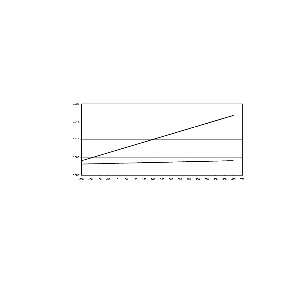
Checking the triple point of water probe resistance value (R0) and entering it into the
HP 34420A in effect relieves the meter of absolute gain accuracy requirements making
it simply a resistance ratio measuring device. Performing the triple point check will
therefore eliminate the 0.0015% of reading error producing an absolute temperature
accuracy of:
0.002
°C (for measurement) + 0.001 °C (for math) = ±0.003 °C
Using 0.0000% of reading error is valid within four hours of performing an R
instrument’s operating environment is stable to
C
°
Error
24-Hour Accuracy
Without R
Check
0
Temperature °C
±1 °C during the measurement period.
24-Hour Accuracy
With R
Check
0
check if the
0
Figure 1. SPRT total measurement error versus temperature before and
after checking the triple point of water probe resistance (R
).
0
6
Page 7

New Front-Panel Menu Entries
A new RTD type (USER SPRT) has been added within the TEMP MENU as shown below.
Select this entry to enable the HP 34420A to measure
. . . B: TEMP MENU . . .
SPRT transducers.
q
. . . 3: RTD TYPE . . .
q
ALPHA = .00385 ALPHA = .003916 USER SPRT
New Entry
After selecting “
TEMP MENU as shown below. The new entry is visible only after you select “USER SPRT”
USER SPRT”, a new entry (SPRT COEF) will appear on the top level of the
(see above).
. . . B: TEMP MENU . . .
q
. . . 6: COLD JUNCT 7: JUNCT TEMP 8: SPRT COEF
New Entry
q
Press
EDIT A4
Edit Number
EDIT B4
Edit Number
EDIT A7
Edit Number
EDIT B7
Edit Number
EDIT C7
Edit Number
You are automatically exited from
the menu upon completion.
Press
Press
Press
Press
Press
Press
Press
Press
Press
ENTER
ENTER
ENTER
ENTER
ENTER
ENTER
ENTER
ENTER
ENTER
ENTER
7
Page 8

When editing the numeric coefficients shown on the previous page, notice that an engineering
units multiplier is also available to edit beyond the smallest (right-most) digit. Multipliers
range from:
Tera
Giga
Megak
ilo
––
milli
micro
nano
pico
femto
New SCPI Commands for Remote Interface Programming
=
=
=
=
=
=
=
=
=
=
x10
x10
x10
x10
x1
x10
x10
x10
x10
x10
12
9
6
3
-3
-6
-9
-12
-15
In practice, the “micro” (x10-6 ) engineering
unit will be most convenient when entering
common ITS-90 calibration values.
New parameters are shown in bold.
[SENSe:]TEMPerature:
TRANsducer:FRTD:TYPE {85|91|USER}
CONFigure:TEMPerature
FRTD,{85|91|USER|DEF}[,1,{,<
resolution>|MIN|MAX|DEF}]
[SENSe:]TEMPerature:
TRANsducer:FRTD:USER:COEFficients {<A4>},{<B4>},{<A7>},{<B7>},{<C7>}
When using the above command, you must specify all five coefficients;
are not allowed. Data is stored as double-precision, 64-bit floating-point numbers.
default values
8
Page 9

Additional Temperature Measurement Commands
The HP 34420A commands for measuring temperature are shown below. Detailed
descriptions of these commands are included in the HP 34420A User’s Guide but the
syntax statements are repeated here for your convenience.
[SENSe:]TEMPerature:TRANsducer:TYPE {TCouple|THERmistor|FRTD}
[SENSe:]TEMPerature:TRANsducer:TYPE?
TEMPerature:TRANsducer:FRTD:RESistance[:REFerence] <
TEMPerature:TRANsducer:FRTD:RESistance[:REFerence]?
UNIT:TEMPerature {C|F|K}
UNIT:TEMPerature?
value>
9
Page 10

Part Number 34420-90091
January 1999
© Copyright Hewlett-Packard Company 1995, 1999
All Rights Reserved.
 Loading...