

Page 1

Operating and Service Guide
Agilent Technologies
Trueform Series
Waveform Generator
Page 2

Page 3

Agilent Trueform Series Waveform Generator
Operating and Service Guide
This document includes user, service, and programming information for the Agilent Trueform Series waveform
generators. For the latest firmware and documentation, see www.agilent.com/find/trueformhelp. The latest version of
the documentation is also available for mobile devices at www.agilent.com/find/trueformmobile.
You may also scan the following QR code with your smart phone or tablet to go to the mobile documentation.
For the latest datasheet with all specifications and typical characteristics, see
cp.literature.agilent.com/litweb/pdf/5991-3272EN.pdf.
Agilent welcomes your comments and suggestions to improve our documentation. You can give feedback on this
document at www.agilent.com/find/trueformdocfeedback.
Page 4

Agilent BenchVue Software
The Agilent Trueform Series waveform generators work with BenchVue software, which provides easy multiinstrument control. For more information, go to www.agilent.com/find/benchvue.
Use BenchVue to:
l View and control all of your bench instruments from a single screen
l Save/recall the state of your entire bench
l Acquire data and screenshots from multiple instruments
Save time with:
l Time aligned multi-instrument export to Excel, Word, MATLAB
l Export of waveform generator data to Word
l Drag and drop waveforms between your waveform generator and oscilloscope
l Integrated library capability for downloading instrument documentation, software drivers, firmware updates,
FAQs, videos, and more
From anywhere:
l Mobile companion apps to monitor and control your bench
2 Agilent Trueform Series Operating and Service Guide
Page 5

Preliminary Information
Safety and Regulatory Information
Models and Options
Maximum Waveform Frequencies by Model
Operating Information
Introduction to Instrument
Quick Start
Front Panel Menu Operation
Front Panel Menu Reference
LAN Configuration Procedure
Set Up Arbitrary Waveform
Features and Functions
Waveform Generation Tutorial
SCPI Programming Reference
Introduction to SCPI Language
Internal Function Waveforms
Alphabetical List of SCPI Commands and Queries
Programming Examples
Command Quick Reference
Factory Reset State
SCPI Error Messages
Agilent Trueform Series Operating and Service Guide 3
Page 6

Service and Repair Information
Service and Repair Introduction
Calibration and Adjustment: 33500 Series
Calibration and Adjustment: 33600 Series
Block Diagram - 33500 Series
Block Diagram - 33600 Series
Power Supplies - 33500 Series
Power Supplies - 33600 Series
Troubleshooting - 33500 Series
Troubleshooting - 33600 Series
Self-Test Procedures
Replaceable Parts
Disassembly - 33500 Series
Disassembly - 33600 Series
Battery Replacement
Installing the Optional GPIB Interface
IO Libraries and Instrument Drivers
The Agilent IO Libraries Suite software, including installation instructions, is on the Agilent IO Libraries Suite CD
provided with your instrument.
For information about connecting and configuring USB, LAN, and GPIB interfaces, refer to the Agilent USB/LAN/GPIB
Interfaces Connectivity Guide on the Agilent IO Libraries Suite CD, and at www.agilent.com/find/connectivity.
4 Agilent Trueform Series Operating and Service Guide
Page 7

Web Interface
The instrument includes a built-in Web Interface. You can use this interface over LAN for remote instrument access
and control via a Java™-enabled Web browser, such as Microsoft Internet Explorer.
To use the Web Interface:
1. Establish a LAN connection from your PC to the instrument.
2. Open your PC's Web browser.
3. Launch the instrument's Web Interface by entering the instrument's IP address or fully-qualified hostname in the
browser address field.
4. Follow the instructions in the Web Interface's on-line help.
Example Programs
There are several example programs on the product page Web site (www.agilent.com/find/trueform). These are
application-focused programs that demonstrate different programming environments. This document also includes
programming examples to help get you started.
Agilent Trueform Series Operating and Service Guide 5
Page 8

Contacting Agilent Technologies
You can contact Agilent Technologies for warranty, service, or technical support.
In the United States: (800) 829-4444
In Europe: 31 20 547 2111
In Japan: 0120-421-345
Use www.agilent.com/find/assist for information on contacting Agilent worldwide, or contact your Agilent Technologies
representative.
© Agilent Technologies, Inc. 2013
Version 1.0
December, 2013
6 Agilent Trueform Series Operating and Service Guide
Page 9

Safety and Regulatory Information
Safety and Regulatory Information
Notices
© Agilent Technologies, Inc. 2013
No part of this manual may be reproduced in any form or by any means (including electronic storage and retrieval or
translation into a foreign language) without prior agreement and written consent from Agilent Technologies, Inc. as
governed by United States and international copyright laws.
Manual Information
Part Number: 33500-90901
Manufacturer Address
Agilent Technologies, Inc.
900 S. Taft Ave.
Loveland, CO 80537 USA
Software and Documentation Updates and Licenses
Agilent releases software updates to fix defects and incorporate product enhancements. For the latest firmware and
documentation, see www.agilent.com/find/trueformhelp. The latest version of the documentation is also available for
mobile devices at www.agilent.com/find/trueformmobile.
A portion of the software in this product is licensed under terms of the General Public License Version 2 ("GPLv2"). The
text of the license and source code can be found at www.agilent.com/find/GPLV2.
This product uses Microsoft Windows CE. Agilent highly recommends that all Windows-based computers connected to
Windows CE instruments use current anti-virus software. For more information, see www.agilent.com/find/trueform.
Warranty
The material contained in this document is provided "as is," and is subject to being changed, without notice, in future
editions. Further, to the maximum extent permitted by applicable law, Agilent disclaims all warranties, either express
or implied, with regard to this manual and any information contained herein, including but not limited to the implied
warranties of merchantability and fitness for a particular purpose. Agilent shall not be liable for errors or for incidental or
consequential damages in connection with the furnishing, use, or performance of this document or of any information
contained herein. Should Agilent and the user have a separate written agreement with warranty terms covering the
material in this document that conflict with these terms, the warranty terms in the separate agreement shall control.
Technology Licenses
The hardware and/or software described in this document are furnished under a license and may be used or copied only
in accordance with the terms of such license.
Agilent Trueform Series Operating and Service Guide 7
Page 10

Safety and Regulatory Information
Restricted Rights Legend
If software is for use in the performance of a U.S. Government prime contract or subcontract, Software is delivered and
licensed as "Commercial computer software" as defined in DFAR 252.227-7014 (June 1995), or as a "commercial
item" as defined in FAR 2.101(a) or as "Restricted computer software" as defined in FAR 52.227-19 (June 1987) or any
equivalent agency regulation or contract clause. Use, duplication or disclosure of Software is subject to Agilent
Technologies’ standard commercial license terms, and non-DOD Departments and Agencies of the U.S. Government
will receive no greater than Restricted Rights as defined in FAR 52.227-19(c)(1-2) (June 1987). U.S. Government
users will receive no greater than Limited Rights as defined in FAR 52.227-14 (June 1987) or DFAR 252.227-7015 (b)
(2) (November 1995), as applicable in any technical data.
Safety Notices
A CAUTION notice denotes a hazard. It calls attention to an operating procedure, practice, or the like that, if not
correctly performed or adhered to, could result in damage to the product or loss of important data. Do not proceed
beyond a CAUTION notice until the indicated conditions are fully understood and met.
A WARNING notice denotes a hazard. It calls attention to an operating procedure, practice, or the like that, if not
correctly performed or adhered to, could result in personal injury or death. Do not proceed beyond a WARNING notice
until the indicated conditions are fully understood and met.
Safety Symbols
Alternating current
Frame or chassis terminal (functional ground)
Standby supply. Unit is not completely disconnected from AC mains when switch is
off.
Risk of electric shock
Refer to accompanying documents
Protective Earth ground terminal (safety ground)
8 Agilent Trueform Series Operating and Service Guide
Page 11

Safety and Regulatory Information
The CE mark is a registered trademark of the European Community.
The ETL mark is a registered trademark of Intertek. Applies to 33500 Series
instruments only.
The CSA mark with the 'c' and 'us' subscript indicates the instrument is certified to
the applicable Canadian and United States of America standards respectively. Applies
to 33600 Series instruments only.
The C-tick mark is a registered trademark of the Spectrum Management Agency of
Australia. This signifies compliance with the Australian EMC Framework regulations
under the terms of the Radio Communications Act of 1992.
Contains one or more of the 6 hazardous substances above the maximum
concentration value (MCV), 40 Year EPUP.
1SM 1-A This text indicates that the instrument is an Industrial Scientific and Medical Group 1
Class A product (CISPR 11, Clause 4).
ICES/NMB001
This ISM device complies with Canadian ICES-001.
Cet appareil ISM est conforme à la norme NMB-001 du Canada.
This product complies with the WEEE Directive (2002/96/EC) marking equipment.
The affixed product label indicates that you must not discard this electrical/electronic
product in domestic household waste.
To return unwanted products, contact your local Agilent office, or see
www.agilent.com/environment/product/ for more information.
This equipment is Class A suitable for professional use and is for use in
electromagnetic environments outside of the home.
Additional Safety Notices
The following general safety precautions must be observed during all phases of operation of this instrument. Failure to
comply with these precautions or with specific warnings or instructions elsewhere in this manual violates safety
standards of design, manufacture, and intended use of the instrument. Agilent Technologies assumes no liability of the
customer’s failure to comply with the requirements.
General
Do not use this product in any manner not specified by the manufacturer. The protective features of this product may
be impaired if it is used in a manner not specified in the operation instructions.
Agilent Trueform Series Operating and Service Guide 9
Page 12

Safety and Regulatory Information
Before Applying Power
Verify that all safety precautions are taken. Make all connections to the unit before applying power.
Ground the Instrument
This product is provided with protective earth terminals. To minimize shock hazard, the instrument must be connected
to the AC power mains through a grounded power cable, with the ground wire firmly connected to an electrical ground
(safety ground) at the power outlet. Any interruption of the protective (grounding) conductor or disconnection of the
protective earth terminal will cause a potential shock hazard that could result in personal injury.
l Do not operate in an explosive atmosphere.
l Do not operate the instrument in the presence of flammable gases or fumes.
l Only qualified, service-trained personnel who are aware of the hazards involved should remove instrument covers.
Always disconnect the power cable and any external circuits before removing the instrument cover.
Do Not Modify the Instrument
Do not install substitute parts or perform any unauthorized modification to the product. Return the product to an
Agilent Sales and Service Office for service and repair to ensure that safety features are maintained.
In Case of Damage
Instruments that appear damaged or defective should be made inoperative and secured against unintended operation
until they can be repaired by qualified service personnel.
Unless otherwise noted in the specifications, this instrument or system is intended for indoor use in an installation
category II, pollution degree 2 environment per IEC 61010-1 and 664 respectively. It is designed to operate at a
maximum relative humidity of 5% to 80% at 40 °C or less (non-condensing). This instrument or system is designed to
operate at altitudes up to 3000 meters, and at temperatures between 0 and 55 °C.
Technical Support
If you have questions about your shipment, or if you need information about warranty, service, or technical support,
contact Agilent Technologies.
10 Agilent Trueform Series Operating and Service Guide
Page 13

Models and Options
Models and Options
This section describes the models and options in the Trueform Series of instruments. For information on loading
licenses for options via the front panel, see License Installation. For information on loading licenses via SCPI, see the
SYSTem:LICense commands.
Instrument Models
Instrument models with numbers of the form 335XXA or 335XXB are referred to as the 33500 Series, and instrument
models with numbers of the form 336XXA are referred to as the 33600 Series. Collectively, the 33500 Series and
33600 Series instruments comprise the Trueform Series of waveform generators. Unless specified otherwise, all
manual topics apply to all instruments in the Trueform Series.
To determine the model number of your instrument, read the label on the instrument's front panel. You can also either
execute the *IDN? query over the remote interface or press [System] >Help > About on the front panel.
The Trueform Series model numbers and option numbers are shown and described in the table below.
Model Description Options
33521A 30 MHz
One channel
Arbitrary waveforms
NISPOM Security
1 MSa Memory per channel
33522A 30 MHz
Two channels
Arbitrary waveforms
NISPOM Security
1 MSa memory per channel
33509B 20 MHz
One channel
No arbitrary waveforms
33510B 20 MHz
Two channels
No arbitrary waveforms
33511B 20 MHz
One channel
Arbitrary waveforms
33512B 20 MHz
Two channels
Arbitrary waveforms
002 - 16MSa Arb Memory
004 - GPIBInterface
010 - High-stability OCXO Timebase
002 - 16MSa Arb Memory
004 - GPIBInterface
010 - High-stability OCXO Timebase
OCX - Add High-stability OCXO Timebase
SEC - Enable NISPOM & File Security
OCX - Add High-stability OCXO Timebase
SEC - Enable NISPOM & File Security
MEM - 16 MSa Memory per channel
OCX - Add High-stability OCXO Timebase
SEC - Enable NISPOM & File Security
MEM - 16 MSa Memory per channel
OCX - Add High-stability OCXO Timebase
SEC - Enable NISPOM & File Security
IQP - Add IQ Baseband signal player
33519B 30 MHz
One channel
No arbitrary waveforms
Agilent Trueform Series Operating and Service Guide 11
OCX - Add High-stability OCXO Timebase
SEC - Enable NISPOM & File Security
Page 14

Models and Options
Model Description Options
33520B 30 MHz
Two channels
No arbitrary waveforms
33521B 30 MHz
One channel
Arbitrary waveforms
33522B 30 MHz
Two channels
Arbitrary waveforms
33611A 80 MHz
One channel
Arbitrary waveforms
33612A 80 MHz
Two channels
Arbitrary waveforms
33621A 120 MHz
One channel
Arbitrary waveforms
OCX - Add High-stability OCXO Timebase
SEC - Enable NISPOM & File Security
MEM - 16 MSa Memory per channel
OCX - Add High-stability OCXO Timebase
SEC - Enable NISPOM & File Security
MEM - 16 MSa Memory per channel
OCX - Add High-stability OCXO Timebase
SEC - Enable NISPOM & File Security
IQP - Add IQ Baseband signal player
MEM - 64 MSa Memory per channel
OCX - Add High-stability OCXO Timebase
SEC - Enable NISPOM & File Security
MEM - 64 MSa Memory per channel
OCX - Add High-stability OCXO Timebase
SEC - Enable NISPOM & File Security
IQP - Add IQ Baseband signal player
MEM - 64 MSa Memory per channel
OCX - Add High-stability OCXO Timebase
SEC - Enable NISPOM & File Security
GPB - GPIB interface module – factory installed
33622A 120 MHz
Two channels
Arbitrary waveforms
MEM - 64 MSa Memory per channel
OCX - Add High-stability OCXO Timebase
SEC - Enable NISPOM & File Security
IQP - Add IQ Baseband signal player
GPB - GPIB interface module – factory installed
12 Agilent Trueform Series Operating and Service Guide
Page 15

One- and two-channel upgrades for 33500 Series
Model Description
335BW1U Increase bandwidth to 30 MHz for one-channel models
335BW2U Increase bandwidth to 30 MHz for two-channel models
335ARB1U Add arbitrary waveforms to one-channel models
335ARB2U Add arbitrary waveforms to two-channel models
335MEM1U 16 MSa per channel memory for one-channel models
335MEM2U 16 MSa per channel memory for two-channel models
33500U-OCX Add high-stability OCXO timebase
335SECU Add NISPOMand File security
335IQPU Add IQ Baseband signal player
Models and Options
33522B-DST Enable all software options for demonstration
One- and two-channel upgrades for 33600 Series
Model Description
336BW1U Increase bandwidth to 120 MHz for one-channel models
336BW2U Increase bandwidth to 120 MHz for two-channel models
336MEM1U 64 MSa per channel memory for one-channel models
336MEM2U 64 MSa per channel memory for two-channel models
33600U-OCX Add high-stability OCXO timebase
336SECU Add NISPOMand File security
336IQPU Add IQ Baseband signal player
33622A-DST Enable all software options for demonstration
3446GPBU GPIB user installable interface module
Agilent Trueform Series Operating and Service Guide 13
Page 16

Maximum Waveform Frequencies by Model
Maximum Waveform Frequencies by Model
33500 Series, Lower Frequency Models
33509B 33510B 33511B 33512B
Waveform Maximum Frequency
Sine 20 MHz
Square/Pulse 20 MHz
Noise 20 MHz
Ramp/Triangle 200 kHz
PRBS 50 Mbps
Arbitrary 160 MSa/s
33500 Series, Higher Frequency Models
33521A 33522A 33519B 33520B 33521B 33522B or other 33500 Series models with option
335BW1U or 335BW2U.
Waveform Maximum Frequency
Sine 30 MHz
Square/Pulse 30 MHz
Noise 30 MHz
Ramp/Triangle 200 kHz
PRBS 50 Mbps
Arbitrary 250 MSa/s
14 Agilent Trueform Series Operating and Service Guide
Page 17

33600 Series, Lower Frequency Models
33611A 33612A
Waveform Maximum Frequency
Sine 60 MHz up to 10 Vpp
80 MHz up to 8 Vpp
Square/Pulse 50 MHz up to 10 Vpp
Noise 60 MHz up to 10 Vpp
80 MHz up to 8 Vpp
Ramp/Triangle 800 kHz
PRBS 100 Mbps
Arbitrary 660 MSa/s
Maximum Waveform Frequencies by Model
33600 Series, Higher Frequency Models
33621A 33622A or other 33600 Series models with option 336BW1U or 336BW2U.
Waveform Maximum Frequency
Sine 60 MHz up to 10 Vpp
80 MHz up to 8 Vpp
120 MHz up to 4 Vpp
Square/Pulse 50 MHz up to 10 Vpp
100 MHz up to 4 Vpp
Noise 60 MHz up to 10 Vpp
80 MHz up to 8 Vpp
120 MHz up to 4 Vpp
Ramp/Triangle 800 kHz
PRBS 100 Mbps up to 10 Vpp
200 Mbps up to 4 Vpp
Arbitrary 1 GSa/s
Agilent Trueform Series Operating and Service Guide 15
Page 18

Operating Information
Operating Information
Introduction to Instrument
Quick Start
Front Panel Menu Operation
Front Panel Menu Reference
LAN Configuration Procedure
Set Up Arbitrary Waveform
Features and Functions
Waveform Generation Tutorial
16 Agilent Trueform Series Operating and Service Guide
Page 19

Introduction to Instrument
Introduction to Instrument
The Agilent Technologies Trueform Series is a series of synthesized waveform generators with built-in arbitrary
waveform and pulse capabilities.
Instrument at a Glance
Front Panel at a Glance
Front Panel Display at a Glance
Front Panel Number Entry
Rear Panel at a Glance
Instrument at a Glance
The instrument's combination of bench-top and system features makes it a versatile solution now and in the future.
Convenient bench-top features
l 16 standard waveforms
l Built-in 16-bit (33500 Series) or 14-bit (33600 Series) arbitrary waveform capability
l Precise pulse waveform capabilities with adjustable edge time
l LCD display with numeric and graphical views
l Easy-to-use knob and numeric keypad
l Instrument state storage with user-defined names
l Portable, ruggedized case with non-skid feet
l Isolated outputs to break ground loops
Flexible system features
l Downloadable waveform memory of 1MSa (33500 Series) or 4 MSa (33600 Series). This can be upgraded to 16
MSa (33500 Series) or 64 MSa (33600 Series).
l USB, GPIB, and LAN remote interfaces (GPIB is optional on some models; see Models and Options for details.)
l LXI Class C Compliant
l SCPI (Standard Commands for Programmable Instruments) compatibility
Agilent Trueform Series Operating and Service Guide 17
Page 20

Introduction to Instrument
Front Panel at a Glance
The BNC connectors, both the shell and center pin, on the front panel of the instrument are isolated up
to ±42 Vpk from chassis. The shells of these BNC connectors are connected to each other, and internal
circuitry will attempt to keep the isolated voltage to within ±42 Vpk to chassis. Exceeding the isolation
voltage beyond ±42 Vpk from chassis may destroy the instrument and cause a hazard that could result
in personal injury or death.
Item Description
1 USB Port
2 On/Off Standby Switch
3 Display
4 Menu Softkeys
5 Fixed Function Buttons
(column of seven keys)
6 Manual Trigger Button
7 Sync Connector
8 Numeric Keypad
9 Channel 1 and Channel 2
(depending on model)
10 Knob and cursor arrows
Press and hold any front panel key or softkey to get context-sensitive help.
18 Agilent Trueform Series Operating and Service Guide
Page 21

Front Panel Display at a Glance
Item Description
1 Channel 1 information
2 Channel 2 information (depends on model)
Introduction to Instrument
3 Waveform parameters
4 Waveform display
5 Sweep, modulation, or burst parameters
6 Softkey labels
Agilent Trueform Series Operating and Service Guide 19
Page 22

Introduction to Instrument
Front Panel Number Entry
You can enter numbers from the front panel in two ways:
l Use the knob and cursor keys to modify the number. Rotate the knob to change a digit (clockwise increases). The
arrows below the knob move the cursor.
l Use the keypad to enter numbers and the softkeys to select units. The [+/-] key changes the number's sign.
20 Agilent Trueform Series Operating and Service Guide
Page 23

Introduction to Instrument
Rear Panel at a Glance
The rear panels on the 33500 Series and 33600 Series instruments have similar features, but their locations vary, as
shown below.
33500 Series
33600 Series
Item Description
1 External 10 MHz Reference Input
2 Internal 10 MHz Reference Output
3 GPIB Connector
4 Chassis Ground
Agilent Trueform Series Operating and Service Guide 21
Page 24

Introduction to Instrument
Item Description
5 Instrument Cable Lock
6 AC Power
7 External Modulation Input
8 External Trig/Gate/FSK/Burst (Input and Output)
9 USB Interface Connector
10 Local Area Network (LAN) Connector
The external 10 MHz reference input BNC connector, both the shell and center pin, on the rear panel of
the instrument is isolated up to ±42 Vpk from chassis. The shell of this BNC connector is isolated from
the rest of the instrument. Internal circuitry will attempt to keep the isolated voltage to within ±42
Vpk to chassis. Attempts to float this input beyond ±42 Vpk from chassis may destroy the instrument
and cause a hazard that could result in personal injury or death.
The external modulation input BNC connector, both the shell and center pin, on the rear panel of the
instrument is isolated up to ±42 Vpk from chassis. The shell of this BNC connector is connected to the
shells of the front panel BNC connectors. Internal circuitry will attempt to keep the isolated voltage to
within ±42 Vpk to chassis. Attempts to float the outputs beyond ±42 Vpk from chassis may destroy
the instrument and cause a hazard that could result in personal injury or death.
This is a Protection Class 1 equipment (chassis must be connected to a protective earth ground).
The mains plug shall only be inserted in an outlet provided with a Protective Earth Terminal.
22 Agilent Trueform Series Operating and Service Guide
Page 25

Quick Start
This section describes basic procedures to help you get started quickly with the instrument.
l Prepare Instrument for Use
l Adjust the Carrying Handle
l Set Output Frequency
l Set Output Amplitude
l Set DC Offset Voltage
l Set High-Level and Low-Level Values
l Output a DC Voltage
l Set Duty Cycle of a Square Wave
l Configure a Pulse Waveform
l Select a Stored Arbitrary Waveform
l Use Built-in Help System
l Rack Mount the Instrument
Quick Start
Agilent Trueform Series Operating and Service Guide 23
Page 26

Quick Start
Prepare Instrument for Use
Verify that you received the following items. If anything is missing, please contact your nearest Agilent sales office or
Agilent authorized reseller.
l Power cord (for country of destination)
l Certificate of Calibration
l Agilent Trueform Series Product Reference CD (product software, programming examples, and
manuals)
l Agilent IO Libraries Suite CD
l USB 2.0 cable
Note: All product documentation is on the Agilent Trueform Series Product Reference CD. For the
latest firmware and documentation, see www.agilent.com/find/trueformhelp. The latest version of
the documentation is also available for mobile devices at www.agilent.com/find/trueformmobile.
You may also scan the following QR code with your smart phone or tablet to go to the mobile
documentation.
The instrument may be used with mains power of either 100-240 V, 50/60 Hz or 100-120 V, 400 Hz. The maximum
power usage is 150 VA. Ensure that you are using the correctly rated mains cord based on the instrument’s rating and
your country's electrical codes. Connect the power cord and LAN, GPIB, or USB cable as desired. Turn the instrument
on by pressing the power switch in the lower left corner of front panel. The instrument runs a power-on self test and
then displays a message about how to obtain help, along with the current IP address. It also displays the GPIB address if
the GPIB option is installed and enabled.
PowerSwitch:
The instrument's default function is a 1 kHz, 100 mVpp sine wave (into a 50 Ω termination). At power-on, the channel
output connectors are disabled. To enable output on a channel connector, press the key above the channel connector
and then press the Output Off / On softkey.
If the instrument does not turn on, verify that the power cord is firmly connected. Also make sure that the instrument
is connected to an energized power source. If the LED below the power switch is off, there is no AC power connected. If
the LED is amber, the instrument is in standby mode with AC power connected, and if it is green, the instrument is on.
24 Agilent Trueform Series Operating and Service Guide
Page 27

Quick Start
If the power-on self test fails, the display shows ERR in the upper right corner. It also prominently displays "Check for
error messages in the error queue."
See SCPI Error Messages for information on error codes. See Service and Repair - Introduction for instructions on
returning the instrument for service.
To turn off the instrument, hold the power switch down for about 500 ms. This prevents you from turning the
instrument off by accidentally brushing the power switch.
Adjust the Carrying Handle
Grasp the sides of the handle, pull outward, and rotate the handle.
Agilent Trueform Series Operating and Service Guide 25
Page 28

Quick Start
Set Output Frequency
The default frequency is 1 kHz. You can change the frequency, and you can specify frequency in units of period instead
of Hz.
To change frequency with the knob:
To change frequency with the numeric keypad:
Finish by selecting frequency units:
To change the units to period instead of frequency:
26 Agilent Trueform Series Operating and Service Guide
Page 29

Set Output Amplitude
The instrument's default function is a 1 kHz, 100 mVpp sine wave (into a 50 Ω termination).
The following steps change the amplitude to 50 mVpp.
1. Press [Units] > Amp/Offs or High/Low to make sure that you are in Amp/Offs.
The displayed amplitude is either the power-on value or the amplitude previously selected. When you change
functions, the same amplitude is used if it is valid for the new function. To choose whether you want to specify
voltage as amplitude and offset or high and low values, press [Units] and then the second softkey. In this case,
we will highlight Amp/Offs.
Quick Start
2. Enter the magnitude of the desired amplitude.
Press [Parameters] > Amplitude. Using the numeric keypad, enter the number 50.
3. Select the desired units.
Press the softkey that corresponds to the desired units. When you select the units, the instrument outputs the
waveform with the displayed amplitude (if the output is enabled). For this example, press mVpp.
You can also enter the desired value using the knob and arrows. If you do so, you do not need to use a units
softkey. You can easily convert unit types. Simply press [Units] > Ampl As and select the desired units.
Agilent Trueform Series Operating and Service Guide 27
Page 30

Quick Start
Set DC Offset Voltage
At power-on, the DC offset is 0 V. The following steps change the offset to –1.5 VDC.
1. Press [Parameters] > Offset.
The displayed offset voltage is either the power-on value or the offset previously selected. When you change
functions, the same offset is used if the present value is valid for the new function.
2. Enter the desired offset.
In this case we will use the numeric keypad to enter –1.5.
3. Select the desired units.
Press the softkey for the desired units. When you select the units, the instrument outputs the waveform with the
displayed offset (if the output is enabled). For this example, press V. The voltage will be set as shown below.
You can also enter the desired value using the knob and arrows.
28 Agilent Trueform Series Operating and Service Guide
Page 31

Quick Start
Set High-Level and Low-Level Values
You can specify a signal by setting its amplitude and DC offset, described above. You can also specify the signal as high
(maximum) and low (minimum) values. This is typically convenient for digital applications. In the following example,
we will set the high level to 1.0 V and the low level to 0.0 V.
1. Press [Units] > Ampl/Offs to toggle to High/Low as shown below.
2. Press the [Parameters] > High Level. Using the numeric keypad or knob and arrows, select a value of 1.0 V. (If
you are using the keypad, you will need to select the V unit softkey to enter the value.)
3. Press the Low Level softkey and set the value.
Again, use the numeric keypad or the knob to enter a value of 0.0 V.
These settings (high-level = 1.0 V and low-level = 0.0 V) are equivalent to setting an amplitude of 1.0 Vpp and an
offset of 500 mV.
Agilent Trueform Series Operating and Service Guide 29
Page 32

Quick Start
Output a DC Voltage
You can output a constant DC voltage, from -5 V to +5 V into 50 Ω, or -10 V to +10 V into a high impedance load.
1. Press [Waveforms] > More > DC.
The Offset value becomes selected.
2. Enter the desired voltage offset.
Enter 1.0 with the numeric keypad or knob, and press the V softkey if you used the keypad.
30 Agilent Trueform Series Operating and Service Guide
Page 33
Quick Start
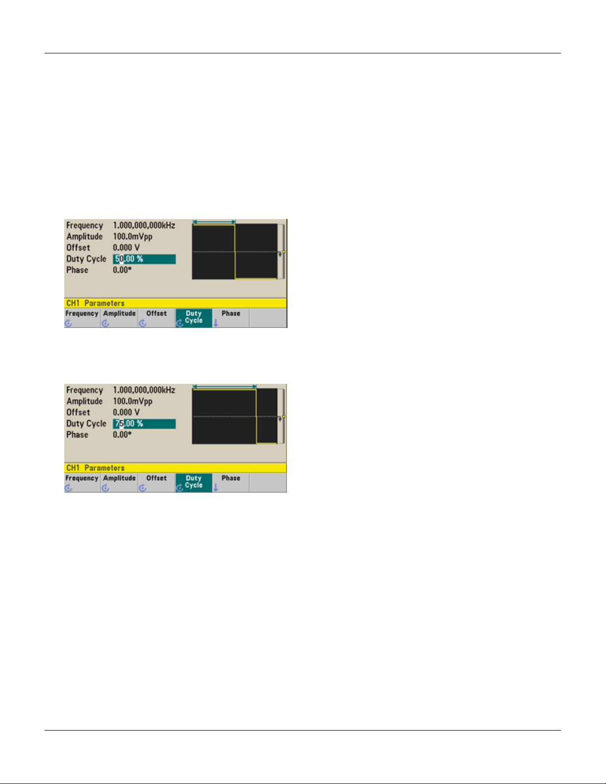
Set Duty Cycle of a Square Wave
The power-on default for square wave duty cycle is 50%. The duty cycle is limited by the minimum pulse width
specification of 16 ns on the 33500 Series, or 5 ns up to 4 Vpp and 8 ns up to 10 Vpp on the 33600 Series. The
following procedure changes the duty cycle to 75%.
1. Select the square wave function.
Press [Waveforms] > Square.
2. Press the Duty Cycle softkey.
The displayed duty cycle is either the power-on value or the percentage previously selected. The duty cycle
represents the amount of time per cycle that the square wave is at a high level.
3. Enter the desired duty cycle.
Using the numeric keypad or the knob and arrows, select a duty cycle value of 75. If you are using the numeric
keypad, press Percent to finish the entry. The instrument adjusts the duty cycle immediately and outputs a
square wave with the specified value (if the output is enabled).
Agilent Trueform Series Operating and Service Guide 31
Page 34

Quick Start
Configure a Pulse Waveform
You can configure the instrument to output a pulse waveform with variable pulse width and edge time. The following
steps configure a 500 ms periodic pulse waveform with a pulse width of 10 ms and edge times of 50 ns.
1. Select the pulse function.
Press [Waveforms] > Pulse to select the pulse function.
2. Set the pulse period.
Press the [Units] key and then press Frequency/Period to choose Period. Then press [Parameters]
>Period. Set the period to 500 ms.
3. Set the pulse width.
Press [Parameters] >Pulse Width. Then set the pulse width to 10 ms. The pulse width represents the time
from the 50% threshold of the rising edge to the 50% threshold of the next falling edge.
4. Set the edge time for both edges.
Press the Edge Times softkey and then set the edge time for both the leading and trailing edges to 50 ns. The
edge time represents the time from the 10% threshold to the 90% threshold of each edge.
32 Agilent Trueform Series Operating and Service Guide
Page 35

Quick Start
Select a Stored Arbitrary Waveform
There are nine built-in arbitrary waveforms stored in non-volatile memory. They are Cardiac, D-Lorentz, Exponential
Fall, Exponential Rise, Gaussian, Haversine, Lorentz, Negative Ramp, and Sinc.
This procedure selects the built-in "exponential fall" waveform from the front panel. For information on creating a
custom arbitrary waveform, refer to Set Up Arbitrary Waveform.
1. Press [Waveforms] >Arb > Arbs.
2. Choose Select Arb and use the knob to select Exp_Fall. Press Select.
Agilent Trueform Series Operating and Service Guide 33
Page 36

Quick Start
Use Built-in Help System
The built-in help system provides context-sensitive help on any front panel key or menu softkey. A list of help topics is
also available to assist you with several front panel operations.
View the help information for a function key
Press and hold any softkey or front panel key, such as [Waveforms]. If the message contains more information than
will fit on the display, press the down arrow softkey or use the knob to view the remaining information.
Press Done to exit Help.
View the list of help topics.
Press [System] > Help to view the list of available help topics. To scroll through the list, press the up and down arrow
softkeys or use the knob. Select the topic Get HELP on any key and then press Select. Note that the topics may
vary from the list shown below, depending on model and firmware version.
Press Done to exit Help.
34 Agilent Trueform Series Operating and Service Guide
Page 37

Quick Start
View the help information for displayed messages.
Whenever a limit is exceeded or any other invalid configuration is found, the instrument displays a message. The builtin help system provides additional information on the most recent message. Press [System] > Help. Then select the
topic View the last message displayed, and press Select.
Press Done to exit Help.
Local Language Help
All messages, context-sensitive help, and help topics are available in English, Chinese, French,
German, Japanese, Korean, and Russian. Softkey labels and status line messages are not
translated. To select the language, press [System] > System Setup > User Settings
>HelpLang. Then select the desired language.
Agilent Trueform Series Operating and Service Guide 35
Page 38

Quick Start
Rack Mount the Instrument
You can mount the instrument in a standard 19-inch rack cabinet using one of two optional kits, each of which includes
instructions and mounting hardware. Any Agilent System II instrument of the same size can be rack-mounted beside
the instrument.
Remove the carrying handle, and the front and rear rubber bumpers, before rack-mounting the
instrument.
To remove the handle, rotate it to vertical and pull the ends outward.
To remove the rubber bumper, stretch a corner and then slide it off.
Front Rear (bottom view)
To rack mount a single instrument, order adapter kit 5063-9240.
To rack mount two instruments side-by-side, order lock-link kit 5061-8769 and flange kit 5063-9212.
Be sure to use the support rails in the rack cabinet.
To prevent overheating, do not block airflow to or from the instrument. Air enters at the rear of the
instrument and exits at both sides and the bottom. Ensure that at least one side is unblocked to
allow the ventilation air to exhaust freely. Do not block the fan on the instrument rear panel.
The 33600 Series instrument's fan speed runs at a constant speed up to an ambient temperature
of 28 °C and increases when the ambient temperature goes above 28 °C.
The 33600 Series instruments monitor critical internal temperatures and will shut down if limits
are exceeded. Failure of ventilation could result in shutdown.
36 Agilent Trueform Series Operating and Service Guide
Page 39

Front Panel Menu Operation
Front Panel Menu Operation
This section introduces front panel keys and menus. See Features and Functions, Front Panel Menu Reference, LAN
Configuration Procedure, and Set Up an Arbitrary Waveform for additional front panel operation information.
l Select Output Termination
l Reset the Instrument
l Output a Modulated Waveform
l Output an FSK Waveform
l Output a PWM Waveform
l Output a Frequency Sweep
l Output a Burst Waveform
l Trigger a Sweep or Burst
l Store or Retrieve the Instrument State
Select Output Termination
The instrument has a fixed series output impedance of 50 Ω to the front panel channel connectors. If the actual load
impedance differs from the value specified, the displayed amplitude and offset levels will be incorrect. The load
impedance setting is simply a convenience to ensure that the displayed voltage matches the expected load.
1. Press a channel output key to open the channel configuration screen. Note that the current output termination
values (both 50 Ω in this case) appear on the tabs at the top of the screen.
2. Begin specifying the output termination by pressing Output Load.
3. Select the desired output termination either by using the knob or numeric keypad to select the desired load
impedance or by pressing Set to 50 Ω or Set to High Z.
Reset the Instrument
To reset the instrument to its factory default state, press [System] > Set to Defaults >Yes.
Agilent Trueform Series Operating and Service Guide 37
Page 40

Front Panel Menu Operation
Output a Modulated Waveform
A modulated waveform consists of a carrier waveform and a modulating waveform. In AM (amplitude modulation), the
carrier amplitude is varied by the modulating waveform. For this example, you will output an AM waveform with 80%
modulation depth. The carrier will be a 5 kHz sine wave and the modulating waveform will be a 200 Hz sine wave.
1. Select the function, frequency, and carrier amplitude.
Press [Waveforms] >Sine. Press the Frequency, Amplitude, and Offset softkeys to configure the carrier
waveform. For this example, select a 5 kHz sine wave with an amplitude of 5 Vpp, with 0 V offset.
Note that you may specify amplitude in Vpp, Vrms or dBm.
2. Select AM.
Press [Modulate] and then select AM using the Type softkey. Then press the Modulate softkey to turn
modulation on. Notice that the [Modulate] key is illuminated, and the status message "AM Modulated by Sine"
appears at the top left of the display.
3. Set the modulation depth.
Press the AM Depth softkey and then set the value to 80% using the numeric keypad or the knob and arrows.
4. Select the modulating waveform shape.
Press Shape to select the modulating waveform's shape. For this example, select a sine wave.
5. Press AM Freq. On the 33500 Series, you will first have to press the More softkey to get to the correct menu. Set
the value to 200 Hz using the numeric keypad or the knob and arrows. Press Hz to finish entering the number if
you are using the numeric keypad.
38 Agilent Trueform Series Operating and Service Guide
Page 41
Front Panel Menu Operation
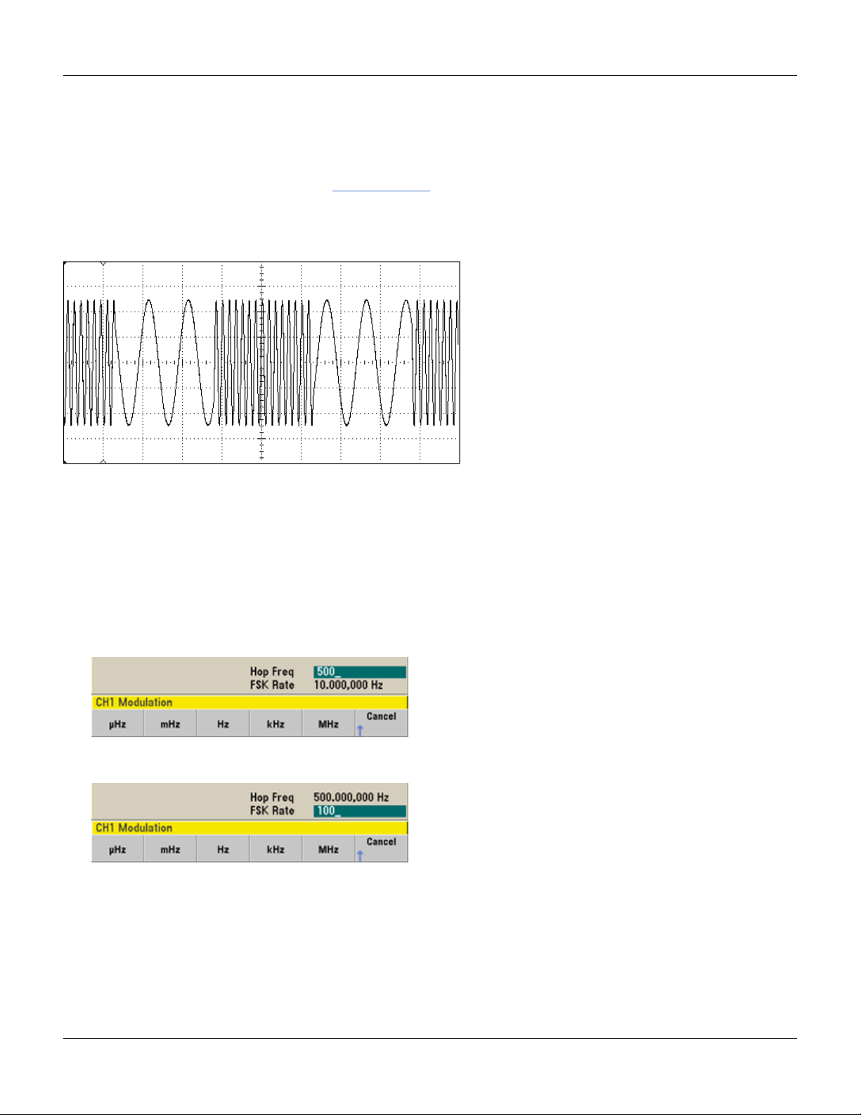
Output an FSK Waveform
You can configure the instrument to "shift" its output frequency between two preset values (called the "carrier
frequency" and the "hop frequency") using FSK modulation. The rate at which the output shifts between these two
frequencies is determined by the internal rate generator or the signal level on the rear-panel Ext Trig connector. For
this example, you will set the "carrier" frequency to 5 kHz and the "hop" frequency to 500 Hz, with an FSK rate of
100Hz.
1. Select the function, frequency, and carrier amplitude.
Press [Waveforms] >Sine. Press the Frequency, Amplitude, and Offset softkeys to configure the carrier
waveform. For this example, select a 5 kHz sine wave with an amplitude of 5 Vpp, with 0 V offset.
2. Select FSK.
Press [Modulate] and then select FSK using the Type softkey. Then press the Modulate softkey to turn
modulation on. Notice the status message "FSK Modulated" at the top left of the display.
3. Set the "hop" frequency.
Press the Hop Freq softkey and then set the value to 500 Hz using the numeric keypad or the knob and arrows. If
you use the numeric keypad, be sure to finish the entry by pressing Hz.
4. Set the FSK "shift" rate.
Press the FSK Rate softkey and then set the value to 100 Hz using the numeric keypad or the knob and arrows.
At this point, the instrument outputs an FSK waveform if the channel output is enabled.
Agilent Trueform Series Operating and Service Guide 39
Page 42

Front Panel Menu Operation
Output a PWM Waveform
You can configure the instrument to output a pulse width modulated (PWM) waveform. PWM is only available for the
Pulse waveform, and the pulse width varies according to the modulating signal. The amount by which the pulse width
varies is called the width deviation, and it can be specified as a percentage of the waveform period (that is, duty cycle)
or in units of time. For example, if you specify a pulse with 20% duty cycle and then enable PWM with a 5% deviation,
the duty cycle varies from 15% to 25% under control of the modulating signal.
To change from pulse width to pulse duty cycle, press [Units].
For this example, you will specify a pulse width and pulse width deviation for a 1 kHz pulse waveform with a 5-Hz sine
wave modulating waveform.
1. Select the carrier waveform parameters.
Press [Waveforms] > Pulse. Use the Frequency, Amplitude, Offset, Pulse Width and Edge Times
softkeys to configure the carrier waveform. For this example, select a 1 kHz pulse waveform with an amplitude of 1
Vpp, zero offset, a pulse width of 100 µs, and an edge time of 50 ns (both leading and trailing).
2. Select PWM.
Press [Modulate] > Type > PWM. Then press the first softkey (Modulate) to turn modulation on. Notice the
status message "PWM Modulated by Sine" in the upper-left corner of the display.
3. Set the width deviation.
Press the Width Dev softkey and set the value to 20 µs using the numeric keypad or the knob and arrows.
40 Agilent Trueform Series Operating and Service Guide
Page 43

Front Panel Menu Operation
4. Set the modulating frequency.
Press the PWM Freq softkey and then set the value to 5 Hz using the numeric keypad or the knob and arrows.
5. Select the modulating waveform shape.
Press Shape to select the modulating waveform's shape. For this example, select a sine wave.
To view the actual PWM waveform, you would need to output it to an oscilloscope. If you do this, you will see how the
pulse width varies, in this case, from 80 to 120 µs. At a modulation frequency of 5 Hz, the deviation is easily visible.
Agilent Trueform Series Operating and Service Guide 41
Page 44
Front Panel Menu Operation
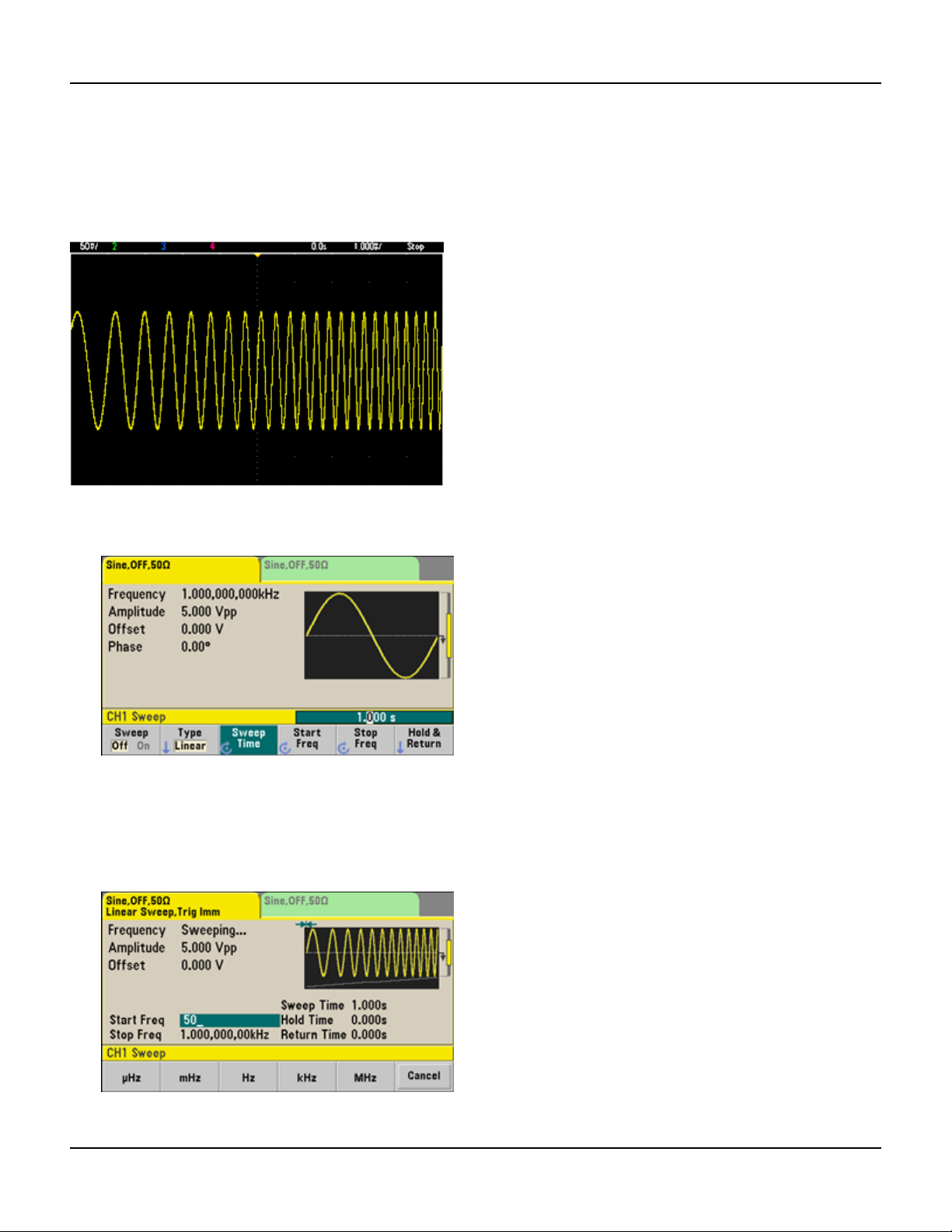
Output a Frequency Sweep
In the frequency sweep mode, the instrument moves from the start frequency to the stop frequency at a sweep rate,
which you specify. You can sweep up or down in frequency, and with either linear or logarithmic spacing, or using a list
of frequencies. For this example, you will output a swept sine wave from 50 Hz to 5 kHz.
1. Select the function and amplitude for the sweep.
For sweeps, you can select sine, square, ramp, pulse, triangle, PRBS waveforms, or arbitrary waveforms (noise and
DC are not allowed). For this example, select a sine wave with an amplitude of 5 Vpp.
2. Select the sweep mode.
Press [Sweep] and verify that the linear sweep mode is currently selected on the second softkey. Press the
Sweep softkey to turn sweep on. Notice the Linear Sweep status message at the top of the tab for the current
channel. The button is also illuminated.
3. Set the start frequency.
Press Start Freq and then set the value to 50 Hz using the numeric keypad or the knob and arrows.
42 Agilent Trueform Series Operating and Service Guide
Page 45

Front Panel Menu Operation
4. Set the stop frequency.
Press Stop Freq and set the value to 5 kHz using the numeric keypad or the knob and arrows.
At this point, the instrument outputs a continuous sweep from 50 Hz to 5 kHz if output is enabled.
You can also set the sweep frequency boundaries of the sweep using a center frequency and frequency span. These
parameters are similar to the start frequency and stop frequency (above) and they provide added flexibility. To achieve
the same results, set the center frequency to 2.525 kHz and the frequency span to 4.950 kHz.
To generate a frequency sweep, press [Trigger] twice. The first press puts the trigger in manual mode, and the second
one sends a trigger. For more information, see Trigger Sweep or Burst.
Agilent Trueform Series Operating and Service Guide 43
Page 46

Front Panel Menu Operation
Output a Burst Waveform
You can configure the instrument to output a waveform with for a specified number of cycles, called a burst. You can
control the amount of time that elapses between bursts with the internal timer or the signal level on the rear-panel Ext
Trig connector. For this example, you will output a three-cycle sine wave with a 20 ms burst period.
1. Select the function and amplitude for the burst.
For burst waveforms, you can select sine, square, ramp, pulse, arbitrary waveforms, triangle, or PRBS. Noise is
allowed only in the "gated" burst mode and DC is not allowed. For this example, select a sine wave with an
amplitude of 5 Vpp.
2. Select the burst mode.
Press [Burst] > Burst Off/On. Notice that a status message N Cycle Burst, Trig Imm is shown in the tab of
the current channel.
44 Agilent Trueform Series Operating and Service Guide
Page 47

Front Panel Menu Operation
3. Set the burst count.
Press # of Cycles and set the count to "3" using the numeric keypad or knob. Press Enter to finish data entry if
you are using the numeric keypad.
4. Set the burst period.
Press Burst Period and set the period to 20 ms using the numeric keypad or the knob and arrows. The burst
period sets the time from the start of one burst to the start of the next burst. At this point, the instrument outputs
a continuous three-cycle burst at 20 ms intervals.
You can generate a single burst (with the specified count) by pressing the [Trigger] key. For more information, see
Trigger Sweep or Burst.
You can also use the external gate signal to create gated bursts, where a burst is produced while a gate signal is present
on the input.
Trigger a Sweep or Burst
You can select one of four different types of triggers from the front panel for sweeps and bursts:
l Immediate or "automatic" (default): instrument outputs continuously when sweep or burst mode is selected.
l External: triggering controlled by rear panel Ext Trig connector.
l Manual: initiates one sweep or burst each time you press [Trigger]. Continue pressing [Trigger] to re-trigger
instrument.
l Timer: issues one or more triggers a fixed time amount apart.
If sweep or burst is on, pressing [Trigger] displays the trigger menu. An illuminated [Trigger] key (solid or blinking)
indicates that one or both channels are awaiting a manual trigger. Solid illumination occurs when the trigger menu is
selected, and flashing illumination occurs when the trigger menu is not selected. The [Trigger] key is disabled when
the instrument is in remote.
Pressing [Trigger] when it is solidly illuminated causes a manual trigger. Pressing [Trigger] when it is flashing selects
the trigger menu; a second press causes a manual trigger.
Agilent Trueform Series Operating and Service Guide 45
Page 48

Front Panel Menu Operation
Store or Retrieve the Instrument State
You can store instrument states in any number of state files, (extension .sta). You can do this for backup purposes, or
you can save your state to a USB drive and load it on another instrument to have instruments with matching
configurations. A stored state contains the selected function, frequency, amplitude, DC offset, duty cycle, symmetry,
and any modulation or burst parameters in use. The instrument does not store volatile arbitrary waveforms.
1. Select the desired storage location.
2. Press Name and specify the name for the selected location.
33500 Series
To add characters, press the right-cursor key until the cursor is to the right of the existing name and then turn the
knob. To delete a character, rotate the knob until you get to the blank character before the capital A. To delete all
characters from the cursor position to the end of the line, press [+/-]. You can enter numbers directly from the
numeric keypad.
33600 Series
Use the front panel right and left arrows (under the knob) to select the characters to edit. You can go past the final
character to add a new character to the end. Then use the knob to select the desired character and use the arrows
to move to the next character to edit.
You can delete one or more characters with the Delete Char and Clear Entry softkeys.
Press Done when you have finished entering the name.
46 Agilent Trueform Series Operating and Service Guide
Page 49

3. Store the instrument state.
To restore (retrieve) a stored state:
Front Panel Menu Operation
Agilent Trueform Series Operating and Service Guide 47
Page 50
Front Panel Menu Reference
Front Panel Menu Reference
This chapter begins with an overview of the front panel menus. The remainder of this chapter contains examples of
using the front panel menus.
Selects waveform
l Sine
l Square
l Ramp
l Pulse
l Arbitrary
l Triangle
l Noise
l PRBS
l DC
Configures waveform-specific parameters
l Period/Frequency
l Amplitude or High and Low Voltage
l Offset
l Phase
l Duty Cycle
l Symmetry
l Pulse Width
l Edge Times
l Arbitrary Waveform
48 Agilent Trueform Series Operating and Service Guide
Page 51

l Sample Rate
l Filter
l Arb Phase
l Bandwidth
l PRBSData
l Bit Rate
Specifies unit and parameter preferences
l Arb Rate: Sa/s, Freq or Period
l Voltage as Amplitude/Offset or High/Low
Front Panel Menu Reference
l Voltage units as Vpp, Vrms, or dBm
l Pulse Width or Duty Cycle
l Burst Phase as Degrees, Radians, or Seconds
l Arb Phase as Degrees, Radians, Seconds, or Samples
l Frequency sweep as Center/Span or Start/Stop
Configures modulation parameters
l Modulation on or off
l Modulation type: AM, FM, PM, PWM, BPSK, FSK, or Sum
l Modulation source
l Modulation parameters (vary by modulation type)
Agilent Trueform Series Operating and Service Guide 49
Page 52

Front Panel Menu Reference
Configures frequency sweep parameters
l Sweep on or off
l Sweep type: Linear, logarithmic or frequency list
l Sweep time
l Start/stop frequencies or center/span frequencies
l Dwell, hold, and return times
Configures burst parameters
l Burst on or off
l Burst mode: triggered (N Cycle) or externally-gated
l Cycles per burst (1 to 100,000,000 or infinite)
l Starting phase angle of burst (-360° to +360°)
l Burst period
50 Agilent Trueform Series Operating and Service Guide
Page 53

Stores and recalls instrument states
l Store instrument states in non-volatile memory.
l Assign custom names to storage locations.
l Recall stored instrument states.
l Delete stored instrument states.
l Select the instrument’s power-on configuration (last power-down or factory default).
Front Panel Menu Reference
Configures instrument I/O interfaces
l Turn LAN on and off
l Configure LAN (IP address and network configuration)
l Reset the LAN
l Specify USB settings
l Select GPIB address
Agilent Trueform Series Operating and Service Guide 51
Page 54

Front Panel Menu Reference
Performs system administration tasks
l Perform self-test
l Calibrate instrument
l Clear instrument memory (NISPOM secure)
l Install licensed features
l Update firmware
Configures system-related parameters
l Set screen layout
l Select local language for front panel messages and help text
l Select how periods and commas are used in numbers on display
l Turn display on and off
l Enable or disable error beeper
l Enable disable keypad click
l Enable or disable screen saver
l Adjust display brightness
l Set date and time
l Manage files and folders (copy, rename, delete, screen capture, and so on)
l Configure 10 MHz reference oscillator
52 Agilent Trueform Series Operating and Service Guide
Page 55

Shows list of Help topics
l View last message displayed
l View remote command error queue
l Get help on any key
l Learn how to obtain technical support
l View "about" data - serial number, IP address, firmware version, and so on
Front Panel Menu Reference
Enables and configures channels
l Turn channel on and off
l Specify which channel is the focus of the menus
l Select output termination (1 Ω to 10 kΩ, or Infinite)
l Enable / disable amplitude autoranging
l Select waveform polarity (normal or inverted)
l Specify voltage limits
l Specify whether output is normal or gated
l Configure dual channel operation (coupling, tracking, and combine)
Agilent Trueform Series Operating and Service Guide 53
Page 56

Front Panel Menu Reference
Configures trigger settings and sync output signal
l Perform a manual trigger, when illuminated
l Specify the trigger source for sweep, burst or arbitrary waveform advance
l Specify the trigger voltage level, count, and delay
l Specify the slope (rising or falling edge) for an external trigger source
l Specify the slope (rising or falling edge) of the trigger output signal
l Enable / disable the signal output from the "Sync" connector
l Specify the Sync source, polarity, mode, marker point, and so on
54 Agilent Trueform Series Operating and Service Guide
Page 57

LAN Configuration Procedure
LAN Configuration Procedure
There are several parameters that you might need to set to establish network communication using the LAN interface.
Primarily, you will need to establish an IP address. You might need to contact your network administrator for help in
establishing communication with the LAN interface.
1. Select the "I/O" menu.
Press [System] > I/O Config.
2. Select the LAN Settings menu.
Press the LAN Settings softkey.
You can select Modify Settings to change the LAN settings, or you can turn LAN Services on and off or restore
the LAN settings to default values.
This screen reflects the 33500 Series display. The 33600 Series also includes a LAN Status
indicator in the upper right corner to indicate whether the LAN connection is good or faulty.
3. Press Modify Settings.
To access most items on this screen, use the first softkey to switch from DHCP to Manual. With DHCP on, an IP
address will automatically be set by DHCP (Dynamic Host Configuration Protocol) when you connect the
instrument to the network, provided the DHCP server is found and is able to do so. DHCP also automatically deals
with the subnet mask and gateway address, if required. This is typically the easiest way to establish LAN
communication for your instrument. All you need to do is leave DHCP on. Contact your LAN administrator for
details.
Agilent Trueform Series Operating and Service Guide 55
Page 58
LAN Configuration Procedure
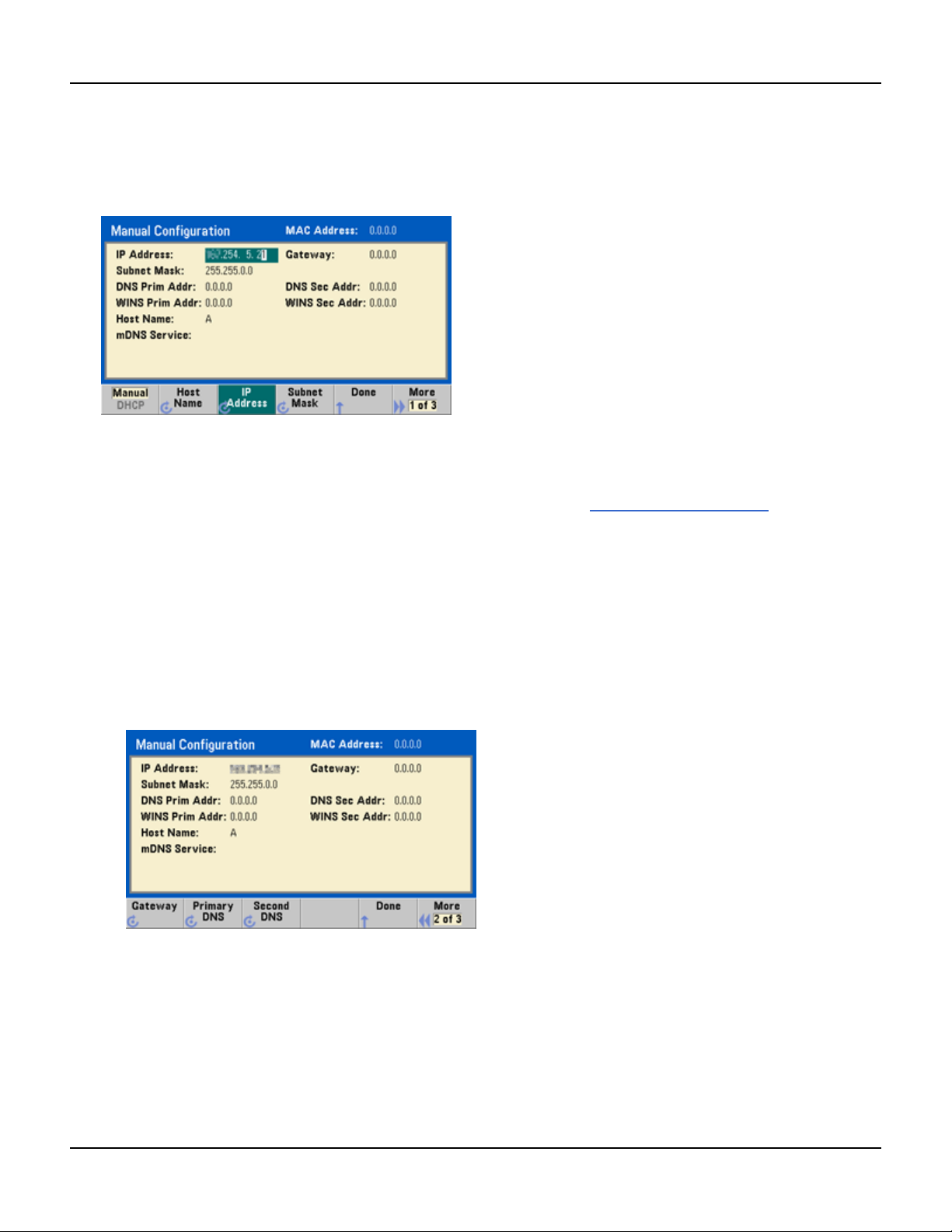
4. Establish an "IP Setup."
If you are not using DHCP (if the first softkey is set to Manual), you must establish an IP setup, including an IP
address, and possibly a subnet mask and gateway address. The IP Address and Subnet Mask buttons are on the
main screen, and you press More to configure the Gateway.
Contact your network administrator for the IP address, subnet mask, and gateway to use. All IP addresses take the
dot-notation form "nnn.nnn.nnn.nnn" where "nnn" in each case is a byte value in the range 0 through 255. You
can enter a new IP address using the numeric keypad (not the knob). Just type in the numbers and the period
delimiters using the keypad. Use the left cursor key as a backspace key. Do not enter leading zeros.
5. Configure the "DNSSetup" (optional)
DNS (Domain Name Service) is an Internet service that translates domain names into IP addresses. Ask your
network administrator whether DNS is in use, and if it is, for the host name, domain name, and DNS server
address to use.
a. Set the "hostname." Press Host Name and enter the hostname. A hostname is the host portion of the
domain name, which is translated into an IP address. The hostname is entered as a string using the knob and
cursor keys to select and change characters. The hostname may include letters, numbers, and dashes ("-").
You can use the keypad for the numeric characters only.
b. Set the "DNS Server" addresses. From the LAN configuration screen, press More to go to the second of three
sets of softkeys.
Enter the Primary DNS and Second DNS. See your network administrator for details.
More about IP Addresses and Dot Notation
Dot-notation addresses ("nnn.nnn.nnn.nnn" where "nnn" is a byte value from 0 to 255) must be expressed with care,
as most PC web software interprets byte values with leading zeros as octal (base 8) numbers. For example,
"192.168.020.011" is actually equivalent to decimal "192.168.16.9" because ".020" is interpreted as "16" expressed
in octal, and ".011" as "9". To avoid confusion, use only decimal values from 0 to 255, with no leading zeros.
56 Agilent Trueform Series Operating and Service Guide
Page 59

Set Up an Arbitrary Waveform
Set Up an Arbitrary Waveform
The instrument includes an embedded waveform editor that allows you to create and edit arbitrary waveforms. You can
create these waveforms by editing voltage values directly or by using an combination of up to 12 different kinds of
standard waveforms.
The following tutorial creates and edits a basic waveform.
Insert Built-in Waveforms
1. Start the embedded waveform editor by pressing [Waveforms] > Arb > Arbs. Press Edit New, accept the
default file name, and then Start Editor. You now have a 0 VDC waveform of exactly 8 points (33500 Series) or
32 points (33600 Series).
The rest of this tutorial is based on the embedded waveform editor in a 33500 Series instrument,
which has a minimum waveform size of 8 points. If you are using this tutorial on a 33600 Series
instrument, please note that the minimum waveform size for the embedded waveform editor is
32 points.
2. Press Insert Built-in > Choose Wave. Use the knob or the arrows below the knob to select D-Lorentz and
press OK. Use the keypad and the V softkey that appears when you start typing on the keypad to set the
Amplitude to 2 V, and then press OK. The waveform now has 100 additional points, as the D-Lorentz waveform
of 100 points was inserted in front of the initial waveform.
Agilent Trueform Series Operating and Service Guide 57
Page 60

Set Up an Arbitrary Waveform
3. Suppose that you want to undo the change that you just made. Press [System] > Undo. You are now back to
the original 0 V waveform.
4. To put the D-Lorentz waveform back, press Redo. Then press Done to exit.
5. Now we will insert a sine wave. Begin by pressing Choose Wave. Make sure Sine (the default) is highlighted, and
press OK. For help in understanding the various parameters on the screen, press Parameter Help. Then press
Done to exit the help screen.
58 Agilent Trueform Series Operating and Service Guide
Page 61

Set Up an Arbitrary Waveform
6. Using the numeric keypad and the up and down arrow softkeys, set the Amplitude to 3.5 V, the Cycles to 4, and
the Points to 200. Leave all other settings at their default values and press OK.
7. Notice that the first softkey, Select Point # is highlighted. Put the marker on the 270th waveform point by using
the numeric keypad to enter the number 270 and pressing Enter.
8. Press Choose Wave, select Square, and then press OK. Set the Amplitude to 3 V, the Offset to -2 V, the Cycles
to 8, and the Points to 100. Press OK. Notice that the 8 square wave cycles have been inserted, beginning at the
marker. Press Done.
Agilent Trueform Series Operating and Service Guide 59
Page 62
Set Up an Arbitrary Waveform
Edit Waveform Characteristics
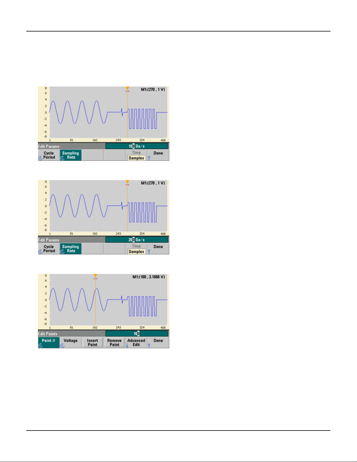
1. Press Edit Params and then set the Sampling Rate to 100 Sa/s. Press Cycle Period and notice that it has been
set to 4.08 seconds. This is because you have 408 sample points in the waveform, and the sample rate is 100
Sa/s.
2. Change the Cycle Period to 2.04 seconds and then press Sampling Rate. It will now be set to 200 Sa/s in order
to play the 408 point waveform in 2.04 seconds.
3. Press Done to exit the parameter editing screen. Press Edit Points and notice that the Point # softkey is
highlighted. Enter the number 160 and press Enter to move the marker.
60 Agilent Trueform Series Operating and Service Guide
Page 63

Set Up an Arbitrary Waveform
4. Press Voltage and change the voltage of the selected point to 4.2 V. Press Point # and change the point marker
to 150 to move the marker off the point. When you press Enter to finish entering point 150, you will see the 4.2 V
anomaly in the wave that you just created at point 160.
Agilent Trueform Series Operating and Service Guide 61
Page 64

Set Up an Arbitrary Waveform
Zoom and Pan
1. To see the point in detail, press [System] > Pan/Zoom Control. Notice that the first softkey is set to
Horizontal, meaning that the zooming that we are about to do will be along the horizontal (time) axis. Change
the Zoom to 500%, and the sine wave anomaly will be more obvious.
2. Now set the first softkey to Vertical to zoom vertically. Set the Zoom to 500%. Notice that we have zoomed in on
the voltage axis, but we are too low to see the 4.2 V anomaly in the sine wave.
3. Press Pan and set the Pan to 3 V in order to move higher on the waveform. The 4.2 V point is now clearly visible.
62 Agilent Trueform Series Operating and Service Guide
Page 65

Set Up an Arbitrary Waveform
4. To see the entire waveform again, press Show All. Then press Done and Done again to return to the Edit
Points screen.
Insert, Remove, Copy and Paste Points
1. Press Insert Point 15 times and watch the display carefully. You will see 15 new waveform points at the same
voltage level.
2. Change the Point # to 220 and press Remove Point 20 times, watching the display carefully as you do so in
order to see the points being removed from the waveform.
Agilent Trueform Series Operating and Service Guide 63
Page 66

Set Up an Arbitrary Waveform
3. You can also edit points by using a table of voltages. Press Advanced Edit > Edit Via Table. Set Point # to 200,
and then set the Voltage for point 200 to 3 V. Use the knob to move between rows and set the Voltage for points
205 and 210 to 3 V. Press Done.
4. Notice the three 3 V spikes that you just made in the waveform at points 200, 205, and 210.
5. Press Cut/Copy Paste, and set Marker 1 to 150. Then press the first softkey and change the Marker to Marker
2. Set Marker 2 to 300. The range defined by the markers is now highlighted in black.
6. Press Copy, then Paste, and then At Start. Notice that section you copied is now duplicated at the beginning of
the waveform.
64 Agilent Trueform Series Operating and Service Guide
Page 67

Set Up an Arbitrary Waveform
7. Now press Paste > At End. The same section of the waveform now also appears at the very end.
8. Now press Paste and change the Point # to 500. Then press OK, and the same portion of the waveform will be
pasted in at point 500. Press Done to leave the Cut/Copy Paste menu.
Agilent Trueform Series Operating and Service Guide 65
Page 68

Set Up an Arbitrary Waveform
Perform Math
The embedded waveform editor allows you to perform mathematical operations on the waveform. First you set
markers to define the range of the waveform that you want to modify. You can then add, subtract or multiply that
portion of the waveform by another waveform, or you can transform the waveform in ways that do not involve other
waveforms.
1. Press Perform Math. Set Marker 1 to 400 and Marker 2 to 500.
2. Press Add, then select Haversine and OK. Set the Amplitude to 3 V, the Offset to 0 V, and press OK. Notice that
the highlighted section now rises in the middle as a result of the Haversine addition.
3. Now press Multiply and select the Sine wave (press OK). Set the Cycles to 2 and press OK.
66 Agilent Trueform Series Operating and Service Guide
Page 69

4. Now set Marker 1 to 200 and Marker 2 to 600.
5. Press Advanced Math > Mirror > OK.
Set Up an Arbitrary Waveform
6. Continue learning about the interface by trying other Advanced Math features, such as Invert, Absolute,
Scale, and so on. Press Operation Help for more information.
Agilent Trueform Series Operating and Service Guide 67
Page 70

Features and Functions
Features and Functions
This section contains details on instrument features, including front panel and remote interface operation. You may
want to read Front Panel Menu Reference first. See SCPI Programming Reference for details on SCPI commands and
queries. This section covers:
Output Configuration
Pulse Waveforms
Amplitude Modulation (AM) and Frequency Modulation (FM)
Phase Modulation (PM)
Frequency-Shift Keying (FSK) Modulation
Pulse Width Modulation (PWM)
Sum Modulation
Frequency Sweep
Burst Mode
Triggering
Dual Channel Operations
IQ Player (Optional)
System-Related Operations
Remote Interface Configuration
External Timebase Reference
Embedded Waveform Editor
Throughout this document, "default" states and values are identified. These are the power-on default states provided
you have not enabled the power-down recall mode (see Instrument State Storage).
68 Agilent Trueform Series Operating and Service Guide
Page 71

Output Configuration
Output Configuration
This section describes output channel configuration. Many commands associated with output configuration start with
SOURce1: or SOURce2: to indicate a certain channel. If omitted, the default is channel 1. For example, VOLT 2.5 sets
the output on channel 1 to 2.5 V, and SOUR2:VOLT 2.5 does the same for channel 2.
The instrument's display includes a "tab" for each channel that summarizes various aspects of each channel's output
configuration:
On a two-channel instrument, the tab for channel 1 will be yellow, and the tab for channel 2 will be green.
Output Function
The instrument includes eight standard waveforms: sine, square, ramp, pulse, triangle, noise, PRBS (pseudo-random
binary sequence), and DC. There are also nine built-in arbitrary waveforms, and you can create custom waveforms
with the embedded waveform editor.
The table below shows which functions are allowed (•) with modulation, sweep, and burst. Selecting a function that is
not allowed with a modulation or mode disables the modulation or mode.
Carrier AM FM PM FSK BPSK PWM Sum Burst Sweep
Sine and Square • • • • • • • •
Pulse • • • • • • • • •
Triangle and Ramp • • • • • • • •
Gaussian Noise • • •
a
PRBS • • • • •
Arbitrary Waveform • • •
b
b
•
• • •
Sequence • •
(a) Gated burst only
(b) Applies to sample clock, not whole waveform
l Frequency Limitations: Changing functions may change the frequency to meet the new function's frequency
limits.
l Amplitude Limitations: When the output units are Vrms or dBm, changing functions may lower the amplitude to
the maximum for the new function due to variation in waveform shapes. For example, a 5 Vrms square wave (into
50 Ω) changed to a sine will decrease to 3.536 Vrms (sine’s upper limit).
l Amplitude and offset cannot combine to exceed the instrument’s capability. The one you set last may be changed
to stay within limits.
l You may protect a device under test (DUT) by specifying upper and lower output voltage limits.
Agilent Trueform Series Operating and Service Guide 69
Page 72

Output Configuration
l Front Panel:
To select another waveform:
l For example, to specify a DC signal:
To produce the DC output:
l SCPI: [SOURce[1|2]:]FUNCtion <function>
The APPLy command configures a waveform with one command.
70 Agilent Trueform Series Operating and Service Guide
Page 73

Output Configuration
Output Frequency
The output frequency range depends on the function, model, and output voltage, as shown here. The default
frequency is 1 kHz for all functions, and the minimum frequencies are shown in the table below.
Function Minimum Frequency
Sine 1 µHz
Square 1 µHz
Ramp/Tri. 1 µHz
Pulse 1 µHz
PRBS 1 µbps
Arbitrary 1 µSa/s
l Frequency Limitations: Changing functions may change the frequency to meet the new function's frequency
limits. Arbitrary waveforms retain their last frequency setting.
l Burst Limitation: For internally-triggered bursts, the minimum frequency is 126 µHz.
l Duty Cycle Limitations: For Square and Pulse, Duty Cycle on the 33500 Series is limited by the 16-ns minimum
pulse width specification. For example, at 1 kHz, Duty Cycle may be set as low as 0.01%, because that would
result in a pulse width of 100 ns. At 1 MHz, the minimum Duty Cycle is 1.6%, and at 10 MHz it is 16%. Changing
to a frequency that cannot produce the current duty cycle will adjust the duty cycle to meet the minimum pulse
width specification.
On the 33500 Series, the minimum pulse width is 16 ns. On the 33600 Series, the minimum pulse width is 5 ns
up to 4 Vpp and 8 ns up to 10 Vpp.
l Front Panel:
l SCPI: [SOURce[1|2]:]FREQuency {<frequency>|MINimum|MAXimum|DEFault}
The APPLy command configures a waveform with one command.
Agilent Trueform Series Operating and Service Guide 71
Page 74

Output Configuration
Output Amplitude
The default amplitude is 100 mVpp (into 50 Ω) for all functions.
l Offset Voltage Limitations: The relationship between amplitude and offset is shown below. Vmax is ±5 V for a 50 Ω
load or ±10 V for a high-impedance load.
Vpp < 2(Vmax – |Voffset|)
l Limits Due to Output Termination: If the amplitude is 10 Vpp and you change the output termination setting from
50 Ω to "high impedance" (OUTPut[1|2]:LOADINF), the displayed amplitude doubles to 20 Vpp. Changing from
"high impedance" to 50 Ω halves the displayed amplitude. The output termination setting does not affect the
actual output voltage; it only changes the values displayed and queried from the remote interface. Actual output
voltage depends on the connected load.
l Limits Due to Units Selection: Amplitude limits are sometimes determined by the output units selected. This may
occur when the units are Vrms or dBm due to the differences in various functions' crest factors.For example, if
you change a 5 Vrms square wave (into 50 Ω) to a sine wave, the instrument will adjust the amplitude to 3.536
Vrms (the upper limit for sine in Vrms). The remote interface will also generate a "Settings conflict" error.
l You can set the output amplitude in Vpp, Vrms, or dBm. You cannot specify output amplitude in dBm if output
termination is set to high impedance. See Output Units for details.
l Arbitrary Waveform Limitations: For arbitrary waveforms, amplitude is limited if the waveform data points do not
span the full range of the output DAC (Digital-to-Analog Converter). For example, the built-in "Sinc" waveform
does not use the full range of values, so its maximum amplitude is limited to 6.087 Vpp (into 50 Ω).
l Changing amplitude may briefly disrupt output at certain voltages due to output attenuator switching. The
amplitude is controlled, however, so the output voltage will never exceed the current setting while switching
ranges. To prevent this disruption, disable voltage autoranging using VOLTage:RANGe:AUTO OFF. The APPLy
command automatically enables autoranging.
l Setting the high and low levels also sets the waveform amplitude and offset. For example, if you set the high level
to +2 V and the low level to -3 V, the resulting amplitude is 5 Vpp, with a -500 mV offset.
l A DC signal's output level is controlled by the offset voltage (DC Offset Voltage). The DC level may be between ±5 V
into a 50 Ω load or ±10 V with a high-impedance load.
l Front Panel:
To use a high level and low level instead:
72 Agilent Trueform Series Operating and Service Guide
Page 75

l SCPI:
[SOURce[1|2]:]VOLTage {<amplitude>|MINimum|MAXimum|DEFault}
[SOURce[1|2]:]VOLTage:HIGH {<voltage>|MINimum|MAXimum|DEFault}
[SOURce[1|2]:]VOLTage:LOW {<voltage>|MINimum|MAXimum|DEFault}
The APPLy command configures a waveform with one command.
Output Configuration
Agilent Trueform Series Operating and Service Guide 73
Page 76

Output Configuration
DC Offset Voltage
The default offset is 0 V for all functions.
l Limits Due to Amplitude: The relationship between offset voltage and output amplitude is shown below. The peak
output voltage (DC plus AC) cannot exceed the instrument output rating (±5 V into 50 Ω load, or ±10 V into an
open circuit).
l The relationship between offset voltage and output amplitude is shown below. Vmax is the maximum peak voltage
for the selected output termination (5 V for a 50 Ω load or 10 V for a high-impedance load).
|Voffset| < Vmax - Vpp/2
If the specified offset voltage is not valid, the instrument will adjust it to the maximum DC voltage allowed with the
specified amplitude. From the remote interface, a "Data out of range" error will also be generated.
l Limits Due to Output Termination: The offset range depends on the output termination setting. For example, if
you set offset to 100 mVDC and then change output termination from 50 Ω to "high impedance," the offset
voltage displayed on the front panel doubles to 200 mVDC (no error is generated). If you change from "high
impedance" to 50 Ω, the displayed offset voltage will be halved. See OUTPut[1|2]:LOAD for details. Changing the
output termination setting does not change the voltage present at the output terminals of the instrument. This
only changes the displayed values on the front panel and the values queried from the remote interface. The
voltage present at the instrument's output depends on the load connected to the instrument. See OUTPut
[1|2]:LOAD for details.
l Arbitrary Waveform Limitations: For arbitrary waveforms, amplitude is limited if the waveform data points do not
span the full range of the output DAC (Digital-to-Analog Converter). For example, the built-in "Sinc" waveform
does not use the full range of values, so its maximum amplitude is limited to 6.087 Vpp (into 50 Ω).
l Setting the high and low levels also sets the waveform amplitude and offset. For example, if you set the high level
to +2 V and the low level to -3 V, the resulting amplitude is 5 Vpp, with a -500 mV offset.
l To output a DC voltage level, select the DC voltage function (FUNCtion DC) and then set the offset voltage
(VOLTage:OFFSet). Valid values are between ±5 VDC into 50 Ω or ±10 VDC into an open circuit. While the
instrument is in DC mode, setting amplitude has no effect.
l Front Panel:
l SCPI:
[SOURce[1|2]:]VOLTage:OFFSet {<offset>|MINimum|MAXimum|DEFault}
[SOURce[1|2]:]VOLTage:HIGH {<voltage>|MINimum|MAXimum|DEFault}
[SOURce[1|2]:]VOLTage:LOW {<voltage>|MINimum|MAXimum|DEFault}
The APPLy command configures a waveform with one command.
74 Agilent Trueform Series Operating and Service Guide
Page 77

Output Configuration
Output Units
Applies to output amplitude only.
l Output units: Vpp (default), Vrms, or dBm.
l Setting is volatile.
l Units selection applies to front panel and remote interface operations. For example, if you select "VRMS" remotely,
the units are displayed as "VRMS" on the front panel.
l Amplitude units cannot be dBm if output termination set to high impedance. Calculating dBm requires finite load
impedance. In this case, units are converted to Vpp.
l You can convert between units. For example, to convert 2 Vpp to Vrms equivalent:
The converted value is 707.1 mVrms for a sine wave.
l Front Panel:
l SCPI: [SOURce[1|2]:]VOLTage:UNIT {VPP|VRMS|DBM}
Agilent Trueform Series Operating and Service Guide 75
Page 78

Output Configuration
Output Termination
The instrument has a fixed series output impedance of 50 Ω to the front panel channel connectors. If the actual load
impedance differs from the value specified, the displayed amplitude and offset levels will be incorrect. The load
impedance setting is simply a convenience to ensure that the displayed voltage matches the expected load.
l Output termination: 1 Ω to 10 kΩ, or infinite. The default is 50 Ω. The tab at the top of each channel indicates the
value of this setting.
l If you specify a 50 Ω termination but actually terminate into an open circuit, the output will be twice the value
specified. For example, if you set the DC offset to 100 mVDC (and specify a 50 Ω load) but terminate into an open
circuit, the actual offset will be 200 mVDC.
l Changing output termination setting, adjusts displayed output amplitude and offset (no error is generated). If the
amplitude is 10 Vpp and you change the output termination setting from 50 Ω to "high impedance" (OUTPut
[1|2]:LOADINF), the displayed amplitude doubles to 20 Vpp. Changing from "high impedance" to 50 Ω halves the
displayed amplitude. The output termination setting does not affect the actual output voltage; it only changes the
values displayed and queried from the remote interface. Actual output voltage depends on the connected load.
The output load can affect signal quality for pulse or other functions with high-speed transitions.
High load resistance can produce reflections.
l Units are converted to Vpp if output termination is high impedance.
l You cannot change output termination with voltage limits enabled, because instrument cannot know which
termination setting the limits apply to. Instead, disable voltage limits, set the new termination value, adjust
voltage limits, and re-enable voltage limits.
l
Front Panel:
l SCPI: OUTPut[1|2]:LOAD {<ohms>|INFinity|MINimum|MAXimum|DEFault}
76 Agilent Trueform Series Operating and Service Guide
Page 79
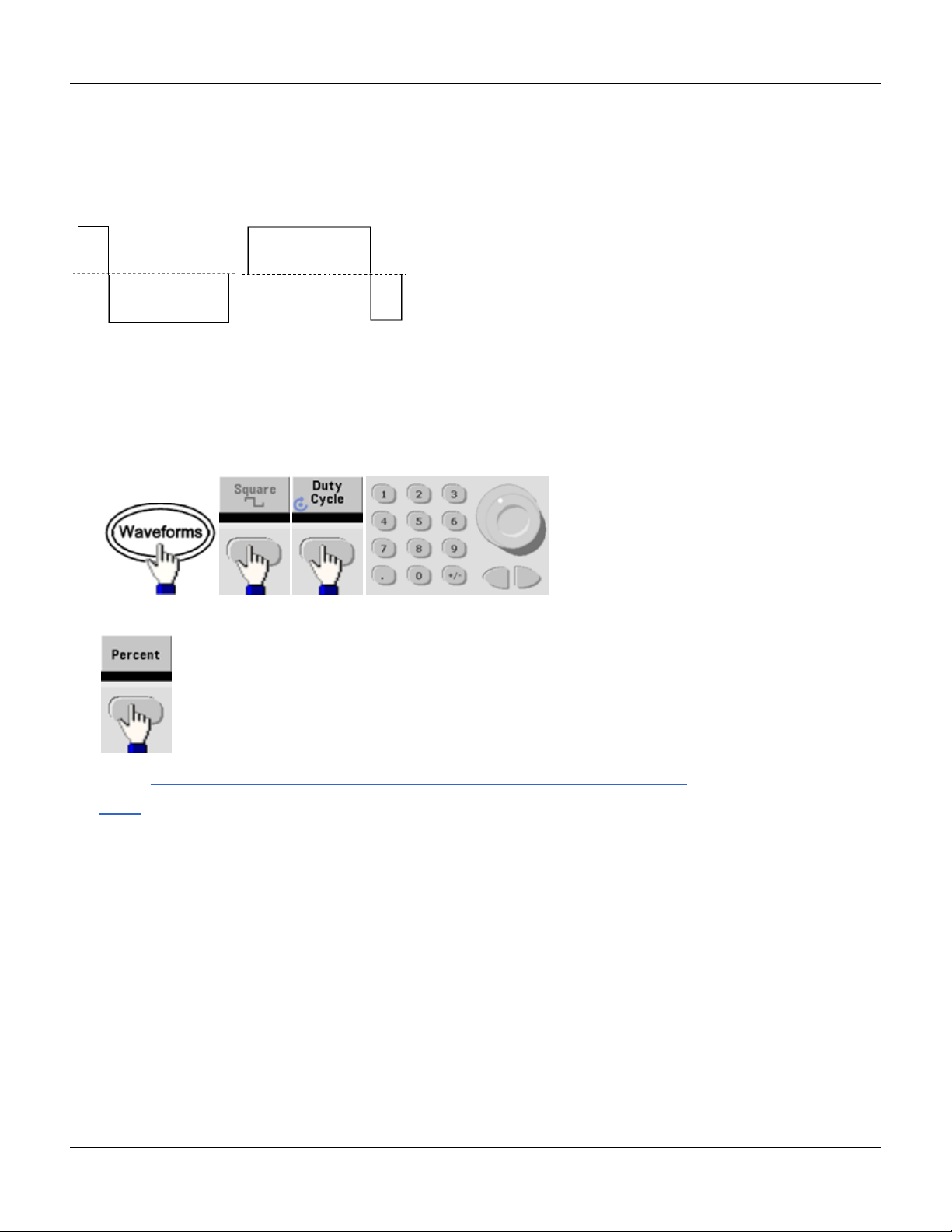
Output Configuration
Duty Cycle (Square Waves)
A square wave’s duty cycle is the fraction of time per cycle that the waveform is at a high level (assuming the waveform
is not inverted). (See Pulse Waveforms for pulse duty cycle details.)
20% Duty Cycle 80% Duty Cycle
l Duty Cycle:0.01% to 99.99% at low frequencies; range reduced at higher frequency. Stored in volatile memory;
default 50%.
l This setting is remembered when you change to another function. A 50% duty cycle is always used for a
modulating square waveform; the duty cycle setting applies only to a square wave carrier.
l Front Panel:
If you use the keypad, press Percent to finish:
l SCPI: [SOURce[1|2]:]FUNCtion:SQUare:DCYCle {<percent>|MINimum|MAXimum}
The APPLy command sets the duty cycle to 50%.
Agilent Trueform Series Operating and Service Guide 77
Page 80

Output Configuration
Symmetry (Ramp Waves)
Applies to ramp waves only. Symmetry represents the fraction of each cycle that the ramp wave is rising (assuming
waveform is not inverted).
0% Symmetry 100% Symmetry
l The symmetry (default 100%) is stored in volatile memory; and is remembered when you change to and from
other waveforms.
l When ramp is the modulating waveform for AM, FM, PM, or PWM, the symmetry setting does not apply.
l Front Panel:
Then choose one of the following options. The Symmetry option allows you to use the knob or keypad to specify a
value.
If you use the keypad, press Percent to finish:
l SCPI: [SOURce[1|2]:]FUNCtion:RAMP:SYMMetry {<percent>|MINimum|MAXimum|DEFault}
The APPLy command sets the symmetry to 100%.
78 Agilent Trueform Series Operating and Service Guide
Page 81

Output Configuration
Voltage Autoranging
Autoranging is enabled by default and the instrument selects optimal attenuator settings. With autoranging disabled,
the instrument uses the current attenuator settings and does not switch attenuator relays.
l You can disable autoranging to eliminate momentary disruptions caused by attenuator switching while changing
amplitude. However:
l The amplitude and offset accuracy and resolution (and waveform fidelity) may be adversely affected when
reducing the amplitude below a range change that would occur with autoranging on.
l You may not achieve minimum amplitude with autoranging on.
l Some instrument specifications do not apply with autoranging off.
l Front Panel:
or
l SCPI: [SOURce[1|2]:]VOLTage:RANGe:AUTO {OFF|0|ON|1|ONCE}
The APPLy command always enables autoranging.
Output Control
By default, channel output is disabled at power on to protect other equipment. To enable a channel's output, see below.
When channel output is enabled, the corresponding channel button is lit.
l If an external circuit applies excessive voltage to a channel output connector, the instrument generates an error
message and disables the output. To re-enable output, remove the overload and turn the channel on again.
l Front Panel:
l SCPI: OUTPut[1|2] {ON|1|OFF|0}
The APPLy command always enables the channel output connector.
Agilent Trueform Series Operating and Service Guide 79
Page 82

Output Configuration
Waveform Polarity
In normal mode (default), the waveform goes positive at the beginning of the cycle. Inverted mode does the opposite.
l As shown below, the waveform is inverted relative to the offset voltage. The offset voltage remains unchanged
when the waveform is inverted.
No Offset Voltage With Offset Voltage
l The Sync signal associated with an inverted waveform is not inverted.
l Front Panel:
or
l SCPI: OUTPut[1|2]:POLarity {NORMal|INVerted}
80 Agilent Trueform Series Operating and Service Guide
Page 83

Output Configuration
Sync Output Signal
A sync output is provided on the front panel Sync connector. All of the standard output functions (except DC and
noise) have an associated Sync signal. For applications where you may not want to output the Sync signal, you can
disable the Sync connector. The Sync signal may be derived from either output channel in a two-channel instrument.
General Behavior
l By default, the Sync signal is derived from channel 1 and is routed to the Sync connector (enabled).
l When the Sync signal is disabled, the output level on the Sync connector is at a logic "low."
l The polarity of the Sync signal is specified by OUTPut:SYNC:POLarity {INVerted|NORMal}.
l Inverting a waveform (see Waveform Polarity), does not invert the associated Sync signal .
l For sine, pulse, ramp, square, and triangle waves, the Sync signal is a square wave that is "high" in the first half of
the cycle and "low" in the last half. The Sync signal’s voltages are TTL-compatible when its load impedance
exceeds 1 kΩ.
l For arbitrary waveforms, the Sync signal rises at the beginning of the waveform and falls at the middle of the
arbitrary waveform. You can override this default behavior by using MARKer:POINt to specify the point within the
arbitrary waveform at which the Sync signal transitions to "low."
Modulation
l For internally-modulated AM, FM, PM, and PWM, the Sync signal is normally referenced to the modulating
waveform (not the carrier) and is a square waveform with a 50% duty cycle. The Sync signal is a TTL "high"
during the first half of the modulating waveform. You can set up the Sync signal to follow the carrier waveform by
using the command OUTPut:SYNC:MODE {CARRier|NORMal|MARKer} when modulating with internal modulation.
l For externally-modulated AM, FM, PM, and PWM, the Sync signal is referenced to the carrier waveform (not the
modulating waveform) and is a square waveform with a 50% duty cycle.
l You can override normal sync behavior to force Sync to always follow the carrier waveform (OUTPut
[1|2]:SYNC:MODE CARRier).
l For FSK, the Sync signal is referenced to the FSK rate. The Sync signal is a TTL "high" on the transition to the
"hop" frequency.
Sweep
l The Sync signal is a TTL "high" at the beginning of the sweep and goes "low" at the sweep's midpoint. The Sync
signal is synchronized with the sweep, but is not equal to the sweep time because its timing includes the re-arm
time.
l For frequency sweeps with Marker On, the Sync signal is a TTL "high" at the beginning of the sweep and a "low" at
the marker frequency. You can change this with OUTPut[1|2]:SYNC:MODE MARKER.
Agilent Trueform Series Operating and Service Guide 81
Page 84

Output Configuration
Burst
l For a triggered burst, the Sync signal is a TTL "high" when the burst begins. The Sync signal is a TTL "low" at the
end of the specified number of cycles (may not be the zero-crossing point if the waveform has an associated start
phase). For an infinite count burst, the Sync signal is the same as for a continuous waveform.
l For an externally-gated burst, the Sync signal follows the external gate signal. However, the signal will not go
"low" until the end of the last cycle (may not be a zero-crossing if the waveform has an associated start phase).
Configuring Sync Output
l Front Panel:
To toggle Sync off and on:
To configure Sync:
l SCPI:
OUTPut:SYNC {ON|1|OFF|0}
OUTPut[1|2]:SYNC:MODE {NORMal|CARRier|MARKer}
OUTPut[1|2]:SYNC:POLarity {NORMal|INVerted}
OUTPut:SYNC:SOURce {CH1|CH2}
82 Agilent Trueform Series Operating and Service Guide
Page 85

Pulse Waveforms
Pulse Waveforms
As shown below, a pulse or square wave consists of a period, a pulse width, a rising edge, and a falling edge.
Period
l Period: reciprocal of maximum frequency to 1,000,000 s. The default is 1 ms.
l The instrument adjusts the pulse width and edge time as needed to accommodate the specified period.
l Front Panel:
Select Pulse waveform:
Select period instead of frequency:
Set the period:
l SCPI: [SOURce[1|2]:]FUNCtion:PULSe:PERiod {<seconds>|MINimum|MAXimum|DEFault}
Agilent Trueform Series Operating and Service Guide 83
Page 86

Pulse Waveforms
Pulse Width
Pulse width is the time from the 50% threshold of a pulse's rising edge to the 50% threshold of the next falling edge.
l Pulse width: up to 1,000,000 s (see restrictions below). The default pulse width is 100 μs. The minimum pulse
width is 16 ns on the 33500 Series and 5 ns up to 4 Vpp or 8 ns up to 10 Vpp on the 33600 Series.
l The specified pulse width must also be less than the difference between the period and the minimum pulse width.
l The instrument will adjust the pulse width to accommodate the specified period.
l Front Panel:
l SCPI: [SOURce[1|2]:]FUNCtion:PULSe:WIDTh {<seconds>|MINimum|MAXimum|DEFault}
84 Agilent Trueform Series Operating and Service Guide
Page 87

Pulse Waveforms
Pulse Duty Cycle
The pulse duty cycle is defined as follows:
Duty Cycle = 100(Pulse Width)/Period
Pulse width is the time from the 50% threshold of a pulse's rising edge to the 50% threshold of the next falling edge.
l Pulse duty cycle: 0.01% to 99.99% (see restrictions below). The default is 10%.
l The pulse duty cycle must conform to the following restrictions determined by the minimum pulse width (Wmin).
The instrument will adjust the pulse duty cycle to accommodate the specified period.
Duty Cycle > 100(Minimum Pulse Width) / Period
and
Duty Cycle < 100(1 – (Minimum Pulse Width/ Period))
The minimum pulse width is 16 ns on the 33500 Series and 5 ns up to 4 Vpp or 8 ns up to 10 Vpp on the 33600
Series.
l The longer the edges, the greater the minimum pulse width. Longer edges will therefore restrict duty cycle more
than shorter edges.
l Front Panel:
Select pulse function:
Toggle to Duty Cycle:
Enter the Duty Cycle:
l SCPI: [SOURce[1|2]:]FUNCtion:PULSe:DCYCle {<percent>|MINimum|MAXimum|DEFault}
Agilent Trueform Series Operating and Service Guide 85
Page 88
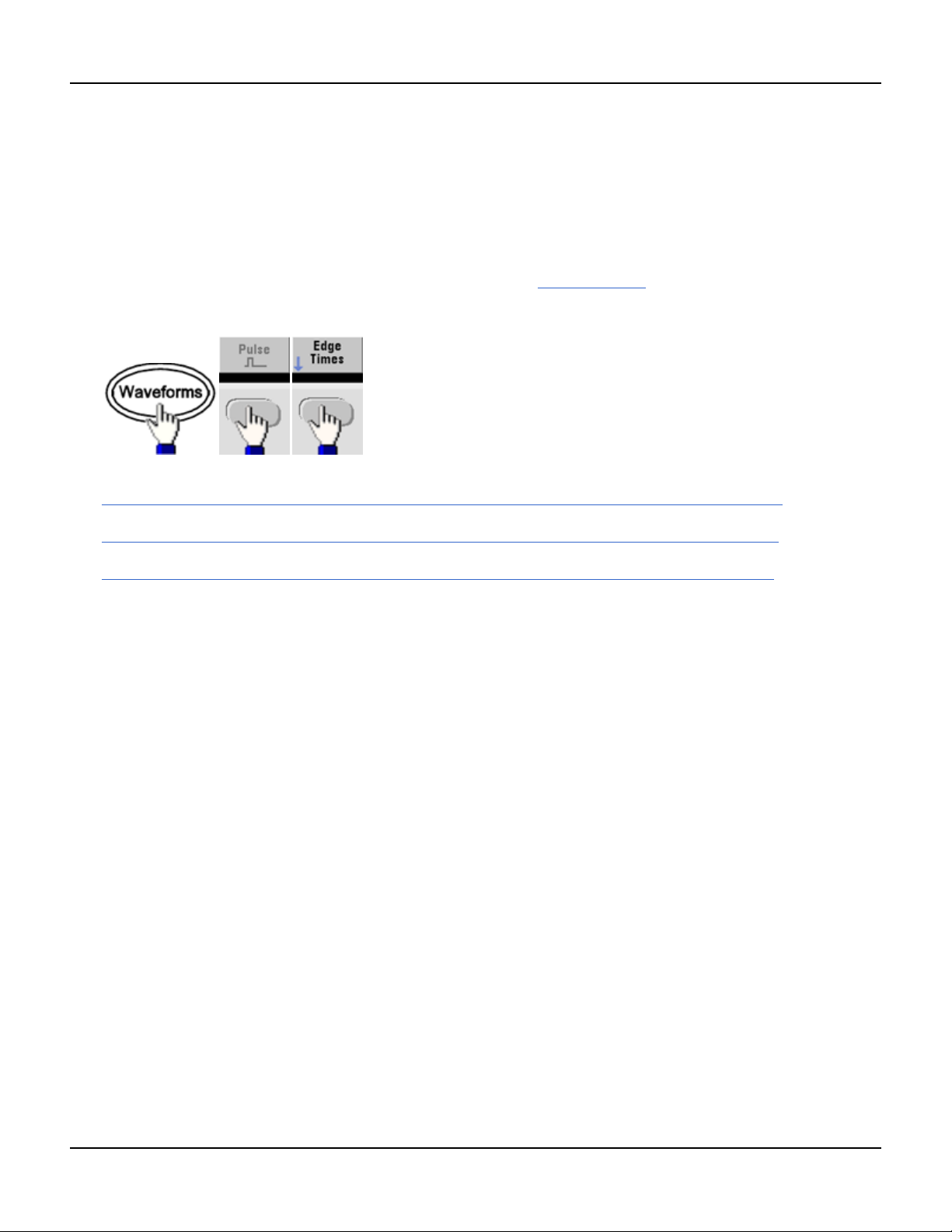
Pulse Waveforms
Edge Times
The edge times set the transition times for the leading and trailing edges of the pulse, either independently or together.
The edge time represents the time between the 10% and 90% thresholds.
l Edge time: Minimum of 8.4 ns on the 33500 Series, and 2.9 ns up to 4 Vpp, or 3.3 ns up to 10 Vpp on the 33600
Series. Maximum of 1 μs and default 10 ns.
l The specified edge time must fit within the specified pulse width as shown above. The instrument will adjust the
edge time to accommodate the specified pulse width.
l Front Panel:
l SCPI:
[SOURce[1|2]:]FUNCtion:PULSe:TRANsition:LEADing {<seconds>|MINimum|MAXimum|DEFault}
[SOURce[1|2]:]FUNCtion:PULSe:TRANsition:TRAiling {<seconds>|MINimum|MAXimum|DEFault}
[SOURce[1|2]:]FUNCtion:PULSe:TRANsition[:BOTH] {<seconds>|MINimum|MAXimum|DEFault}
86 Agilent Trueform Series Operating and Service Guide
Page 89

Amplitude Modulation (AM) and Frequency Modulation (FM)
Amplitude Modulation (AM) and Frequency Modulation (FM)
A modulated waveform consists of a carrier waveform and a modulating waveform. In AM, the carrier amplitude is
varied by the voltage level of the modulating waveform. In FM, the carrier frequency is varied by the voltage level of the
modulating waveform. The instrument accepts an internal or external modulation source. On a two-channel
instrument, one channel can modulate the other.
Select AM or FM before setting up any other modulation parameter. For more information on modulation, see
Modulation.
To Select AM or FM
l The instrument allows only one modulation mode to be enabled on a channel. When you enable AM or FM, all other
modulations are off. On two-channel models, the two channels’ modulations are independent from one another,
and the instrument can add modulated waveforms from two channels. See PHASe:SYNChronize and
COMBine:FEED for details.
l The instrument will not allow AM or FM to be enabled with sweep or burst. Enabling AM or FM, turns off sweep and
burst.
l To avoid multiple waveform changes, enable modulation after configuring the other modulation parameters.
l Front Panel:
or
Then turn modulation on:
The waveform is output using the present carrier and modulating waveform settings.
l SCPI:
[SOURce[1|2]:]AM:STATe{ON|1|OFF|0}
[SOURce[1|2]:]FM:STATe {ON|1|OFF|0}
Agilent Trueform Series Operating and Service Guide 87
Page 90

Amplitude Modulation (AM) and Frequency Modulation (FM)
Carrier Waveform Shape
l AM or FM carrier shape: Sine (default), Square, Ramp, Pulse, Triangle, Noise (AM only), PRBS, or Arbitrary
waveform. You cannot use DC as the carrier waveform.
l For FM, the carrier frequency must always be greater than or equal to the frequency deviation. Attempting to set a
deviation greater than the carrier frequency will cause the instrument to set the deviation equal to the carrier
frequency.
l The carrier frequency plus the deviation cannot exceed the selected function's maximum frequency plus 100 kHz.
If you attempt to set the deviation to an invalid value, the instrument adjusts it to the maximum value allowed
with the present carrier frequency. The remote interface also generates a "Data out of range" error.
l Front Panel:
Then select a waveform shape.
l SCPI:
[SOURce[1|2]:]FUNCtion <function>
The APPLy command configures a waveform with one command.
Carrier Frequency
The maximum carrier frequency varies by function, model, and output voltage, as shown here. The default is 1 kHz for
all functions other than arbitrary waveforms. Arbitrary waveform "frequency" is also set using the
FUNCtion:ARBitrary:SRATe command.
l Front Panel:
l SCPI: [SOURce[1|2]:]FREQuency {<frequency>|MINimum|MAXimum|DEFault}
The APPLy command configures a waveform with one command.
88 Agilent Trueform Series Operating and Service Guide
Page 91

Amplitude Modulation (AM) and Frequency Modulation (FM)
Modulating Waveform Shape
The instrument accepts an internal or external AM or FM modulation source. On a two-channel instrument you can
modulate one channel with the other.
You cannot modulate noise with noise, PRBS with PRBS, or an arbitrary waveform with an arbitrary
waveform.
l The modulating waveform shape (internal source) may be:
l Sine wave
l
Square with 50% duty cycle
l
UpRamp with 100% symmetry
l
Triangle with 50% symmetry
l
DnRamp with 0% symmetry
l Noise - white gaussian noise
l PRBS - Pseudo Random Bit Sequence (polynomial PN7)
l Arb - Arbitrary waveform
l Front Panel:
or
Then choose the modulating shape:
l SCPI:
[SOURce[1|2]:]AM:INTernal:FUNCtion <function>
[SOURce[1|2]:]FM:INTernal:FUNCtion <function>
Agilent Trueform Series Operating and Service Guide 89
Page 92

Amplitude Modulation (AM) and Frequency Modulation (FM)
Modulating Waveform Frequency
The instrument accepts an internal or external modulation source.
l Modulating frequency (internal source): minimum is 1 µHz, and the maximum values vary by model, function,
and output, as shown here.
l Modulating frequency (external source): 0 to 100 kHz
l Front Panel:
(33500 Series only)
or
Then enter the AM or FM frequency with the knob and keypad:
l SCPI:
[SOURce[1|2]:]AM:INTernal:FREQuency {<frequency>|MINimum|MAXimum|DEFault}
[SOURce[1|2]:]FM:INTernal:FREQuency {<frequency>|MINimum|MAXimum|DEFault}
90 Agilent Trueform Series Operating and Service Guide
Page 93

Amplitude Modulation (AM) and Frequency Modulation (FM)
Modulation Depth (AM)
The modulation depth is a percentage that represents the amplitude variation. At 0% depth, the amplitude is one-half
of the carrier’s amplitude setting. At 100% depth, the amplitude varies according to the modulating waveform, from
0% to 100% of the carrier’s amplitude.
l Modulation depth: 0% to 120%. The default is 100%.
l Even at greater than 100% depth, the instrument will not exceed ±5 V peak on the output (into a 50 Ω load). To
achieve modulation depth greater than 100%, output carrier amplitude may be reduced.
l Front Panel:
l SCPI: [SOURce[1|2]:]AM[:DEPTh] {<depth_in_percent>|MINimum|MAXimum}
Double Sideband Suppressed Carrier AM
The instrument supports two forms of amplitude modulation, "Normal" and Double Sideband Suppressed Carrier
(DSSC). In DSSC, the carrier is not present unless the modulating signal has an amplitude greater than zero.
l Front Panel:
l SCPI: [SOURce[1|2]:]AM:DSSC{ON|1|OFF|0}.
Agilent Trueform Series Operating and Service Guide 91
Page 94

Amplitude Modulation (AM) and Frequency Modulation (FM)
Frequency Deviation (FM)
The frequency deviation setting represents the peak variation in frequency of the modulated waveform from the carrier
frequency.
When the carrier is PRBS, frequency deviation causes a change in the bit rate equal to one-half of the set frequency.
For example, a 10 kHz deviation is equivalent to a 5 KBPS change in bit rate.
l Frequency deviation: 1 µHz to (carrier frequency)/2, default 100 Hz.
l For FM, the carrier frequency must always be greater than or equal to the frequency deviation. Attempting to set a
deviation greater than the carrier frequency will cause the instrument to set the deviation equal to the carrier
frequency.
l The carrier frequency plus the deviation cannot exceed the selected function's maximum frequency plus 100 kHz.
If you attempt to set the deviation to an invalid value, the instrument adjusts it to the maximum value allowed
with the present carrier frequency. The remote interface also generates a "Data out of range" error.
l Front Panel:
l SCPI: [SOURce[1|2]:]FM[:DEViation] {<peak_deviation_in_Hz>|MINimum|MAXimum|DEFault}
92 Agilent Trueform Series Operating and Service Guide
Page 95

Amplitude Modulation (AM) and Frequency Modulation (FM)
Modulating Source
The instrument accepts an internal or external modulation source. On a two-channel instrument you can modulate
one channel with the other.
On the 33600 Series, you can configure the modulation source to accept either a ±5 V signal or a ±1 V
signal. See INPut:ATTenuation[:STATe] for details.
l Modulating source: Internal (default), Other Channel, or External. The External modulation source may be up to
100 kHz.
l With the External source, an external waveform modulates the carrier waveform. The modulation depth (AM) or
frequency deviation (FM) is controlled by the signal level on the rear-panel Modulation In connector. The
external modulation input has -3 dB bandwidth of 100 kHz.
l AM example: with modulation depth 100%, when the modulating signal is at +5 V, the output will be at the
maximum amplitude. When the modulating signal at -5 V, the output will be at minimum amplitude.
l FM example: with deviation of 10 kHz, then a +5 V signal level corresponds to a 10 kHz increase in frequency.
Lower external signal levels produce less deviation and negative signal levels reduce the frequency below the
carrier frequency.
l Front Panel:
After enabling AM or FM, select the modulating source as shown:
l SCPI:
[SOURce[1|2]:]AM:SOURce {INTernal|EXTernal|CH1|CH2}
[SOURce[1|2]:]FM:SOURce {INTernal|EXTernal|CH1|CH2}
Agilent Trueform Series Operating and Service Guide 93
Page 96

Phase Modulation (PM)
Phase Modulation (PM)
A modulated waveform consists of a carrier waveform and a modulating waveform. PM is very similar to FM, but in PM
the phase of the modulated waveform is varied by the instantaneous voltage of the modulating waveform.
For more information on the fundamentals of Phase Modulation, see Tutorial - Modulation.
To Select Phase Modulation
l Only one modulation mode may be enabled at a time. Enabling PM disables the previous modulation mode.
l Enabling PM turns off sweep and burst.
l
Front Panel:
The waveform is output using the present carrier and modulating waveform settings.
l To avoid multiple waveform changes, enable modulation after configuring the other modulation parameters.
l SCPI: [SOURce[1|2]:]PM:STATe {ON|1|OFF|0}
Carrier Waveform Shape
l PM carrier shape: Sine (default), Square, Ramp, Triangle, Pulse, PRBS, or Arbitrary. You cannot use Noise or DC as
the carrier waveform.
l
Front Panel:
Then select any waveform except Noise or DC.
l SCPI: [SOURce[1|2]:]FUNCtion <function>
l The APPLy command configures a waveform with one command.
l When the carrier is an arbitrary waveform, modulation affects the sample "clock" instead of the full cycle defined
by the arbitrary waveform sample set. Because of this, applying phase modulation to arbitrary waveforms is
limited.
94 Agilent Trueform Series Operating and Service Guide
Page 97

Phase Modulation (PM)
Carrier Frequency
The maximum carrier frequency varies by function, model, and output voltage, as shown here. The default is 1 kHz for
all functions other than arbitrary waveforms. Carrier frequency must be greater than 20 times the peak modulation
frequency.
l Front Panel:
or or any other Frequency key.
After selecting the frequency key:
l SCPI: [SOURce[1|2]:]FREQuency {<frequency>|MINimum|MAXimum|DEFault}
l The APPLy command configures a waveform with one command.
Agilent Trueform Series Operating and Service Guide 95
Page 98

Phase Modulation (PM)
Modulating Waveform Shape
The instrument accepts an internal or external modulation source.
l The modulating waveform shape (internal source) may be:
l Sine wave
l
Square with 50% duty cycle
l
UpRamp with 100% symmetry
l
Triangle with 50% symmetry
l
DnRamp with 0% symmetry
l Noise - white gaussian noise
l PRBS - Pseudo Random Bit Sequence (polynomial PN7)
l Arbitrary waveform
l You can use noise as the modulating waveshape, but you cannot use noise or DC as the carrier waveform.
l Front Panel:
l SCPI: [SOURce[1|2]:]PM:INTernal:FUNCtion <function>
96 Agilent Trueform Series Operating and Service Guide
Page 99

Phase Modulation (PM)
Modulating Waveform Frequency
The instrument accepts an internal or external modulation source. The external modulation input has a -3dB
bandwidth of 100 kHz.
l Modulating frequency (internal): default 10 Hz, minimum 1 µHz; maximum varies by model, function, and output
voltage, as shown here.
l Front Panel:
Then set the modulating waveform frequency:
l SCPI: [SOURce[1|2]:]PM:INTernal:FREQuency {<frequency>|MINimum|MAXimum|DEFault}
Agilent Trueform Series Operating and Service Guide 97
Page 100
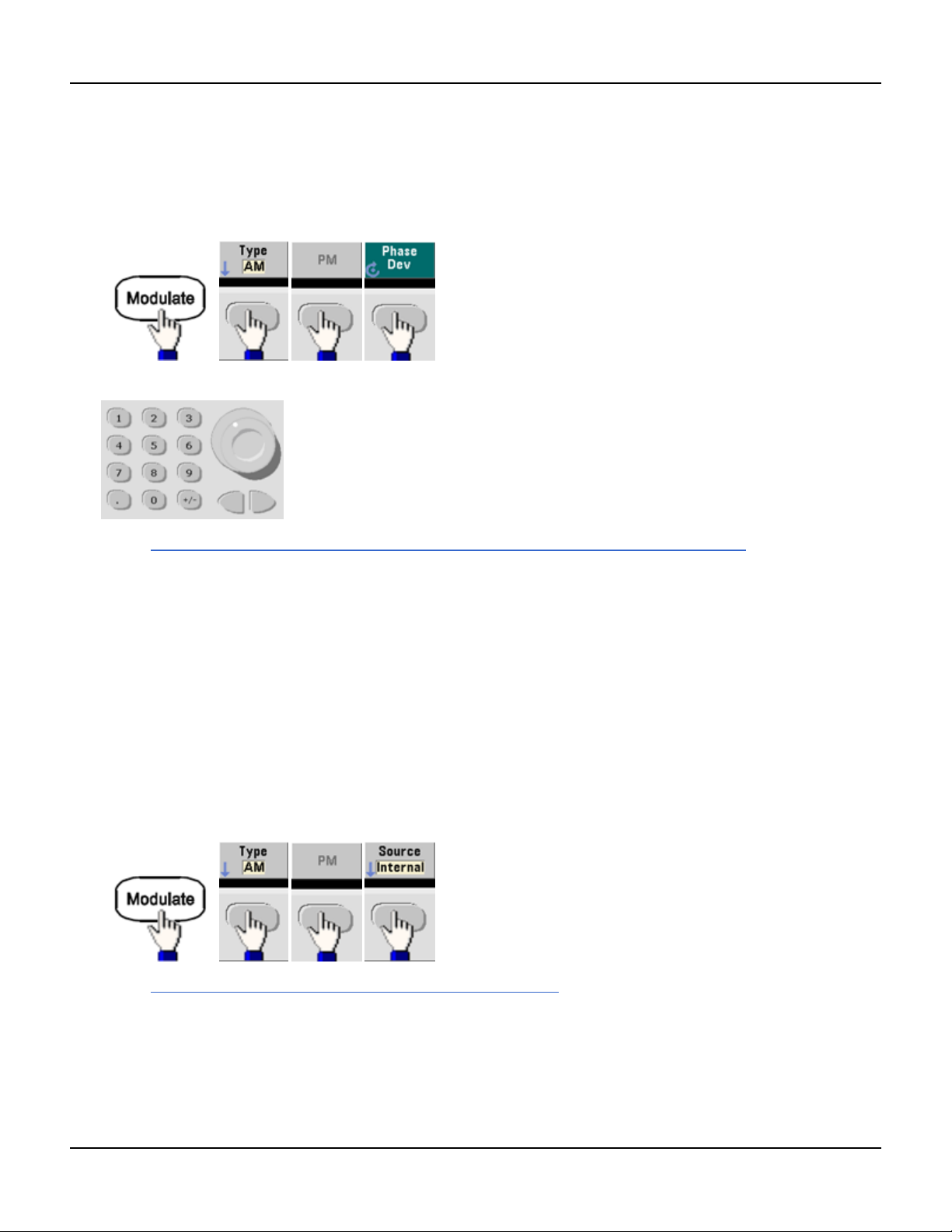
Phase Modulation (PM)
Phase Deviation
The phase deviation setting represents the peak variation in phase of the modulated waveform from the carrier
waveform. The phase deviation can be set from 0 to 360 degrees (default 180).
l Front Panel:
Then set the phase deviation:
l SCPI: [SOURce[1|2]:]PM:DEViation {<deviation in degrees>|MINimum|MAXimum|DEFault}
l When the carrier is an arbitrary waveform, the deviation applies to the sample clock. Therefore, the effect on the
full arbitrary waveform is much less than that seen with standard waveforms. The extent of the reduction depends
on the number of points in the arbitrary waveform.
Modulating Source
The instrument accepts an internal or external modulation source.
l Modulating source: Internal (default), Other Channel, or External. The External modulation source may be up to
100 kHz.
l With the External source, the carrier waveform is modulated with an external waveform. The ±5 V signal level
present on the rear-panel Modulation In connector controls the phase deviation. For example, if the deviation is
set to 180 degrees, a +5 V signal corresponds to a 180 degree phase shift. Lower levels produce less deviation.
l Front Panel:
l SCPI: [SOURce[1|2]:]PM:SOURce {INTernal|EXTernal|CH1|CH2}
98 Agilent Trueform Series Operating and Service Guide
 Loading...