

Page 1

Abstract
Pulsed battery drain currents, regulated charge currents, and remote
DUT (Device Under Test) fixtures,
dictate the need for specialized
power sourcing, loading, and measurement capabilities for testing
mobile communications devices.
Many of these capabilities are not
available in general-purpose system
power supplies.
This guide will assist the test system designer in selecting a system
power supply by properly evaluating test system and power supply
needs that are unique to the application and not immediately obvious. In this way, many problems
likely to arise in production can be
avoided.
Agilent AN 1310
Mobile Communications Device Testing
Application Note
Considerations when selecting a System Power Supply for Mobile
Communications Device Testing
Page 2

2
The growth of the mobile communications market is clearly in the newer
digital wireless products. The consumer advantages are significant—
improved transmission quality, accessibility, security, and operating time.
Digital mobile communications
devices transmit in short bursts
which conserves power between
transmissions, thus extending talk
time of the battery. Likewise, during
standby, some digital devices also
“wake up” and listen for incoming
calls in short bursts, again extending
battery life. The resulting battery
drain is pulsed current, ranging from
milliamperes to amperes. Accurate
current drain measurements are
important to assure proper battery
life for these different operating
modes.
Mobile communications devices incorporate a wide variety of battery
charging schemes. Constant and
pulsed charge currents ranging from
milliamperes to amperes are characteristic of rapid, slow, and trickle battery charge modes of these devices.
There are a variety of charge termination methods all primarily determined by battery voltage.
In the production testing of mobile
communications products, a system
power supply replaces the battery.
High volume manufacturing often dictates that the DUT fixture is remotely
located from the test system, introducing significant impedance due to
long wiring length. This, in combination with pulsed current drain, makes
it challenging to maintain a stable,
transient-free voltage at the fixture
just as if the DUT were operating
directly from a battery. In addition to
emulating the battery, the power supply can also provide current and voltage measurements required for testing and calibrating the DUT.
All of these things dictate the need
for a system power supply with power
sourcing, loading, and measurement
capabilities specially tailored for this
application. By properly evaluating
these unique needs of the test system
and power supply, the test system
designer can avoid production test
problems by selecting a power supply
suited for the application.
Considerations when Selecting a
System Power Supply
There are several unique needs to
consider in the system current supply
selection, specific to mobile communications device testing.
These needs can be categorized as
sourcing power, battery charger loading, and current measurement. This
guide is organized accordingly, as follows:
Section One
Considerations when Sourcing Power to
the DUT
A. Transient Voltage Drop at the DUT
Fixture
B. Pulsed Current Sourcing for DUT
Transmit Burst Current Drain
Section Two
Considerations when Loading the DUT
Battery Charger
A. Constant Voltage Loading
Capability
Section Three
Considerations when Making DUT Current
Measurements
A. Talk-mode Current Drain
Measurements
B. Standby-mode Current Drain
Measurements
C. Off-mode Current Leakage
Measurement
D. Battery Charger Current
Measurement
The following references are useful in
the selection of any system power
supply:
• Power Supply Testing, Application
Note 372-1, pub. # 5952-4190
• DC Power Supply Handbook,
Application Note 90B, pub. # 59524020
Overview
Mobile Communications System Power Supplies
Page 3

3
There are important factors the
designer needs to consider in sourcing power to the DUT:
A. Transient Voltage Drop at the DUT
Fixture
B. Pulsed Current Sourcing for DUT
Transmit Burst Current Drain
A stable DC voltage at the test fixture
is necessary in mobile communication device test. Transient voltage
drop can be a particular problem due
to the DUT transmit burst current
drain and the impedance of long
wiring connecting the test system to a
remote test fixture. If the transient
voltage drop is large enough, it will
activate the DUT low voltage shutdown circuit and disrupt the test,
impairing test throughput and yield.
Since digital mobile communications
products draw current in pulses, the
average current is low compared to
the pulsed current. Being able to
specify the power supply based on
pulsed instead of average current
capability can result in a smaller and
less costly unit.
Careful evaluation of these current
sourcing capabilities will assure optimum performance at the remote DUT
test fixture. More details on determining specific requirements on each
factor are provided in the following
sections.
A. Transient Voltage Drop at the
DUT Fixture
The combination of a device’s pulsed
current drain and the impedance of
wiring to the test fixture make it difficult to maintain a stable DC voltage
with low transient drop at the DUT. If
the resulting transient voltage drop is
large enough, it will activate the
DUT’s low voltage shutdown circuit,
disrupting the test. This impairs production throughput and yield. The
transient voltage drop should be kept
below 150 mV for mobile communications devices operating at 3.6 volts.
The transient voltage response specification on typical power supplies is
not adequate to assure proper performance in this application. It specifies the performance directly at the
power supply output terminals operating in local voltage sense mode. It
does not consider the wiring voltage
drop that the power supply is
attempting to compensate for when
operating in remote voltage sense
mode. Moreover, most power supplies
do not have sufficient speed to match
the fast rise and fall times of the DUT
transmit burst current. As a result,
the actual transient voltage drop may
be significant at the DUT even when
the power supply is operating in
remote voltage sense mode.
A suitably fast-responding power supply can provide an order of magnitude reduction of the transient voltage drop. However, at this fast
response speed, the test set wiring,
relays, connector resistance, wiring
inductance, and the DUT’s characteristics, all influence transient voltage
drop performance. A fast-responding
power supply typically provides optimum performance only over a specific
range of operating conditions.
Section One
Considerations when Sourcing Power to the DUT
Page 4
4
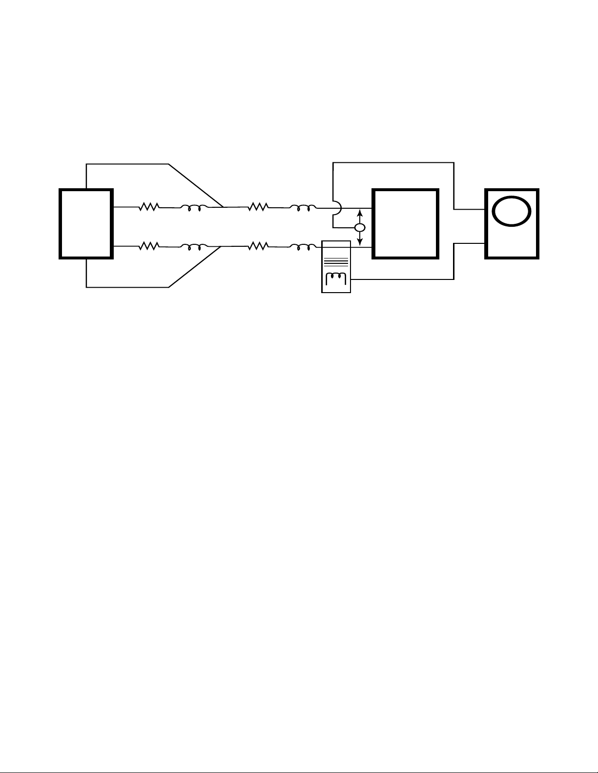
Test System Parasitic Elements
The parasitic elements in the test system are wiring, relay and connector
resistance, and wiring inductance,
modeled in Figure 1. To evaluate
transient voltage drop, one must test
over the range of expected parasitic
values. The variety of test platforms
in production, R&D, service, and
repair benches should also be considered in determining the range of parasitic values to be expected.
Typical parasitic values for the test
system wiring are as follows:
• Wiring inductance;
1.5 to 2 uH/meter untwisted,
0.5 to 1 uH/meter twisted
• Wiring resistance; depends on
diameter, add 50% for twisted
• Connector or relay resistance; initial: 0.01 to 0.05 ohms
• Connector or relay resistance; end
of life: 0.1 to 0.5 ohms
These values are for illustrative purposes. It is important to estimate the
parasitic values over the anticipated
test system life. Otherwise an increasing frequency of unexplainable intermittent problems could occur as the
test system connectors and relays
wear.
Always try to minimize these test system parasitic values as much as practical.
Simulating the Test System Parasitic
Elements
The best final proof of performance is
with the actual test system. When
using the test system, it is important
to ascertain the condition of the
relays and connectors. To properly
test at initial conditions, replace any
worn components.
In many cases the actual test system
may not exist yet. The test system
wiring parasitic values can be simulated using appropriate lengths and
diameters of actual wire pairs as
called for in the design. Untwisted
wire pairs should be kept closely
spaced to minimize loop area and
resulting inductance and noise pick
up. Connector and relay initial and
end of life resistance can be simulated using appropriate non-inductive
resistors.
It may be useful to set up a matrix for
the range of parameters and conditions to conduct the evaluation, similar to Table 1.
Figure 1: Test System Configuration Modeling
+Sense
+V
0
Power
Supply
R wire
+relays
+connectors
-V
0
L wire L wire V
-Sense
R
Sense
Point
wire
+connectors
Current
Probe
+
I
DUT
DUT
DUT
-
Oscilloscope
Page 5

5
The DUT Characteristics
The range of various different models
of DUT’s likely to be tested need to be
taken into consideration in the transient voltage drop evaluation testing.
Typical ranges of DUT talk-mode
operating values may be as follows.
• Operating voltage: 2.5 to 8.0 volts
• Talk-mode low level pulsed current
drain: 75 to 300 milliamperes
• Talk-mode high level pulsed current drain: 0.8 to 2 amperes
• Talk-mode initial peak transient
current drain: 1.2 to 3 amperes
• Pulsed current drain rise and fall
times:
TDMA: 25 microseconds or slower
GSM: 17 microseconds or slower
CDMA: 3 microseconds or slower
A mobile communications device’s
battery input port is very complex
with regard to its impedance and
actual pulse wave shape. It is important to conduct testing with actual
DUTs to verify true transient voltage
drop performance.
DUT Operating Conditions to Consider
The DUT should be set to maximum
transmit power and be operated at
the lowest input voltage to get maximum current drain. This will usually
give the largest transient voltage
drop. System performance should
also be verified at maximum DUT
operating voltage to verify that the
power supply still has adequate voltage reserve to compensate for peak
voltage drop in the wiring. Check
transient voltage drop performance
with all DUTs to be tested on the system. It is worthwhile documenting
the actual DUT characteristics used
to conduct the evaluation for future
reference.
Using an Electronic Load to Simulate the
DUT
One should not depend on using a
commercial electronic load or power
transistor and pulse generator to simulate the DUT pulsed drain current to
verify transient voltage drop performance. Their characteristics are very
different in comparison to an actual
DUT. The results will be approximate
at best, so the final proof is to always
use an actual DUT.
Table 1: Test System Parasitic Elements Matrix
Test system Wiring before voltage sense point Wiring after voltage sense point
Length L wire R initial R final Length L wire R initial R final
Auto test 6 m 4 uH 0.5 ohm 3 ohm 0.5 m 0.7 uH 0.2 ohm 0.4 ohm
set 1
Auto test 4 m 6 uH 0.7 ohm 1.4 ohm 0.2 m 0.3 uH 0.1 ohm 0.3 ohm
set 2
Bench test 1 m 2 uH 0.1 ohm 0.1 ohm 0.2 m 0.3 uH 0.1 ohm 0.1 ohm
set 1
Page 6
6
It may be useful to set up a matrix for
the range of parameters and conditions to track the results of the evaluation, as illustrated in Table 2. Again,
it is important to test the DUT at both
low and high operating voltage limits.
For More Information
Additional useful information on
reducing output voltage transient
drop at the DUT fixture can be found
in the following:
Minimizing Power Supply Transient
Voltage at a Digital Wireless
Telecommunications Products Test
Fixture, Technical Paper (located at
the Agilent Technologies Web site in
applications/technologies section,
www.agilent.com/find/power)
Table 2: Transient Voltage Drop Evaluation Results Matrix
DUT1 DUT2 DUT3
V drop/R initial V drop/R final V drop/R initial V drop/R final V drop/R initial V drop/R final
Auto test 100 mV 135 mV 110 mV 145 mV 90 mV 125 mV
set 1
Auto test 80 mV 105 mV 90 mV 115 mV 70 mV 95 mV
set 2
Bench test 70 mV 70 mV 80 mV 80 mV 60 mV 60 mV
set 1
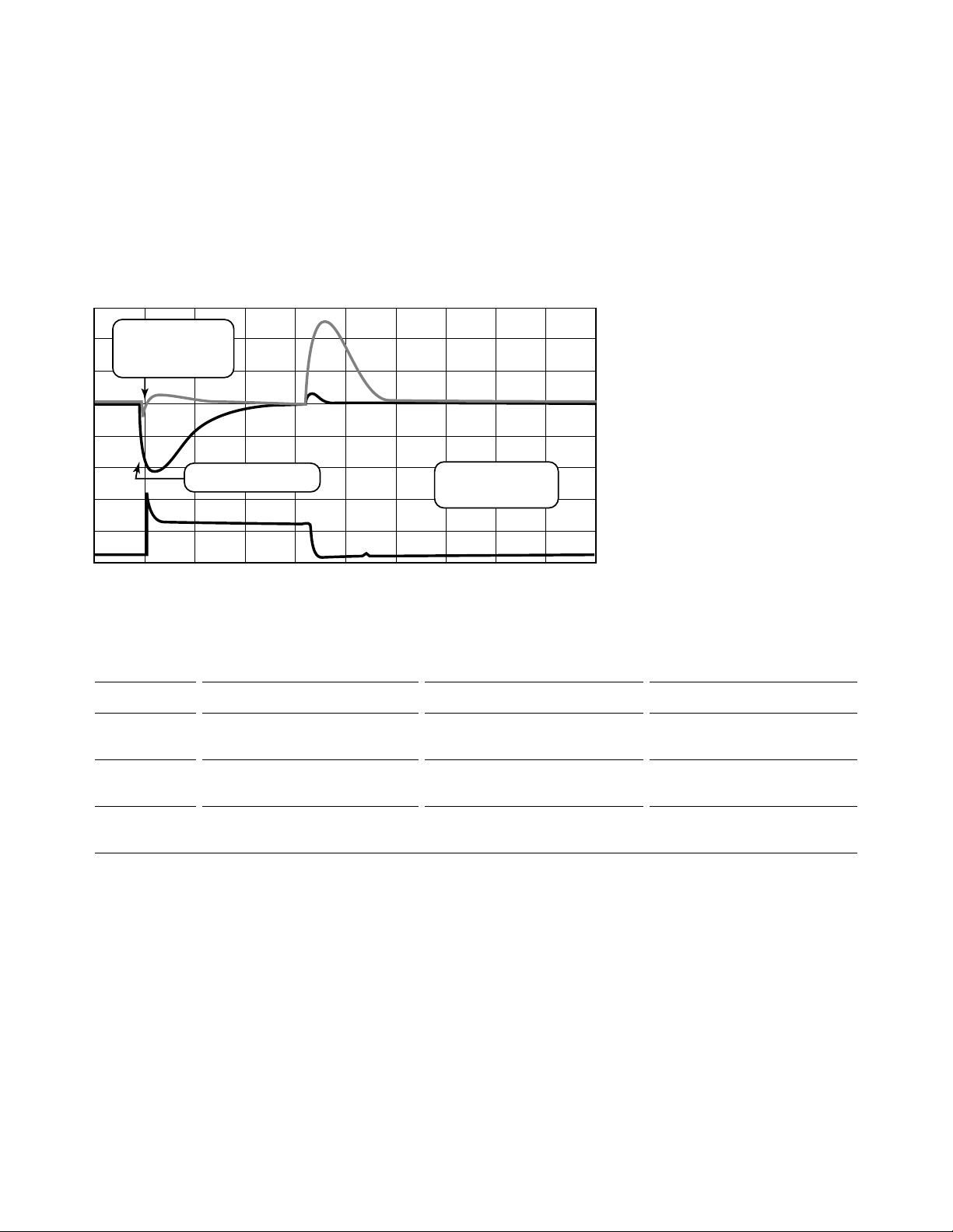
Figure 2: Transient Voltage Drop Measurement Results
The transient voltage drop performance and pulsed current drain are
measured directly at the DUT with
an oscilloscope and current probe, as
shown in Figure 1. Typical values of
these measurements are illustrated
in Figure 2.
Transient Voltage Drop Evaluation
Test Result Example
Fast Responding
dc Source
Standard dc Source
Ch 2: 200 mV/div
Ch 1: 500 mA/div
-680.00 us 120.00 us
1.12000 ms
Time
Page 7
7
B. Pulsed Current Sourcing for
DUT Transmit Burst Current Drain
Power supplies specifically developed
for this application may offer pulsed
current sourcing capability that
exceed their DC average current
sourcing capability. This effectively
provides more power in a smaller
package for digital mobile communications devices, which draw current
in pulses.
The Pulsed Current Drain of Digital Mobile
Communications Devices
Two common examples for transmit
bursts are TDMA and GSM products.
• TDMA transmits in 6.67 millisecond bursts with a
2
/6-duty cycle
• GSM transmits in 0.57 millisecond
bursts on a
1
/8-duty cycle
In application, the DUT operates at a
specified voltage and draws current
based on its power needs. The voltage
is being controlled by the power supply while the levels of current are
being determined by the DUT.
Simulating the DUT Pulsed Current Drain
The evaluation needs to reflect the
application conditions, to correctly
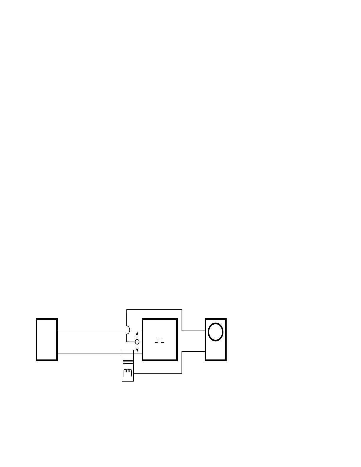
test the suitability of a power supply’s pulsed current sourcing capability. In Figure 3, the power supply is
set to the DUT operating voltage. An
electronic load is set to alternate
between two constant current levels
to simulate the pulsed current drain
of a DUT.
Both the DC average current and
pulsed current levels need to be considered. A power supply that provides
pulsed current sourcing capability
has a fast current limit to protect
from excess peak current drain and a
slow current limit to protect from
excess DC average current drain.
These limits protect the power supply
as well as the DUT.
Measuring the Power Supply’s Pulsed
Current Sourcing Capability
To measure the pulsed current sourcing capability, the electronic load
pulse duration is increased while
duty cycle is decreased to avoid
exceeding the DC average current
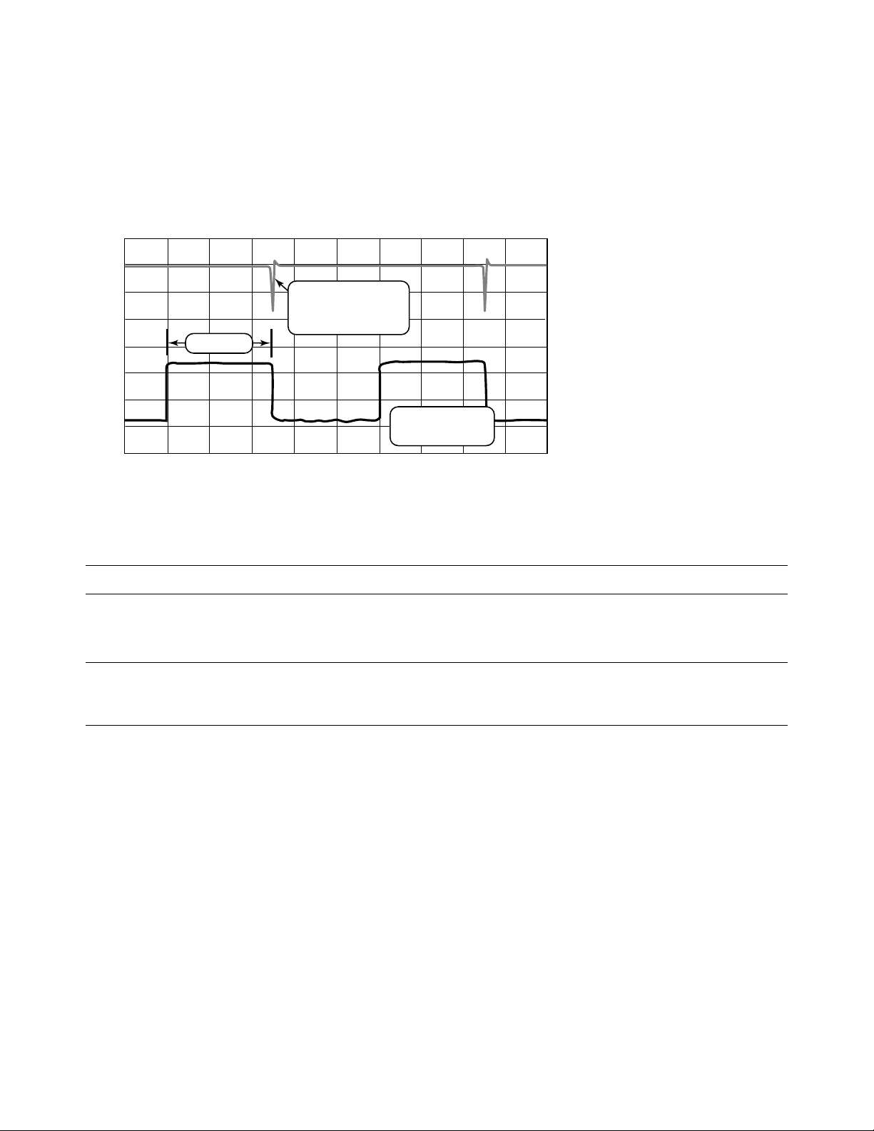
sourcing capability of the power supply. When the pulsed current sourcing capability is exceeded, the pulsed
current limit takes over control of the
source output collapsing the output
voltage. The pulse current source
duration is the time taken from the
start of the current pulse to the collapse of the output voltage as
observed by the oscilloscope trace
example in Figure 4. This testing can
be conducted at several pulse current
levels to determine the duration for
each as the duration may be a function of the pulse level.
Figure 3: Pulsed Current Source Capability Test Set Up
+V
0
+
Power
Supply
0
Current
Probe
--V
Pulsed
Load
V
LEAD
I
LEAD
Oscilloscope
Page 8
8
Applying a Short Circuit to Measure the
Pulsed Current Sourcing Capability
Applying a short circuit to the power
supply output may not correctly
measure the pulsed current source
duration as required in the application. A short circuit instantly drives
the power supply into current limit
operation. This does not reflect the
constant voltage operation and DUT’s
repetitive current pulse drain of the
application.
Minimizing the transient voltage drop
at the DUT fixture is a primary concern as it impacts production
throughput and yield. A fast responding power supply can significantly
reduce transient voltage drop. Output
pulsed current source capability is
beneficial by reducing the size and
cost of the power supply in the test
system.
The Agilent 66111A, 66311B/D and
66309B/D dc sources feature fast
response and pulsed current source
capability.
Figure 4: Pulsed Current Source Capability Measurement Results
Table 3: Power Sourcing Considerations Summary
Summary of considerations when sourcing current to the DUT
Power sourcing factor Considerations Evaluation method
Output transient voltage drop at DUT fixture Range of test systems and wiring parasitics Oscilloscope AC-mV measurement
(Low-transient battery voltage)
Range of DUT’s input characteristics Min. and max. wiring parasitics
Min. and max. DUT voltages
Output pulsed current source capability Range of DUT’s pulsed current Oscilloscope DC voltage and current time
(Transmit burst current drain) load levels and duration measurement
Adjustable pulsed load
Chan 2
Output voltage
dropping due to
current limit control
Duration
Chan 1
-10.000 ms 40.000 ms
Time
Ch 2: 200 mV/div
Ch 1: 500 mA/div
90.000 ms
realtime
Page 9

9
Mobile communications devices incorporate a wide variety of battery
charging schemes. In production test
the DUT charger is typically calibrated at high and low current levels for
accurate full and trickle charge rates.
There are a variety of charge termination methods, all primarily determined by battery voltage. The DUT’s
battery voltage sense needs to be calibrated to assure proper battery
charging termination. Improper
charger calibration can lead to
exploding batteries when the device
is in use.
To calibrate and test a mobile communications device’s battery charging
system, the current needs to be
drawn in reverse, out of the device’s
battery port. The need for a separate
load can be eliminated if the power
supply can provide this function.
To emulate a charging battery, the
system power supply needs to operate as a constant voltage electronic
load by maintaining a stable positive
voltage while sinking the charge current. The voltage needs to be regulated at the remote test fixture. The
power supply now needs to compen-
sate for the reverse voltage drop in
the wiring to the fixture. Considerations for constant voltage load operation are examined in detail in the following section.
A. Constant Voltage Loading
Capability
Mobile Communications Device Battery
Charger Operation
In battery charge mode, the mobile
communications device must regulate
the battery charge current and monitor the battery voltage to terminate
when the battery is fully charged.
Usually an external battery charger
connected to the charger-input port
on the device provides the power.
It is important that the DUT’s battery
charging current and voltage circuits
be tested and calibrated. Improper
calibration can result in under- or
over-charging, or worse, exploding
batteries, when the mobile communications device is in charge mode.
The Power Supply Emulating a Charging
Battery
In contrast to the more usual situation of sourcing current, the power
supply now needs to absorb, or sink
the battery charging current from the
DUT, while also maintaining an accurate, remotely sensed, positive voltage
at the DUT. The power supply is operating as a CV (Constant Voltage) electronic load.
Power Supply Considerations for CV Load
Operation
CV load operation is needed to calibrate the DUT’s internal battery voltmeter so that the DUT can accurately
sense the battery voltage low, high,
and charge termination points. The
CV load voltage should be within 0.5%
(20 mV for a 3.6 V battery) to calibrate the DUT charge circuit accurately. This allows margin for DUT
inaccuracies and still has the necessary accuracy for proper battery
charge-voltage termination.
The power supply’s current sinking
and power dissipating capabilities
and ability to maintain an accurate,
remotely-sensed, positive voltage at
the DUT are important features to
check in the evaluation. Many system
power supplies do not offer the capability of operating as a true CV load.
To evaluate CV load capability refer
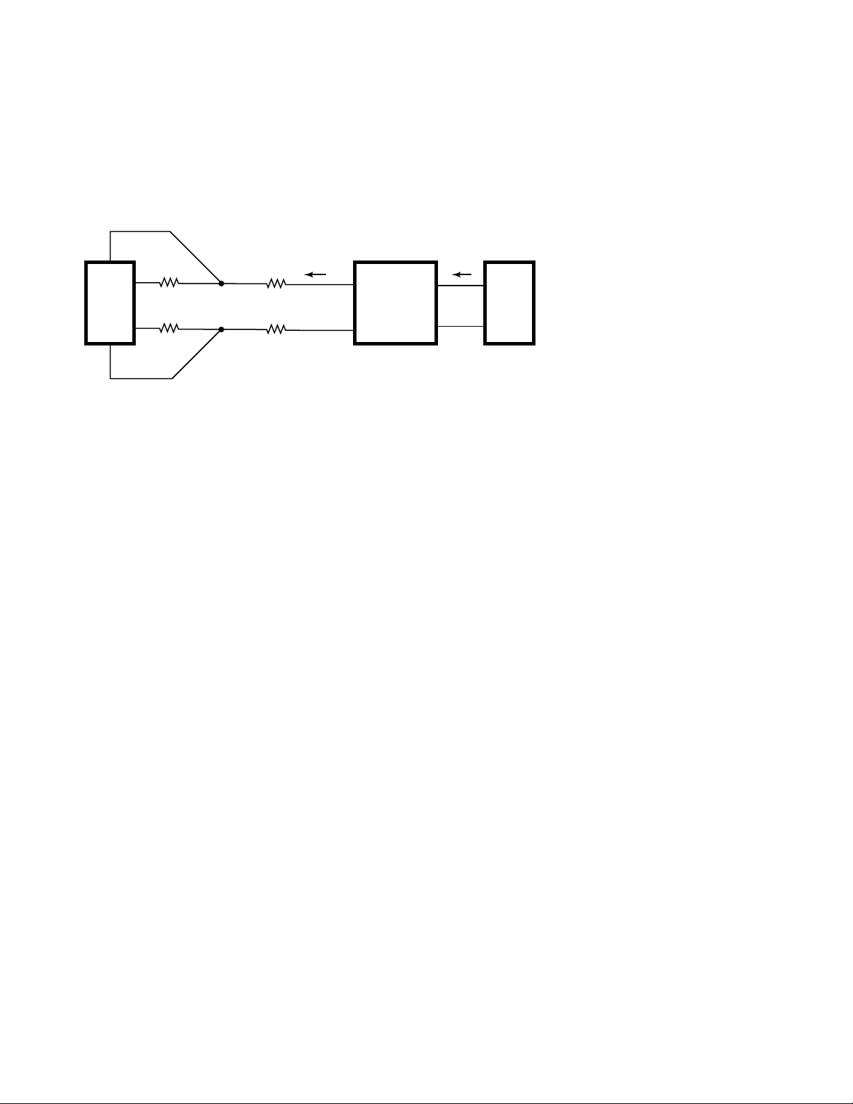
to Figure 5. With an appropriate
external battery-charging source connected to the DUT (an external battery charger or another DC source)
the DUT can be placed into battery
charge mode.
Because the main test system power
supply is now sinking current, its
remote sense must compensate for a
reverse wiring voltage drop. The voltage at the power supply output terminals will be less than the remote
sense voltage at the DUT fixture. As a
result, the power supply’s output will
be operating over a wide range of
voltage. At the upper extreme it may
be nearly 8 volts to emulate a fully
charged 7.2V battery pack under
trickle charge. At the lower extreme it
may need to operate near zero volts
to emulate a discharged 3.6V battery
back under rapid charge, while compensating for the wiring reverse voltage drop.
Section Two
Considerations when Loading the DUT Battery Charger
Page 10
10
Test System Fault-mode Consideration
during Battery Charger Calibration
For power supply remote sense opera-
tion, a separate pair of leads remotely
sense the voltage to accurately meas-
ure and regulate the voltage at the
DUT. Over time, the remote sense
connections can become intermittent
or open. Under these conditions most
system power supplies revert to local
sense operation, measuring and regu-
lating the voltage at the output termi-
nals. The power supply will appear to
continue to function properly as the
measured voltage will be the expected
value set. However, the voltage at the
remote DUT will be in error. This will
cause incorrect calibration, which can
result in under- or over-charging, or
worse, exploding batteries, when the
mobile communications device is in
use.
The test system designer should
assess the power supply’s behavior
for this fault mode and take neces-
sary precautions to prevent this from
occurring.
Summary of Important Items for Validating
Constant Voltage Load Capability
• Maximum current sinking capability
in CV load operation
• Maximum power dissipation capability at high voltage
• Over-power/temperature and
reverse current limit protection
• Output voltage-programming accuracy (< 0.5%)
• Maintains voltage regulation, especially at low voltage, end of relay
and connector life, and maximum
charge current, operating conditions
• Broken voltage sense lead faultmode behavior
Validating these capabilities by
reviewing specifications and making
some performance verifications
against specific application requirements, will assure proper CV load
performance for accurate and repeatable battery charger test and calibration.
The Agilent 66111A, 66311B/D,
and 66309B/D dc sources feature CV
load operation and uniquely provide
open sense lead fault detection. The
66309B/D dc sources have a second
output to provide power to the DUT
battery charger input port.
Figure 5: Test System Configuration during CV Load Operation
+Sense
I
battery
Battery
Port
+
-
Power
Supply/
Load
-Sense
+V
0
R wire
+relays
+connectors
-V
0
Sense
Point
R wire
+connectors
DUT
I
charger
+
Charger
Port
-
Charger
Power
Source
Page 11

11
The current measurement considerations when selecting a system power
supply for mobile communications
device testing are:
A. Talk-mode Current Drain
Measurements
B. Standby-mode Current Drain
Measurements
C. Off-mode Current Leakage
Measurement
D. Battery Charger Current
Measurement
Digital mobile communications
devices transmit in short bursts
which conserves power between
transmissions thus extending talk
time of the battery. Likewise, some
digital devices also “wake up” and listen for incoming calls in short bursts,
again extending battery life. The
resulting battery drain is continuous
or pulsed current, ranging from milliamperes to amperes.
Longer talk and standby operating
times are of primary importance to
the user. Accurate current drain
measurements are fundamental to
assure proper battery life and operating time. The wide range and pulsed
current drain characteristics can be
challenging to measure accurately.
If off-mode leakage current is high, it
can quickly drain the battery leading
to user dissatisfaction. Microampere
level measurement is needed to test
leakage current.
The DUT battery charger is typically
calibrated at high and low current
levels for accurate full and trickle
charge rates. Milliampere to amperelevel, negative current measurements
are needed to calibrate the device’s
battery charge circuit.
A DMM is often added, along with a
general-purpose power supply, to supplement the test system’s current
measurement capabilities. This does
not adequately address all these specialized requirements. Ideally, the
system power supply alone would
adequately address DUT battery current and voltage measurement
requirements, eliminating the need
for additional equipment. For this,
the power supply must have several
advanced measurement capabilities,
specifically developed for the application. Considerations for these measurement capabilities are explored in
detail in the following sections.
A. Talk-mode Current Drain
Measurements
Talk-mode current drain is the most
fundamental current measurement, to
assure the mobile communications
device will provide adequate battery
talk time. The pulsed current drain
characteristic of digital devices can
be challenging to measure accurately.
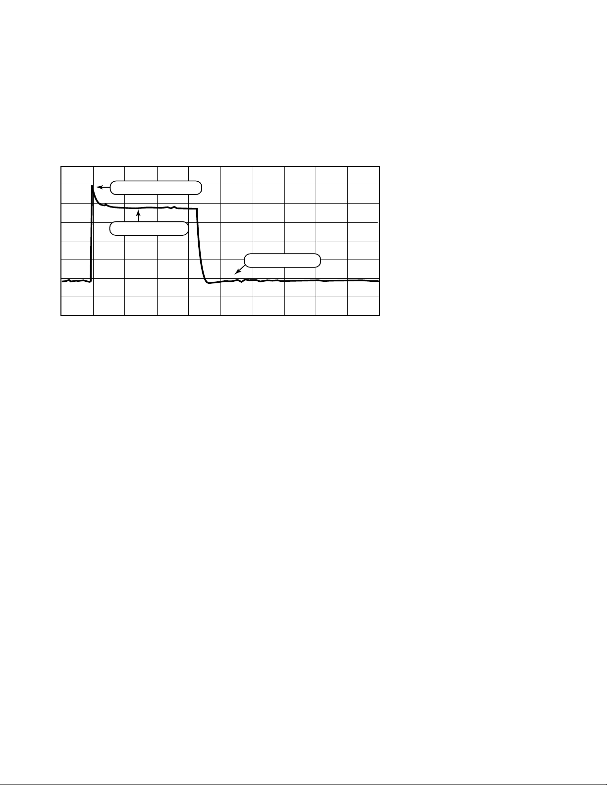
Pulsed Current Drain Characteristics
The pulsed current drain characteristics are typically within the following
ranges:
• Pulse periods from 5 to 100 milliseconds
• Crest factors exceeding ten
• Duty cycles from 10% to 50%
• The pulse may have a high peak
transient value to consider.
Section Three
Considerations when Making DUT Power Measurements
Page 12
12
DC Average Current Measurement
Considerations
Many times the DC average current
drain measurement is in error, or
erratic, because the pulse characteristics are not taken into consideration:
• The high crest factor may exceed
the instrument’s capability.
Usually the measurement is erroneously low, allowing defective
product to be passed.
• The high pulse level but low average value dictates milliampere
measurement accuracy over a full
2 to 3 ampere range.
• The relationship of pulse rate to
the test equipment’s measurement
window capability is overlooked.
This most often results in jittering
or erratic measurements.
For good accuracy and speed, a few
factors need to be considered when
selecting a product for making DC
average current measurements:
• The measurement system handles
high crest factors.
• The measurement window can be
set to measure exactly one or more
pulse periods when the pulse rate
is known precisely.
• The measurement system can
alternately provide accurate measurement when the pulse rate is not
known precisely.
• Measurement accuracy is 1-3 milliamperes over a full 2 to 3 ampere
range.
Most general-purpose power supplies
cannot provide adequate accuracy
due to the low DC average value relative to the large full-scale capability.
Second, the short and fixed measurement window they have is not well
suited for pulsed current drain measurements.
High Level and Peak Transient Current
Drain Measurements
Testing the pulsed current drain’s
high level and peak transient values
augments qualitative screening of the
DUT. Checking the high level ascertains transmitter power efficiency
and quality. Checking the peak overshoot current enhances talk time test
screening. A large peak current causes
a corresponding large momentary
battery voltage drop. Low battery
voltage shutdown occurs sooner,
reducing talk time.
It is unlikely to find these measurement
capabilities on any general-purpose
power supplies or most basic system
DMMs. If they are featured, it should
to be verified that the capabilities are
specifically suited for this application.
This is easily done using a wide band
AC/DC current probe and oscilloscope.
Figure 6: Typical Talk-mode Pulsed Current Drain Example.
Pulse peak transient
Pulse high level
Pulse low level
-200.00 us 800.00 us
Time
1.80000 ms
Page 13
13
B. Standby-mode Current
Drain Measurements
Long standby-mode operation is
extremely desirable, allowing the
mobile device to receive incoming
calls for many days before recharging
the battery. Accurate current measurements down to milliampere current levels are required to assure adequate standby-mode operating time.
Standby current may either be continuous or pulsed.
Continuous Standby Current Measurement
Continuous standby current drain is
typically tens of milliamperes, providing about two days-standby mode
operating time. The equipment should
be able to measure the standby current drain at a few percent or better
accuracy (<1 mA) to assure adequate
DUT standby time performance.
Most general-purpose power supplies
do not have adequate accuracy for
standby current drain measurement
due to its low value relative to the
large full-scale capability.
Slotted-mode Standby Operation and
Pulsed Current Drain Measurement
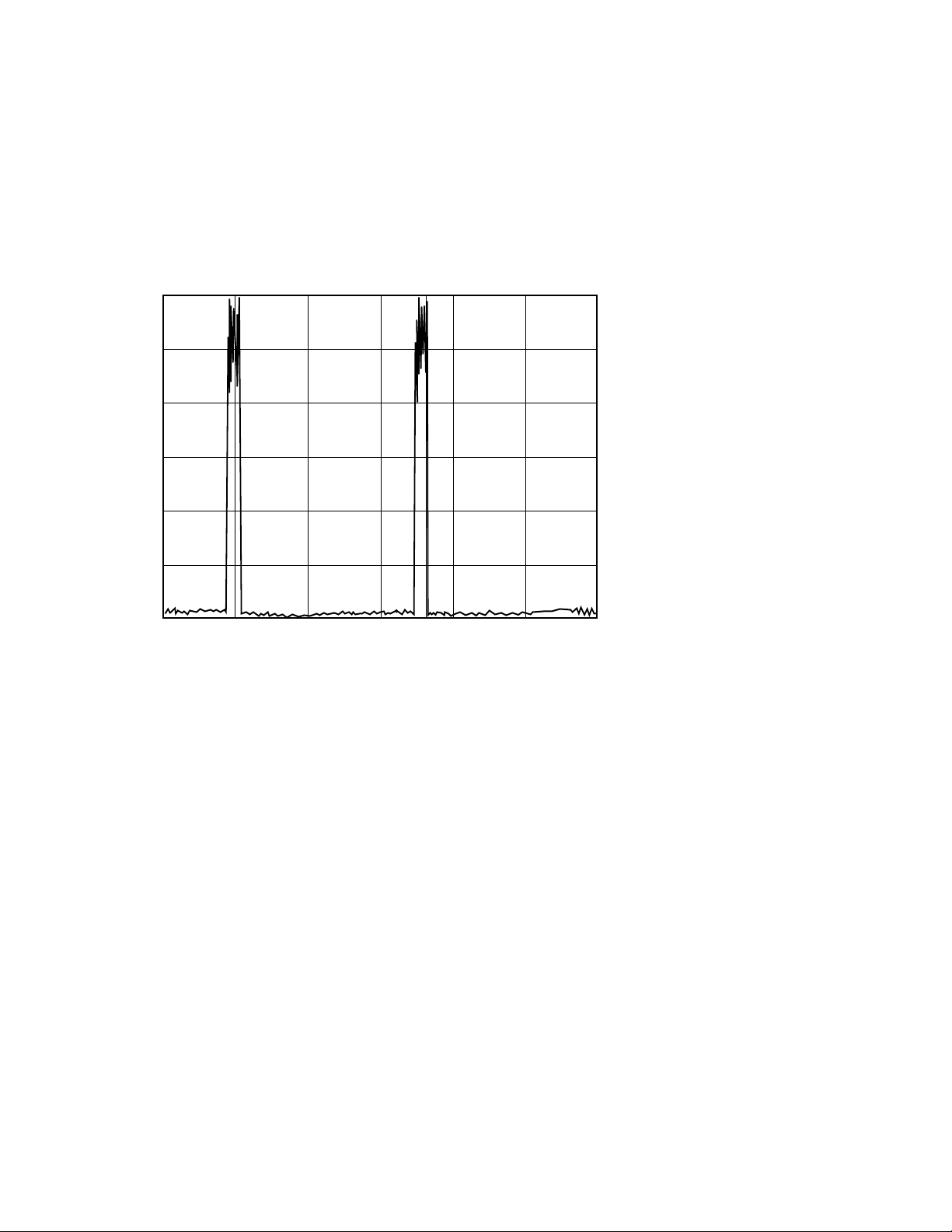
Some cellular phones enter a “wake
up” state every few seconds for a
short period to check for any incoming calls, drawing an active-mode current level.
Between these periods the cellular
phone drops back into a “sleep” state,
drawing only millamperes of current.
This uses less average current than
continuous standby operation, providing longer operating time. This is
referred to as slotted-mode, which is
standard for narrow band CDMA format. Slotted-mode current drain is
illustrated in Figure 7.
Considerations are the same as for
talk-mode current drain. However,
standby-mode pulsed current drain
presents more of a challenge due to
the longer periods, lower duty cycles,
higher crest factors, and lower levels
of current involved. Factors to consider in addition to those of talkmode are:
• Sub-milliampere measurement
accuracy in presence of high
pulsed currents.
• Extended measurement window
time and resolution of window
time setting suited for slow pulse
rates with very low duty cycles
General-purpose system power supplies and basic system DMMs are not
suited for directly measuring slottedmode standby current, because of
these factors.
Figure 7: Slotted-mode Operation Pulsed Current Drain
Current (A)
Current Waveform
300.00 m
250.00 m
200.00 m
150.00 m
100.00 m
50.00 m
0.00 s
500.00 ms 1.00 s 1.50 s 2.00 s 2.50 s 3.00 s
Page 14

14
C. Off-mode Current Leakage
Measurement
If off-mode leakage current is high, it
can quickly and unexpectedly drain
the battery, leading to user dissatisfaction as well as being systematic of
a potential latent failure mechanism.
Production testing off-mode leakage
current catches random manufacturing and component defects. The offmode current drain is usually under
100 microamperes.
The low-level accuracy needs to be
considered when making off-mode
current drain measurements. A sepa-
rate, low current measurement range
with better than 10 microamperes
accuracy is adequate for this meas-
urement.
Microampere level measurement is
not a feature of general-purpose
power supplies.
D. Battery Charger Current
Measurement
In most designs, the battery charger
current is monitored and controlled
by the mobile device itself. The DUT
is usually calibrated at high and low
current levels for accurate rapid and
trickle charge rates.
Rapid charge rate current is typically
under one ampere. Trickle charge
rate current is tens of milliamperes.
Measurement accuracy of 1% (< 3 milliamperes) should be sufficient for
accurate battery charging calibration.
Providing the power supply has the
ability to sink current and emulate a
battery under charge conditions (see
“Considerations when Loading the
DUT Battery Charger,” part II). It
should then be verified that the
power supply measures high and low
charge rate negative currents to the
required accuracy to properly calibrate the DUT. The accuracy required
at the low level, relative to the fullscale capability needs to be considered.
Page 15

15
The wide range and pulsed current
characteristics are challenging to
measure accurately, even when using
multiple pieces of equipment.
Accurate current measurements dur-
ing production test are fundamental
in assuring proper battery life, cali-
bration, and quality of the mobile
communications device.
The Agilent 66311B/D and 66309B/D
dc sources feature a measurement
system specifically for addressing all
these specialized requirements without the need of additional equipment.
The 66311D and 66309D also have a
separate DVM input channel for independent voltage measurements at the
DUT fixture.
Summary of Considerations when Making DUT Power Measurements
Measurement factor Target accuracy Considerations
Talk-mode, DC average current < 3 mA or 1% The measurement system handles high crest factors.
The measurement window can be set to measure exactly one or more pulse
periods, when the pulse rate is known precisely.
The measurement system can alternately provide accurate measurement,
when the pulse rate is not known precisely.
Measurement accuracy is over a full 2 to 3 ampere range.
Talk-mode, peak and high level currents < 20 mA or 3% Peak and high-level measurement capability is actually suited for
the application.
Continuous standby-mode DC Ave. current < 1 mA or 1 to 3% Demanding accuracy requirement relative to full-scale current capability
Slotted standby-mode DC average current < 0.5 mA or 1 to 3% As per talk- and continuous standby-modes
Sub-milliampere measurement accuracy in presence of high pulsed currents
Low pulse rate and duty cycle requires long measurement period and precise resolution.
Off-mode DC average current < 10 uA or 5 to 10% Accuracy requirement at microamperes current level
Charge-mode DC average current < 3 mA or 0.5% Demanding negative polarity current measurement relative to full-scale
current capability
Page 16

By internet, phone, or fax, get assistance
with all your test and measurement needs.
Online Assistance
www.agilent.com/find/assist
Phone or Fax
United States:
(tel) 1 800 452 4844
Canada:
(tel) 1 877 894 4414
(fax) (905) 206 4120
Europe:
(tel) (31 20) 547 2323
(fax) (31 20) 547 2390
Japan:
(tel) (81) 426 56 7832
(fax) (81) 426 56 7840
Latin America:
(tel) (305) 269 7500
(fax) (305) 269 7599
Australia:
(tel) 1 800 629 485
(fax) (61 3) 9272 0749
New Zealand:
(tel) 0 800 738 378
(fax) (64 4) 495 8950
Asia Pacific:
(tel) (852) 3197 7777
(fax) (852) 2506 9284
Product specifications and descriptions in this
document subject to change without notice.
Copyright © 1999, 2000 Agilent Technologies
Printed in U.S.A. 6/00
5968-2424E
 Loading...