

Page 1

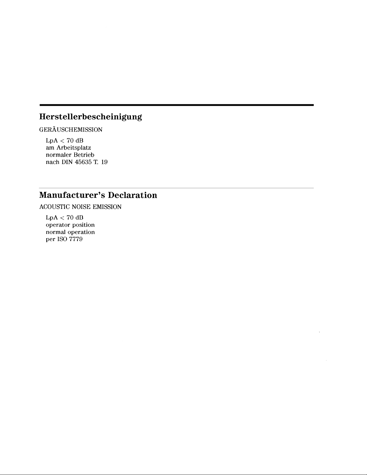
Caution
Use the following procedure when turning off the 42841A:
1. Turn off the DC bias current output.
2. Disconnect a DTU (Device Under Test) from the test fixture.
3. Turn off the 42841A LINE ON/OFF switch.
If turning off the 42841A power with a DUT connected, the 42841A
internal circuit m ay be damaged.
Page 2

Page 3
Page 4

Page 5
Page 6

Page 7

Safety Summary
When you notice any of the unusual conditions listed below, immediately
terminate operation and disconnect the power cable.
Contact your local Agilent Technologies sales representative or
authorized service company for repair of the instrument. If you continue
to operate without repairing the instrument, there is a potential fire or
shock hazard for the operator.
n Instrument operates abnormally.
n Instrument emits abnormal noise, smell, smoke or a spark-like light
during the operation.
n Instrument generates high temperature or electrical shock during
operation.
n Power cable, plug, or receptacle on instrument is damaged.
n Foreign substance or liquid has fallen into the instrument.
Page 8

Page 9
Agilent
42841A BIAS
CURRENT SOURCE
OPERATION
SERIAL
This
NUMBERS
man
ual
applies
directly
2915J
F
or additional
\Serial
Num
b
imp
er"
ortan
in
Chapter
t
information
MANUAL
to
instrumen
4
of
this
ab
out
Man
ts
ual.
with
serial
serial
n
um
b
n
ers,
um
b
er
read
prex
Agilent Part No. 42841-90010
Printed in JAPAN March 2000
Fifth Edition
Page 10
Notice
The
information con
without notice.
This
do
cumen
cop
yrigh
t.
All
photocopied,
the
prior
written
tained in
t
con
tains
righ
ts
are
reproduced,
consen
this do
proprietary
reserv
ed.
or translated
t
of
the
Agilen
cument
information
No part
to another
t
T
ec
is sub
ject to
that
of this
documen
language
hnologies.
c
hange
is
protected
tma
y
without
b
y
b
e
Agilent
Comp
1-3-2,
Hyogo,
Tec
hnologies Japan,
onen
t
T
est
PGU-Kob
Murotani,
Nishi-ku,
651-2241 Japan
Ltd.
e
Kob
e-shi,
c
Copyright 1989, 1991, 1996, 2000 AgilentTechnologies Japan, Ltd.
Page 11
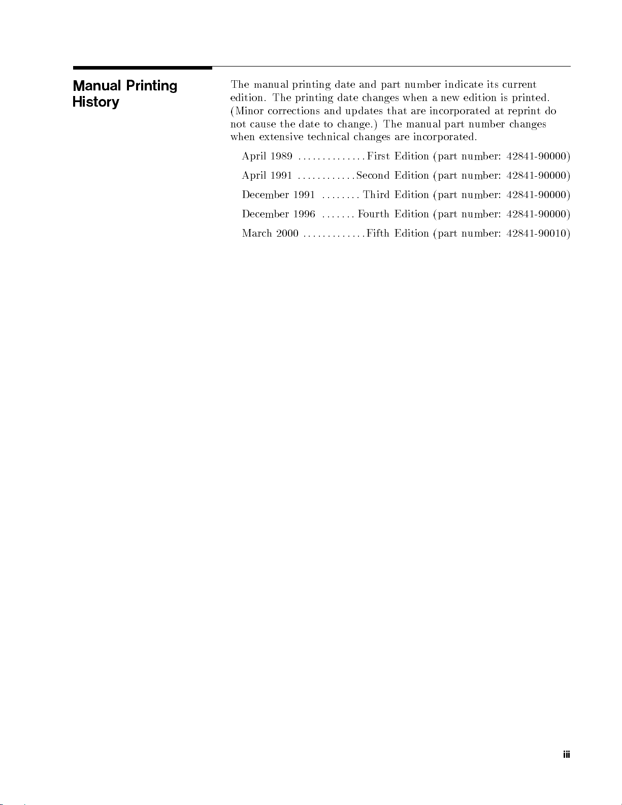
Manual
History
Printing
The
man
ual
prin
ting
edition.
The prin
(Minor corrections
not
cause
the
date
when
extensive
April
April
1989
1991
technical
:
:
:
:
:
:
date
ting date
and up
to
c
hange.) The
:
:
:
:
:
:
:
:
:
:
::
::
and
part
changes
dates
that
changes
:
:
:
:
::
Second Edition
are incorp
First
Edition (part
num
ber
when a
are
manual
indicate its
new edition
incorp
orated
part n
orated.
num
(part
n
umb
um
current
is prin
at
reprin
er c
ber:
42841-90000)
b
er:
42841-90000)
ted.
t
hanges
do
Decem
Decem
Marc
h
ber
b
er
2000
1991
1996
:
::
::
:
::
:
:
:
:
:
Third
:
:
:
:
:
:
:
F
::
:
:
:
:
:
:
ourth
Fifth
Edition
Edition
Edition
(part
(part
(part
n
um
num
n
um
b
er:
42841-90000)
ber:
42841-90000)
b
er:
42841-90010)
iii
Page 12
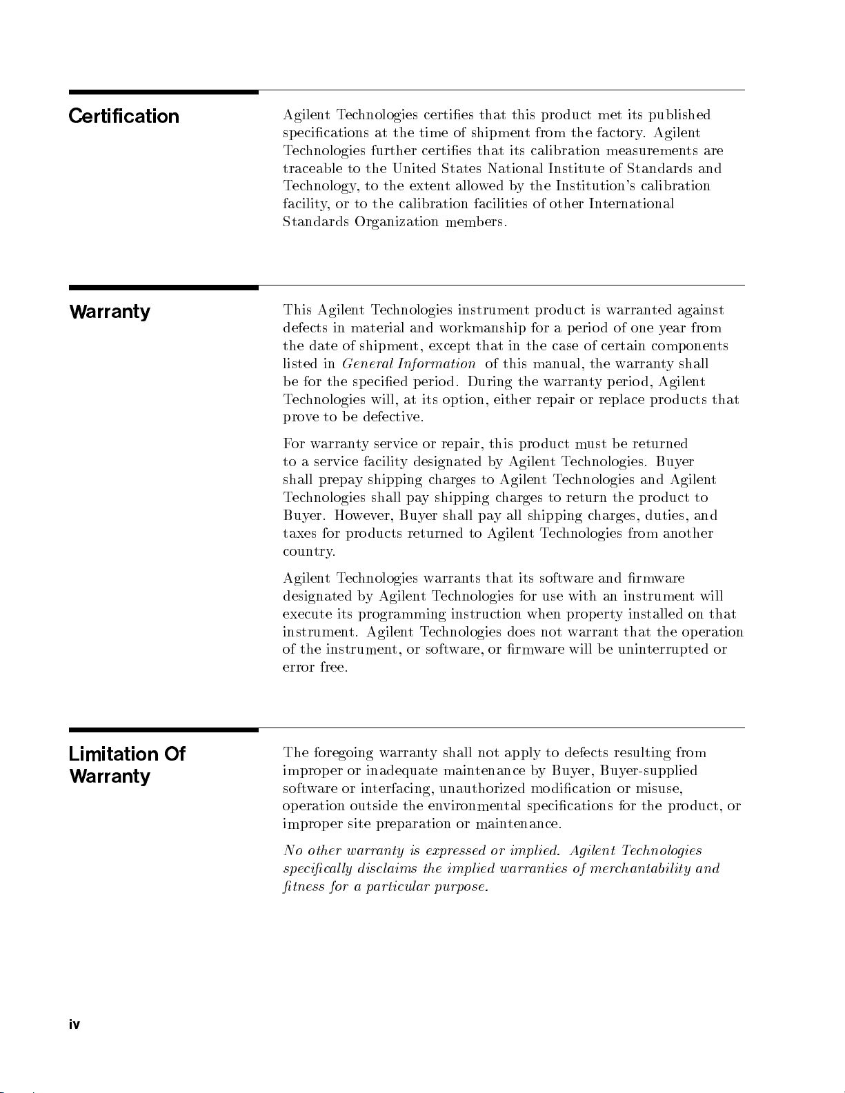
Certification
W
arranty
Agilen
sp
Tec
traceable
T
facilit
Standards
This
defects
the
listed
b
T
pro
F
to
shall
T
Buy
taxes
coun
t
T
ec
hnologies
ecications at
hnologies further
to
echnology
,to
y
,
or
to
Organization
Agilent
in
material
date
of
shipmen
in
Gener
e
for
the
sp
ec
hnologies
v
e
to
b
e
or
w
arran
t
a
service
prepa
y
ec
hnologies
er.
Ho
w
for
pro
try
.
certies
the time
certies
the
United
the exten
the
calibration
Tec
hnologies
and
t,
al Information
ecied
defectiv
y
facilit
p
will,
at
e.
service or
y
designated
erio
its
shipping
shall
pa
y
ev
er,
Buy
er
ducts
returned
that
of shipmen
that
States
t allo
wed
facilities
mem
b
instrumen
w
orkmanship
except
d.
that in
During
option,
repair, this
c
harges
shipping c
shall
pa
to
this
its
National
b
y
ers.
of
this
the
either
product
b
y
Agilen
to
Agilen
harges
y
all
Agilen
product
tfrom
the factory
calibration
Institute of
the
Institution's
of
other
t
pro
duct
for
a
p
erio
the case
man
ual,
w
arran
repair
must
t
T
ec
t
T
ec
hnologies
to
return
shipping
t
T
ec
hnologies
met its
measuremen
Standards and
In
ternational
is
w
arran
d
of
of certain
the
w
arran
t
y
p
erio
or
replace
b
e
hnologies.
the
charges,
from
published
. Agilen
calibration
ted
against
one
y
ear
comp
t
y
shall
d,
Agilen
pro
ducts that
returned
Buy
and
Agilen
pro
duct
duties,
another
t
ts
from
onen
er
to
and
are
ts
t
t
Limitation Of
Warranty
Agilen
designated
execute
instrument.
of
error
The foregoing w
improper or inadequate main
softw
operation outside the en
t
the
instrumen
free.
are or in
Tec
hnologies
b
y
Agilen
its
programming
Agilent
w
arran
ts
that
t
T
ec
hnologies
instruction
T
ec
hnologies
t, or
softw
are, or
arrant
y shall not apply to defects resulting from
tenance b
terfacing, unauthorized modication or
vironmental specications for the product, or
improper site preparation or main
No other warr
spe
cically disclaims the implie
anty is expr
essed or implie
d warr
tness for a particular purpose.
its
soft
for
use with
when
do
es
not
rmw
are
yBuy
tenance.
d. A
anties of mer
w
are
prop
w
arran
will
er, Buy
gilent T
and
ert
b
rm
w
are
an instrumen
y
installed
t
that
the
op
e
unin
terrupted
er-supplied
misuse,
echnologies
chantability and
t
will
on
that
eration
or
iv
Page 13
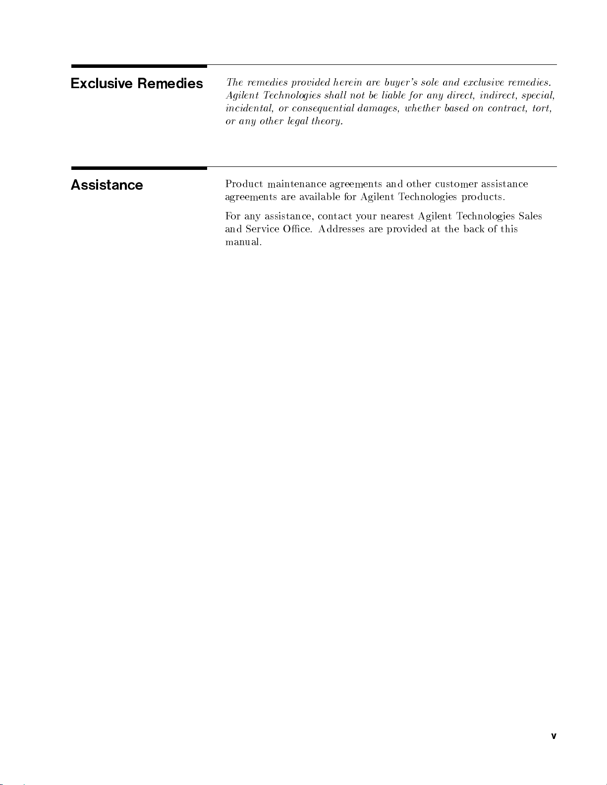
Exclusiv
e
Assistance
Remedies
The
r
eme
dies
A
gilent T
echnolo
incidental, or
or
any
other
Pro
duct main
agreemen
F
or
and
an
y
assistance,
Service
ts
manual.
pr
ovide
d
her
ein ar
conse
le
gal
gies shal
the
l not
quential
ory.
tenance agreemen
are
a
v
ailable
Oce.
for
con
tact
Addresses
e buyer's
be
liable for
damages,
ts and
Agilen
y
our
nearest
are
pro
whether
t
T
ec
vided
sole and
any
other
customer
hnologies
Agilen
at the
exclusive r
dir
e
ct,
b
ase
d
pro
t
T
ec
back
indir
e
ct,
on
c
ontr
assistance
ducts.
hnologies
of this
emedies.
sp
e
cial,
act,
tort,
Sales
v
Page 14
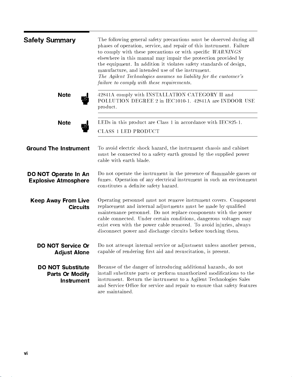
Safety
Summary
The
follo
phases
of op
to comply
elsewhere
the
equipment.
man
ufacture,
The
A
gilent
failur
eto
wing
general
eration, service,
with these
in
this
man
In addition
and
in
T
e
chnolo
comply
with these
safet
y
precautions
ual
ma
y impair
it violates
tended
gies
use
assumes
r
precautions
and repair
or
with
the protection
of
the
instrumen
no liability
e
quir
ements.
m
of this
sp
safety
ust b
e observ
instrument.
ecic
W
standards of
t.
for the
ed during
Failure
ARNINGS
provided
design,
customer's
all
by
Ground
DO
NOT
Explosiv
Keep
Note
Note
The
Operate
e
A
Aw
a
y
Instrument
In
An
tmosphere
From
Liv
Circuits
42841A comply
POLLUTION
pro
LEDs
CLASS
T
o
m
ust
cable
Do
fumes.
constitutes
Op
e
erating
replacemen
main
cable
exist
disconnect
duct.
in
this
1
LED
a
v
oid electric
b
e connected
with
not
op
erate
Op
tenance
connected.
ev
en
DEGREE
pro
PR
earth
eration
a
denite
p
ersonnel
t
and
p
ersonnel.
with
p
o
w
er
with
INST
2
duct
are
Class
ODUCT
shoc
k hazard,
to a
safety
blade.
the
instrumen
of
an
y
electrical
safet
m
ust
in
ternal
adjustmen
Do
Under certain
the
p
o
w
er
and
disc
harge
ALLA
TION
in
IEC1010-1.
1
the
CA
in
accordance
instrumen
earth ground
t
in
the
presence
instrumen
y
hazard.
not
remo
ve
instrumen
ts
m
ust
not
replace
comp
conditions, dangerous
cable remo
ved.
circuits
b
TEGOR
42841A
t
c
b
y
of
t
in
b
e
made
onen
To
av
efore
touc
Y
I
are
with
IEC825-1.
hassis
the
supplied
ammable
suc
h
t
co
v
ers.
b
ts
with
oid
injuries,
hing
I
and
INDOOR
and
cabinet
p
o
gasses
an
en
vironmen
Comp
y
qualied
the
p
voltages
alw
them.
USE
w
er
onen
o
w
may
a
ys
or
t
t
er
DO
NOT Service
Adjust
DO NOT Substitute
Parts Or Modify
vi
Or
Alone
Instrument
Do
not
attempt
capable of
Because of the danger of in
in
ternal
rendering rst
service
aid and
or
adjustmen
resuscitation, is
t
unless
another
present.
troducing additional hazards, do not
p
erson,
install substitute parts or perform unauthorized modications to the
instrumen
and Service Oce for service and repair to ensure that safet
are main
t. Return the instrumen
tained.
t to a Agilen
tT
echnologies Sales
y features
Page 15

Dangerous
Procedure
W
arnings
W
arnings
pro
cedures throughout
warnings
,
suc
must
h
be
as
the
follo
example
this man
w
ed.
b
elo
w, precede
ual. Instructions
poten
tially dangerous
contained
in the
W
arning
Dangerous
instrument.
v
oltages,
Use
this instrument.
capable
extreme
of
caution
causing
when
death,
handling,
are
present
testing,
in
this
and adjusting
vii
Page 16
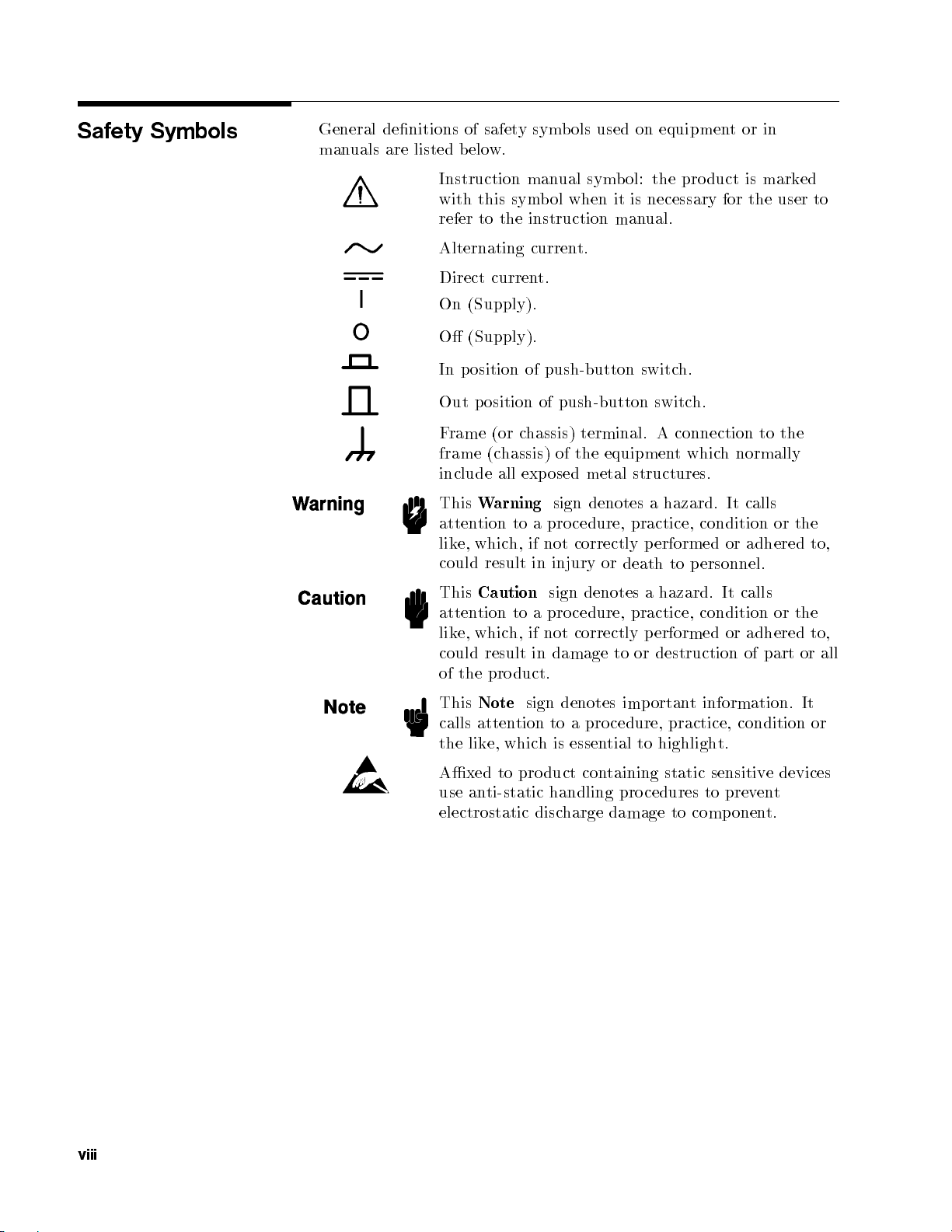
Safety
Symbols
General
man
uals are
denitions
listed b
of
safet
elow.
y
sym
b
ols
used on
equipment
or in
Instruction man
with
this
sym
b
refer
to the
Alternating
Direct
On
(Supply).
O
(Supply).
In
p
osition
Out
p
F
rame
frame
include
This
Warning
atten
tion
lik
e,
whic
could
This
Caution
atten
tion
lik
e,
whic
could
of
the pro
instruction man
curren
curren
osition
(or
(c
result
of
c
hassis)
hassis)
all
exp
to
h, if
t.
push-button
of
a
not correctly
in
to a
h,
if
not
result
in
duct.
pro
pro
ual sym
ol
when
it is
t.
push-button
terminal.
of
the
equipmen
osed
metal
sign
denotes
cedure,
injury
sign
or
denotes
cedure,
correctly
damage
to
b
ol:
the
necessary for
ual.
switc
switc
A
structures.
a
hazard.
practice,
p
erformed
death
a
hazard.
practice,
p
erformed
or
destruction
pro
duct
h.
h.
connection
t
whic
h
It
condition
or
to
p
ersonnel.
It
condition
or
is
mark
the user
to
the
normally
calls
or
the
adhered
calls
or
the
adhered to,
of
part
ed
or
to
to,
all
This
Note
calls
atten
tion
the
lik
e,
whic
Axed
use
to
anti-static
electrostatic
sign
denotes
to
h
is
product
handling pro
disc
harge
a
pro
cedure,
essen
tial
containing
damage
imp
ortan
practice,
to
highligh
static sensitiv
cedures to
t information.
condition
t.
preven
to
comp
onent.
It
or
e devices
t
viii
Page 17
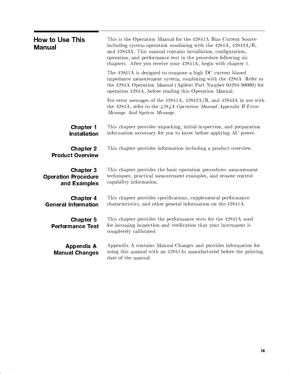
Ho
w
to Use
Manual
This
This
is
the
Op
including
system op
and 42843A.
op
eration,
c
hapters. After
and
eration
eration com
This man
p
erformance
you
receive
Man
ual
ual
con
your
for
tains
test
the 42841A
bining with
installation,
in the
procedure
42841A, b
Bias Curren
the 4284A,
conguration,
following
egin
with
t Source
42842A/B,
six
c
hapter
1.
Product
Operation
and
General
Chapter
1
Installation
Chapter 2
Ov
erview
Chapter
3
Procedure
Examples
Chapter 4
Information
The 42841A
imp
edance
the
4284A
operation
F
or error
the
4284A,
Message
This
4284A, b
messages of
A
c
hapter
measuremen
Op
nd
information
This
c
hapter
This
c
hapter
tec
hniques,
capabilit
This
c
haracteristics,
y
information.
c
hapter pro
is designed
eration
refer
to
System
pro
vides
necessary
pro
vides
pro
vides
practical
vides
and
to comp
t
system,
Man
ual
(Agilen
efore reading
the
42841A,
the
4284A
Message
unpac
for
king,
y
ou to
.
information
the
basic
measuremen
sp
ecications,
other
general
ose a
com
bining
tP
this
Op
42842A/B,
Op
er
ation
initial
kno
w
including
op
eration
t
examples,
supplemen
information
high
DC
with
art Num
eration
Manual
inspection,
b
efore
a
pro
curren
the
ber
Man
and
42843A
App
and preparation
applying
pro
duct
cedures
and
remote
tal
p
erformance
on
the
t
biased
4284A.
Refer
to
04284-90000) for
ual.
in
use
with
endix
B
Err
or
A
C
p
o
w
er.
o
v
erview.
measuremen
con
t
trol
42841A.
Chapter
P
erformance
Appendix
Manual
5
T
est
A
Changes
This
c
hapter
for incoming
completely
App
endix
using
this
A
man
date of the
pro
vides
insp
ection
calibrated.
contains
ual
with
manual.
the
p
and
Manual
an
42841As
erformance
v
erication
Changes and
manufactured
tests
that
for
the
y
our
provides
b
42841A
instrumen
information
efore
the
used
t
is
prin
for
ting
ix
Page 18
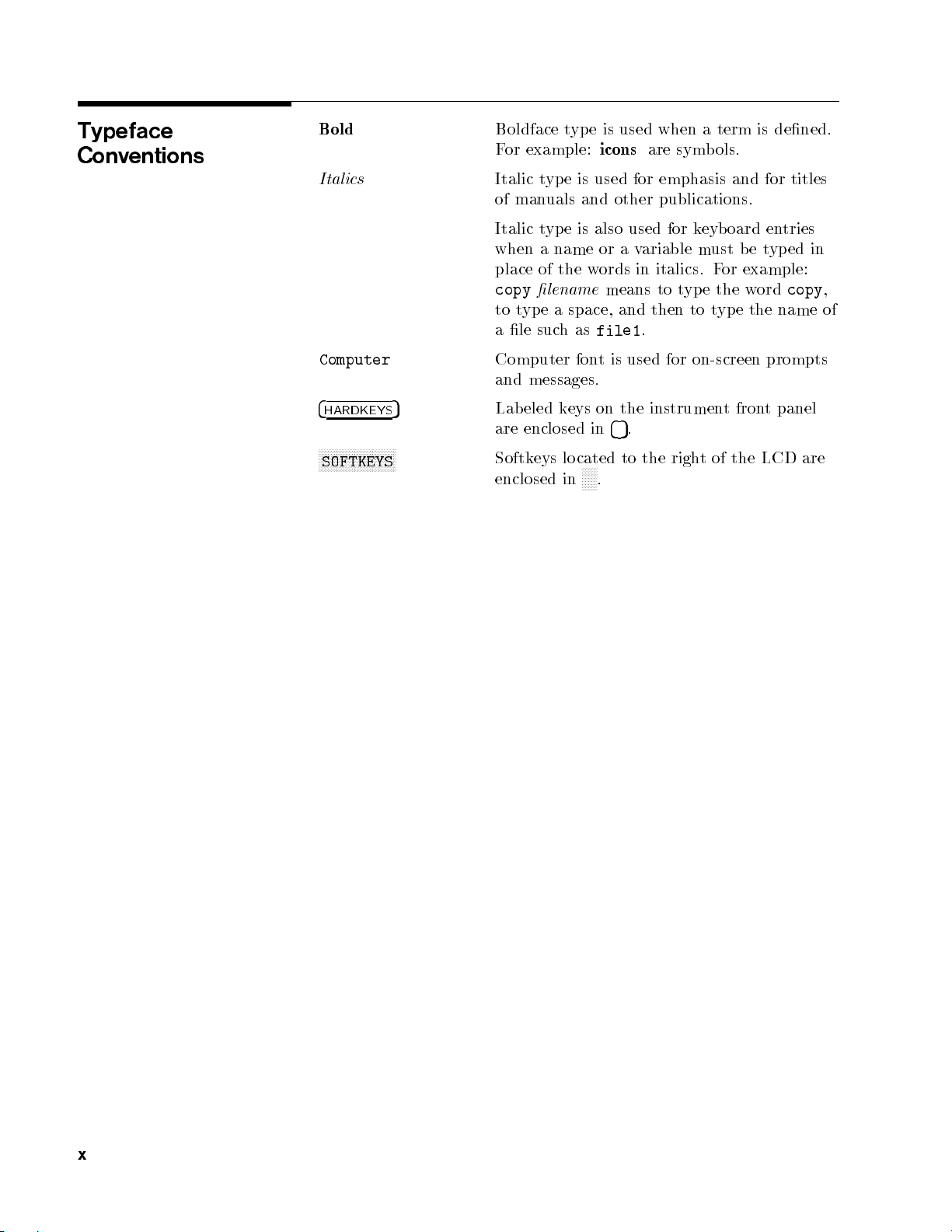
Typeface
Conv
entions
Bold
Italics
Boldface
F
or example:
Italic
typ
of
man
uals
Italic
t
yp
when a
place
copy
to t
a
ype
le
name or
of
the
lename
a space,
suc
h
t
yp
e
is
used
when
aterm
icons
e
is
used
and
e
is
also
w
ords
as
file1
for
other
used
av
in
means
and
are
symb
emphasis
publications.
for
k
eyboard
ariable m
italics.
to
t
yp
e
then
to
.
ols.
and
ust
F
or
the w
t
yp
e
is dened.
for
entries
b
e
t
yp
ed
example:
ord
copy
the
name
titles
in
,
of
Computer
4
HARDKEYS
N
N
N
N
N
N
N
N
NN
N
N
N
N
N
N
N
N
N
N
SOFTKEYS
Computer
fon
t
is
used
for
on-screen prompts
and messages.
5
N
N
N
N
N
N
Lab
eled
are
enclosed
Softkeys
enclosed
k
lo
in
eys
cated
N
N
on
the
instrumen
5
.
in
4
to
the
N
N
N
righ
t
fron
t panel
t
of
the
LCD
are
.
x
Page 19
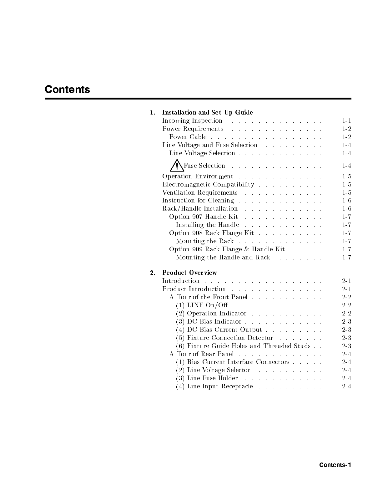
Contents
1.
Installation and
Incoming
P
o
w
P
Line
Line
Op
eration
Electromagnetic Compatibilit
V
entilation
Instruction
Rac
Option
Option
Option
Insp
er
Requiremen
ow
er Cable
V
oltage
V
oltage
F
use
k/Handle
907 Handle
Installing
908
Moun
909
Moun
Set Up
ection
ts
.
.
and
F
use
Selection
Selection
En
vironmen
Requirements
for
Cleaning
Installation
the
Handle
Rac
k
ting
the
Rac
Rac
k
ting
the
Handle
Guide
.
. .
.
.
Selection
.
t
Kit
Flange
k
Flange
.
.
.
. .
.
.
.
.
.
. .
.
.
.
.
.
.
y
. .
.
.
.
.
.
.
.
.
.
Kit
.
.
.
&Handle
and
Rac
.
. .
.
.
. .
.
.
.
.
.
.
.
.
.
.
.
. .
.
.
.
.
.
.
. .
.
.
k
.
. .
.
.
.
.
.
.
. .
.
.
.
.
Kit
.
.
.
. .
.
.
.
.
.
.
. .
.
.
.
.
.
.
.
.
.
.
.
. .
.
.
.
.
.
.
.
.
. .
.
.
.
.
.
.
.
.
.
.
.
.
.
.
. 1-4
.
.
.
.
.
.
.
.
.
.
.
.
.
.
.
.
.
.
.
.
.
.
.
.
.
. .
. .
.
.
.
.
.
.
.
.
.
.
.
.
.
.
.
.
.
.
.
. 1-7
.
.
.
.
.
.
.
.
.
.
.
.
.
.
. 1-7
1-1
1-2
1-2
1-4
1-4
1-5
1-5
1-5
1-6
1-6
1-7
1-7
1-7
1-7
2.
Pro
duct
Ov
erview
In
tro
duction
Pro
duct In
A
T
our
(1)
(2)
(3)
(4)
(5)
(6) Fixture Guide Holes and Threaded Studs .
AT
our of Rear P
(1) Bias Curren
(2) Line V
(3) Line F
(4) Line Input Receptacle
.
.
troduction
of
the
LINE
On/O
Operation
DC
Bias
DC
Bias
Fixture
Connection
oltage Selector
use
.
.
.
.
.
.
.
.
.
.
. .
.
.
.
.
.
.
F
ron
t
Panel
.
Indicator .
Indicator
Curren
anel .
tIn
Holder . . . . . . . . . . . . 2-4
. .
. .
.
.
.
.
.
.
.
.
.
.
.
.
. .
. .
. .
t
Output
. .
terface Connectors .
.
.
.
Detector .
. . . . . . . . . . 2-4
. . . . . . . . .
. . . . . . . . . . 2-4
.
.
.
.
. .
.
.
.
.
.
.
.
.
.
.
.
.
.
.
. .
.
.
.
.
.
. .
.
.
.
. .
. .
. .
.
.
.
.
.
. . . . 2-4
2-1
.
.
.
.
.
. 2-3
. 2-4
2-1
2-2
2-2
2-2
2-3
2-3
2-3
Contents-1
Page 20
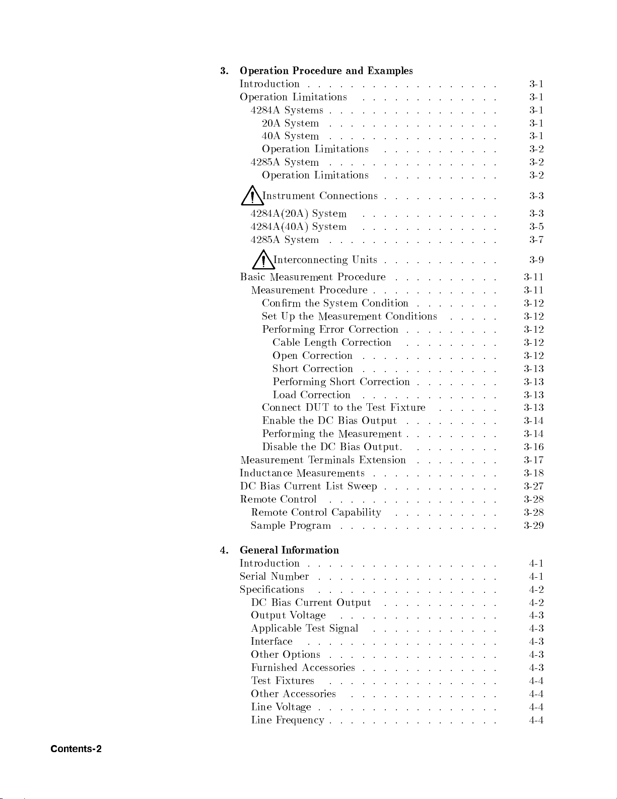
3. Op
eration Pro
In
tro
Op
eration
4284A Systems
4285A
cedure and
duction
20A
40A
Op
eration
Op
eration Limitations
.
.
Limitations
System
System .
Limitations
System
.
. .
.
.
.
.
. .
.
.
.
.
.
Examples
.
.
.
. .
. .
.
.
.
.
. .
. .
. .
.
.
.
.
. .
.
.
. .
.
. .
. .
. .
.
. .
.
. .
.
. .
.
. .
. .
. .
.
.
.
.
.
. .
.
.
. .
.
. .
. .
.
.
.
.
.
. .
.
.
. .
.
. .
. .
. .
.
.
.
. .
.
.
.
.
. 3-1
. 3-1
. 3-1
3-1
.
.
.
.
3-1
3-2
3-2
3-2
Instrumen
4284A(20A)
4284A(40A)
4285A
Basic
Measuremen
Measuremen
Inductance
DC
Remote
Remote
Sample Program
System
In
terconnecting Units
Measuremen
Conrm
Set
Up
the
P
erforming
Cable Length
Op
en
Short
P
erforming
Load
Correction
Connect
Enable
P
Disable
Bias
the
erforming
the
t
Measurements
Curren
Con
trol
Control
t
Connections
System
System .
.
.
.
t
Pro
cedure
t
Pro
cedure
the
System Condition
Measuremen
Error
Correction
Correction .
Correction
Correction
Short
DUT
to
the
DC
Bias
the
Measurement
DC
Bias
T
erminals
t
List
Sw
.
.
.
Capabilit
. .
.
.
.
.
.
.
. .
.
.
.
.
.
. .
.
.
.
.
t
Conditions
.
.
.
.
.
.
.
.
Correction
.
.
.
.
T
est
Fixture
Output
Output.
Extension
. .
.
eep .
.
. .
. .
.
.
.
y
.
. .
.
. .
.
.
. .
.
.
.
. .
.
. .
.
. .
.
.
.
. .
.
.
.
.
. .
. .
.
.
.
.
.
.
.
.
. .
.
.
.
. .
.
.
.
.
.
.
. .
.
.
.
.
.
.
.
.
.
.
. .
.
.
.
.
.
.
. .
.
.
.
.
.
.
.
.
.
.
.
.
. .
.
.
. .
.
.
.
.
.
.
.
.
.
.
.
.
.
.
.
.
.
.
.
.
.
. .
.
.
.
.
.
.
.
.
.
.
.
.
.
.
.
.
.
.
.
.
. .
.
.
. .
.
. .
.
. .
.
.
.
.
.
.
.
.
.
.
.
.
. .
.
.
.
.
.
. .
.
.
.
.
. .
.
.
.
.
.
.
.
.
.
.
.
.
. .
.
.
3-3
.
.
. 3-7
.
. 3-11
.
.
.
.
.
.
.
.
.
.
.
. 3-16
.
.
.
.
.
3-3
3-5
3-9
3-11
3-12
3-12
3-12
3-12
3-12
3-13
3-13
3-13
3-13
3-14
3-14
3-17
3-18
3-27
3-28
3-28
3-29
Contents-2
4. General Information
Introduction .
Serial
Specications
Number
DC Bias Curren
Output V
Applicable T
Interface . . . . . . .
Other Options . . . . . . . . . . . . . . . . 4-3
Furnished Accessories . . . . . . . . . . . . . 4-3
Test Fixtures . . . . . . . . . . . . . . . . 4-4
Other Accessories . . . . . . . . . . . . . . 4-4
Line Voltage . . . . . . . . . . . . . . . . . 4-4
Line Frequency . . . . . . . . . . . . . . . . 4-4
. . . . . . .
. . . . . . . . . . . . . . . . . 4-1
. . . . . . . . . . . . . .
t Output
oltage .
est Signal
. . . . . . . . . . . . . . 4-3
. . . . . . . . . . 4-1
. . . 4-2
.
. . . . . . . . . . 4-2
. . . . . . . . . . . . 4-3
. . . . . . . . . . . 4-3
Page 21
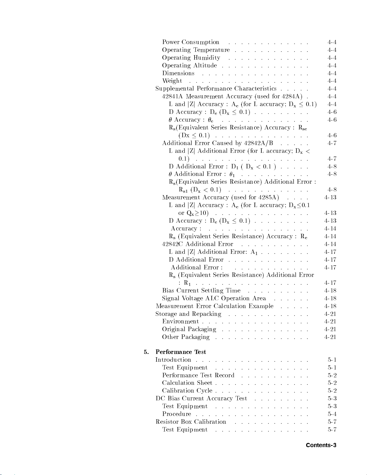
Po
wer
Consumption .
Op
erating
Op
erating
Operating
Dimensions
W
eight
Supplemen
42841A
L
D
Rs(Equiv
Additional
L
D
Rs(Equiv
Measuremen
L
D
Rs(Equiv
42842C
L
D
Rs(Equiv
Bias
Signal
Measurement
Storage
En
vironmen
Original P
Other
. .
tal
Measuremen
and
j
Accuracy
Accuracy
(Dx
and
j
0.1)
Additional
Additional
Rs1(Dx<
and
j
or
Q
Accuracy
Accuracy
Additional
and
j
Additional
Additional Error
:
R
1
Curren
V
oltage
and
Packaging . . . . . . . . . . . . . . . 4-21
. .
. .
T
emp
erature
Humidit
Altitude .
.
.
.
. .
. .
P
erformance
Z
j
Accuracy :
:
D
e(Dx
:
e
alent
Series Resistance)
0.1)
.
Error
Caused
Z
j
Additional
.
.
.
.
Error
Error
alen
t
Series
0.1) .
t
Accuracy
Z
j
Accuracy
10)
x
alen
Z
j
alen
.
t
Error Calculation
Repac
t
ackaging . . . . . . .
.
:
D
e(Dx
:
.
.
t
Series
Additional
Error
t
Series Resistance)
.
. .
Settling
ALC
king
.
.
.
.
y .
. .
.
.
.
.
. .
. .
Characteristics
t
Accuracy
A
e
.
.
.
.
.
.
b
Error
.
.
.
:
D
1
:
1
Resistance)
. .
(used
:
A
e
.
.
.
.
.
.
Resistance)
Error .
Error:
.
.
:
.
. .
. .
Time
Op
eration
.
. .
.
.
.
.
.
. .
.
.
. .
.
.
(for
0.1)
.
.
.
.
y
42842A/B
(for
.
.
(
D
x
.
.
.
for
(for
.
.
0.1)
.
.
.
A
.
.
.
.
. .
.
Area
Example .
. .
.
.
.
.
.
.
.
.
.
.
.
.
.
. .
. .
. .
. .
. .
. .
.
.
.
.
.
.
.
. .
. .
. .
. .
. .
.
.
.
.
.
.
.
.
.
.
.
.
(used
for
4284A
)
L accuracy;
.
.
.
.
.
.
. .
. .
Accuracy
.
.
.
.
.
. .
L
accuracy;
.
.
.
.
.
<
0.1
)
.
.
. .
.
.
Additional
.
.
.
.
.
4285A
) .
L
accuracy;
.
.
.
.
.
.
.
. .
.
.
.
. .
.
Accuracy
.
.
.
.
.
.
.
.
1
.
.
.
. .
.
.
.
.
. .
.
.
.
.
.
.
.
Additional Error
.
.
.
.
.
.
.
.
. .
.
.
.
. . . . . . . 4-21
D
.
. .
.
. .
.
.
.
D
.
.
.
.
.
.
.
.
. .
.
. .
. .
.
x
.
:
R
. .
. .
D
.
.
Error
.
. .
x
.
.
.
:
.
.
.
.
.
.
.
.
. .
se
x
. .
.
.
.
0.1
.
.
.
R
.
.
.
.
.
. .
.
.
. .
.
.
. 4-4
.
.
. 4-4
0.1) 4-4
.
. 4-6
. 4-7
<
.
.
.
.
.
.
.
e
.
.
.
.
.
.
.
.
4-4
4-4
4-4
4-4
4-4
4-4
4-6
4-6
4-7
4-8
4-8
:
4-8
4-13
4-13
4-13
4-14
4-14
4-14
4-17
4-17
4-17
4-17
4-18
4-18
4-18
4-21
4-21
5.
Performance T
Introduction .
Test Equipmen
Performance T
Calculation Sheet . . . . . . . . . . . . . . . 5-2
Calibration Cycle . . . . . . . . . . . . . . . 5-2
DC Bias Current Accuracy Test . . . . . . . . . 5-3
Test Equipment . . . . . . . . . . . . . . . 5-3
Procedure . . . . . . . . . . . . . . . . . . 5-4
Resistor Box Calibration . . . . . . . . . . . . 5-7
Test Equipment . . . . . . . . . . . . . . . 5-7
est
. . . . . . . . . . . .
t . .
est Record
. . . . . . . . . . . . . 5-1
. . . . . . . . . . . 5-2
. . . . . 5-1
Contents-3
Page 22

Calicuation
P
A.
Man
In
Man
Index
Procedure
erformance
ual
Changes
tro
duction .
ual Changes
. .
. .
Sheet
.
T
est Record
. .
. .
.
. .
. .
.
.
.
. .
.
. .
.
. .
.
.
. .
.
.
.
. .
.
.
.
. .
.
.
.
. .
.
.
.
. .
.
.
. .
. .
.
.
.
.
.
.
. .
. .
. .
. .
.
.
.
.
.
.
.
.
.
.
5-7
5-9
5-11
A-1
A-1
Contents-4
Page 23
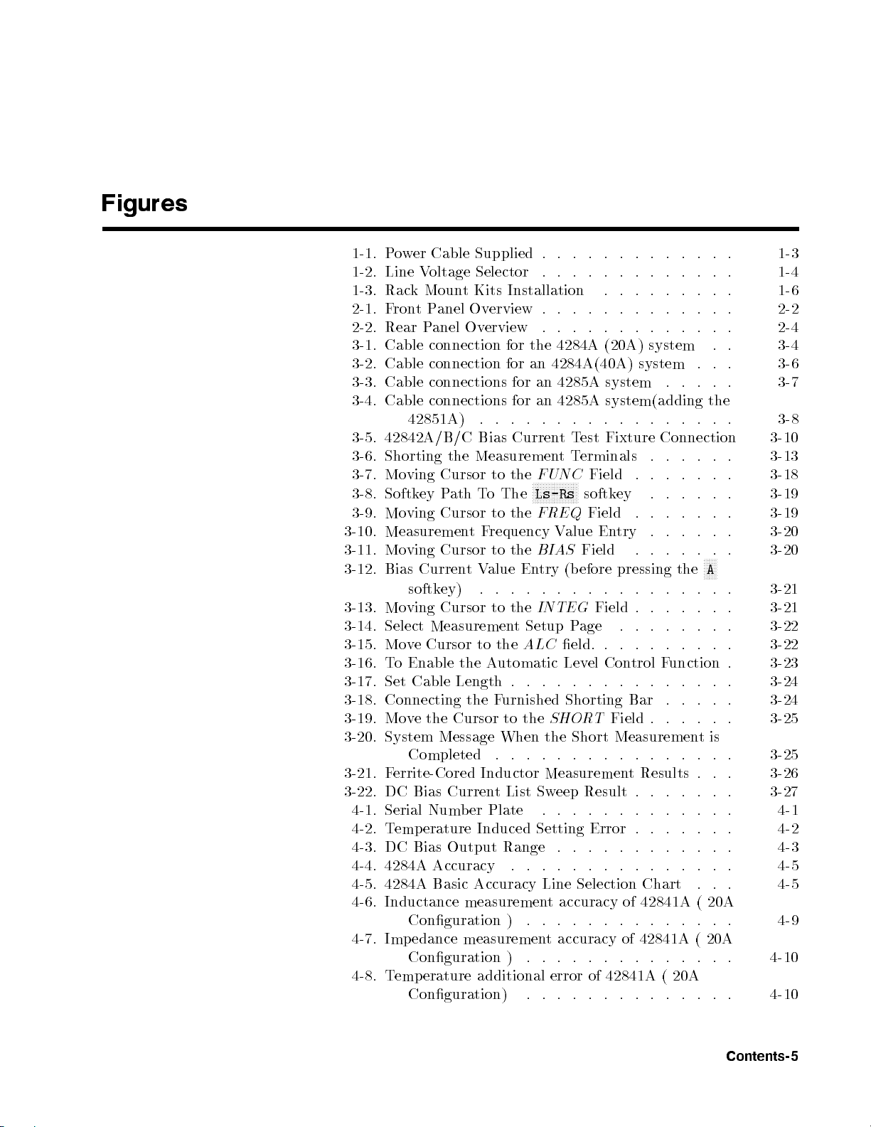
Figures
1-1. P
ow
er
Cable
1-2.
Line
V
oltage
1-3.
Rac
k
Mount
2-1. F
ron
t
P
2-2.
Rear
P
anel
3-1.
Cable
3-2.
Cable
3-3.
Cable
3-4.
Cable
3-5.
42842A/B/C
3-6.
Shorting
3-7. Mo
3-8. Softk
3-9.
Mo
3-10.
Measuremen
3-11.
Mo
3-12.
Bias
3-13.
Moving
3-14.
Select
3-15.
Mo
3-16.
T
3-17.
Set
3-18.
Connecting
3-19.
Mo
3-20. System
3-21. F
3-22. DC Bias Curren
4-1. Serial Num
4-2. T
4-3. DC
4-4. 4284A Accuracy
4-5. 4284A Basic Accuracy Line Selection Chart
4-6. Inductance measuremen
4-7. Imp edance measurement accuracy of 42841A ( 20A
4-8. Temperature additional error of 42841A ( 20A
connection
connection
connections
connections
42851A) .
ving Cursor
ey
ving
ving
Curren
softk
Measuremen
v
e
Cursor
o
Enable
Cable Length
v
e
the
Completed
errite-Cored Inductor Measuremen
emperature Induced Setting Error .
Bias Output Range
Conguration ) . . . . . . . . . . . . . . 4-9
Conguration ) . . . . . . . . . . . . . . 4-10
Conguration) . . . . . . . . . . . . . . 4-10
Supplied
Selector
Kits Installation
anel
Ov
erview
Ov
erview
for the
for
for
for
.
.
Bias
Curren
the
Measuremen
to
the
P
ath
T
o
The
Cursor
Cursor
ey)
Cursor
Message When
to
t
F
requency
to
t
V
alue
.
.
to
to
the
the
Automatic
the
F
Cursor
.
t List Sw
ber Plate
the
the
En
.
the
t
ALC
. .
urnished
to
the
.
. . . . . . . . . . . . . .
.
.
.
.
.
.
.
.
.
.
.
.
.
.
.
.
.
.
. .
. .
. .
. .
.
.
.
.
.
.
.
.
.
.
.
.
.
.
.
.
.
.
.
.
. .
. .
. .
4284A (20A)
an
4284A(40A)
an
4285A
an
4285A
.
.
.
.
.
.
t
T
est
Fixture
t
T
erminals
FUNC
N
N
N
N
N
Ls-Rs
FREQ
BIAS
try
.
.
INTEG
Setup
. .
the Short
. .
. . . . . . . . . . . . . 4-1
Field
N
N
N
N
N
NN
NN
N
N
N
softk
Field
V
alue
En
Field
(b
efore
.
.
.
.
Field
P
age .
eld.
.
Lev
el
Con
.
.
.
Shorting
SHOR
T
. .
. .
eep
Result .
. . . . . . . . . . . . 4-3
t accuracy of
system .
system
system
system(adding
.
ey
try
pressing
.
.
.
Field
Measuremen
. .
.
.
.
.
.
.
Connection
.
.
.
.
.
.
.
.
.
.
.
.
.
.
.
.
.
.
.
.
.
the
.
.
.
.
.
.
.
.
. .
.
.
.
.
. .
trol
F
unction
.
.
.
.
Bar
.
.
.
.
.
. .
. .
t Results .
. . . . . . 3-27
. . . . .
42841A ( 20A
.
.
.
.
.
.
.
.
.
N
N
A
.
.
.
. .
.
. .
.
t
. . . 4-5
.
.
. .
.
.
.
.
.
.
.
.
.
.
the
.
.
.
.
.
.
.
.
.
.
. .
.
.
N
N
N
. .
.
.
.
.
.
.
.
.
. 3-24
.
. 3-25
is
. .
. . 3-26
. 4-2
. 4-5
1-3
1-4
1-6
2-2
2-4
3-4
3-6
3-7
3-8
3-10
3-13
3-18
3-19
3-19
3-20
3-20
3-21
3-21
3-22
3-22
3-23
3-24
3-25
Contents-5
Page 24
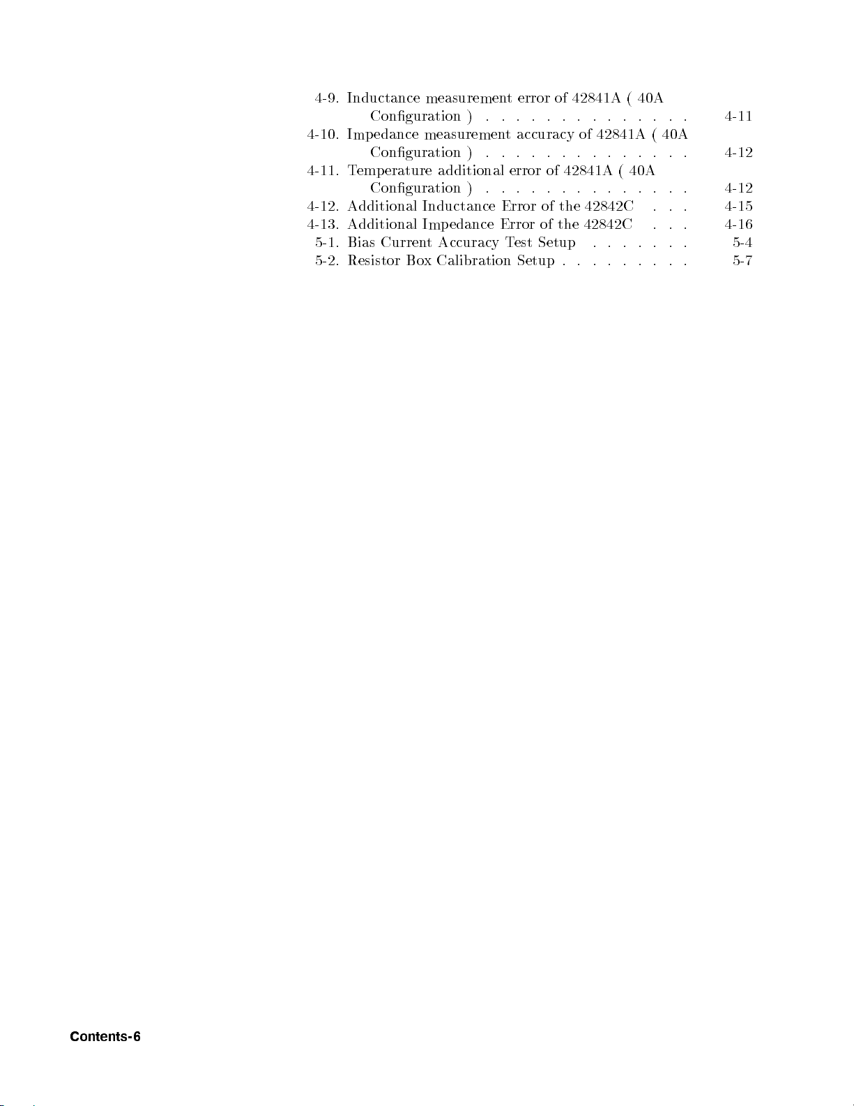
4-9. Inductance
Conguration
4-10.
Imp
edance
Conguration )
4-11.
T
emp
erature
Conguration
4-12.
Additional
4-13.
Additional
5-1.
Bias Curren
5-2.
Resistor
measurement
measurement
additional
Inductance
Imp
edance
t Accuracy
Bo
x
Calibration
)
) .
.
.
.
accuracy of
. .
.
error
. .
Error
Error
Test
Setup
error of
.
.
.
.
of 42841A
. .
of
of
Setup
42841A (
.
.
.
.
.
.
. .
. .
the
42842C
the
42842C
.
.
.
.
40A
.
.
. .
42841A (
.
.
.
(40A
.
.
.
.
.
.
.
.
.
.
.
. .
.
.
. .
40A
.
.
.
.
.
4-11
. 4-12
.
4-12
.
4-15
. 4-16
.
.
5-4
5-7
Contents-6
Page 25
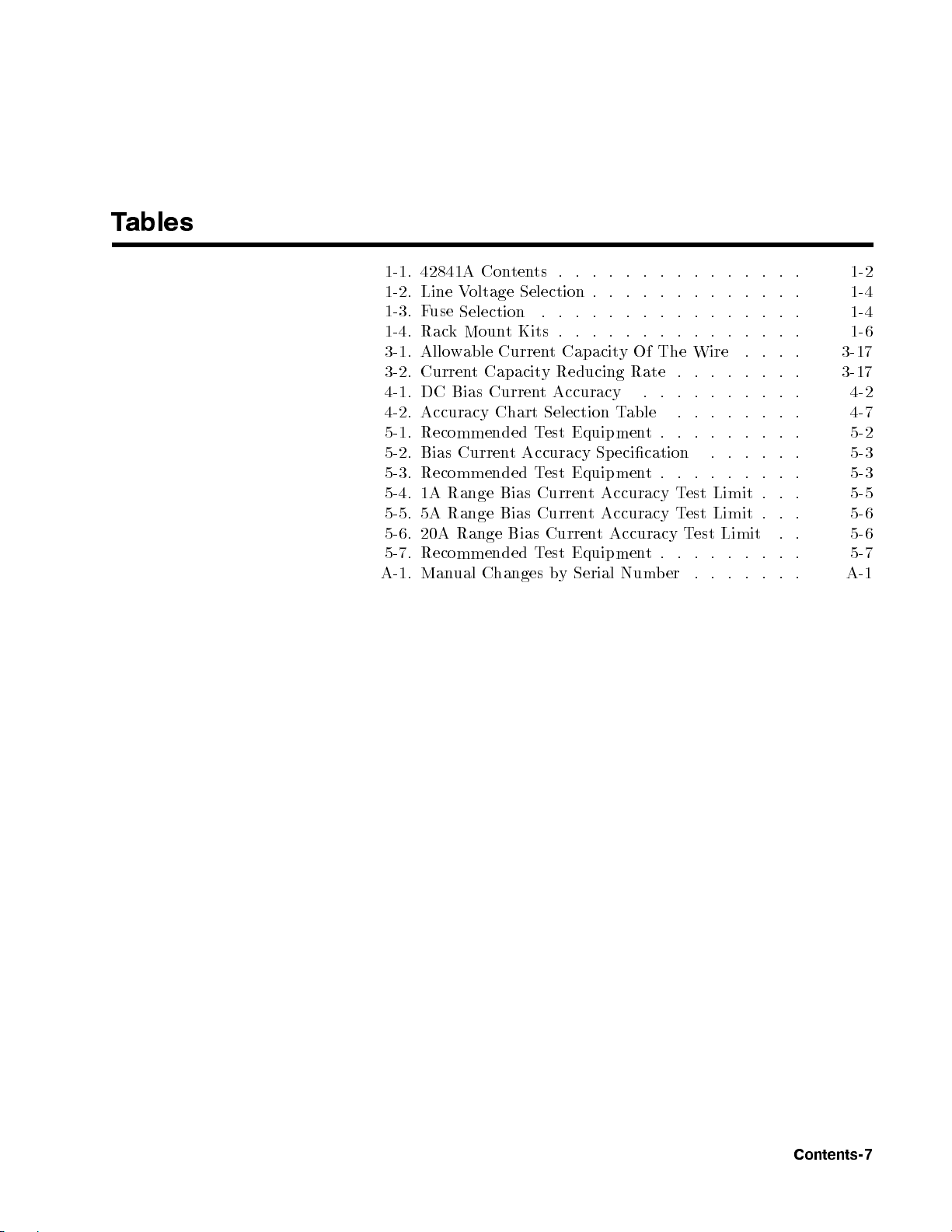
Tables
1-1.
42841A
1-2.
Line
1-3.
F
use
1-4.
Rac
3-1.
Allo
3-2.
Curren
4-1.
DC
4-2.
Accuracy
5-1.
Recommended
5-2.
Bias
5-3.
Recommended
5-4. 1A
5-5.
5A
5-6.
20A
5-7.
Recommended
A-1.
Man
Con
ten
Voltage
Selection
k
Moun
t
Kits
wable
Bias
Current
t
Capacit
Curren
Chart Selection
Curren
t
Range Bias
Range
Range
ual
Changes
Bias
Bias
ts
.
.
Selection .
.
.
.
.
.
Capacity
y
Reducing
t
Accuracy
T
est
Equipmen
Accuracy
T
est
Equipmen
Curren
Curren
Curren
T
est
Equipmen
b
y
Serial
.
.
.
.
. .
. .
.
.
.
.
.
. .
. .
Of
Rate
.
Table
t
Sp
ecication
t
t
Accuracy
t Accuracy
t
Accuracy
t
Num
b
. .
.
The
.
.
.
.
er
. .
.
.
.
.
. .
Wire
.
.
.
. .
.
.
.
.
.
.
T
est
Test
T
est
.
.
.
. .
.
.
.
.
. .
.
.
. .
.
.
.
.
.
.
.
.
Limit
Limit
Limit
.
.
.
.
.
.
.
.
.
.
.
.
.
. .
.
. .
.
.
.
.
.
. .
.
.
.
.
.
.
.
.
.
. .
.
.
.
.
.
.
.
.
.
.
.
.
. 5-3
.
.
.
.
.
.
.
.
. .
.
.
.
1-2
1-4
1-4
1-6
3-17
3-17
4-2
4-7
5-2
5-3
5-5
5-6
5-6
5-7
A-1
Contents-7
Page 26

Page 27
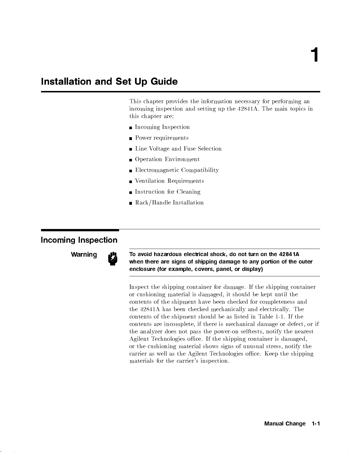
1
Installation and
Incoming
Inspection
Set
Up
Guide
This
c
hapter
incoming
this
Incoming
P
Line
Op
chapter
o
w
er
Voltage
eration
insp
Insp
requiremen
Electromagnetic
V
en
tilation
Instruction
Rac
k/Handle
pro
vides
ection
and
are:
ection
ts
and F
use
En
vironmen
Compatibility
Requiremen
for
Cleaning
Installation
the
information
setting
Selection
t
ts
up
necessary
the
42841A.
for
p
erforming
The main
an
topics in
W
arning
T
o
a
v
oid
hazardous
when
there are
enclosure
Insp
or
cushioning
con
tents
the
42841A
ect
(for
the
of the
shipping
has
contents of the shipmen
electrical
signs
of
shipping
example, co
con
material
is
shipment
b
een c
hec
t should be as listed in T
shock,
vers,
tainer
for
damaged,
hav
eb
k
ed
mec
do
damage
panel, or
damage.
it
een
c
hec
hanically
contents are incomplete, if there is mec
the
analyzer does not pass the po
AgilentT
echnologies oce. If the shipping con
or the cushioning material sho
carrier as w
ell as the Agilen
wer-on selftests, notify the nearest
ws signs of un
tT
echnologies oce. Keep the shipping
materials for the carrier's inspection.
not
turn
on
to
any
portion
display)
If
the
shipping con
should
b
e
k
ept
k
ed
for
completeness
and
electrically
able 1-1. If the
hanical damage
tainer is damaged,
usual stress, notify the
the
42841A
of
the
un
til
the
.
or defect, or if
outer
tainer
and
The
Manual Change 1-1
Page 28
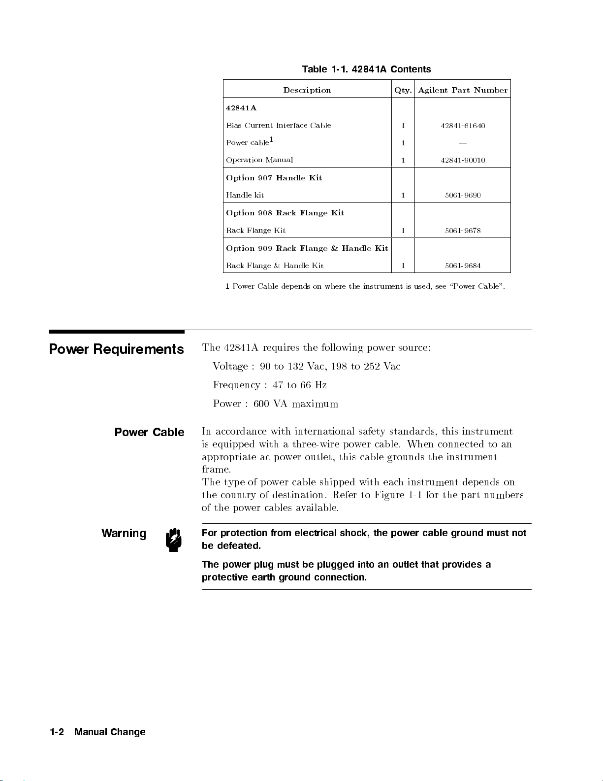
Table
1-1. 42841A
Contents
P
o
w
er Requirements
The
42841A
Bias
P
Op
Option
Handle
Option
Rac
Option
Rac
1
42841A
V
oltage
ow
er cable
eration
k
k
P
o
w
Curren
t
1
Man
907 Handle
kit
908
Flange
909
Flange
er
Cable
requires
:
90
Description Qt
Interface
Cable
ual
Kit
Rac
k
Flange
Kit
Kit
Rac
k
&
dep
to
Flange
Handle
ends
132
the
V
Kit
on
ac,
&
where
follo
198
Handle
the
instrumen
wing
to
252
Kit
p
o
w
Agilen
y
.
1 42841-61640
1 |
1 42841-90010
1 5061-9690
1 5061-9678
1 5061-9684
tis
used,
see
er
source:
V
ac
t
P
art
Num
b
er
\P
o
w
er
Cable".
P
W
arning
F
requency
P
o
w
er
In
o
w
er
Cable
accordance
is equipp
appropriate
:
:
600
with
ed with
ac
47
to
V
A
maxim
a
three-wire
p
o
w
er outlet,
66
Hz
um
in
ternational
safet
p
o
w
er
cable.
this cable
y
standards,
When
grounds the
this
instrumen
connected
instrument
to
t
an
frame.
The t
yp
e
of
p
o
w
er
cable
shipp
ed
with
eac
h
the
coun
of
the
For
protection
try
of destination.
p
o
w
er
cables
from
a
v
ailable.
electrical
Refer to
shock,
instrumen
Figure 1-1
the
po
w
er
cable
for the
t
dep
ends
part
n
um
ground must
on
b
ers
not
be defeated.
The po
wer plug must
be plugged into an outlet that pro
vides a
protective earth ground connection.
1-2 Manual Change
Page 29
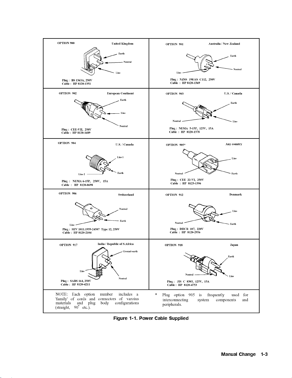
Figure 1-1. Power Cable Supplied
Manual Change 1-3
Page 30
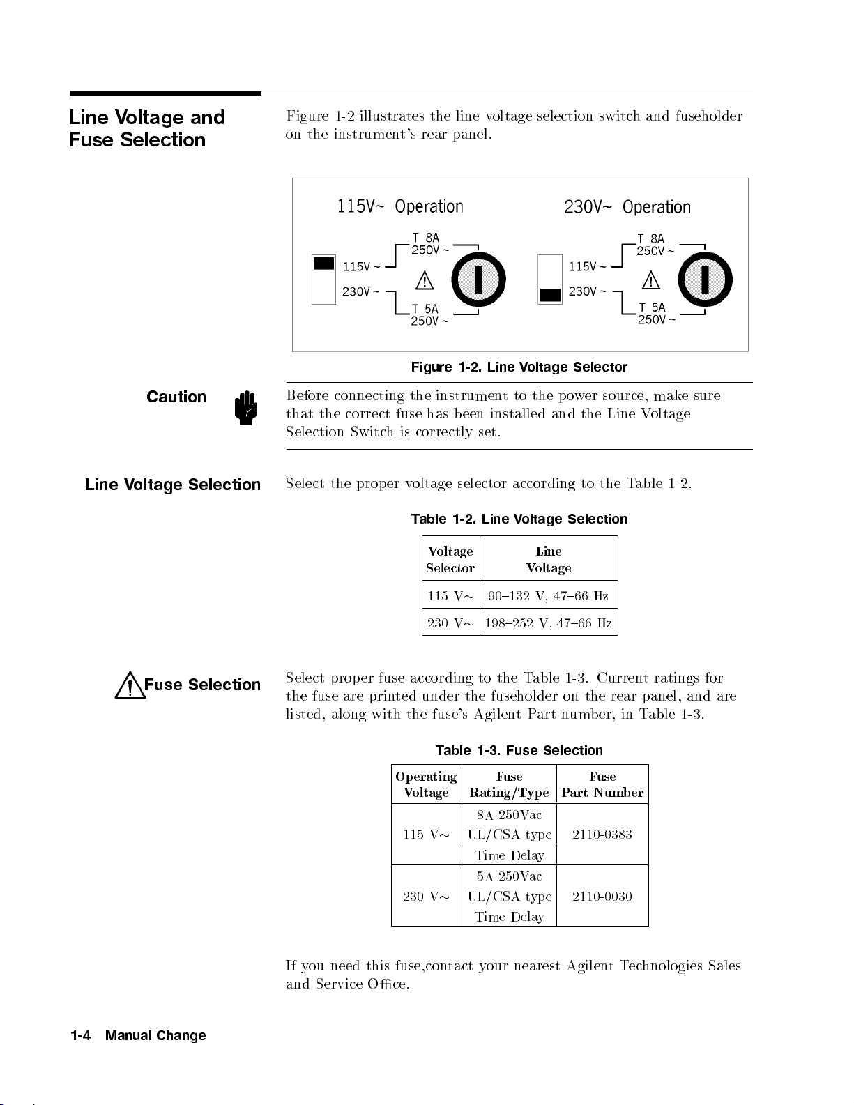
Line
Fuse
V
oltage and
Selection
Figure
on
1-2
the instrumen
illustrates
t's rear
the
line
panel.
v
oltage
selection
switch
and fuseholder
Line
Caution
V
oltage
Fuse
Selection
Selection
Before
that
connecting
the
correct
Selection Switc
Select
Select
the
listed,
the
prop
fuse are
along
prop
er
printed
with
fuse
his
er
fuse
Figure
the
instrumen
has
correctly
v
oltage
T
able
1-2.
V
oltage
Selector
115
V
230
V
according
under the
the
fuse's
T
able
1-2.
Line
b
een
installed and
set.
selector
Line
90{132
198{252
to
fuseholder
Agilen
1-3.
V
oltage
t
to
the
according to
V
oltage
Line
V
oltage
V,
V,
the
T
able
tP
art n
Fuse
Selection
Selector
p
o
w
er
the
Selection
47{66
47{66
1-3.
on
the
umb
source,
Line
the T
Hz
Hz
Current
rear
er, in
mak
V
oltage
able
1-2
ratings for
panel,
T
able
e
.
and
1-3
sure
are
.
1-4 Manual Change
Operating
Voltage
Fuse
Rating/Typ
8A 250V
115 VUL/CSA t
Time Dela
5A 250V
e
ac
ype
y
ac
Fuse
Part
Number
2110-0383
230 VUL/CSA type 2110-0030
Time Delay
If you need this fuse,contact your nearest AgilentTechnologies Sales
and Service Oce.
Page 31
Caution
Operation
Environment
Note
To
remov
ethe
fuse
p
ops
out.
Use
the
prop
the required
DO
NOT
use
to
b
y-pass
The
42841A
en
vironmen
42841A
T
emp
Humidit
The
to
erature:
y:
42841A
could cause
fuse, turn
er
fuse
for
current
a
a
blo
m
t
conditions, and
a
v
oid
m
rating and
mended
wn fuse.
ust
b
e
op
obstructing
C
to
0
less
than
ust
b
e
protected
condensation
the fuse
the
line v
fuse
Find out
erated
C
55
95%
within
holder
oltage selected.
of the
or
short-circuit
what caused
under
within
sucient
the
air
o
RH
at
40
from
temp
the
instrumen
coun
sp
ecied
space m
w
of
the
C
erature
terclo
Use only
t
yp
the
fuse-holder
the fuse
the
follo
ust
co
t.
c
kwise
e
as
replacemen
to
wing
b
e
k
ept
oling
fans.
extremes
un
til
the
fuses with
in order
blo
w!
b
ehind
the
whic
h
ts.
Electromagnetic
Compatibility
V
entilation
Requirements
This
pro
duct
has
the
Electromagnetic
T
o
use a
prop
erly
those
recommended
T
est)
to
connect
p
eripherals,
requiremen
T
o
ensure
equipmen
ts.
adequate
clearance around
b
een
designed
Compatibilit
shielded
in
the
eac
h
of
ts
v
en
tilation, mak
the
42841A.
cable
General
the
or
devices
ports
and
tested
y
(EMC)
or
shielded
Information
to their
ma
y
e sure
to
Directiv
coaxial
resp
ensure
that there
the
requiremen
e
and
ectiv
e
to
meet
ts of
89/336/EEC.
cable
(suc
h
the
P
erformance
con
trollers,
the
is adequate
as
Manual Change 1-5
Page 32
Instruction
for
Cleaning
Rack/Handle
Installation
T
o
prev
en
the
receptacle b
dipped
42841A
The
a
in w
in
analyzer can
measuremen
42841A.
t
electrical
efore cleaning.
ater
ternally
t
system.
to
.
be
sho
clean
rack
T
able
c
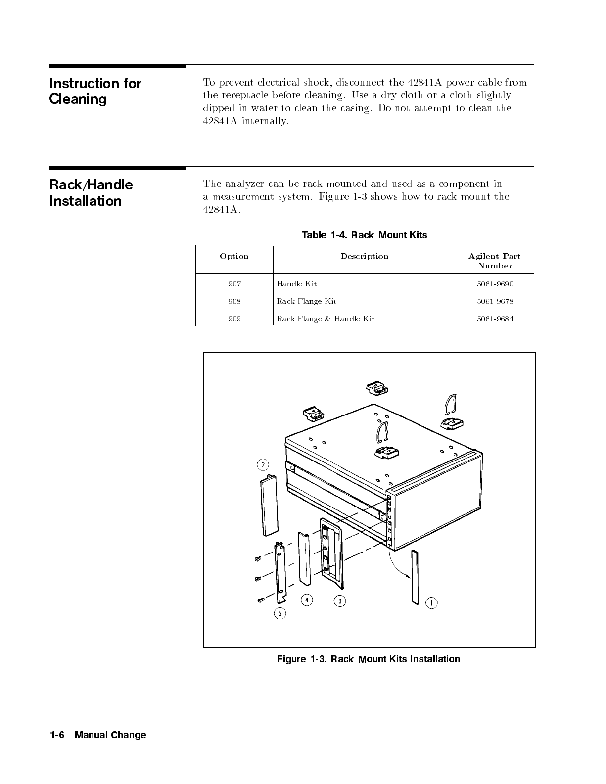
Figure
k, disconnect
Use a
the
casing.
moun
ted
and
1-3
sho
1-4.
Rack
the 42841A
dry cloth
Do
not
used
ws
ho
Mount
Kits
or a
attempt
as
a
comp
w
to
rac
po
wer
cable from
cloth sligh
to
clean
onen
k
moun
tly
the
t
in
t
the
Option Description Agilen
Num
907 Handle
908 Rack
909 Rac
k
Kit
Flange Kit
Flange
&
Handle
Kit
5061-9690
5061-9678
5061-9684
t
P
art
b
er
1-6 Manual Change
Figure 1-3. Rack Mount Kits Installation
Page 33
Option
907
Handle
Kit
Option
907
necessary
is
a
handle
hardware
kit
to attac
con
taining
h them
a
pair
to the
of handles
instrument.
and the
Option 908
Option
909
Rack Flange
Kit
Rack
&
Flange
Handle
Kit
Installing
1.
Remov
front
2.
A
ttac
3.
Attac
Option
the
908 is
necessary
equipmen
Mounting
1.
Remo
fron
t
2.
A
ttac
the
42841A using
3.
Remo
slide
Option
909
necessary
handles
spacing.
the
ethe
sides
h
the
hthe
t
rac
the
v
e
the
sides
h
the
v
e
all
the
hardw
attac
Handle
adhesive-bac
of
the
fron
t handles
trim
arac
k
hardw
k
with
Rack
adhesiv
of the
rac
k
moun
four
fo
ot
to
w
is
a
rac
k
are
hed,
in
42841A.
strips
3
ange
are
to
482.6
e-bac
42841A.
t
ange
the screws
feet
5
ard
the
moun
tkit
to
moun
an
equipmen
ked
trim strips
(Refer
2
to the
to
the
kit
con
moun
mm (19
k
ed
trim
(Refer
pro
(lift
bar
bar.)
con
t
them
handles.
taining
t
them
4
vided.
on
taining
t
rac
inches)
to
Figure
sides using
a
to
the
strips
to
Figure
to
the
the
inner
a
to
an
instrumen
k
with
1
from
1-3
.)
the
pair
of
instrumen
horizontal
1
from
1-3
.)
left
and righ
side
pair
of
482.6
the
left
screws
anges
spacing.
the
left
t fron
of
the
anges
t
whic
mm
(19
t
and
and
in
and
fo
and
h
inc
pro
an
t sides
ot,
has
hes)
righ
vided.
righ
of
and
the
t
t
Mounting
1. Remo
fron
t
sides
2.
A
ttac
h
on the
pro
vided.
3. Remo
slide the foot
the
Handle
ve
the adhesiv
of
the
fron
left and
the
t
righ
and
Rack
e-bac
42841A.
handle
t
fron
3
k
t
ed
and
trim
sides
the
of
strips
rac
k
the
1
from
moun
42841A
the
t ange
using
ve all four feet (lift bar on the inner side of the
toward the bar).
Manual Change 1-7
left
and
5 together
the
screws
foot, and
righ
t
Page 34

Page 35
2
Product Ov
Introduction
Product
Introduction
erview
This
c
hapter
op
erating
relation
and
The
an
Option
Option
including
front
The
bias
paralleled
the
42842B
Curren
b
et
eac
h
name
42841A
002
the
panel
42841A
from
t
Cable.
the Agilen
w
002
0.01A
to
Connections"
con
tains
een
the
of
the
is
a
bias
Bias
Accessory
DC
curren
k
eys.
using
with
to
20A
supply
Bias
Curren
F
or
in
Chapter
the
tMo
del 42841A
4284A
42841A
curren
Curren
Con
t
4284A
in three
the
maxim
t
system
information
/4285A
t
t
In
trol
bias
Precision
's
parts
source for
terface)
In
terface).
can
b
(20Hz
ranges.
um
of
T
est
Fixture
conguration,
3.
y
ou
will
Bias Curren
and their
use
with
or
with
So all
e
set
using
-
1MHz)
Tw
o
40A
DC
and
b
y
refer
need
to kno
t
Source,
LCR
meter
function.
the
4284A
the
4285A
measurement
the
4284A
co
v
ers
DC
42841As
curren
t
the
42843A
to
\
wb
suc
and
(with
(with
/4285A
curren
can
b
e
bias
combining
Bias
Instrumen
efore
h
as
the
42841A
an
setups
t
t
,
The
42841A
the
42842C
is used
is
co
v
ered.
The
4284A
oers
an
characteristics),
The
4284A
can
test
with the
when
additional
's
some
also
b
e
used
xture
42841A
for
,
used with
error
ov
er
frequency
measuremen
with
biased
the
DC
the 42841A
of
1%
(supplemen
range
t
the
measuremen
curren
functions
measurement range and Option 001 P
option. F
or details, refer to \Op eration Limitations" in Chapter 3.
4285A(75kHz
ts.
t
bias
range
, 42842A/B,
tal
p
from
1kHz
are
limited
-30MHz)
When
of
the
0.01A
and 42843A
erformance
to
1MHz.
such
42841A
as
ower Amplier/ DC Bias
to
and
10A
Product Overview 2-1
Page 36
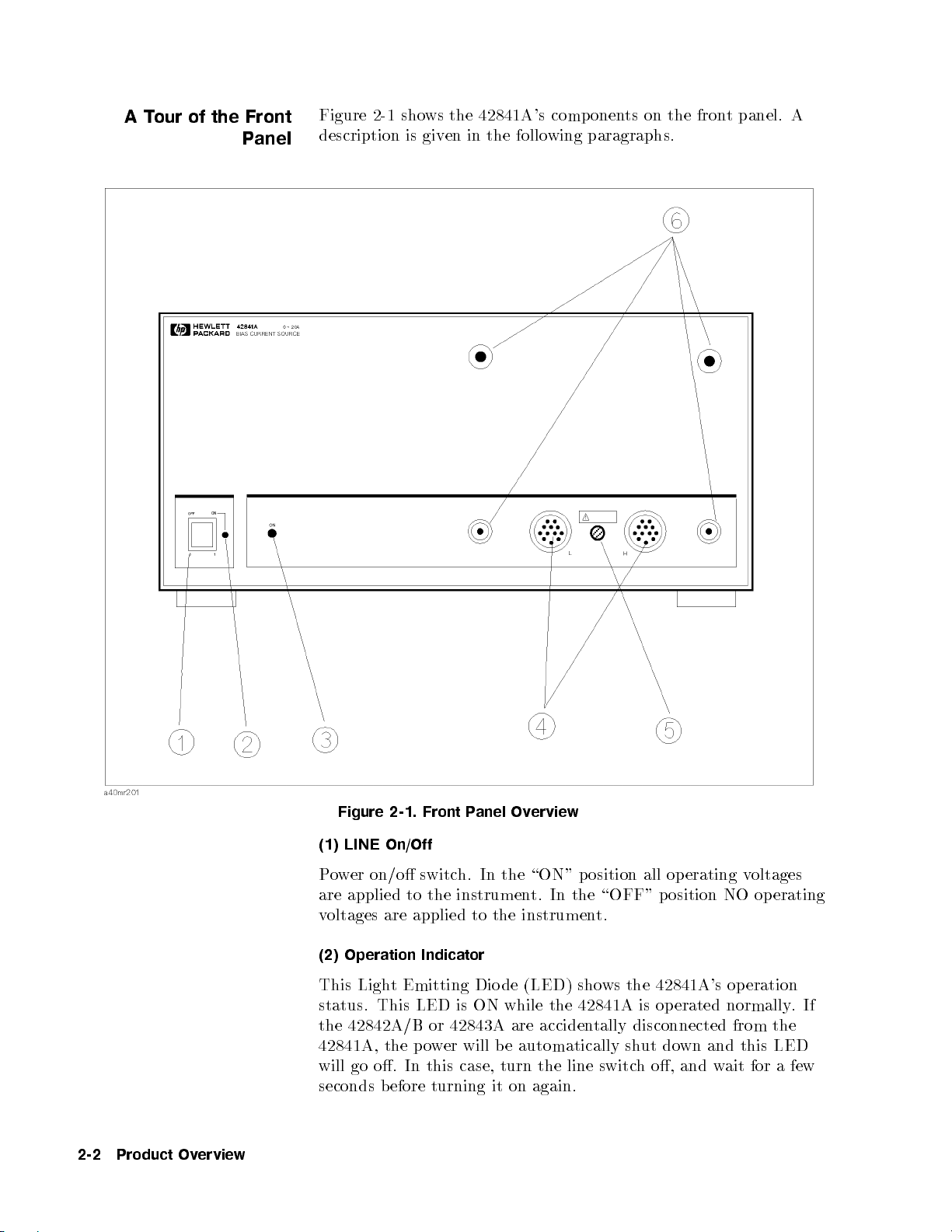
A
T
our
of
the
Front
P
anel
Figure
2-1
description
sho
is giv
ws
the
en in
42841A
the follo
's
comp
onen
ts
wing paragraphs.
on the
front
panel. A
2-2 Product Overview
Figure 2-1.
Front
P
anel
Ov
erview
(1) LINE On/Off
Power on/o switc
are applied to the instrumen
voltages are applied to the instrumen
(2) Operation
This Ligh
t Emitting Dio de (LED) sho
h. In
Indicator
the \ON" position all operating v
t. In
the \OFF" position NO operating
t.
ws the 42841A
's operation
oltages
status. This LED is ON while the 42841A is op erated normally.If
the 42842A/B or 42843A are accidentally disconnected from the
42841A, the power will b e automatically shut down and this LED
will go o. In this case, turn the line switch o, and wait for a few
seconds before turning it on again.
Page 37
(3) DC
This
LED
Bias Indicator
LED sho
is
lit,
DC curren
(4)
DC
Bias
ws the
DC
t bias
Current
curren
is not
Output
42841A's
t
bias
is
applied.
DC curren
applied.
t
bias
When
status.
this
When
LED is
this
OFF, the
These
connection,
of
(5)
This switc
is
safet
(6)
These
connectors
detects o
the
xture
Fixture Connection
hsenses
asserted,
y
Fixture
.
parts
the
Guide
are
co
v
er.
42841A
Holes
used
output
the
ver
temperature
Detector
connection
will
and
to
moun
DC
bias
of
42842A/B
sh
ut
do
wn
Threaded
t
the
42842A/B
curren
of
the
b
y
Studs
t,
detects the
xture,
or
42843A.
itself
in
for
the
fron
and
c
If
operator's
t
of
the
xture
hec
ks
this
42841A
status
switc
h
.
Product Overview 2-3
Page 38
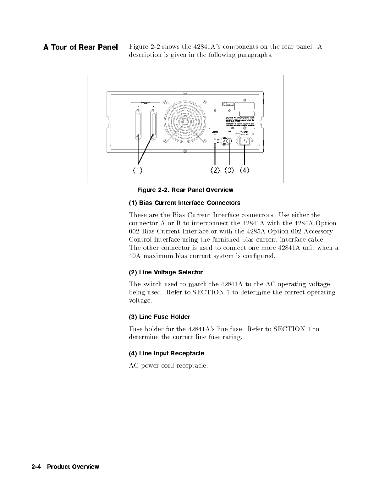
A
T
our
of
Rear
P
anel
Figure
2-2
description
sho
is giv
ws
the
en in
42841A
the follo
's
comp
onen
ts
wing paragraphs.
on the
rear panel.
A
Figure
(1)
Bias
These
connector
002
Con
The
40A
(2)
Line
The
being
v
oltage.
(3)
Line
F
use
determine
(4)
Line Input Receptacle
ACpo
2-2.
Rear
are
Bias
trol
other
maxim
switc
used.
holder
Current
Curren
In
V
oltage
h
Fuse
Interface
the
Bias
A
or
B
t
terface
connector
um bias
Selector
used
Refer
Holder
for
the
the
correct
wer cord receptacle.
P
anel
Curren
to
in
terconnect
Interface
using
is
curren
to
matc
to
SECTION
42841A's
line
Ov
erview
Connectors
t
In
terface
or
with
the
furnished
used
to
t
system
h
the
42841A
line fuse.
fuse
the
the
connect
is
1
to
rating.
connectors.
42841A
with
4285A
bias
curren
one
more
congured.
to
the
A
determine
Refer to
Use
either
the
Option
002
t
in
terface cable.
42841A
C
op
erating v
the
correct
SECTION 1
4284A
Accessory
unit
op
the
Option
when
oltage
erating
to
a
2-4 Product Overview
Page 39
3
Operation Procedure
Introduction
Operation
Limitations
4284A
Systems
This
When
based
This
20Hz
congurations
system
and
c
Op
eration
Basic
Examples
hapter
measurement
Measuremen
Practical
Remote
measuremen
con
using the
on
use.
system
-
conguration
1MHz)
and
theother
discusses
limitations
t
hin
ts
trol
function
42841A
Eac
h
conguration
with
the
for
t
w
o
is
the
follo
wing
procedures
t
examples
,
the
measuremen
uses
42841A
bias
curren
a
40A
bias curren
has the
the
and
t
topics:
4284A
the
ranges.
t
conguration
following
(measuremen
42842A/B.
One
is
t
system.
is
limitations.
t
frequency:
There
a
20A
are
bias
selected
t
w
o
curren
t
20A
System
The
follo
wing
4284A
42841A
42842A
16048A
In
terface
equipmen
Precision
LCR
Bias Curren
Bias
Curren
T
est
Lead
Cable(furnished
t
is
Meter
t Source
t
T
est
Fixture :
with
necessary
(with
Option
42841A
for
the basic
20A system.
002)
) :
:
1
:1
1
:
1
1
40A System
The follo
4284A
42841A Bias Curren
42842B Bias Curren
wing equipmen
t is necessary for the basic 40A
Precision LCR Meter (with Option 002)
t Source
tT
est Fixture
system.
:1
:2
:1
42843A Bias Current Cable :1
16048A Test Lead :1
Interface Cable(furnished with 42841A) :2
Operation Procedure and Examples 3-1
Page 40
Operation Limitations
Some
4284A functions
and
the
42842A/B.
hav
These
e limitations
limitations
when used
are:
with
the
42841A
4285A
System
Standard sp
Option
mo
de
001,
and
oscillator lev
disabled.
Measuremen
Open
compensation
The
cable
F
or
eac
h
of
Op
er
ation
Manual,
Me
asur
ement
This
system
30MHz) with
system.
The
following
system.
4285A
42841A
Precision
Bias
42842C Bias
(Order
16048A
In
terface
the
T
Option
est
Cable
ot bias
P
o
w
DC
curren
el is
t
range
length
the
ab
Setup
uses
the
the
42841A
equipment
LCR
Curren
Curren
Lead
(furnished
(1.5V or
er
Amplier/DC-bias,
t
limited to
is
can not
setting
o
v
e
men
Se
ction
2V) is
Isolation
2V
limited
b
applies
tioned
3,
Display
rms
to
e
.
4285A(measuremen
and
42842C.
is
necessary
Meter
t
Source
t
T
est
Fixture
001,
SMD
T
est
with
42841A
disabled.
are
turned
,and
10
and 100
used
when
for
the
functions,
Format
t
This
for
Fixture.)
)
is
disabled.
OFF. The
the
6
40V DC-bias
the
1
m
setting
refer
,and
frequency:
is
10A
a
basic
So
High
maximum
ranges only
42841A
is
only
to
the
4284A
Se
ction
75kHz
bias
curren
4285A
bias
.
:
:
:
:
:
P
is
.
used.
4,
-
t
curren
1
1
1
1
1
o
w
er
t
Operation
Some
4285A
42842C.
Option
Cable length setting
Refer to the
details.
3-2 Operation Procedure and Examples
Limitations
These
001, In
functions
limitations
ha
ternal DC
v
e
limitations
are:
Bias is
disabled.
applies for the 1 m setting only
4285A Precision LCR Meter Op
when
used with
eration Manual
42841A and
.
for
Page 41
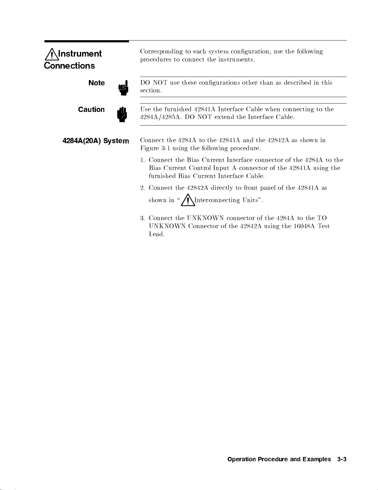
Instrument
Connections
Corresp
pro
cedures to
onding
to
eac
h
system
connect the
conguration,
instruments.
use
the follo
wing
Note
Caution
4284A(20A)
System
DO NOT
use these
section.
Use
the
furnished
4284A/4285A.
Connect
Figure
1.
the
3-1 using
Connect
Bias
Curren
the
furnished
2. Connect
sho
3.
Connect
UNKNO
wn in
the 42842A
\
the
WN
Lead.
DO
4284A
the follo
Bias
t
Con
Bias
Curren
UNKNO
Connector
congurations other
42841A
NOT
to
In
In
extend
the
wing pro
Curren
trol
Input
t
directly
terface
42841A
t
In
In
terface
Cable
the
and
cedure.
terface
A
connector
Cable.
to
fron
terconnecting Units".
WN
connector
of
the
42842A
than as
In
terface
the
connector
t
panel
of
the 4284A
using
when
Cable.
42842A
of
the
of
described
connecting
as
shown
of
the
4284A
42841A using
the
42841A
to the
the
16048A
in this
to
the
in
to
as
TO
T
est
the
the
Operation Procedure and Examples 3-3
Page 42
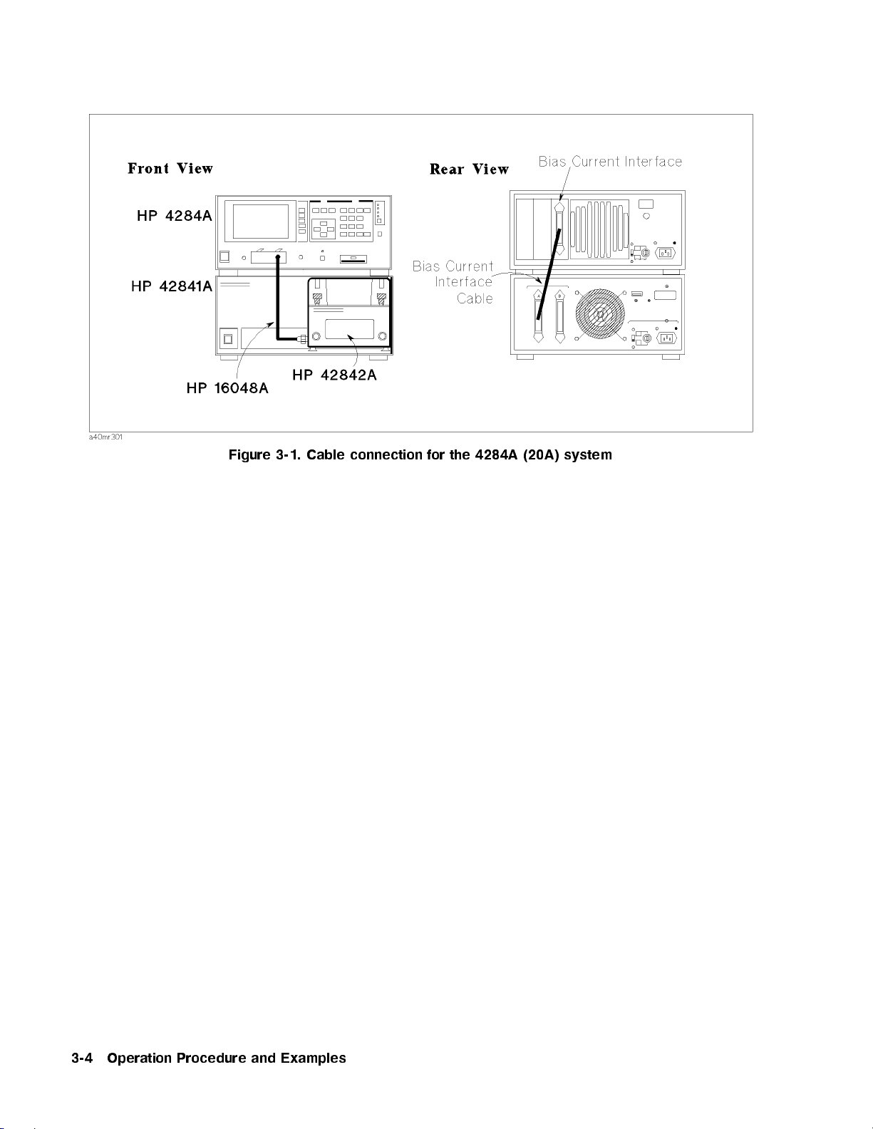
Figure
3-1.
Cable
connection
for
the
4284A
(20A)
system
3-4 Operation Procedure and Examples
Page 43
4284A(40A)
System
Connect
Figure
the
4284A
3-2 using
to
the
the follo
42841A
wing pro
and
cedure.
the
42842A
as
shown
in
Caution
1. Connect
Curren
Bias
Current
2.
Connect
connected
Input
A Connector
Curren
3.
Connect
sho
wn
4.
Connect the
UNKNO
5.
Connect
whic
h
is
Input
Connector
Curren
When
turn
In
20A,
Curren
in
o a
terface
y
ou
t
the
Cable.
In
the 4284A
t
Input
the
42841A
to
t
In
terface
the
42842B
in
\
4284A
WN
the
DC
not
connected
t Cable.
40A
single
m
ust
completely
terface
Bias Curren
A
Connector
Interface
Cable(1).
Bias
the
4284A
of the
Cable(2).
directly to
In
terconnecting
UNKNO
Connector
Bias
Curren
of
the
conguration
42841A
When
Cable,
y
or
ou
and
t
of
the
Curren
in
step
1to
other
Units".
WN
of
42842B
t
Output
with
the
42842B
side
sho
DO
NOT
c
hange
disconnect
the
42843A
In
terface
42841A
t
Con
the Bias
42841A
front
Connector
using
Connector
using the
trol
Input
using
panel of
the
Current
the
the 42841A
to
16048A
Connector
42842B
wn
and DC
panel
using
in
Figure
disconnect
3-2
the
the conguration
one
of
the
42841As
Bias
Curren
to
furnished
B
Connector
Control
furnished
the
TO
T
est
of
the
Bias Curren
an
42843A
DO
NOT
Bias
Curren
from
,
its
t
Cable.
the
Bias
Bias
as
Leads.
42841A
Bias
40A
to
Bias
t
t
Operation Procedure and Examples 3-5
Page 44
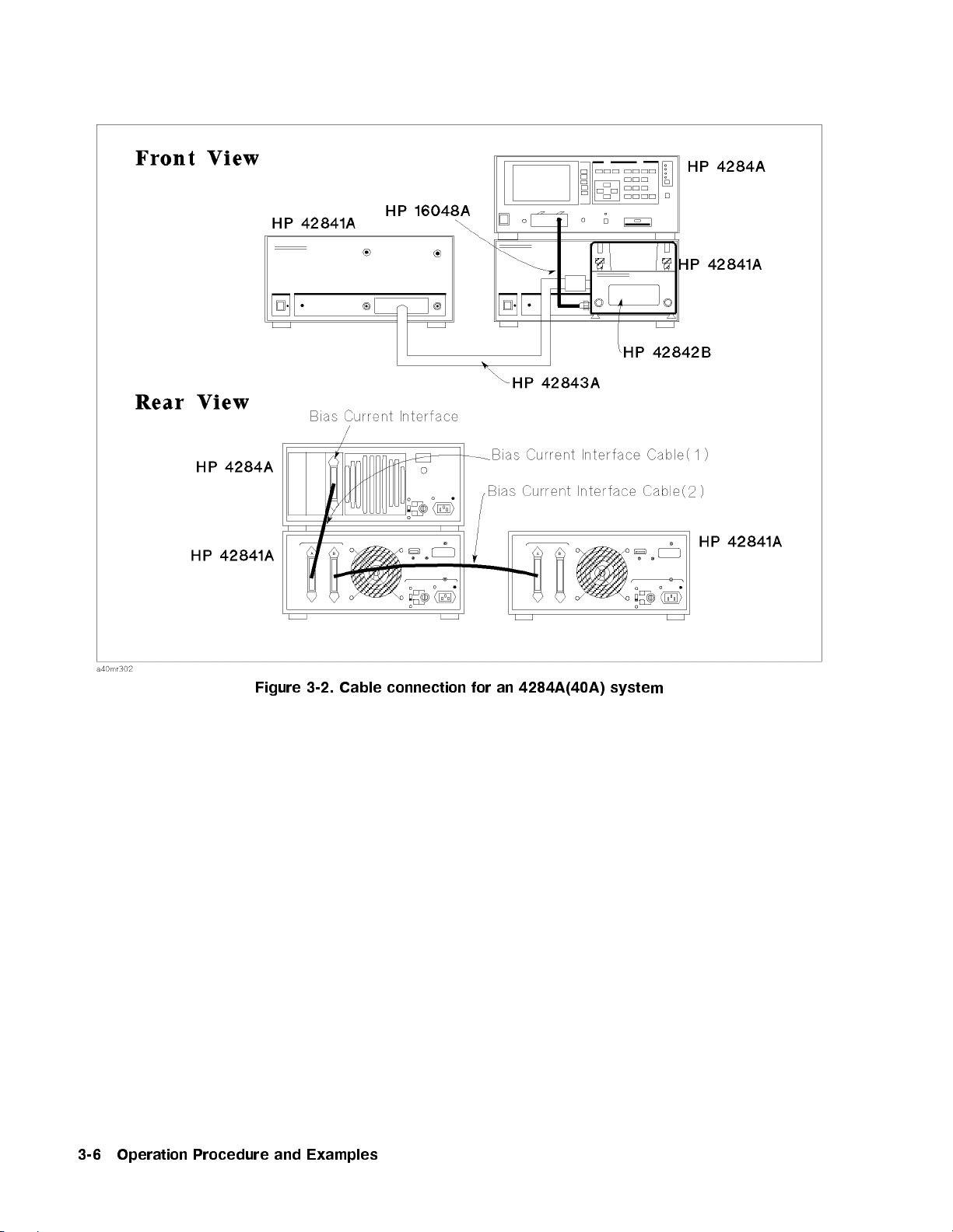
Figure
3-2.
Cable
connection for
an 4284A(40A)
system
3-6 Operation Procedure and Examples
Page 45
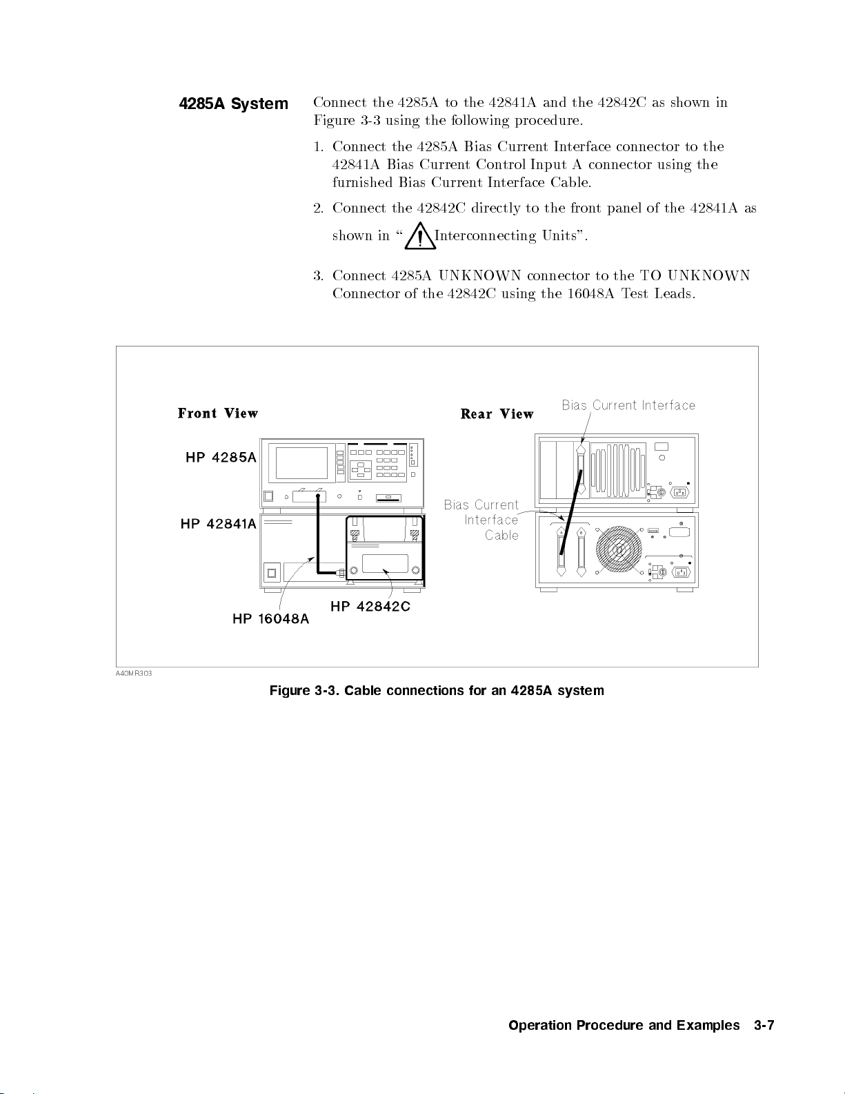
4285A
System
Connect
Figure
the
4285A
3-3 using
to
the
the follo
42841A
wing pro
and
cedure.
the
42842C
as
shown
in
1. Connect
42841A
furnished
2.
Connect
sho
wn in
3.
Connect
Connector
the 4285A
Bias
Curren
Bias Curren
the
42842C
\
In
4285A
UNKNO
of the
Bias Curren
t
Con
tIn
directly
t
In
terface
trol
Input
A
terface Cable.
to
the
fron
terconnecting Units".
WN
connector
42842C using
the
16048A
connector
connector using
t
panel
of
the
to the
TO UNKNO
T
est
Leads.
to
the
the
42841A
as
WN
Figure 3-3.
Cable connections
for an
4285A
system
Operation Procedure and Examples 3-7
Page 46
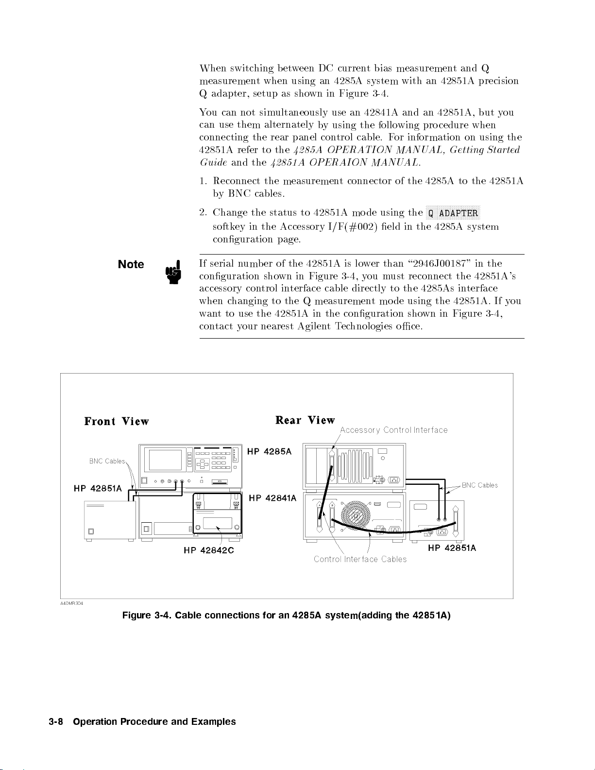
Note
When switc
measuremen
Q
adapter,
You
can not
can
use them
connecting
42851A refer
Guide
1.
2.
and
the
Reconnect
by
BNC cables.
Change
softk
ey
the
in
conguration
If
serial
num
conguration
accessory
when
w
an
con
tact
c
hanging
t
to
control
use
y
our
hing b
setup
t
when
etw
een DC
using
as sho
simultaneously
alternately
the
rear
panel
to the
4285A OPERA
42851A
the
measuremen
status
the
to 42851A
Accessory
page.
ber
of
the
sho
wn
in
interface
to
the
Q
the
42851A
nearest
Agilen
current
an
4285A
wn in
Figure 3-4
use an
b
y
using
con
trol
OPERAION
t
connector
mode
I/F(#002)
42851A
Figure
cable
is
lo
3-4
,
directly
measurement
in
the
conguration
t
T
ec
hnologies
bias
measuremen
system
with
.
42841A and
the
follo
cable.
F
an 42851A,
wing
pro
or
information on
TION MANUAL,
MANUAL
.
of
the 4285A
using the
eld
in
the
w
er
than
\2946J00187"
y
ou
m
ust
reconnect
to
the
4285As
mode
using the
sho
wn
oce.
an
42851A
cedure
N
N
N
N
N
N
N
NN
NN
Q
ADAPTER
4285A
in
t
and
precision
but
when
using the
Getting
to the
NN
NN
N
N
N
N
N
N
N
N
N
N
N
N
N
N
system
in
the
42851A's
in
terface
42851A.
Figure 3-4
Q
y
Starte
42851A
the
If
,
ou
y
d
ou
Figure 3-4. Cable connections for an 4285A system(adding the 42851A)
3-8 Operation Procedure and Examples
Page 47
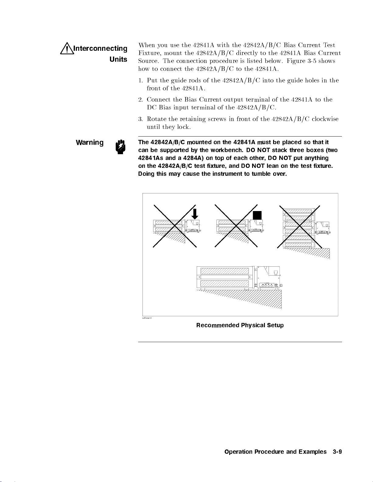
Interconnecting
Units
W
arning
When
Fixture,
Source. The
ho
1.
2.
3.
The
can
42841As
on
Doing
y
ou
use
mount
connection pro
w
to
connect
Put the
front
Connect
DC
Rotate
un
guide ro
of
the
the
Bias input
the
til
they
retaining
lo
42842A/B/C mounted
be
supported
and
a
the 42842A/B/C
this
ma
y
the
42841A
with
the 42842A/B/C
cedure is
the
42842A/B/C
ds of
the 42842A/B/C
42841A
Bias
.
Curren
t
terminal of
screws
ck.
on the
b
y
the
w
orkbench.
4284A)
on
top
test fixture,
cause
the
instrument
the
42842A/B/C
directly to
listed
b
to
the
42841A.
into
output terminal
the
42842A/B/C.
in
fron
t
of
the
42841A must
DO
NOT
of
each
other, DO
and
DO
NOT
to
tumble
Bias
the 42841A
elo
w.
Figure
the guide
of the
42841A to
42842A/B/C
be
placed
stack
three
NOT put
lean
on
the
o
v
er.
Current
Bias Curren
3-5
sho
holes
in
clo
c
so
that
bo
xes
anything
test
fixture.
Test
ws
the
the
kwise
it
(tw
t
o
Recommended
Operation Procedure and Examples 3-9
Physical
Setup
Page 48
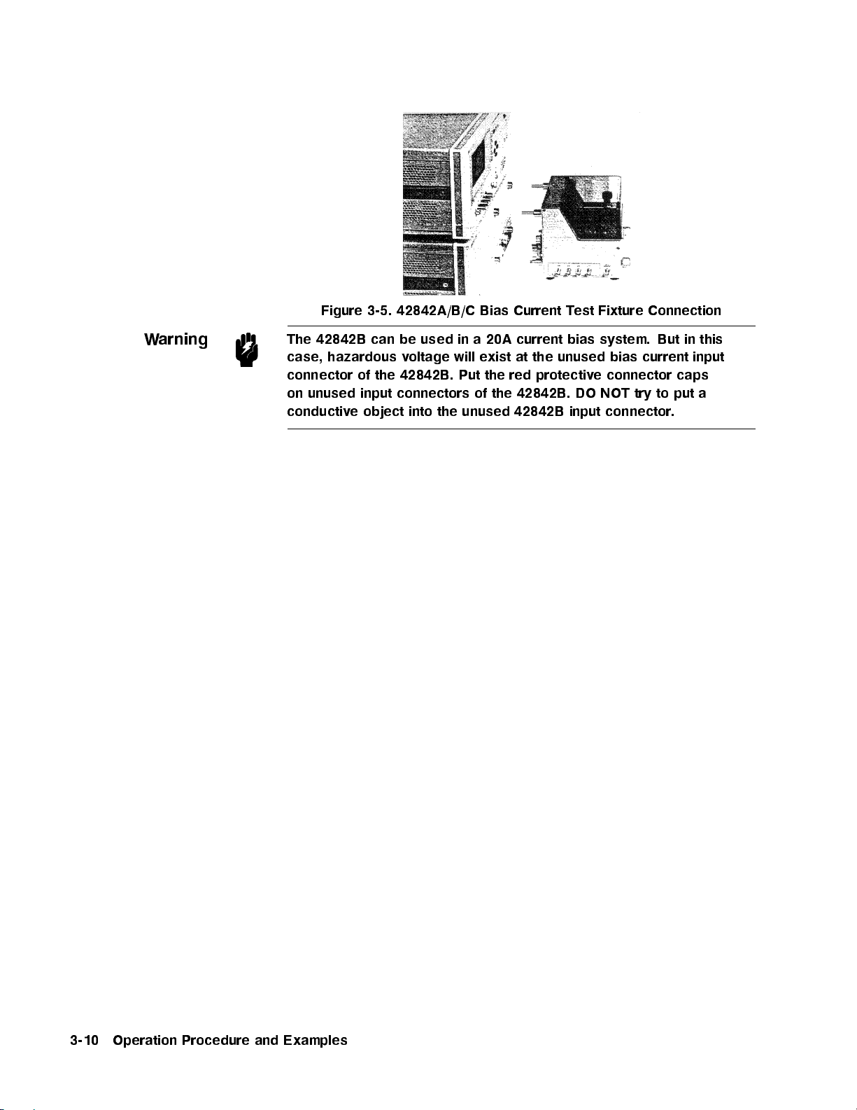
W
arning
Figure
The
42842B
case,
hazardous
connector
on
unused
conductiv
3-5. 42842A/B/C
can
be
used
v
oltage will
of
the
42842B.
input
connectors
e
object
into
the
Bias Current
in
a
20A
exist at
Put
the
of
the
unused
current
the unused
red
protectiv
42842B.
42842B
Test
bias
DO
input
Fixture
system.
bias
e
connector
NOT
try
connector.
Connection
But
in this
current
input
caps
to
put
a
3-10 Operation Procedure and Examples
Page 49
Basic
Measurement
Procedure
The
measuremen
the
same as
for standard
conditions can
be
t
pro
set
cedure
using
for
applying
4284A/4285A op
the
fron
t
panel
a
high curren
eration. All
k
eys
of
the
tDC
bias is
measurement
4284A/4285A.
Note
Measurement
Procedure
When
bias
the 4284A
of
0.01A
to
is
20A
com
(40A)
bined
MEASUREMENT DISPLA
page.
Option
(#002)
F
or
details
Manual,
42841A
4284A
's
Op
Message
For
details
Manual,
The
42841A
disconnection
42842A/B/C or
A
t
ypical
follo
ws.
1.
Mak
e
When
eld
on
Section
error
er
ation
.
on
Getting
high
sure
using
002
installation
on
the
CONFIGURA
the
4284A's
6, Me
messages
Manual,
the
4285A's
Starte
will
automatically
of
the
42842A/B/C
the
42843A
DC
curren
that
Option
the
4285A,
asur
when
d
Guide
t
step.
with
can
b
e
Y
page
can
b
TION
operation,
ement
Pr
com
App
endix B,
op
eration,
.
sh
ut
or
to
the
biased
002
set
measuremen
is
installed
to
the
the
(t
set on
or the
e
monitored
refer to
o
c
e
dur
bined
Error
refer
do
wn the
the
42841A
I
BIAS
w
o)
the
42841A
BIAS
(s),
a
eld on
current
the
MEASUREMENT SETUP
on
the
I
BIAS
I/F
page.
the
e
A
nd
with
an
Message A
to
the
output when
42843A.
b
efore
t
pro
at
the
conguration
4284A
Examples
4284A,
4285A
Connect
turning
system
cedure
Oper
.
F
refer
nd
System
Op
er
it detects
the
it
is
cong
at
ation
or
to
ation
on.
as
page.
this
the
Note
2.
Set
up the
3.
P
erform
When
m
ust
using
ha
4. Connect
v
e
error
the
already
the
measurement
4285A,
device
terminals.
5. Press the
6. P
erform the measuremen
7. Press the
4
DC BIAS
4
DC BIAS
conditions.
correction.
CABLE
b
een
accomplished.
under
5
key,
CORRECTION
test
(DUT)
to enable the DC bias output.
t.
5
key, to disable the DC bias
to
for
the
measuremen
output.
a
1
m
cable
t
Operation Procedure and Examples 3-11
Page 50
Confirm the
Mak
e sure
A
CCESSOR
installed in
4
CAT
ALOG/SYSTEM
the
4285A,
NN
NN
pressing
Set
I BIAS
Up the
System Condition
that I
NN
NN
BIAS I/F(#002)
Y
I/F(#002)
SYSTEM/CONFIG page
5
and
it
m
ust
N
N
N
N
Measurement Conditions
set
N
N
N
N
N
N
N
N
.
in
case
NN
NN
NN
NN
N
N
N
N
N
N
N
N
N
N
N
NN
NN
DC
NN
Curren
SYSTEM CONFIG
to
of
NN
NN
NN
NN
in case
the
4285A,
which
N
N
N
N
N
N
N
N
is
t
Bias
of
the
4284A,
is
already
is displa
pressed.
Measuremen
In
yed
a
when the
case
of
t
Mo
de
b
y
Note
Note
First, set
function,
in
tegration
4284A/4285A's fron
Op
er
or
the
Close
setting
P
erforming Error
Cable
set
with
to
an
When
ha
v
the
4
CA
T
remain after
up the
test
frequency
time.
ation
Manual,
4285A
the
up
Length
CABLE
an
42842A/B
using
e
already
CABLE
ALOG/SYSTEM
Op
42842A/B/C
the
Correction.
LENGTH
4284A.
the
b
CORRECTION
the
measurement
These
er
measuremen
Correction
Use
or
4285A, the
een
5
and
p
o
,
test
signal
measuremen
t panel
Se
ation
the
4285A
accomplished.
w
er
keys.
ction
6,
Me
Manual,
Bias
Curren
t conditions.
As
describ
correction
16048A
and
1
m
N
N
N
N
N
N
is
page
N
N
NN
NN
N
N
N
N
N
N
turned
N
N
N
CABLE CORREC
conditions suc
lev
el,
DC
t
parameters
F
or
details,
asur
ement
Getting
to
test leads
the
CABLE
DO
whic
N
N
N
N
N
N
N
N
N
N
N
o
Starte
t
T
est
ed
in
1
m
when
42842C.
CORRECTION
the
h
is
N
N
N
NN
N
. This
once
Fixture
\Op
to
1
the
h
as
measuremen
curren
can
refer
Pr
o
c
e
dur
dGuide
co
eration
the
in
terconnect
m cable
displa
y
ed
correction
correction
t
bias,
and
b
e set
to
the
4284A
e
And
Examples
.
ver,
b
efore
Limitations",
42841A
correction at
b
y
data
is
is
the
m
ust
pressing
executed.
t
from
,
used
4284A
will
Y
ou
m
Note
execute the
DUT's
or the DUT's imp edance is
extend the measuremen
Extension".
Open Correction.
correction is not applied while the 42841As are used with an 4284A.
Turn
must p erform an OPEN correction. When you use extension leads,
physically arrange the extension leads as they will be for the actual
measurement and perform an OPEN correction.
3-12 Operation Procedure and Examples
ust
the OPEN correction OFF. In the case of an 4285A, y
extend
OPEN/SHOR
leads
are
the
measuremen
T
to
o
short
to
t connector, refer to \Measuremen
As described in \Operation Limitations", OPEN
t
connector
correction
connect
less than 50
the
using
in
follo
wing
measurement
H. F
or details on ho
leads
cases;
b
efore
When
connector,
wto
tT
erminals
ou
y
ou
a
Page 51
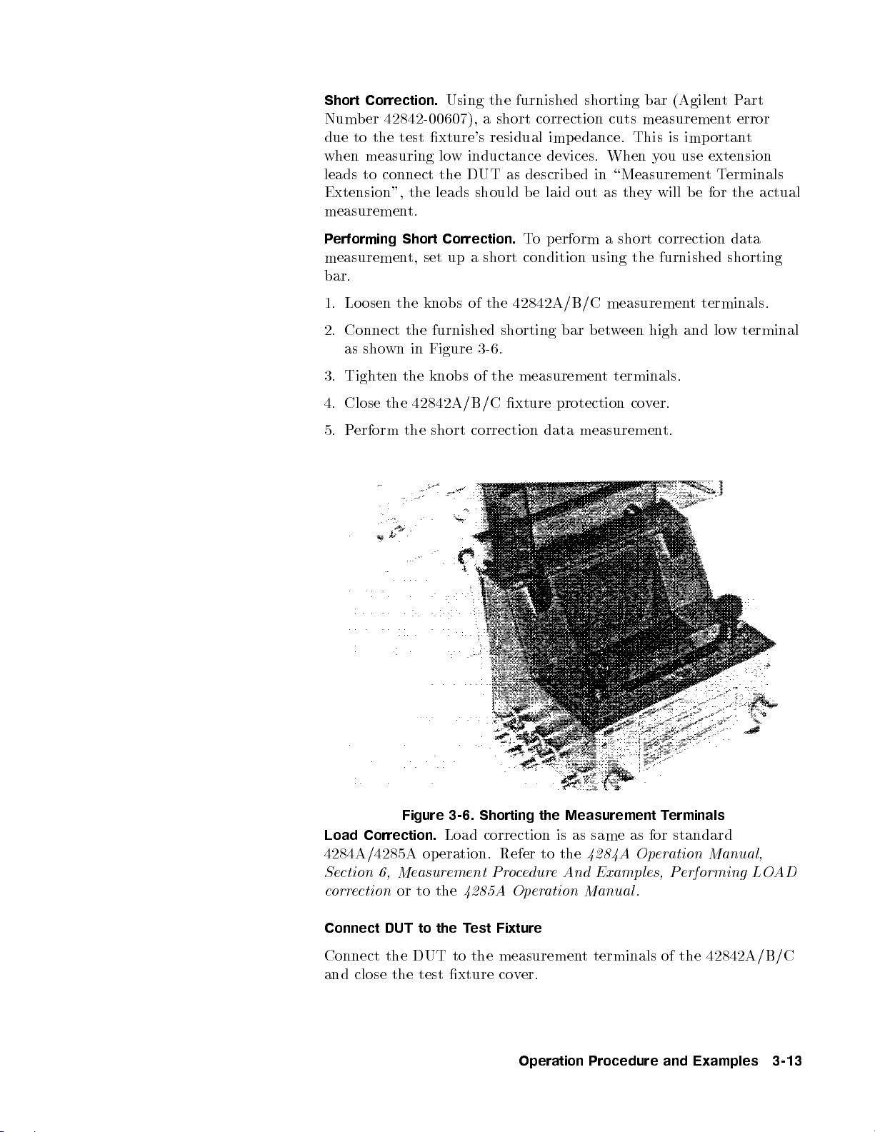
Short Correction.
Num
b
er
42842-00607),
due
to
the
test xture's
when measuring
leads
to
connect
Extension",
measuremen
P
erforming
measuremen
the leads
t.
Short
t,
set
bar.
1.
Lo
osen
the
knobs
2.
Connect
as sho
3.
Tigh
4.
Close
5.
P
erform
the
wn in
ten
the
the
42842A/B/C
the
Using the
low
inductance
the
DUT
should b
Correction.
up
a
of
furnished
Figure
knobs
short
of
correction
furnished shorting
a
short
correction
residual imp
devices.
as
described
e laid
T
o
p
short
condition
the
42842A/B/C
shorting
3-6
.
the
measuremen
xture
data
cuts
edance. This
When
in \Measuremen
out as
erform
a
using the
measuremen
bar
b
etw
t
terminals.
protection
measuremen
bar (Agilen
measuremen
is imp
y
ou
use
they will
short
b
correction
furnished shorting
een high
co
and lo
v
er.
t.
tP
t
ortant
extension
tT
erminals
e
for
the
data
t
terminals.
w
art
error
actual
terminal
Figure 3-6. Shorting the Measurement T
Load Correction.
Load correction is as same
4284A/4285A operation. Refer to the
Section 6, Me
c
orrection
asurement Pr
or to the
ocedur
4285A Op
eA
eration Manual
4284A Op
nd Examples, Performing LO
erminals
as for standard
eration Manual,
AD
.
Connect DUT to the Test Fixture
Connect the DUT to the measurement terminals of the 42842A/B/C
and close the test xture cover.
Operation Procedure and Examples 3-13
Page 52
Note
Note
Caution
Warning
The
42842A/B/C is
to
prev
en
t
the
eects of
measure a
sligh
connection
If
the
t
dierence
DUT's
device whic
in
the
direction.
leads
can't
42842A/B/C, extend
to
\Measuremen
DO
NOT
42842A/B/C
damaged b
The
device
due
to
high
place
DUT
yheat
under
pow
t
T
the
from
test,
er
dissipation
device.
carefully designed
magnetic p
hhas
an op
en magnetic
measured
reac
imp
h
the measuremen
the measuremen
erminals
DUT
b
o
x.
Extension"
to
o
close
The
side
the
DUT.
terminals
of
panel of
and
the
using alumin
ermeability
edance
v
t terminals
describ
to
the
side
the DUT
adjacent
DUT.
Be
um
.Ho
wev
path,
alue
dep
t terminals
as
ed
in
panel
area ma
careful
and
er, when
there
ma
ending
of the
necessary
next
section.
of
the
bo
x
will
y become
in
exchanging
plastic
you
y
b
e
on the
.
Refer
b
e
hot
a
the
W
arning
Enable the
T
urn
fron
t
and
the
Hazardous
input
red
protectiv
the
42842B.
DC
the
DC
bias
panel.
The
42841A
v
oltages
connectors
e
caps
DO
Bias
Output
on
DC
will
of
the 42842B
on
NOT
using
bias on/o
ligh
t
may
be
the
try
to
connector.
P
erforming
The
4284A/4285A susp
DC
bias
current
the
curren
settles
Measurement
ends measuremen
t
of
the
42841A
do
wn,
the
4284A/4285A
measurement. Measuremen
of the 4284A/4285A
according to the displa
5
k
the
4
DC
sim
ultaneously
present
BIAS
LED
ey
indicators
.
on
the
connected
unused
put
bias
a
conductiv
current
t automatically
is
in transition.
automatically
t results are displa
on
the
4284A/4285A's
of
the
4284A/4285A
unused
to
e
object
the
input
bias
current
42841A
.
connectors of
into
the
Put
42842B
while the
When the
con
DC bias
tin
ues
yed on the LCD displa
y page format selected.
the
the
y
3-14 Operation Procedure and Examples
Page 53
In the
turned
following
OFF
while
cases, the
the
measuremen
applied DC
t
bias curren
is
b
eing
t
p
erformed.
is
automatically
Fixture
DC bias
The
Bac
42842A/B/C
Fixture
cov
er is
open.
current
42842A/B/C
k-e.m.f. (electromotiv
is
defectiv
co
v
er
op
source
o
v
erheats.
en
detector
of
the
e force)
e.
42841A
is
protection circuit
wire
is op
en.
o
v
erloaded.
of the
Operation Procedure and Examples 3-15
Page 54
Caution
Note
DO
ma
If
y
the
NOT allo
damage
DUT
wthe
side
ov
erheated, in
automatically cuts
displa
ys
E-22
Fixture
displa
y.
In this
case, let
temperature
panel
of the
ternal temp
the DC
over
the 42842A/B/C
of
the
42842A/B/C.
bias
o.
Also
temperature
DUT
to
exceed
erature-responsiv
the
4284A/4285A
error
message
co
ol
do
wn
un
180
ereed
b
on
til
it
C
which
switch
eeps
the
reco
and
LCD
v
ers.
W
arning
Disable
When
through
with
o
v
the
the
the
the
4
DC
erheating
DC
measuremen
4284A/4285A
V
ery
high
v
oltages
circuit
The
Turn
42842A/B
is
opened
stored
the
bias
energy
Bias
DUT
BIAS
the
and
off
Bias
Output.
un
5
key
DUT.
the
(many
while
is
before
Current
t
is
nished,
til
y
ou
turn
on the
DC
4284A/4285A fron
bias
42841A
kilo
v
olts)
a
high DC
proportional
disconnecting
T
est
fixture.
DC
it
OFF.
on/o
will
LED
go
o
are
generated
bias current
to
the
the
bias
curren
Turn
indicators
sim
ultaneously
square
device
OFF the
t
panel
if
is flo
wing
of
the
under
t
is
an
still
o
DC bias
to
prev
of
the
.
inductiv
through
current
test
wing
e
flo
from
en
t
it.
wing.
the
3-16 Operation Procedure and Examples
Page 55
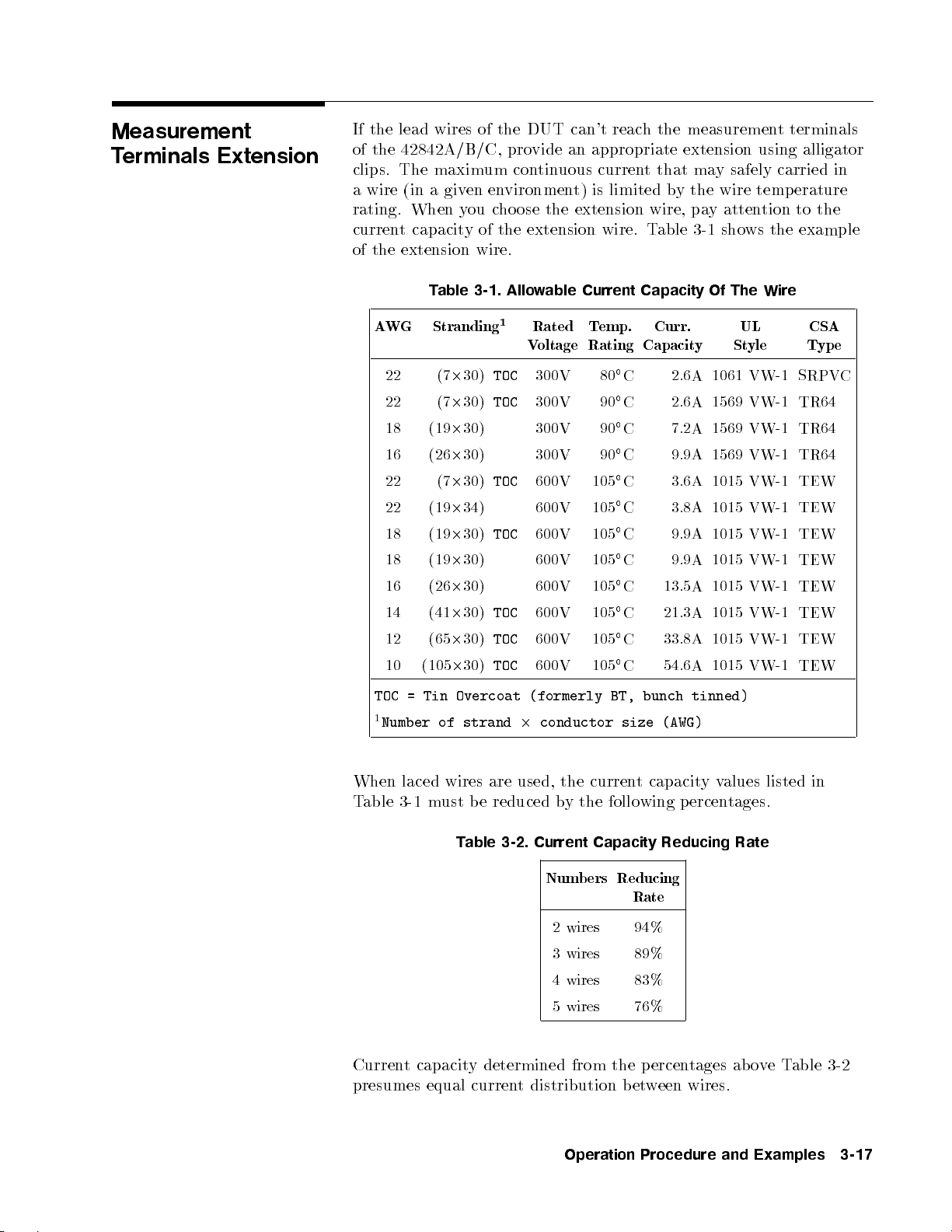
Measurement
T
erminals Extension
If
the
lead
wires
of
the 42842A/B/C,
clips. The
a
wire
rating.
curren
of
the
maximum
(in
a
giv
When y
t
capacit
extension
T
able
of
the
provide
con
en
environmen
ou c
hoose
y
of
the
wire.
3-1.
Allo
DUT
can't
an appropriate
tin
uous
t) is
the extension
extension
w
able
Current
reach
curren
limited b
wire.
Capacity
the measuremen
extension using
t
that
ma
y
safely
ythe
wire temp
wire, pa
T
able
3-1
y
sho
Of
atten
The
t terminals
carried
tion
ws
the
Wire
alligator
in
erature
to
the
example
A
WG
22 (7
22
18
16
22
22
18
18
16
14
12
10
TOC
=
1
Number
Stranding
2
30)
(7
2
30)
(19
2
30)
(26
2
30)
(7
2
30)
(19
2
34)
(19
2
30)
(19
2
30)
(26
2
30)
(41
2
30)
(65
2
30)
(105
2
30)
Tin
Overcoat
of
strand
1
Rated
V
oltage
TOC
300V
TOC
300V
300V
300V
TOC
600V
600V
TOC
600V
600V
600V
TOC
600V
TOC
600V
TOC
600V
(formerly
2
conductor size
T
emp.
Rating
80
90
90
90
105
105
105
105
105
105
105
105
BT,
Curr.
Capacit
C 2.6A
C
C
C
C
C
C
C
C
C
C
C
2.6A
7.2A
9.9A
3.6A
3.8A
9.9A
9.9A 1015
13.5A
21.3A
33.8A
54.6A
bunch
(AWG)
St
y
1061 VW-1
1569
1569
1569
1015
1015
1015
1015
1015
1015
1015
tinned)
UL
yle
VW-1
VW-1
VW-1
VW-1
VW-1
VW-1
VW-1
VW-1
VW-1
VW-1
VW-1
CSA
T
ype
SRPVC
TR64
TR64
TR64
TEW
TEW
TEW
TEW
TEW
TEW
TEW
TEW
When
T
able
laced
3-1
m
wires
ust
T
b
e
able
are
used,
reduced
3-2.
the
b
y
Current
curren
the
follo
Capacity
t
capacit
wing
p
ercen
y
Reducing Rate
v
alues listed
tages.
in
Numbers Reducing
Rate
2 wires
3 wires
4 wires
94%
89%
83%
5 wires 76%
Current capacity determined from the percentages ab oveTable 3-2
presumes equal current distribution between wires.
Operation Procedure and Examples 3-17
Page 56
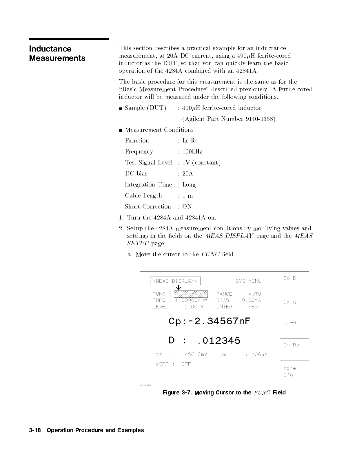
Inductance
Measurements
This
section
measuremen
inductor as
op
eration
The
basic
describ
t, at
the DUT,
of
the
pro
cedure
20A DC
4284A
\Basic Measuremen
inductor
will
b
e
measured
es
a
practical
current,
so
that
com
bined with
for
this
tPro
cedure" describ
under
example
using a
y
ou
can
quic
an 42841A
measuremen
the
follo
for
an inductance
490
H ferrite-cored
kly
learn
.
t
is
the same
ed previously
wing
conditions.
the
.
basic
as for
A
the
ferrite-cored
Sample
Measuremen
F
unction
Frequency
T
est
Signal
DC
bias
In
tegration
Cable
Short
Correction
1.
T
urn the
2.
Setup
settings
SETUP
a.
Mov
(DUT)
t
Conditions
Lev
Time :
Length
4284A
the 4284A
in
the
page.
e
the
cursor
:
490
(Agilent
:
Ls-Rs
:
100kHz
el
:
1V
:
20A
Long
:
1
m
:
ON
and
42841A
measuremen
elds
on
to
H
ferrite-cored
(constan
the
MEAS
the
FUNC
Part
Numb
t)
on.
t
conditions
eld.
inductor
er
DISPLA
9140-1358)
b
y
mo
difying
Y
page
v
alues
and the
and
MEAS
3-18 Operation Procedure and Examples
Figure 3-7. Moving Cursor to the
FUNC
Field
Page 57
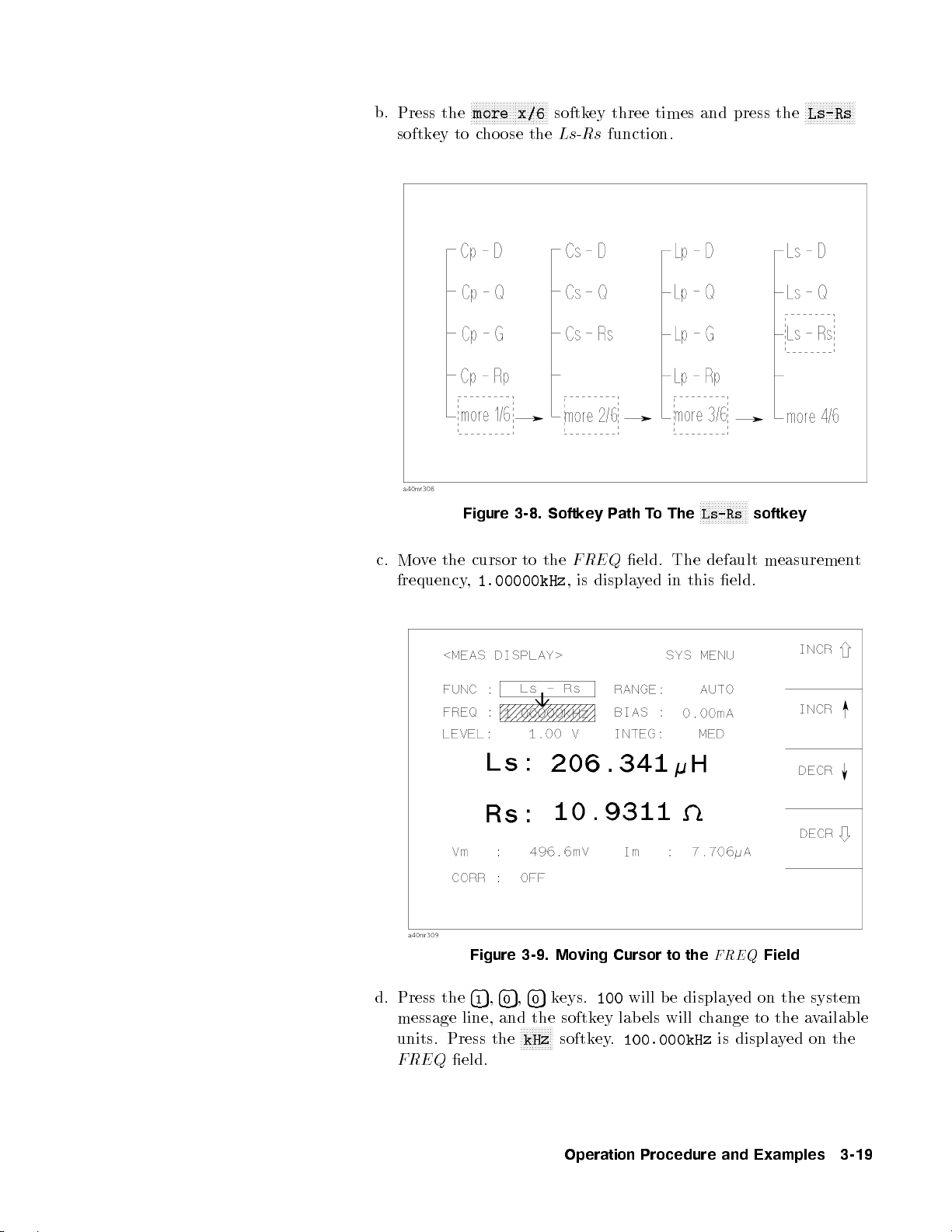
b.
Press
softk
ey
the
NN
NN
more
to
c
Figure
N
N
ho
NN
NN
N
N
N
N
N
N
N
N
N
N
N
N
N
N
N
N
N
NN
NN
NN
NN
N
x/6
softk
ey
three
times
and
press
the
ose
the
3-8.
Ls-Rs
Softk
function.
ey
P
ath
N
N
N
N
N
N
N
N
N
N
N
N
N
N
N
N
The
Ls-Rs
T
o
softk
ey
N
N
Ls-Rs
N
N
N
N
N
c.
Mo
v
e
the
cursor
frequency
,
Figure 3-9. Mo
d. Press the
415,405,405
message line, and the softkey lab els will change to the available
units. Press the
FREQ
eld.
to
the
1.00000kHz
keys.
NNNNNNNNNNN
kHz
FREQ
,
is
displa
eld.
y
ed
ving Cursor to the
100
will b e displayed on the system
softkey.
100.000kHz
The
in
default
this
FREQ
measuremen
eld.
Field
is displayed on the
t
Operation Procedure and Examples 3-19
Page 58
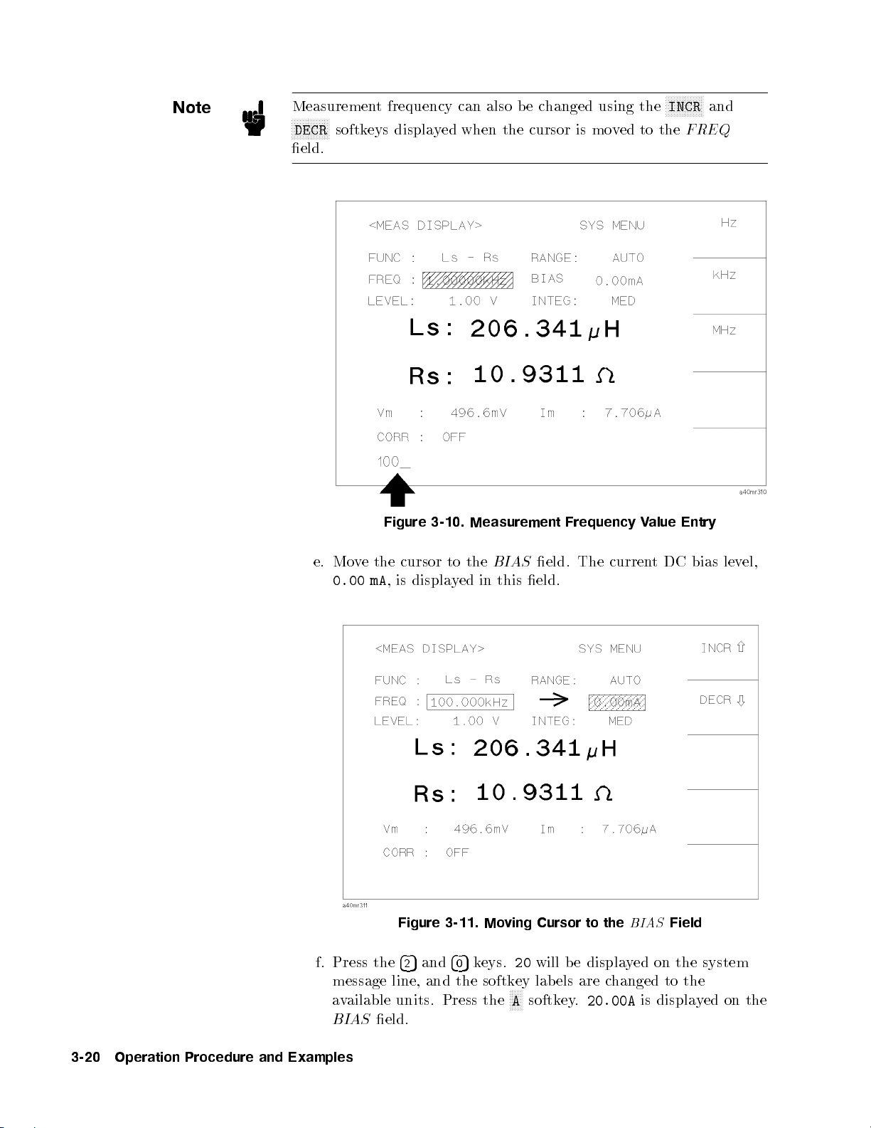
Note
Measuremen
NN
NN
NN
NN
NN
N
N
N
N
DECR
softk
eld.
t frequency
eys displa
y
ed
can also
when
the
be
cursor
c
hanged
is
using
mo
N
NN
NN
NN
NN
NN
N
N
N
INCR
the
v
ed
to
the
and
FREQ
e.
Mo
0.00
v
e
Figure
the
mA
,
cursor
is
displa
3-10.
Measurement
to
the
y
ed
in
BIAS
this
eld.
eld.
Figure 3-11. Moving Cursor to the
Frequency
The curren
V
alue
BIAS
t
DC
Field
Entry
bias
lev
el,
f. Press the
message line, and the softkey lab els are changed to the
available units. Press the
BIAS
3-20 Operation Procedure and Examples
eld.
425
and
405
keys.
20
will be displayed on the system
NNNNN
A
softkey.
20.00A
is displayed on the
Page 59
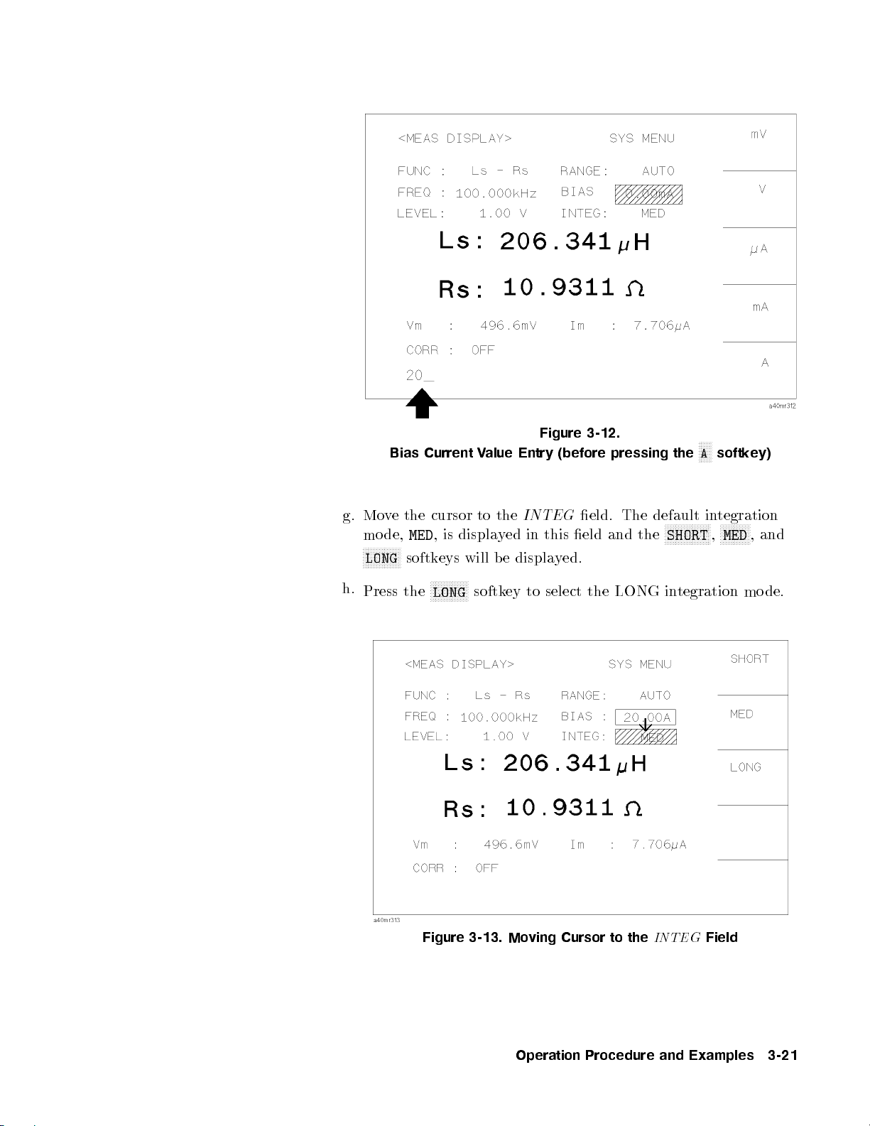
g.
h.
Mo
v
mo
de,
N
N
N
N
N
N
N
NN
LONG
Press
Bias
e
N
N
N
N
N
the
MED
softk
the
Current
cursor
,
is
displa
eys
N
NN
N
N
N
N
N
N
N
N
N
LONG
will
N
N
Value
to
b
softk
Figure
Entry (before
the
INTEG
y
ed
in
this
e
displa
ey
to
select
y
ed.
3-12.
eld.
eld
the
and
pressing the
The
default
N
N
N
N
N
N
N
SHORT
the
LONG
in
tegration
N
N
N
N
N
N
N
N
N
N
N
A
softk
in
tegration
N
N
N
N
N
N
NN
N
N
MED
,
N
N
N
N
mo
ey)
N
, and
de.
Figure 3-13. Moving Cursor to the
Operation Procedure and Examples 3-21
INTEG
Field
Page 60
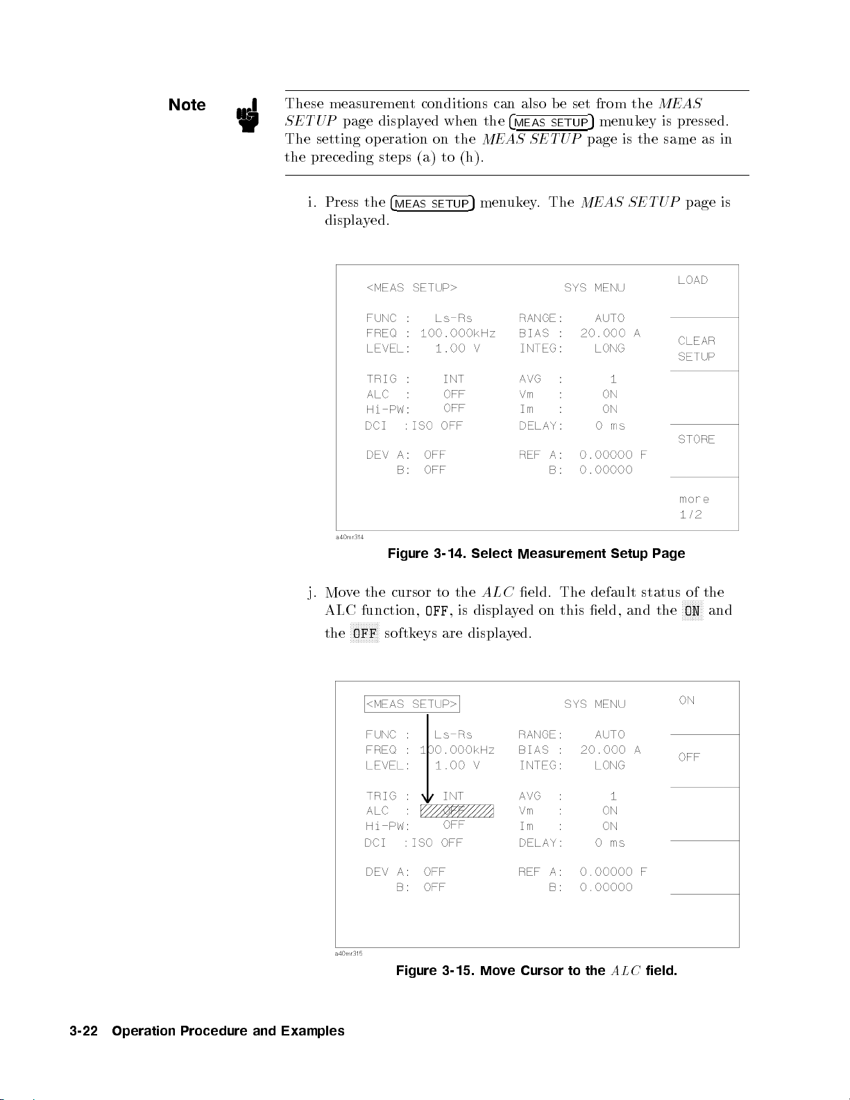
Note
These
SETUP
measurement
page
The setting
the
preceding
displa
y
operation
steps
conditions can
ed
when the
on the
(a)
MEAS SETUP
to
(h).
also b
4
MEAS
e
set
SETUP
from
5
men
page is
the
uk
ey
the
MEAS
is
pressed.
same
as
in
i.
j.
Press
displa
Mo
v
ALC
N
OFF
the
the
4
yed.
Figure
e
the
cursor
function,
N
N
N
N
N
N
N
N
N
N
softk
MEAS
OFF
eys
SETUP
3-14.
to
the
,
is
are
5
men
Select
ALC
displa
displa
uk
ey
.
The
Measurement
eld.
The default
y
ed
on
this
y
ed.
MEAS SETUP
Setup P
age
status
eld,
and
the
page is
of
the
N
N
NN
NN
N
N
ON
and
3-22 Operation Procedure and Examples
Figure 3-15. MoveCursortothe
ALC
field.
Page 61
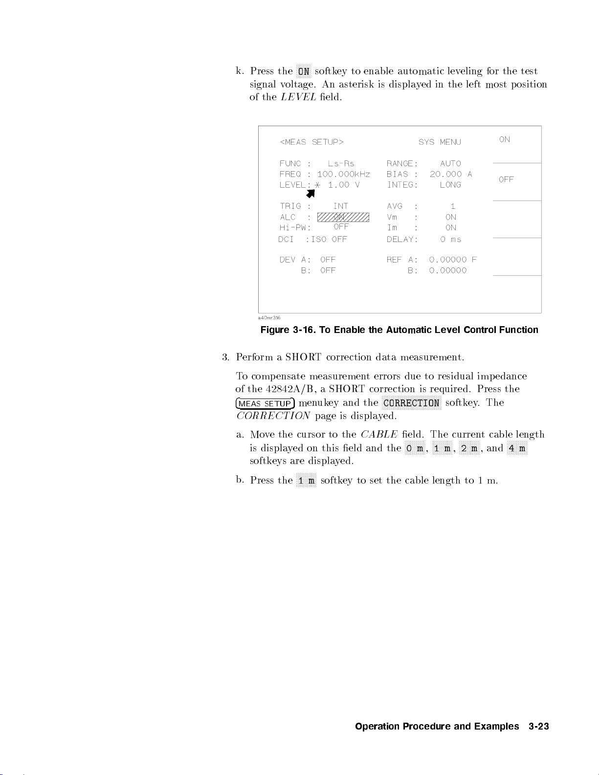
k.
Press
signal
of
the
NN
NN
ON
the
v
oltage.
LEVEL
N
N
N
N
softk
An
eld.
ey
to
asterisk
enable
is
automatic
displa
y
ed
lev
in
the left
eling
for
the
most p
test
osition
Figure
3. P
erform
T
o
comp
of
the
42842A/B,
4
MEAS
SETUP
CORRECTION
a.
Mo
v
e
is displa
softkeys
b.
Press
3-16.
a
SHOR
ensate
5
the
cursor
yed
are
N
the
T
o
Enable
T
correction
measuremen
a
SHOR
men
uk
ey
page
to
on
this
displa
y
N
N
N
N
N
N
N
N
N
N
1
m
softkey
and
is
the
eld
ed.
the
data
t
errors
T
correction is
the
displa
y
CABLE
and
to set
Automatic
measuremen
due
to
N
N
N
N
N
N
N
N
N
N
N
N
N
N
N
N
N
N
N
N
N
N
N
N
NN
CORRECTION
ed.
eld.
N
N
N
N
N
N
N
N
N
N
N
0m
the
,
the cable
Lev
el
t.
residual
required.
N
N
N
N
N
N
softk
The
curren
N
N
N
N
N
N
N
N
N
N
N
N
N
2m
1m
,
length
Control
imp
Press
ey
.
The
t
N
N
N
N
N
N
N
N
N
, and
to
1
m.
Function
edance
the
cable
N
4m
length
N
N
N
N
N
N
N
N
N
N
Operation Procedure and Examples 3-23
Page 62
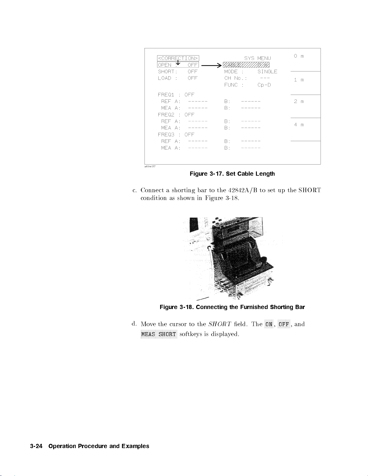
c.
Connect
condition
a
shorting
as
sho
Figure
wn
bar
in
3-17.
to
the
Figure
Set
Cable
42842A/B
3-18
.
Length
to
set
up
the
SHOR
T
d.
Mo
NNNNNNNN
MEAS SHORT
3-24 Operation Procedure and Examples
Figure
v
e
the cursor
NNNNNNNNNNNNNNNNNNNNNNNN
3-18.
Connecting
to
the
SHOR
softkeys is displa
the
T
yed.
eld.
Furnished
The
Shorting
N
N
N
NN
NN
N
ON
,
N
N
N
NN
OFF
Bar
NN
NN
NN
,
and
Page 63
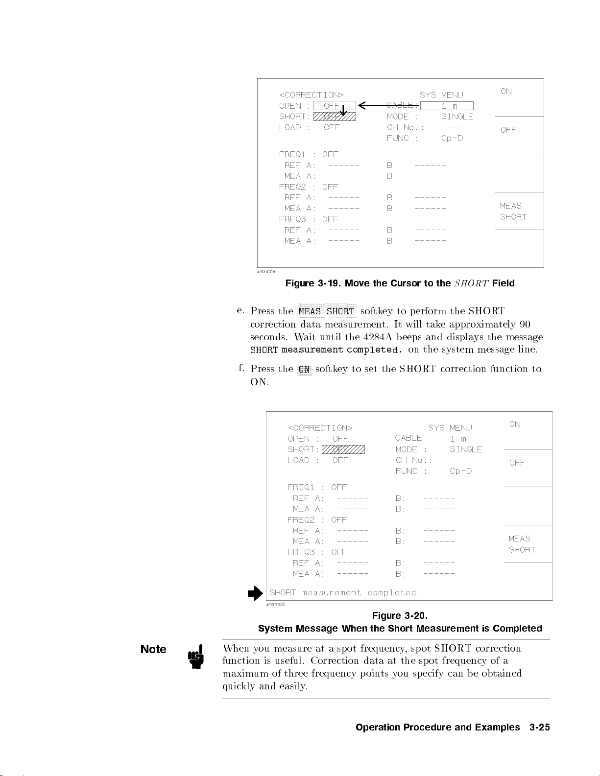
e.
Press
correction
seconds.
SHORT
f.
Press
ON.
Figure
the
N
NN
NN
MEAS
data
W
ait
3-19.
N
N
N
N
N
N
N
N
N
N
N
N
N
N
N
N
N
N
SHORT
measuremen
un
til
N
NN
Mo
NN
NN
the
v
ethe
N
N
softk
4284A
ey
t.
measurement completed.
N
N
N
N
NN
N
N
ON
softk
the
ey
to
set
the
Cursor
to
p
It
will
b
eeps
on the
SHOR
to
the
erform
tak
and
T
SHOR
the
SHOR
e
appro
ximately
displa
ys
system
message
correction
T
Field
T
the
function
90
message
line.
to
Note
Figure 3-20.
System Message When the Short Measurement is Completed
When you measure at a sp ot frequency,spotSHORT correction
function is useful. Correction data at the spot frequency of a
maximum of three frequency p oints you specify can be obtained
quickly and easily.
Operation Procedure and Examples 3-25
Page 64
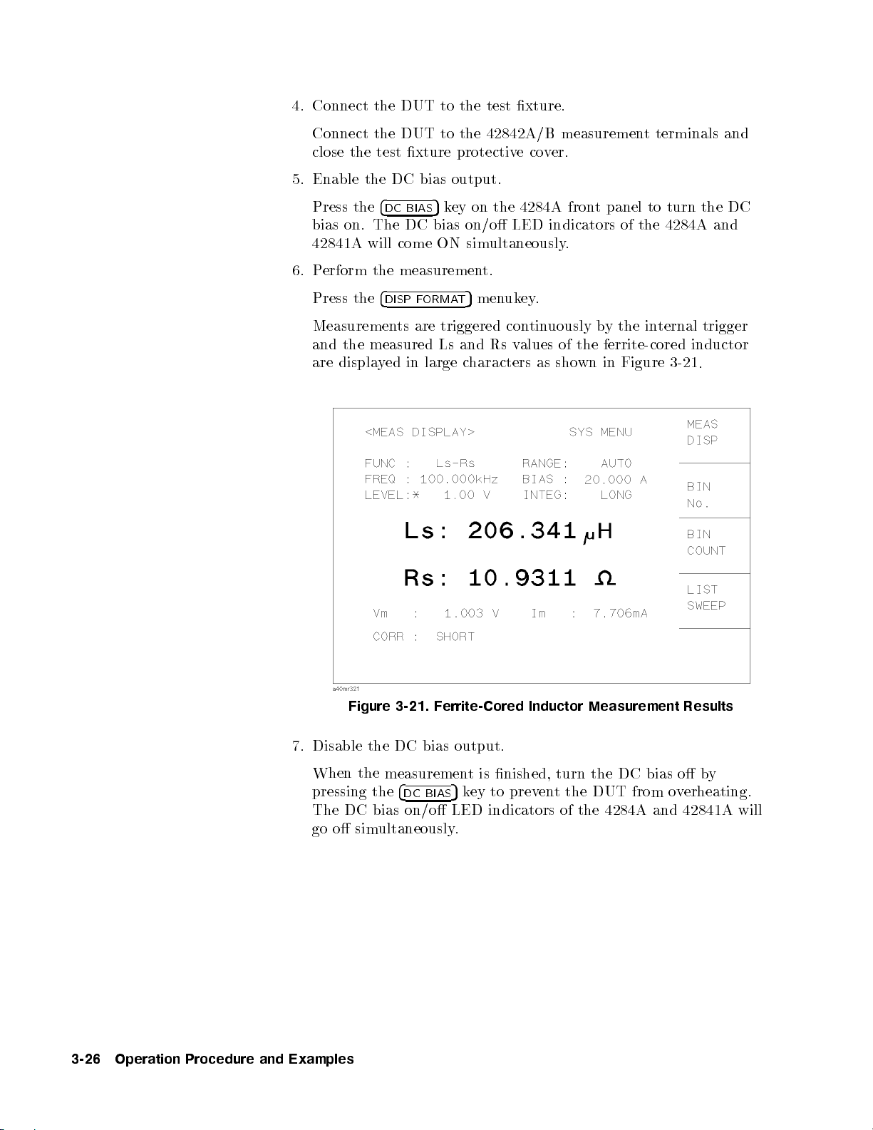
4.
Connect
the
DUT
to
the
test
xture.
Connect
close the
5.
Enable the
Press the
bias
on.
42841A
6.
P
erform
Press
Measuremen
and
the
are
displa
the
test xture
DC bias
4
DC BIAS
The
will come
the
the
4
DISP
measured
y
ed
DUT
to
the
protective
output.
5
k
ey
DC
bias
on/o
ON sim
measuremen
ORMA
triggered
Ls
large
5
T
and Rs
c
haracters
ts
F
are
in
42842A/B
on
the
4284A
LED indicators
ultaneously
t.
men
uk
ey
con
values
measuremen
cov
er.
fron
.
.
tin
uously
of the
as
sho
t
panel
of the
b
y
the
ferrite-cored
wn
in
Figure
t
terminals
to
turn
4284A and
in
ternal
3-21
and
the
DC
trigger
inductor
.
7.
Disable the
When
pressing the
The DC
go o sim
3-26 Operation Procedure and Examples
Figure
3-21.
DC
the
measuremen
4
Ferrite-Cored
bias
DC BIAS
output.
t
is
nished,
5
key to prev
Inductor
Measurement
turn
the
DC
ent the DUT from o
bias
Results
o
b
v
erheating.
bias on/o LED indicators of the 4284A and 42841A will
ultaneously.
y
Page 65
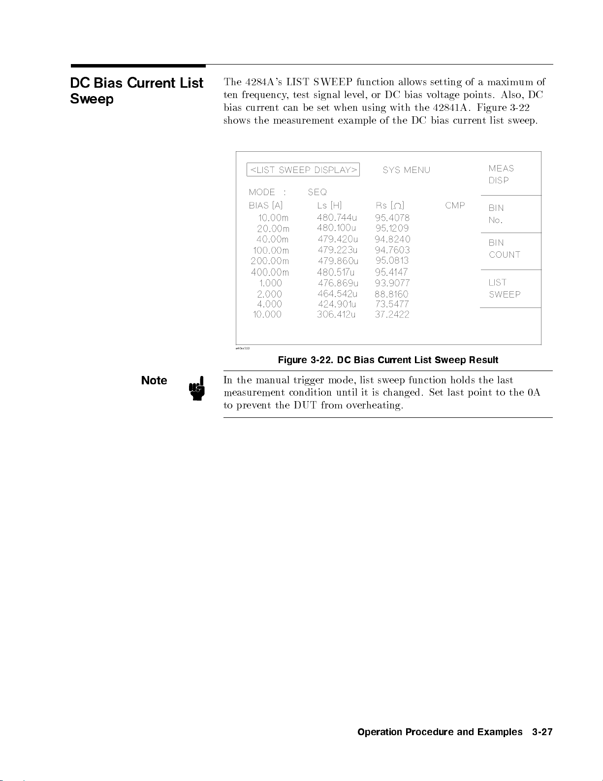
DC
Sw
Bias
eep
Current List
The
4284A's
ten
frequency,
bias curren
sho
ws
the
LIST
SWEEP
test signal
tcan
b
e
set
measuremen
level,
when
t
example
function
or DC
using
of the
allo
with
ws
bias v
the
DC bias
setting
oltage p
42841A
current
of a
oin
.
Figure
maximum
ts.
Also,
3-22
list sw
of
DC
eep.
Note
In
the
man
measuremen
to
prev
en
t
Figure 3-22.
ual
trigger
t
condition
the
DUT
mo
from
DC
de, list
un
til
o
v
Bias
Current
sw
it is
c
hanged.
erheating.
eep
List
Sw
function
Set
eep
holds
last
Result
the
p
oin
last
t
to
the
0A
Operation Procedure and Examples 3-27
Page 66
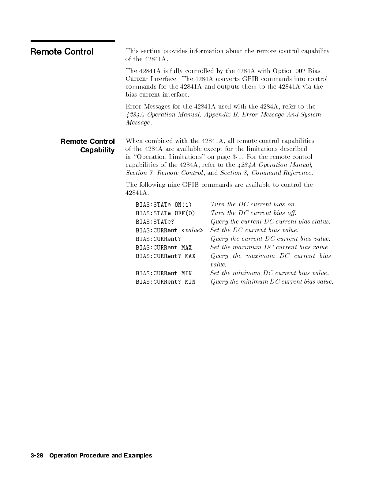
Remote
Control
This
section
of
the 42841A
pro
.
vides
information
ab
out
the
remote con
trol capabilit
y
Remote
Capability
Control
The 42841A
Curren
tIn
terface.
commands
bias curren
Error
Messages for
4284A
Message
When
of
in
Op
er
.
com
the 4284A
\Op
eration
capabilities
Se
ction
7,
R
The
follo
wing
42841A
.
BIAS:STATe
BIAS:STATe
BIAS:STATe?
BIAS:CURRent
BIAS:CURRent?
BIAS:CURRent
BIAS:CURRent?
BIAS:CURRent
BIAS:CURRent?
is fully
The
for
the
42841A
tin
terface.
the 42841A
ation
Manual,
bined
with
are a
v
ailable
Limitations"
of
the
4284A,
emote Contr
nine
GPIB
ON(1)
OFF(0)
<
MAX
MIN
controlled
4284A
and
App
the
42841A
except
on
refer
ol
,
and
commands
value
>
MAX
MIN
by
con
outputs
used with
endix
,
for
page
to
Se
T
urn
T
urn
Query
Set
the
Query
Set
the
Query
value.
Set
the
Query
the 4284A
v
erts
GPIB
them
the
B,
Err
all
remote con
the
limitations
3-1.
F
or
the
4284A
ction
8,
are
a
v
the
DC
curr
the
DC
current
the
curr
DC
curr
the
curr
maximum
the
maximum
minimum
the
minimum
with Option
commands
to
the
4284A,
or
Message
trol capabilities
the
remote
Oper
ation Manual,
Command
ailable
ent
to con
bias
bias o.
ent
DC
curr
ent
bias
ent
DC
DC
curr
DC
curr
DC
002
in
to
42841A via
refer
to
A
nd
System
describ
R
con
efer
ed
trol
enc
trol the
on.
ent
bias
value.
curr
ent
bias
ent
bias
DC
curr
ent
bias
curr
ent
Bias
con
the
e
ent
bias
trol
the
.
status.
value.
value.
bias
value.
value.
3-28 Operation Procedure and Examples
Page 67
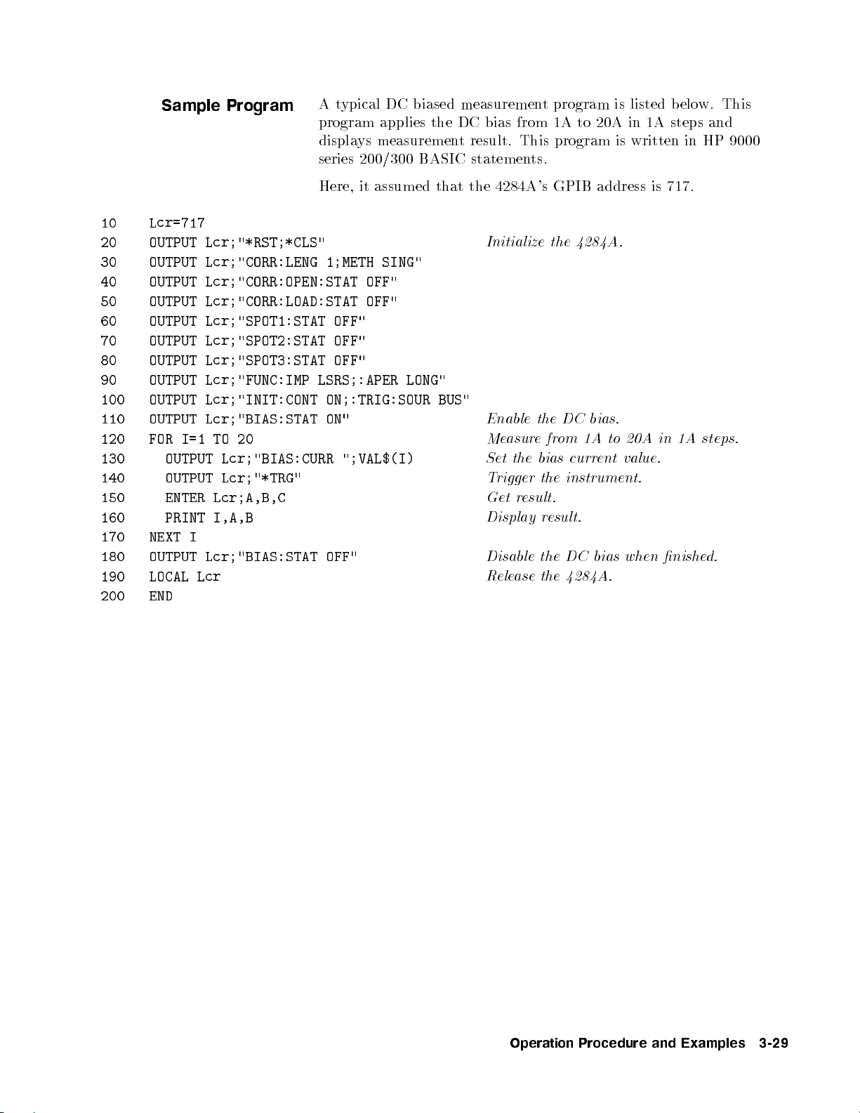
Sample
Program
A
t
ypical
program
displays
series
200/300
Here,
it
DC
biased
applies the
measurement
BASIC
assumed
that
measuremen
DC bias
from 1A
result. This
statemen
the
4284A's
t
program
program
ts.
GPIB
to 20A
address is
is
listed
in 1A
is
written
belo
w. This
steps and
in
HP
717.
9000
10
Lcr=717
20 OUTPUT
30
40
OUTPUT
OUTPUT
50 OUTPUT
60
70
80
90
100
110
120
OUTPUT
OUTPUT
OUTPUT
OUTPUT
OUTPUT
OUTPUT
FOR
I=1
130 OUTPUT
140
150
160
170
180
190
200
OUTPUT
ENTER
PRINT
NEXT
OUTPUT
LOCAL
END
I
Lcr
Lcr;"*RST;*CLS"
Lcr;"CORR:LENG
Lcr;"CORR:OPEN:STAT
1;METH
SING"
OFF"
Lcr;"CORR:LOAD:STAT OFF"
Lcr;"SPOT1:STAT
Lcr;"SPOT2:STAT
OFF"
OFF"
Lcr;"SPOT3:STAT OFF"
Lcr;"FUNC:IMP
Lcr;"INIT:CONT
Lcr;"BIAS:STAT
TO
20
LSRS;:APER
ON;:TRIG:SOUR
ON"
Lcr;"BIAS:CURR ";VAL$(I)
Lcr;"*TRG"
Lcr;A,B,C
I,A,B
Lcr;"BIAS:STAT
OFF"
LONG"
BUS"
Initialize
Enable
Me
asur
Set the
T
rigger
Get
r
esult.
Display
Disable
R
ele
ase
the 4284A.
the
DC
bias.
e
fr
om
1A
bias curr
the
instrument.
result.
the
DC
the 4284A.
to 20A
ent
value.
bias
when nishe
in 1A
steps.
d.
Operation Procedure and Examples 3-29
Page 68

Page 69
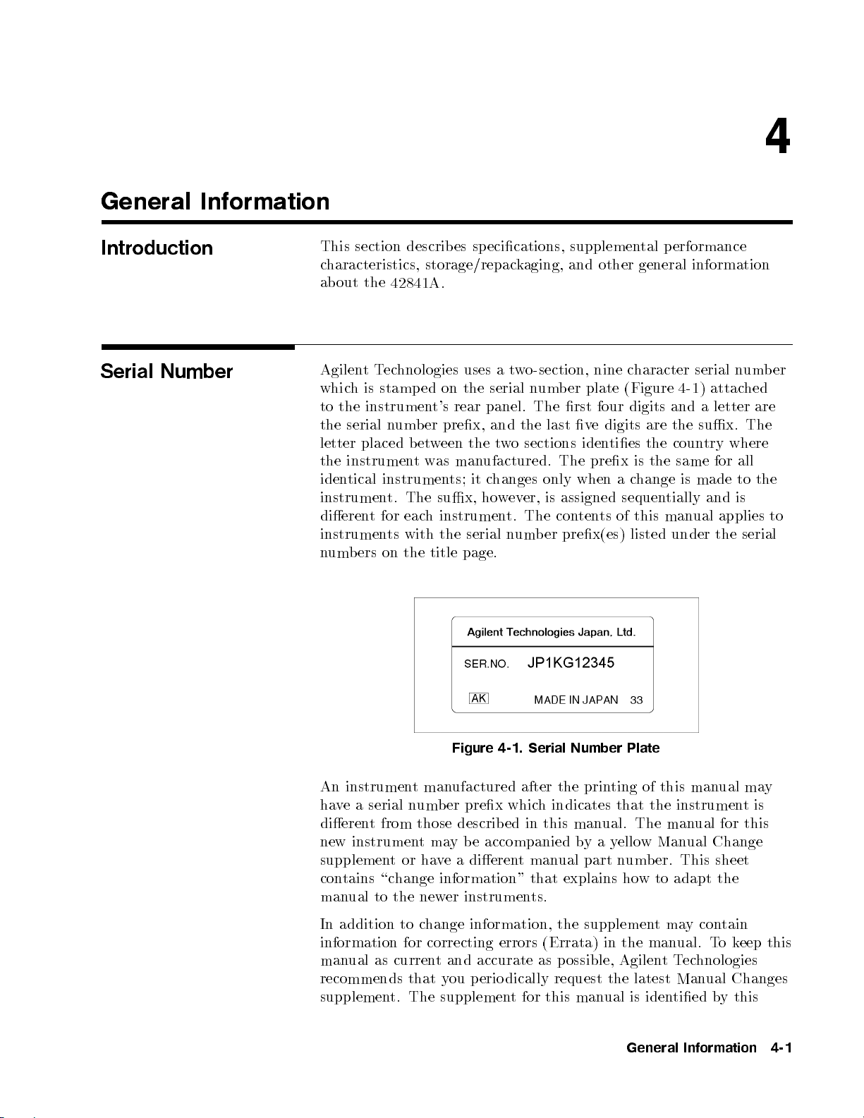
General Information
Introduction
This
section
c
haracteristics,
ab
out
the
42841A
describ
es
sp
storage/repack
.
ecications,
aging, and
supplemen
other general
tal
p
4
erformance
information
Serial
Number
Agilent
whic
to
the
letter
the
iden
Tec
h
is
the
instrumen
serial
placed
instrument
tical
instrumen
dieren
t
instrumen
n
um
b
ers
hnologies uses
stamp
ed
on
t's
n
um
b
er
prex,
b
et
w
een
was
instrumen
t.
The
sux,
for
eac
h
instrumen
ts
with
the
on
the
title
a
t
w
o-section,
the
serial
n
rear
panel.
and
the
the
t
w
o
sections
manufactured.
ts;
it
c
hanges
ho
w
ev
er,
t.
The
serial
n
umb
page.
Figure 4-1.
Serial Number
um
The
last
only
is
con
er
nine
b
er
plate
rst
four
ve
digits are
iden
The
prex
when a
assigned
ten
ts
prex(es)
c
(
digits
ties
change
sequen
of
Plate
haracter
Figure
and
the sux.
the
is
the
tially
this
man
listed
under
4-1
coun
same
is
serial
) attac
a
letter are
try
for
made
and
ual
applies
the
n
um
hed
The
where
all
to
the
is
serial
b
er
to
An instrumentman
have a serial n
dierent
from those described in this man
new instrumen
supplementorha
contains \c
hange information" that explains ho
manual to the new
ufactured after the prin
umber prex whic
tma
y be accompanied b
ve
a dieren
t manual part n
er instrumen
ting of this man
h
indicates that the instrumen
ual. The man
yay
ellow Man
ual Change
umber. This sheet
w to adapt the
ts.
ual ma
tis
ual for this
y
In addition to change information, the supplementmaycontain
information for correcting errors (Errata) in the manual. Tokeep this
manual as current and accurate as p ossible, AgilentTechnologies
recommends that you perio dically request the latest Manual Changes
supplement. The supplement for this manual is identied by this
General Information 4-1
Page 70
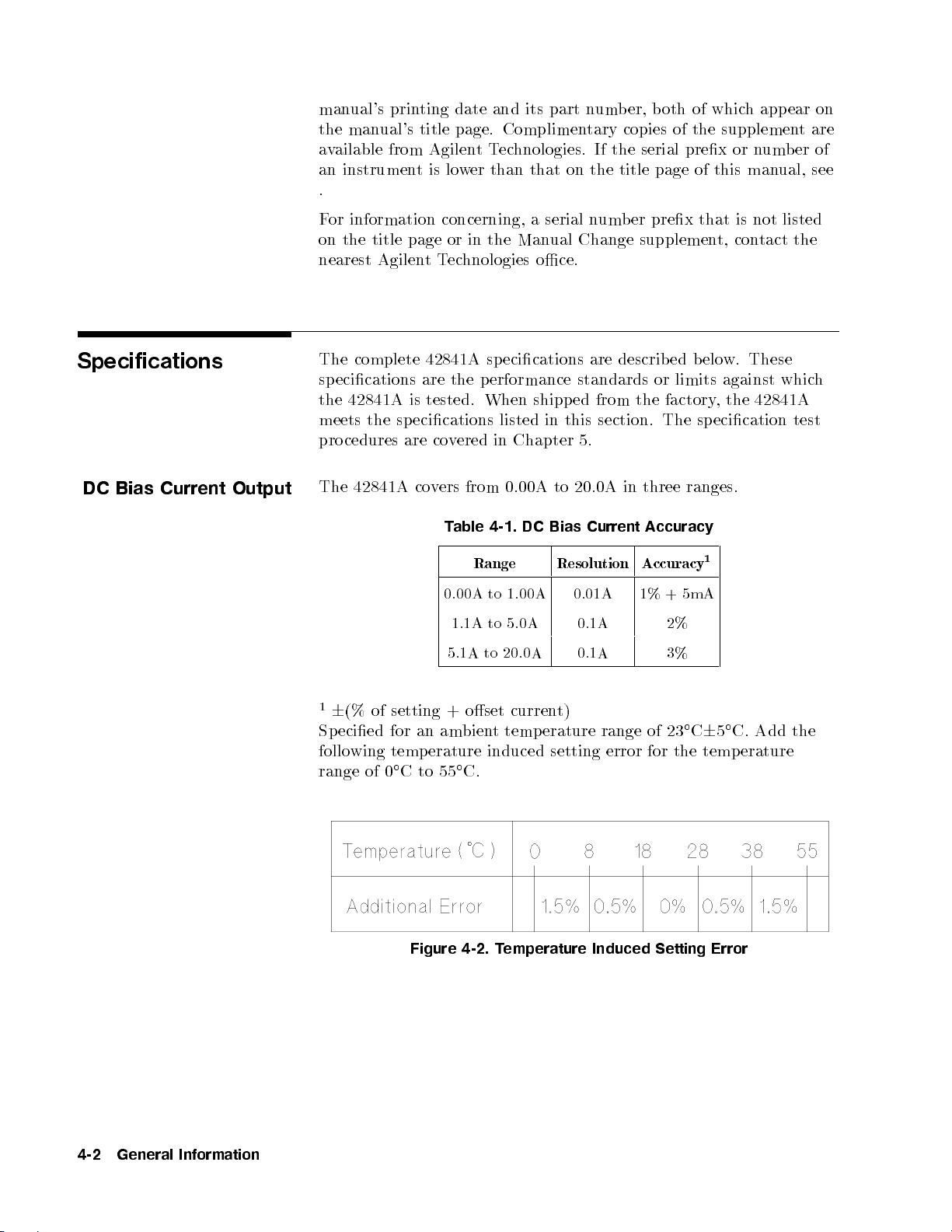
Specifications
DC
Bias
Current
Output
manual's
the
a
v
ailable
man
ual's
printing
from Agilen
an instrumen
.
F
or
information
on the
nearest
The
sp
the
meets
pro
The
title page
Agilen
complete
ecications
42841A
the
sp
cedures
are
42841A
date and
title
page.
tis
lo
w
er
concerning,
or in
t
T
ec
hnologies
42841A
are the
is
tested.
ecications
cov
ered
co
v
ers
from
T
able 4-1.
its part
Complimen
tT
echnologies.
than
that
a
serial
the Man
ual
oce.
sp
ecications
performance
When
listed
in
Chapter
shipp
in
0.00A
DC Bias
num
tary
If the
on
the
n
um
Change
are
standards or
ed
from
this
section. The
5.
to
20.0A
Current
b
er,
b
oth
copies
serial prex
title
page
b
er prex
supplemen
describ
the
factory
in
three
Accuracy
of
whic
of
the
supplemen
of
this
that is
t,
ed b
elow.
limits
against
,
specication
ranges.
h
or n
manual,
not listed
con
These
the
42841A
app
umb
tact
ear
t
er
the
whic
test
on
are
of
see
h
1
6
(% of
Sp
ecied
follo
range
wing
of 0
0.00A
5.1A
setting +
for
an
ambien
temp
erature
C
to 55
Figure 4-2. T
Range Resolution Accuracy
0.01A 1%
0.1A 2%
0.1A 3%
t)
erature range
setting
error
of 23
for
1.1A
oset
C.
to
1.00A
to
5.0A
to 20.0A
curren
ttemp
induced
emperature Induced Setting Error
+
5mA
the
1
C
6
temp
C.
5
Add
erature
the
4-2 General Information
Page 71
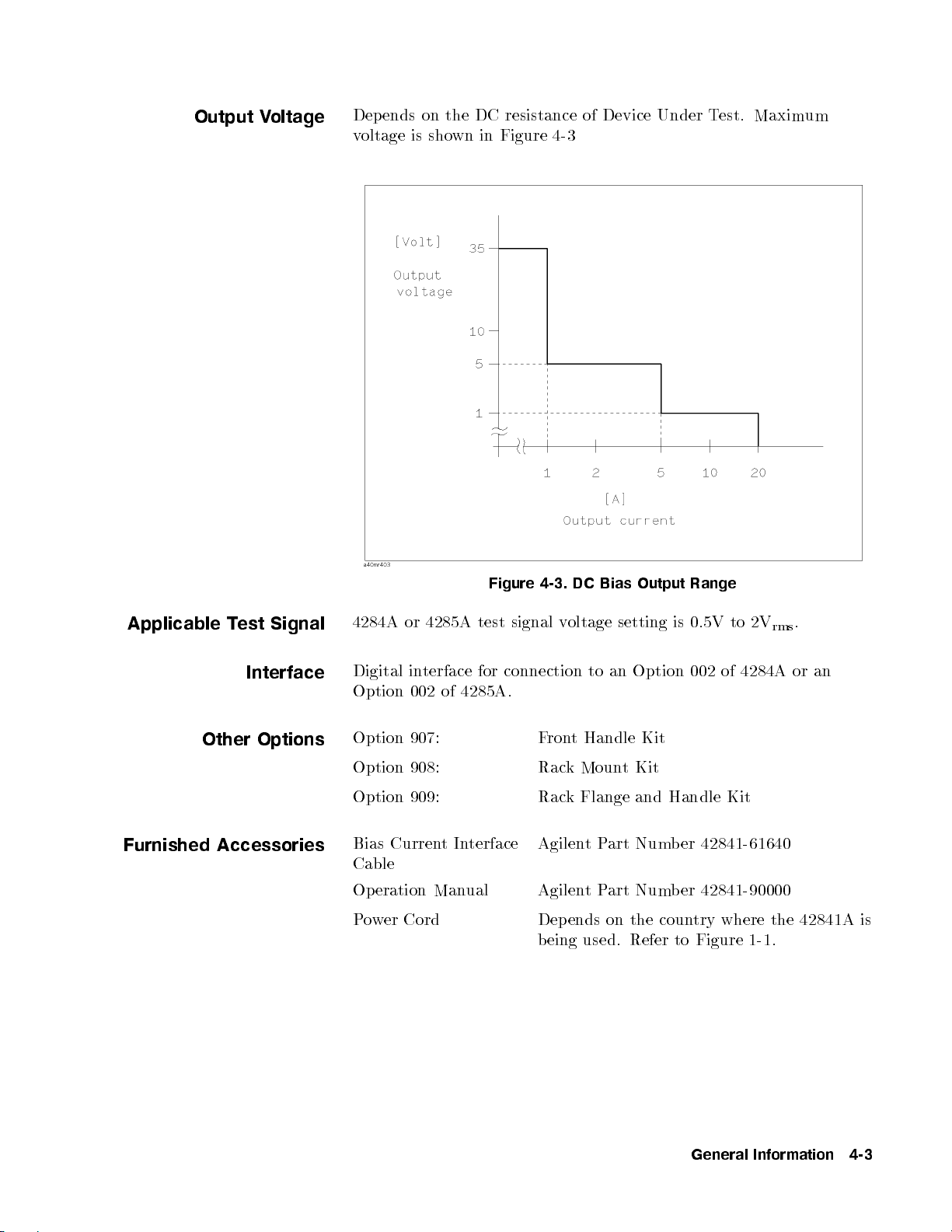
Output
V
oltage
Dep
ends
v
oltage is
on
the
shown
DC
resistance
in Figure
4-3
of
Device
Under
T
est. Maxim
um
Applicable
Test
Signal
Interface
Other
Options
Furnished Accessories
4284A
Digital
Option
Option
Option
Option
Bias Curren
or
4285A test
interface
002
of
907:
908:
909: Rac
tIn
Cable
Operation Man
Power Cord
Figure
4-3.
signal
v
oltage
for connection
4285A
.
F
ron
Rac
k
k Flange
terface
AgilentP
ual Agilent
Depends on the coun
being used. Refer to Figure 1-1.
DC
Bias
to
t
Handle
Moun
Part Num
Output
setting
an
Option
Kit
t
Kit
and
art Num
Range
is
0.5V
002
Handle
to
of
Kit
4284A
2V
rms
.
or
ber 42841-61640
ber 42841-90000
try where the 42841A is
an
General Information 4-3
Page 72
T
est
Fixtures
42842A
Bias
Curren
t
T
est
Fixture
(for
4284A
20A
system)
Other Accessories
Line
Line
P
o
wer
Consumption
Operating
T
emperature
Operating
Operating
Dimensions
V
oltage
Frequency
Humidity
Altitude
42842B
42842C
42843A
100,
120,
47
to
66Hz
600V
A
0C
to
RH
0
m
to
426(W)
Bias
Curren
Bias
Curren
Bias Curren
220V
6
max.
C
55
95%
at
40
2000
m
b
y 177(H)
10%,
C
t
T
est
t
T
est
t Cable
240V
by
498(D)
Fixture
Fixture
(for 40A
+5%-10%
(mm)
(for
(for
system)
4284A
4285A)
40A system)
Supplemental
P
erformance
Characteristics
42841A Measurement
Accuracy
(used
Weight
for
4284A)
18
kg
The
42841A
listed
b
sp
ecications,
information for
The measuremen
when
used
elo
w.
with
measuremen
Supplemen
but
are
t
ypical
the op
erator.
t range
the
42841A and
t
accuracy represen
tal
of the
of inductance(L), impedance(
Resistance; Rs), D, and
and 42842A/B
L and
jZj
Ae=
are as follows:
Accuracy :
+
A
A
1
0
A
e
[%
of r eading
when the 42841A is used with the 4284A
(for L accuracy; Dx
Where,
tc
haracteristics
p
erformance
c
haracteristics
4284A is
42842A/B.
jZj
), series resistance (Equiv
c
haracteristics are
included
limited to
Measuremen
0.1)
]
as
10
are
not
supplemen
and
100
t
accuracy
alentSeries
tal
4-4 General Information
Page 73
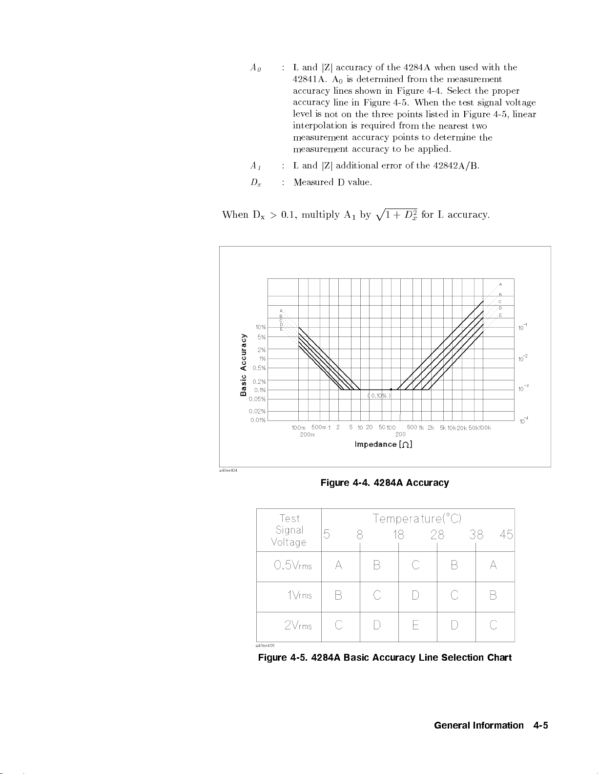
A
A
D
:
Land
j
Z
j
0
42841A
accuracy
accuracy
lev
el is
in
terpolation
measuremen
measuremen
: L
1
x
and
:
Measured
accuracy
.A
0
lines sho
line in
not
j
Z
j
additional
D
is
on
t
t
of
the
determined from
wn in
Figure 4-4
Figure
the
is
required
accuracy
accuracy
three
4-5
p
p
to
oin
from
oin
error
v
alue.
4284A
when
the measuremen
.
When
ts
listed
the
ts
to
determine
b
e
applied.
of
the
42842A/B.
used
.
Select
the
test
in
nearest
with
the
signal
Figure
t
w
the
o
t
prop
4-5
the
er
v
oltage
, linear
When
D
>
0.1,
m
x
ultiply
Figure 4-4.
A
b
y
1
4284A Accuracy
p
2
+
D
for
L
x
accuracy
.
1
Figure 4-5. 4284A Basic Accuracy Line Selection Chart
General Information 4-5
Page 74
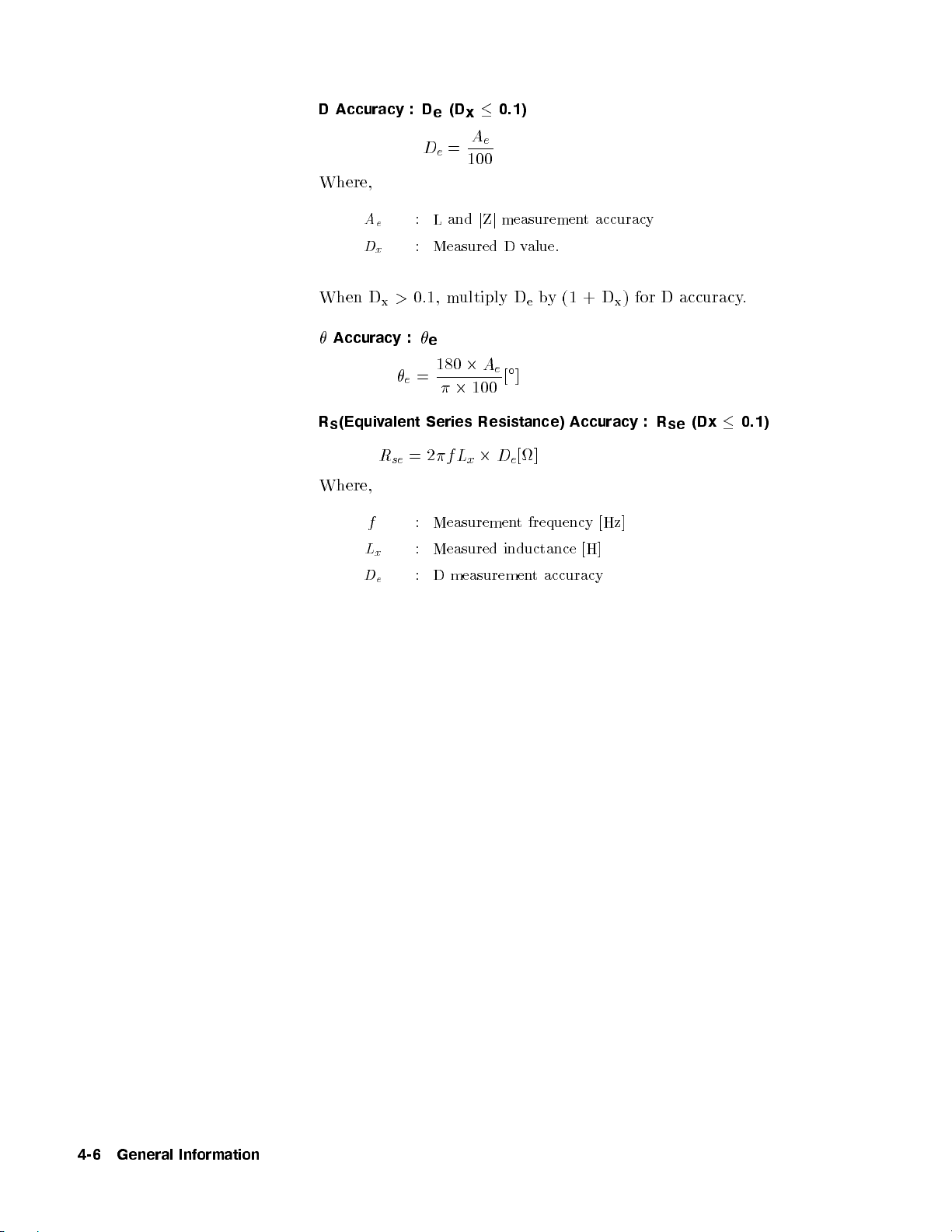
D Accuracy
Where,
:D
De=
e(Dx
A
100
0.1)
e
A
D
When
D
Accuracy
Rs(Equiv
Where,
f
L
D
e
x
>
x
e=
alent
Rse=
x
e
:
L and
j
Z
j
measuremen
:
Measured
0.1,
:
e
m
180
2
ultiply
2
A
e
100
D
[]
Series Resistance)
2
L
x
D
e
inductance
2
f
:
Measuremen
:
Measured
:
D
measurement
v
alue.
b
y
D
e
[]
t
frequency
accuracy
t accuracy
(1
+
D
x
Accuracy :
[Hz]
[H]
)
for
D
accuracy
R
se
(Dx
.
0.1)
4-6 General Information
Page 75
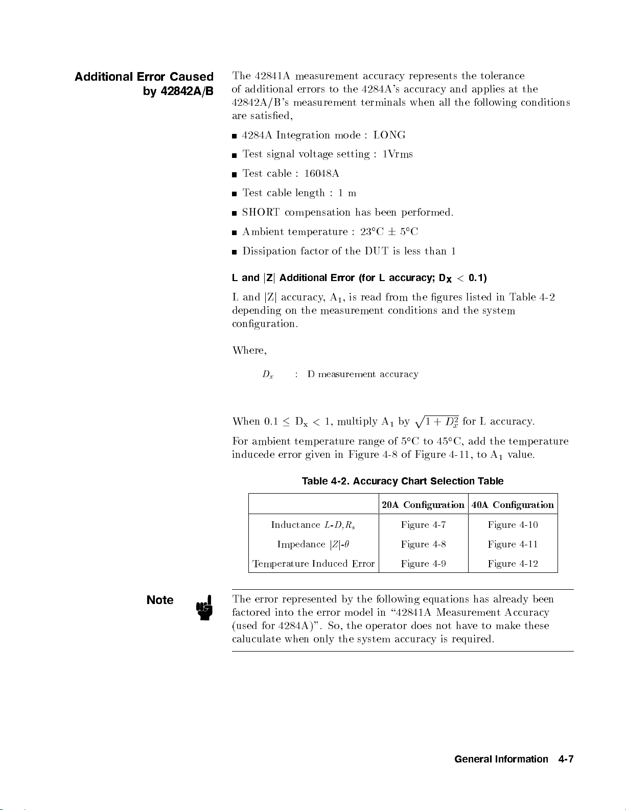
Additional
Error
Caused
b
y 42842A/B
The
42841A
of
additional errors
measuremen
to the
42842A/B's measuremen
are
satised,
t
accuracy
represen
4284A's accuracy
t terminals
when all
ts
the
tolerance
and applies
the
follo
wing
at the
conditions
4284A
T
T
T
SHOR
Am
Integration
est
signal
est
cable
est cable
T
bien
t
comp
temp
Dissipation
L
and
j
Z
j
Additional
L
and
j
Z
j
accuracy
dep
ending
on
conguration.
Where,
D
x
When
F
inducede
or am
0.1
bient
error
v
oltage
:
16048A
length :
ensation
erature
factor of
the
measuremen
:
D
measuremen
<
D
x
temp
erature
giv
en
mode
setting
1
m
:
the
Error (for
,
is
,
A
1
1,
m
ultiply A
in
Figure
: LONG
:
has
b
C
23
DUT
read
t
range
1V
rms
een
p
erformed.
C
6
5
is
less
than
L accuracy;
from
the
gures
t
conditions and
accuracy
p
b
1
y
1
of
4-8
5
of
+
C
to 45
Figure 4-11
1
<
D
x
2
D
x
C,
0.1)
listed
in
the system
for
L
accuracy
add the
,to
A
1
T
able
4-2
.
temperature
v
alue.
Note
T
able 4-2.
Inductance
Imp
edance
L-D,R
j
Z
j
-
Accuracy
s
Chart
20A
Conguration
Figure
Figure
Selection
4-7
4-8
T
40A
able
Figure
Figure
Temperature Induced Error Figure 4-9 Figure 4-12
The error represen
factored in
to the error mo del in \42841A Measuremen
(used for 4284A)". So, the op erator does not ha
caluculate when only the system accuracy
ted b
y the following equations has already
vetomak
is required.
General Information 4-7
Conguration
4-10
4-11
been
t Accuracy
ethese
Page 76
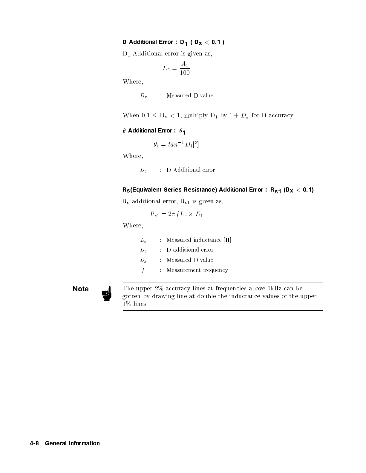
D Additional
D1Additional
Where,
Error :
error is
D1=
D
1
A
100
(Dx<
given
1
as,
0.1
)
D
x
When 0.1
Additional
1=
Where,
D
1
Rs(Equiv
alent
Rsadditional
R
s
Where,
L
x
D
1
D
x
f
:
Measured
<
D
x
Error
:
tan
:
D
Additional
Series
error,
=
2
1
:
Measured
:
D
additional
:
Measured
:
Measuremen
D
1,
multiply
1
0
1
D1[]
Resistance)
is
R
s1
2
f
D
L
x
inductance
D
v
alue
D
error
giv
en
1
error
v
alue
t
frequency
by
1+
1
Additional
as,
[H]
D
x
Error
for D
accuracy.
:
R
s1
(Dx<
0.1)
Note
4-8 General Information
The upp
gotten
1%
lines.
by
er
2%
dra
accuracy
wing
line
lines
at
at
double
frequencies
the
inductance
ab
o
v
e
1kHz
v
alues
can
of
the
b
e
upp
er
Page 77
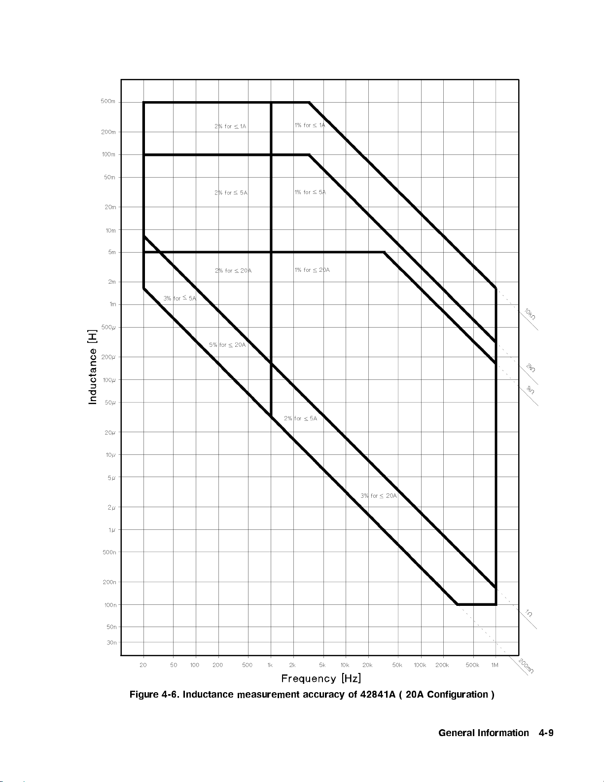
Figure 4-6. Inductance measurement accuracy of 42841A ( 20A Configuration )
General Information 4-9
Page 78
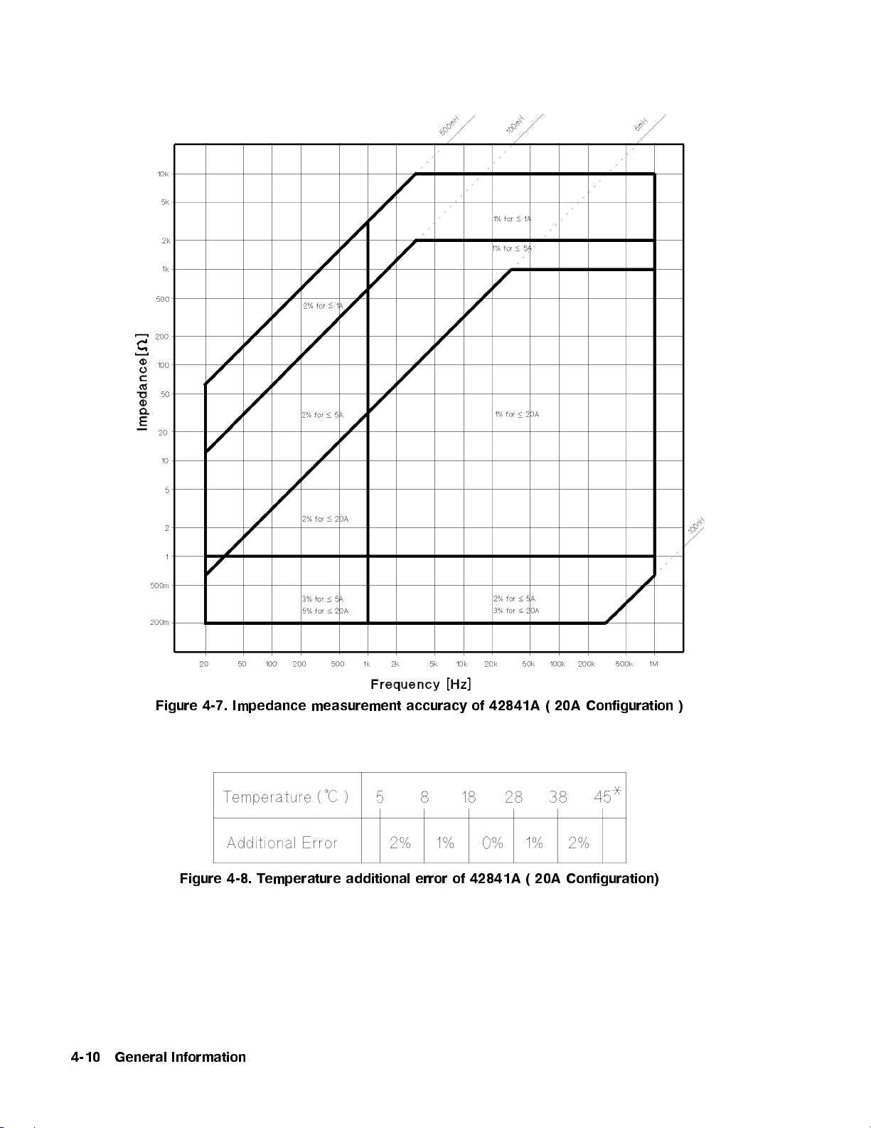
Figure
4-7.
Impedance
measurement
accuracy
of
42841A
(
20A
Configuration
)
Figure 4-8. T
4-10 General Information
emperature additional error of 42841A ( 20A Configuration)
Page 79
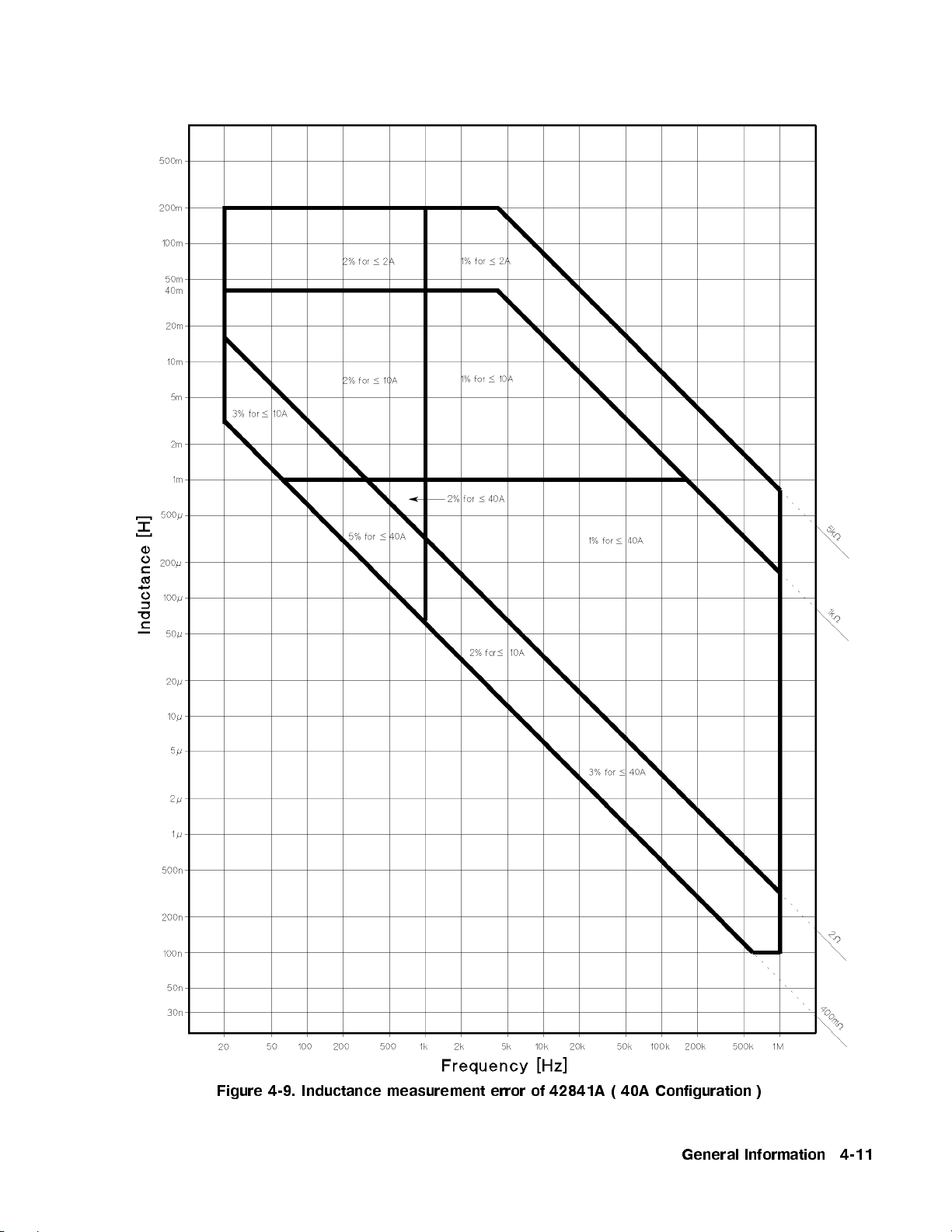
Figure 4-9. Inductance measurement error of 42841A ( 40A Configuration )
General Information 4-11
Page 80
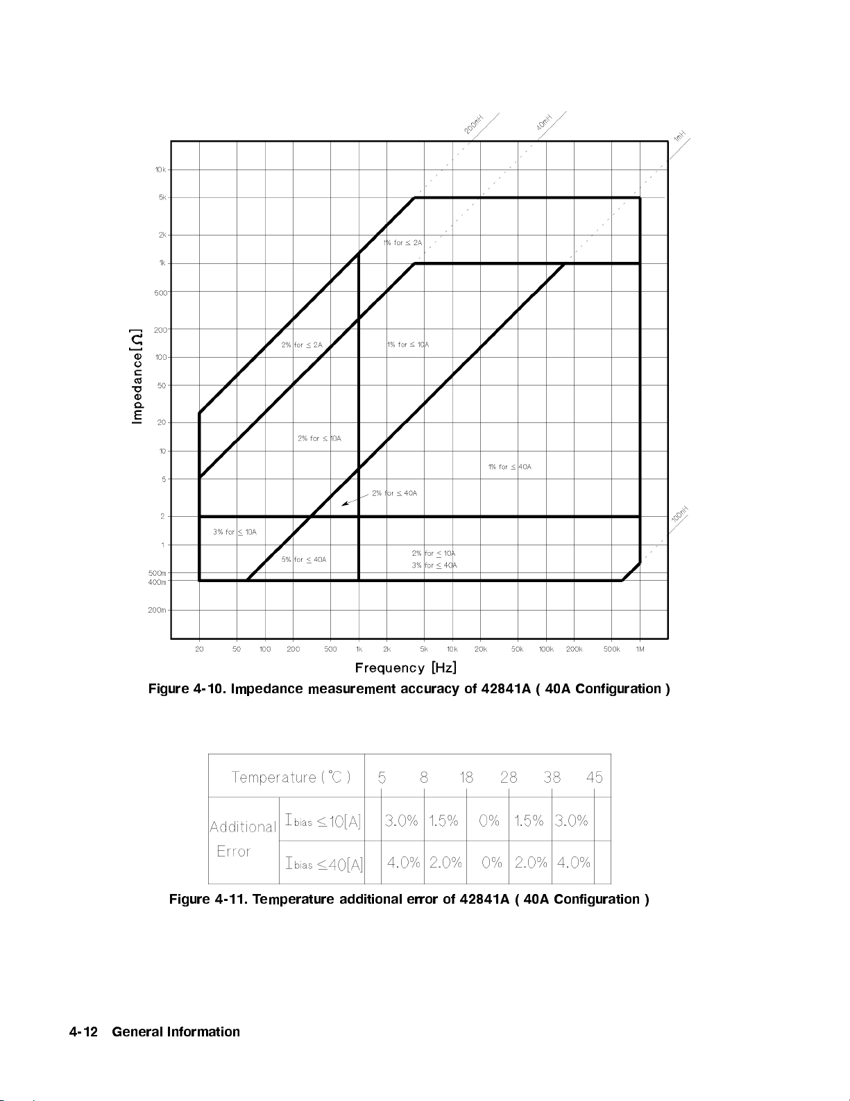
Figure
4-12 General Information
4-10.
Figure 4-11. Temperature additional error of 42841A ( 40A Configuration )
Impedance
measurement
accuracy
of
42841A
(
40A
Configuration
)
Page 81
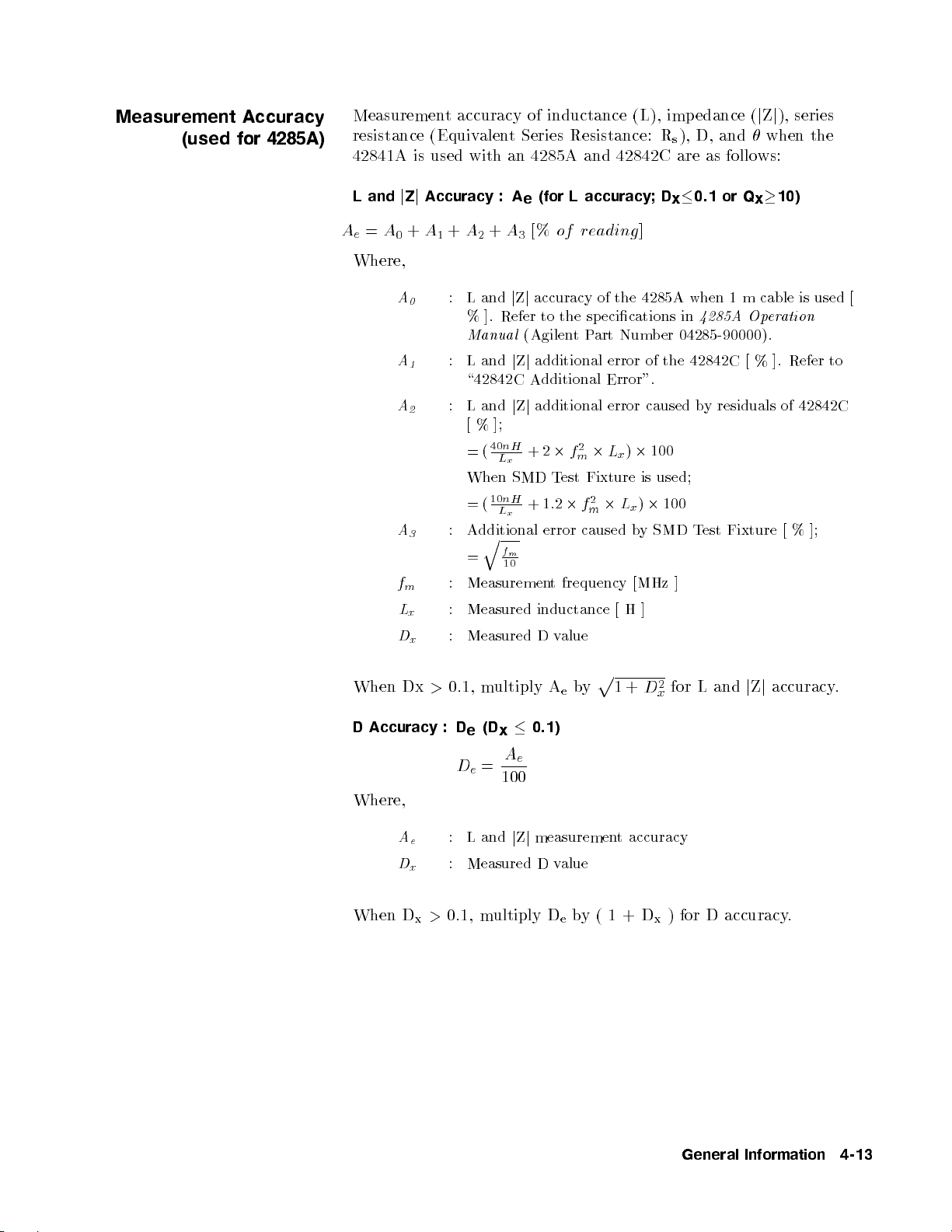
Measurement
(used
Accuracy
for 4285A
Measuremen
resistance
)
42841A is
t
accuracy
(Equivalen
used with
of
inductance
t Series
an 4285A
(L),
Resistance: R
and
42842C
imp
),
s
are
edance
D, and
as
follo
(
j
ws:
Z
when
j
), series
the
L
and
Ae=
Where,
j
Z
A0+
A
A
A
A
f
m
L
D
j
Accuracy :
A1+
:
0
:
1
:
2
:
3
:
:
x
: Measured
x
A
e
A2+
A3[%
L
and
j
Z
j
accuracy
%
].
Refer
Manual
L
\42842C
L
[
%
=
When
=
Additional
=
and
and
40
(
10
(
q
];
L
L
j
Z
j
Z
nH
x
SMD
nH
x
f
m
10
(Agilen
j
additional
Additional
j
additional
+
+
Measuremen
Measured
(for
L accuracy;
of
reading
of
to
the
sp
t
P
art
2
2
f
m
Test
Fixture is
2
:
2
2
f
m
caused
t
frequency
2
2
1
error
inductance
D
v
alue
D
]
the
4285A
ecications
Num
b
er
error
of
the
Error".
error caused
)
L
2
100
x
used;
2
)
L
2
100
x
b
y
SMD
[MHz
[
H
]
x
0.1 or
when
in
1
4285A
Q
m cable
04285-90000).
42842C
b
y
residuals
Test
Fixture [
]
Op
[
x
%
er
10)
ation
].
of
is used
Refer
42842C
%
];
[
to
When
D
Dx
>
Accuracy :
Where,
A
e
D
x
When Dx>
0.1,
m
ultiply
D
e(Dx
De=
:
Land
0.1)
A
e
100
j
Z
j
measuremen
: Measured D v
0.1, m
ultiply D
p
b
y
A
e
alue
by(1+D
e
1
+
D
t
accuracy
2
for
L
and
x
) for D accuracy
x
j
Z
j
accuracy
.
.
General Information 4-13
Page 82
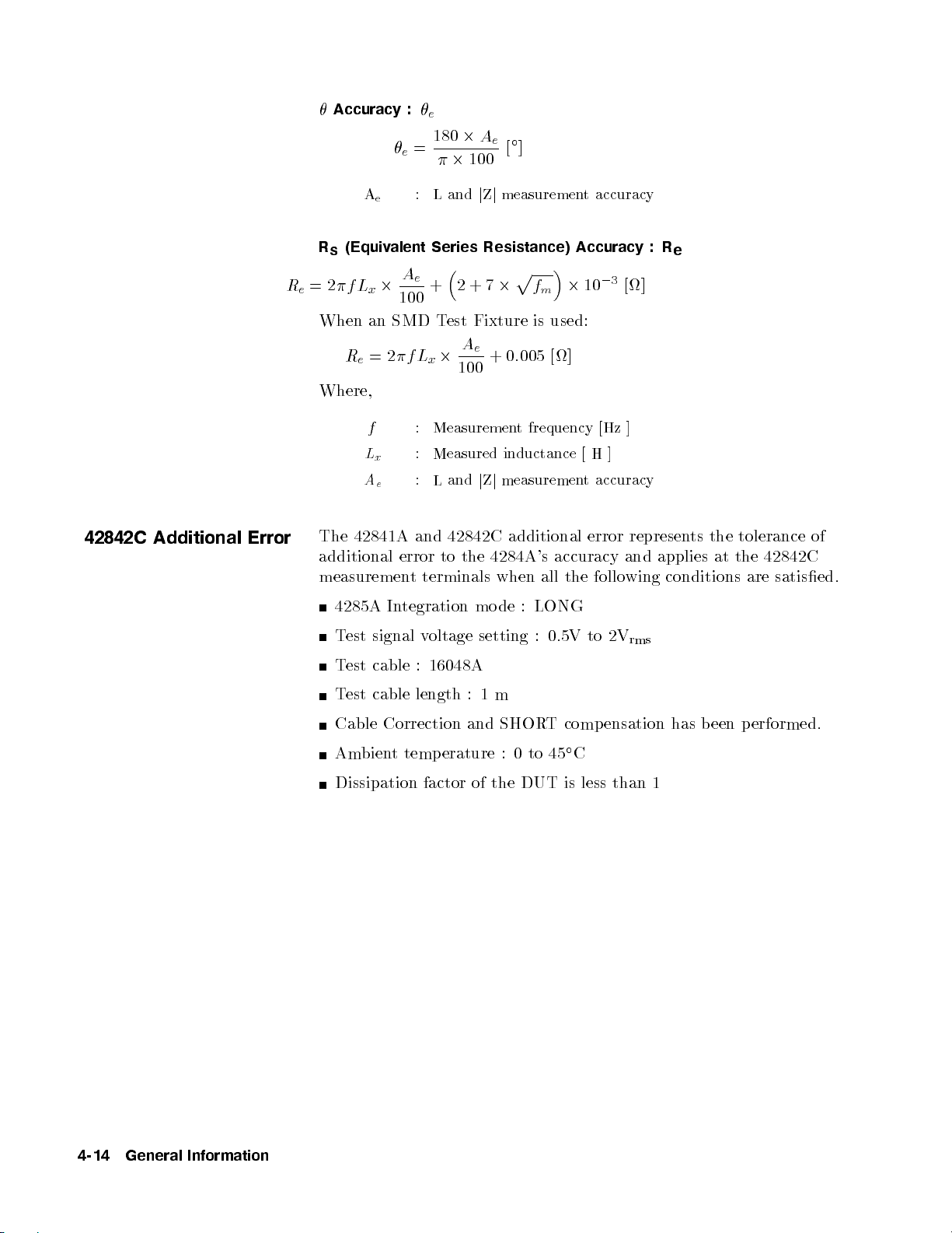
Accuracy
:
e=
e
180
2
A
e
100
[]
2
42842C
Additional Error
Rs(Equiv
Re=
2
f
When
Re=
Where,
The
42841A and
additional error
measuremen
4285A
Test
A
e
alent Series
2
L
x
100
an
SMD
2
f
L
x
A
e
In
signal
: L
and
j
A
e
+2
+
T
est
Fixture
A
e
2
f
L
x
100
:
Measuremen
:
Measured
:
L
and
j
42842C additional
to the
t
terminals
tegration
v
mo
oltage
Z
j
measurement
accuracy
Resistance) Accuracy
p
f
7
2
is
+
0
:
005
t
frequency
inductance
Z
j
measuremen
m
used:
[]
2
[
0
3
10
[Hz
H
]
t
accuracy
error
4284A
's
accuracy
when
all
the
follo
de
:
LONG
setting
:
0.5V
to
2V
:R
[]
]
represen
and
applies
wing
rms
e
ts
the
at
conditions
tolerance
the
42842C
are satised.
of
T
est
cable
:
16048A
T
est
cable
length
Cable Correction
Am
bien
t
temperature
Dissipation
factor
:
1
and
of
m
SHOR
:0
the
T
to 45
DUT
comp
C
is
less
ensation
than
1
has
b
een
p
erformed.
4-14 General Information
Page 83
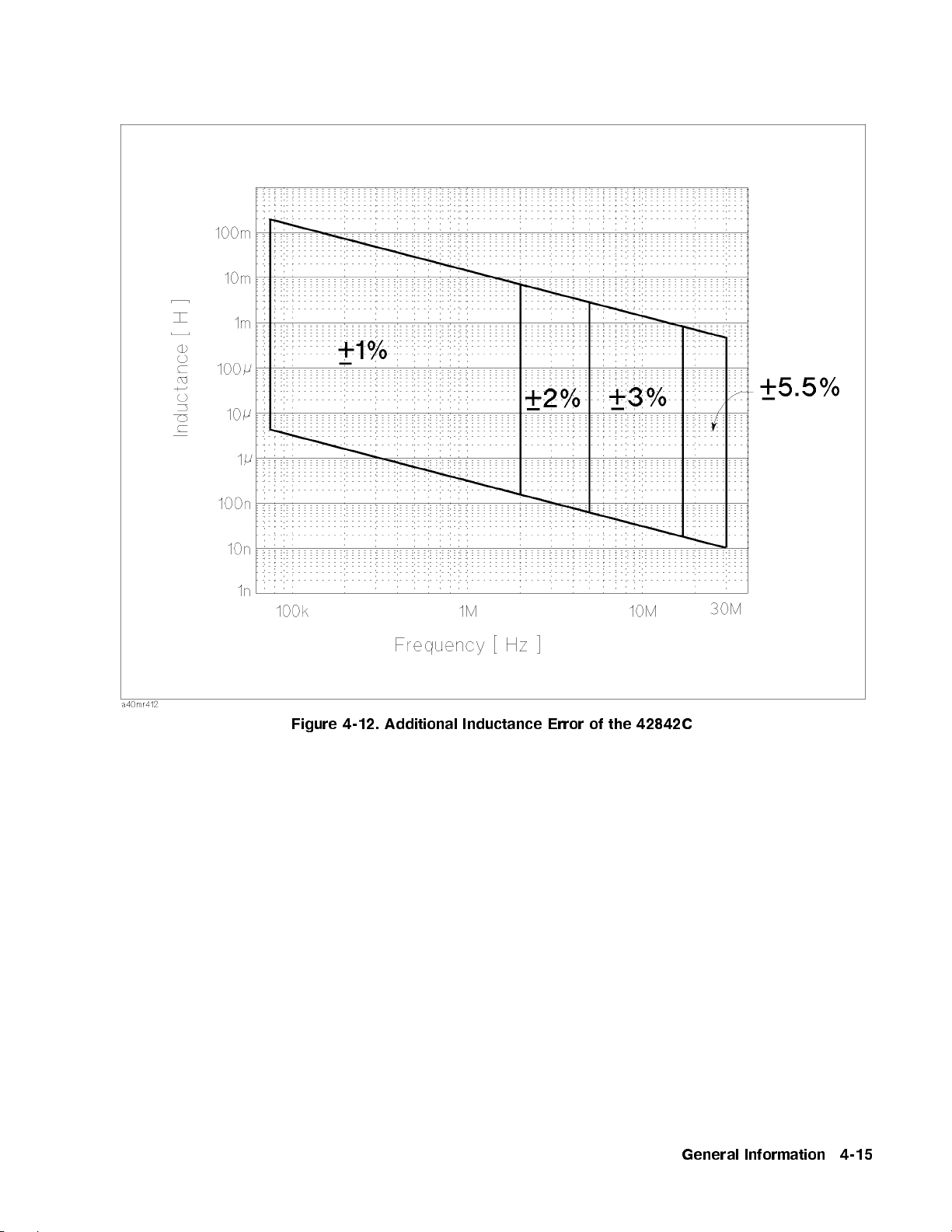
Figure
4-12.
Additional Inductance
Error of
the 42842C
General Information 4-15
Page 84
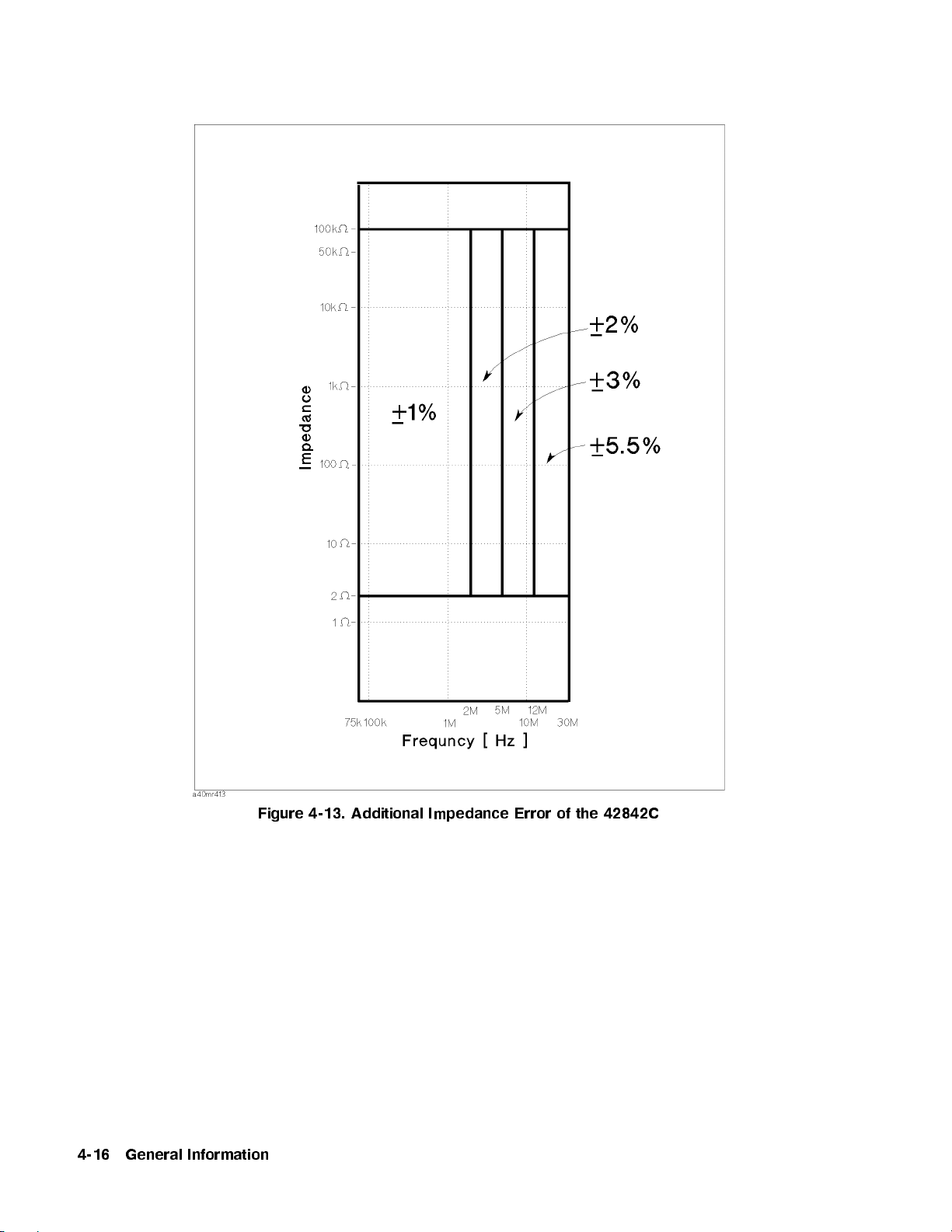
4-16 General Information
Figure
4-13. Additional
Impedance Error
of the
42842C
Page 85
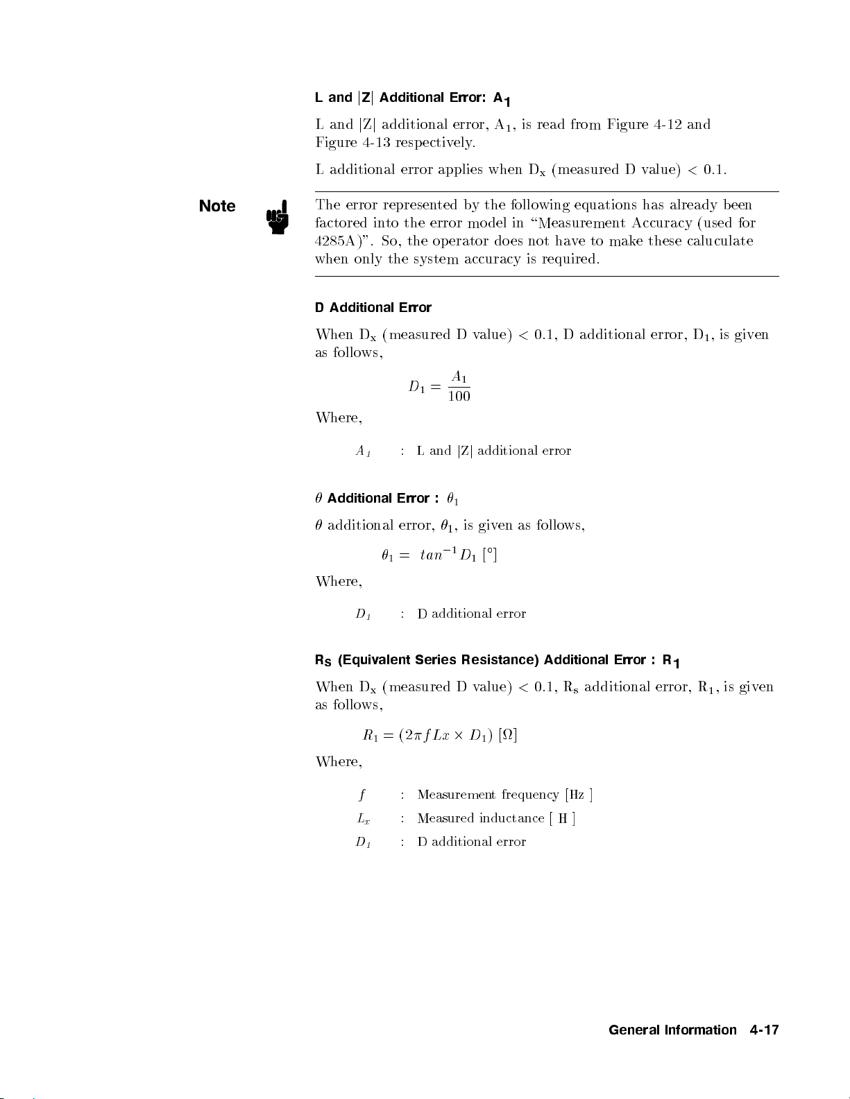
L and
L
and
Figure
j
Z
j
Additional
j
Z
j
additional error,
4-13
resp
ectiv
Error: A
ely
.
A
1
,
1
is read
from Figure
4-12 and
Note
L
additional
The
error
factored
4285A
)". So,
when
only
D
Additional Error
error
represen
in
to
the
the
ted
error
the op
system
applies
erator do
When Dx(measured D
as
follo
ws,
D1=
A
100
Where,
A
Additional
additional
1
Error
error,
1=
:
L
and
j
:
1
,
1
0
1
tan
when
b
y
the
follo
mo
del
in
es
accuracy
v
alue)
<
1
Z
j
additional error
is
giv
en
as
D1[]
(measured
D
x
wing
equations
\Measurement
not
ha
v
e
to
is
required.
0.1,
D
additional
follo
ws,
D
v
alue)
has
already
Accuracy (used
mak
e
these
error,
<
0.1.
b
een
for
caluculate
,is
D
giv
1
en
Where,
D
1
Rs(Equiv
When
as
D
follows,
R1=(2
Where,
f
L
x
D
1
:
D
alent
Series
(measured
x
additional
D
f
Lx
2
error
Resistance)
v
alue)
<
) []
D
1
: Measurement frequency [Hz ]
: Measured
inductance [ H ]
: D additional error
Additional
0.1,
R
s
Error
additional
:
R
error,
1
,
is
R
giv
1
en
General Information 4-17
Page 86
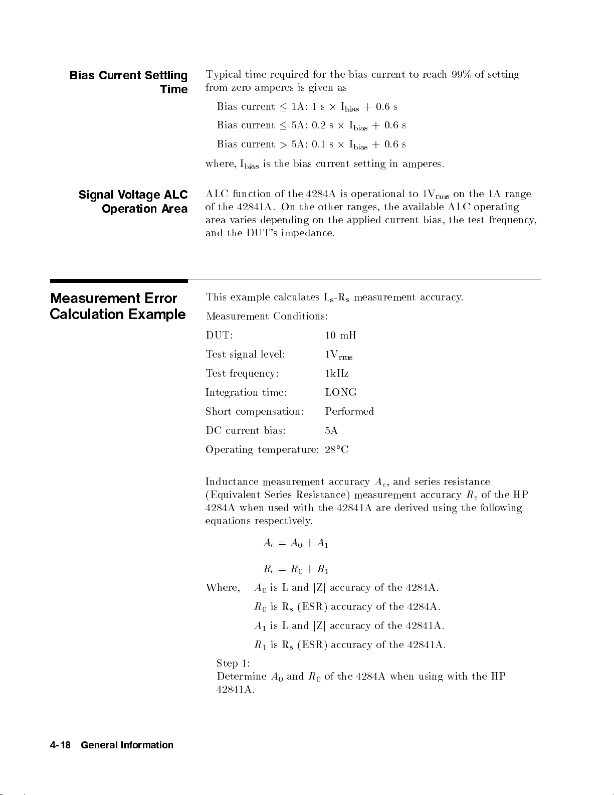
Bias
Current
Settling
Time
T
ypical
from
zero amp
Bias curren
time
required
eres is
t
1A: 1
for
given
s
the
2
as
I
bias
bias
curren
+ 0.6
t
to
reach
99% of
setting
s
Signal
Voltage
Operation
Measurement
Calculation
Example
ALC
Area
Error
Bias
curren
Bias
current
where, I
bias
is the
ALC function
of
the
42841A
area
v
aries
dep
and the
This
DUT's imp
example
Measuremen
DUT:
T
est
signal
T
est
frequency:
In
tegration
Short
comp
lev
time:
ensation:
t
5A: 0.2
>
5A:
bias curren
of the
.
On
the
ending
edance.
calculates
t
Conditions:
el:
s
2
0.1 s
2
4284A is
other
on
the
L
s-Rs
10 mH
1V
rms
1kHz
LONG
P
erformed
+
0.6
+
0.6 s
in
the
s
amp
a
I
bias
I
bias
t setting
op
erational
ranges,
applied curren
measuremen
eres.
to
1V
v
ailable
tbias,
t
accuracy
rms
ALC
the test
on the
op
.
1A range
erating
frequency
,
DC
curren
Op
erating
Inductance
(Equiv
4284A
alent
when
equations
Where,
Step 1:
Determine
42841A.
t
bias:
temp
erature:
measuremen
Series Resistance)
used
with
resp
ectiv
Ae=
A
Re=
R
is L and
A
0
ely
0
0
5A
C
28
t
accuracy
A
measuremen
the
42841A
are deriv
.
+
A
1
+
R
1
j
Z
j
accuracy of the 4284A.
,
and
e
series
t
accuracy
ed using
R0is Rs(ESR) accuracy of the 4284A.
A1is L and
jZj
accuracy of the 42841A
R1is Rs(ESR) accuracy of the 42841A.
A0and
R0of the 4284A when using with the HP
resistance
R
e
the follo
.
of
the HP
wing
4-18 General Information
Page 87
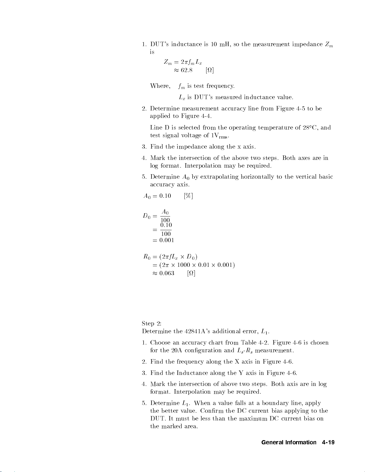
1.
DUT's
is
Zm=
inductance
2
f
mLx
62
:
8
is
[]
10
mH,
so
the
measuremen
t
impedance
Z
m
Where,
2.
Determine
applied
Line D
test
3.
Find
4. Mark
log
format.
5.
Determine
accuracy
A0=
0
D0=
=
=
R0=
=
100
0
0
(2
(2
0
f
m
Lxis DUT's
measuremen
to Figure
is selected
signal
the
the
v
imp
in
A
axis.
:
10
A
0
:
10
100
:
001
2
fL
x
2
1000
:
063 []
is
test
frequency
4-4.
from the
oltage
of
edance
tersection
In
terp
olation
b
y extrap
0
[%]
)
D
0
2
0
:
01
.
measured
t
accuracy
operating
.
1V
rms
along
the
of
the
ab
ma
y
olating horizon
2
0
:
001)
inductance
line
x
axis.
o
v
e
t
w
b
e
required.
from
temp
o
steps.
tally
v
alue.
Figure
erature
Both
to
the
4-5
of
28
axes
v
ertical
to
be
C, and
are
in
basic
Step 2:
Determine
1. Cho ose an accuracy c
the 42841A's additional error,
hart from T
for the 20A conguration and
able 4-2
L
s-Rs
.
L
1
. Figure 4-6 is c
measurement.
hosen
2. Find the frequency along the X axis in Figure 4-6.
3. Find the Inductance along the Y axis in Figure 4-6
.
4. Mark the intersection of abovetwo steps. Both axis are in log
format. Interpolation may be required.
5. Determine
L1. When a value falls at a boundary line, apply
the better value. Conrm the DC current bias applying to the
DUT. It must be less than the maximum DC currentbiason
the marked area.
General Information 4-19
Page 88
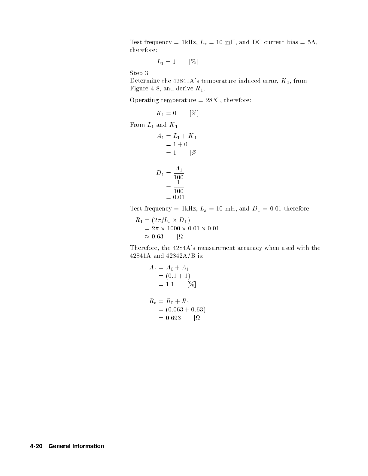
Test
frequency =
therefore:
Step 3:
Determine
Figure
Op
4-8
erating
L1=
1
the 42841A
,
and
deriv
temp
erature
K1=
0
1kHz,
[%]
e
[%]
's
R
L
x
temp
.
1
=
28
=10
erature
C,
mH, and
induced
therefore:
DC curren
error,
tbias
,
K
1
=5A,
from
F
rom
L
1
T
est
frequency
R1=
(2
=
2
0
Therefore,
42841A
and 42842A/B
Ae=
and
A1=
D1=
fL
2
:
63
the
=
=
K
L1+
=
1
=
1
=
=
0
2
x
1000
4284A
A
0
(0
:
1
:
1
1
+
A
100
1
100
:
01
=
[]
+
1
+
0
1
1kHz,
)
D
1
2
A
1
1)
[%]
K
1
[%]
=
L
x
0
:
01
2
0
's
measuremen
is:
=
10
mH,
and
:
01
t
accuracy
D
1
0.01
when
therefore:
used
with
the
4-20 General Information
Re=
=
=
+
R
R
0
1
(0
:
063
+0
0
:
693 []
:
63)
Page 89
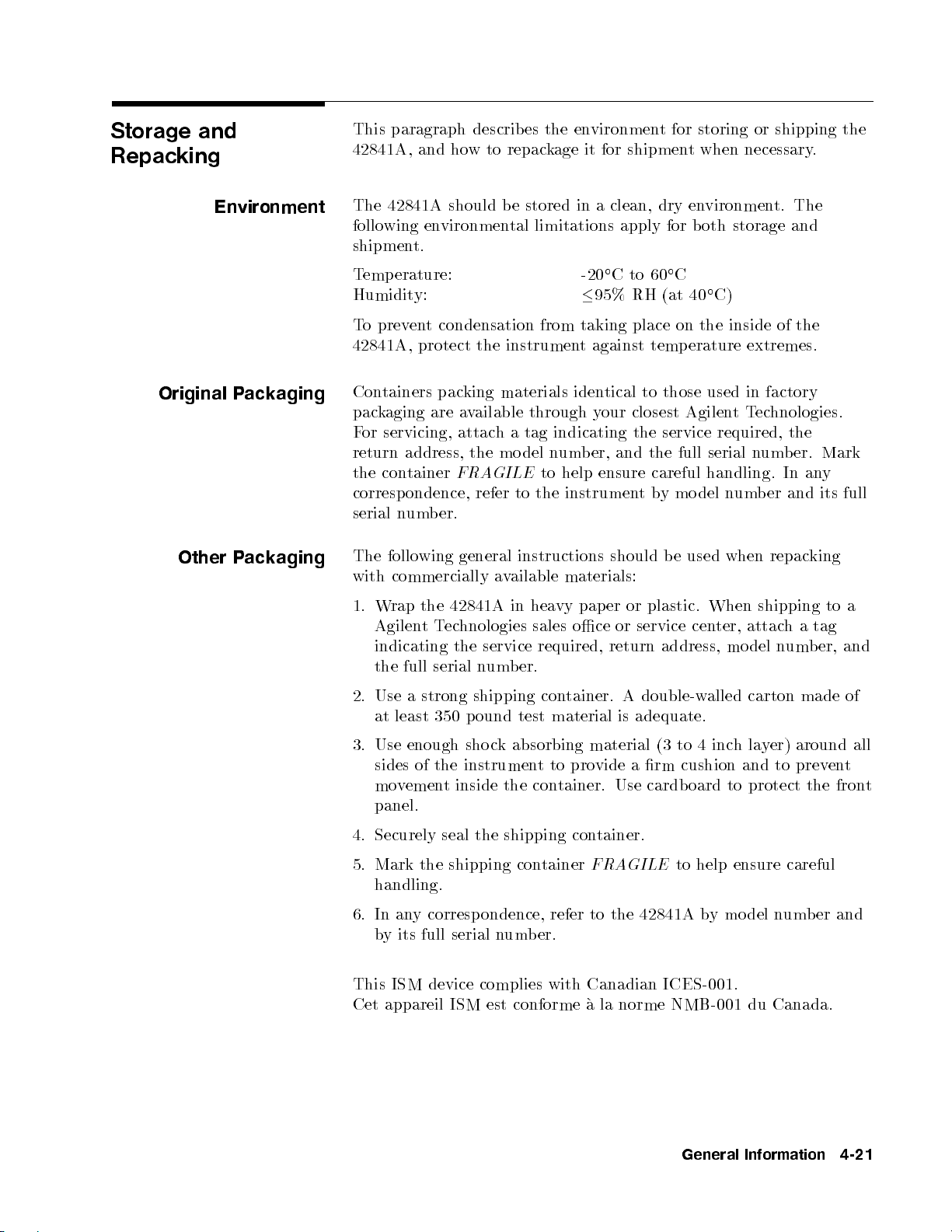
Storage
and
Repacking
Original
Other
Environment
P
ackaging
P
ackaging
This
paragraph
42841A
The
following
shipmen
T
Humidit
T
42841A
Con
pac
F
return
the
,and
42841A
en
t.
emperature:
y:
o
prev
en
t
,
protect
tainers
k
aging are
or
servicing,
pac
address,
con
tainer
how
should
vironmen
condensation
attac
FRA
correspondence,
serial
n
um
b
er.
The
follo
wing
with
commercially
describ
to repac
the
king
av
ailable
h
the
GILE
refer to
general
a
es
the
kage
be
stored in
tal
limitations
from
instrumen
materials
through
a
tag
indicating
mo
del
n
to
the
instructions
v
ailable
en
vironmen
it for
a clean,
C
-20
95%
taking
t
against
iden
tical
y
our
um
b
er,
help
ensure
instrumen
should
materials:
t
shipment
dry en
apply
to 60
RH
place
temp
to
closest
the
and
the
careful
t
b
y
for storing
when
vironment.
for
b
oth
C
on
40
C)
the
(at
erature
those
used in
Agilen
service
full
required,
serial
handling.
mo
del
b
e
used when
or shipping
necessary
storage
inside
extremes.
factory
t
T
ec
n
um
n
um
b
.
The
and
of
the
hnologies.
the
ber.
Mark
In
an
y
er
and
its
repacking
the
full
1. W
rap
the
Agilen
indicating
the
2.
Use
at
3.
Use
sides
mo
t
full
a
strong
least
enough
of
vemen
42841A
T
ec
hnologies
the
serial
350
the
t inside
in
hea
sales
service
n
um
b
er.
shipping con
p
ound
test
sho
c
k
absorbing
instrumen
the con
vy
pap
oce
required,
tainer. A
material
material
t
to
pro
tainer.
er
or
return
is
vide
Use
or
plastic.
service cen
address,
double-w
adequate.
(3
to
a
rm
cushion
cardb
When
alled
4inc
oard
ter,
mo
to
shipping
attac
del
carton
hla
yer)
and
protect
n
to
h
um
a
tag
b
er,
made
around
prev
the
panel.
4.
Securely
5. Mark the shipping con
seal
the
shipping
tainer
con
tainer.
FRAGILE
to help
ensure careful
handling.
6. In an
y correspondence, refer to the 42841A b
by its full serial
number.
ymodeln
umber and
This ISM device complies with Canadian ICES-001.
Cet appareil ISM est conforme a la norme NMB-001 du Canada.
to
en
a
and
of
t
fron
all
t
General Information 4-21
Page 90

Page 91
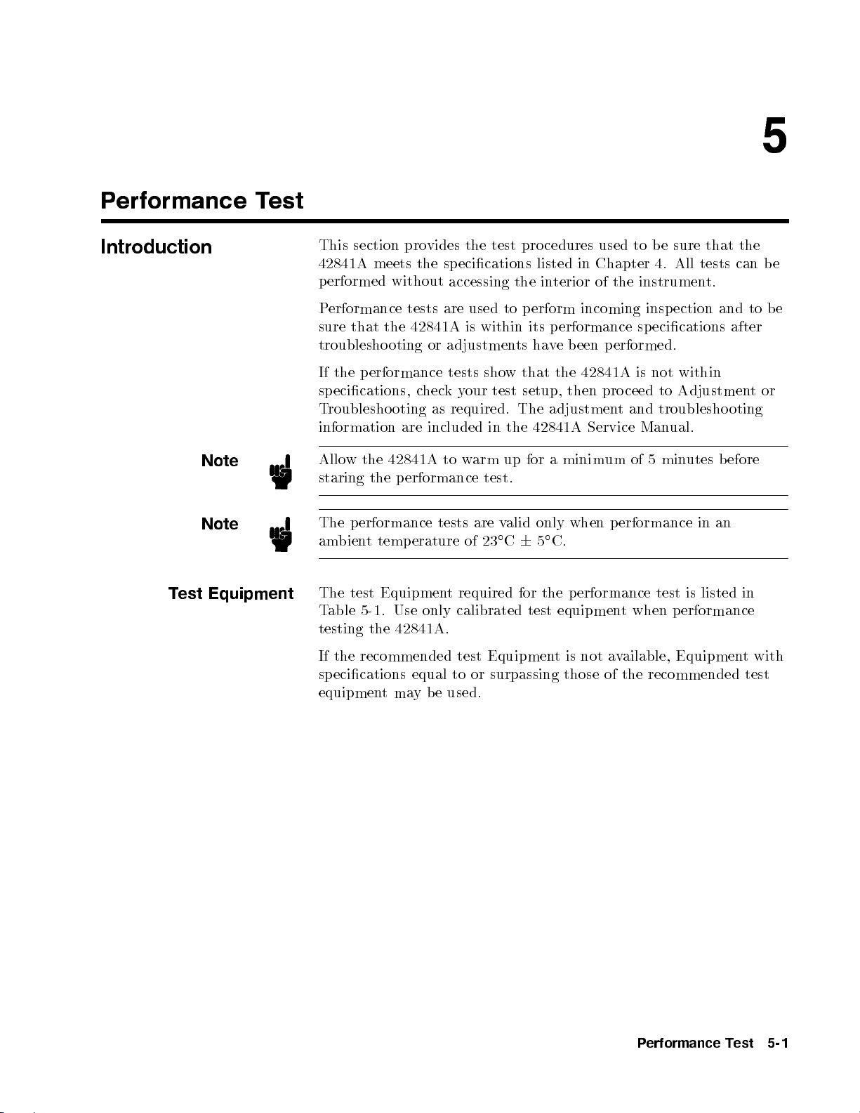
5
Performance
Introduction
Note
Note
T
est
Equipment
T
est
This
section
42841A
p
erformed
P
erformance
sure
that
meets
the
troublesho
If
the
performance
sp
ecications,
T
roublesho
information
Allo
w
the
staring
The
am
The
T
testing
p
erformance
bien
test
able
the
t
temp
Equipmen
5-1.
the
pro
vides
the sp
without
tests
42841A
oting or
c
hec
oting
as
are
included
42841A
p
erformance
erature
Use
only
42841A
the
test
ecications listed
accessing
are
used
is
the
to
within
adjustments
tests sho
k
y
required.
to
w
our
arm
test
in
w
The
the
up for
test.
tests
are
v
alid
C
23
6
for
of
t
required
calibrated test
.
pro
cedures
in
terior
p
erform
its
p
erformance
hav
e
that
the
setup,
adjustmen
42841A
a minim
only when
C.
5
the
equipment
used
in Chapter
of
the
incoming
b
een
p
erformed.
42841A
then
pro
t
Service
um of
p
erformance
p
erformance
to
b
e sure
4. All
instrumen
insp
ection
sp
ecications after
is
not
within
ceed
to
Adjustmen
and
troublesho
Man
ual.
5min
utes
test
is
when
p
erformance
that the
tests
t.
and
oting
b
efore
in
an
listed
can
in
to
t
b
or
e
b
e
If
the
recommended
sp
ecications
equipmen
tma
equal
yb
e
test
to
or
used.
Equipmen
surpassing
t
is
those
not
av
ailable, Equipmen
of
the
recommended
Performance Test 5-1
t with
test
Page 92
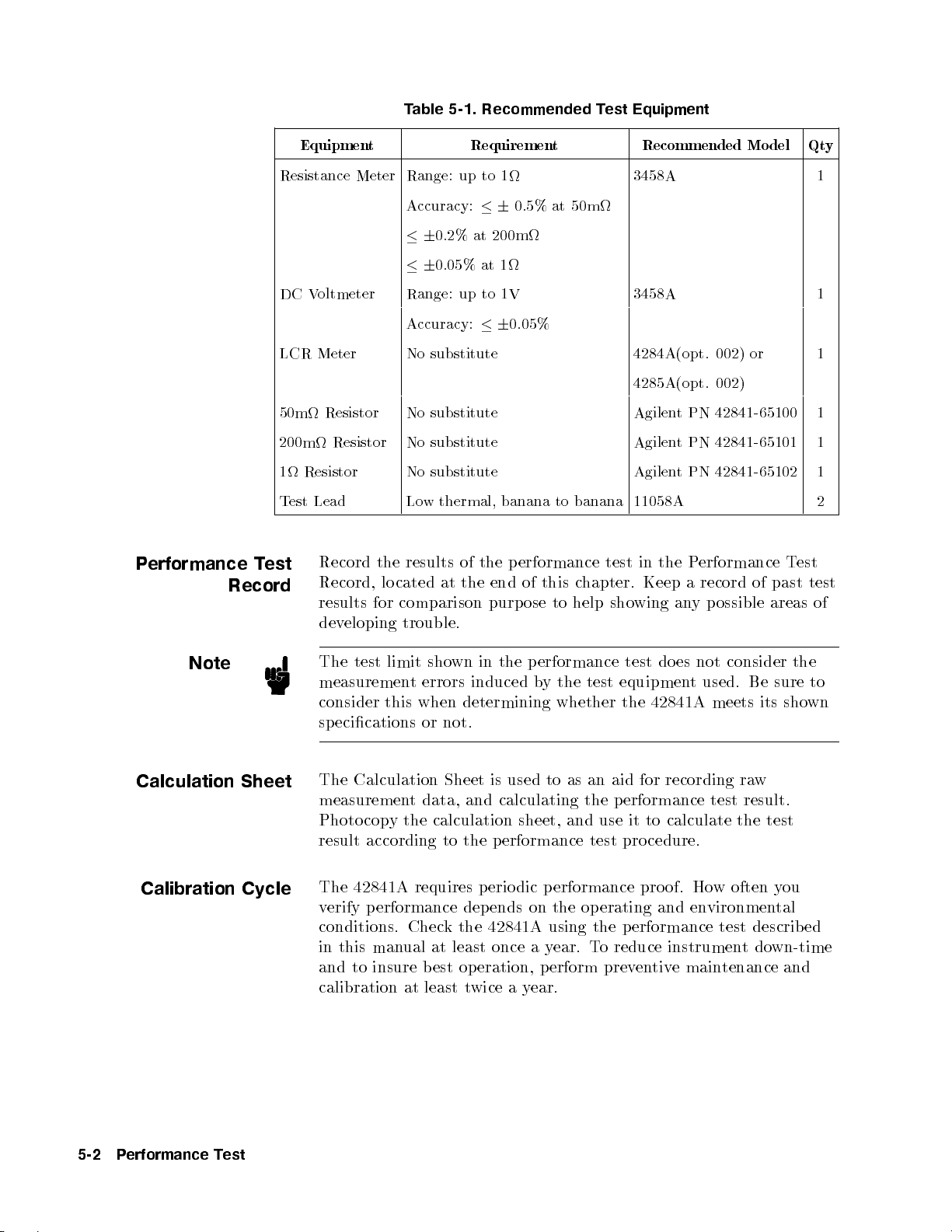
Table
5-1. Recommended
Test
Equipment
P
erformance
T
est
Record
Equipmen
Resistance
DC
Voltmeter
LCR
Meter
50m
Resistor
200m
1
T
Resistor
est
Lead
Resistor
Record
Record,
results
dev
t
Meter
the
lo
for
eloping
Range:
up
Accuracy:
6
0.2%
6
0.05%
Range:
up to
Accuracy:
No
substitute
No
substitute
No
substitute
No
substitute
Lo
w
thermal,
results
cated
at
of
the
comparison
trouble.
Requiremen
to
1
6
0.5% at
at
200m
at
1
1V
6
0.05%
banana
the
p
erformance
end
of
purpose
t
to
this
to
50m
banana
c
hapter.
help
Recommended
Model
3458A 1
3458A 1
4284A(opt.
4285A(opt.
Agilen
Agilen
Agilen
002)
or
002)
t
PN 42841-65100
t
PN
42841-65101
t
PN
42841-65102
11058A 2
test
in
the
P
erformance
Keep
a
sho
wing
an
record
y
p
ossible
of
T
past
areas
est
Qt
1
1
1
1
test
of
y
Note
Calculation
Sheet
Calibration Cycle
The
test limit
measuremen
consider
sp
ecications or
The
Calculation
measuremen
Photo
copy
result
according
shown
t
errors
this
when
determining
not.
Sheet
t
data,
the calculation
to
in
the
induced
is
and
calculating
the
p
p
erformance
b
y
the
whether
used to
sheet,
as an
and
erformance
test
the
test
aid for
p
use
test
do
es
equipment
the
42841A
recording ra
erformance
it
to
calculate
pro
cedure.
not
The 42841A requires p eriodic p erformance proof. Ho
verify performance depends on the op erating and
conditions.
in this man
and to insure best operation, perform prev
calibration at least t
Check the 42841A using the p erformance test described
ual at least once a y
ear. T
o reduce instrumen
entivemain
wice a y
ear.
environmental
consider
used. Be
meets
its
w
test
result.
the
w often y
t
down-time
tenance and
sure
test
the
sho
ou
to
wn
5-2 Performance Test
Page 93
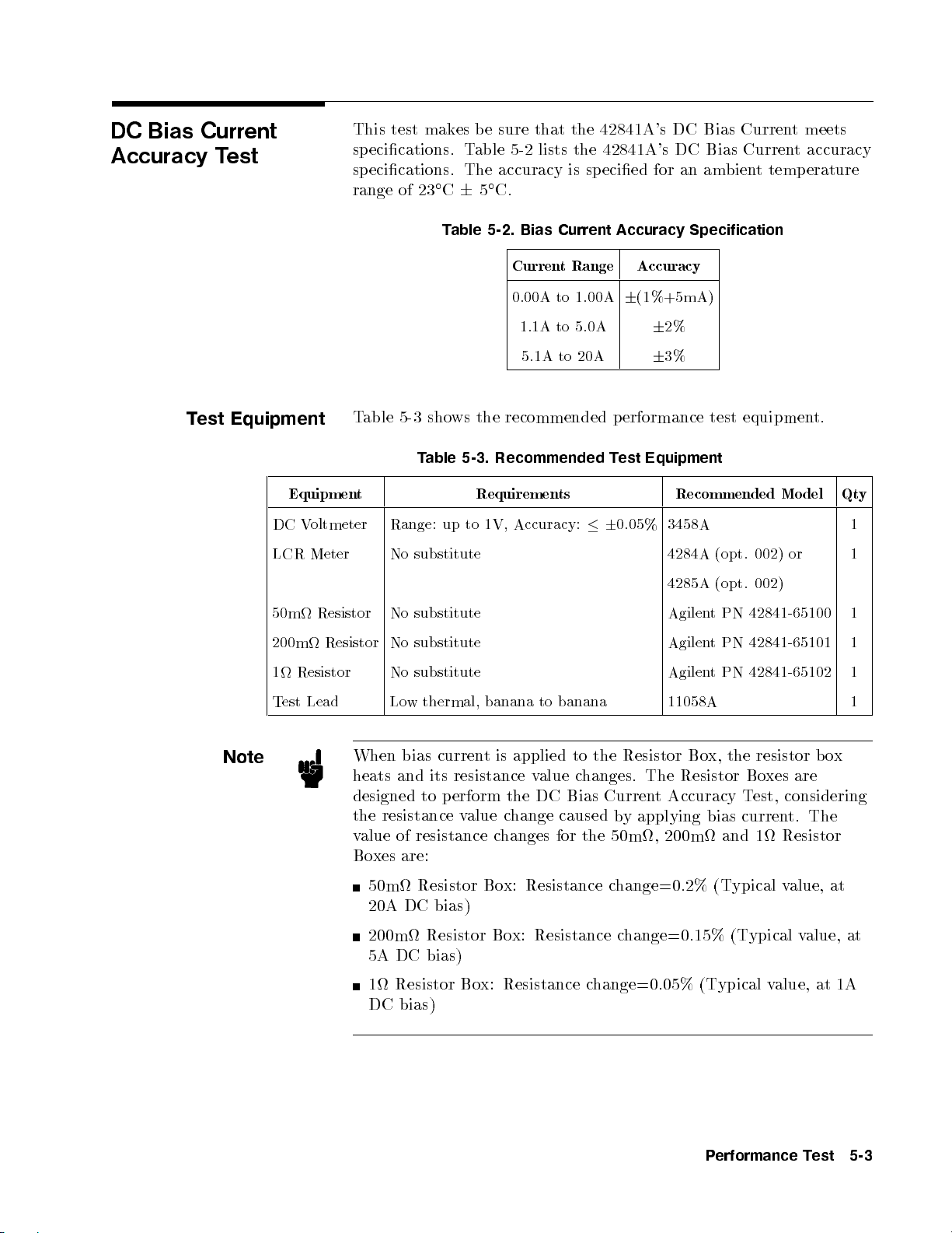
DC
Bias
Accuracy
Current
Test
This
test
mak
sp
ecications. T
specications.
of
23
C
range
T
es
b
e
sure
able 5-2
The accuracy
C.
6
5
able
5-2.
Bias
that
the 42841A
lists the
is
Current
42841A's
sp
ecied
Accuracy
's DC
DC Bias
for
an
Specification
Bias Curren
Current
am
bien
t
temp
t meets
accuracy
erature
T
est
Equipment
Equipment Requirements Recommended Mo
DC
V
oltmeter
LCR
Meter
50m
200m
1
Resistor
T
est
Lead
T
Resistor
Resistor
able
5-3
T
Range:
No
substitute
No
substitute
No
substitute
No
substitute
Lo
w
thermal,
sho
able
up
ws the
5-3.
Recommended
to
1V,
banana
Curren
0.00A
1.1A
5.1A
t Range
to
1.00A
to 5.0A
to
20A
recommended p
Accuracy:
to
banana
6
Accuracy
6
(1%+5mA)
6
2%
6
3%
erformance
T
est
Equipment
0.05%
test
equipmen
del
t.
Qty
3458A 1
4284A
(opt.
002)
or
4285A
(opt.
002)
Agilen
t
PN
42841-65100
Agilen
t
PN
42841-65101
Agilen
tPN
42841-65102
11058A 1
1
1
1
1
Note
When
heats and
designed
the
v
Bo
resistance
alue
of
xes are:
bias
curren
its resistance
to
p
erform
resistance
v
alue
50m Resistor Bo
20A DC bias)
200m Resistor Bo
5A DC bias)
1 Resistor Bo
DC bias)
t
is
applied
the
c
hange
c
hanges
value
DC
to
changes.
Bias
caused
for the
x: Resistance c
x: Resistance c
x: Resistance c
the
Resistor
Current
b
y
applying
50m,
Bo
The
Resistor
Accuracy T
200m
hange=0.2% (T
hange=0.15% (T
hange=0.05% (T
Performance Test 5-3
x,
the
resistor
Bo
est, considering
bias
curren
and
1
ypical v
ypical v
ypical v
b
xes
are
t. The
Resistor
alue, at
alue, at
alue, at 1A
o
x
Page 94
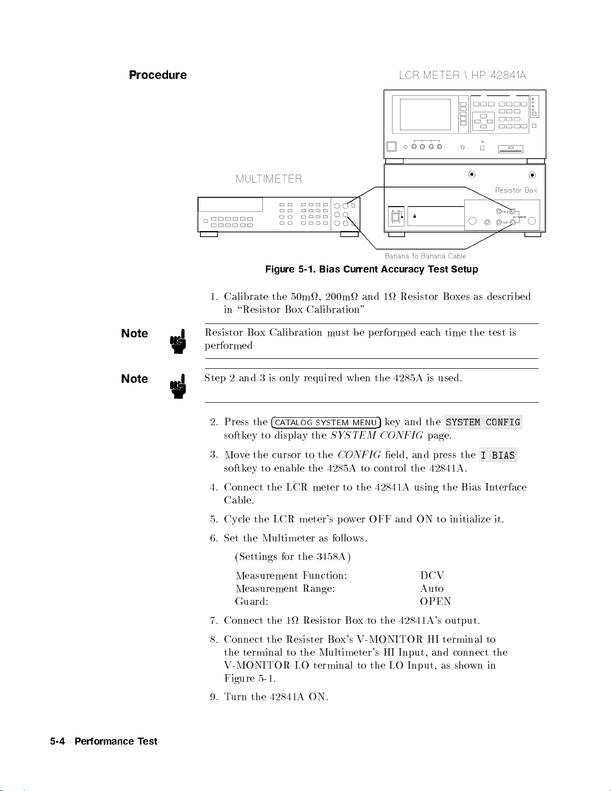
Procedure
Note
Note
1.
Calibrate
in
Resistor
p
erformed
Step
2
2.
Press
softk
3.
Mo
softk
4.
Connect
Cable.
5.
Cycle the
6. Set
(Settings for the 3458A)
Figure
the
\Resistor Bo
Bo
x
Calibration
and
3
is
only
the
4
CA
T
ey
to
displa
ve
the cursor
ey to
enable the
the
LCR
LCR
the
Multimeter
5-1. Bias
50m,
200m
x
Calibration"
required
ALOG
SYSTEM
y
the
to
the
meter
meter's
as
Current
m
ust
b
e
when
MENU
SYSTEM
CONFIG
4285A
to
p
o
follo
w
ws.
to
the 42841A
er
Accuracy
and
1
p
erformed
the
5
k
CONFIG
con
OFF
Resistor
4285A
ey
eld,
trol
and
T
eac
is
and
the
page.
and
the
42841A
using the
ON
est
Bo
h
time
used.
N
N
N
SYSTEM
press
to
Setup
xes
as
the
N
N
N
N
N
N
NN
N
N
N
N
N
N
N
N
N
N
N
N
N
I
the
.
Bias In
initialize
describ
test
N
N
N
N
N
N
N
N
N
N
N
N
N
CONFIG
N
N
N
N
N
N
N
N
N
N
NN
NN
BIAS
terface
it.
ed
is
NN
N
N
N
N
N
N
N
N
5-4 Performance Test
MeasurementF
Measurement
unction: DCV
Range: Auto
Guard: OPEN
7. Connect the 1 Resistor Bo
x
to the 42841A
's output.
8. Connect the Resister Box's V-MONITOR HI terminal to
the terminal to the Multimeter's HI Input, and connect the
V-MONITOR LO terminal to the LO Input, as shown in
Figure 5-1.
9. Turn the 42841A ON.
Page 95
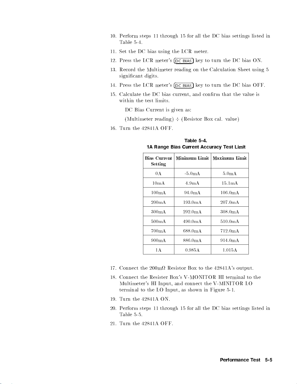
10.
P
erform
T
able 5-4.
steps
11
through
15
for
all
the
DC bias
settings listed
in
11. Set
12.
Press
13.
Record the
signican
14.
Press
15.
Calculate the
within
DC
(Multimeter
16.
T
urn
the DC
the
t
the
the
Bias
the
42841A
bias using
LCR
meter's
Multimeter reading
the
4
DC
LCR
BIAS
meter.
5
k
ey
on the
to
turn the
Calculation
digits.
5
k
ey
and
to
turn
conrm
Bo
x
LCR
test
Curren
meter's
DC bias
limits.
t
is
reading)
4
DC
curren
giv
en as:
4
BIAS
t,
(Resistor
OFF.
T
able
5-4.
1A
Range
Bias Curren
Bias
Minimum
t
Current
Accuracy
Limit
Maximum
Setting
0A -5.0mA 5.0mA
10mA 4.9mA 15.1mA
cal.
the
that
v
alue)
T
est
DC bias
Sheet
DC bias
the
v
alue
Limit
Limit
ON.
using
OFF.
is
5
100mA 94.0mA 106.0mA
200mA 193.0mA 207.0mA
300mA 292.0mA 308.0mA
500mA 490.0mA 510.0mA
700mA 688.0mA 712.0mA
900mA 886.0mA 914.0mA
1A 0.985A 1.015A
17. Connect the 200m Resistor Bo
18. Connect the Resister Bo
x's V-MONITOR HI
x to the 42841A's output.
terminal to the
Multimeter's HI Input, and connect the V-MINITOR LO
terminal to the LO Input, as sho
19. T
urn
the 42841A ON.
20. P
erform steps 11 through 15 for all the DC bias settings listed in
wn in Figure 5-1
.
Table 5-5.
21. Turn the 42841A OFF.
Performance Test 5-5
Page 96
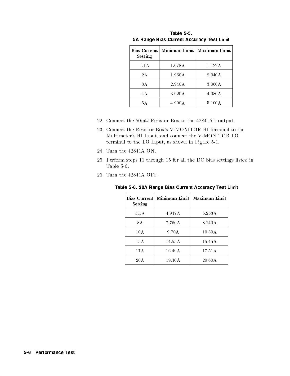
5A
Range
Bias
Table
Current
5-5.
Accuracy
T
est
Limit
22.
Connect
23.
Connect
Multimeter's
terminal to
24.
T
urn
25.
P
erform
T
able
26.
T
urn
Bias Curren
the
the
the
the 42841A
steps
5-6
.
the 42841A
T
able
5-6.
Minimum
t
Limit
Maximum
Setting
1.1A 1.078A 1.122A
2A 1.960A 2.040A
3A 2.940A 3.060A
4A 3.920A 4.080A
5A 4.900A 5.100A
50m
Resistor
HI
Resistor
Input,
LO
Bo
and
Input,
Bo
x
to
x's
V-MONITOR
connect
as
sho
wn
the
42841A
HI
the V-MONITOR
in
Figure
ON.
11
through
15
for
all
the
DC
bias
OFF.
20A
Range
Bias
Current
Accuracy
Limit
's
output.
terminal
to the
LO
5-1
.
settings listed
T
est
Limit
in
Bias
Curren
Minim
t
um
Limit
Maxim
Setting
5.1A 4.947A 5.253A
8A 7.760A 8.240A
10A 9.70A 10.30A
15A 14.55A 15.45A
17A 16.49A 17.51A
20A 19.40A 20.60A
um
Limit
5-6 Performance Test
Page 97
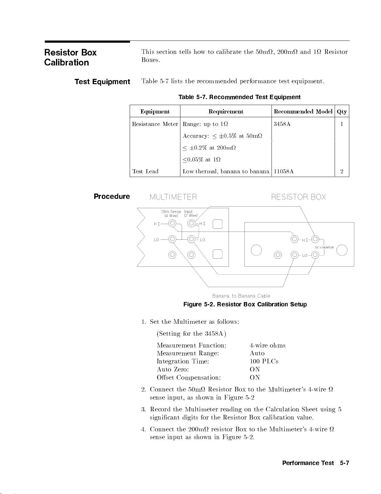
Resistor
Bo
Calibration
T
est Equipment
This
Bo
xes.
Table
section
5-7 lists
x
tells
ho
w
to
calibrate
the recommended
T
able 5-7.
Recommended T
the
50m, 200m
p
erformance
est Equipment
test
and 1
equipmen
Resistor
t.
Procedure
Equipmen
Resistance
T
est
Lead
t
Meter
Range:
up
Accuracy:
6
0.2%
0.05%
Lo
w
thermal,
Requiremen
to
1
6
0.5%
at 200m
at
1
banana
t
at 50m
to
banana
Recommended
Mo
del
Qt
3458A 1
11058A 2
y
Figure
1.
Set
the
Multimeter
(Setting
for the
MeasurementF
Measurement Range:
Integration Time:
Auto Zero:
Oset Compensation:
2. Connect the 50m Resistor Bo
sense input, as sho
5-2.
Resistor
as
follo
ws:
Bo
x
Calibration
3458A)
unction: 4-wire ohms
Auto
100 PLCs
ON
ON
x to the Multimeter's 4-wire
wn
in Figure 5-2
Setup
3. Record the Multimeter reading on the Calculation Sheet using 5
signicant digits for the Resistor Box calibration value.
4. Connect the 200m resistor Box to the Multimeter's 4-wire
sense input as shown in Figure 5-2.
Performance Test 5-7
Page 98

5.
Record the
signicant
6.
Connect
input
Multimeter reading
digits for
the
1
Resistor
as sho
wn in
the
Resistor
Bo
Figure 5-2
on the
Bo
x
calibration
xto
the Multimeter's
.
Calculation Sheet
v
alue.
4-wire
using 5
sense
7. Record
signican
the
Multimeter
t
digits
for
the
reading
Resistor
on
Bo
the
x
Calculation
Calibration v
Sheet
alue.
using
5
5-8 Performance Test
Page 99
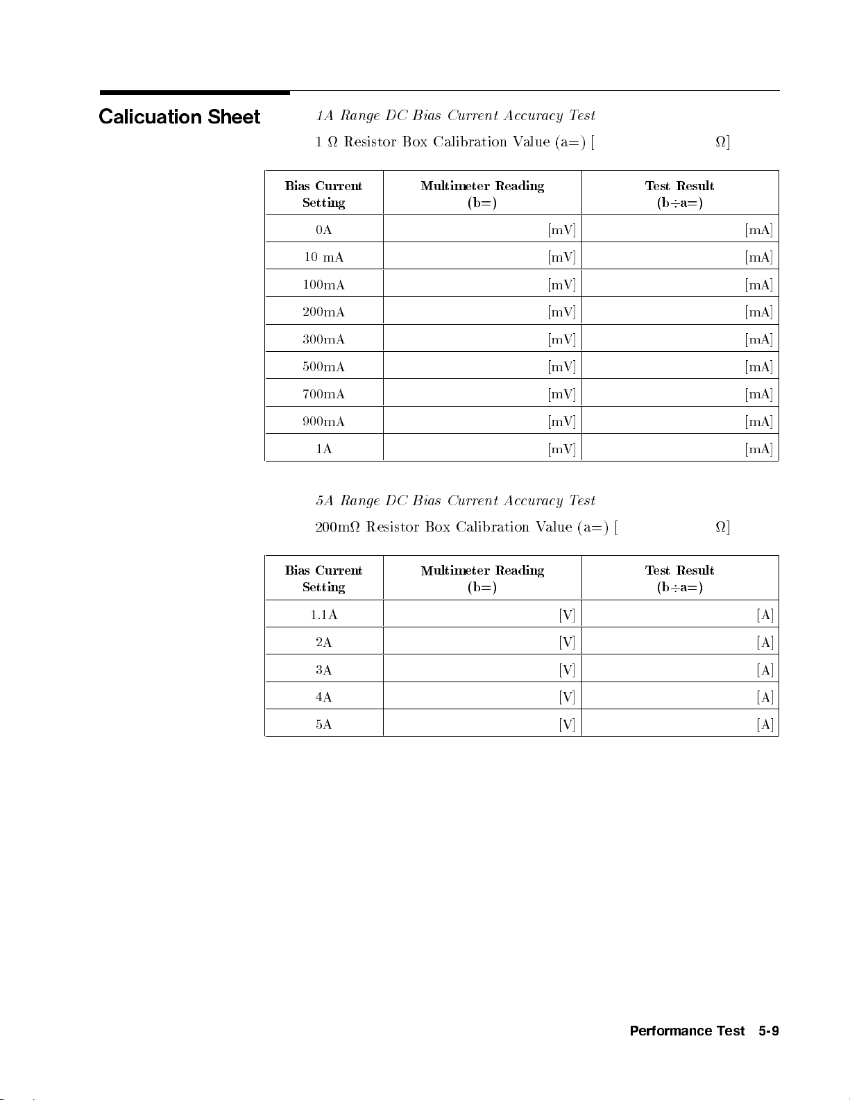
Calicuation
Sheet
1A
R
ange
1
Resistor
DC
Bias
Curr
Box
Calibration V
ent
A
ccur
alue (a=)
acy T
est
[ ]
Bias Curren
Setting
t
Multimeter Reading
(b=)
Test
(b
Result
4
a=)
0A [mV] [mA]
10
mA
[mV] [mA]
100mA [mV] [mA]
200mA [mV] [mA]
300mA [mV] [mA]
500mA [mV] [mA]
700mA [mV] [mA]
900mA [mV] [mA]
1A [mV] [mA]
5A
R
ange
DC
Bias
Curr
ent
A
c
cur
acy
T
est
Bias
200m
Curren
Setting
Resistor
t
Bo
x
Calibration
Multimeter
(b=)
Reading
Value
(a=)
[
T
est
(b
4
]
Result
a=)
1.1A [V] [A]
2A [V] [A]
3A [V] [A]
4A [V] [A]
5A [V] [A]
Performance Test 5-9
Page 100
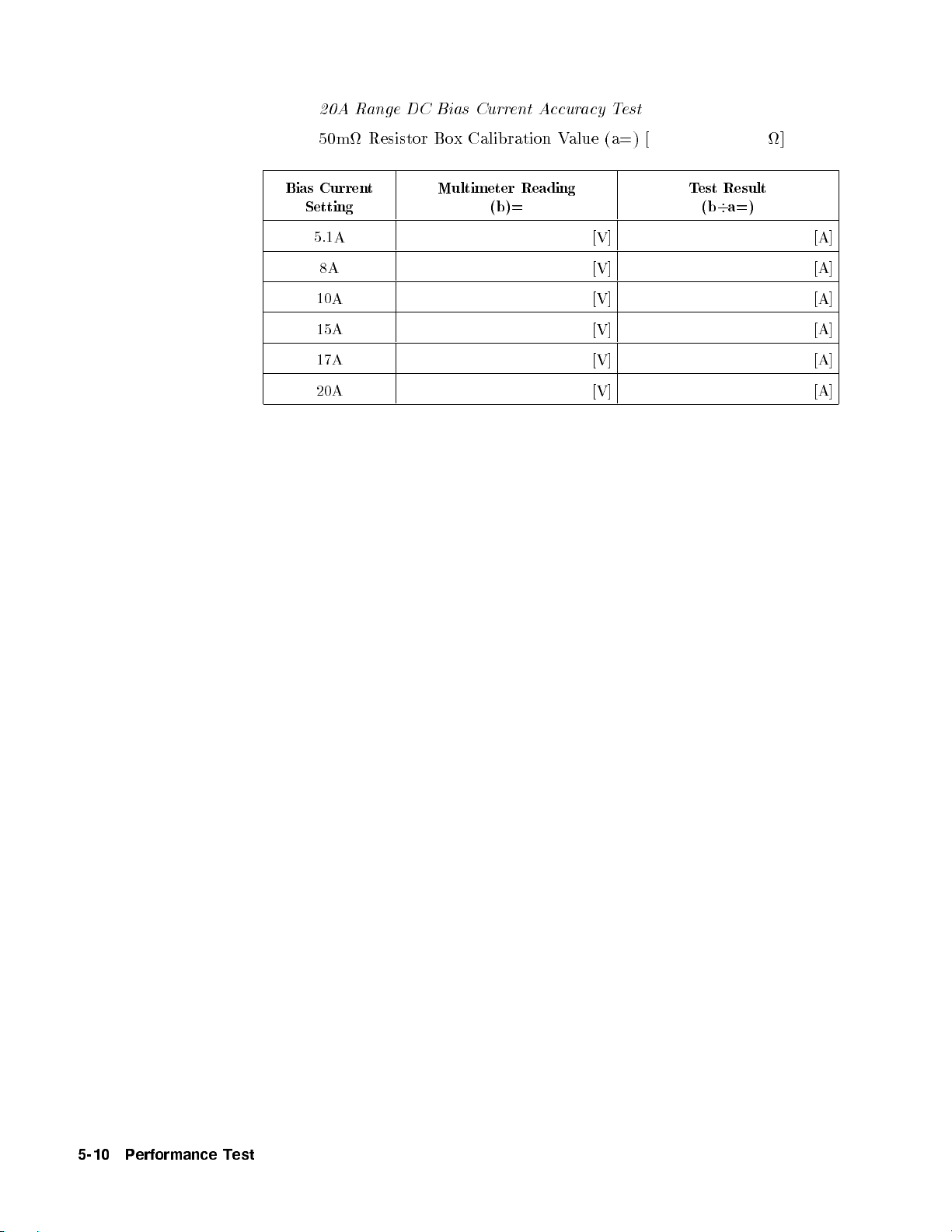
20A R
ange DC
Bias Curr
ent A
ccur
acy
T
est
Bias
50m
Curren
Setting
Resistor
t
Bo
x
Calibration
Multimeter
(b)=
V
Reading
alue
(a=)
[ ]
T
est
(b
Result
4
a=)
5.1A [V] [A]
8A [V] [A]
10A [V] [A]
15A [V] [A]
17A [V] [A]
20A [V] [A]
5-10 Performance Test
 Loading...