

Page 1

1680A/AD-Series and 1690A/AD-Series
Logic Analyzers
The Following manual is a copy of the 1680/90 logic analyzer online help system.
Information covering the operation of any "Add-in" tools listed in the Tools Menu of
the product is covered in separate documentation for those tools.
1680A/AD-Series
1690A/AD-Series
1
Page 2

2
Page 3

Table of Contents
TUTORIAL - GETTING TO KNOW YOUR LOGIC ANALYZER ....... 17
Logic analyzer basics .........................................................................19
When should I use an oscilloscope ..............................................................19
When should I use a logic analyzer .............................................................20
What is a Logic Analyzer ............................................................................21
What is a Logic Analyzer ............................................................................21
What is a timing analyzer ....................................................................................21
What is a state analyzer ...................................................................................... 21
Clocking data in the timing analyzer .....................................................................22
Sampling in the timing analyzer ...........................................................................23
Sampling accuracy ..........................................................................................23
Triggering the timing analyzer.............................................................................. 25
Pattern Trigger................................................................................................25
Edge Trigger ...................................................................................................25
Clocking data in the state analyzer .......................................................................27
Sampling in the state analyzer .............................................................................28
Triggering the state analyzer ...............................................................................29
Probing options.........................................................................................31
General Purpose Probing .....................................................................................31
Adaptor to board connectors ................................................................................ 33
Analysis Probes .................................................................................................. 33
Measurement overview ......................................................................34
Turning on the logic analyzer......................................................................34
Connecting to the target system .................................................................35
Credit card demo board ............................................................................. 36
Setting up bus/signal names ......................................................................37
Delete bus/signal names .....................................................................................37
Add new bus/signal name .................................................................................... 37
Map signals into the analyzer ...............................................................................38
Setting the acquisition mode ......................................................................39
Setting up a simple trigger .........................................................................40
Open the tutorial configuration file ..............................................................41
Load the configuration file ...................................................................................41
View the data..................................................................................................... 41
Using markers ..........................................................................................42
To create a marker ............................................................................................. 42
To place a marker in data ....................................................................................42
Go To a marker in data .......................................................................................42
Zooming in on the data .............................................................................43
Expand a bus .....................................................................................................43
3
Page 4

Change the scale ................................................................................................43
Time saving tasks .............................................................................44
Loading and saving configuration files .........................................................44
Saving and recalling trigger setups.............................................................. 45
To recall a trigger setup ......................................................................................45
Quick marker measurements ......................................................................46
Searching data .........................................................................................47
Toolbars, tooltips and mouse shortcuts ........................................................48
Toolbars ............................................................................................................48
Mouse shortcuts ................................................................................................. 48
Tooltips .............................................................................................................48
MEASUREMENT EXAMPLES...................................................... 49
Making a timing analyzer measurement ...............................................50
Bus and signal setup ...........................................................................................50
Acquisition mode setup ....................................................................................... 50
Trigger setup ..................................................................................................... 50
Run the measurement.........................................................................................50
Making a state analyzer measurement .................................................51
Bus and signal setup ...........................................................................................51
Acquisition mode setup ....................................................................................... 51
Trigger setup ..................................................................................................... 51
Run the measurement.........................................................................................51
External Triggering ............................................................................52
Trigger signal characteristics................................................................................ 52
To trigger other instruments - Trigger Out ...................................................52
To trigger analyzer from another instrument - Trigger In ...............................52
Making marker measurements ............................................................54
To create a new interval measurement ........................................................55
To create a new value at measurement .......................................................56
TRIGGER FUNCTIONS ............................................................. 57
Timing mode trigger functions ............................................................57
Edge .......................................................................................................60
"N" number of edges .................................................................................61
Edge followed by edge ...............................................................................62
Edge followed by pattern ...........................................................................63
Edges too far apart ...................................................................................64
Pattern .................................................................................................... 65
4
Page 5

Edge and Pattern ......................................................................................66
Pattern present for > "T" time ....................................................................67
Pattern present for < "T" time ....................................................................68
Pattern absent for > "T" time .....................................................................69
Pattern absent for < "T" time .....................................................................70
Pattern too late after edge .........................................................................71
Pattern "AND" Pattern (timing) ...................................................................72
Pattern "OR" Pattern (timing) ..................................................................... 73
Find anything "N" times (timing).................................................................74
Width violation on pattern or pulse..............................................................75
Wait "T" seconds.......................................................................................76
Wait for external arm (timing) ....................................................................77
Run until user stop (timing) .......................................................................78
Reset and start timer (timing) ....................................................................79
Advanced If/Then (timing) .........................................................................80
Advanced 2-Way Branch (timing)................................................................81
Advanced 3-Way Branch (timing)................................................................82
Advanced 4-Way Branch (timing)................................................................83
State mode trigger functions ..............................................................84
Pattern "N" times ......................................................................................85
"N" consecutive samples with Pattern1 ........................................................86
Pattern1 followed by Pattern2.....................................................................87
Pattern1 immediately followed by Pattern2 ..................................................88
Pattern1 followed by Pattern2 before Pattern3 ..............................................89
Too few states between Pattern1 and Pattern2 .............................................90
Too many states between Pattern1 and Pattern2 ..........................................91
Pattern2 occurring too soon after Pattern1 ...................................................92
Pattern2 occurring too late after Pattern1 ....................................................93
Find anything "N" times (state)................................................................... 94
Run until user stop (state) .........................................................................95
Reset and start timer (state) ......................................................................96
Wait for external arm (state) ...................................................................... 97
Wait "N" external clock states.....................................................................98
Pattern "AND" Pattern (state) .....................................................................99
Pattern "OR" Pattern (state) ..................................................................... 100
Advanced If/Then (state) ......................................................................... 101
Advanced 2-Way Branch (state) ............................................................... 102
Advanced 3-Way Branch (state) ............................................................... 103
Advanced 4-Way Branch (state) ............................................................... 104
5
Page 6

TASK GUIDE.......................................................................... 105
Waveform Window Tasks ................................................................. 106
Bus/Signal configuration .......................................................................... 106
To reposition bus/signal names .......................................................................... 107
Simple Trigger ........................................................................................ 107
Marker display bar .................................................................................. 107
Waveform display area ............................................................................ 107
Working with Markers.............................................................................. 109
To set waveform window properties ..........................................................110
To set window properties................................................................................... 110
To set row properties ........................................................................................ 110
To set background color ................................................................................. 110
To set font size ............................................................................................. 110
To set an overlay color................................................................................... 111
To show activity indicators.............................................................................. 111
To show tool tip - values ................................................................................111
To show tool tip - transition width ................................................................ 111
To set markers - snap to edge ........................................................................ 111
To set markers - move edge on screen ......................................................... 111
To set markers - place on edge ....................................................................... 112
To select the Bus/Signal................................................................................. 112
To set data color ........................................................................................... 112
To set row height .......................................................................................... 112
To set numeric base ...................................................................................... 112
To show data values ......................................................................................113
To show soft glitch ........................................................................................ 113
To set bus options ......................................................................................... 113
To set waveform style - Bus ........................................................................ 113
To set waveform style - Magnitude ............................................................... 113
To expand into signals ................................................................................ 114
Change delay ......................................................................................... 115
Change scale (time/division) ....................................................................116
Change the scale .............................................................................................. 116
Draw a rectangle in the data.............................................................................. 116
To overlay bus/signals ............................................................................. 118
To group signals into a bus ...................................................................... 119
To add or delete display windows.............................................................. 120
To add a new display windows ........................................................................... 120
To delete display windows ................................................................................. 120
Turning window tabs on/off ...................................................................... 121
Set quick trigger with rectangle ................................................................122
General guidelines: ................................................................................. 122
Specific guidelines to the listing display: ....................................................122
Specific guidelines to the waveform display:............................................... 122
6
Page 7

To draw the rectangle .......................................................................................122
Tool Tips................................................................................................ 124
To add user comments ............................................................................ 125
To edit symbols for a bus/signal ............................................................... 126
To add a symbol............................................................................................... 126
To edit a symbol............................................................................................... 126
To delete a symbol ........................................................................................... 126
To save symbols............................................................................................... 126
Listing Display Window ....................................................................128
Column configuration .............................................................................. 128
To reposition bus/signal names .......................................................................... 129
Simple Trigger ........................................................................................ 129
Marker display bar .................................................................................. 129
Listing display area ................................................................................. 129
Column configuration .............................................................................. 130
Insert Column Before ........................................................................................ 130
Insert Column After ..........................................................................................130
Delete Column ................................................................................................. 130
Assign Channels ............................................................................................... 130
Rename .......................................................................................................... 130
Symbols .......................................................................................................... 130
Display............................................................................................................ 130
Properties........................................................................................................ 130
To set listing window properties................................................................ 131
To set window properties................................................................................... 131
To set column properties ................................................................................... 131
To set background color ................................................................................. 131
To set font size ............................................................................................. 131
Column display options .................................................................................. 131
Display activity indicators............................................................................ 131
Display column base ................................................................................... 132
Display simple trigger ................................................................................. 132
To show center rectangle ............................................................................... 132
To select the Bus/Signal name ........................................................................ 132
To set data color ........................................................................................... 132
To set column width ...................................................................................... 133
To set column alignment ................................................................................ 133
To set numeric base ...................................................................................... 133
To set marker relative.................................................................................... 133
To display symbols.................................................................................. 134
Example .......................................................................................................... 135
7
Page 8

Buses/Signals Setup ........................................................................ 136
Read only options ................................................................................... 136
To add a new bus or signal....................................................................... 138
To delete a bus or signal.......................................................................... 139
To delete an individual bus or signal ................................................................... 139
To delete all buses and signals ........................................................................... 139
To rename a bus or signal ........................................................................ 140
To assign channels.................................................................................. 141
To set thresholds .................................................................................... 142
To set numeric base ................................................................................ 143
To set polarity ........................................................................................ 145
To set setup/hold .................................................................................... 146
To add a folder ....................................................................................... 148
To alias a bus/signal name ....................................................................... 149
Sampling Setup Tasks ..................................................................... 150
State - Synchronous Sampling mode......................................................... 150
Timing - Asynchronous Sampling mode ..................................................... 150
To set the acquisition mode...................................................................... 152
To select the timing analyzer ............................................................................. 152
To select the state analyzer ............................................................................... 152
To set acquisition depth ........................................................................... 153
To set the trigger position ........................................................................ 154
To select the state clock type ................................................................... 155
Master ............................................................................................................ 155
Master/Slave ................................................................................................... 155
Demultiplex ..................................................................................................... 156
To set the state clock qualifier .................................................................. 157
To set up advanced clocking..................................................................... 158
To set the sampling period ....................................................................... 159
To set sampling options ........................................................................... 160
Transitional timing .................................................................................. 161
More on storing transitions ................................................................................ 161
Minimum transitions stored ............................................................................ 161
Maximum transitions stored............................................................................ 161
Transitional timing considerations....................................................................... 161
Data storage................................................................................................. 161
Sequence level branching ............................................................................... 162
Global counters ............................................................................................. 162
Storing Time Tags ......................................................................................... 162
Increasing Duration of Storage........................................................................ 162
Invalid Data.................................................................................................. 162
Trigger Position ............................................................................................. 162
8
Page 9

Triggering ......................................................................................163
Simple Trigger Tasks ............................................................................... 164
Simple Trigger ........................................................................................ 164
To set bus pattern triggers ................................................................................ 166
Operators ..................................................................................................... 166
To set signal trigger options............................................................................... 167
Options ........................................................................................................ 167
To triggering on a glitch .............................................................................. 167
Advanced Trigger Tasks ........................................................................... 168
Advanced Trigger Dialog .......................................................................... 168
To build a trigger sequence................................................................................ 169
Trigger steps ................................................................................................ 169
To set store qualification ................................................................................... 170
Default storage ............................................................................................. 170
Sequence step storage ................................................................................... 170
Storage interaction ........................................................................................ 171
How to read event and action statements ............................................................ 173
To insert events and actions ..............................................................................174
To negate a function statement .......................................................................... 176
To modify trigger step display ............................................................................ 177
ANDing and ORing Event statements .................................................................. 179
To store a trigger ............................................................................................. 180
Most recently used trigger list ......................................................................... 180
Stored favorite triggers list ............................................................................. 180
Recall Trigger Dialog ......................................................................................... 181
To recall a trigger .......................................................................................... 181
To configure a counter ...................................................................................... 182
To insert a counter event ............................................................................... 182
To insert a counter action............................................................................... 182
See Also....................................................................................................... 183
To configure a timer ......................................................................................... 184
Model .......................................................................................................... 184
Timing Acquisition Mode................................................................................. 184
State Acquisition Mode................................................................................... 184
To insert a timer check event............................................................................. 184
To insert a timer start action.............................................................................. 185
9
Page 10

Marker Tasks .................................................................................. 187
To create new markers ............................................................................ 187
Using abbreviated names ............................................................................... 187
To place markers in data ......................................................................... 188
Place marker at center screen ............................................................................ 188
Place marker at mouse cursor ............................................................................ 188
Go To Markers ........................................................................................ 189
To center the display about a marker ........................................................190
To delete a marker.................................................................................. 191
To rename a marker................................................................................ 192
To send a marker to the back ................................................................... 193
To set marker properties.......................................................................... 194
To rename the marker ...................................................................................... 194
Using abbreviated names ............................................................................... 194
To change the marker color ............................................................................... 194
To hide the marker ........................................................................................... 194
To lock marker in viewer ................................................................................... 194
To change the marker type ................................................................................ 195
To drag and drop markers in data ............................................................. 196
Reading off-screen markers...................................................................... 197
File Management Tasks ....................................................................198
File management ............................................................................198
To open a configuration file ...................................................................... 199
To save a configuration file ...................................................................... 201
To recall a recently used configuration file.................................................. 203
To import files ........................................................................................ 204
To import a file ................................................................................................ 204
Information not imported from XML file ............................................................ 205
To export files ........................................................................................206
To export a file................................................................................................. 206
Information not imported from XML file ............................................................ 207
Searching.......................................................................................209
To search for a value ............................................................................... 210
To perform complex pattern searches........................................................ 211
To Go To a specific position in the acquisition ............................................. 213
Favorite Find Pattern ............................................................................... 214
To store a favorite pattern.............................................................................. 214
To recall a favorite pattern ............................................................................. 214
To delete a favorite pattern ............................................................................ 215
Find Options ........................................................................................... 216
10
Page 11

To use the Place function................................................................................ 216
To use the Place new marker on each occurrence function.................................. 216
Capturing Data ...............................................................................217
To start/stop measurements .................................................................... 218
To run the analyzer in single mode ..................................................................... 218
To run the analyzer in repetitive run mode ..........................................................218
To stop the analyzer ......................................................................................... 218
To print data and screens .................................................................219
To print data ..........................................................................................219
To copy and print text ............................................................................. 219
To copy and print a screen ....................................................................... 219
To install a printer................................................................................... 221
To connect a LAN .................................................................................... 222
REFERENCE........................................................................... 223
Product Overview ............................................................................ 224
Supplied Accessories ............................................................................... 224
1680A/AD-series ........................................................................................... 224
1690A/AD-series ........................................................................................... 224
Optional Accessories ........................................................................224
Documentation ...............................................................................224
Quick Start/Installation Guide................................................................... 224
Online Help System ................................................................................. 224
Agilent Technologies Web Sites .........................................................225
Corporation/Contact ................................................................................ 225
Product Information ................................................................................ 225
Documentation ....................................................................................... 225
Intrinsic Support .............................................................................225
Table of 1680-series channel, memory, and speed ..............................226
Model .......................................................................................................... 226
Channel Count and Memory Depth................................................................... 226
Table of 1690-series channel, memory, and speed ..............................227
Model .......................................................................................................... 227
Channel Width and Memory Depth................................................................... 227
11
Page 12

Front Panel Operation ...................................................................... 228
Run/Stop ............................................................................................... 228
Item ............................................................................................................ 228
Description ................................................................................................... 228
Save/Open Setup.................................................................................... 228
Item ............................................................................................................ 228
Description ................................................................................................... 228
General purpose knob ............................................................................. 228
Alphanumeric Keypad.............................................................................. 228
Item ............................................................................................................ 229
Description ................................................................................................... 229
Shortcuts ............................................................................................... 229
Item ............................................................................................................ 229
Description ................................................................................................... 229
Vertical.................................................................................................. 229
Item ............................................................................................................ 230
Description ................................................................................................... 230
Horizontal .............................................................................................. 230
Item ............................................................................................................ 230
Description ................................................................................................... 230
Marker................................................................................................... 231
Item ............................................................................................................ 231
Description ................................................................................................... 231
Probing .......................................................................................... 232
General Purpose Probing .......................................................................... 233
Adaptor to board connectors .................................................................... 234
Analysis Probes....................................................................................... 234
Self Tests .......................................................................................235
To access self test menu .......................................................................... 235
Self test descriptions ............................................................................... 235
Register Test ................................................................................................... 235
Memory Test.................................................................................................... 235
Comparator Test .............................................................................................. 235
Trigger Bus Test ............................................................................................... 236
Trigger Arm Test ..............................................................................................236
Clock Paths Test ............................................................................................... 236
Memory Modes Test .......................................................................................... 236
Calibration Test ................................................................................................ 236
12
Page 13

Menus............................................................................................ 237
File Menu ............................................................................................... 238
Edit Menu .............................................................................................. 239
View Menu ............................................................................................. 241
Setup Menu............................................................................................ 242
Tools Menu ............................................................................................ 243
Markers Menu......................................................................................... 244
Run/Stop Menu....................................................................................... 245
Window Menu .........................................................................................246
Help Menu.............................................................................................. 247
Toolbars.........................................................................................248
Standard Toolbar .................................................................................... 249
Setup Toolbar......................................................................................... 251
Markers Toolbar...................................................................................... 252
Run/Stop Toolbar.................................................................................... 253
Viewers Toolbar ...................................................................................... 254
To create a custom toolbar....................................................................... 255
To add tool icons .............................................................................................. 255
To remove tool icons......................................................................................... 255
Windows ........................................................................................256
Dialogs ..........................................................................................257
Analyzer Setup Dialog .............................................................................258
Analyzer Setup Dialog .............................................................................258
System Options Dialog ............................................................................ 259
To change how many triggers are saved.............................................................. 259
To change the length of the file history ............................................................... 259
To create data when offline................................................................................ 259
To set Trigger In and Trigger Out ....................................................................... 259
To set message level ........................................................................................ 260
Properties Dialog .................................................................................... 261
Properties Dialog .................................................................................... 261
Symbol Selection .................................................................................... 262
13
Page 14

Specifications and Characteristics ......................................................263
1680/1690-Series Logic Analyzer Characteristics ........................................ 264
General Information ...................................................................................... 264
Probes ................................................................................................... 264
State Analysis ........................................................................................ 264
Timing Analysis ...................................................................................... 264
Triggering .............................................................................................. 265
Operating Environment Characteristics ...................................................... 265
1680/90A-Series Logic Analyzer Specifications ...........................................266
About the Probe Cable ............................................................................. 267
Signal Requirements ...............................................................................268
Minimum Signal Amplitude ................................................................................ 268
Signal Loading ................................................................................................. 268
Maximum Probe Input Voltage ........................................................................... 268
Overdrive ........................................................................................................ 268
What is a Specification? ........................................................................... 270
What is a Calibration Procedure? ........................................................................ 270
What is a Characteristic?.......................................................................... 271
What is a Function Test? ................................................................................... 271
Markers Display Bar......................................................................... 272
Marker Measurement Display Bar ...................................................... 273
Config Translator Application ............................................................274
To convert a configuration file .................................................................. 274
Information not converted from file .................................................................... 275
Error Messages ............................................................................... 276
Error messages....................................................................................... 276
Acquisition errors ............................................................................................. 276
Bus/Signal errors.............................................................................................. 276
File errors........................................................................................................ 278
Hardware errors ............................................................................................... 278
Help file errors ................................................................................................. 279
Import/Export and Translator errors ...................................................................279
Naming errors.................................................................................................. 281
Tool errors....................................................................................................... 281
Trigger Errors .................................................................................................. 282
Warning Messages .................................................................................. 284
14
Page 15

Informational messages........................................................................... 285
Keyboard Commands....................................................................... 287
Access Menus ......................................................................................... 287
File Operations................................................................................287
Edit Operations ............................................................................... 287
Search Operations........................................................................... 288
View Operations ..............................................................................288
Run/Stop Operations .......................................................................288
Window Operations .........................................................................288
Help Operations ..............................................................................288
Miscellaneous .................................................................................288
Data Formats.................................................................................. 290
ALA Format ............................................................................................ 290
General ........................................................................................................... 290
Trigger specifications ........................................................................................ 290
Analyzer characteristics..................................................................................... 291
Bus/Signal folders ............................................................................................ 291
Bus/Signal information (per bus/signal) .............................................................. 291
Marker information ........................................................................................... 291
Find value ....................................................................................................... 292
Search event parameters .................................................................................. 292
Symbols .......................................................................................................... 292
Tools (e.g., inverse assemblers)......................................................................... 292
Filters ............................................................................................................. 292
Listing display attributes ................................................................................... 292
Waveform display attributes .............................................................................. 292
CSV Format............................................................................................ 294
XML Format............................................................................................ 295
<Setup> section .............................................................................................. 295
<Module> subsection .................................................................................... 295
<Tool> subsection......................................................................................... 295
<Data> section ................................................................................................ 296
<Module> subsection .................................................................................... 296
<TimeData> subsection .............................................................................. 296
<DigitalData> subsection............................................................................ 296
<Tool> subsection......................................................................................... 297
<IntegralData> and <StringData> subsections.............................................. 297
15
Page 16

16
Page 17

Tutorial
Getting to know your logic analyzer
The following tutorial is intended to give new users a quick overview of logic analyzer
basics. In addition to learning the concepts of logic analysis, you will see some of the
logic analyzer's more common features by going through a measurement overview.
Finally, you are shown some easy time saving tasks that can quickly make you as
productive as the more experienced user.
Logic analysis basics
When should I use an oscilloscope
When should I use a logic analyzer
What is a logic analyzer
Timing analyzer
Clocking
Sampling
Triggering
State analyzer
Clocking
Sampling
Triggering
Probing options
Measurement overview
The following overview does not require an active target system. However, in order to
show features that work on data, you are asked to load a configuration file between steps
5 and 6 that contains data to finish the exercise.
Turning on the logic analyzer
Connecting to the target system
Setting up bus/signal names
Setting the acquisition mode
Setting up a simple trigger
Open the tutorial configuration file
Using markers
Zooming in on the data
Time saving tasks
Loading and saving configuration files
Saving and recalling trigger setups
Quick marker measurements
Searching data
Toolbars and mouse shortcuts
See Also
Product overview
17
Page 18

18
Page 19

Logic analyzer basics
When should I use an oscilloscope
Generally, an oscilloscope is used when you need precise parametric information such as
time intervals and voltage readings.
More specifically:
When you need to measure small voltage excursions on your signals such as
undershoot or
overshoot.
When you need high time-interval accuracy. Oscilloscopes can capture precise
parametric information such as the time between two points on a rising edge of a
pulse with very high
accuracy.
19
Page 20

When should I use a logic analyzer
Generally, a logic analyzer is used to view timing relationships among many signals, or if
you need to trigger on patterns of logic highs and lows. A logic analyzer reacts the same
way as the logic circuits do when a voltage threshold is crossed by a signal in the device
under test. It will recognize the signal to be either low or high.
More specifically:
When you need to see many signals at once. Logic analyzers are very good at
organizing and displaying multiple signals. A common task is to group multiple
signals into a bus and assign a custom name. Good examples are address, data,
and control buses.
When you need to look at signals in your system the same way your hardware
does. Signals are displayed on a time axis so you can see when transitions occur
relative to other bus signals or clock signals.
When you need to trigger on a unique bus pattern or signal edge. Logic analyzers
can be configured to store data when the high or low values of a group (bus) of
signals match a predefined pattern. Logic analyzers can be configured to store
data when a specific edge or level is detected on a single signal.
20
Page 21

What is a Logic Analyzer
What is a Logic Analyzer
Now that we've talked a little about when to use a logic analyzer, let's look in more detail
at what a logic analyzer is. Up to now, we've used the term "logic analyzer" rather
loosely. In fact, most logic analyzers are really two analyzers in one.
What is a timing analyzer
A timing analyzer is the part of a logic analyzer that is analogous to an oscilloscope. As a
matter of fact, they can be thought of as close cousins.
The timing analyzer displays information in the same general form as a scope, with the
horizontal axis representing time and the vertical axis as voltage amplitude. Because the
waveforms on both instruments are time-dependent, the displays are said to be in the
"time domain".
The basic areas of functionality in a timing analyzer are as follows:
Clocking data in the timing analyzer
Sampling in the timing analyzer
Triggering the timing analyzer
What is a state analyzer
A state analyzer is very good at tracking down bugs in software or defective components
in hardware. It can help eliminate the question whether a problem is in the software code
or some hardware device.
Most often, state analyzers are used to find out what logic levels are present on a bus
when a particular clock signal occurs. In other words, you want to know what "state of
activity" is present when the clock occurs and data is suppose to be valid. Data captured
in memory is displayed in a listing format with a time tag attached to every state.
The basic areas of functionality in a state analyzer are as follows:
Clocking data in the state analyzer
Sampling in the state analyzer
Triggering the state analyzer
21
Page 22

Clocking data in the timing analyzer
The timing analyzer uses it's own internal clock to control the sampling of data. This type
of clocking makes the sampling of data in the logic analyzer asynchronous to the
clocking in the device under test.
More specifically:
A timing analyzer is good at showing you "When" signal activity occurs "Relative to
other signals".
A timing analyzer is more interested in viewing the timing relationships between
individual signals, than the timing relationships to the signals that are controlling
execution in the device under test.
This is why a timing analyzer can sample data "out of sync", or asynchronous to
the target system clock signals.
22
Page 23

Sampling in the timing analyzer
The timing analyzer works by sampling the input waveforms to determine whether they
are high or low. It determines a high or low by comparing the voltage level of the
incoming signal to a user-defined voltage threshold. If the signal is above that threshold
when it samples, it will be displayed as a 1 or high by the analyzer. By the same
criterion, any signal sampled that is below threshold is displayed as a 0 or low.
The figure below illustrates how a logic analyzer samples a sine wave as it crosses the
threshold level.
The sample points are then stored in memory and used to reconstruct a more squared-off
digital waveform.
This tendency to square everything up would seem to limit the usefulness of a timing
analyzer. However, a timing analyzer is not intended as a parametric instrument. If you
want to check rise time of a signal with an analyzer, you should use a scope. But if you
need to verify timing relationships among several or hundreds of signals by seeing them
all together, a timing analyzer is the right choice.
Sampling accuracy
When the timing analyzer samples an input channel, it is either high or low. If the
channel is at one state (high or low) on one sample, and the opposite state on the next
sample, the analyzer "knows" that the input signal has transitioned sometime between
the two samples. It doesn't know when, so it places the transition point at the next
sample, as shown in the figure below.
23
Page 24

This presents some ambiguity as to when the transition actually occurred and when it is
displayed by the analyzer.
Worst case for this ambiguity is one sample period, assuming that the transition occurred
immediately after the previous sample point.
With this technique however, there is a trade-off between resolution and total acquisition
time. Remember that every sampling point uses one memory location. Thus, the higher
the resolution (faster sampling rate), the shorter the acquisition window.
24
Page 25

Triggering the timing analyzer
At some point in a measurement, the logic analyzer has to know when to capture (store)
the data that is flowing through it's memory. This is know as the trigger point.
One way to get the analyzer to trigger is to configure the analyzer to look for either a
pattern of highs and lows from a group of signals (bus), or a rising or falling edge from a
single signal. When the analyzer sees the specified patterns or edges in data, it triggers.
Pattern Trigger
Pattern triggers are used to find specific patterns of highs and lows across a bus. You can
specify different kinds of criteria such as equal, not equal, in or out of a range, or greater
than/less than.
Example: You have a bus containing 8 signal lines. You configure the Simple Trigger to
specify that the analyzer triggers when the incoming data is equal to a pattern of "AA".
To make things easier for some users, the trigger point on most analyzers can be set not
only in Hex, but in binary (1's and 0's), octal, ASCII, or decimal. For instance, the Hex
trigger value of AA could also be set to an equivalent binary trigger value of 0101 0101.
However, using hex for the trigger point is particularly helpful when looking at buses that
are 16, 24, 32, or 64 bits wide.
Edge Trigger
Edge triggering is a familiar concept to those accustomed to using an oscilloscope. When
adjusting the "trigger level" knob on a scope, you could think of it as setting the level of a
voltage comparator that tells the scope to trigger when the input voltage crosses that
level. A timing analyzer works essentially the same on edge triggering except that the
trigger level is preset to a logic threshold.
While many logic devices are level dependent, clock and control signals of these devices
are often edge-sensitive. Edge triggering allows you to start capturing data as the device
is clocked.
25
Page 26

Example: Take the case of an edge-triggered shift register that is not shifting data
correctly. Is the problem with the data or the clock edge? In order to check the device,
we need to verify the data when it is clocked – on the clock edge. The analyzer can be
told to capture data when the clock edge occurs (rising or falling) and catch all of the
outputs of the shift register.
26
Page 27

Clocking data in the state analyzer
The state analyzer requires a clock signal from the target system. This type of clocking
makes the sampling of data in the logic analyzer synchronous to the clocked events on
the device under test.
More specifically:
A state analyzer is good at showing you "What" the signal activity is during a
"Valid clock or control signal".
A state analyzer is more interested in viewing signal activity during specified times
of target system execution, than signal activity unrelated to the target system
timing.
This is why a state analyzer wants to sample data that is "synchronized" or
synchronous to the target system clock signals.
27
Page 28
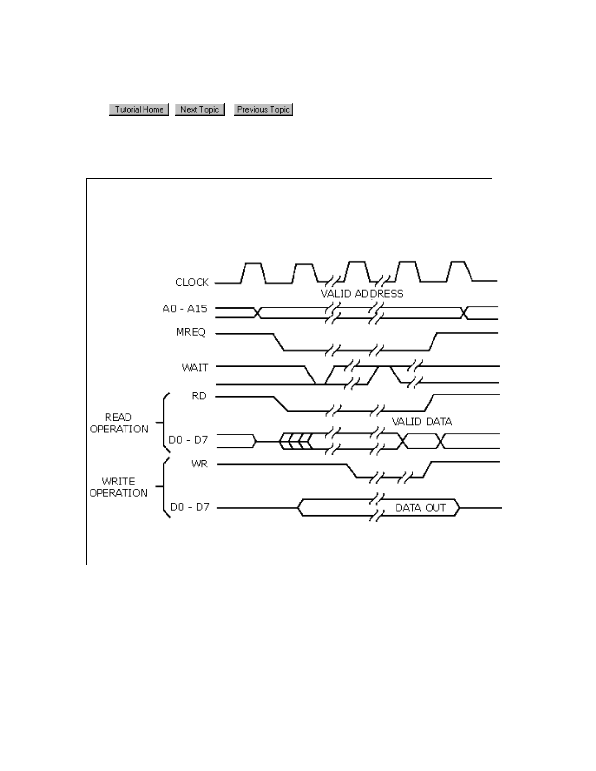
Sampling in the state analyzer
In the world of microprocessors, you can have both data and address appearing on the
same signal lines. To capture the correct data, the state analyzer has to restrict the
sampling of data to times when only the desired data is valid and appears on the signal
lines. It does this by sampling data from the same signal lines but with different clocks.
Example: The following timing diagram shows that to capture addresses, we want the
analyzer to sample when MREQ line goes low.
To capture data, we want the analyzer to sample when the WR line goes low (write cycle)
or when RD goes low (read cycle).
28
Page 29

Triggering the state analyzer
Similar to a timing analyzer, a state analyzer has the capability to qualify the data we
want to store. If we are looking for a specific pattern of highs and lows on the address
bus, we can tell the analyzer to start storing when it finds that pattern and to continue
storing until the analyzer's memory is full.
Simple Trigger Example: Looking at the "D" flip-flop shown below, data on the "D" input
is not valid until after a positive-going clock edge occurs. Thus, a valid state for the flipflop is when the clock input is high.
Now imagine that we have eight of these flip-flops in parallel. All eight are connected to
the same clock signal as shown below.
When a high level occurs on the clock line, all eight capture data at their "D" inputs.
Again, a valid state occurs each time there is a positive level on the clock line.
The following simple trigger tells the analyzer to collect data on lines D0 - D7 when a high
level is on the clock line.
29
Page 30

Advanced Trigger Example: You want to see what data is stored in memory at the
address value 406F6. You configure the advanced trigger to look for the pattern 406F6
(hexadecimal) on the address bus and a high level on the RD (memory read) clock line.
As you configure the Edge And Pattern trigger dialog, try to think of it as constructing a
sentence that reads left-to-right.
"Find the first occurrence of a Bus named ADDR, and on All bits a pattern that Equals
406F6 Hex, And a Signal named RD with a High level. Then Trigger and fill memory
with Anything.
30
Page 31

Probing options
General Purpose Probing (Standard)
Adapter to board connectors (Optional)
Analysis probes (Optional)
So far we've talked about some of the differences between scopes, timing and state
analyzers. Before we're ready to apply these new tools, we should talk about one more
subject – the probing system.
A scope probe is designed to gain easy access to the target system while minimizing the
signal distortion. Since we want to look at parametric information like voltage levels and
rise times, it is important that the probe doesn't load the circuit under test significantly. A
typical scope probe has 1 M ohm impedance shunted by 10 pF, depending on the
bandwidth required.
Logic analyzer probes are designed to allow connection of a high number of channels to
the target system easily by trading off amplitude accuracy of the signal under test.
Remember that a logic analyzer only distinguishes between two voltage levels!
Traditionally, logic analyzers used active probe pods, which had an integrated signal
detection circuitry for eight channels integrated. From these pods, we could connect with
leads to the circuit under test.
The typical impedance of a logic analyzer probe is in the area of 100 k ohm shunted by 8
pF at the input of the active pod. The connecting wires, however, add another 8 pF stray
capacitance, giving a total of 16 pF per channel.
General Purpose Probing
Physical connections to digital systems must be reliable and convenient to deliver
accurate data to the logic analyzer with minimum intrusion to the target system. The
standard general purpose probing solution shown below is shipped with the logic
analyzer. Each channel is terminated at both ends with 100k ohm and 8 pF.
31
Page 32

The standard set plugs directly into any .1-inch grid with 0.026 to 0.033-inch diameter
round pins or 0.025-inch square pins. All probe tips work with the Agilent Technologies
5059-4356 surface mount grabbers and the Agilent Technologies 5959-0288 through-hole
grabbers.
32
Page 33

Adaptor to board connectors
Both the 01650-63203 and the E5346A adapters include termination for the logic
analyzer. The 01650-63203 termination adapter plugs into a 2 x 10 pin header with 0.1
inch spacing. The E5346A high-density adapter connects to an AMP "Mictor 38"
connector.
Analysis Probes
Connecting a state analyzer to a microprocessor system requires some effort in terms of
mechanical connection and clock selection. Remember, we have to clock the state
analyzer whenever data or addresses on the bus are valid. With some microprocessors it
might be necessary to use external circuitry to decode several signals to derive the clock
for the state analyzer.
Analysis probes (formerly called preprocessors) are microprocessor-specific interfaces
that make it easier to probe buses. Generally, analysis probes consist of a circuit board
that attaches to the microprocessor (possibly through an adapter) and a configuration
file. The configuration file sets up the logic analyzer's clocks, buses, and signals correctly,
and may include an inverse assembler. The circuit board provides access to logical groups
of pins through headers designed to connect directly to the logic analyzer.
33
Page 34

Measurement overview
Turning on the logic analyzer
1. Plug in the power cable and press the front-panel On/Off button.
2. From the Windows Start bar, click Start>Programs>Agilent Logic
Analyzer>Agilent Logic Analyzer.
Optional: If you have a logic analyzer shortcut icon on screen, double-click the icon.
34
Page 35

Connecting to the target system
The standard probing that comes with the logic analyzer is the passive general purpose
probe with sixteen channels per cable. Each channel is terminated at both ends with 100k
ohm and 8 pF. With this type of probing, you can also disconnect the leads and plug the
cable connector directly into a connector on the device under test.
Note: In this tutorial, no probe connections are required. Later on in this tutorial, you are
asked to load a configuration file containing data to simulate the results of a probed device
under test. However, at this time, if you have the credit card demo board available, you
can connect it and capture real data for this tutorial.
As the number of channel connections increase, other probing options may be more
convenient.
35
Page 36

Credit card demo board
If you have a credit card demo board available, you can connect it as shown below and
capture the same data used in this measurement overview. Other benefits are that you
will see real activity indicators in the bus/signal setup dialog.
1. Connect the probe cable of Pod 1 into connector J1 of the demo board.
36
Page 37

Setting up bus/signal names
By default, the analyzer has two buses (My Bus 1 & 2) and two signals (My Signal 1 & 2)
configured in the interface. The following exercise cleans up the display defaults and reconfigures the analyzer bus/signal setup for a new measurement.
Delete bus/signal names
1. In the menu bar click Setup>Buses/Signals.
2. In the Analyzer Setup dialog that appears, right-click on My Bus 1, then select
Delete. Repeat until all bus signal names are deleted. After the last bus/signal
is deleted, "My Bus 1" appears again as a default name.
Tip: You can delete all bus/signal configurations at once with the Delete All
button.
Add new bus/signal name
1. In the Analyzer Setup dialog, right-click on My Bus 1, then select Rename.
2. From the popup keypad that appears, type in the new name "counter".
3. Select Ok.
37
Page 38

Map signals into the analyzer
The analyzer must be told which probed signals from the device under test are to be
included in the measurement, and how you want them grouped in the analyzer. In this
exercise, you assign channels 0 - 7 on Pod 1 under the name "counter". Notice that
when more than one channel is assigned to "counter" it becomes a bus.
1. Check the activity indicators for verification of proper connection to the target
system. You should see a transition arrow on all 8 channels.
Note: If you have the credit card demo board connected for this tutorial, you
will see activity indicators as shown below. If you will be loading the demo
configuration file (later in this tutorial) you will not see activity.
1. Click each channel assignment box under channels 0 - 7 on Pod 1. Notice that
as you assign channels, the configuration information is updated for the
bus/signal.
2. Click Ok.
38
Page 39

Setting the acquisition mode
Under the Sampling tab of the Analyzer Setup dialog is where you set the analyzer to be
either a timing or state analyzer. You also set either the timing options, such as memory
depth or sampling period, or the state clocking options.
1. From the menu bar, click Setup>Timing/State (Sampling)... ., or click the
icon in the toolbar.
2. Select Timing - Asynchronous Sampling.
3. Click Ok.
39
Page 40

Setting up a simple trigger
The Simple Trigger is a quick way to configure the analyzer to trigger on either a data
pattern on a bus, or an attribute of a single signal such as a rising edge or a low logic
level.
1. In the Simple Trigger, click on the pattern qualifier
2. Click in the text entry field
and enter the data pattern "E5".
and set it to Equal.
40
Page 41

Open the tutorial configuration file
At this point in a measurement, you would normally run the logic analyzer. However,
because you are not connected to a device under test, you cannot capture real data. You
will have to load a configuration file that contains this data.
Load the configuration file
1. Select File>Open.
2. From the file manager dialog, select the file named DemoConfig.ala from the
following directory: C:\Documents and Settings\All
Users\Documents\Agilent Technologies\Logic Analyzer\Provided
Configs\Agilent\Help Demo\
3. Select Open.
View the data
Notice how the logic analyzer triggered on data pattern E5 and placed it in the center of
the display. The red line shows that the trigger point is at the start of the data pattern
E5.
41
Page 42

Using markers
Markers are used for creating reference points in data. Once markers are placed in data,
you can use them to quickly see what time, sample, or data value the marker is set on.
To create a marker
1. From the menu bar, click Markers>New.
2. From the New Marker dialog that appears, configure the new marker and if
desired, specifically a position it in data. When you do not position the marker,
by default it is placed at the trigger point.
3. Select Ok.
To place a marker in data
When you first create a new marker, you have the option to place it in data at a specific
point in time or a specific sample number. The following exercise shows you other ways
to position markers in data.
1. In the display, click on marker M3 (your new marker) and while holding the
mouse button down, drag maker M3 to -100ns before trigger, then release.
Notice that the marker position value changes as you move it.
2. From the menu bar, click Markers>Place On Screen, then select M1 and click
Ok. Notice how M1 is placed at center screen at the red trigger line.
3. Point the mouse cursor at any desired point in data, then right-click and select
Place Marker. From the Place Marker dialog that appears, choose the M2
marker. Notice that the marker is placed where the mouse was pointing.
Go To a marker in data
Once you have markers set in data, you can quickly find any of them as follows.
1. From the menu bar, click Markers>GoTo.
2. Select the marker you want to find, and click Ok.
42
Page 43

Zooming in on the data
Data from a timing analyzer is displayed similarly to oscilloscope data. Both an analyzer
and scope display waveforms on a horizontal time axis. Therefore to zoom in or out on a
waveform, change the Scale (time/division) of the time axis of the waveform.
Both state and timing analyzers can have multiple signals grouped together in a bus. To
get a view of all signals, you can expand a bus into individual signals.
Expand a bus
Click the "+" symbol just to the left of the bus named "counter". The collection of signals
under "counter" breaks out into individual signals named counter[0] - counter[7].
Change the scale
Click the zoom out icon to expand the signals to where you want them.
43
Page 44

Time saving tasks
Loading and saving configuration files
Many times it is quicker to open an existing configuration file with a similar setup than to
create a new configuration from scratch. You simply open a similar file, make the
appropriate changes to the setup, then save the file as a new filename.
Note: When you rename an existing configuration file, you retain the saved trigger
setups and "Find" search favorites from the first configuration file.
You already have learned how to open a configuration file. In the following exercise, you
will save the "democonfig" file to a new name.
1. From the menu bar, click File>Save As... .
2. From the file manager dialog that appears, type in the new name "myconfig",
then click Save.
44
Page 45

Saving and recalling trigger setups
Each time you setup a new trigger and run the measurement, the trigger setup is stored
in the analyzer. It is quicker to recall a trigger setup rather than re-configure the trigger
setup each time.
Note: The analyzer must be run before the trigger setup is stored. Also, trigger setups
are stored as part of the configuration file. If you load a new configuration file, the trigger
setups will be overwritten by trigger setups stored with the new file.
To recall a trigger setup
1. From the menu bar, click Setup>Recall Trigger.
2. From the lower list, select the desired trigger setup, then click Ok.
Tip: When the list of most recently used triggers get long, you can store the most
often used triggers in the upper favorites list.
45
Page 46

Quick marker measurements
You can quickly read the time or number of samples between markers.
1. Click Markers>New Interval Measurement.
2. Configure the Interval dialog to display the Time from M1 to M2 as shown below,
then click Ok.
The result of the interval measurement is displayed in the marker
measurements display bar.
3. Click Markers>New Value At Measurement.
4. Configure the Value At dialog to display the Hex value of counter at M1 as
shown below, then click Ok.
The result of the value at measurement is displayed in the marker
measurement display bar.
46
Page 47

Searching data
You can search for a data pattern on a bus, or a single signal. You can also choose when
the search begins and ends. Finally, you can save the search criterion in a favorites list.
1. From the menu bar, click Edit>Find.
2. From the Find dialog that appears, configure the search criterion as shown below
to find "AA".
3. Select Ok.
As you configure the Find dialog, try to think of it as constructing a sentence that reads
left-to-right.
"Find the 1st occurrence from Display Center, on a Bus named counter, including All
bits, a pattern that Equals AA".
47
Page 48

Toolbars, tooltips and mouse shortcuts
Throughout this tutorial, the menu bar has been used to access features. There are two
other ways to access features as well as other useful tips that can save you time.
Toolbars
Below the menu bar are groups of icons that represent shortcuts to many dialogs and
features. For more information refer to Toolbars in the main help.
Mouse shortcuts
There are many mouse shortcuts available. To access them simply point the mouse over
a screen element such as a marker, or screen area, then right-click the mouse. Mouse
shortcuts are especially useful within the waveform and listing data display areas.
Tooltips
Tooltips are small information displays that appear during operations such as moving
markers, setting a trigger with the mouse, or hovering the mouse over a bus/signal
name. Use them as comments, or to monitor your progress or current positions.
48
Page 49

Measurement Examples
The following measurement examples show you the typical order of steps to setup and
run a measurement. As you go through the examples, you will encounter steps such as
probing or triggering where alternative choices are available. In these steps, select the
probing or trigger example that best fits your measurement.
Making a timing analyzer measurement
Making a state analyzer measurement
To trigger other instruments - Trigger out
To trigger the analyzer from another instrument - Trigger in
See Also
Tutorial - Getting to know your logic analyzer
Timing mode trigger functions
State mode trigger functions
Making marker measurements
49
Page 50

Making a timing analyzer measurement
The following measurement example shows you the steps necessary to configure and run
the logic analyzer for a typical timing analyzer measurement. As you go through the
example, make the appropriate choices from the selection lists that best match the kind
of configuration you need.
Tip: If you are new to logic analysis, refer to "Getting to know your logic analyzer"
for a quick tutorial on logic analysis concepts and measurements.
1. Connect the to the device under test.
2. Turn on the logic analyzer.
Bus and signal setup
3. In the menu bar, select Setup>Bus/Signal... .
4. From the Buses/Signals tab, assign bus/signal names to the probed signals on the
target system. You do this by either renaming existing names, or deleting and
creating new names.
5. From the Buses/Signals tab, assign channels under the appropriate pods for all
probed buses/signals on the device under test.
Acquisition mode setup
6. In the Analyzer Setup dialog, select the Sampling tab.
7. From the Sampling tab, set the acquisition mode to Timing - Asynchronous
Sampling.
8. Set the Sampling Options.
9. Set the Sampling Period.
Trigger setup
10. The trigger required to capture specific data depends on the measurement.
From within the data display, setup a
From the Advanced Trigger dialog, setup a timing mode
Run the measurement
11. Run the measurement.
See Also
To set the trigger position
To set acquisition depth
However, the trigger is generally set in two ways.
.
function.
50
Page 51

Making a state analyzer measurement
The following measurement example shows you the steps necessary to configure and run
the logic analyzer for a typical state analyzer measurement. As you go through the
example, make the appropriate choices from the selection lists that best match the kind
of configuration you need.
Tip: If you are new to logic analysis, refer to "Getting to know your logic analyzer"
for a quick tutorial on logic analysis concepts and measurements.
1. Connect the to the device under test.
Note: Be sure that the clock signals of your device under test are connected to
clock channels on the pods. Any unused clock channels can be used for additional
data channels and will not feed into the state clock setup.
2. Turn on the logic analyzer.
Bus and signal setup
3. In the menu bar, select Setup>Bus/Signal... .
4. From the Buses/Signals tab, assign bus/signal names to the probed signals on the
target system. You do this by either renaming existing names, or deleting and
creating new names.
5. From the Buses/Signals tab, assign channels under the appropriate pods for all
probed buses/signals on the device under test.
Acquisition mode setup
6. In the Analyzer Setup dialog, click the Sampling tab.
7. From the Sampling tab, set the acquisition mode to State - Synchronous
8. Set the state clock type.
9. Set the state clock qualifiers.
10. If necessary, set the advanced state clocking.
Trigger setup
11. The trigger required to capture specific data depends on the measurement.
From within the data display, set up a
From the Advanced Trigger dialog, set up an function.
Run the measurement
12. Run the measurement.
See Also
To set the trigger position
To set acquisition depth
Sampling.
However, the trigger is generally set in two ways.
.
51
Page 52

External Triggering
There are Trigger In and Trigger Out BNC connectors located on the logic analyzer
(rear panel of 1680-series and front panel of 1690-series). Use them to connect the
analyzer to an external instrument and either send or receive a trigger signal.
Trigger signal characteristics
Trigger out signal:
The trigger out signal is designed to drive a 50 Ohm load. It is recommended that for
good signal quality, the trigger out signal be terminated in 50 Ohms to ground.
VOH (output high level) = >2.0 V.
VOL (output low level) = <0.5 V.
Pulse width = Approximately 60 ns to 140 ns.
Signal type is set in the System Options dialog. System Options is reached by
Edit>Options.
Trigger in signal:
TTL, ECL, or user defined 5.5 V Max.
Edge type is set in the System Options dialog. System Options is reached by
Edit>Options.
The following tasks show you how to configure the analyzer for external triggering. For
an example of a complete analyzer measurement, refer to the measurement examples
listed below under See Also.
To trigger other instruments - trigger out
To trigger analyzer from another instrument - trigger in
To trigger other instruments - Trigger Out
1. Connect a BNC cable from the Trigger Out BNC to the external instrument you
want to trigger.
2. Configure the logic analyzer as you would normally for any other measurement.
Refer to See Also below.
3. When the analyzer's trigger sequence becomes true and the analyzer triggers, a
trigger signal is sent out through the Trigger Out BNC to the external
instrument.
To trigger analyzer from another instrument Trigger In
1. Connect a BNC cable from the Trigger In BNC to the external instrument that
will send the trigger signal.
2. Configure the logic analyzer as you would normally for any other measurement.
Refer to See Also.
3. From the menu bar select Setup>Advanced Trigger.
4. From the Trigger dialog, select the Other tab, then select the Wait for external
arm trigger function.
52
Page 53

5. When the logic analyzer receives the external arm signal (trigger signal), it arms
See Also
Making a state analyzer measurement
Making a timing analyzer measurement
Wait for external arm - (state)
Wait for external arm - (timing)
and begins to evaluate its trigger sequence. When the trigger sequence becomes
true, the analyzer triggers.
53
Page 54

Making marker measurements
Making marker measurements
Once a marker is created, you can use it as a reference point in the data when measuring
intervals or viewing the data value at the marker.
To create a new interval measurement
To create a new value at measurement
See Also
Working with markers
54
Page 55

To create a new interval measurement
Use the new interval measurement feature to measure a time interval, or the number of
samples between two specified points in data. Measurement results are displayed in the
marker measurement display bar.
Note: Marker measurements use either the default M1 and M2 markers, or any other
user-defined markers.
1. From the menu bar select Markers>New Interval Measurement, or click the
icon in the markers toolbar.
2. Select either time or sample, then select the markers you want to measure
between.
3. Click OK.
The result of the interval measurement
measurements display bar.
See Also
To create a new value at measurement
is displayed in the marker
55
Page 56

To create a new value at measurement
Use the new value at measurement feature to measure the value of a bus or a single
signal at a specified marker location in data. Measurement results are displayed in the
marker measurement display bar.
Note: Marker measurements use either the default M1 and M2 markers, or any other
user-defined markers.
1. From the menu bar select Markers>New Value At Measurement, or click the
icon in the markers toolbar.
2. Select the numeric base of the data, the bus or signal source, then the
marker.
3. Click OK.
The result of the value at measurement
measurement display bar.
See Also
To create a new interval measurement
is displayed in the marker
56
Page 57

Trigger Functions
Timing mode trigger functions
State mode trigger functions
Timing mode trigger functions
The following trigger setup examples are available as Trigger Functions in the Advanced
Trigger dialog when in the timing acquisition mode. To see these trigger setups in the
context of an example measurement refer to "Making a timing analyzer measurement".
Edge
Edge
"N" number of edges
Edge and Pattern
Edge followed by edge
Edges too far apart
Edge followed by pattern
Pattern too late after edge
Bus Pattern
Pattern
Edge And Pattern
Pattern present for > "T" time
Pattern present for < "T" time
Pattern absent for > "T" time
Pattern absent for < "T" time
Edge followed by pattern
Pattern too late after edge
Other
Find anything "N" times
Reset and start timer
Width violation on pattern or pulse
Wait "T" seconds
Run until user stop
Wait for external arm
Advanced
Advanced If/Then
Advanced 2-Way Branch
Advanced 3-Way Branch
Advanced 4-Way Branch
Pattern "AND" Pattern
Pattern "OR" Pattern
57
Page 58

State mode trigger functions
The following trigger setup examples are available as Trigger Functions in the Advanced
Trigger dialog when in the state acquisition mode. To see these trigger setups in the
context of an example measurement refer to "Making a state analyzer measurement".
Patterns
Pattern "N" times
"N" consecutive samples with Pattern1
Pattern1 followed by Pattern2
Pattern1 immediately followed by Pattern2
Pattern1 followed by Pattern2 before Pattern3
Too few states between Pattern1 and Pattern2
Too many states between Pattern1 and Pattern2
Pattern2 occurring too soon after Pattern1
Pattern2 occurring too late after Pattern1
Other
Reset and start timer
Find anything "N" times
Run until user stop
Wait for external arm
Wait "N" external clock states
Advanced
Advanced If/Then
Advanced 2-Way Branch
Advanced 3-Way Branch
Advanced 4-Way Branch
Pattern AND Pattern
Pattern OR Pattern
See Also
External Triggering
58
Page 59

Timing Mode
Timing mode trigger functions
Edge
Edge
"N" number of edges
Edge and Pattern
Edge followed by edge
Edges too far apart
Edge followed by pattern
Pattern too late after edge
Bus Pattern
Pattern
Edge and Pattern
Pattern present for > "T" time
Pattern present for < "T" time
Pattern absent for > "T" time
Pattern absent for < "T" time
Edge followed by pattern
Pattern too late after edge
Other
Find anything "N" times
Reset and start timer
Width violation on pattern or pulse
Wait "T" seconds
Run until user stop
Wait for external arm
Advanced
Advanced If/Then
Advanced 2-Way Branch
Advanced 3-Way Branch
Advanced 4-Way Branch
Pattern "AND" Pattern
Pattern "OR" Pattern
See Also
State mode trigger functions
To build a trigger sequence
To store a trigger
To recall a trigger
Simple Trigger
59
Page 60

Edge
This trigger function is available when the acquisition mode is set to Timing Asynchronous. The analyzer triggers when a user-defined edge occurs.
To edit this function
To insert events and actions
To modify trigger step display
To negate a function statement
60
Page 61

"N" number of edges
This trigger function is available when the acquisition mode is set to Timing Asynchronous. The analyzer triggers when the "Nth" occurrence of a user-defined edge
occurs.
To edit this function
To insert events and actions
To modify trigger step display
To negate a function statement
61
Page 62

Edge followed by edge
This trigger function is available when the acquisition mode is set to Timing Asynchronous. The analyzer triggers when edge 2 occurs within a specified time period
after edge 1.
To edit this function
To insert events and actions
To modify trigger step display
To negate a function statement
62
Page 63

Edge followed by pattern
This trigger function is available when the acquisition mode is set to Timing Asynchronous. The analyzer triggers when a bus pattern occurs within a specified time
period after an edge.
To edit this function
To insert events and actions
To modify trigger step display
To negate a function statement
63
Page 64

Edges too far apart
This trigger function is available when the acquisition mode is set to Timing Asynchronous. The analyzer triggers when edge 2 does not occur within a specified
time period after edge 1.
To edit this function
To insert events and actions
To modify trigger step display
To negate a function statement
64
Page 65

Pattern
This trigger function is available when the acquisition mode is set to Timing Asynchronous. The analyzer triggers when a designated bus pattern occurs.
To edit this function
To insert events and actions
To modify trigger step display
To negate a function statement
65
Page 66

Edge and Pattern
This trigger function is available when the acquisition mode is set to Timing Asynchronous. The analyzer triggers when both a user-defined edge and bus pattern
occur at the same time.
To edit this function
To insert events and actions
To modify trigger step display
To negate a function statement
66
Page 67

Pattern present for > "T" time
This trigger function is available when the acquisition mode is set to Timing Asynchronous. The analyzer triggers when a user-defined bus pattern is present
greater than a specified time period.
To edit this function
To insert events and actions
To modify trigger step display
To negate a function statement
67
Page 68

Pattern present for < "T" time
This trigger function is available when the acquisition mode is set to Timing Asynchronous. The analyzer triggers when a user-defined bus pattern is present less
than a specified time period.
To edit this function
To insert events and actions
To modify trigger step display
To negate a function statement
68
Page 69

Pattern absent for > "T" time
This trigger function is available when the acquisition mode is set to Timing Asynchronous. The analyzer triggers when a user-defined bus pattern is absent greater
than a specified time period.
To edit this function
To insert events and actions
To modify trigger step display
To negate a function statement
69
Page 70

Pattern absent for < "T" time
This trigger function is available when the acquisition mode is set to Timing Asynchronous. The analyzer triggers when a user-defined bus pattern is absent less
than a specified time period.
To edit this function
To insert events and actions
To modify trigger step display
To negate a function statement
70
Page 71

Pattern too late after edge
This trigger function is available when the acquisition mode is set to Timing Asynchronous. The analyzer triggers when a specified bus pattern does not occur
within a specified time period after an edge.
To edit this function
To insert events and actions
To modify trigger step display
To negate a function statement
71
Page 72

Pattern "AND" Pattern (timing)
This trigger function is available when the acquisition mode is set to Timing Asynchronous. The analyzer triggers when both pattern1 "AND" pattern2 occur at the
same time, and for the specified numbers of samples (occurs).
To edit this function
To insert events and actions
To modify trigger step display
To negate a function statement
72
Page 73

Pattern "OR" Pattern (timing)
This trigger function is available when the acquisition mode is set to Timing Asynchronous. The analyzer triggers when either pattern1 "OR" pattern2 occurs for the
specified numbers of samples (occurs).
To edit this function
To insert events and actions
To modify trigger step display
To negate a function statement
73
Page 74

Find anything "N" times (timing)
This trigger function is available when the acquisition mode is set to Timing Asynchronous. The analyzer triggers when it sees any data (Anything) for the Nth time.
To edit this function
To insert events and actions
To modify trigger setup display
To negate a function statement
74
Page 75

Width violation on pattern or pulse
This trigger function is available when the acquisition mode is set to Timing Asynchronous. The analyzer triggers when a pulse or bus pattern is found that is either
too narrow or too wide.
To edit this function
To insert events and actions
To modify trigger step display
To negate a function statement
75
Page 76

Wait "T" seconds
This trigger function is available when the acquisition mode is set to Timing Asynchronous. The analyzer triggers after the specified time period expires.
To edit this function
To insert events and actions
To modify trigger step display
To negate a function statement
76
Page 77

Wait for external arm (timing)
This trigger function is available when the acquisition mode is set to Timing Asynchronous. The analyzer triggers when an external arming signal appears through
the external trigger in port. The external trigger port is located on the rear panel of the
168X models and the front panel of the 169X models.
To edit this function
To insert events and actions
To modify trigger step display
To negate a function statement
77
Page 78

Run until user stop (timing)
This trigger function is available when the acquisition mode is set to Timing Asynchronous. This trigger function sets up to never trigger. You must select the stop
button to view the captured data.
To edit this function
To set store qualification
To insert events and actions
To modify trigger step display
To negate a function statement
78
Page 79

Reset and start timer (timing)
Note: This trigger function is not available in the 1683A/93A models because they do
not have timers available.
This trigger function is available when the acquisition mode is set to Timing -
Asynchronous. This trigger function resets a timer, then starts the timer for a specified
period of time. This trigger function requires that the timer value be set in either the
same trigger step, or another trigger step that follows. When the timer stops, the
analyzer triggers. For more information refer to "To configure a timer".
To edit this function
To insert events and actions
To modify trigger step display
To negate a function statement
79
Page 80

Advanced If/Then (timing)
This trigger function is available when the acquisition mode is set to Timing Asynchronous. The analyzer triggers when the "If" clause becomes true.
To edit this function
To insert events and actions
To modify trigger step display
To negate a function statement
80
Page 81

Advanced 2-Way Branch (timing)
This trigger function is available when the acquisition mode is set to Timing Asynchronous. The two-way branch is evaluated true when either of two patterns (if or
Else if) are found. Depending on which pattern is found true, the appropriate "Then"
action is executed.
To edit this function
To insert events and actions
To modify trigger step display
To negate a function statement
81
Page 82

Advanced 3-Way Branch (timing)
This trigger function is available when the acquisition mode is set to Timing Asynchronous. The three-way branch is evaluated true when either of three patterns
(If or Else if) are found. Depending on which pattern is found true, the appropriate
"Then" action is executed.
To edit this function
To insert events and actions
To modify trigger step display
To negate a function statement
82
Page 83

Advanced 4-Way Branch (timing)
This trigger function is available when the acquisition mode is set to Timing Asynchronous. The four-way branch is evaluated true when either of four patterns (If
or Else if) are found. Depending on which pattern is found true, the appropriate "Then"
action is executed.
To edit this function
To insert events and actions
To modify trigger step display
To negate a function statement
83
Page 84

State Mode
State mode trigger functions
Patterns
Pattern "N" times
"N" consecutive samples with Pattern1
Pattern1 followed by Pattern2
Pattern1 immediately followed by Pattern2
Pattern1 followed by Pattern2 before Pattern3
Too few states between Pattern1 and Pattern2
Too many states between Pattern1 and Pattern2
Pattern2 occurring too soon after Pattern1
Pattern2 occurring too late after Pattern1
Other
Reset and start timer
Find anything "N" times
Run until user stop
Wait for external arm
Wait "N" external clock states
Advanced
Advanced If/Then
Advanced 2-Way Branch
Advanced 3-Way Branch
Advanced 4-Way Branch
Pattern "AND" Pattern
Pattern "OR" Pattern
See Also
Timing mode trigger functions
To build a trigger sequence
To set store qualification
To store a trigger
To recall a trigger
Simple Trigger
84
Page 85

Pattern "N" times
This trigger function is available when the acquisition mode is set to State Synchronous. It will trigger the logic analyzer when it finds the nth occurrence of a bus
pattern as shown below.
To edit this function
To set store qualification
To insert events and actions
To modify trigger step display
To negate a function statement
85
Page 86

"N" consecutive samples with Pattern1
This trigger function is available when the acquisition mode is set to State Synchronous. It will trigger the logic analyzer when a bus pattern occurs a specified
number times.
To edit this function
To set store qualification
To insert events and actions
To modify trigger step display
To negate a function statement
86
Page 87

Pattern1 followed by Pattern2
This trigger function is available when the acquisition mode is set to State Synchronous. It will trigger the logic analyzer when pattern2 occurs eventually after
pattern 1.
To edit this function
To set store qualification
To insert events and actions
To modify trigger step display
To negate a function statement
87
Page 88

Pattern1 immediately followed by Pattern2
This trigger function is available when the acquisition mode is set to State Synchronous. It will trigger the logic analyzer when pattern 2 is found immediately after
exiting pattern 1.
To edit this function
To set store qualification
To insert events and actions
To modify trigger step display
To negate a function statement
88
Page 89

Pattern1 followed by Pattern2 before Pattern3
This trigger function is available when the acquisition mode is set to State Synchronous. It will trigger the logic analyzer when pattern2 occurs eventually after
pattern1, for a specified number of times, without pattern3 occurring in between.
To edit this function
To set store qualification
To insert events and actions
To modify trigger step display
To negate a function statement
89
Page 90

Too few states between Pattern1 and Pattern2
This trigger function is available when the acquisition mode is set to State Synchronous. It will trigger the logic analyzer when pattern1 is followed by pattern2
with fewer than "N" specified states in between.
To edit this function
To set store qualification
To insert events and actions
To modify trigger step display
To negate a function statement
90
Page 91

Too many states between Pattern1 and Pattern2
This trigger function is available when the acquisition mode is set to State Synchronous. It will trigger the logic analyzer when pattern1 is followed by pattern2
with more than "N" specified states in between.
To edit this function
To set store qualification
To insert events and actions
To modify trigger step display
To negate a function statement
91
Page 92

Pattern2 occurring too soon after Pattern1
This trigger function is available when the acquisition mode is set to State Synchronous. It will trigger the logic analyzer when pattern2 occurs within a specified
time period after pattern1.
To edit this function
To set store qualification
To insert events and actions
To modify trigger step display
To negate a function statement
92
Page 93

Pattern2 occurring too late after Pattern1
This trigger function is available when the acquisition mode is set to State Synchronous. It will trigger the logic analyzer when pattern2 does not occur within a
specified time period after pattern1.
To edit this function
To set store qualification
To insert events and actions
To modify trigger step display
To negate a function statement
93
Page 94

Find anything "N" times (state)
This trigger function is available when the acquisition mode is set to State Synchronous. It will trigger the logic analyzer when any data (Anything) is seen for the
Nth time. It is commonly used to create an immediate trigger, or a trigger after a userdefined delay.
To edit this function
To set store qualification
To insert events and actions
To modify trigger step display
To negate a function statement
94
Page 95

Run until user stop (state)
This trigger function is available when the acquisition mode is set to State Synchronous. This trigger function sets up to never trigger. You must select the stop
button to view the captured data.
To edit this function
To set store qualification
To insert events and actions
To modify trigger step display
To negate a function statement
95
Page 96

Reset and start timer (state)
Note: This trigger function is not available in the 1683A/93A models because they do
not have timers available.
This trigger function is available when the acquisition mode is set to State -
Synchronous. This trigger function resets a timer, then starts the timer for a specified
period of time. This trigger function requires that the timer value be set in either the
same trigger step, or another trigger step that follows. When the timer stops, the
analyzer triggers. For more information refer to "To configure a timer".
To edit this function
To set store qualification
To insert events and actions
To modify trigger step display
To negate a function statement
96
Page 97

Wait for external arm (state)
This trigger function is available when the acquisition mode is set to State Synchronous. The analyzer triggers when an external arming signal appears through
the external trigger in port. The external trigger port is located on the rear panel of the
168X models and the front panel of the 169X models.
To edit this function
To set store qualification
To insert events and actions
To modify trigger step display
To negate a function statement
97
Page 98

Wait "N" external clock states
This trigger function is available when the acquisition mode is set to State Synchronous. The analyzer triggers on the "Nth" occurrence of the external clock signal
(plus any user-defined clock qualification) from the device under test.
To edit this function
To set store qualification
To insert events and actions
To modify trigger step display
To negate a function statement
98
Page 99

Pattern "AND" Pattern (state)
This trigger function is available when the acquisition mode is set to State Synchronous. The analyzer triggers when both pattern1 "AND" pattern2 occur at the
same time, and for the specified numbers of samples (occurs).
To edit this function
To set store qualification
To insert events and actions
To modify trigger step display
To negate a function statement
99
Page 100

Pattern "OR" Pattern (state)
This trigger function is available when the acquisition mode is set to State Synchronous. The analyzer triggers when either pattern1 "OR" pattern2 occurs for the
specified numbers of samples (occurs).
To edit this function
To set store qualification
To insert events and actions
To modify trigger step display
To negate a function statement
100
 Loading...