

Page 1

Getting There Just Got Easier
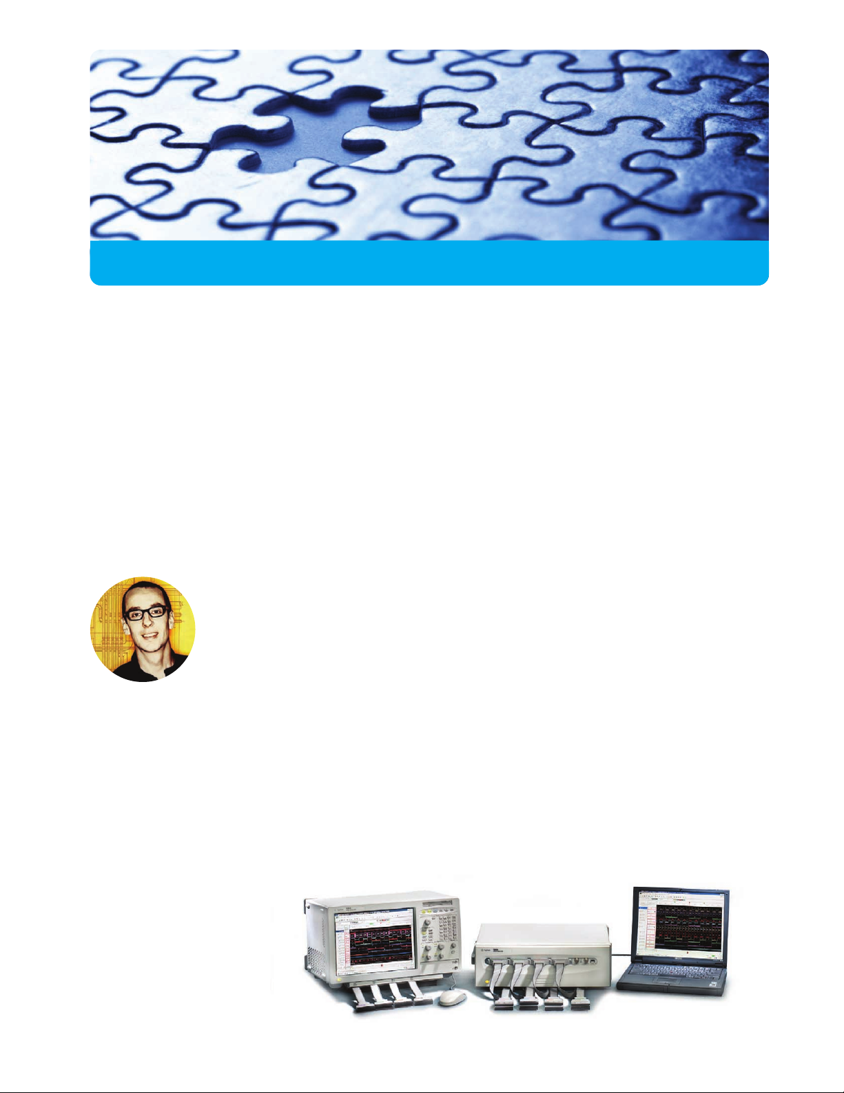
Agilent 1680 and 1690 Series Logic Analyzers
Solve critical digital design problems faster
Page 2
Getting there just got easier
When you’re debugging a design, you need to focus on solving your problems—not on mastering
your debug tools. That’s the thinking behind Agilent Technologies’ new 1680 and 1690 series of
logic analyzers. These instruments work intuitively, so you can answer critical design questions
without first becoming an expert in measurement instruments.
®
You’ll understand your logic analyzer right out of the box—thanks to the familiar Windows
features, the easy-to-navigate interface and the straightforward triggering. High performance
doesn’t mean difficult to operate. Just turn the instrument on and you’re ready to solve.
.............................................................................................
Performance with Headroom
You get accurate and reliable measurements for today’s processors
and buses, with power to cover future technology trends:
• 200 MHz state
• Up to 800 MHz timing with 4 M of memory depth
• 200 MHz transitional timing
-based
Instant Familiarity and Insights
The single-screen operation, intuitive triggering and familiar Windows
interface provide answers quickly and easily—so you can focus on
debugging your design.
Fitting Your Work Style
Small-footprint benchtop and PC-hosted models are available for integration
into your debug environment. And offline analysis capabilities allow you to
continue making measurements while you work at getting answers. These
instruments work the way you work.
2
Page 3
Windows Familiarity and Single-Screen Operation
A familiar Windows-based user interface takes the complexity out of making logic analyzer
measurements. You’ll feel right at home from the moment you turn on the instrument.
And if you haven’t used your logic analyzer in a while, you won’t have to spend hours
getting reacquainted with its features.
.........................................................................................
Perform all operations directly from
the main screen—as you would with
a PC application such as Microsoft
Word or Excel.
Access the most frequently used
features via icons.
Select advanced features from the
standard Windows menu bar.
®
Expand/compress buses with
Windows-like +/- symbols.
.........................................................................................
Three measurement modes
State Analysis
State analysis uses a signal from your
system under test to determine when to
sample. Because state analysis samples
are synchronous to the system under
test, they provide a view of what your
system is executing. You can capture
microprocessor and bus cycles and
then convert the data into processor
mnemonics or bus transactions with
inverse assemblers from Agilent or one
of our third-party partners.
Timing Analysis
Timing analysis uses the logic analyzer’s
internal clock to determine when to sample
system activity. With up to 800 MHz
sampling and 4 M deep memory, you’ll see
the order of events with high resolution
over a long period of time.
Transitional Timing
If your system has bursts of activity
followed by times with little activity,
you can use transitional timing to
capture a longer period of system
activity. In transitional timing, the
analyzer samples data at regular
intervals but stores the data only
when there is a transition on one
of the signals.
3
Page 4
When you know what you want to capture,
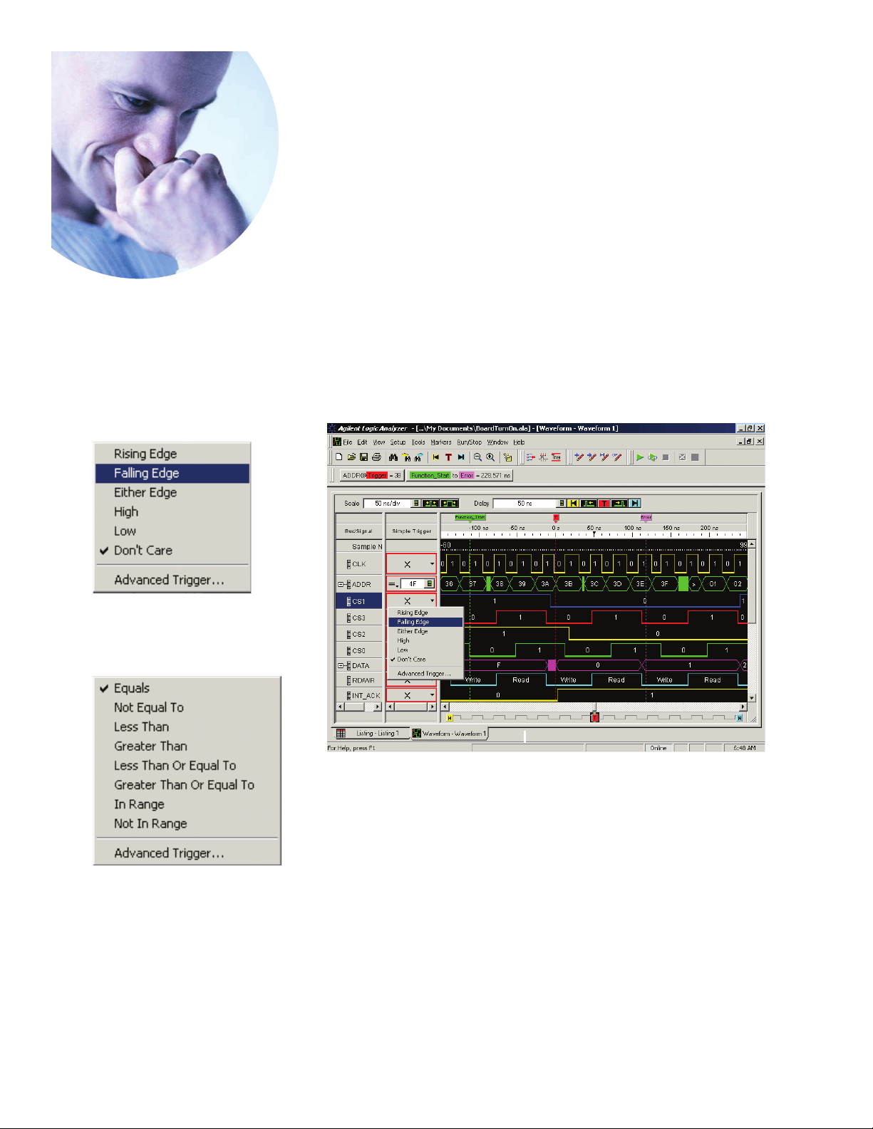
Selections for individual signals
trigger the way you think
.............................................................
During board turn-on and system debug, Agilent’s straightforward triggering
capabilities help you quickly narrow in on the root cause of a problem.
You can capture every aspect of your design, from a simple stuck bit to the
complex sequence of events leading up to a timing problem. The intuitive
triggering helps you identify the cause of elusive problems in less time—so
you can get to your solution quickly.
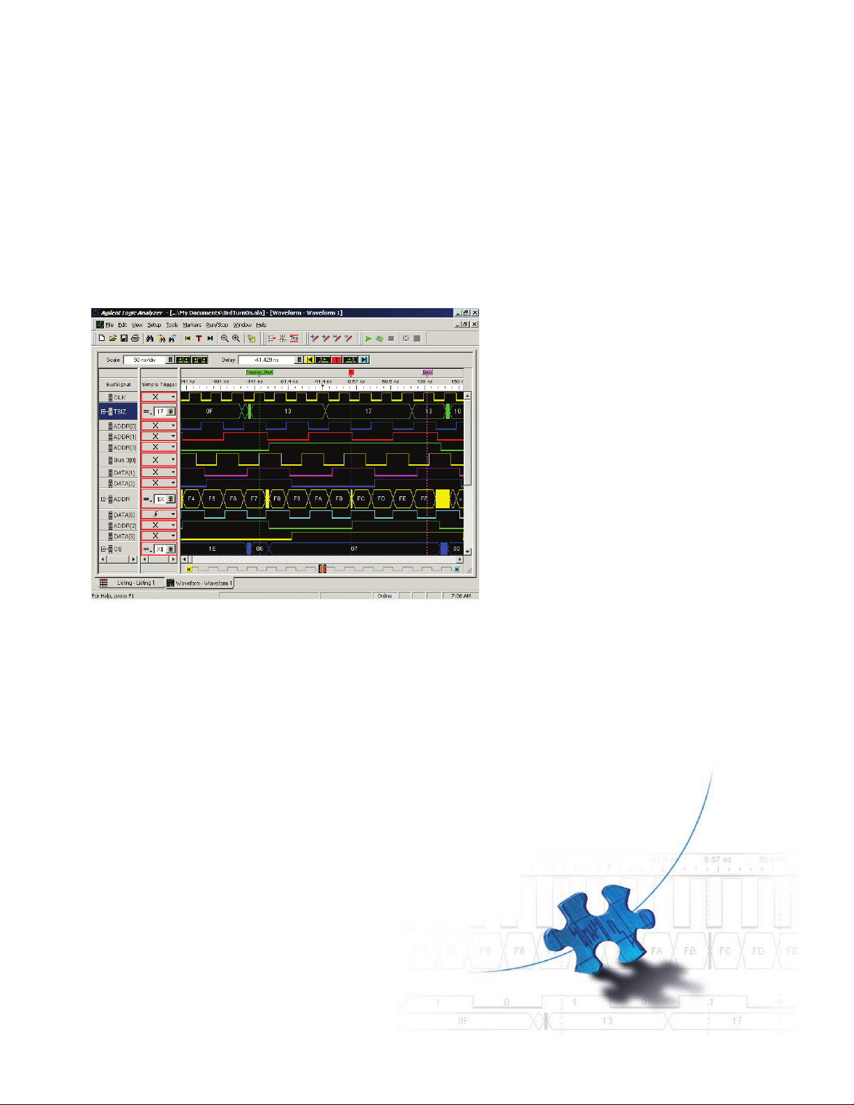
Qualification selections for bus patterns
Simple Trigger
Set the trigger according to how you think
about your target signals. Use standard
events, such as rising edge, falling edge
or pattern, to define a trigger event.
These events are accessible via an easy
pull-down menu.
You can set the trigger for an event on the
basis of activity on one or more buses or
signals. Simply select the patterns, edge
or levels for the signals that apply.
4
Page 5

Set Quick Trigger
See something you didn’t expect in
the current trace? Simply draw a box
around the questionable event and select
Set Quick Trigger to see if it occurs again.
You don’t have to spend time defining
the trigger. The instrument does the
work for you.
Advanced Trigger
With the Advanced Trigger, you can customize a trigger for your specific situation.
You can use trigger functions as individual
trigger events or as building blocks for
complex scenarios.
Icons provide a graphical representation
for each trigger function. Simply drag-anddrop an icon into the trigger sequence. To
fully define the trace event, fill in the
blanks with values or select standard
options from the pull-down menu.
Trigger History/Recall
Save and name each trigger to create a
series of your favorite triggers. Recall a
previous trigger to test your latest defect
fix. Have the confidence of knowing you
can make the same measurement later
without having to spend time setting up
the instrument.
www.agilent.com/find/digitaldesign
5
Page 6

Benchtop 1680 series
442.70 mm
17.429 in.
442.70 mm
17.429 in.
384.53 mm
15.139 in.
256.71 mm
10.107 in.
....................................................................
Agilent’s 1680 series benchtop logic analyzers feature a 12.1-inch color display and
convenient knobs and hot keys. A glance at the interface provides quick insights on
your measurements, as well as information on the status of the instrument.
The 12.1-inch color display allows you to
see more data. Viewing relationships
between large amounts of signals and
buses helps you identify a problem sooner.
Backlit LEDs show you the current logic
analyzer settings at a glance.
Front panel knobs let you quickly change
the vertical and position settings of the
display. You can accurately place unlimited
markers to make critical timing measurements.
Cable flexibility allows you to conveniently access your target from the front or
back of the benchtop 1680 series.
A Default Setup key returns the logic
analyzer to a known state—an important
feature if you share your logic analyzer.
The small footprint saves valuable
workspace.
6
Page 7

Back panel of the benchtop 1680 series
Connecting to your world
Each measurement you take provides
additional clues to the cause of your
design problems. Because access to your
captured traces and the answers they
provide is critical, your Agilent 1680 series
benchtop logic analyzer gives you several
options for data storage, retrieval and
sharing.
A 10/100Base-T LAN interface lets you
easily print waveforms on networked
printers, save your results on your office
PC, and share information with others.
The hard-drive capacity—15 GB mini-
mum—allows you to store all of your
setups and results for future recall.
The 1.44 MB floppy drive makes it easy
to save your setups to standard 3.5-inch
floppy disks.
Two IEEE 1394 ports enable connection
of external hard drives or read/write
CD-ROM drives for data storage and
retrieval.
Two USB ports enable the hot connection
of mouse or keyboards.
A mouse lets you point and click with
ease, or you can choose a different pointing device that best meets your needs.
A small keyboard is standard.
Trigger In/Trigger Out BNCs allow you
to trigger or arm external devices and to
receive signals that can be used to arm
the logic analyzer.
A parallel printer port lets you print
hard copies of screen graphics for project
documentation.
An external video port allows you to
connect large displays.
A 24x CD-ROM drive is used to update
system software.
www.agilent.com/find/digitaldesign
7
Page 8

PC-hosted 1690 series
..................................................................
Agilent’s 1690 series PC-hosted logic analyzers provide the lowest price point for
high-performance logic analysis. They allow you to carry out your debug work in
your familiar PC environment.
...........................................................................................
An IEEE 1394 port provides direct connection to a 500 MHz minimum Intel
or AMD K-6 II (or equivalent) PC running
Windows 2000 Professional. Purchase
additional quantities of E5851A (IEEE 1394
PCI card and cable) so the instrument can
be shared throughout the team.
®
Celeron
PC-hosting allows you to see your design
with the same display size and resolution
of your regular working environment.
Trigger In/Trigger Out BNCs allow you
to trigger or arm external devices and
to receive signals that can be used to
arm the logic analyzer.
Cables connect conveniently to your
target from the front of the analyzer.
Access to your captured traces, your ability
to store and retrieve data, and your print
capabilities depend on your PC and network
environment.
A smaller footprint saves valuable workspace
and makes for easy portability.
437.66 mm
17.231 in.
152.92 mm
6.020 in.
334.19 mm
13.157 in.
1690
series–PC hosted
8
Page 9
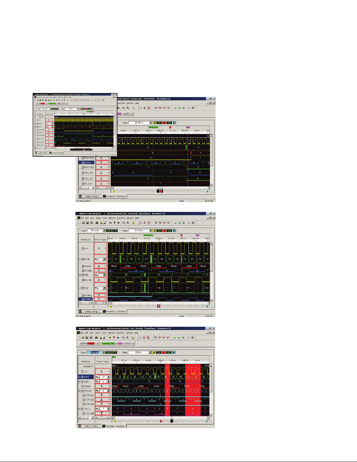
Get instant insights into your design
..............................................................................
Your Agilent logic analyzer helps you expose problems quickly and easily,
so you can spend your time designing a solution. The instrument’s navigation,
data view and analysis features provide instant insights into your system’s
operation.
Trace Navigation
Traverse the trace quickly using
Beginning, Trigger and End icons.
Scroll rapidly through the measurement
using the dedicated knobs or GUI scroll
bars.
Zoom in and out to get just the view
you want.
Receive instant feedback on the exact
position of the display data relative to
the entire trace.
Data View
Check the activity indicators to see
if your target is alive.
Individually color and size the
signals/buses to highlight and
differentiate areas of interest.
View data in a format you understand—
binary, hex, decimal, ASCII, or user
defined symbols.
Compare signals/buses directly with
the Overlay feature.
Analysis Tools
Find meaning in the most complex data
with Find and Filter tools.
Gain quick insights into event frequency
by using the color selection in the Filter
tool.
Simultaneously view bus values and
chart bus activity over time.
www.agilent.com/find/digitaldesign
9
Page 10

Specifications and
370 ohms
1.5pF 7.4pF
100K
ohm
GROUND
Characteristics
Agilent Technologies
1680 and 1690 series
Equivalent Probe Load for the 01650-61608
General-Purpose Lead Set.
Channels 136, 102, 68, 34
State Analysis
State speed 200 MHz
State memory depth Standard: 256K
Deep: 1M
Minimum state clock pulse width 1.2ns
Time tag resolution 4ns or +/-0.1%, whichever is greater
Maximum time count between states 17 seconds
State clock/qualifiers 4 (2 on 34 channel models)
Minimum master-to-master clock time 5.0 ns
Minimum master-to-slave clock time 2.0 ns
Minimum slave-to-master clock time 5.0 ns
Setup/hold time 2.5 ns window adjustable from 4.5/-2 ns
(Single clock, single edge) to -2.0/4.5 ns in 100 ps increments per channel
Setup/hold time 3.0 ns window adjustable from 5.0/-2 ns
(Multiple clock, multi edge) to -1.5/4.5 ns in 100 ps increments per channel
Timing Analysis
Timing speed 400/800 MHz (full/half channel)
Timing memory depth Standard: 512K/1M (full/half channel)
Deep: 2M/4M (full/half channel)
Sample period, full channels 2.5 ns to 1 ms
Sample period, half channels 1.25 ns
Sample period accuracy +/-(0.01% of Sample period +/- 100 ps)
Channel-to-channel skew <1.5ns typical
Time interval accuracy +/-(Sample period accuracy + channel-to-channel
skew +0.01% of reading)
Triggering
Sequencer speed 200 MHz
Maximum occurrence counter 16,777,215
Range width 32 bits
Timer value range 100 ns to 5497 seconds
Timer resolution 5 ns
Timer accuracy 10 ns +/-0.01% of setting
Trigger resources 16 patterns
15 ranges
Timers 3 (136 channels)
2 (102 channels)
1 (68 channels)
0 (34 channels)
Occurrence counters 1 per sequence level
Trigger sequence levels 16
Trigger in arms logic analyzer 15 ns typical delay
Trigger to Trigger out 150 ns typical delay
Probes
Input resistance 100 K Ohms +/- 2%
Parasitic tip capacitance 1.5 pf
Maximum input voltage +/- 40V peak
Minimum voltage swing 500 mV p-p
Threshold range -6V to + 6V in 10 mV increments
Threshold accuracy +/-(65mV + 1.5% of setting)
10
Page 11

A family of high performance logic analyzers
at an affordable price
..............................................................................
Agilent’s Windows-based logic analyzers are designed to match your work style, application
and budget. In all, 16 models offer a variety of channel counts and memory depths in benchtop
or PC-hosted form factors. Each provides the same performance, core features and functionality
in a small footprint that saves valuable workspace.
Measurement Modes Memory Depths
State: 200 MHz Standard: 256 K
Timing: 400/800 MHz Standard: 512 K/1 M (full/half channel)
(full/half channel) Deep: 2 M/4 M (full/half channel)
Deep: 1 M
Transitional Timing: 200 MHz Standard: 256 K
1680 series
• Self-contained benchtop instrument
• Large, built-in, 12.1-inch color display
• Cable flexibility—front or back
• Front panel knobs and hot keys
• Includes a mouse, mini keyboard, front
panel cover and accessory pouch
Deep: 1 M
1690 series
• PC-hosted instrument
• Uses PC display
• Cable connection from the front
• Small footprint, lowest price
• Includes desktop IEEE 1394 PCI card
and cable, laptop IEEE 1394 cable and
accessory pouch
..............................................................................
Selecting a logic analyzer to meet your application and budget is as easy as 1, 2, 3
Choose the
12
form factor
Benchtop 1680 Series Standard Memory 1680A 1681A 1682A 1683A
PC-Hosted 1690 Series Standard Memory 1690A 1691A 1692A 1693A
Choose the
memory depth
Deep Memory 1680AD 1681AD 1682AD 1683AD
Deep Memory 1690AD 1691AD 1692AD 1693AD
Select the channel count
3
136 102 68 34
Channels Channels Channels Channels
11
Page 12

Solve critical digital design
problems faster.
Get there today:
www.agilent.com/find/digitaldesign
Agilent Technologies’ Test and Measurement
Support, Services, and Assistance
Agilent Technologies aims to maximize the value
you receive, while minimizing your risk and problems. We strive to ensure that you get the test and
measurement capabilities you paid for and obtain
the support you need. Our extensive support
resources and services can help you choose the
right Agilent products for your applications and
apply them successfully. Every instrument and system we sell has a global warranty. Support is available for at least five years beyond the production
life of the product. Two concepts underlie Agilent's
overall support policy: "Our Promise" and "Your
Advantage."
Our Promise
Our Promise means your Agilent test and measurement equipment will meet its advertised performance and functionality. When you are choosing
new equipment, we will help you with product
information, including realistic performance specifications and practical recommendations from experienced test engineers. When you use Agilent
equipment, we can verify that it works properly,
help with product operation, and provide basic
measurement assistance for the use of specified
capabilities, at no extra cost upon request. Many
self-help tools are available.
Create a quality connection to your target system
Agilent provides probing solutions that deliver a solid electrical and mechanical
connection to your target, no matter what mix of chip packages, test ports and
probes your application requires. The 1680 and 1690 series logic analyzers also
provide inverse assembly support for many of today’s leading processors and buses.
The following literature provides information on probing and specific processor/bus
solutions for the 1680 and 1690 series analyzers. For copies of this literature, contact
your Agilent representative or visit: www.agilent.com/find/digitaldesign
Agilent Pub.
Publication Description Number
Probing Solutions for Product Overview 5968-4632E
Agilent Logic Analysis Systems
Processor and Bus Support for Configuration Guide 5966-4365E
Agilent Technologies Logic Analyzers
Your Advantage
Your Advantage means that Agilent offers a wide
range of additional expert test and measurement
services, which you can purchase according to your
unique technical and business needs. Solve problems efficiently and gain a competitive edge by contracting with us for calibration, extra-cost upgrades,
out-of-warranty repairs, and on-site education and
training, as well as design, system integration, project management, and other professional engineering services. Experienced Agilent engineers and
technicians worldwide can help you maximize your
productivity, optimize the return on investment of
your Agilent instruments and systems, and obtain
dependable measurement accuracy for the life of
those products.
For more assistance with your test and
measurement needs or to find your local
Agilent office go to
www.agilent.com/find/assist
Product specifications and descriptions in this
document subject to change without notice.
© Agilent Technologies, Inc. 2001
Printed in USA June 29, 2001
Intel is a U.S. registered trademark and Celeron
is a U.S. trademark of Intel Corporation.
Microsoft and Windows are U.S. registered
trademarks of Microsoft Corporation.
5988-2675EN
 Loading...