

Page 1

Help Volume
© 2000-2001 Agilent Technologies Inc. All rights reserved.
Instrument: Agilent
Technologies 16720A 300 M
Vectors/s Pattern Generator
Page 2

Using the Agilent Technologies 16720A Pattern Generator
The Agilent 16720A Pattern Generator is used by digital design teams
to emulate digital signals in circuits under development. The pattern
generator can take the place of missing devices, or can act as a
stimulus to functionally test prototypes.
Getting Started • “Overview of the Agilent Technologies 16720A Pattern Generator” on
page 10
• “A Beginner's Exercise” on page 17
Creating the Program • “Building an Initialization Sequence” on page 21
• “Building a Main Sequence” on page 23
• “Building a User Macro” on page 25
• “Importing Agilent 16522A ASCII Files” on page 28
• “Importing Agilent 16720A PattGen Binary Files” on page 39
• “Importing System Data Files” on page 58
• “Loading and Saving Pattern Generator Configurations” on page 61
See Also “Selecting the Correct Probe Pod” on page 62
“Connecting the Probe Pods” on page 71
“Editing Sequences” on page 73
“Working with Instruction Types” on page 78
“Working with Labels and Pods” on page 85
“Working with Macro Parameters” on page 98
“Working with Automatic Pattern Fills” on page 101
2
Page 3

Using the Agilent Technologies 16720A Pattern Generator
“Printing the Pattern Generator Window” on page 108
“Printing Vector Sequences to a File” on page 109
“Viewing a Compiled Sequence” on page 116
Using the Intermodule Window (see the Agilent Technologies 16700A/BSeries Logic Analysis System help volume)
“Key Characteristics” on page 111
Main System Help (see the Agilent Technologies 16700A/B-Series Logic
Analysis System help volume)
Glossary of Terms (see page 117)
3
Page 4

Using the Agilent Technologies 16720A Pattern Generator
4
Page 5

Contents
Using the Agilent Technologies 16720A Pattern Generator
1 Using the Agilent Technologies 16720A Pattern Generator
Overview of the Agilent Technologies 16720A Pattern Generator 10
Mapping Probe Pods to the Interface 11
Vector Output Mode 12
Clock Source 13
Building a Sequence of Test Vectors 15
Running the Pattern Generator 16
A Beginner’s Exercise 17
Configure Format 17
Configure Sequence 18
Set up the Workspace 19
View the Results 19
Building an Initialization Sequence 21
Building a Main Sequence 23
Building a User Macro 25
Importing Agilent 16522A ASCII Files 28
Creating an ASCII File 30
ASCII Disk File Identifier 32
ASCII File Commands 32
Importing Agilent 16720A PattGen Binary Files 39
Creating a PattGen Binary File 40
Binary File Commands 42
5
Page 6

Contents
Importing System Data Files 58
Data Sets 59
Data Set Labels 59
Data Set Range 60
Loading and Saving Pattern Generator Configurations 61
Selecting the Correct Probe Pod 62
Data Pod Descriptions 63
Clock Pod Descriptions 67
Connecting the Probe Pods 71
Editing Sequences 73
Cutting, Copying, Pasting, and Deleting Sequence Lines 73
Deleting Sequence Lines 74
Inserting Blank Sequence Lines 75
Go to a Line Number 76
Positioning the Sequence 76
Using Ditto " values 77
Working with Instruction Types 78
The Break Instruction 79
The Signal IMB Instruction 79
The Wait IMB Event Instruction 80
The Wait External Event Instruction 80
The User Macro Instruction 81
The Repeat Loop Instruction 82
6
Page 7

Contents
Working with Labels and Pods 85
Creating and Inserting New Labels 86
Deleting Labels 87
Inserting Pre-assigned Labels 88
Renaming Existing Labels 88
Reordering a Label’s Pod Bits 89
Turning Labels On/Off 89
Clearing Format Labels 90
Searching for Labels 90
Swap Pods 90
Clear Pods 91
Assigning Bits to a Label 91
Label Polarity 92
Finding a label 92
Replace Labels 93
Appending Labels 94
Insert All Labels 95
Delete All Labels 95
Setting the Label Font Size 95
Adjusting Column Width 96
Setting Column Color 96
Setting the Numeric Base 97
Rearranging the Label Order 97
Working with Macro Parameters 98
Turning Parameters On 98
Inserting Parameters into a Macro 99
Assigning Parameter Values 99
Removing Parameters from a Macro 100
Working with Automatic Pattern Fills 101
Generating a Fixed Pattern Fill 101
Generating a Count Pattern Fill 102
Generating a Rotate Pattern Fill 103
Generating a Toggle Pattern Fill 105
Generating a Random Pattern Fill 106
7
Page 8

Contents
Printing the Pattern Generator Window 108
Printing Vector Sequences to a File 109
Key Characteristics 111
Automatic Cursor Wrap 113
Recalling Macros 114
Copying Macros 115
Viewing a Compiled Sequence 116
Glossary
Index
8
Page 9

1
Using the Agilent Technologies 16720A Pattern Generator
9
Page 10

Chapter 1: Using the Agilent Technologies 16720A Pattern Generator
Overview of the Agilent Technologies 16720A Pattern Generator
Overview of the Agilent Technologies 16720A
Pattern Generator
Description of the Agilent 16720A Pattern Generator
The Agilent 16720A Pattern Generator is a tool that generates digital
signals. It is used in applications that require an external source to
simulate digital circuitry or generate digital signals for functionally
testing prototype hardware.
Combined with the analog and digital measurement capabilities of the
logic analysis system, you have a tightly integrated solution to your
digital stimulus and response measurement needs.
A Conceptual Measurement Example
The exact output pattern, clock type and speed, and number of
required signals depends on your specific application. How you
configure the pattern generator and what kind of signal generation
sequence you create will vary. However, from a procedural standpoint,
the steps are the same each time to set up, create a sequence, and run
the pattern generator.
1. Select the probing (see page 62) that is compatible with your target
circuit.
2. Set the Vector Output mode (see page 12) and the Clock Source (see
page 13) parameters.
3. Connect the probes (see page 71) to your circuit and map the probe
channels (see page 11) into the interface of the pattern generator.
4. Build a sequence of test vectors (see page 15) to generate the desired
output signals.
5. Run (see page 16) the pattern generator and measure the active target
circuit or prototype for the desired results.
Re-using Pattern Generator Programs
After you set up a pattern generator configuration, you may want to
store it away so you can use it again. Perhaps you want to create a set
10
Page 11

Chapter 1: Using the Agilent Technologies 16720A Pattern Generator
Overview of the Agilent Technologies 16720A Pattern Generator
of test routines or circuit simulators. There are three ways to handle
re-usable configurations.
• You can reload previously saved (see page 61) pattern generator
configurations.
• You can import an Agilent 16522A ASCII file (see page 28) (can only be
used for vector sets <= 1048576 vectors)
• You can import a Agilent 16720A PattGen Binary file (see page 39) (must
be used for vector sets >1048576 vectors)
See Also “A Beginner's Exercise” on page 17
“Key Characteristics” on page 111
Mapping Probe Pods to the Interface
While the probes make the physical connection to your target circuit, a
software connection is also made within the interface which routes
generated signals to the proper probe output lines. This software
connection is done within the Format tab and is called mapping.
The mapping process consists of logically grouping output signals that
have a similar purpose to a label (see page 85) with a unique name. To
add to or delete signals from a group, you simply turn On/Off the bits
(see page 91) beside the label.
Example
This example shows eight channels (or bits) on probe pod 1 mapped to
two labels in the interface. Bits 0-3 are assigned to label Bus_A, and
bits 4-7 are assigned to label Bus_B. When a bit is assigned, an asterisk
"*" appears in the bit assignment field, verifying the software
connection.
11
Page 12

Chapter 1: Using the Agilent Technologies 16720A Pattern Generator
Overview of the Agilent Technologies 16720A Pattern Generator
NOTE: After you set up your first measurement, use the ribbon cable ID clips to mark
the data cable numbers for future reference.
Vector Output Mode
The Vector Output Mode determines the channel width, available pods,
and the frequency range for both the internal and external clock. The
choice you make may be determined by trade-offs between clock speed
and channel width.
Because the output mode affects clock frequency ranges, available
pods, and channel width, keep your mode selection in mind when
designing the circuit’s hardware interface and when mapping probe
connections between the test circuit and the labels of the pattern
generator.
This table shows the difference between the Full-Channel 180 MBits/s
mode and the Half-Channel 300 MBits/s mode.
12
Page 13

Chapter 1: Using the Agilent Technologies 16720A Pattern Generator
Overview of the Agilent Technologies 16720A Pattern Generator
Clock Source
The Clock Source field toggles between internal and external. The
internal clock source is supplied by the pattern generator and controls
the frequency used to output the vectors to the system under test. The
external clock is provided by the user or the system under test, and is
input to the pattern generator through the CLK IN probe of a clock
pod.
An advantage of using an external clock is that you synchronize the
vector output of the pattern generator to the system under test. No
matter which clock source is used, vectors are always output on the
rising edge of the clock.
Internal Clock Source
Use an internal clock source when you want to have control over the
frequency of the output vectors and it is not important for the output
vectors to be synchronized to the system under test.
You select clock frequencies in steps of 1. If you use the keypad to
select a value between the step intervals, the value is rounded to the
nearest interval.
13
Page 14

Chapter 1: Using the Agilent Technologies 16720A Pattern Generator
Overview of the Agilent Technologies 16720A Pattern Generator
NOTE: If you use the keypad to change the the clock frequency value, you must press
the Enter key to register the new value. You are not required to type "Hz", you
may use only a metric prefix or you may enter a floating point number, i.e.
"50M" and "5e7" will both be displayed as "50MHz" after you select enter. You
may also enter the value as a period, i.e. "20n" and "2e-8" will both be
displayed as "50MHz".
The minimum clock period available with Vector Output Mode at Full
Channel 180Mbit/s is 1MHz. Maximum clock frequency for Full Channel
Mode is 180MHz. The minimum clock frequency available with Vector
Output Mode at Half Channel 300Mbit/s is 1MHz. Maximum clock
frequency for Half Channel Mode is 300MHz.
External Clock Source
Use an external clock source when you want to synchronize the
frequency of the output vectors to the system under test. With this
mode selected, you do not have direct control over the frequency of
the output vectors. Output vector frequency will be the same as the
external clock.
When using an external clock source the maximum clock period for the
Vector Output Mode at Full Channel 180Mbit/s is 180 MHz. The
maximum clock period for the Vector Output Mode at Half Channel
300Mbit/s is 300 MHz.
CAUTION: If the external clock is faster than the maximum period, the Agilent 16720A
will produce erroneous output vectors.
Clock Out Delay
The clock out delay setting lets you position the output clock with
respect to the data. The zero setting is uncalibrated and should be
measured to determine the initial position with respect to the data.
14
Page 15

Chapter 1: Using the Agilent Technologies 16720A Pattern Generator
Overview of the Agilent Technologies 16720A Pattern Generator
Each numerical change of one on the counter results in an approximate
change of 500 ps.
Building a Sequence of Test Vectors
Test vectors determine the pattern output at each clock cycle. Test
vectors are positioned in a list called a sequence. When a sequence is
run (see page 16), the list of vectors is executed in order of first vector
to last vector. Vectors are always output on the rising edge of the clock.
In every pattern generator application, you have two sequences. An
INIT SEQUENCE (initialization sequence) is used to place your circuit
or subsystem in a known state. The initialization sequence is followed
by the MAIN SEQUENCE. The main sequence is used for the actual
pattern generation that stimulates your circuit under test. The INIT
sequence is only run once, while the MAIN sequence loops if you select
a repetitive run.
Using Hardware and Software Instructions
In addition to test vectors, both INIT and MAIN sequences can include
predefined instruction (see page 78) elements. Instructions can create
Breaks, Loops, and Wait, and can even signal the Intermodule Bus. The
most useful instruction is "User Macro". With a User Macro instruction,
you can create reusable sequences that accept parameters. This
flexibility is very useful in prototype turn-on and environmental
testing.
For more information on INIT and MAIN sequences and how to create
them, see the following topics.
“Building an Initialization Sequence” on page 21
“Building a Main Sequence” on page 23
“Building a User Macro” on page 25
“Working with Instruction Types” on page 78
15
Page 16

Chapter 1: Using the Agilent Technologies 16720A Pattern Generator
Overview of the Agilent Technologies 16720A Pattern Generator
Running the Pattern Generator
If you are not changing the run options, simply select the Run icon to
run a measurement. Select the Stop icon to stop a measurement.
See Also “What Happens when Run is Selected” on page 16
“What Happens when Stop is Selected” on page 16
What Happens when Run is Selected
In single run mode, the vectors are output from the first vector in the
initialization sequence to the last vector of the main sequence. The last
vector of the main sequence will be held at the outputs until you run
again.
In repetitive run mode, the vectors in the initialization sequence will be
output from first to last, one time, then the main sequence will
repetitively output the vectors in that sequence until you select the
Stop icon.
What Happens when Stop is Selected
When the pattern generator acknowledges stop, the vector currently
being output will be held at the outputs until you run again.
16
Page 17

Chapter 1: Using the Agilent Technologies 16720A Pattern Generator
A Beginner’s Exercise
A Beginner’s Exercise
This exercise begins with the pattern generator Format tab active. If it
is not active, select Format in the pattern generator window now.
In this exercise, you will create a label with eight output channels
assigned to it. You will then create a "Walking Ones" output pattern
using one of the automatic pattern fill functions.
NOTE: This exercise does NOT require you to connect the probes or view the output.
The intent of this exercise is to give you practice configuring the pattern
generator interface. A timing analyzer display of the results is furnished for
you.
1. Configure Format (see page 17) with a label called "Walk1" and all eight
bits of Pod 6 assigned.
2. Select Sequence.
3. Configure Sequence (see page 18) with a Walking Ones sequence.
4. Set up the Workspace. (see page 19)
5. View the results. (see page 19)
Configure Format
1. In the pattern generator’s Format area, select the label Label1, then select
Rename. In the Rename dialog, enter "Walk1", then select OK.
2. Select the bit assignment field under Pod 6 and select the menu item with
all eight bits set to "*" (on).
17
Page 18

Chapter 1: Using the Agilent Technologies 16720A Pattern Generator
A Beginner’s Exercise
Configure Sequence
1. In the pattern generator’s Sequence window, select Hex and set the
numeric base to Binary.
2. Select the first sequence line. This positions the cursor.
3. Select Rotate, and configure the Rotate Pattern Fill dialog as shown. Select
Fill.
4. Select Close.
18
Page 19

Chapter 1: Using the Agilent Technologies 16720A Pattern Generator
A Beginner’s Exercise
Set up the Workspace
1. Open the system Workspace window.
2. Drag and drop a waveform icon onto the pattern generator icon.
3. Select the waveform icon, then select Display.
4. Select the Run icon.
View the Results
1. Select Walk 1 all in the waveform display, then select Expand.
2. Set the Samples/div to 1.
19
Page 20

Chapter 1: Using the Agilent Technologies 16720A Pattern Generator
A Beginner’s Exercise
20
Page 21

Chapter 1: Using the Agilent Technologies 16720A Pattern Generator
Building an Initialization Sequence
Building an Initialization Sequence
The initialization (INIT) sequence is the first of two vector sequences
that appear in the Sequence display. Use the INIT sequence to put the
circuit or subsystem into a known starting condition. You can also use
the INIT sequence to arm a logic analyzer or oscilloscope with the
Signal IMB instruction to begin a measurement when the MAIN
sequence begins. If you leave the INIT sequence empty, it will be
ignored.
What Happens when Run is Selected
In single run mode, the vectors are output from the first vector in the
initialization sequence to the last vector of the main sequence. The last
vector of the main sequence will be held at the outputs until you
execute run again.
In repetitive run mode, the vectors in the initialization sequence will be
output from first to last, one time, then the main sequence will
repetitively output the vectors in that sequence until you select the
Stop icon.
Building the INIT Sequence
The INIT sequence can contain hardware and software instructions
(see page 78) as well as vector data. However, instructions are not
allowed on the first two vector lines.
1. Select the Sequence tab, then select INIT START.
2. Select Insert After, then select Vector.
3. Repeat for each new vector line you want to insert.
4. Select the left-most character in the new vector line.
5. Select Edit.
6. Enter in the desired vector data. As you enter the information, the default
cursor wrap (see page 113) setting will roll the cursor left-to-right and top
line to bottom line.
21
Page 22

Chapter 1: Using the Agilent Technologies 16720A Pattern Generator
Building an Initialization Sequence
7. Optional - If applicable, insert an instruction (see page 78) instead of
entering vector data.
See Also “Working with Labels and Pods” on page 85
“Editing Sequences” on page 73
“Working with Instruction Types” on page 78
“Building a User Macro” on page 25
“Automatic Cursor Wrap” on page 113
22
Page 23

Chapter 1: Using the Agilent Technologies 16720A Pattern Generator
Building a Main Sequence
Building a Main Sequence
The MAIN sequence is the second of two vector sequences that appear
in Sequence. Use the MAIN sequence as the primary signal generation
sequence. The MAIN sequence must contain at least two vectors to
output.
What Happens when Run is Selected
In single run mode, the vectors are output from the first vector in the
initialization sequence to the last vector of the main sequence. The last
vector of the main sequence will be held at the outputs until you select
run again.
In repetitive run mode, the vectors in the initialization sequence will be
output from first to last, one time, then the main sequence will
repetitively output the vectors in that sequence until you select the
Stop icon.
Building the Main Sequence
The MAIN sequence can contain hardware and software instructions
(see page 78) as well as vector data. However, instructions are not
allowed on the first two vector lines or the last vector line.
1. Select the Sequence tab, then select MAIN START.
2. Select Insert After, then select Vector.
3. Repeat for each new vector line you want to insert.
4. Select the left-most character in the new vector line.
5. Select Edit.
6. Enter in the desired vector data. As you enter the information, the default
cursor wrap (see page 113) setting will roll the cursor left-to-right and top
line to bottom line.
7. Optional - If applicable, insert an instruction (see page 78) instead of
entering vector data.
23
Page 24

Chapter 1: Using the Agilent Technologies 16720A Pattern Generator
Building a Main Sequence
See Also “Working with Labels and Pods” on page 85
“Editing Sequences” on page 73
“Working with Instruction Types” on page 78
“Building a User Macro” on page 25
“Automatic Cursor Wrap” on page 113
24
Page 25

Chapter 1: Using the Agilent Technologies 16720A Pattern Generator
Building a User Macro
Building a User Macro
A User Macro is a vector sequence defined by a custom name, then
inserted by name into a sequence wherever the macro is needed.
Macros may be inserted into the INIT or MAIN sequences of the vectors
in Sequence, or into other macros. Using macros gives you the benefit
of keeping INIT or MAIN sequences generic. By simply interchanging
macros, you change the pattern generator output.
NOTE: Care should be taken to avoid infinite loops. For example, if macro 0 calls
macro 1, and macro 1 calls macro 0, this will cause an infinite loop.
Macros can also accept parameters (see page 98). A major benefit in
using parameters is that you keep a macro’s functionality generic and
still direct specific action identified by parameters. Think of a
parameter as the only part of a macro that changes as the macro is
reused. Each macro can accept a maximum of 10 unique parameters.
Typically, you create a macro first under the Macro tab, then insert it
into sequences under the Sequence tab. You can create 100 different
macros for use in one or more pattern generator sequences.
Differences between User Macros and the INIT and MAIN sequences
are that macros cannot use any instruction that interacts with the
intermodule bus (IMB). The reason is that these instructions can only
be included once into the sequence. Since macros may be called as
many times as desired, allowing these instructions within macros
would violate this restriction. You remove macros from sequences by
using the Delete Line(s) function.
Creating the Macro
A macro sequence can contain hardware and software instructions
(see page 78) as well as vector data. However, instructions are not
allowed on the first vector line.
1. In Macro, recall (see page 114) the macro that you want to create.
2. Select MACRO START.
3. Select Insert After, then select Vector.
25
Page 26

Chapter 1: Using the Agilent Technologies 16720A Pattern Generator
Building a User Macro
4. Repeat for each new vector line you want to insert.
5. Select left-most character in the new vector line.
6. Enter in the desired vector data. As you enter the information, the default
cursor wrap (see page 113) setting will roll the cursor left-to-right and top
line to bottom line.
7. Optional - Insert an instruction (see page 78) instead of entering vector
data.
8. Enter in a name for the new macro.
9. Optional - Select Parameters and turn on any parameters you plan to use.
Inserting the Macro
1. In Sequence or Macro, select the vector line directly above where you
want to insert the User Macro instruction.
2. Select Insert After, then select User Macro.
3. Select the User Macro instruction.
4. From the Macro Selection dialog that appears, select the desired macro
name you want to insert.
5. Select OK.
26
Page 27

Chapter 1: Using the Agilent Technologies 16720A Pattern Generator
Building a User Macro
NOTE: See The User Macro Instruction (see page 81) for restrictions on User Macro
instruction usage.
See Also “Recalling Macros” on page 114
“Copying Macros” on page 115
“Working with Macro Parameters” on page 98
“Working with Instruction Types” on page 78
“Editing Sequences” on page 73
“Working with Labels and Pods” on page 85
27
Page 28

Chapter 1: Using the Agilent Technologies 16720A Pattern Generator
Importing Agilent 16522A ASCII Files
Importing Agilent 16522A ASCII Files
You can create an ASCII text file and import it as a complete pattern
generator program. In general, the ASCII file consists of a block of
setup information, a block of label and channel information, and a block
of pattern generator vector data. The file must be saved in ASCII
format and organized as shown in step 1 of the procedure below.
1. Create the ASCII file (see page 30) in a text editor.
2. Save the file as Te x t On l y or ASCII Format in a directory on your
analyzer’s hard drive.
3. In the Sequence menu bar, select File, then Import 16522A ASCII File.
See the caution below.
4. From the file selection dialog that appears, select the desired path and
ASCII file name.
5. Select Import.
CAUTION: Importing an Agilent 16522A ASCII file causes all current Format and
Sequence information to be overwritten. Be sure to save the pattern generator
configuration before you begin the import process.
NOTE: Importing a 1048576 line 16522A ASCII file may take approximately two
minutes. If a 1048576 sequence is in memory when you begin an import, it
may take up to a minute to clear the current data and up to two minutes to
import the new data.
28
Page 29

Chapter 1: Using the Agilent Technologies 16720A Pattern Generator
Importing Agilent 16522A ASCII Files
This figure shows Format after the ASCII file example shown in step 1
was imported.
29
Page 30

Chapter 1: Using the Agilent Technologies 16720A Pattern Generator
Importing Agilent 16522A ASCII Files
Creating an ASCII File
You can create an ASCII file using any Windows, MS-DOS, or UNIX text
editor. An ASCII file consists of a file identifier and three blocks of
information. Each block must follow the specified order.
• ASCII 000000 - required file identifier ("ASCII" followed by 5 spaces and
6 zeros).
ASCDown - optional. Retained for backwards compatibility.
• 1st block (optional)
FORMat - clock, channel mode, and delay information.
• 2nd block
LABel - names and number of channels.
• 3rd block
VECTor - vector data and Repeat indicators.
File Requirements and Precautions
• The file must contain only specified pattern generator commands (see
page 32), and in the order and format shown in the example below.
• The file must be saved in "ASCII" or "text only" format.
• Vector data is assumed to be entirely hexadecimal base.
• No pattern generator instructions are allowed in the data.
• No pattern generator macros are defined or invoked in the data.
• All labels consist of adjacent bits.
• The file must end with a line termination character (line feed "<lf>" or a
carriage return and line feed "<CR><lf>".
• Comments can be included after the first line (ASCII 000000). Comments
begin with a slash '/' and terminate at the end of the line.
30
Page 31

Chapter 1: Using the Agilent Technologies 16720A Pattern Generator
Importing Agilent 16522A ASCII Files
ASCII File Example
NOTE: In this example, the underlined links are added for documentation purposes
only, and would NOT be part of an actual disk file’s text. Line feeds "<lf>" are
shown for example purposes only, and depending on the computer and text
editor used, could actually be a carriage return followed by a line feed
"<CR><lf>".
ASCII 000000 (see page 32)<lf>
/
/ This is a test of the ascii file
/
ASCDown (see page 33)<lf>
FORMat:MODE FULL (see page 36)<lf>
FORMat:CLOCk INTernal, 10E-9 (see page 36)<lf>
LABel LAB1,8 (see page 33)<lf>
LABel DATA,8<lf>
LABel TEST,9<lf>
LABel CLK,3<lf>
LABel BIG,12<lf>
/*
/* This is the beginning of the vector part
/*
VECTor (see page 34)<lf>
12 34 056 7 89A<lf> / Some vectors
0 22 007 0 FFF<lf>
A0 33 000 1 111<lf> /* Some more vectors */
*M<lf>
92 6F 000 1 FF0<lf>
CA CA 000 1 00F<lf> // Even more vectors
*R 3<lf>
00 10 011 0 ABC<lf>
NOTE: The LABel sequence specified in the 8th through 12th lines results in a
specific bit assignment. A different ordering of the LABel commands would
give a different ordering to the bits.
31
Page 32

Chapter 1: Using the Agilent Technologies 16720A Pattern Generator
Importing Agilent 16522A ASCII Files
ASCII Disk File Identifier
The first line of a disk file must contain the text string "ASCII
000000". It consists of the text "ASCII" followed by 5 blanks, then 6
zeros. The purpose of this string is to uniquely identify the file as an
ASCII disk file.
Example
ASCII File Commands
The following commands are used in the ASCII file to configure
Sequence and Format. Commands are not case sensitive. Lowercase
letters in an illustrated command simply show the long and short form
difference.
The uppercase letters of the command show the mandatory portions of
each command.
Commands
“ASCDown Command” on page 33
FORMat Commands
MODe (see page 36)
CLOCk (see page 36)
32
Page 33

Chapter 1: Using the Agilent Technologies 16720A Pattern Generator
Importing Agilent 16522A ASCII Files
DELay (see page 37)
ASCII Disk File Indentifier (see page 32)
“LABel Command” on page 33
“VECTor Command” on page 34
ASCDown Command
The ASCDown command was formerly used to signal the start of an
ASCII file load. It causes the current pattern generator label and
sequence structures to be cleared and reset to a default state. The
Agilent 16720A pattern generator now does this automatically.
Example
LABel Command
The LABel command is a special means of specifying labels for use by
an ASCII file. The label bits are assigned from most to least significant
bits across the output pods. You must specify the label string
(quotation marks on the string are optional) and the width of the field.
The label base defaults to hexadecimal. There are a maximum of 126
labels. No label may be more than 32 bits wide. If a label is too wide
(too many bits) for the remaining unused pattern generator bits, it will
be discarded.
Command Syntax
LABel <name_str>,<width>
33
Page 34

Chapter 1: Using the Agilent Technologies 16720A Pattern Generator
Importing Agilent 16522A ASCII Files
<name_str> = label string a maximum of 20 characters in length.
<width> = integer number of bits in the label (1 through 32).
Example
VECTor Command
The VECTor command is used after the end of the header/setup
commands to signal the start of the actual pattern generator data in an
ASCII file. No data is allowed in the same line as the VECTor command.
Example
Vector Data
The data portion of the ASCII file is an array of hexadecimal data fields.
Each row of the array corresponds to a single line of the main program.
Each column of the array corresponds to a single label as defined under
34
Page 35

Chapter 1: Using the Agilent Technologies 16720A Pattern Generator
Importing Agilent 16522A ASCII Files
the pattern generator Format tab.
Data fields are separated by one or more blank characters. A line
termination (line feed or carriage return + line feed) signals the end of
a line and the start of a new line. If a data field has more data than the
label width would indicate, only the least significant bits of the data
field are used. If there are more data fields in a row than there are
labels, the extra data fields (last data fields in the row) are ignored. If
there are fewer data fields in a row than there are labels, the data for
the extra (right-most) labels will be zero.
The MAIN sequence must have at least two data lines. In the ASCII
data file, a row consisting of only "*M" signals the start of the MAIN
sequence. If there is to be no data in the INIT sequence, the first row of
the file after the VECTor command must be "*M". Note that the
quotation marks in "*M" are not really in the file.
CAUTION: Any character that is not a valid hexadecimal digit (that is, 0 through 9, or
upper/lower case A through F) are ignored and treated as field separators.
This could cause problems if a mistyped character appears in the middle of a
data value. For example, "12R4" will be assigned to two labels as "12" and "4".
Either of the INIT or MAIN sequences can include multiple Repeat
indicators specified by "*R <count>". Note that the quotation marks
around the Repeat indicator are not part of the indicator, and like the
"*M", the "*R <count>" must be located on a separate line.
The Repeat indicator specifies that the previous data vector is repeated
<count> more times, where <count> is a positive integer. The Repeat
indicator must follow a sequence line containing a data vector or
another Repeat indicator. Placing the Repeat indicator after the
VECTor command or the "*M" will cause an error message to appear.
The last data row of the file must end with a line termination character.
The line termination character is the flag to load the data row into the
data structure. Failure to do this will result in the last data row not
being loaded.
The ASCII file import mechanism assumes correctness in the data file
and any header commands. Error handling is basic, and treating
unexpected characters as field separators could create bizarre results
when parsing the file. Error messages point to the line number where
35
Page 36

Chapter 1: Using the Agilent Technologies 16720A Pattern Generator
Importing Agilent 16522A ASCII Files
the parser finds the error.
Serious problems will cause the default main program to be loaded in
an effort to avoid locking up the logic analysis system.
FORMat:MODe Command
The FORMat:MODe command is optional. The existing mode scheme is
used if nothing is specified. FULL channel output mode limits the data
rate to a maximum of 180 MHz, but allows 48 channels per card. HALF
channel output mode allows an output rate of greater than 180 MHz,
but limits the number of channels to 24 per card.
Command Syntax
FORMat:MODe [FULL|HALF]
Example
FORMat:CLOCk Command
The FORMat:CLOCk command is optional. The existing clock scheme
is used if nothing is specified. The CLOCk command specifies the clock
source for the pattern generator.
Command Syntax
FORMat:CLOCk INTernal, <clk_period>
= a real number value that corresponds to the interface selectable
clock period values (example = 5E-9).
36
Page 37

Chapter 1: Using the Agilent Technologies 16720A Pattern Generator
Importing Agilent 16522A ASCII Files
FORMat:CLOCk EXTernal, [LEFifty|GTFifty|GTONe]
[LEFifty] = Less than or equal to 50 MHz.
[GTFifty] = Greater than 50 MHz and less than or equal to 180 MHz.
[GTONe] = Greater than 180 MHz.
NOTE: The maximum clock rate is limited by the channel mode. See FORMat:MODe
(see page 36) command.
Example
FORMat:DELay Command
The FORMat:DELay command is optional. The existing delay scheme is
used if nothing is specified. The DELay command specifies the clock
out delay. The clock out delay setting allows positioning of the clock
with respect to the data. Delay setting range is 0 - 14 with each
increment delaying the clock approximately 500 ps per step.
NOTE: The delay setting that corresponds to zero is uncalibrated. You must measure
it to determine the basic clock/data timing.
Command Syntax
FORMat:DELay <delay_arg>
<delay_arg> = an integer from 0 to 14 with each increment delaying
the clock by approximately 500 ps.
37
Page 38

Chapter 1: Using the Agilent Technologies 16720A Pattern Generator
Importing Agilent 16522A ASCII Files
Example
38
Page 39

Chapter 1: Using the Agilent Technologies 16720A Pattern Generator
Importing Agilent 16720A PattGen Binary Files
Importing Agilent 16720A PattGen Binary Files
You can create a PattGen Binary file and import it as a complete
pattern generator program. In general, the PattGen Binary file consists
of a set of ASCII commands followed by a binary representation of the
vectors. The file must be organized as shown in step 1 of the procedure
below.
1. Create the PattGen Binary file (see page 40).
2. Make the file available in a directory on your logic analysis system hard
drive using the various connectivity methods available from the logic
analysis system. These include FTP, NFS, or PC file sharing.
3. Under the Format tab, select File, then select Import PattGen Binary
File. See the Caution Below
4. From the file selection dialog, select the desired path and PattGen Binary
file name.
5. Select Import.
CAUTION: Importing an Agilent 16720 PattGen Binary file causes all current Format
and Sequence information to be overwritten. Be sure to save the pattern
generator configuration before you begin the import process.
When a PattGen Binary file is loaded, the GUI changes in the following
ways:
• The Sequence and Macro tabs are disabled.
• The Output Mode (full channel/half channel) button is disabled.
• Channel assignments can not be edited.
The reason for each of these changes is the same. When a PattGen
Binary file is loaded, it is loaded directly into the 16720A hardware.
Because PattGen Binary files can be very large there is no internal
representation that can be edited and/or displayed as there is for the
16522A ASCII or System Date files.
Changing among Full and Half channel modes requires memory to be
reloaded. Changing channel assignments or adding labels with channel
39
Page 40

Chapter 1: Using the Agilent Technologies 16720A Pattern Generator
Importing Agilent 16720A PattGen Binary Files
assignments also requires memory to be reloaded.
If you save a configuration after loading a PattGen file, the
configuration will not contain the binary data. You will have to reload
the original PattGen Binary file.
Vectors that are loaded from a PattGen Binary file can be viewed in a
Listing Window attached to the output of the 16720A icon on the
Workspace. The Listing Window displays vectors by reading them from
memory on 16720A card.
You can exit the Binary Mode (where editing is disabled) either by
loading a non-binary file (i.e. 16522A ASCII) or by selecting Enable
Sequence Tab in the File menu. This causes the vectors that were
loaded from the binary file to be replaced by the default vectors, which
are two vectors of all zero values.
Creating a PattGen Binary File
The PattGen Binary is primarily designed for deep (>1048576) vector
sets and the various other formats (i.e. 16522A ASCII) will be used for
shorter sets. The deep vector sets can be generated from tools, such as
Verilog simulators, and translated to PattGen Binary by third party
tools or customer-developed translation utilities. The changes to
vectors, labels, etc. should be made in the tool that originally generated
the vectors (i.e. Verilog).
Example
C/C++ code for generating PattGen Binary is available on the logic
analysis system in the directory /logic/demo/pattgen which contains
these files.
• simple_pg.c- A very simple example of how to generate PattGen Binary.
• simple pgb- The PattGen Binary file created by simple_pg.c
• pattgen.c- A more extensive example with command line options.
• binary_yacc.y- A simple utility that will parse and print PattGen Binary.
40
Page 41

Chapter 1: Using the Agilent Technologies 16720A Pattern Generator
Importing Agilent 16720A PattGen Binary Files
• binary_lex.1- A simple utility that will parse and print PattGen Binary.
• makefile- Rules for building the examples with typical C/C++ compilers.
• ToolDevKit - A directory containing instructions for installing a Workspace
Tool that will generate a PattGen Binary file from vectors captured with a
logic analyzer. See the README file in that directory for details.
• fastReader - A utility that will translate Fast Binary files to PattGen Binary
files. Source code and a .exe file are included. See the README file in that
directory for details.
File Requirements and Precautions
• The file must contain only specified pattern generator commands (see
page 42), and in the order and format shown in the example below.
• The file must be created in binary byte-stream format.
• Vector data must be entirely in binary.
• No pattern generator instructions are allowed in the data.
• No pattern generator macros are defined or invoked in the data.
• Labels may consist of adjacent bits or arbitrarily ordered bits.
• Each ACSII command must end with a line termination character (line
feed "<lf>" or a carriage return and line feed "<CR><lf>"
• Comments can be included after the first command (PGBINARY).
• Comments begin with a slash '/' and terminate at the end of the line.
PattGen Binary Example
NOTE: In this example only the ASCII pattern generator commands are shown. The
binary vector data is not illustrated. This example is available on the logic
analysis system in the file /logic/pattgen/demo/simpe.pgb.
PGBINARY
MODE FULL
CLOCK INTERNAL 5e7
MAIN 0
LABEL Label0 POD 0 [7:0]
LABEL Label1 POD 1 [7:0]
41
Page 42

Chapter 1: Using the Agilent Technologies 16720A Pattern Generator
Importing Agilent 16720A PattGen Binary Files
LABEL Label2 POD 2 [7:0]
LABEL Label3 POD 3 [7:0]
LABEL Label4 POD 4 [7:0]
LABEL Label5 POD 5 [7:0]
WIDTH 6
DEPTH 4096
BEGIN
NOTE: The LABEL sequence specified in the 5th through 10th lines results in a
specific bit assignment. Different POD assignments in those LABEL
commands would give a different ordering to the bits.
PattGen Binary File Identifier
The first line of a PattGen Binary file must contain the text string
"PGBINARY". The purpose of this string is to uniquely identify the file
as a PattGen Binary file.
Example
PGBINARY
MODE FULL
CLOCK INTERNAL 5e7 // 50 MHz
MAIN 0
LABEL Label0 POD 0 [7:0]
LABEL Label1 POD 1 [7:0}
LABEL Label2 POD 2 [7:0]
LABEL Label3 POD 3 [7:0]
LABEL Label4 POD 4 [7:0]
LABEL Label5 POD 5 [7:0]
WIDTH 6
DEPTH 4096
BEGIN
Binary File Commands
The following ASCII commands are used in the PattGen Binary file to
configure Sequence and Format. Commands may be all uppercase or
42
Page 43

Chapter 1: Using the Agilent Technologies 16720A Pattern Generator
Importing Agilent 16720A PattGen Binary Files
all lowercase, but not mixed. Commands may not be abbreviated or
truncated.
Commands
PattGen Binary File Identifier (see page 42)
CLOCK (see page 43)
DELAY (see page 44)
MODE (see page 45)
RMODE (see page 46)
LABEL (see page 46)
ORDER (see page 49)
WIDTH (see page 50)
DEPTH (see page 50)
BREAK (see page 52)
EVENT (see page 52)
WAIT (see page 53)
SIGNAL (see page 54)
MAIN (see page 55)
BEGIN (see page 56)
Binary Data (see page 57)
CLOCK Command
The CLOCK command is optional. The existing clock scheme is used if
nothing is specified. The CLOCK command specifies the clock source
for the pattern generator.
Command Syntax
CLOCK EXTERNAL
Set the clock mode to externally clocked.
43
Page 44

Chapter 1: Using the Agilent Technologies 16720A Pattern Generator
Importing Agilent 16720A PattGen Binary Files
NOTE: The maximum clock rate is limited by the channel mode. See MODE
command.
Example
PGBINARY
MODE FULL
CLOCK INTERNAL 5e7 // 50 MHz
MAIN 0
LABEL Label0 POD 0 [7:0]
LABEL Label1 POD 1 [7:0]
LABEL Label2 POD 2 [7:0]
LABEL Label3 POD 3 [7:0]
LABEL Label4 POD 4 [7:0]
LABEL Label5 POD 5 [7:0]
WIDTH 6
DEPTH 4096
BEGIN
DELAY Command
The DELAY command is optional. The existing delay scheme is used if
nothing is specified. The DELAY command specifies the clock out
delay. The clock out delay setting allows positioning of the clock with
respect to the data. Delay setting range is 0 - 14 with each increment
delaying the clock approximately 500 ps per step.
NOTE: The delay setting that corresponds to zero is uncalibrated. You must measure
it to determine the basic clock/data timing.
Command Syntax
DELAY <delay_arg>
<delay_arg> = an integer from 0 to 14 with each increment delaying
the clock by approximately 500 ps.
Example
PGBINARY
MODE FULL
44
Page 45

Chapter 1: Using the Agilent Technologies 16720A Pattern Generator
Importing Agilent 16720A PattGen Binary Files
CLOCK INTERNAL 5e7 // 50 MHz
DELAY 6
MAIN 0
LABEL Label0 POD 0 [7:0]
LABEL Label1 POD 1 [7:0]
LABEL Label2 POD 2 [7:0]
LABEL Label3 POD 3 [7:0]
LABEL Label4 POD 4 [7:0]
LABEL Label5 POD 5 [7:0]
WIDTH 6
DEPTH 4096
BEGIN
MODE Command
The MODE command is optional. The existing mode scheme is used if
nothing is specified. FULL channel output mode limits the data rate to
a maximum of 180 MHz, but allows 48 channels per card. HALF
channel output mode allows an output rate of up to 300 MHz, but limits
the number of channels to 24 per card.
Command Syntax
MODE [FULL|HALF]
Example
PGBINARY
MODE FULL
CLOCK INTERNAL 5e7 // 50 MHz
MAIN 0
LABEL Label0 POD 0 [7:0]
LABEL Label1 POD 1 [7:0]
LABEL Label2 POD 2 [7:0]
LABEL Label3 POD 3 [7:0]
LABEL Label4 POD 4 [7:0]
LABEL Label5 POD 5 [7:0]
WIDTH 6
DEPTH 4096
BEGIN
45
Page 46

Chapter 1: Using the Agilent Technologies 16720A Pattern Generator
Importing Agilent 16720A PattGen Binary Files
RMODE Command
The RMODE command is optional. The existing run mode scheme is
used if nothing is specified. SINGLE indicates that a run will output the
INIT part followed by the MAIN part one time each. REPETITIVE
indicates that a run will output the INIT part once followed by the
MAIN part repeating until the STOP icon is selected.
Command Syntax
RMODE [SINGLE][REPETITIVE]
Example
PGBINARY
MODE FULL
RMODE SINGLE
CLOCK INTERNAL 5e7 // 50 MHz
MAIN 0
LABEL Label0 POD 0 [7:0]
LABEL Label1 POD 1 [7:0]
LABEL Label2 POD 2 [7:0]
LABEL Label3 POD 3 [7:0]
LABEL Label4 POD 4 [7:0]
LABEL Label5 POD 5 [7:0]
WIDTH 6
DEPTH 4096
BEGIN
LABEL Command
The LABEL command is a special means of specifying labels for use by
a PattGen Binary file. The first <integer> following the POD keyword is
the pod number. Pods are numbered from 0...N where N is the
maximum number pods in a logic analysis system minus 1. In the
16720A the number of pods would be 0...29 in Full channel mode or
0...14 in Half channel mode when five cards are connected as a master
card and four expander cards. The pods are numbered from left to
right. By using index numbers rather than the names they would have
in the logic analysis system (i.e. B6 for Pod 6 in Slot B) the command is
independent of how the logic analysis system is configured. Bit
46
Page 47

Chapter 1: Using the Agilent Technologies 16720A Pattern Generator
Importing Agilent 16720A PattGen Binary Files
assignment are from Most Significant Bit to Least Significant Bit.
Command Syntax
LABEL <name> { POD <integer> { <integer> | [ <integer> : <integer> ]
}}
<name_str> = label string a maximum of 20 characters in length. The
name string must begin with a letter (A-Z, a-z) or underscore (_) and
can be followed by letters, underscores, or digits (0-9). A label may not
be a keyword (see page 48). If you wish to use a keyword as a label,
you may do so by enclosing it in quotes.
<integer> = POD index or bit number.
Example
PGBINARY
MODE FULL
RMODE SINGLE
CLOCK INTERNAL 5e7 // 50 MHz
MAIN 0
LABEL Label0 POD 0 [7:0]
LABEL Label1 POD 1 [7:0]
LABEL Label2 POD 2 [7:0]
LABEL Label3 POD 3 [7:0]
LABEL Label4 POD 4 [7:0]
LABEL Label5 POD 5 [7:0]
WIDTH 6
DEPTH 4096
BEGIN
47
Page 48

Chapter 1: Using the Agilent Technologies 16720A Pattern Generator
Importing Agilent 16720A PattGen Binary Files
Example
PGBINARY
MODE FULL
RMODE SINGLE
CLOCK INTERNAL 5e7 // 50 MHz
MAIN 0
LABEL Select0 POD 0 7
LABEL Select1 POD 0 6
LABEL IN_BUS0 POD 0 [5:2]
LABEL IN_BUS1 POD 0 [1:0] POD 1 [7:6]
LABEL IN_BUS2 POD 1 [5:2]
LABEL IN_BUS3 POD 1 [1:0] POD 2 [7:6]
LABEL OUT_BUS POD 2 [5:2]
WIDTH 7
DEPTH 4096
BEGIN
Keywords
The following are keywords in the PattGen Binary file and may not be
used as labels.
48
Page 49

Chapter 1: Using the Agilent Technologies 16720A Pattern Generator
Importing Agilent 16720A PattGen Binary Files
ORDER Command
The Order command provides an optional means for specifying the
order that data for labels will appear. If the order is not specified it is
assumed to be the order in which labels were defined. If the ORDER
command contains only a subset of the labels that have been defined,
then the subsequent BEGIN command refers only to the labels named
in the ORDER command.
Command Syntax
ORDER { <name_str> }
<name_str> = label string a maximum of 20 characters in length.
Example
PGBINARY
MODE FULL
RMODE SINGLE
CLOCK INTERNAL 5e7 // 50 MHz
MAIN 0
LABEL Label0 POD 0 [7:0]
LABEL Label1 POD 1 [7:0]
LABEL Label2 POD 2 [7:0]
LABEL Label3 POD 3 [7:0]
LABEL Label4 POD 4 [7:0]
LABEL Label5 POD 5 [7:0]
ORDER Label 0 Label1 Label2 Label3 Label4 Label5
WIDTH 6
DEPTH 4096
BEGIN
49
Page 50

Chapter 1: Using the Agilent Technologies 16720A Pattern Generator
Importing Agilent 16720A PattGen Binary Files
WIDTH Command
The WIDTH command defines how wide, in number of bytes, the
binary data will be. The width is determined by summing the size,
rounded up to full bytes, of every label that is defined or named in an
ORDER command. The total number of data bytes in the file must be
(DEPTH * WIDTH). WIDTH must be defined before the binary data
part begins. The binary data part also contains the width. This
redundant information is used as one verification of the binary data.
Command Syntax
WIDTH <integer>
<integer> = number of bytes wide the binary data will be.
Example
PGBINARY
MODE FULL
RMODE SINGLE
CLOCK INTERNAL 5e7 // 50 MHz
MAIN 0
LABEL Label0 POD 0 [7:0]
LABEL Label1 POD 1 [7:0]
LABEL Label2 POD 2 [7:0]
LABEL Label3 POD 3 [7:0]
LABEL Label4 POD 4 [7:0]
LABEL Label5 POD 5 [7:0]
WIDTH 6
DEPTH 4096
BEGIN
DEPTH Command
The DEPTH command defines how may vectors will appear in the
binary data. The total number of bytes in the binary data part of the file
must be (DEPTH * WIDTH). DEPTH must be defined before the binary
data part begins. The binary data part also contains the depth. This
redundant information is used as one verification of the binary data.
The DEPTH has the following restrictions based on the MODE (FULL
50
Page 51

Chapter 1: Using the Agilent Technologies 16720A Pattern Generator
Importing Agilent 16720A PattGen Binary Files
or HALF) that the instrument will be in.
FULL Channel Mode
• INIT part must be an even number of vectors.
• MAIN part must be an even number of vectors.
• Total depth can be no more than 8,388,608.
• Total depth can be no less than 4, 096.
HALF Channel Mode
• INIT part must be a multiple of 4 vectors.
• MAIN part must be a multiple of 4 vectors.
• Total depth can be no more than 16,777,216.
• Total depth can be no less than 4,096.
Command Syntax
DEPTH <integer>
<integer> = number of vectors in the binary data.
Example
PGBINARY
MODE FULL
RMODE SINGLE
CLOCK INTERNAL 5e7 // 50 MHz
MAIN 0
LABEL Label0 POD 0 [7:0]
LABEL Label1 POD 1 [7:0]
LABEL Label2 POD 2 [7:0]
LABEL Label3 POD 3 [7:0]
LABEL Label4 POD 4 [7:0]
LABEL Label5 POD 5 [7:0]
WIDTH 6
DEPTH 4096
BEGIN
51
Page 52

Chapter 1: Using the Agilent Technologies 16720A Pattern Generator
Importing Agilent 16720A PattGen Binary Files
BREAK Command
The BREAK command places a hardware BREAK instruction on a
vector number <integer>. Vectors are numbered from 0 to DEPTH - 1.
Command Syntax
BREAK <integer>
<integer> = the vector where a hardware BREAK instruction is to be
placed.
Example
PGBINARY
MODE FULL
RMODE SINGLE
CLOCK INTERNAL 5e7 // 50 MHz
MAIN 0
LABEL Label0 POD 0 [7:0]
LABEL Label1 POD 1 [7:0]
LABEL Label2 POD 2 [7:0]
LABEL Label3 POD 3 [7:0]
LABEL Label4 POD 4 [7:0]
LABEL Label5 POD 5 [7:0]
BREAK 100
WIDTH 6
DEPTH 4096
BEGIN
NOTE: A BREAK instruction can go on any vector except the first vector or the last
vector. The last vector instruction is used to implement single and repetitive
run modes and is not available for other instructions. Attempting to place an
instruction on or beyond the last vector is an error.
EVENT Command
The EVENT command sets a pattern into one of the four external
event registers. These event registers can be specified in WAIT
instructions. If the pattern is NONE then a wait on this event will
always wait. If the pattern is an integer, its value is interpreted
according to the following table.
52
Page 53

Chapter 1: Using the Agilent Technologies 16720A Pattern Generator
Importing Agilent 16720A PattGen Binary Files
Values can be ORed together, i.e. a value of #H22 would indicate
patterns of ( 101 + 001 ).
Command Syntax
EVENT [ A | B | C | D ] [ NONE | <integer> ]
A, B, C, D = four external wait event registers.
NONE - value that indicates "always wait".
<integer> = the event pattern from the table above.
Example
PGBINARY
MODE FULL
RMODE SINGLE
MAIN 0
LABEL Label0 POD 0 [7:0]
LABEL Label1 POD 1 [7:0]
LABEL Label2 POD 2 [7:0]
LABEL Label3 POD 3 [7:0]
LABEL Label4 POD 4 [7:0]
LABEL Label5 POD 5 [7:0]
EVENT A #H01
WAIT A 100
WIDTH 6
DEPTH 4096
BEGIN
WAIT Command
The WAIT command places a hardware instruction on vector number
53
Page 54

Chapter 1: Using the Agilent Technologies 16720A Pattern Generator
Importing Agilent 16720A PattGen Binary Files
<integer>. Vectors are numbered from 0 to DEPTH -1. There can only
be one WAIT INB instruction in a configuration.
Command Syntax
WAIT [ IMB | A | B | C | D ] <integer>
IMB = Inter-Module Bus.
A, B, C, D = external wait events.
<integer> = the vector where a hardware WAIT instruction is to be
placed.
Example
PGBINARY
MODE FULL
RMODE SINGLE
CLOCK INTERNAL 5e7 // 50 MHz
MAIN 0
LABEL Label0 POD 0 [7:0]
LABEL Label1 POD 1 [7:0]
LABEL Label2 POD 2 [7:0]
LABEL Label3 POD 3 [7:0]
LABEL Label4 POD 4 [7:0]
LABEL Label5 POD 5 [7:0]
EVENT A #H01
WAIT A 100
WAIT IMB 200
WIDTH 6
DEPTH 4096
BEGIN
NOTE: A WAIT instruction can go on any vector except the first vector or the last
vector. The last vector instruction is used to implement single and repetitive
run modes and is not available for other instructions. Attempting to place an
instruction on or beyond the last vector is an error.
SIGNAL Command
The SIGNAL command places a hardware SIGNAL IMB instruction on
vector number <integer>. Vectors are numbered from 0 to DEPTH -1.
54
Page 55

Chapter 1: Using the Agilent Technologies 16720A Pattern Generator
Importing Agilent 16720A PattGen Binary Files
There can only be one SIGNAL instruction in a configuration.
PGBINARY
MODE FULL
RMODE SINGLE
CLOCK INTERNAL 5e7 // 50 MHz
MAIN 0
LABEL Label0 POD 0 [7:0]
LABEL Label1 POD 1 [7:0]
LABEL Label2 POD 2 [7:0]
LABEL Label3 POD 3 [7:0]
LABEL Label4 POD 4 [7:0]
LABEL Label5 POD 5 [7:0]
SIGNAL 100
WIDTH 6
DEPTH 4096
BEGIN
NOTE: A SIGNAL instruction can go on any vector except the first vector or the last
vector. The last vector instruction is used to implement single and repetitive
run modes and is not available for other instructions. Attempting to place an
instruction on or beyond the last vector is an error.
MAIN Command
The MAIN command gives the vector number where the MAIN part of
the vector set begins. The vectors prior to the MAIN vector comprise
the INIT part. This is defaulted to zero (no INIT part). Vectors are
numbered from 0 to DEPTH -1.
Command Syntax
MAIN <integer>
<integer> = the vector number where the MAIN part of the vector set
begins.
Example
PGBINARY
55
Page 56

Chapter 1: Using the Agilent Technologies 16720A Pattern Generator
Importing Agilent 16720A PattGen Binary Files
MODE FULL
RMODE SINGLE
CLOCK INTERNAL 5e7 // 50 MHz
MAIN 0
LABEL Label0 POD 0 [7:0]
LABEL Label1 POD 1 [7:0]
LABEL Label2 POD 2 [7:0]
LABEL Label3 POD 3 [7:0]
LABEL Label4 POD 4 [7:0]
LABEL Label5 POD 5 [7:0]
WIDTH 6
DEPTH 4096
BEGIN
BEGIN Command
The BEGIN command is the last command in the ASCII part of the file.
It is terminated with a newline or a comment like all other commands.
The binary data immediately follows the newline.
Command Syntax
BEGIN
<binary data>
Example
PGBINARY
MODE FULL
RMODE SINGLE
CLOCK INTERNAL 5e7 // 50 MHz
MAIN 0
LABEL Label0 POD 0 [7:0]
LABEL Label1 POD 1 [7:0]
LABEL Label2 POD 2 [7:0]
LABEL Label3 POD 3 [7:0]
LABEL Label4 POD 4 [7:0]
LABEL Label5 POD 5 [7:0]
WIDTH 6
DEPTH 4096
56
Page 57

Chapter 1: Using the Agilent Technologies 16720A Pattern Generator
Importing Agilent 16720A PattGen Binary Files
BEGIN
Binary Data
The Binary Data begins with a simple eight byte header that gives the
DEPTH and WIDTH in binary. These values must match the DEPTH
and WIDTH given as ASCII commands earlier in the file. These values
must be written as 32 bit integers in big-endian order, i.e. the first byte
is the most significant byte. This is followed by the binary data itself.
• 4 bytes = number of vectors.
• 4 bytes = number of bytes per vector.
• (WIDTH * DEPTH) bytes = the binary data.
Each vector is comprised of one value for each LABEL that has been
defined or named in an ORDER command. The number of bytes for
each label is the lowest possible integer number of bytes given the bit
width of the label. For example, a 17 bit label will require 3 bytes
(24bits), a 16 bit label will require 2 bytes (16 bits).
The bytes are taken to be in big-endian order. If a label is comprised of
a smaller number of bits than are written for that label (i.e. a 17 bit
label that receives 24 bit data) the least significant bits are used and
the excess most significant bits are discarded. This number must
match the number of bytes required for the labels that have been
defined or named in an ORDER command.
The remaining length of the file after the newline following “BEGIN”
must be (8 + DEPTH + WIDTH).
If a LABEL is defined for pods that are not in the current hardware (i.e.
POD 7 for a 1 board system) the configuration is truncated to what fits
and a warning is emitted.
57
Page 58

Chapter 1: Using the Agilent Technologies 16720A Pattern Generator
Importing System Data Files
Importing System Data Files
If you store logic analyzer data using the File Out tool, in either
Internal, ASCII, or Fast Binary format, you can import these files into
the pattern generator’s INIT or MAIN sequences.
The "Import System Data File" dialog will only load files saved using the
File Out tool. For ASCII files created in a PC or UNIX text editor, use
Import 16522A ASCII File (see page 28). For PattGen Binary files
created in a PC or UNIX program, use Import 16720A PattGen Binary
File (see page 39).
CAUTION: Importing a File Out tool file causes all current Format and Sequence
information to be overwritten. Be sure to save the pattern generator
configuration before you begin the import process.
NOTE: Importing a 1048576 line System Data file may take approximately two
minutes. If a 1048576 sequence is in memory when you begin an import, it
may take up to a minute to clear the current data and up to two minutes to
import the new data.
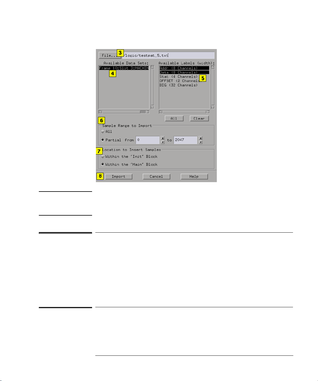
1. Select the Sequence tab.
2. Select File from the menu bar, then Import System Data File.
3. From the Import System Data File dialog, load the desired File Out tool
file. See the note below.
4. Select the desired data set (see page 59).
5. Select the desired labels (see page 59).
6. Select a data set range (see page 60) to import. If you select "Partial", the
range integers you specify will correspond to state numbers found in a
state listing of the same data set.
7. Select the location to insert the samples. Samples are inserted at the
beginning of the selected sequence. See the caution below.
8. Select Import.
58
Page 59
Chapter 1: Using the Agilent Technologies 16720A Pattern Generator
Importing System Data Files
NOTE: If in step 3 you entered the file name into the text entry field using a keyboard,
you must press the Return key on your keyboard to start the file import
process instead of selecting the Import field.
Data Sets
A data set is defined as data captured from a single source. For
example, the data captured from analyzer one of a logic analyzer is a
single source. Because the File Out tool allows multiple analyzers
worth of data to be stored within the same file, you pick only one data
set to import into the pattern generator.
Data Set Labels
All labels in a single data set are listed along with each label’s
corresponding channel width. If a label is wider than the pattern
59
Page 60

Chapter 1: Using the Agilent Technologies 16720A Pattern Generator
Importing System Data Files
generator’s maximum allowable channel width (32 channels), the label
is marked "unavailable". Labels wider than 32 channels cannot be
selected.
Data Set Range
When you select a data set, the "from" and "to" fields update to the
minimum and maximum values of the state listing. Both positive and
negative integers are valid.
CAUTION: If the range of data samples is too large for the pattern generator sequence
(1048576 vectors), a message will appear giving you the choice to continue or
not. If you continue, data will be imported starting from the beginning of the
file. At the point where you run out of vectors, data will be missing. To solve
this problem, reduce the range of samples you are importing.
60
Page 61

Chapter 1: Using the Agilent Technologies 16720A Pattern Generator
Loading and Saving Pattern Generator Configurations
Loading and Saving Pattern Generator
Configurations
You can save pattern generator settings and data to a configuration file.
You can also save any tools connected to the pattern generator. Later,
you can restore your data and settings by loading the configuration file.
• Loading Configuration Files (see the Agilent Technologies 16700A/B-
Series Logic Analysis System help volume)
• Saving Configuration Files (see the Agilent Technologies 16700A/B-
Series Logic Analysis System help volume)
61
Page 62
Chapter 1: Using the Agilent Technologies 16720A Pattern Generator
Selecting the Correct Probe Pod
Selecting the Correct Probe Pod
The following equivalent circuit information is provided to help you
select the appropriate clock and data pods for your application.
“Data Pod Descriptions” on page 63
“Clock Pod Descriptions” on page 67
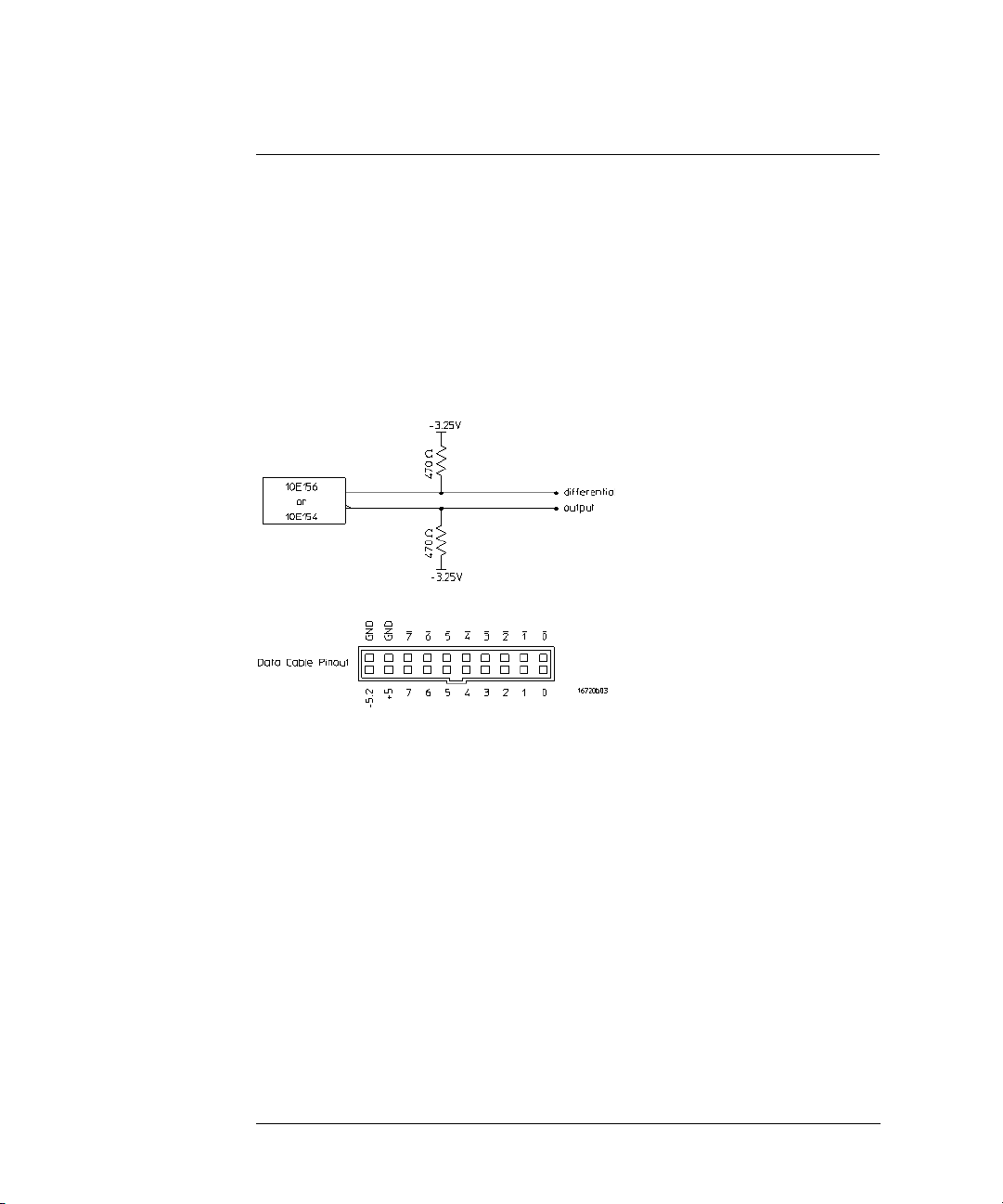
Data Cable Characteristics without a Data Pod
The data cables without a data pod provide an ECL-terminated (470
ohm; to -3.25V) differential signal. These signals are usable when
received by a differential receiver, preferably with a 100 ohm
termination across the lines. These signals should not be used singleended due to the slow fall time and shifted voltage threshold; they are
not ECL compatible.
62
Page 63
Chapter 1: Using the Agilent Technologies 16720A Pattern Generator
Selecting the Correct Probe Pod
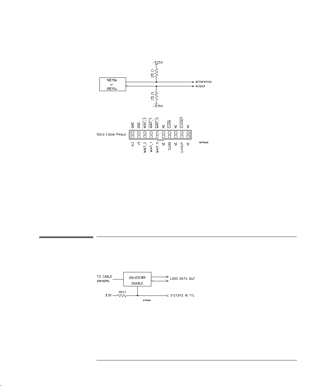
Clock Cable Characteristics without a Clock Pod
The clock out signals (CLKOUT and not-CLKOUT) without a clock pod
provide an ECL-terminated (215 ohm to -3.25V) differential signal.
These signals are usable when received by a differential receiver,
preferably with a 100 ohm termination across the lines. These signals
should not be used single-ended due to the slow fall time and shifted
voltage threshold; they are not ECL compatible.
See Also “Connecting the Probe Pods” on page 71
Data Pod Descriptions
E8141A LVDS Data Pod
Output type 65LVDS389 (LVDS data lines)
10H125 (TTL non-3-state channel 7)
3-state enable positive true TTL; no connect=enabled
Maximum clock 300 MHz
Skew Typical less than 1 ns, worst case 2 ns
Recommended lead set E8142A
63
Page 64

Chapter 1: Using the Agilent Technologies 16720A Pattern Generator
Selecting the Correct Probe Pod
10473A 3-State 2.5 V Data Pod
Output type 74AVC16244
3-state enable negative true, no connect=enabled
Maximum clock 300 MHz
Skew Typical less than 1 ns, worst case 2 ns
Recommended lead set 10498A
10476A 3-State 1.8 V Data Pod
Output type 74AVC16244
3-state enable negative true, no connect=enabled
Maximum clock 300 MHz
Skew Typical less than 1.5 ns, worst case 2.5 ns
Recommended lead set 10498A
10483 3-State 3.3V Data Pod
Output type 74AVC16244
3-state enable negative true, no connect=enabled
Maximum clock 300 MHz
Skew Typical less than 1 ns, worst case 2 ns
Recommended lead set 10498A
64
Page 65

Chapter 1: Using the Agilent Technologies 16720A Pattern Generator
Selecting the Correct Probe Pod
10469A PECL Data Pod
Output type 100EL09 (5V) with 348 pulldown to ground and
42 ohm in series
Maximum clock 300 MHz
Skew Typical less than 500 ps, worst case 1 ns
Recommended lead set 10498A
10471A LVPECL Data Pod
Output type 100LVEL90 (3.3V) with 215 ohm pulldown to
ground and 42 ohm in series
Maximum clock 300 MHz
Skew Typical less than 500 ps, worst case 1 ns.
Recommended lead set 10498A
10461A TTL Data Pod
Output type 10H125 with 100 ohm in series
Maximum clock 200 MHz
Skew Typical less than 2 ns; worst case 4 ns (note 1)
Recommended lead set 10498A
10462A 3-State TTL/CMOS Data Pod
Output type 74ACT11244 with 100 ohm in series
10H125 on non 3-state channel 7 (note 2),
3-state enable negative true, 100K ohm to GND, enabled
on no connect.
Maximum clock 100 MHz
Skew Typical less than 4 ns; worst case 12 ns (note 1)
Recommended lead set 10498A
65
Page 66

Chapter 1: Using the Agilent Technologies 16720A Pattern Generator
Selecting the Correct Probe Pod
10464A ECL Data Pod (terminated)
Output type 10H115 with 348 ohm pulldown, 42 ohm in series
Maximum clock 300 MHz
Skew Typical less than 1 ns; worst case 2 ns (note 1)
Recommended lead set 10498A
10465A ECL Data Pod (unterminated)
Output type 10H115 (no termination)
Maximum clock 300 MHz
Skew Typical less than 1 ns; worst case 2 ns (note 1)
Recommended lead set 10347A
10466A 3-State TTL/3.3 volt Data Pod
Output type 74LVT244 with 100 ohm in series
10H125 on non 3-state channel 7 (see note 2)
3-state enable negative true, 100K ohm to GND, enabled on no
connect.
Maximum clock 200 MHz
Skew Typical less than 3 ns; worst case 7 ns (note 1)
Recommended lead set 10498A
Note 1
Typical skew measurements made at the pod connector with approximately
10 pF/50K ohm load to GND; worst case skew numbers are a calculation of
worst case conditions through circuits. Both numbers apply to any channel
within a single or multiple module system.
Note 2
Channel 7 on the 3-state pods has been brought out in parallel as a
non 3-state signal. By looping this output back into the 3-state enable
line, the channel can be used as a 3-state enable.
See Also “Clock Pod Descriptions” on page 67
66
Page 67

Chapter 1: Using the Agilent Technologies 16720A Pattern Generator
Selecting the Correct Probe Pod
“Connecting the Probe Pods” on page 71
Clock Pod Descriptions
E8140A LVDS Clock Pod
Clock output type 65LVDS179 (LVDS) and 10H125 (TTL)
Clock output rate 200 MHz maximum (LVDS and TTL)
Clock out delay approximately 8 ns total in 14 steps
Clock input type 65LVDS179 (LVDS with 100 ohm)
Clock input rate DC to 150 MHz (LVDS)
Pattern input rate 10H124 (TTL) (no connect=logic 1)
Clock in to clock out approximately 30 ns
Patt in to recognition approximately 15 ns + 1 clock period
Recommended lead set 10498A
10472A 2.5 V Clock Pod
Clock output type 74AVC16244
Clock output rate 200 MHz maximum
Clock out delay approximately 8 ns total in 14 steps
Clock input type 74AVC16244 (3.6 V maximum)
Clock input rate DC to 200 MHz
Pattern input rate 74AVC16244 (3.6 V maximum; no connect=logic 0)
Clock in to clock out approximately 30 ns
Patt in to recognition approximately 15 ns + 1 clock period
Recommended lead set 10498A
67
Page 68

Chapter 1: Using the Agilent Technologies 16720A Pattern Generator
Selecting the Correct Probe Pod
10475A 1.8 V Clock Pod
Clock output type 74AVC16244
Clock output rate 200 MHz maximum
Clock out delay approximately 8 ns total in 14 steps
Clock input type 74AVC16244 (3.6 V maximum)
Clock input rate DC to 200 MHz
Pattern input rate 74AVC16244 (3.6 V maximum; no connect=logic 0)
Clock in to clock out approximately 30 ns
Patt in to recognition approximately 15 ns + 1 clock period
Recommended lead set 10498A
10477A 3.3 V Clock Pod
Clock output type 74AVC16244
Clock output rate 200 MHz maximum
Clock out delay approximately 8 ns total in 14 steps
Clock input type 74AVC16244 (3.6 V maximum)
Clock input rate DC to 200 MHz
Pattern input rate 74AVC16244 (3.6 V maximum; no connect=logic 0)
Clock in to clock out approximately 30 ns
Patt in to recognition approximately 15 ns + 1 clock period
Recommended lead set 10498A
68
Page 69

Chapter 1: Using the Agilent Technologies 16720A Pattern Generator
Selecting the Correct Probe Pod
10468A PECL Clock Pod
Clock output type 100EL90 (5V0 with 348 ohm pulldown to ground
and 42 ohm in series
Clock output rate 300 MHz maximum
Clock input delay approximately 8 ns total in 14 steps
Clock input type 100EL91 PECL (5V), no termination (no connect
is logic 0)
Clock input rate DC to 300 MHz
Pattern input type 100EL91 PECL (5V), no termination (no connect
is logic 0)
Recommended lead set 10498A
10470A LVPECL Clock Pod
Clock output type 100LVEL90 (3.3V) with 215 ohm pulldown to
ground and 42 ohm in series
Clock output rate 300 MHz maximum
Clock out delay approximately 8 ns in 14 steps
Clock input type 100LVEL91 PECL (3.3V), no termination
Clock input rate DC to 300 MHz
Pattern input type 100LVEL91 PECL (3.3V), no termination
Clock in to clock out approximately 30 ns
Patt in to recognition approximately 15 ns + up to 1 clock period
Recommended lead set 10498A
69
Page 70

Chapter 1: Using the Agilent Technologies 16720A Pattern Generator
Selecting the Correct Probe Pod
10460A TTL Clock Pod
Clock output type 10H125 with 42 ohm series; true & inverted
Clock output rate 100 MHz maximum
Clock out delay 8 ns maximum in 14 steps
Clock input type TTL - 10H124
Clock input rate DC to 100 MHz
Pattern input type TTL - 10H124 (no connect is logic 1)
Clk-in to clk-out Approx. 30 ns
Patt-in to recognition Approx. 15 ns + up to 1 clk period
Recommended lead set 10498A
10463A ECL Clock Pod
Clock output type 10H116 differential unterminated; differential
with 348 ohm to -5.2v and 42 ohm series
Clock output rate 300 MHz maximum
Clock out delay 11 ns maximum in 9 steps
Clock input type ECL - 10H116 with 50K ohm to -5.2v
Clock input rate DC to 300 MHz
Pattern input type ECL - 10H116 with 50K ohm (no connect is logic 0)
Clk-in to clk-out Approx. 30 ns
Patt-in to recognition Approx. 15 ns + up to 1 clk period
Recommended lead set 10498A
See Also “Data Pod Descriptions” on page 63
“Connecting the Probe Pods” on page 71
70
Page 71
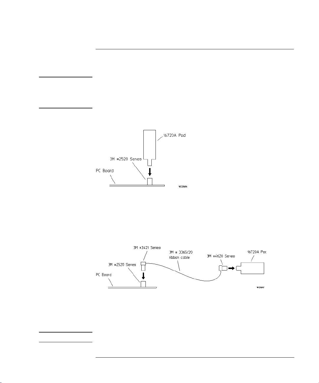
Chapter 1: Using the Agilent Technologies 16720A Pattern Generator
Connecting the Probe Pods
Connecting the Probe Pods
NOTE: Clock and Data pods are required for a proper signal interface. There are
different types (see page 62) available, and they should match your target
circuit characteristics. In addition, depending on the Vector Output Mode (see
page 12) selected, some pods may not be available for use.
Direct Pod-to-Board Connection
Plug the pod directly into the ©3M 2520-series, or similar alternative
connector on the PC board.
Jumper Cable-to-Pod Connection
Use this method when you have clearance problems on the PC board.
Construct a flat-ribbon cable and connect as shown above.
NOTE: You can obtain equivalent connectors from sources other than 3M.
71
Page 72

Chapter 1: Using the Agilent Technologies 16720A Pattern Generator
Connecting the Probe Pods
Probe Lead Set to Board Pin Connection
Two probe lead assemblies are available for connecting to PC board
pins.
• 10498A 8-channel probe lead set.
• 10347A 8-channel probe lead set, 50-ohm coaxial for unterminated signals.
The probe tips of both lead sets plug directly into any 0.1-inch grid with
0.026- to 0.033-inch diameter round pins or 0.025-inch square pins.
These probe tips work with the 5090-4356 surface mount grabbers and
the 5959-0288 through-hole grabbers.
NOTE: The LVDS Data Pod must be connected to the leads in such a way that the
striped row of cables faces up.
72
Page 73

Chapter 1: Using the Agilent Technologies 16720A Pattern Generator
Editing Sequences
Editing Sequences
•“Cutting, Copying, Pasting, and Deleting Sequence Lines” on page 73
•“Deleting Sequence Lines” on page 74
•“Inserting Blank Sequence Lines” on page 75
•“Go to a Line Number” on page 76
•“Positioning the Sequence” on page 76
•“Using Ditto " values” on page 77
Cutting, Copying, Pasting, and Deleting Sequence Lines
NOTE: When you use the Cut and Copy operations from the menu bar, you are
placing the sequence lines in a temporary storage buffer. All subsequent Paste
operations will insert sequence lines from the storage buffer until new lines
are cut or copied. When you use the Delete operation from the menu bar, the
sequence lines are not placed in the temporary buffer. They are just deleted.
1. Select the sequence lines to cut, copy, or delete by highlighting the first
line.
2. To select the entire sequence, select Edit from the menu bar, then Select
All Lines.
3. From the menu bar, select Edit, then Cut Line(s), Copy Line(s), or
Delete Lines(s).
4. Select the sequence line just above where you want to paste the sequence
lines. This positions the cursor. When pasting sequence lines, the lines are
placed after the cursor line.
5. If you are pasting cut or copied lines, select Edit from the menu bar, then
Paste Line(s).
73
Page 74

Chapter 1: Using the Agilent Technologies 16720A Pattern Generator
Editing Sequences
NOTE: Cutting or deleting all the sequence lines causes the sequence to be reset to
the power-up state.
Restrictions on Use
The above operations will not be allowed if the result of the operation
places an instruction on one of the following vectors:
• The first or second vector of the INIT sequence.
• The first or second vector of the MAIN sequence.
• The last vector of the MAIN sequence.
In addition, the above operations will not be allowed if the result of the
operation places a hardware instruction immediately after another
instruction. Hardware instructions must follow data vectors.
Deleting Sequence Lines
CAUTION: When you delete sequence lines, they are permanently removed. If you want
to place them in a temporary storage buffer, use the Cut (see page 73)
operation from the menu bar.
NOTE: To highlight a line, drag from the bottom of the desired line to the top of the
desired line.
Deleting Single Lines
• To delete single lines, highlight the line that is to be deleted.
• Select Delete Line(s) from the Edit menu.
Deleting Multiple Lines
• To delete multiple lines, highlight the lines that are to be deleted.
• Select Delete Line(s) from the Edit menu.
74
Page 75

Chapter 1: Using the Agilent Technologies 16720A Pattern Generator
Editing Sequences
Delete All Lines
To delete all lines in a sequence, go to the menu bar and select Edit ->
Select All Lines, then Edit -> Delete Lines(s). Deleting all lines causes
the sequence to be reset to the power-up state.
Restrictions on Use
You are not allowed to delete the following sequence lines:
• The INIT START line.
• The INIT END line.
• The MAIN START line.
• The MAIN END line.
• The MACRO START line.
• The MACRO END line.
A delete will not be performed if the result of the delete places an
instruction on one of the following lines:
• The first or second vector of the INIT sequence.
• The first or second vector of the MAIN sequence.
• The last vector of the MAIN sequence.
A delete will not be performed if the result of the delete does either of
the following:
• Places a hardware instruction immediately after another instruction.
• Causes the MAIN sequence to contain fewer than two data vectors.
Inserting Blank Sequence Lines
Inserting blank lines (see page 77) is a very useful operation when
starting a new sequence. After you insert a new line, you replace the
ditto values with the desired normal data values.
75
Page 76

Chapter 1: Using the Agilent Technologies 16720A Pattern Generator
Editing Sequences
Inserting Blank Lines
1. To position the cursor, select the vector line directly above where you want
to insert lines.
2. Select Insert After, then select Vector to insert a new vector line.
3. Repeat for each new vector line you want to insert.
NOTE: You can also insert blank sequence lines by using the keyboard as follows: *
Select the vector line directly above where you want to insert the new data
vector. * Press the Insert key on your keyboard one time for each new vector
line you want to insert.
NOTE: The new blank lines are inserted with ditto values.
See Also
“Using Ditto " values” on page 77
Go to a Line Number
1. From within the Sequence or Macro tab, select any vector line.
2. Select Goto Line.
3. In the Goto Line dialog that appears, enter the desired line number.
4. Select OK.
See Also
“Positioning the Sequence” on page 76
Positioning the Sequence
Using the Keyboard
Among the keyboard keys that insert and delete data vectors, the
pattern generator defines four other keys used to position the
76
Page 77

Chapter 1: Using the Agilent Technologies 16720A Pattern Generator
Editing Sequences
sequence when either the Sequence or Macro tab is active.
Specifically, these additional keys are defined:
1. Home - move to the first line of the sequence.
2. End - move to the last line of the sequence.
3. Page Up - scroll upward by one screen worth of data.
4. Page Down - scroll downward by one screen worth of data.
To use the positioning keys, perform the following steps:
1. From within Sequence or Macro, select any vector line.
2. Press one of the above keys on the keyboard.
See Also
“Go to a Line Number” on page 76
Using Ditto " values
In any existing data vector, with the exception of the first, you can
replace normal data values with ditto values (designated by the double
quotation marks).
Ditto values indicate that the previous data value should be repeated
for the current data vector. Ditto values save you effort by requiring
you to only enter in the data values that change.
NOTE: When you insert blank lines, they are inserted as ditto values.
1. From either the Sequence or Macro tab, select the data field that you
want to edit. This positions the cursor.
2. Select Insert After.
3. Select Vector.
See Also
“Inserting Blank Sequence Lines” on page 75
77
Page 78

Chapter 1: Using the Agilent Technologies 16720A Pattern Generator
Working with Instruction Types
Working with Instruction Types
Instructions are like programming commands. They are inserted into a
sequence for the purpose of executing their designated control over
the flow of the sequence. There are two types of instructions: hardware
and software. The differences between these types are described
below.
Inserting Instructions into Sequences
1. Select the vector line directly above where you want to insert the new
instruction.
2. Select Insert After.
3. Select the desired instruction to insert.
Hardware Instruction Types
The following hardware instruction types are available. Each of these
instructions can affect external hardware or the pattern generator
hardware.
•“The Break Instruction” on page 79
•“The Signal IMB Instruction” on page 79
•“The Wait IMB Event Instruction” on page 80
•“The Wait External Event Instruction” on page 80
Software Instruction Types
The following software instruction types are available. Each of these
instructions only affects the execution flow of the currently running
sequence. However, a User Macro software instruction can include
hardware instructions.
•“The User Macro Instruction” on page 81
78
Page 79

Chapter 1: Using the Agilent Technologies 16720A Pattern Generator
•“The Repeat Loop Instruction” on page 82
See Also “Building a Main Sequence” on page 23
“Building an Initialization Sequence” on page 21
“Building a User Macro” on page 25
The Break Instruction
The Break instruction causes a break at the current vector. In single
run mode, this instruction halts the sequence and holds the outputs at
the value of the previously outputted data value. In repetitive run
mode, this instruction pauses the sequence at the current vector
momentarily, then continues. The duration of the pause depends on
the activity of other modules in the frame.
Working with Instruction Types
Restrictions on Use
The Break instruction must follow data vectors. Also, the Break
instruction is not allowed on the following vector lines of a sequence:
• The first or second vector of the INIT sequence.
• The first or second vector of the MAIN sequence.
• The last vector of the MAIN sequence.
The Signal IMB Instruction
The Signal IMB instruction creates an arming signal on the
intermodule bus when the instruction is executed. This arming
signal allows the pattern generator to cross trigger other modules in
the frame.
Restrictions on Use
The Signal IMB instruction, as with all hardware instructions, must
follow data vectors. Also, the Signal IMB instruction can only be used
79
Page 80

Chapter 1: Using the Agilent Technologies 16720A Pattern Generator
Working with Instruction Types
one time in a sequence, and consequently it is not allowed in a user
macro or a repeat loop. The Signal IMB instruction is not allowed on
the following vector lines of a sequence:
• The first or second vector of the INIT sequence.
• The first or second vector of the MAIN sequence.
• The last vector of the MAIN sequence.
See Also Using the Intermodule Window (see the Agilent Technologies 16700A/B-
Series Logic Analysis System help volume)
The Wait IMB Event Instruction
The Wait IMB Event instruction halts the execution of the program
sequence until an IMB signal is received by the pattern generator.
Restrictions on Use
The Wait IMB Event instruction, as with all hardware instructions,
must follow data vectors. Also, the Wait IMB Event instruction can only
be used one time in a sequence, and consequently it is not allowed in a
user macro or a repeat loop. The Wait IMB Event instruction is not
allowed on the following vector lines of a sequence:
• The first or second vector of the INIT sequence.
• The first or second vector of the MAIN sequence.
• The last vector of the MAIN sequence.
The Wait External Event Instruction
The Wait External Event instruction halts the execution of the program
sequence until one of four designated events (A-D) is received by the
pattern generator.
Because the Wait External Event is an OR’ing function of the toggled
80
Page 81

Chapter 1: Using the Agilent Technologies 16720A Pattern Generator
Working with Instruction Types
"On" wait patterns, as soon as one of the selected wait patterns is
satisfied, the sequence continues. The wait patterns are specified on
the three input lines of the clock pod: Wait0, Wait1, and Wait2.
To choose and configure a particular event, select the Wait External
Event instruction, then from the External Wait Pattern dialog, toggle
the appropriate fields.
Restrictions on Use
The Wait External Event instruction, as with all hardware instructions,
must follow data vectors. Wait External Events are not allowed on the
following vector lines of a sequence:
• The first or second vector of the INIT sequence.
• The first or second vector of the MAIN sequence.
• The last vector of the MAIN sequence.
The User Macro Instruction
The User Macro instruction lets you insert a group of vectors that have
81
Page 82

Chapter 1: Using the Agilent Technologies 16720A Pattern Generator
Working with Instruction Types
a specific function. At run time, the user macro is expanded into its
corresponding vectors. A typical macro application would be a generic
test stimulus that is used by multiple circuits. By containing the device
or circuit specific test vectors within a macro, you can simply
interchange the macro and reuse the same INIT and MAIN
SEQUENCE.
Macros can contain parameters. Using parameters in a macro gives you
the same benefit as using macros in a sequence. By passing
parameters, you can reuse the same macro for other purposes.
Restrictions on Use
The User Macro instruction is not allowed on the following vector lines
of a sequence:
• The first or second vector of the INIT sequence.
• The first or second vector of the MAIN sequence.
• The last vector of the MAIN sequence.
See Also “Building a User Macro” on page 25
“Working with Macro Parameters” on page 98
The Repeat Loop Instruction
The Repeat Loop instruction inserts the start and end vectors of a
repeat loop, along with one blank data vector row, below the selected
vector row. Once the loop has been created, you can insert or copy
vectors and instructions into the loop.
82
Page 83
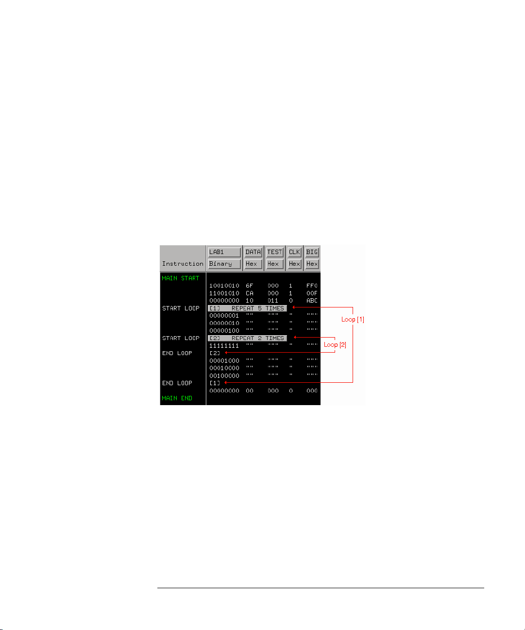
Chapter 1: Using the Agilent Technologies 16720A Pattern Generator
Working with Instruction Types
Set the number of loop repetitions (maximum 20,000) by selecting the
"Start Loop" vector line and editing the Loop Count dialog. At run
time, the loop count determines the number of times to expand the
loop’s body into individual vectors. Both the start and end vectors of a
repeat loop are removed from the sequence if either one is included in
a delete operation.
Nested Repeat Loop Instructions
This example shows a nested loop. Loop[1] is a walking ones pattern
that is repeated five times. Loop[2] is a bit pattern of all ones that is
repeated twice directly in the middle of the walking ones pattern of
Loop[1].
Restrictions on Use
The following instructions can NOT be used in a repeat loop:
• The Signal IMB instruction.
• The Wait IMB Event instruction.
The Repeat Loop instruction is not allowed on the following vector
lines of a sequence:
• The first or second vector of the INIT sequence.
• The first or second vector of the MAIN sequence.
83
Page 84

Chapter 1: Using the Agilent Technologies 16720A Pattern Generator
Working with Instruction Types
• The last vector of the MAIN sequence.
84
Page 85

Chapter 1: Using the Agilent Technologies 16720A Pattern Generator
Working with Labels and Pods
Working with Labels and Pods
Access label and pod operations from either the Edit pick in the menu
bar, or under the label name field itself. When you select operations
from the menu bar, they are global to all labels or pods in the window.
When you select operations from under the label name, they are
directed at the individual label.
In addition, label and pod operations in the Sequence and Macro
displays are centered around adding or deleting. Operations in the
Format display are centered around initial creation and configuration.
NOTE: Label operations are performed on labels assigned in Format. If labels are not
created, assigned bits, and turned on in Format, they do not appear in
Sequence or Macro. Also, depending on the Vector Output Mode (see
page 12), some pods may not be available.
Operations in Format
•“Creating and Inserting New Labels” on page 86
•“Deleting Labels” on page 87
•“Renaming Existing Labels” on page 88
•“Reordering a Label's Pod Bits” on page 89
•“Turning Labels On/Off” on page 89
•“Clearing Format Labels” on page 90
•“Finding a label” on page 92
•“Swap Pods” on page 90
•“Clear Pods” on page 91
•“Assigning Bits to a Label” on page 91
•“Label Polarity” on page 92
Operations in Sequence and Macro
•“Inserting Pre-assigned Labels” on page 88
85
Page 86

Chapter 1: Using the Agilent Technologies 16720A Pattern Generator
Working with Labels and Pods
•“Deleting Labels” on page 87
•“Replace Labels” on page 93
•“Finding a label” on page 92
•“Appending Labels” on page 94
•“Insert All Labels” on page 95
•“Delete All Labels” on page 95
•“Searching for Labels” on page 90
•“Setting Column Color” on page 96
•“Adjusting Column Width” on page 96
•“Rearranging the Label Order” on page 97
•“Setting the Numeric Base” on page 97
•“Setting the Label Font Size” on page 95
Creating and Inserting New Labels
Creating New Labels in Format
You create labels in Format to uniquely identify groups of assigned pod
bits (see page 91) that have a common purpose or identity. Inserting
and assigning labels are part of the mapping process (see page 11) for
your application.
1. Select the label where you want to insert the new label, then select Insert
before or Insert after.
2. In the Enter Label Name dialog that appears, enter in the new label name.
If you do not provide a label name, a default name is assigned.
3. Select OK if you are done, or Apply if you have more labels to insert.
86
Page 87

Chapter 1: Using the Agilent Technologies 16720A Pattern Generator
NOTE: Duplicate label names are not allowed.
Mode
If you are creating a series of new labels, you have the option to
automatically assign bits in a "walking ones" pattern across the label
series. You do this by toggling the Mode field to Walking ones.
Select the Pod, the starting Bit, and the walk direction. As you enter
new label names and select Apply, a single bit is automatically assigned
under each new label in a "walking ones" pattern.
Working with Labels and Pods
Deleting Labels
1. Select the label to be deleted.
2. Select Delete.
See Also “Clearing Format Labels” on page 90
“Delete All Labels” on page 95
87
Page 88

Chapter 1: Using the Agilent Technologies 16720A Pattern Generator
Working with Labels and Pods
Inserting Pre-assigned Labels
NOTE: If labels are not created, assigned bits, and turned on in Format, they do not
appear in subsequent label operation dialogs in Sequence and Macro.
1. From the Sequence or Macro tab, select the label where you want to insert
the new label, then select Insert Before or Insert After.
2. In the Select Label dialog that appears, select the pre-assigned label name
to insert.
3. Select OK if you are done, or Apply if you have more labels to insert.
See Also “Searching for Labels” on page 90
Renaming Existing Labels
1. Under Format, select the label you want to rename, then select Rename.
2. In the Rename dialog, enter in the new label name.
3. Select OK if you are done, or Apply if you have more labels to rename.
NOTE: When you select Apply, the next label is automatically highlighted. This lets
you rename multiple labels very quickly.
88
Page 89

Chapter 1: Using the Agilent Technologies 16720A Pattern Generator
Working with Labels and Pods
Reordering a Label’s Pod Bits
Use the Reorder bits feature to remap the physical probe connections
to the interface without changing the actual probe connections. This
feature allows the probe tips for each channel to be physically
connected where convenient.
1. Under the Format tab, select the label you want to reorder bits on, then
select Reorder bits.
2. Set the bit order by one of the following options:
• To reorder bits individually, for each channel, enter the number of the
bits you want to map the channel to.
• To arrange the bits sequentially, select the field at the top of the dialog,
then select Default Order.
• To reverse the order of the bytes, select the field at the top of the
dialog, then select Big Endian - Little Endian mapping. This option is
only available for labels that have either 24 or 48 channels.
3. Select OK.
NOTE: Reordering the bits of a label does not reorder the physical output signals of
the channels assigned to that label. The bit order of a label is a displayorientation concept, useful only when entering data values.
Turning Labels On/Off
Turning labels off prevents output signals from appearing on the
associated probe channels. When a label is turned off, it is removed
from the Sequence and Macro areas. However, the label’s name and bit
assignments are preserved.
To toggle labels On/Off in Format, select the label that you want to
modify and toggle the Label On/Off selection.
89
Page 90
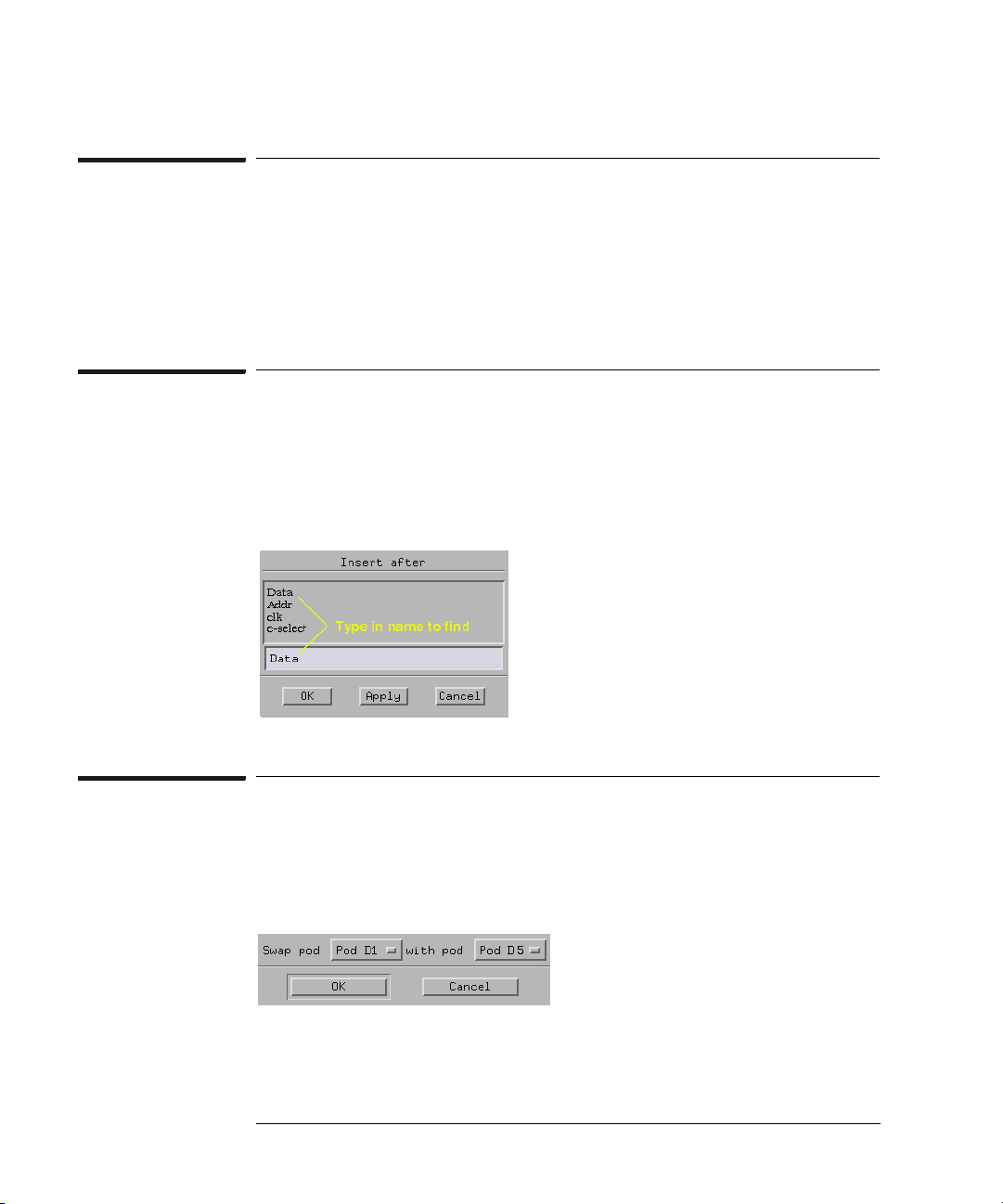
Chapter 1: Using the Agilent Technologies 16720A Pattern Generator
Working with Labels and Pods
Clearing Format Labels
The Clear Format Labels command is located under Edit in the
Format menu bar. When you select Clear Format Labels, all userassigned labels are permanently removed, and the default label Lab1 is
reset.
Searching for Labels
In all label selection dialogs, where a list of label names appears, a text
entry field is available for a quick search of label names. Simply enter in
a search string, and all labels that begin with that string appear in the
list.
Swap Pods
The Swap Pods command is located under Edit in the Format menu
bar. When you select Swap Pods, the bit assignments for the two
designated pods are swapped across all labels.
90
Page 91
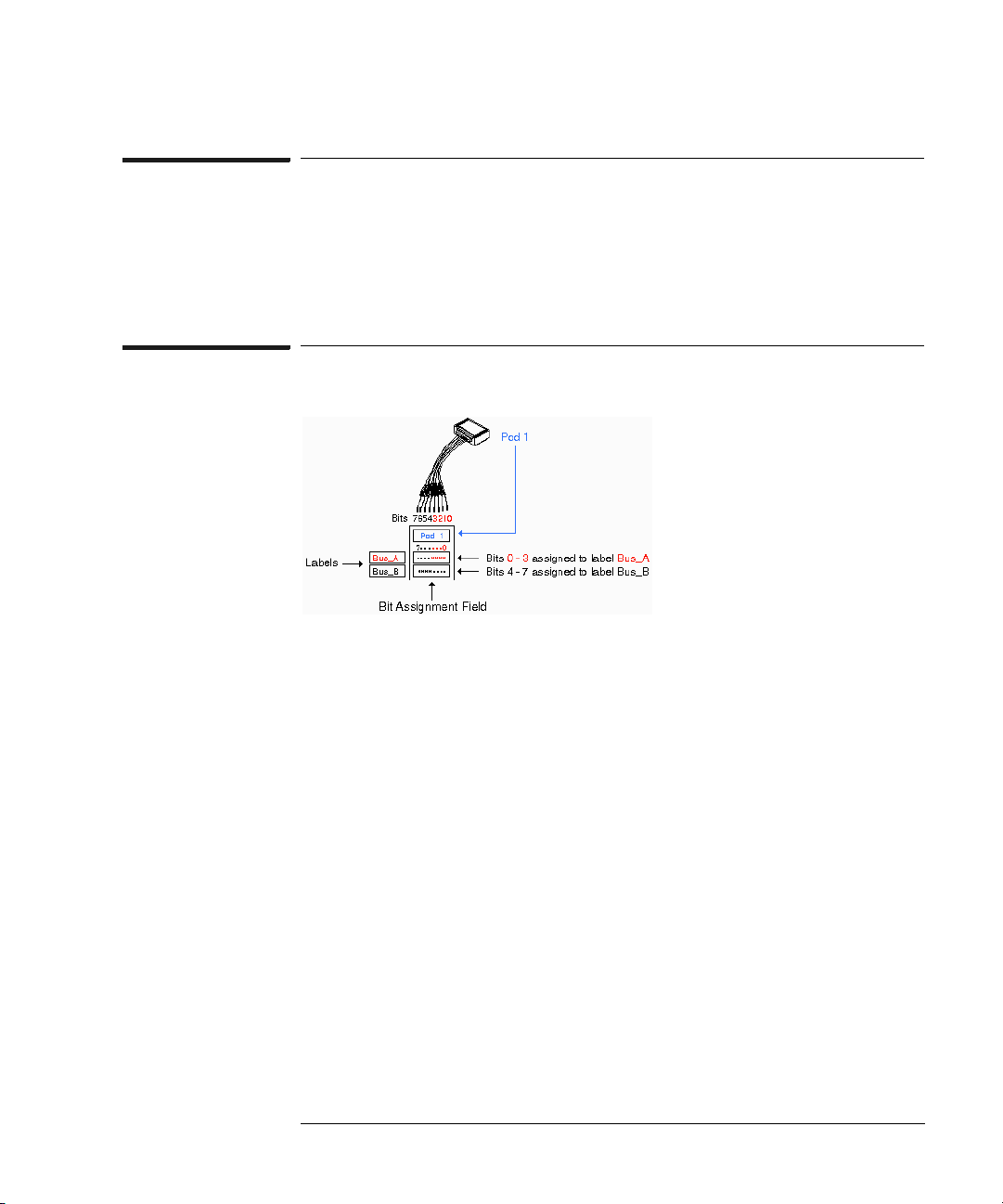
Chapter 1: Using the Agilent Technologies 16720A Pattern Generator
Working with Labels and Pods
Clear Pods
The Clear Pods command is located under Edit in the Format menu
bar. When you select Clear Pods, all bit assignments for all labels
under the designated pod are cleared.
Assigning Bits to a Label
The bits in a label correspond to the physical pattern generator probe
channels. When you run the pattern generator, data is output on all bits
(channels) that are assigned to labels. Unassigned bits are inactive.
• An asterisk "*" indicates an assigned bit.
• A period "." indicates an unassigned bit.
To Assign Bits
1. Select the bit assignment field to the right of the label name you want to
define. Each bit assignment field corresponds to the data pod listed above
it.
2. Select the bits you want to change, toggling them between an asterisk and
a period.
3. When the bits are assigned as desired, close the dialog box.
Select the bit assignment field or dialog to see a shortcut menu for
assigning groups of bits.
91
Page 92

Chapter 1: Using the Agilent Technologies 16720A Pattern Generator
Working with Labels and Pods
NOTE: Labels can have a maximum of 32 channels assigned to them, however, you
cannot assign any single output channel to more than one label.
Bits assigned to a label are numbered from right to left. The least
significant assigned bit on the far right is numbered 0. The next
assigned bit to the left is numbered 1, and so on. Labels can contain
bits that are not consecutive; however, bits are always numbered
consecutively within a label.
Label Polarity
The pattern generator can display each label’s data in both positive and
negative logic. The default polarity for all labels is positive. To toggle
the polarity, select the label’s polarity field under the Format tab.
NOTE: Toggling the polarity of a label does not toggle the physical output signal. The
polarity of a label is a display orientation concept, useful only when entering
data values.
Finding a label
Access the Find Label feature under Edit in the menu bar of all tabs.
The Find Label feature locates specified labels, then displays them.
The search functionality is similar to a text based keyword search.
After you enter the label name and select Next or Prev, the list of labels
is rolled, exposing the label whose text characters, left to right, match
the label name entered.
You can search for a complete label name as shown below in example 1,
or enter just the base name and use the Next or Prev fields to roll
through the list as in example 2.
Example 1
You have a list of labels named Data1 through Data15. Enter the
complete name Data7 in the text entry field, then select Next. The
92
Page 93
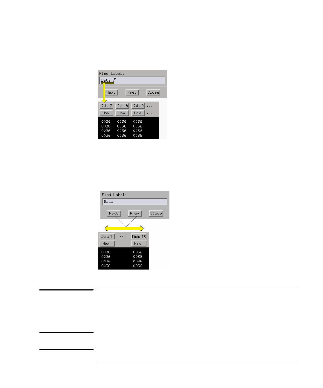
Chapter 1: Using the Agilent Technologies 16720A Pattern Generator
Working with Labels and Pods
label named Data7 appears on the left-most side of the displayed
labels.
Example 2
You have a list of labels named Data1 through Data15. Enter only the
base name Data in the text entry field, then use the Next or Prev fields
to roll the list of labels.
Replace Labels
The Replace Label command is available in the Sequence and Macro
tabs.
NOTE: To highlight a line, drag from the bottom of the desired line to the top of the
desired line.
93
Page 94

Chapter 1: Using the Agilent Technologies 16720A Pattern Generator
Working with Labels and Pods
1. Highlight the label to replace.
2. Select Replace.
3. From the Select Label dialog that appears, select one or more new labels to
replace the existing label.
4. Select OK if you are done, or Apply if you have more labels to replace.
See Also “Searching for Labels” on page 90
Appending Labels
The Append Label command is located under Edit in the Sequence
and Macro menu bar. The Append Label command adds labels to the
right of the list of labels in Sequence and Macro.
1. In Sequence or Macro, select Edit, then select Append Label.
2. From the Select Label dialog that appears, select the new labels to append.
3. Select OK if you are done, or Apply if you have more labels to append.
See Also “Searching for Labels” on page 90
94
Page 95

Chapter 1: Using the Agilent Technologies 16720A Pattern Generator
Working with Labels and Pods
Insert All Labels
The Insert All Labels command is located under Edit in the Sequence
and Macro menu bar. Select this command to insert all valid labels
under the Format tab into the sequence.
Delete All Labels
The Delete All Labels command is located under Edit in the Sequence
and Macro menu bar. Select this command to delete all assigned labels
in the sequence.
Setting the Label Font Size
Font settings are global. The font size you select is applied to all text in
the display area.
1. From the menu bar select Options, then select Font.
2. Select a font size from the list.
Example of Font Sizes
95
Page 96

Chapter 1: Using the Agilent Technologies 16720A Pattern Generator
Working with Labels and Pods
Adjusting Column Width
1. Select the right edge of the label box.
2. Drag the box edge to the desired width.
Setting Column Color
NOTE: To highlight a line, drag from the bottom of the desired line to the top of the
desired line.
1. Select the Sequence or Macro tab.
2. Highlight a label, then select Change Color.
3. Select the desired color.
4. Select OK.
Setting Default Label Color
The Default Label Color command lets you set the label color for all
new labels inserted into either Sequence or Macro.
1. Select the Sequence or Macro tab.
2. From the menu bar, select Options, then select Default Label Color.
3. From the Default Color dialog that appears, select the desired color.
4. Select OK.
96
Page 97
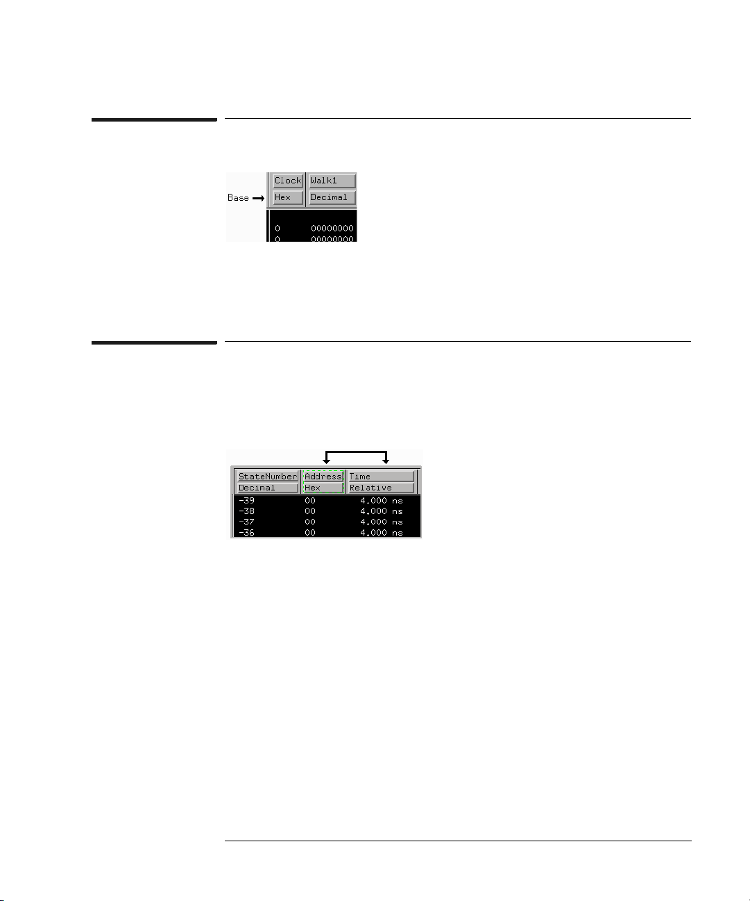
Chapter 1: Using the Agilent Technologies 16720A Pattern Generator
Setting the Numeric Base
1. Select the label’s base field.
2. Select the desired base type.
Rearranging the Label Order
1. Select the desired label.
2. Drag the label to its new location.
Working with Labels and Pods
97
Page 98

Chapter 1: Using the Agilent Technologies 16720A Pattern Generator
Working with Macro Parameters
Working with Macro Parameters
Parameters are used to pass values into macros. A major benefit in
passing parameters is that you keep a macro’s functionality generic and
still direct specific action identified by parameters. Think of a
parameter as the only part of a macro that changes as the macro is
reused.
Use this procedure after creating your macro or recalling it in the
Macro display:
1. From Macro, turn the desired parameters on. (see page 98)
2. Insert the parameters. (see page 99)
3. Assign values to the parameters. (see page 99)
NOTE: Macro parameters are passed as 32-bit values. If fewer than 32 bits are
assigned to a label in Format, the most significant bits of the parameter value
are truncated when the parameter is used as data for the given label.
See Also “Building a User Macro” on page 25
“Recalling Macros” on page 114
“Removing Parameters from a Macro” on page 100
Turning Parameters On
You have 10 available parameters per macro. You cannot use
parameters until you turn them on.
1. From Macro, select Parameters..., then select On.
2. Optional - If you want a custom parameter name, select anywhere in the
name field and enter a name.
3. Select Close.
98
Page 99

Chapter 1: Using the Agilent Technologies 16720A Pattern Generator
Inserting Parameters into a Macro
Working with Macro Parameters
NOTE: Because parameters replace a data field within data vectors, you can only set
them on an existing data vector. They cannot be set on instruction vectors.
The following procedure is performed after your macro is created,
recalled into the Macro display, and the parameter is turned on. (see
page 98)
1. From Macro, select the data field you want to replace. This positions the
cursor.
2. Select over any vector line and select Set Parameter.
3. From the Set Parameter dialog, select the parameter you want to set.
4. Select OK.
See Also “Working with Macro Parameters” on page 98
Assigning Parameter Values
Parameter values are easily set or changed from the tab in which the
99
Page 100

Chapter 1: Using the Agilent Technologies 16720A Pattern Generator
Working with Macro Parameters
macro instruction was inserted. Assigned parameter values are
displayed in parentheses next to their corresponding macro
instruction. Parameter values are always displayed as hexadecimal
values.
1. From the Sequence tab (or the Macro tab, if the macro is nested), select
the macro instruction.
2. From the Set Parameters dialog that appears, enter in the new parameter
values.
3. Select OK.
NOTE: Macro parameters are passed as 32-bit values. If fewer than 32 bits are
assigned to a label in Format, the most significant bits of the parameter value
are truncated when the parameter is used as data for the given label.
Removing Parameters from a Macro
1. From Macro, select the data field that contains the parameter to be
removed.
2. Highlight over any vector line and select Clear Parameter.
100
 Loading...