


Installation Guide
16700B
Measurement
Modules
16allp01
Publication Number 16700-97014
© Copyright Agilent Technologies 2000
All Rights Reserved
16702B
Logic Analysis Systems


Contents
System Overview Agilent 16700B
System Overview Agilent 16702B
Mouse and Keyboard
Monitor Connection
Proper Cooling
Monitor Configuration 16700B
Monitor Configuration 16702B 10
Changing Monitors
LAN
Printers
External Disk Drive 15
External Disk Drive & CD-ROM Drive
Software Installation
16701A/B Expander Frame
Probing
Self-Test
Specifications & Characteristics
Disaster Recovery
Saving System Settings
4
5
6
7
8
9
11
12
13
19
21
24
25
31
32
33
35
16allp02
Reloading System Settings
Multiframe
Proper Cleaning
General Installations
16517/18A
16522A
16533/34A
16557D
16710/11/12A
16715-19A /50-52A
16720A
36
37
40
42
43
50
54
64
69
72
77

16700B Overview
16700B Mainframe
Power Cable
Making Basic
Measurements
(If ordered)
Monitor
Monitor Cable
Monitor Power Cable
Training Board and Training Kit
Additional Connections
External Disk Drive and Cable
(Data Drive - Option 008)
(Boot Drive - Option 009)
16allp04
Keyboard
and
Mouse
16701A/B
Expander Frame
Printer
and
Cable
4

16702B Overview
16702B
Mainframe
Power Cable
Additional Connections
Making Basic
Measurements
Training Board and
Training Kit
Mouse and
Keyboard
16allp05
Monitor
Monitor Cable and
Monitor Power Cable
(If ordered)
External Disk Drive and Cable
(Data Drive - Option 008)
(Boot Drive - Option 009)
Printer and
Cable
16701A/B Expander Frame
5

Mouse & Keyboard
for 16700B/ 16702B
The 16700B must have the system mouse and keyboard connected for the system to boot
up properly.
Once enabled on the LAN, the system can be operated remotely without a keyboard or
mouse.
16700B
or
16702B
16allp06
Target
Target
Control
Control
To16701 Expansion FrameTo 16701 Expansion Frame
Keyboard Mouse
Keyboard
Mouse
6

Monitor Connection
for 16700B /16702B
If applicable, international versions of the power cables can be found in the accessories
box.
16allp07
Monitor & Power Cable
(Optional for 16702B)
16700B
or
16702B
Target
Target
Control
Control
To16701 Expansion FrameTo 16701 Expansion Frame
Keyboard Mouse
7

Proper Cooling
for 16700B/ 16702B/ Measurement Modules
Allow a minimum of 5 cm spacing between instruments for proper cooling.
Power
Busy
>5cm
16700B
>5cm
16allp08
Power
Busy
>5cm
>5cm
16702B
8

Monitor Configuration
for 16700B
If you ordered the optional monitor with your logic analyzer, the monitor resolution setting is preconfigured for 1280 x 1024 at the factory.
If you already have a monitor and ordered your logic analysis system without the optional
monitor, you will need to configure your monitor. The display will change on the screen every
few seconds as the system cycles through the monitor resolution choices. Make the appropriate
selection when it appears.
(Your monitor)
16700B
System power
Monitor power
1
2
Monitor choice.
16allp09
(Cycling choices)
Clear
Images
Press ENTER to select the
monitor choice and "Y" to
confirm.
Enter
3
9

Monitor Configuration
for 16702B
Use this procedure if you wish to configure an optional monitor to an 16702B.
Ta bTa b
Ta b
Ta b
Ta b
Ta b
Ta b
Ta b
Ta b
Ta b
Ta b
Press ENTER to select the
4
3
monitor choice and "Y" to
confirm.
Enter
Monitor power
1
Immediately press the
TAB key about ten times.
Monitor choice.
System power
2
(Cycling choices)
Images
Clear
16allp10
10

Changing Monitors
for 16700B/ 16702B
(Different Monitor)
Monitor power
1
2
16700B
Ta b
Ta b
Ta b
Ta b
Ta b
Ta b
Ta b
Ta b
Ta b
Ta b
Press ENTER to select the
4
3
monitor choice and "Y" to
confirm.
Enter
System power
Immediately press the
TAB key about ten times.
(Cycling choices)
Monitor choice.
16702B
Clear
Images
16allp11
11

LAN
for 16700B/ 16702B
Help
10Base-T /100Base-TX
Target
Target
Control
Control
To16701Expansion FrameTo16701 Expansion Frame
KeyboardKeyboard Mouse
16700B or 16702B
16allp12
12

Printers
for 16700B/ 16702B
(Your printer)
Target
Target
Control
Control
To16701 Expansion FrameTo 16701 Expansion Frame
Keyboard Mouse
16700B or 16702B
16allp13
13

Printers
for 16700B/ 16702B
(Your printer)
16allp14
14
Refer to “ the
online help for networked printers.
Network Printer Setup” in
Printer Setup
Done
Done

External Disk Drive
for 16700A/ 16700B/ 16702A/ 16702B
as External Data Drive (Option 008)
Set the External Disk drive
address to 3 or 4.
Termination Plug
(68 pin)
Removable Drive
Power Cable
(68 pin)
External Disk Drive
Cable
(50 pin)
16allp34
Target
Target
Control
Control
To16701Expansion FrameTo16701 Expansion Frame
Keyboard Mouse
16700A/B or 16702A/B
15

External Disk Drive
for 16700A/ 16700B/ 16702A/ 16702B
as External Data Drive (Option 008)
To power up the system.......
Disk Drive
1
Power
2
Monitor Power
(If applicable)
16700A
LogicAnalysisSystem
System power
3
16700A/B or 16702A/B
Power
Busy
To power down the system.......
16700A
LogicAnalysisSystem
Power
Busy
System power
1
16700A/B or 16702A/B
16allp32
2
Monitor Power
(If applicable)
16
3
Disk Drive
Power
Data Drive
Done
Done

External Disk Drive
for 16700B/ 16702B
as Removable Boot Drive (Option 009)
Set the External Disk Drive
address to 6.
Termination Plug
(68 pin)
Removable Drive
Power Cable
(68 pin)
External Disk Drive
Cable
(50 pin)
16allp36
Target
Target
Control
Control
To16701Expansion FrameTo16701 Expansion Frame
Keyboard Mouse
16700B or 16702B
17

External Disk Drive
for 16700B/ 16702B
as Removable Boot Drive (Option 009)
To power up the system.......
Disk Drive
1
Power
2
Monitor Power
(If applicable)
16700A
LogicAnalysisSystem
System power
3
16700B or 16702B
Power
Busy
To power down the system.......
16700A
LogicAnalysisSystem
Power
Busy
System power
1
16700B or 16702B
16allp37
2
Monitor Power
(If applicable)
18
3
Disk Drive
Power

External Disk Drive & CD-ROM
for 16700B/ 16702B
A CD-ROM drive and an external hard drive(s) may
Termination Plug
(68 pin)
be connected to the SCSI-II port at the same time.
(68 pin)
(68 pin)
External Hard Drive
Cable
SCSI
(50 pin to 68 pin)
(50 pin)
(50 pin)
1
CAUTION
A CD-ROM drive address
setting of 6 or 7 could damage
your hard drive. Set the CDROM drive address to 2.
(50 pin)
External Disk Drive
CD-ROM Drive
(50 pin)
External Disk Drive
Cable
SCSI
16allp31
Target
Target
Control
Control
To16701Expansion FrameTo16701 Expansion Frame
Keyboard Mouse
16700B or 16702B
19

External Disk Drive & CD-ROM
for 16700B/ 16702B
When a system is shipped, the factory installs the current operating system
and ordered processor support packages and tools.
External Disk Drive
1
Power
2
CD-ROM Drive
Power
Monitor Power
(If applicable)
16allp33
3
System power
4
20
16700B
16702B
Done
Done

Software Installation
for 16700B/ 16702B/ Measurement Modules
When a system is shipped, the factory installs the current operating system
and ordered processor support packages and tools.
16allp17
21

Software Installation
for 16700B/ 16702B/ Measurement Modules
Select
Media
Type
Additional
Tools
System
Software
AUXILIARY-SW
HP1670X
PROC-SUPPORT
Processor
Support
16allp18
167XXB
Install
22

Software Installation
for 16700B/ 16702B/ Measurement Modules
AUXILIARY-SW
HP 1670X
PROC-SUPPORT
Select desired
package or
packages.
The system will
automatically reboot if it
is required by the newly
installed package.
16allp19
(Selected Package)
(Selected Package)
(Selected Package)
(Selected Package)
Install
23
Software Installation
Done
Done

16701A/B Expander Frame
for 16700B/ 16702B/ Measurement Modules
16700B or 16702B
Install your measurement modules
1
in the 16701A/B expander frame.
Target
Connect the desired length
2
interconnect cable and tighten the
connector screws with the screw
driver provided.
Connect the power cable to the
3
16701A/B.
Power up the 16700B
4
or 16702B system.
Target
Control
Control
To16701 Expansion FrameTo16701 Expansion Frame
Keyboard Mouse
16701A/B Interconnect Cable
Choose from the 30cm (12 inch) length,
or the 90 cm (36 inch) length.
16allp20
16701A/B
24

Probing
for 16700B/ 16702B/ Measurement Modules
General-Purpose Probing
Logic Analyzer
Pod
Ground Lead
(Short)
Ground Lead
(Long)
Probe Tip
Probe Tip
Assembly
Assembly
01650-61608
01650-61608
Probe
Housing
Probe Tip
Probe Lead
General-purpose probing requires connecting probe leads to individual signal lines. It is
generally the most cumbersome method, but it is also the most flexible. Because of the
passive design of the probe, there are no active circuits at the outer end of the cable.
Tip RC Network
90.9k
250
ohm
Signal Signal
Ground Ground
ohm
8.2pF
To Logic
Analyzer
Pod
The advantages of this are:
High input impedance. (See Equivalent Load.)
Signal ground at the probe tip for high-speed timing signals.
Inexpensive, removable probe tip assemblies.
16allp22
25
Equivalent Load
370
ohm
7.4pF1.5pF
Includes logic analyzer
100k
ohm

Probing
for 16700B/ 16702B/ Measurement Modules
General-Purpose Probing
The signal and ground leads can be connected directly to the target system. This requires
installing 0.63 mm (0.025 inch) square pins, or round pins with a diameter between 0.66 and
0.84 mm (0.026 and 0.033 inch) directly on the board. You can also use an IC test clip with pins
with those dimensions.
You can also connect the leads using through-hole grabbers, which have small enough hooks
to fit around adjacent IC pins, or by using surface-mount grabbers designed for fine surfacemount component leads.
Proper grounding will improve the signal quality and is essential for high speed measurements.
Each pod has a pod ground lead, which must be used. You can use only this ground, but signal
quality for high speed signals will be poor.
For better results, ground not only the pod, but every third or fourth lead.
For best results, and when probing signals with rise and fall times of 1 ns or less, ground each
probe lead with no more than a 2-inch ground lead as well as grounding the pod with the pod
ground lead.
16allp23
You can replace damaged leads. Disconnect individual probe leads by pushing on the
latch at the lead base with a ball-point pen.
Connect grabbers to the leads by slipping the end of the lead over the recessed pin
located in the side of the grabber.
The minimum input overdrive is the greater of 250 mV or 30% of signal amplitude. The
maximum probe input voltage of each logic analyzer probe is 40 volts peak.
26

Probing
for 16700B/ 16702B/ Measurement Modules
Termination Adapter
The logic analyzer cable must have the proper
RC network at its input in order to acquire data
correctly. The optional Termination Adapter
incorporates the RC network into a convenient
package. It also reduces the number of pins
required for the header on the target board
from 40 pins to 20.
Logic Analyzer
Pod
16allp24
+5V 1
3CLK1
5D14
7D12
9D10
11D8
13D6
15D4
17D2
19D0
Target Connector Pinout
(Top View)
N/C2
4 D15
6 D13
8D11
10 D9
12 D7
14 D5
16 D3
18 D1
20 GND
Termination
Adapter
Connector
Tip RC Network
250
90.9k
ohm
Signal Signal
Ground Ground
ohm
8.2pF
To Logic
Analyzer
Pod
27
Target
Equivalent Load
370
ohm
Includes logic analyzer
7.4pF4.6pF
100k
ohm

Probing
for 16700B/ 16702B/ Measurement Modules
Connecting Probes to a Target System Directly
You can connect the logic analyzer cable directly to a 40-pin connector, but you must install the
proper RC network directly onto the target system board. Agilent Technologies recommends
three types of which are described in detail in the Application Note:RC networks Probing
Solutions for Agilent Logic Analysis Systems.
Logic Analyzer
Pod
Suggested On Board RC Network
250
90.9k
ohm
Signal Signal
Ground Ground
ohm
8.2pF
To Logic
Analyzer
Pod
+5V
CLK1
N/C
D15
D14
D13
D12
D11
D10
D9
D8
D7
D6
D5
D4
D3
D2
D1
D0
+5V
1
3
5
7
9
11
13
15
17
19
21
23
25
27
29
31
33
35
37
39
2 Power GND
4 Signal GND
6 Signal GND
8 Signal GND
10 Signal GND
12 Signal GND
14 Signal GND
16 Signal GND
18 Signal GND
20 Signal GND
22 Signal GND
24 Signal GND
26 Signal GND
28 Signal GND
30 Signal GND
32 Signal GND
34 Signal GND
36 Signal GND
38 Signal GND
40 Power GND
Target Connector Pinout
(Top View)
Equivalent Load
370
ohm
7.4pF0.3pF
100k
ohm
Includes on board RC network and logic analyzer
CAUTION
Do not exceed 0.33 amps per cable, or the cable will be damaged. The cable ground lines
are chasis (earth) grounds and not "floating" grounds. All the lines are woven into a flat
ribbon that is 4.5 feet long.
For more information, contact your Agilent Technologies Sales office and ask for the
Application Note:
download from the web at: http://www.agilent.com/find/go/LA-AppNotes/ )
16allp25
Probing Solutions for Agilent Logic Analysis Systems. (Or
28

Probing
for 16700B/ 16702B/ Measurement Modules
High Density Adapter
E5346A (With Tip RC Network)
The E5346A high-density adapter provides a convenient and easy way to connect an Agilent
logic analyzer to the signals on your target system for packages that are difficult to probe, such
as BGAs. An Amp "Mictor 38" connector must be installed on your target system board.
Logic Analyzer
Pod
High-density
Adapter Cable
AMP "Mictor 38" Connector Pinout
+5VDC
GND DC
CLK
D15
D14
D13
D12
D11
D10
D9
D8
D7
Even Pod
D6
D5
D4
D3
D2
D1
D0
(Top View)
1
3
5
7
9
11
13
15
17
19
21
23
25
27
29
31
33
35
37
SCL
2
SDA
4
CLK
6
D15
8
D14
10
D13
12
D12
14
D11
16
D10
18
D9
20
D8
22
D7
24
26
28
30
32
34
36
38
D6
D5
D4
D3
D2
D1
D0
Odd Pod
Shroud
Tip RC Network
250
90.9k
ohm
Signal Signal
Ground Ground
16allp29
ohm
10pF
To Logic
Analyzer
Pod
29
Amp "Mictor 38"
Connector
Equivalent Load
370
ohm
9pF3pF
Includes logic analyzer
100k
ohm

Probing
for 16700B/ 16702B/ Measurement Modules
High Density Adapter
E5351A (No Tip Network)
The E5351A high-density adapter provides a convenient and easy way to connect an Agilent
logic analyzer to the signals on your target system for packages that are difficult to probe, such
as BGAs. The proper RC networks and an AMP "Mictor 38" connector must be installed on
your target system board. See Application Note: Probing Solutions for Agilent Logic
Analysis Systems.
Logic Analyzer
Pod
AMP "Mictor 38" Connector Pinout
+5VDC
GND DC
CLK
D15
D14
D13
D12
D11
D10
D9
D8
D7
Even Pod
D6
D5
D4
D3
D2
D1
D0
(Top View)
High-density
Adapter Cable
1
3
5
7
9
11
13
15
17
19
21
23
25
27
29
31
33
35
37
SCL
2
SDA
4
CLK
6
D15
8
D14
10
D13
12
D12
14
D11
16
D10
18
D9
20
D8
22
D7
24
26
28
30
32
34
36
38
D6
D5
D4
D3
D2
D1
D0
Odd Pod
Signal
Equivalent Load
370
ohm
9pF0.3pF
Shroud
100k
ohm
Ground
16allp30
Includes on board RC network and logic analyzer
Suggested On Board RC Network
250
90.9k
ohm
Signal
Ground
ohm
10pF
To
High Density
Adapter Cable
Amp "Mictor 38"
Connector
HP E5351A High Density
Adapter Cable
To Logic
Analyzer
Pod
Must be terminated on-board.
30

Self-Test
for 16700B/ 16702B/ all Measurement Modules
16allp26
(Measurement Modules)
Choose a module and select
the desired test.
31

Specifications & Characteristics
for 16700B/ 16702B/ all Measurement Modules
Select on the
Main Menu
Select an
instrument
16allp28
32

Disaster Recovery
Reinstalling the Operating System.
CAUTION
A batch process is used to autoload the software and then reboot the instrument. The batch process waits
for only a short timeout period for user interaction to abort the process. Otherwise, the hard drive will be
initialized, the operating system will be uploaded, and the instrument will reboot.
The reinstallation process takes approximately one hour depending on the speed of the attached CD-ROM.
If required, follow the steps in "Saving System Settings” and “Reloading System
1
Settings" to create a backup file of your system settings and license passwords.
If required, follow the steps in this book to setup the instrument and CD-ROM drive.
2
Insert the CD-ROM containing the instrument operating software into the CD-ROM
drive. Allow a couple of moments for the media to settle after inserting the media.
If the LAN cable is connected, disconnect it from the instrument. If needed, turn on the
3
system and initiate the monitor selection mode. ( Otherwise,
proceed to step 4.
Read this section carefully before you attempt to reinstall the operating system
from the CD-ROM using this procedure.
overwritten, including user configuration, data files, and license passwords.
To save your system's license information, as well as other system settings,
refer to “Saving System Settings” and “Reloading System Settings" in this
section.
You will need to connect a keyboard to your 16702B in order to execute disaster
recovery procedures.
Everything on the hard drive will be
See the section in this book.)
Turn on the instrument and repeatedly press the [ESC] key on the keyboard to terminate
4
the boot process. When the boot process is terminated, a prompt will be displayed.
Main Menu: Enter command >
Press:
Type:
The instrument will search for all viable boot devices on the bus, including the CD-ROM
drive. The display will then show the boot devices:
Path Number Device Path Device Type
------------ ------------ -----------------P0 SESCSI.6.0 IBM DNES-309170W
P1 SESCSI.1.0 PLEXTOR CD-ROM PX-40TS
disasbk
<Enter>
SEA <Enter>
33

Disaster Recovery
Reinstalling the Operating System.
At the prompt:
5
Main Menu: Enter command >
Type:
BO P1 <Enter>
Interact with IPL (Y, N, Q) ?>
Type:
After about 30 seconds you will see the message:
6
WARNING: The configuration information calls for a non-interactive
installation.
Press <Return> within 10 seconds to cancel batch mode
installation:
To abort the reinstallation process at this point:
7
Press the [Return] key on the keyboard within 10 seconds. (If you do nothing within the 10
second timeout, the reinstallation process will begin. The instrument will completely reload
the operating system software onto the hard disk drive.)
Processor Support Packages, Auxiliary Software, and user files must be installed manually
8
once the operating system has been reinstalled.
Follow the steps in “Reloading System Settings” to restore any license passwords and
9
system settings saved in step 1.
N <Enter>
disasbk
34
Done
Done

Saving System Settings
By saving your system settings to a flexible disk or a mounted directory, you create a backup file that can
be used to quickly setup systems, or restore current system settings after the Disaster Recovery procedure.
1
2
4
disas
3
5
6
My.Backup
Disk
7
35

Reloading System Settings
2
3
1
disasbk
4
My.Backup
Disk
5
If an item is not valid, or was not initially saved to the file, the selection will be greyed out in the
interface. Also, if no file extension is added, a “set” extension is automatically added for you.
36
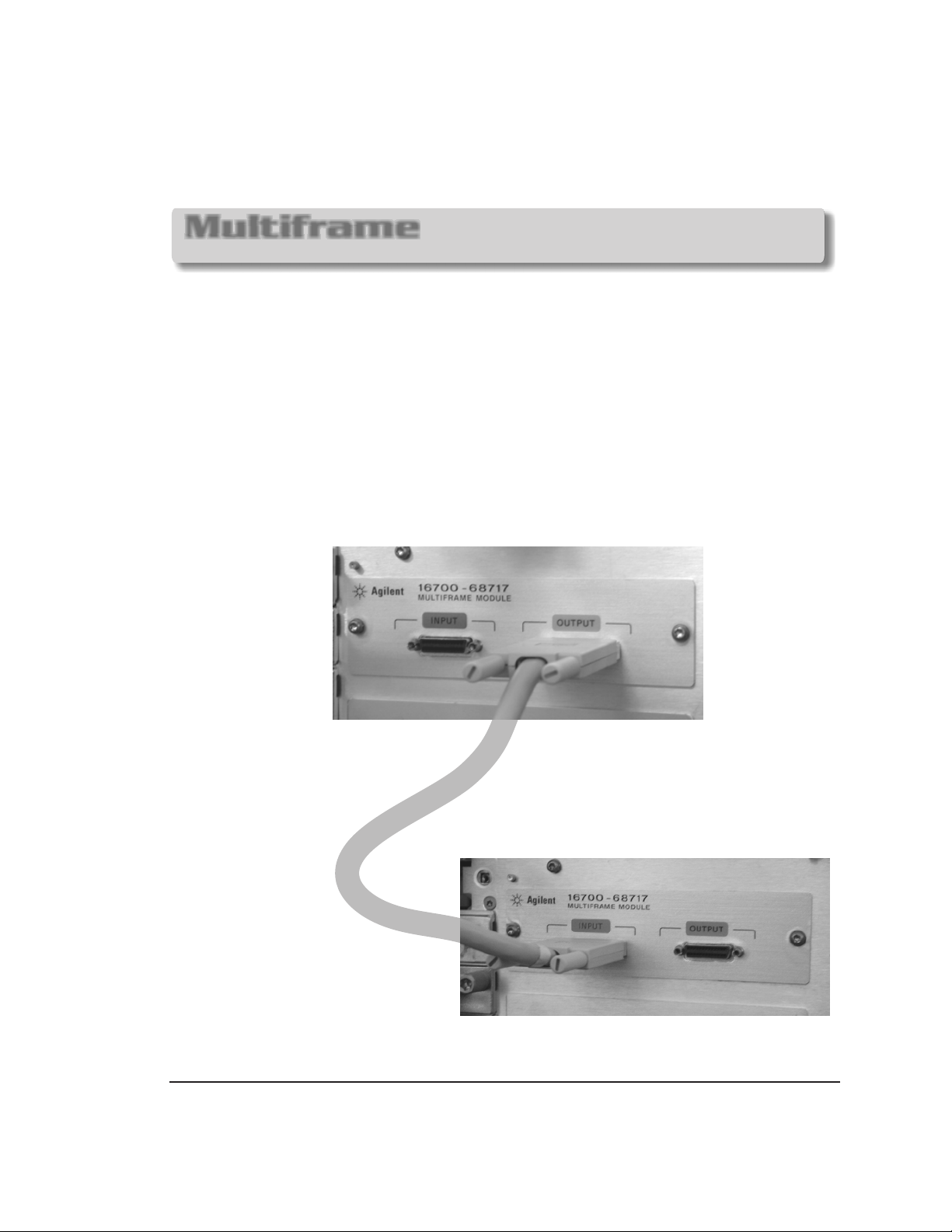
Multiframe
for 16700B/ 16702B
As many as eight 16700B’s and/or 16702B’s with
modules installed
The frame at the beginning of the series must have its port open and the
last frame in the series must have its port open.
Multiframe requires software Rev. A.02.00.00 or higher.
16702B logic analysis systems ordered with the multi
have the current operating system software installed.
may be connected together.
OUTPUT
Agilent 16700-68717 multiframe
INPUT
Agilent 16700B and
frame option installed will
16allp35
37

Multiframe
for 16700B/ 16702B
Install the Multiframe Modules into 16700B or 16702B frames.
CAUTION
Be sure to unplug the power cable before beginning this procedure.
1
16allp39
2
38

Multiframe
for 16700B/ 16702B
3
Multiframe Module
16allp40
4
39

Proper Cleaning
for 16700B/ 16702B/ all Measurement Modules
Instrument Cabinet and Module Front Panels
CAUTION
With the instrument unplugged, use mild soap and water to clean the cabinet of the
instrument or the front of the modules. Harsh soap might damage the water-based
paint. Do not immerse the instrument or modules in water.
16allp27
40

Measurement Modules
16517/18A
16522A
16533/34A
16557D
16710/11/12A
16715/16/17/18/19A
16720A
16750/51/52A
16533/34A
16557D 16522A
16710/11/12A
16720A
16715/
16/17/18/19A
for 16700A/B
16517/18A
16allp21
16702A/B
16701A/B

Measurement Modules
General Installation
Power
Busy
Power down
1
the system.
3
Remove
4
(Other or
or filler panels.
modules
filler panels.)
CAUTION
modules
5
Be sure the frame is unplugged before
removing or installing modules.
Disconnect the
2
power cable.
Insert
modules
or filler panels.
(Other or
modules
filler panels.)
CAUTION
Use a grounded wrist strap and mat when handling the . Gently apply pressure to
the center of the module or filler panel while tightening the thumb screws. Use filler panels in
empty slots for proper cooling.
Carefully slide the into the frame and hand tighten the thumb screws. If you are
inserting more than one , the tightening order is bottom to top .module module module
A single-module configuration can be installed in any available slot.
Some require calibration if they are moved to a different slot. For calibration
modules
information, refer to the online help for the individual .
modgen
module
modules
modules
42

16517A/18A
2-Card Module
Expander
2 Connector
OR
Cable
Master
Expander
Master
EXPANDER
MASTER
(16518A)
(16517A)
MASTER
EXPANDER
16517p08
2 Connector
Cable
(16517A)
(16518A)
43

16517A/18A
3-Card Module
Master
Expander
Expander
3 Connector
Cable
MASTER
EXPANDER
EXPANDER
16517p07
(16517A)
(16518A)
(16518A)
44

16517A/18A
3-Card Module
2 Connector
Cable
Expander
Master
Expander
2 Connector
EXPANDER
MASTER
EXPANDER
Cable
16517p06
(16518A)
(16517A)
(16518A)
45

16517A/18A
3-Card Module
Expander
Expander
Master
3 Connector
Cable
EXPANDER
EXPANDER
MASTER
16517p05
(16518A)
(16518A)
(16517A)
46

16517A/18A
4-Card Module
2 Connector
Cable
Expander
Master
Expander
Expander
3 Connector
EXPANDER
MASTER
EXPANDER
EXPANDER
Cable
16517p04
(16518A)
(16517A)
(16518A)
(16518A)
47

16517A/18A
4-Card Module
Expander
Expander
Master
Expander
3 Connector
Cable
2 Connector
EXPANDER
EXPANDER
MASTER
EXPANDER
Cable
16517p03
(16518A)
(16518A)
(16517A)
(16518A)
48

16517A/18A
5-Card Module
Expander
Expander
Master
Expander
Expander
3 Connector Cables
(Need 2)
EXPANDER
EXPANDER
MASTER
EXPANDER
EXPANDER
16517p02
(16518A)
(16518A)
(16517A)
(16518A)
(16518A)
49
16517/18
Done
Done

16522A
Single-Card Module
Each 16522A shipped stand alone has
the connected in the
2x10 cable
single-card module configuration.
2x10 cable
2x10 cable connection
for a single-card
16522p02
Master
J12 J11 J10 J9
CAUTION
J7 J8
A single-card module configuration can be
installed in any available slot.
Be sure the frame is unplugged before
removing or installing modules.
The following pages will show you how to
connect the to configure two,
three, four, and five-card modules.
2x10 cables
50

16522A
2-Card Module
EXPANDER
MASTER
2x10 Cable
Expander
Master
3-Card Module
Expander
J12 J11 J10 J9
J12 J11 J10 J9
EXPANDER
MASTER
EXPANDER
J12 J11 J10 J9
J7 J8
J7 J8
2x10 Cable
J7 J8
16522p03
Master
Expander
J12 J11 J10 J9
J12 J11 J10 J9
51
J7 J8
J7 J8

16522A
4-Card Module
Carefully slide the four cards half way into the mainframe slots.
Cable the bottom Expander to the Master Card first.
Cable the upper two Expanders to the Master Card.
Gently slide the cabled assembly fully into the frame and
tighten.
2x10 Cable
EXPANDER
EXPANDER
MASTER
EXPANDER
16522p04
Expander
Expander
Master
Expander
J12 J11 J10 J9
J12 J11 J10 J9
J12 J11 J10 J9
J12 J11 J10 J9
52
J7 J8
J7 J8
J7 J8
J7 J8

16522A
5-Card Module
Carefully slide the five cards half way into the mainframe slots.
Cable the bottom two Expanders to the Master first.
Cable the upper two Expanders to the Master.
Gently slide the cabled assembly fully into the frame and
tighten.
2x10 Cable
EXPANDER
EXPANDER
MASTER
EXPANDER
EXPANDER
Expander
Expander
Master
Expander
Expander
J12 J11 J10 J9
J12 J11 J10 J9
J12 J11 J10 J9
J12 J11 J10 J9
J12 J11 J10 J9
J7 J8
J7 J8
J7 J8
J7 J8
J7 J8
16522A
16522p05
53
Done
Done

16533/34A Calibration
Single-Card Module
Power down the mainframe.
1
Remove the module from the
2
mainframe and set the
PROTECTED / UNPROTECTED
switch to UNPROTECTED.
16702A/B
16600A Series
16700A/B
UNPROTECTED
PROTECTED
If you calibrate this module without unprotecting the memory, the new calibration settings will
not be saved when the system is shut down. The system will default to the previous settings.
The new calibration settings would be effective for the current active session only.
16533p01
54

16533/34A Calibration
Single-Card Module
Target
Out - Port - In
Out - Port - In
Target
Keyboard Mouse
Keyboard Mouse
Control
Control
RS232 Monitor Parallel Printer
RS232 Monitor Parallel Printer
SCSI-2Single Ended
LAN
LAN
10Base-T
10Base-T
SCSI-2Single Ended
LAN
LAN
10Base2
10Base2
Target
Target
Target
3
Target
Control
Control
Control
Control
To16701Expansion FrameTo16701 Expansion Frame
To16701Expansion FrameTo16701 Expansion Frame
Reinstall the 16533A/34A module
into the mainframe and reconnect
the power cable.
KeyboardKeyboard MouseMouse
KeyboardKeyboard MouseMouse
16533p02
Monitor power ON.
(If applicable)
4
5
55
16600A Series
System
power
ON
16700A/B
16702A/B

15
16533/34A Calibration
Single-Card Module
0
15
30
7
Connect the BNC Tee and the
(equal length) BNC cables to the
module.
For more accurate calibration, allow the system
6
30 minutes to warm up.
16533p03
56

16533/34A Calibration
Single-Card Module
Select -
16534A
>
16533p04
RUN
57

16533/34A Calibration
Single-Card Module
16533p05
58

16533/34A Calibration
Single-Card Module
Connect the BNC Tee, adapter, and
the (equal length) BNC cables to the
module.
16533p06
59

16533/34A Calibration
Single-Card Module
RUN
16533p07
Remember to set the PROTECTED/UNPROTECTED switch back to
PROTECTED.
If you just calibrated this card as one of a multi-card set, you must leave
the PROTECTED/UNPROTECTED switch in the UNPROTECTED position
until you have completed the multi-card calibration procedure on the
following pages.
Single Module
Calibration
Done
Done
60

16533/34A Calibration
Multi-Card Module
Each of the individual boards of a multi-card module must first be calibrated as a single.
(See previous pages: .)
The following example is of a two board arrangement. Up to four cards may be
configured in a 16700A, 16700B, 16702A, or 16702B mainframe.
Master
1
Connect the module cables.
Exit the current session and restart.
2
16533/34A Single-Card Module
1
2
3
16533p08
61

16533/34A Calibration
Multi-Card Module
3
Select -
16534A
>
4
Connect the (equal length) BNC calibration between channel 1, AC/DC cal,
5
and channel 1 of the second card. (Channel 1 of the third card next time etc.
up to four cards.)
Chan. 1
Chan. 1
Chan. 1Chan. 1
Chan. 1Chan.
Chan. 2
Chan. 2
Chan. 2Chan.
2
1
Chan. 2Chan.
2
16533p09
62

16533/34A Calibration
Multi-Card Module
7
6
RUN
Repeat steps 3 through 7 for
each additional card in your
multi-card module.
Select the appropriate
combination for each
additional card.
16533p10
63
Remember to set the
PROTECTED/UNPROTECTED
switch back to
PROTECTED.
Multi-Module
Calibration
Done
Done

16557D
Single-Card Module
When ordered as a single card, the 16557D is
shipped with the factory configured
as a single card module.
2x10 cable
2x10 Cable
2x10 Cable
Master
16557p03
J6J8 J5J7 J4
64
J3J9J10

16557D
2-Card Module
EXPANDER
MASTER
Find the required two connector
and connect the cables as shown.
2x25 Cables
(Need 2)
Expander
Master
Expander
2x25 cables
J8
Connect the on the
Expander to the Master.
2x10 cables
2x10 Cables
J6
J7
J5
J4
J3J9J10
Master
16557p04
J8
J7
65
J6
J5
J4
J3J9J10

16557D
3-Card Module
Find the required three connector
and connect the cables as shown.
2x25 cables
EXPANDER
MASTER
EXPANDER
Expander
Master
2x25 Cables
Expander
Master
Expander
J10
(Need 2)
J9
J8
J8
Connect the on the
Expanders to the Master.
2x10 cables
2x10 Cables
J6
J6
J5
J5
J4
J4
J7
J7
J3
J3J9J10
Expander
16557p05
J10
J9
J8
J7
66
J6
J5
J4
J3

16557D
4-Card Module
Find the required four connector
and connect the cables as shown.
2x25 Cables
(Need 2)
Expander
Expander
Master
Expander
Expander
J10
2x25 cables
J8
J9
EXPANDER
EXPANDER
MASTER
EXPANDER
Connect the on the
Expanders to the Master.
2x10 cables
2x10 Cables
J6
J7
J5
J4
J3
Expander
Master
Expander
16557p06
J10
J10
J9
J9
J8
J8
J8
J7
J7
J7
67
J6
J6
J6
J5
J5
J5
J4
J4
J4
J3
J3J9J10
J3

16557D
5-Card Module
Find the required five connector
and connect the cables as shown.
2x25 Cables
(Need 2)
Expander
Expander
Master
Expander
Expander
Expander
Expander
J10
J10
2x25 cables
J8
J9
J8
J9
Connect the on the
Expanders to the Master.
2x10 cables
2x10 Cables
J6
J6
J5
J5
J4
J4
J7
J7
EXPANDER
EXPANDER
MASTER
EXPANDER
EXPANDER
J3
J3
Master
Expander
Expander
16557p07
J10
J10
J9
J9
J8
J8
J8
J7
J7
J7
68
J6
J6
J6
J5
J5
J5
J4
J4
J4
J3J9J10
J3
J3

16710/ 11/ 12A
Single-Card Module
The 16700A, 16700B, 16702A and 16702B require Rev.
A.01.20.00 or higher. See the Software Installation chapter in
the book. Select 1660X-70XA.
A single 16710A, 16711A, and 16712A will have the cable
connected in the single-card configuration.
Master
2x40
J7
2x40 Cable
J9
J8
16710P01
69

16710/ 11/ 12A
Multi-Card Module
J5
Master
J6
2x40
Cable
J7
J9
J8
16710P03
2x25
Cable
J6
J5
Expander
2x25
Cable
70
J7
J9
J8
2x40
Cable

16710/ 11/ 12A
Multi-Card Module
J5
J5
Other modules or
filler panels.
J6 J7 J9
J6 J7 J9
J8
J8
16710P04
71
Multi-Card
Module
Done
Done

16715/ 16/ 17/ 18/ 19A 16750/ 51/ 52A
Single-Card Module
A single 16715/ 16/ 17/ 18/ 19A or 16750/ 51/ 52A will have the cable
connected in the single-card configuration.
Master
The require software Rev. A.01.40.00 or higher
16715/ 16/ 17A's .
J6J8 J5J7 J4
2x40
2x10 Cable
J3
16717p06
The 16718/ 19A's
The 16750/ 51/ 52A
See the Software Installation chapter in this book.
require software Rev. A.01.50.00 or higher.
require software Rev. A.02.00.00 or higher.
72

16715/ 16/ 17/ 18/ 19A
16750/ 51/ 52A
2-Card Module
Connect the of the Expander
to the Master.
Expander
Master
2x10 cable
2x40
Cable
Open the accessory pouch and
find two of the required
cables the
on the modules as shown.
. Connect
2x40
2x40 cables
J8
J8
EXPANDER
J7
J7
J6
J6
2x10 Cable
J5
J4
J5
J4
J3
J3
16717p05
2x40
Cable
2x40
Cable
MASTER
73

16715/ 16/ 17/ 18/ 19A
16750/ 51/ 52A
3-Card Module
Connect the of the Expanders to the Master. Find the in the
2x10 cables 2x40 cables
accessory pouch and connect them between the modules.
2x10 Cable
J6
J6
J6
J7
J5
J4
J5
J4
J5
J4
2x10 Cable
J8
J3
J3
J3
Expander
J7
J7
J7
J6
2x40
Cable
Expander
Master
Expander
2x40 Cable
2x40 Cable
J3
J8
J8
J8
J5
J4
16717p14
2x40 Cable
J3
J3
J4
J6
J5
J4
J6
J5
J8
J7
2x40 Cable
J8
J7
Master
2x40
Cable
Expander
74

16715/ 16/ 17/ 18/ 19A
16750/ 51/ 52A
4-Card Module
Connect the of the Expanders to the Master. Find the in the
2x10 cables 2x40 cables
accessory pouch and connect them between the modules.
2x10 Cables
J6
J7
J7
J7
J7
J5
J4
J6
J5
J4
J6
J5
J4
J6
J5
J4
J3
J3
J3
J3
2x10 Cable
J6
J8
J7
Expander
2x40
Cable
Expander
Expander
Master
Expander
2x40 Cable
2x40 Cable
2x40 Cable
J3
J8
J8
J8
J8
J5
J4
16717p13
2x40 Cable
J3
J4
J6
J5
J8
J7
Expander
2x40
2x40 Cable
J3
J4
J6
J5
J8
J7
Master
Cable
2x40 Cable
J3
J4
J6
J5
J8
J7
Expander
75
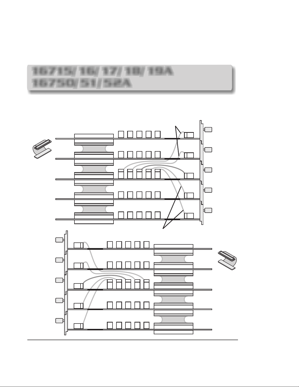
16715/ 16/ 17/ 18/ 19A
16750/ 51/ 52A
5-Card Module
Connect the of the Expanders to the Master. Find the in the
2x10 cables 2x40 cables
accessory pouch and connect them between the modules.
2x10 Cables
J7
J7
J7
J7
J7
J6
J6
J5
J6
J5
J6
J5
J6
J5
J6
J5
2x10 Cables
J8
J7
J4
J4
J4
J4
J4
J3
J3
J3
J3
J3
Expander
2x40
Cable
Expander
Expander
Master
Expander
Expander
2x40 Cable
2x40 Cable
2x40 Cable
2x40 Cable
J3
J8
J8
J8
J8
J8
J5
J4
16717p12
2x40 Cable
J3
J4
J6
J5
J8
J7
Expander
2x40
2x40 Cable
J3
J4
J6
J5
J8
J7
Master
Cable
2x40 Cable
J3
J4
J6
J5
J8
J7
Expander
2x40 Cable
J3
J4
J6
J5
J8
J7
Expander
76

16720A
Single-Card Module
Each 16720A shipped stand alone has
the connected in the
2x10 cable
single-card module configuration.
2x10 cable
2x10 cable connection
for a single-card
16720p02
Master
J13 J12 J11 J10
CAUTION
77
J9 J8
A single-card module configuration can be
installed in any available slot.
Be sure the frame is unplugged before
removing or installing modules.
The 16720A requires software Rev.
A.02.00.00 or higher.
The following pages will show you how to
connect the to configure two,
three, four, and five-card modules.
2x10 cables

16720A
2-Card Module
EXPANDER
MASTER
2x10 Cable
Expander
Master
3-Card Module
Expander
J13 J12 J11 J10
J13 J12 J11 J10
EXPANDER
MASTER
EXPANDER
J13 J12 J11 J10
J9 J8
J9 J8
2x10 Cable
J9 J8
16720p03
Master
Expander
J13 J12 J11 J10
J13 J12 J11 J10
78
J9 J8
J9 J8

16720A
4-Card Module
Carefully slide the four cards half way into the mainframe slots.
Cable the bottom Expander to the Master Card first.
Cable the upper two Expanders to the Master Card.
Gently slide the cabled assembly fully into the frame and
tighten.
2x10 Cable
EXPANDER
EXPANDER
MASTER
EXPANDER
16720p04
Expander
Expander
Master
Expander
J13 J12 J11 J10
J13 J12 J11 J10
J13 J12 J11 J10
J13 J12 J11 J10
79
J9 J8
J9 J8
J9 J8
J9 J8

16720A
5-Card Module
Carefully slide the five cards half way into the mainframe slots.
Cable the bottom two Expanders to the Master first.
Cable the upper two Expanders to the Master.
Gently slide the cabled assembly fully into the frame and
tighten.
2x10 Cable
EXPANDER
EXPANDER
MASTER
EXPANDER
EXPANDER
Expander
Expander
Master
Expander
Expander
J13 J12 J11 J10
J13 J12 J11 J10
J13 J12 J11 J10
J13 J12 J11 J10
J13 J12 J11 J10
J9 J8
J9 J8
J9 J8
J9 J8
J9 J8
16720A
16720p05
80
Done
Done

DECLARATION OF CONFORMITY
according to ISO/IEC Guide 22 and EN 45014
Manufacturer's Name:
Manufacturer's Address:
declares, that the product
Product Name:
Model Number(s):
Product Options(s):
Is in conformity with:
EMC:
IEC 61326-1:1997+A1:1998/EN 61326-1:1997+A1:1998
CISPR 11:1990 / EN 55011:1991 - Group 1, Class A*
IEC 61000-4-2:1995+A1:1998/EN 61000-4-2:1995 (ESD 4kV CD, 8kV AD)
IEC 61000-4-3:1995/EN 61000-4-3:1995 (3V/m 80% AM)
IEC 61000-4-4:1995/EN 61000-4-4:1995 (0.5kV line-line, 1kV line-earth)
IEC 61000-4-6:1996/EN61000-4-6:1996 (3V 80% AM, power line)
Australia/New Zealand: AS/NZS 2064.1
Safety:
IEC 61010-1:1990+A1:1992+A2:1995/EN61010-1:1994+A2:1995
Canada: CSA C22.2 No. 1010-1:1992
USA: UL 3111-1:1994
Agilent Technologies, Inc.
1900 Garden of the Gods Road
Colorado Springs, CO 80907 USA
Logic Analyzer System Mainframe
16700B, 16701B, 16702B
All options based on the above
Additional Information:
The product herewith complies with the requirements of the Low Voltage Directive 73/23/EEC
and the EMC Directive 89/336/EEC (including 93/68/EEC) and carries the CE marking accordingly.
(European Union)
*This product was tested in a typical configuration with Agilent Technologies test systems.
Date: 11/18/99
Ken Wyatt / Product Regulations Manager
For further information, please contact your local Agilent Technologies sales office, agent, or distributor.
dconframes

Definitions
Installation category (overvoltage category) Signal level, special equipment or parts of
equipment, telecommunication, electronic etc., with smaller transient overvoltages than
installation (overvoltage category)
II.
I:
Enviromental
Conditions
Temperature
Humidity
Power
Installation category (overvoltage category) Local level, appliances, portable
equipment etc., with smaller transient overvoltages than installation category
Indoor use only.
Altitude up to 3000 m. (10,000 ft.)
Instrument - 0 degrees C to 50 degrees C (32 degrees F to 122 degrees F)
Disk Media - 10 degrees C to 40 degrees C (50 degrees F to 104 degrees F)
Probes/cables - 0 degrees C to 65 degrees C (32 degrees F to 149 degrees F)
Relative humidity 8 to 80% at 40 degrees C (104 degrees F)
CAT , Pollution degree 2
II
All Frames: ~Line 115/230 volts ± 20%, 48-66 Hz, 610 Watts max.
II:
III.

DECLARATION OF CONFORMITY
according to ISO/IEC Guide 22 and EN 45014
Manufacturer's Name:
Manufacturer's Address:
Agilent Technologies
Colorado Springs Division
1900 Garden of the Gods Road
Colorado Springs, CO 80907 USA
declares, that the product
Product Name:
Model Number(s):
Measurement Modules
16517A, 16518A, 16522A, 16533A, 16534A,
16557D, 16710A, 16711A, 16712A, 16715A,
16716A, 16717A, 16718A, 16719A
Product Options(s):
All
conforms to the following Product Specifications:
Safety:
IEC 1010-1:1990+A1 / EN 61010-1:1993
UL 3111
CSA-C22.2 No. 1010.1:1993
EMC:
CISPR 11:1990 / EN 55011:1991 Group 1, Class A
IEC 801-2:1991 / EN 50082-1:1992 4 kV CD, 8 kV AD
IEC 801-3:1984 / EN 50082-1:1992 3 V/m,{1kHz 80% AM, 27-1000 MHz}
IEC 801-4:1988 / EN 50082-1:1992 0.5 kV Sig. Lines, 1kV Power Lines
Supplementary Information:
The product herewith complies with the requirements of the Low Voltage Directive 73/23/EEC
and the EMC Directive 89/336/EEC, and carries the CE marking accordingly.
This product was tested in a typical configuration with Agilent Technologies test systems.
Colorado Springs, 10/03/96
Ken Wyatt / Product Regulations Manager
For further information, please contact your local Agilent Technologies sales office, agent, or distributor.
dconoldmods

Definitions
Installation category (overvoltage category) Signal level, special equipment or parts of
equipment, telecommunication, electronic etc., with smaller transient overvoltages than
installation (overvoltage category)
II.
I:
Enviromental
Conditions
Temperature
Humidity
Power
Installation category (overvoltage category) Local level, appliances, portable
equipment etc., with smaller transient overvoltages than installation category
Indoor use only.
Altitude up to 3000 m. (10,000 ft.)
Instrument - 0 degrees C to 50 degrees C (32 degrees F to 122 degrees F)
Disk Media - 10 degrees C to 40 degrees C (50 degrees F to 104 degrees F)
Probes/cables - 0 degrees C to 65 degrees C (32 degrees F to 149 degrees F)
Relative humidity 8 to 80% at 40 degrees C (104 degrees F)
(From host frame.)
II:
III.

DECLARATION OF CONFORMITY
According to ISO/IEC Guide 22 and CEN/CENELEC EN 45014
Manufacturer's Name:
Manufacturer's Address:
declares, that the product
Product Name:
Model Number(s):
Product Options(s):
Is in conformity with:
EMC:
IEC 61326-1:1997+A1:1998/EN 61326-1:1997+A1:1998
CISPR 11:1990 / EN 55011:1991 - Group 1, Class A*
IEC 61000-4-2:1995+A1:1998/EN 61000-4-2:1995 (ESD 4kV CD, 8kV AD)
IEC 61000-4-3:1995/EN 61000-4-3:1995 (3V/m 80% AM)
IEC 61000-4-4:1995/EN 61000-4-4:1995 (0.5kV line-line, 1kV line-earth)
IEC 61000-4-6:1996/EN61000-4-6:1996 (3V 80% AM, power line)
Australia/New Zealand: AS/NZS 2064.1
Safety:
IEC 61010-1:1990+A1:1992+A2:1995/EN61010-1:1994+A2:1995
Canada: CSA C22.2 No. 1010-1:1992
USA: UL 3111-1:1994
Agilent Technologies, Inc.
1900 Garden of the Gods Road
Colorado Springs, Colorado 80907 USA
Measurement Modules
16720A, 16750A, 16751A, and 16752A
All options based on the above
Additional Information:
The product herewith complies with the requirements of the Low Voltage Directive 73/23/EEC
and the EMC Directive 89/336/EEC (including 93/68/EEC) and carries the CE marking accordingly.
(European Union)
*This product was tested in a typical configuration with Agilent Technologies test systems.
Date: 02/08/2000
Ken Wyatt / Product Regulations Manager
For further information, please contact your local Agilent Technologies sales office, agent, or distributor.
dconnewmods

Definitions
Installation category (overvoltage category) Signal level, special equipment or parts of
equipment, telecommunication, electronic etc., with smaller transient overvoltages than
installation (overvoltage category)
II.
I:
Enviromental
Conditions
Temperature
Humidity
Power
Installation category (overvoltage category) Local level, appliances, portable
equipment etc., with smaller transient overvoltages than installation category
Indoor use only.
Altitude up to 3000 m. (10,000 ft.)
Instrument - 0 degrees C to 50 degrees C (32 degrees F to 122 degrees F)
Disk Media - 10 degrees C to 40 degrees C (50 degrees F to 104 degrees F)
Probes/cables - 0 degrees C to 65 degrees C (32 degrees F to 149 degrees F)
Relative humidity 8 to 80% at 40 degrees C (104 degrees F)
(From host frame.)
II:
III.

C
Copyright
Agilent Technologies Inc. 2000
All Rights Reserved.
Reproduction, adaptation, or
translation without prior written
permission is prohibited, except
as allowed under the copyright
laws.
Restricted Rights Legend.
Use, duplication or disclosure by
the U.S.Government is subject to
restrictions as set forth in
subparagraph (c)(1)(ii) of the
Rights in Technical Data and
Computer Software clause at
DFARS 252.227-7013.
Agilent Technologies
3000 Hanover Street
Palo Alto, California 94304
U.S.A.
Rights for no- DOD U.S.
Government Departments and
Agencies are set forth in FAR
52.227-19(c) (1,2).
Inc.
Document Warranty
The information contained in this
document is subject to change
without notice.
Agilent Technologies Inc. makes
no warranty of any kind with
regard to this material,
including, but not limited to,
the implied warranties of
merchantability or fitness for a
particular purpose.
Agilent Technologies Inc. shall
not be liable for errors contained
herein or for damages in
connection with the furnishing,
performance, or use of this
material.
Safety
This apparatus has been designed
and tested in accordance with IEC
Publication 1010, Safety
Requirements for Measuring
Apparatus, and has been supplied
in a safe condition. This is a
Safety Class I instrument
(provided with terminal for
protective earthing). Before
applying power, verify that the
correct safety precautions are
taken (see the following
warnings). In addition, note the
external markings on the
instrument that are described
under "Safety Symbols."
Warning
Before turning on the
instrument, you must connect the
protective earth terminal of the
instrument to the protective
conductor of the (mains) power
cord. The mains plug shall only
be inserted in a socket outlet
provided with a protective earth
contact. You must not negate the
protective action by using an
extension cord (power cable)
without a protective conductor
(grounding). Grounding one
conductor of a two-conductor
outlet is not sufficient protection.
Only fuses with the required
rated current, voltage, and
specified type (normal blow, time
delay, etc.) should be used. Do
not use repaired fuses or shortcircuited fuseholders. To do so
could cause a shock or fire
hazard.
Service instructions are for
trained service personnel. To
avoid dangerous electric shock,
do not perform any service unless
qualified to do so. Do not
attempt internal service or
adjustment unless another person,
capable of rendering first aid and
resuscitation, is present.
If you energize this instrument
by an auto transformer (for
voltage reduction), make sure the
common terminal is connected to
the earth terminal of the power
source.
Whenever it is likely that the
ground protection is impaired,
you must make the instrument
inoperative and secure it against
any unintended operation.
Do not operate the instrument
in the presence of flammable
gasses or fumes. Operation of
any electrical instrument in such
an environment constitutes a
definite safety hazard.
Do not install substitute parts or
perform any unauthorized
modification to the instrument.
Capacitors inside the instrument
may retain a charge even if the
instrument is disconnected from
its source of supply.
Use caution when exposing or
handling the CRT. Handling or
replacing the CRT shall be done
only by qualified maintenance
personnel.
Safety Symbols
Instruction manual symbol: the
product is marked with this
symbol when it is necessary for
you to refer to the instruction
manual in order to protect against
damage to the product.
Hazardous voltage symbol.
Earth terminal symbol: Used to
indicate a circuit common
connected to grounded chassis.
WARNING
The Warning sign denotes a
hazard. It calls attention to a
procedure, practice, or the like,
which, if not correctly performed
or adhered to, could result in
personal injury. Do not proceed
beyond a Warning sign until the
indicated conditions are fully
understood and met.
CAUTION
The Caution sign denotes a
hazard. It calls attention to an
operating procedure, practice, or
the like, which, if not correctly
performed or adhered to, could
result in damage to or destruction
of part or all of the product. Do
not proceed beyond a Caution
symbol until the indicated
conditions are fully understood or
met.
Agilent Technologies
P.O. Box 2197
1900 Garden of the Gods Road
Colorado Springs, CO. 80901

Product Warranty
Agilent Technologies
This Inc.
product has a warranty against
defects in material and
workmanship for a period of one
year from date of shipment. Some
newly manufactured
Technologies Inc.
contain remanufactured parts which
are equivalent to new in
performance. During the warranty
Agilent Technologies Inc.
period,
will, at its option, either repair or
replace products that prove to be
defective.
For warranty service or repair, this
product must be returned to a
service facility designated by
Agilent Technologies Inc.
For products returned to
Technologies Inc.
service, the Buyer shall prepay
shipping charges to
Technologies Inc. Agilent
Technologies Inc.
shipping charges to return the
product to the Buyer. However, the
Buyer shall pay all shipping
charges, duties, and taxes for
products returned to
Technologies
Agilent Technologies warrants that
its software and firmware
designated by Agilent Technologies
for use with an instrument will
execute its programming
instructions when properly installed
on that instrument. Agilent
Technologies does not warrant that
the operation of the instrument
software, or firmware will be
uninterrupted or error free.
Agilent
products may
Agilent
for warranty
Agilent
and
shall pay
Agilent
from another country.
No other warranty is
expressed or implied.
TechnologiesInc.
Agilent
specifically
disclaims the implied
warranties of
merchantability or fitness for
a particular purpose.
Exclusive Remedies
The remedies provided herein are
the buyer's sole and exclusive
Agilent Technologies
remedies.
Inc.
shall not be liable for any
direct, indirect, special, incidental,
or consequential damages, whether
based on contract, tort, or any
other legal theory.
Assistance
Product maintenance agreements
and other customer assistance
agreements are available for
Agilent Technologies Inc.
products. For any assistance,
contact your nearest
Technologies
Agilent
Sales Office.
Certification
Agilent Technologies Inc.
that this product met its published
specifications at the time of
shipment from the factory.
Technologies Inc.
that its calibration measurements
are traceable to the United States
National Institute of Standards and
Technology, to the extent allowed
by the Institute's calibration
facility, and to the calibration
facilities of other International
Standards Organization members.
certifies
Agilent
further certifies
About this edition
Publication number
16700-97014, Apr. 2000
Printed in USA.
New editions are complete
revisions of the manual. Many
product updates do not require
manual changes; and, conversely,
manual corrections may be done
without accompanying product
changes. Therefore, do not expect
a one-to-one correspondence
between product updates and
manual updates.
Limitation ofWarranty
The foregoing warranty shall not
apply to defects resulting from
improper or inadequate
maintenance by the Buyer, Buyersupplied software or interfacing,
unauthorized modification or
misuse, operation outside of the
environmental specifications for the
product, or improper site
preparation or maintenance.
 Loading...