

Page 1

Processor and Bus Support for Agilent Technologies Logic Analyzers
Configuration Guide
Tools to Accelerate Your Debugging Process
May 1, 2000
Configuring a logic analysis system for your specific
application is as easy as one, two, three. To configure a
system you must select products that will 1. Probe,
2. Acquire, and 3. Analyze the data from your system.
The following figure gives a quick overview of typical
system considerations.
Use the information in each of the sections listed to help
you configure a system that will meet your specific measurement needs.
Accurate measurements start with reliable
probing. Agilent Technologies offers a wide
variety of probing accessories to support your
measurement needs making it easy to connect
your Agilent logic analyzer to your designs.
3. Analysis
View and analyze data in a form
you easily understand to help
debug problems faster
1. Probing
The physical and electrical
connection to target signals
2. Acquisition
Data capture, stimulus
and processor control
Probing Adapters
• General Purpose Lead Set
• High-density termination adapters
• Processor specific analysis probes
Frames with built-in acquisition
or measurement modules
• State/Timing Analyzers
• Oscilloscopes
• Pattern Generators
Analysis Tools
• Post-processing Tool sets
• Debuggers
Table of Contents
Probing . . . . . . . . . . . . . . . . . . . . . . . . . . . . . . . . . . . . .pg 2
• General Purpose . . . . . . . . . . . . . . . . . . . . . . . . . . . . . .pg 2
• Custom Probing . . . . . . . . . . . . . . . . . . . . . . . . . . . . . . .pg 3
• TQFP, PQFP Adapters . . . . . . . . . . . . . . . . . . . . . . . . . .pg 4
• Device Specific –
Processors, DSPs, Busses, etc . . . . . . . . . . . . . . . . .pg 5
Logic Analysis Systems
(Acquisition) . . . . . . . . . . . . . . . . . . . . . . . . . . . . . . . . . . . . . .pg 8
• 16700 series frames . . . . . . . . . . . . . . . . . . . . . . . . . . .pg 9
• Measurement modules . . . . . . . . . . . . . . . . . . . . . . .pg 11
• 1670 Benchtops . . . . . . . . . . . . . . . . . . . . . . . . . . . . . . .pg 14
Analysis Tools . . . . . . . . . . . . . . . . . . . . . . . . . . . . . . . . . . . .pg 15
• Application Software . . . . . . . . . . . . . . . . . . . . . . . . . .pg 15
• Debuggers . . . . . . . . . . . . . . . . . . . . . . . . . . . . . . . . . . .pg 16
Example System Configuration . . . . . . . . . . . . . . . . . . . . .pg 17
uP and Bus Support Matrix . . . . . . . . . . . . . . . . . . . . . . .pg 18
Old to New Model Number
Compatibility Table . . . . . . . . . . . . . . . . . . . . . . . . . . . . . . . .pg 53
Third Party Contact Information . . . . . . . . . . . . . . . . . . . .pg 54
Page 2

2
How To Determine Your Probing
Needs
To determine what probing method is best to use you
need to evaluate your needs and take the following into
consideration:
• Number of signals to be probed
• Ability to design probing connectors into the target
• Probing clearance requirements
• Available probing devices
• Signal loading
• Ease of installation
• Package type
• DIP Dual Inline Package
• PGA Pin Grid Array
• BGA Ball Grid Array
• PLCC Plastic Leaded Chip Carrier
• PQFP Plastic Quad Flat Pack
• TQFP Thin Quad Flat Pack
• Package Pin Pitch (distance between centers of
adjoining pins)
• Pin count
Probing Options:
General purpose: Use as a convenient way to access
individual signals anywhere on the target.
Custom Probing - Designed Into the Target: Consider
placing probing connectors directly on the target during board layout. Design for testability. (See pg 3)
IC Package Adapters: Simple means of connecting to
all the pins of a PQFP or TQFP package. (See pg 4)
Device Specific: Probe devices specifically designed
for processors, DSPs, busses, and programmable logic
devices. (See pg 5)
Number of Pin Pitch Agilent Product # Number of Agilent
Signals Wedges Included
3 0.5 mm E2613A 1
3 0.5 mm E2613B 2
8 0.5 mm E2614A 1
16 0.5 mm E2643A 1
3 0.65 mm E2615A 1
3 0.65 mm E2615B 2
8 0.65 mm E2616A 1
16 0.65 mm E2644A 1
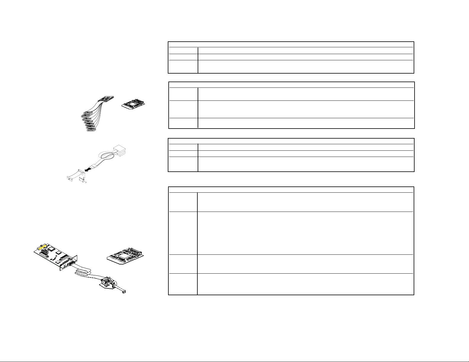
The Agilent Technologies wedge probe
The Agilent wedge probe adapter provides
mechanically sound, noninvasive connection to
adjacent pins on TQFP and PQFP packages. Connect logic analyzer flying leads directly to the
adapter; connect scope probes through a dualhead adapter.
Probing – General Purpose
1
2
3
Electrical connection to pins
Electrical connection
between conductors
Two contact
points on
each leg
General Purpose Lead Set: 01650-61608
Page 3

3
You can design test connections into your circuit using
test headers with termination adapters. Details of how
to do this are shown in Probing Solutions for Agilent
TechnologiesLogic Analysis Systems, publication number 5968-4632E.
Agilent Product Number Description
E5346A High-Density Termination Adapter
E5351A High-Density Adapter
E5346-44701 Recommended Support Shroud
E5346-60002 High Speed Mictor Break-out Adapter
E5346-68701 Five Mictor Connectors and Five Support Shrouds
Product Number Description
01650-63203 Standard Termination Adapter
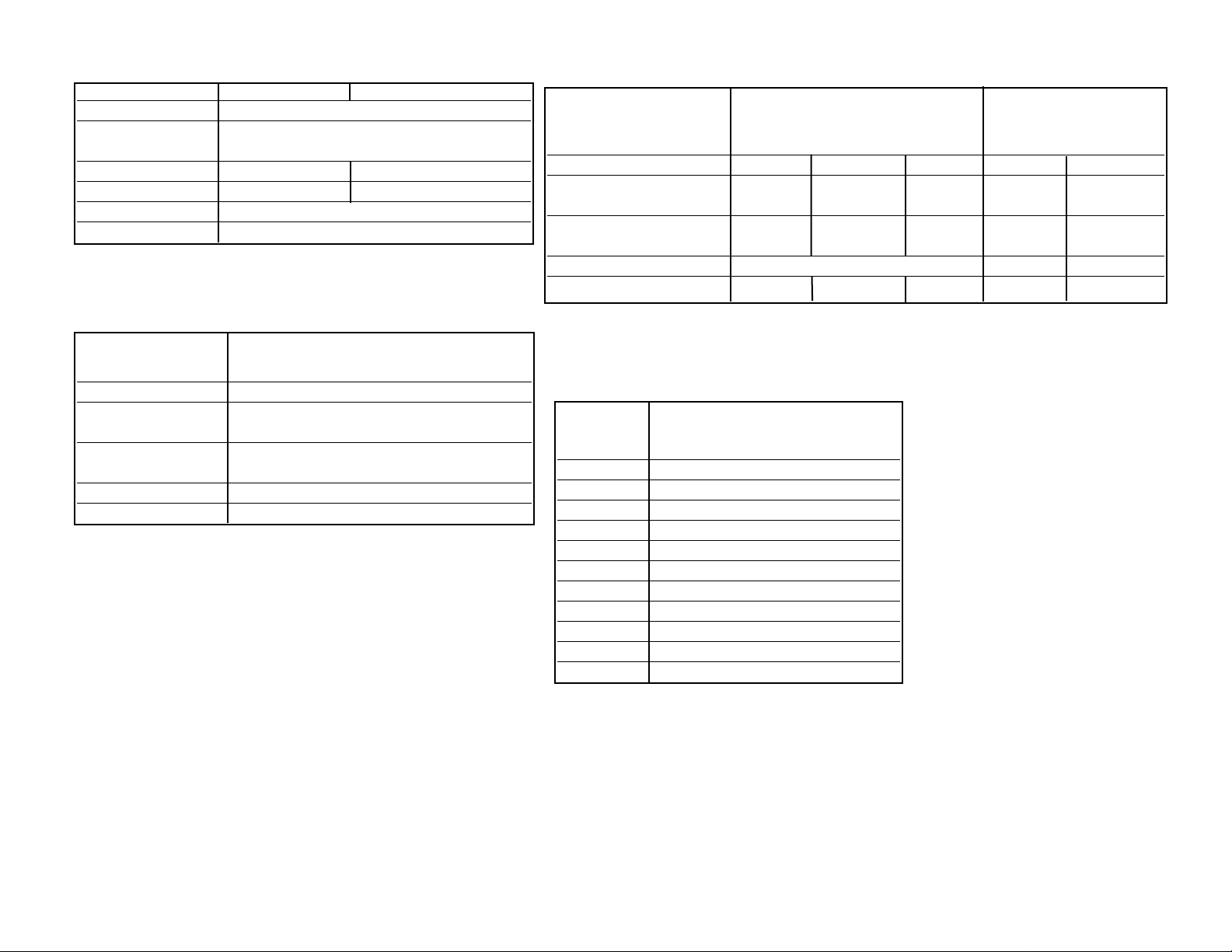
Agilent E5346A High-
density termination
adapter
32 data channels
2 clock channels
Mictor Connectors for High-
density termination adapters
01650-63203
16 data channels
1 clock channel
Probing – Custom Probing (Designed into the Target System)
Designing a Probing Solution for Unique Applications
Page 4

Probing – TQFP, PQFP Adapters
Elastomeric Probe Adapter
Package Pin Pitch Elastomeric Probe 1/4 Flex Adapter
Adapter
144-pin TQFP 0.5 mm E5336A E5340A
144-pin PQFP/CQFP 0.65 mm E5361A E5340A
160-pin QFP 0.5 mm E5377A E5349A
160-pin PQFP/CQFP 0.65 mm E5373A E5349A
176-pin TQFP 0.5 mm E5348A E5349A
208-pin PQFP/CQFP 0.5 mm E5374A E5371A
240-pin PQFP/CQFP 0.5 mm E5363A E5371A
Agilent Technologies’ state-of-the-art probe adapters
offer a simple means of connecting to PQFP and TQFP
packages with minimal “keep out” area. Agilent’s reliable probes ensure trouble-free electrical and mechanical connection.
1/4 Flex
Adapter
Elastomeric
Probe
Locator
(included with
Elastomeric
Probe)
4
Page 5

5
This document lists available processor and bus support products from Agilent Technologies and complimentary vendors. Agilent and our partners provide an
extensive range of quality tools that offer non-intrusive,
full-speed, real-time analysis and processor execution
control to accelerate your debugging process. The following steps help you to determine the necessary products to meet your specific measurement needs.
Simply:
1. Determine if your device is supported (pg 5)
2. Select the products that meet your measurement
needs (pg 5)
3. Verify analyzer support and compatibility (pg 8)
The following provides information on how to use the
matrix starting on page 18 to accomplish each step.
1. Determine if your device is supported
• Use the “Device Coverage” section of the matrix
to find your processor, controller, bus, or programmable logic device. Processors are listed
alpha-numerically, except for Intel and
Motorola, where processors are grouped by
family.
• The value in the ‘Max Bus Clk MHz’ column
refers to the maximum supported external bus
speed for the processor. In most cases this is not
the speed of the processor.
Example: Pentium with MMX has core speeds up
to 233 MHz, but the external bus speed is 66 MHz.
• Supported package types are listed. In some
cases an inverse assembler is separately
available when the probing can be designed into
the target. Check the notes for available probing
application notes and product literature for
clearance requirements and target
considerations.
Contact Agilent Technologies if you do not see support
for your specific device . A sales representative can:
• determine if support is under development
• recommend third parties that design custom
solutions
• direct you to information on how to design a test
solution (refer to the probing section in this
document)
2. Select the product(s) that meet your measurement
needs.
The “Product Information” section of the matrix lists
the available products for each device. The diagrams
and tables on pages 6-7 give a high level overview of
what each product type includes, provides, and
requires as well as specifying compatibility.
The following describes the different measurement
modes.
Timing –Data is sampled at regular intervals by the
analyzer’s internal clock. The captured trace is displayed as waveforms (asynchronous).
State – Clocking is supplied by the system under test
and captured data is displayed as a sequential listing of
logical states (synchronous). Included inverse assemblers convert the real-time trace into processor
mnemonics.
Enhanced Inverse Assembler –Provides advanced filtering capabilities such as removal of unexecuted
prefetches and certain cycle types. The specific filtering capabilities are processor dependent. Refer to the
product literature for details.
Emulation – The product provides processor control
including break, run, reset and single step, code download, and register/memory modification.
Setup Assistant – A menu driven interface that guides
you through connecting and configuring a processor
measurement. This feature is available on the Agilent
16600A and 16700 series frames.
Contact Agilent or the Appropriate Third Party for Your
Selections
Contact an Agilent Technologies sales representative
to order the products you have selected or to obtain
more information. Agilent sales information as well as
third-party contact information is listed on pg 54.
Product Type
3rd
Party
Vendor or
Agilent
Product
Number
Setup Assist
Emulation
Enhanced IA
State
Timing
Product Information
Probing – Device Specific
(Processors, DSPs, Controllers, Busses, and Programmable Logic Devices)
Device
Manufacturer or
Architecture and
Name
Max
Bus
Clk
MHz
Pin
Count,
Pkg Type
Device Coverage
Page 6
6
Analysis Probes
(Formerly called Preprocessors)
Real-Time Trace Products
Inverse Assembler
Includes • Inverse assembler software
Provides • Converts real-time trace into processor mnemonics
Requires • Method for connecting to the processor either through the general purpose probes or through
connectors designed onto the target
N-Trace Analysis Probe
Includes • E5346A cable, JTAG breakout board and configuration software
Provides • Runtime trace information through special messages (status) and data
Requires • Agilent 16600A or 16700 series frame with appropriate state/timing module
• Debugger (available on your platform from third party)
Inverse Assembler
Software that converts
a captured state trace
into processor
mnemonics.
Emulation Solution
Option required to specify processor package type
(Bundle of processor products for easier ordering and
configuration. Works with the Agilent 16600A and
16700 series logic analyzers).
Emulation Solution
Includes • Agilent B4620B Source Correlation tool set
• Analysis Probe with any necessary package adapters and Inverse Assembler
• Emulation Module
Provides • Correlation of real-time trace to high level source code
• Ability to set the logic analyzer trigger by clicking a line of source code
• Real-time trace acquired in state and/or timing (supported modes of operation
varies, check table for specific processor)
• Processor control including break, run, reset and single step
• Code download
• Register/memory modification
Requires • “A” versions require Agilent 16600A or 16700 series frame with an available emulation module slot
• “B” versions require an Agilent 16700 Series frame with an available emulation module slot.
• Option to specify processor package type.
Compatibility • Debugger (available on your platform from a third party)
• “A” versions work with Agilent 16600A and 16700 standard Emulation Control Interface
• “B” versions work with Agilent 16700 standard Emulation Control Interface
Emulation Solution
Analysis Probe
Includes • Inverse assembler (for analysis probes that support state mode) and configuration files
• Analysis probe hardware (unless specified as inverse assembler only)
Provides • Mechanical and electrical connection to the processor or bus
• Real-time trace acquired in state and/or timing (supported modes of operation varies, check matrix for
specific processor)
Requires • Appropriate logic analyzer channel count (refer to matrix)
N-Trace Analysis Probe
Page 7

7
Emulation Products
Emulation Probe - Agilent E5900A/B
(Formerly called Processor Probe or Software Probe)
Option required to specify processor family
Emulation Probe- Agilent E5900A/B
Includes • Standalone emulation probe, Target Interface Module (TIM), cables and firmware
Provides • Processor control including break, run, reset and single step
• Code download
• Register/memory modification
Requires • Option to specify processor family
Compatibility • Debugger (available on your platform from third party)
• E5900A works with Agilent 16600A and 16700 standard Emulation Control Interface
• E5900B works with Agilent 16700 standard Emulation Control Interface
• Controlled over LAN
Emulation Module- Agilent E5901A/B
Includes • Emulation Module, Target Interface Module (TIM), cables and firmware
Provides • Processor control including break, run, reset and single step
• Code download
• Register/memory modification
Requires • E5901A works with Agilent 16600A and 16700 series mainframes with an available
emulation module slot
• E5901B works with Agilent 16700 series mainframe with an available
emulation module slot
• Option to specify processor family
Compatibility • Debugger (available on your platform from third party)
• E5901A works with Agilent 16600A and 16700 standard Emulation Control Interface
• E5901B works with Agilent 16700 standard Emulation Control Interface
Emulation Module - Agilent E5901A/B
Option required to specify processor family
Emulation Migration - Agilent E5902A/B
Option required to specify processor family
Emulation Migration- Agilent E5902A/B
Includes • Target Interface Module (TIM), cables and firmware
Provides • Processor personality change for existing emulation module or probe
Requires • Existing emulation module or probe
• Option to specify processor family
Trace port analyzer- Agilent E5903A
Includes • Trace port analyzer module, Target Interface Module (TIM), power supply, and cables
Provides • Runtime trace information through special messages (status) and data
Requires • Emulation probe or emulation module
Compatibility • Debugger (available on your platform from third party)
Trace port analyzer - Agilent E5903A
Option required to specify processor family
E5900A
E5900B
E5901A
E5901B
E5902A
E5902B
Page 8

3. Verify analyzer support/compatibility
Use the “Logic Analyzer Support” section of the matrix
to determine compatibility between the processor
support product(s) you have selected and an existing
analyzer to decide which frame and/or modules to purchase.
• The matrix lists a minimum and maximum number
of pods for analyzing a device. The minimum pod
count provides enough signals for the inverse
assembler to interpret the captured data and
display processor mnemonics. The maximum pod
count provides access to additional signals that
could be useful during system debug.
Example: The MPC860 BGA shows 6/12 which means
the analysis probe requires 6 pods for inverse
assembly. Six additional pods (for a total of twelve
pods) could be used for analysis of additional signals.
• The analyzer support recommendations are based
on the minimum pod count required for inverse
assembly. Two methods are used for signifying
analyzer support. A number represents the
number of modules required. A check mark (√)
signifies the analyzer has enough built-in
acquisition channels to meet the minimum pod
requirements.
Your mainframe and measurement module selection
depends on:
• Number of analysis channels needed
• Optional measurement ability
• Future expansion capability
• Emulation requirements
• Form factor
• Budget
Frame offerings:
Agilent Technologies 16700B Series (pg 9): 5 Slot modular frame with expansion capability, supports 1
emulation module or 1 multiframe module.
Agilent Technologies 16700A Series (pg 10): 5 slot modular frame with expansion capability, supports 2
emulation modules.
Agilent Technologies 1670G Series (pg 14): Benchtop analyzer with built-in acquisition. Choices include logic
analyzer, logic analyzer with integrated pattern generator, and logic analyzer with integrated oscilloscope.
Versions of each vary by channel count.
High level details are provided in this document for the logic analysis systems and modules. If more
information is needed, please obtain the following documents.
Logic Analysis Systems (Acquisition)
Agilent Technologies Product Literature
Agilent Technologies 16700 Series Logic Analysis System 5968-9661E
1670G Series Benchtops 5968-6421E
16557
16550,16710/1/2
16715/6/7/8/9
1673
1672
1671
1670
Min #
Pods
for
IA /
Max #
Pods
16700A/B Series
with ...
16603
16602
16601
16600
Logic Analyzer Support
16600A
Series
1670G Series
16550
16500C
with ...
16557
Products Discontinued
Agilent Technologies
8
Page 9

Agilent 16702B
Agilent 16700B
Agilent 16701B
Agilent Technologies 16700B Series Mainframes
Agilent Model Number Agilent 16702B
Display 12.1” 800x600 Color Flat Panel Display with touchscreen
Built-in Analysis Channels None – Requires measurement modules
Supports Expansion frame Yes – Agilent 16701A or 16701B
Available Measurement Module slots 5 (Total of 10 with Agilent 16701A or 16701B expansion frame)
Available Emulation Module slots 1 (Total of 3 with 16701A or 16701B expansion frame)
Internal System RAM 128 Mbyte standard
Supported Monitor Resolution 1280 x 1024 standard
Mass Storage 9 Gbyte hard disk drive, 1.44 Mbyte DOS formatted floppy drive
CD Rom Drive 40X Built-in standard
Agilent Model Number Agilent16700B
Display Monitor sold separately
Built-in Analysis Channels None – Requires measurement modules
Supports Expansion frame Yes – Agilent 16701A or 16701B
Available Measurement Module slots 5 (Total of 10 with Agilent 16701A or 16701B expansion frame)
Available Emulation Module slots 1 (Total of 3 with 16701A or 16701B expansion frame)
Internal System RAM 128 Mbyte standard
Supported Monitor Resolution 1280 x 1024 standard
Mass Storage 9Gbyte hard disk drive, 1.44 Mbyte DOS formatted floppy drive
CD Rom Drive 40X Built-in standard
Agilent Model Number Agilent16701B
(Requires Agilent 16702A, 16702B, 16700A, or 16700B)
Display N/A
Built-in Analysis Channels None – Requires measurement modules
Supports Expansion frame N/A
Available Measurement Module slots 5
Available Emulation Module slots 2
9
0B
B
Page 10

10
Agilent 16702A
Agilent 16700A
Agilent 16701A
Agilent Technologies 16700A Series Mainframes
Agilent Model Number Agilent 16702A
Display 10.3” 800x600 Color Flat Panel Display
Built-in Analysis Channels None – Requires measurement modules
Supports Expansion frame Yes – Agilent 16701A or 16701B
Available Measurement Module slots 5 (Total of 10 with Agilent 16701A or 16701B expansion frame)
Available Emulation Module slots 2 (Total of 4 with 16701A or 16701B expansion frame)
Internal System RAM 64 Mbyte standard
Supported Monitor Resolution 1280 x 1024 standard
Mass Storage 4 Gbyte hard disk drive, 1.44 Mbyte DOS formatted floppy drive
CD Rom Drive Available via Option #004
Agilent Model Number Agilent16700A
Display Monitor sold separately
Built-in Analysis Channels None – Requires measurement modules
Supports Expansion frame Yes – Agilent 16701A or 16701B
Available Measurement Module slots 5 (Total of 10 with Agilent 16701A or 16701B expansion frame)
Available Emulation Module slots 2 (Total of 4 with 16701A or 16701B expansion frame)
Internal System RAM 64 Mbyte standard
Supported Monitor Resolution 1280 x 1024 standard
Mass Storage 4Gbyte hard disk drive, 1.44 Mbyte DOS formatted floppy drive
CD Rom Drive Available via Option #004
Agilent Model Number Agilent16701A
(Requires Agilent 16702A, 16702B, 16700A, or 16700B)
Display N/A
Built-in Analysis Channels None – Requires measurement modules
Supports Expansion frame N/A
Available Measurement Module slots 5
Available Emulation Module slots 2
0B
B
Page 11

11
Option Number Description
#001 Add 17”, 1280x1024 Monitor and cable
#003 4 Mbyte video RAM supports up to 1600x1200
resolution, 256 Mbyte system RAM
(Only available at time of frame purchase)
#004* Add external CD-ROM Drive and cable
(Agilent 16700A series frames only)
#008 186 B External data drive
#009 External removable hard drive
#012 Multi-frame module for correlating
multiple frames
#0B3 Service Manual
#1CM Rackmount Kit for 16700A, 16702A, 16700B
#AXC Rackmount Kit for 16702B
Agilent 16700A Series Logic Analysis Systems Options
Measurement Agilent Description
Module Category Model Number
State and Timing 16719A* 333 MHz state, 667 MHz timing, 2 GHz TimingZoom, 32/64 M memory depth
16718A* 333 MHz state, 667 MHz timing, 2 GHz TimingZoom, 8/16M memory depth
16717A* 333 MHz state, 667 MHz timing, 2 GHz TimingZoom, 2/4 M memory depth
16716A* 167 MHz state, 667 MHz timing, 2 GHz TimingZoom, 512K/1M memory depth
16715A* 167 MHz state, 667 MHz timing, 2/4 M memory depth
16710A/11A/12A 100 MHz state, 500 MHz timing, 8K/32K/128K deep memory depth
16557D 140 MHz state, 500 MHz timing, 2/4 M memory depth
16556A/D 100 MHz state, 400 MHz timing, 2/4 M memory depth
16555A/D 110 MHz state, 500 MHz timing, 2/4 M memory depth
16554A 100 MHz state, 250 MHz timing, 512 K/1M memory depth
16550A 100 MHz state, 500 MHz timing, 4/8 K memory depth
Oscilloscopes 16534A 2 channel, 500 MHz bandwidth
16533A 2 channel, 250 MHz bandwidth
High-Speed Timing 16517/18A 4 GHz timing/1 GHz synchronous state, 64K memory depth
(master/expander)
Pattern Generator 16720A* 300M vector/second pattern generator
16522A 200M vector/second pattern generator
Agilent 16600A, 16700A, and 16700B Series Supported Measurement Modules
*Only supported in Agilent 16700A or 16700B Series
*Built-in CD-ROM Drive standard on 16700B series
Page 12

12
State/Timing Logic Analysis Modules
(Select according to channel count, acquisition speed, and memory depth needs)
Agilent Model Number Agilent 16557D Agilent 16710A Agilent 16711A Agilent 16712A
1-4 Modules 5 Modules
Channels (Pods) per module 68 102 102 102
(4 Pods) (6 Pods) (6 Pods) (6 Pods)
Maximum channels
(modules) on a single 272 340 204 204 204
time base and trigger (4 modules) (5 modules) (2 modules) (2 modules) (2 modules)
Maximum Timing
Sampling Rate 250/500 MHz 250/500 MHz 250/500 MHz 250/500 MHz
(full/half channels)
Maximum State Clock 140 MHz 100 MHz 100 MHz 100 MHz 100 MHz
Memory depth 2 / 4 M * 8 / 16K* 32 / 64K* 128 / 256K*
(full/half channels)
Measurement Modules
• State/Timing
• Oscilloscope
• High-Speed Timing
• Pattern Generator
(Require mainframe with available measurement
module slot)
State and timing logic analyzers support inverse
assembly, which is used for most processor and bus
measurements. You may want to consider additional
measurement capability to provide a complete signals
to source debug environment.
* Increased memory depth in half channel timing mode only.
Agilent Model Number Agilent 16715A Agilent 16716A Agilent 16717A Agilent 16718A Agilent 16719A
Channels (Pods) per module 68 68 68 68 68
(4 Pods) (4 Pods) (4 Pods) (4 pods) (4 pods)
Maximum channels
(modules) on a single 340 340 340 340 340
time base and trigger (5 modules) (5 modules) (5 modules) (5 modules) (5 modules)
Maximum Timing
Sampling Rate 333/667 MHz 333/667 MHz 333/667 MHz 333/667 MHz 333/667 MHz
(full/half channels) 2 GHz Timing Zoom 2 GHz Timing Zoom 2 GHz Timing Zoom 2 GHz Timing Zoom
Maximum State Clock 167 MHz 167 MHz 333 MHz 333 MHz 333 MHz
Memory depth 2 / 4 M * 512K /1 M* 2/4 M* 8/16 M* 32/64 M*
(full/half channels)
Page 13
13
Agilent Model Number Agilent 16533A Agilent 16534A
Channels/Module 2
Channels on a single
time base and trigger 8
Maximum Sample Rate 1 GSa/s 2 GSa/s
Bandwidth 250 MHz 500 MHz
Vertical Resolution 8 bits
Memory Depth per channel 32 K
Oscilloscope Modules
Agilent Model Number Agilent 16517A/18A
(Agilent 16518A requires Agilent 16517A, Max of 4
Agilent 16518A expander modules per Agilent 16517A)
Channels/module 16
Maximum channels
on a single time base 80
Maximum timing sample rate Conventional 2/4 GHz
(full/half channels)
Maximum state sample rate 1 GHz Synchronous State
Memory Depth 64/128K* (full/half channel)
High-Speed Timing Module
* Increased memory depth in half channel timing mode only.
Agilent Model Number Agilent 16522A Agilent 16720A
Up to 5 modules can be interconnected. Up to 5 modules can be interconnected.
Order at least one clock pod for each module Order at least one clock pod for each module
used as a master, and at least one data pod used as a master, and at least one data pod
for every 8 output channels for every 8 output channels
Maximum Clock 200 MHz 100 MHz 50 MHz 300 MHz 180 MHz
Number of data channels
per module 20 40 40 24 48
Maximum vector width
(5 module system) 100 bits 200 bits 200 bits 120 bits 240 bits
Memory depth, in vectors 258,048 16M 8M
“IF” command No No Yes No No
Pattern Generator Module
Agilent 16522A,
16720A Description
Option Number
#011 TTL Clock Pod and Lead Set
#012 3-State TTL/3.3V Data Pod and Lead Set
#013 3-State TTL/CMOS Data Pod and Lead Set
#014 TTL Data Pod and Lead Set
#021 ECL Clock Pod and Lead Set
#022 ECL (Terminated) Data Pod and Lead Set
#023 ECL (Unterminated) Data Pod and Lead Set
#031 5V PECL Clock Pod and Lead Set
#032 5V PECL Data Pod and Lead Set
#033 3.3V LVPECL Clock Pod and Lead Set
#034 3.3V LVPECL Data Pod and Led Set
Pattern Generator Clock and Data Pods
Page 14

14
1670G Benchtop Analyzers
Oscilloscope key specifications and characteristics
(Option # 003 only)
Channels 2
Maximum Sample Rate 2 GSa/s per channel
Bandwidth dc to 500 MHz (dc coupled)
Rise Time 700 ps
Vertical Resolution 8 bits
Memory Depth per Channel 32k samples
32-channel pattern generator key specifications and characteristics
(Option # 004 only) (See pg 13 for clock and data pod options)
Maximum Clock Speed 200 MHz 100 MHz 50 MHz
Number of Data Channels 16 32 32
Memory Depth, in vectors 258,048
“IF” Command No No Yes
Agilent Model Number Agilent 1670G Agilent 1671G Agilent 1672G Agilent 1673G Agilent 1664A
State and Timing 136 102 68 34 34
Channels (Pods) (8 Pods) (6 Pods) (4 Pods) (2 Pods) (2 Pods)
Timing Analysis Conventional: 250 MHz all channels, 500 MHz half channels
State Analysis Speed 150 MHz, all channels 50 MHz
Memory Depth per Channel 64K per channel, 128K in half-channel mode
Option 001 256K per channel, 512K in half-channel mode 4K
Option 002 2M per channel, 4M in half-channel mode
Page 15

Application Software Frame Compatibility
Description 16700A/B Series 16600A Series 16500C 1670G Series 3rd Party Vendor or Notes:
Agilent Product Number
Source Correlation Tool Set
The Source Correlation tool set provides a link between √√ Agilent B4620B Product
your trace listing and high-level source code language. Literature:
A trace is displayed in both high-level source code as 5968-9661E
well as microprocessor mnemonics.
Data Communications Tool Sets √ Agilent B4640B
Displays logic analyzer trace information at a protocol level. (Only works with
The data communications powerful trigger tool set macros allow 16715/6/7/8/9
triggering on standard or custom protocol fields. Supports data state and timing
buses up to 340 bits wide. modules)
Tool Development Kit - Customize your trace for greater insight.
Development environment for creating custom tools using the
C programming language. Custom tools can analyze captured data √√ Agilent B4605B
and present it in a form that makes sense to you. Analysis systems
do not require the Tool Development kit to run generated tools.
System Performance Analysis (SPA) Tool Set
The SPA tool generates statistical representations of data √√ Agilent B4600B
captured by the measurement modules. SPA helps you
optimize system performance by helping you (1) find the
routines that are called most often in your system,
(2) identify inefficient peripheral use, and
(3) find processes that use too much CPU time.
Serial Analysis Tool Set
Converts acquired serial bit streams to parallel format √√ Agilent B4601B
for easy viewing and analysis.
BestLink/16700
BestLink/16700 is a powerful and easy to use bidirectional data link
between Agilent Logic Analyzers and VHDL/Verilog simulators.
BestLink/16700 processes very fast the large datasets typically √ Diagonal Systems Free Demo
acquired with the large memory depths state/timing Logic Analysis Available
modules such as the Agilent 16557D or large simulation www.diagonal.com
datasets to program the Agilent 16552A pattern generator modules.
WAVE-Link 16500
WAVE-Link allows you to send stimulus to the Agilent 16522A pattern √ Diagonal Systems
generator or capture circuit response from the actual hardware
with the logic analyzer modules.
Analysis Tools
Products Discontinued
15
Page 16

Application Software Frame Compatibility
Description 16700A Series 16600A Series 16500C 1670G Series 3rd Party Vendor or Notes:
HP Product Number
WaveFormer Pro
WaveFormer Pro can read the waveform files produced by Agilent’s √√√√SynaptiCAD Free Demo
logic analyzers into its timing diagram editing and simulation Available
environment. Users can document the captured waveforms or
www.syncad.com
generate simulation stimulus files in VHDL, Verilog, SPICE, ABEL,
and other waveform formats. Simulation supports continuous
setup and hold checking on captured waveforms. WaveFormer Pro
can also produce stimulus for the Agilent 16522A or 16720A
Pattern Generator.
VeriLogger Pro
VeriLogger Pro is a full featured Verilog simulator with an integrated
waveform viewer which supports Agilent Logic Analyzers and Agilent √√√√SynaptiCAD
Pattern Generators. Agilent waveform files can be combined directly
with simulation models. The project environment supports multiple
Agilent waveform files and provides waveform comparison.
TestBencher Pro
TestBencher Pro is a VHDL/Verilog test bench and bus-functional √√√√SynaptiCAD
model generator. It can take several Agilentlogic analyzer waveform
files and combine them to produce reactive bus-functional models of
the system under test. Supports waveform comparison, continuous
setup and hold checking, and spot sample checking.
Analysis Tools (continued)
Third Party Debugger Support
Debuggers from several companies control Agilent
Technologies emulation probes and emulation modules.
Connections to Agilent debugging tools through familiar
interfaces provide access to emulation features so that
in-circuit debugging becomes an extension of the software debugging process under way.
The following debuggers connect to Agilent emulation
probes and emulation modules providing support for a
variety of processor architectures and real-time
operating systems. Contact your Agilent sales
representative for detailed connection information.
Processor Family Available Debuggers
ARM 7,9 Thumb
®
ARM,GHS,WindRiver
ARM 7,9 - ETM ARM, GHS
IBM PPC4XX Microtec/Mentor, SDS, WindRiver
IBM PPC6XX GHS, Microtec/Mentor, SDS, WindRiver
IBM PPC7XX GHS, Microtec/Mentor, SDS, WindRiver
Pentium and Pentium w/MMX processors CAD-UL
Pentium II, Pentium Pro and Pentium II American Arium
mobile processor
Motorola MPC5XX GHS, Microtec/Mentor, SDS, WindRiver
Motorola PPC6XX GHS, Microtec/Mentor, SDS, WindRiver
Motorola PPC7XX GHS, Microtec/Mentor, SDS, WindRiver
Motorola PPC7400 GHS
Motorola MPC8XX GHS, Microtec/Mentor, SDS, WindRiver
Motorola MPC82XX GHS, Microtec/Mentor, SDS, WindRiver
CPU32 GHS, Microtec/Mentor, SDS
M-core SDS, GHS
Toshiba Tx19/39 GHS
Products Discontinued
16
Page 17

Motorola PowerPC 8XX Family
MPC855, 860 50 IA Only, Anly Prb √√√ √ E9584B #001 6/12 2 1 2 √√√ 12 √√ E9584B #002-former product# E2476B
DP/P/T Custom Emul Soln √√√√√ E9484B #001 6/12 2 1 2 Inverse assembler supports trace
Probing Emul Prb √ E5900B #080 reconstruction. Trace reconstruction
Emul Mod √√ E5901B #080
makes use of branch show cycles and
Emul Migr √√ E5902A #080 reconstructs the full software trace. This
Emul Migr √√ E5902B #080 allows the processor to run with cache
357-BGA Anly Prb √√√ √ E9584B #002 6/12 2 1 2 √√√ 12 √√ enabled. Emulation products can
Emul Soln √√√√√ E9484B #002 6/12 2 1 2 connect directly to BDMport via the
Emul Prb √ E5900B #080 MPC860 analysis probe, otherwise
Emul Mod √√ E5901B #080 requires BDM port on the target.
Emul Migr √√ E5902A #080 Product Literature: 5966-2866E
Emul Migr √√ E5902B #080
16557
16550,16710/1/2
16715/6/7/8/9
17
MPC860 Configuration Solution
Frame: Agilent 16700B
Agilent 16700B #001 Monitor
Agilent 16700B #003 Memory Performance Upgrade
256 MB total RAM, 4 MB video RAM
Acquisition: Agilent 16717A (Quantity 2 for minimum configuration, quantity 3 to cover all
of the pins)
Processor Support: Agilent E9484B #002 (Includes Emulation Module, Analysis
Probe, and Source correlation tool set.)
Debugger (from third party)
Optional Measurement Modules
: Agilent 16534A Oscilloscope
Agilent 16720A Pattern Generator for Stimulus
Example Configuration
Measurement Requirements
Your target has an MPC 860 in a BGA package. You need to capture real time
traces as well as control the processor. What tools are available to support
this processor?
1. Determine if your device is supported.
Search through the matrix alphabetically. Note that your processor is
listed on pg. 36. The MPC 860 section of the matrix is shown below.
2. Select the product(s) that meet your measurement needs
The matrix lists several available products. Use pages 6-7 to review
each product type’s abilities. The E9484B #002 emulation solution
provides the measurement capabilities you desire for the
MPC 860 BGA. Refer to the literature listed in the notes to verify
clearance requirements for the analysis probe.
3. Verify analyzer support and compatibility
The matrix shows that for the E9484B #002 the logic analyzer
choices are the Agilent 16700A/B Series with a selection of modules.
“MPC860 Configuration Solution” lists products for a complete solution.
1673
1672
1671
1670
Device
Manufacturer
or
Architecture
and Name
Max
Bus
Clk
MHz
Pin
Count,
Pkg
Type
Product
Type
3rd
Party
Vendor or
Agilent
Product
Number
Min #
Pods
for
IA /
Max #
Pods
16700A/B Series
with ...
Setup Assist
Emulation
Enhanced IA
State
Timing
1
Directly available from the 3rd party
vendor by this product #
2
Requires termination adapters
(P/N 01650-63203)
3
Available from Agilent through resale
program
4
Requires termination adapters
(P/N E5346A)
16603
16602
16601
16600
Device Coverage Product Information Logic Analyzer Support Notes:
16600A
Series
1670G Series
16550
16500C
with ...
16557
Products Discontinued
Agilent Technologies
Page 18

Actel FPGA
ACT1280 All 176-PGA Anly Prb √ Corelis -/9 2 1 2 √√√ 12 √√
LACT-1000/PGA176
1
, Qty: 9
2
Altera EPLD
EPM5192-P All 84-PGA Anly Prb √ Corelis -/5 2 1 2 √√√ 12 √√
LMAX-5000/PGA84
1
, Qty:5
2
AMD
29000/50 All PGA Anly Prb √√ Corelis 5/9 2 1 2 √√√ 12 √√
PI-AM29000
1
, Qty:5
2
29030 All PGA Anly Prb √√ Corelis 5/7 2 1 2 √√√ 12 √√
PI-AM29030
1
, Qty:5
2
29040 50 PGA Anly Prb √√ Corelis 5/9 2 1 2 √√√ 12 √√ PI-AM29040
1
, Qty:5
2
29200 50 PQFP Anly Prb √√ Corelis 5/10 2 1 2 √√√ 12 √√
PI-AM29200
1
, Qty:5
2
29202 25 PQFP Anly Prb √√ Corelis 5/8 2 1 2 √√√ 12 √√ PI-AM29202
1
, Qty:5
2
29205 16 PQFP Anly Prb √√ Corelis 5/6 2 1 2 √√√ 12 √√
PI-AM29205
1
, Qty:5
2
29240/43/45 25 PQFP Anly Prb √√ Corelis 5/11 2 1 2 √√√ 12 √√ PI-AM2924X
1
, Qty:5
2
186CC All IA Only, Anly Prb √√ Corelis 4/4 1 1 1 √√√√ 11 √√√ PI-AM186CC/P
1
, Qty:2
4
Custom
Probing
186EM/ES 40 PQFP Anly Prb √√ Corelis 4/8 1 1 1 √√√√ 11 √√√ PI-Am186EM/ES-P
1
,Qty:4
2
Resale Agilent:
CRL-60054
3
,Qty:4
2
TQFP Anly Prb √√ Corelis 4/8 1 1 1 √√√√ 11 √√√ PI-Am186EM/ES-T
1
,Qty:4
2
Resale Agilent: CRL-60055
3
,Qty:4
2
188EM/ES 40 PQFP Anly Prb √√ Corelis 4/8 1 1 1 √√√√ 11 √√√ PI-Am188EM/ES-P
1
,Qty:4
2
Resale Agilent:
CRL-60056
3
,Qty:4
2
TQFP Anly Prb √√ Corelis 4/8 1 1 1 √√√√ 11 √√√ PI-Am188EM/ES-T
1
,Qty:4
2
Resale Agilent: CRL-60057
3
,Qty:4
2
Analog Devices
ADSP2100/2101 — √ Factory 3/- 1
Aptix
AX1024D FPIC All PGA Anly Prb √ Aptix -/4 1 1 √√√
18
16557
16550,16710/1/2
16715/6/7/8/9
1673
1672
1671
1670
Device
Manufacturer
or
Architecture
and Name
Max
Bus
Clk
MHz
Pin
Count,
Pkg
Type
Product
Type
3rd
Party
Vendor or
Agilent
Product
Number
Min #
Pods
for
IA /
Max #
Pods
16700A/B Series
with ...
Setup Assist
Emulation
Enhanced IA
State
Timing
1
Directly available from the 3rd party
vendor by this product #
2
Requires termination adapters
(P/N 01650-63203)
3
Available from Agilent through resale
program
4
Requires termination adapters
(P/N E5346A)
16603
16602
16601
16600
Device Coverage Product Information Logic Analyzer Support Notes:
16600A
Series
1670G Series
16550
16500C
with ...
16557
Products Discontinued
Agilent Technologies
Page 19

19
ARM
ARM7, All IA Only, Anly Prb √√√ √ E9595A #001 4/4 1 1 1 √√√√ 11 √√√
All ARM emulation products
ARM7 Thumb®, Custom 6/6 2 1 2 √√√ 12 √√ require JTAG debug port on target.
ARM9 Thumb
®
Probing
E5903A #300 requires emulation
Families probe. E5903A #301 includes E5900A
ARM7 Thumb®, All IA Only, Emul Soln √√√√√ E9495B #001 4/4 1 1 1
#300 and E5903A #300. E5902A #300 is
ARM9 Thumb
®
Custom 6/6 2 1 2 only compatible with E5900A #300
Families Probing Required Pod Address & Chip External Data or E5901A #300. E5902B #300 is only
Count for..... Select Lines Bus Width compatible with E5900B #300
4 Up to 32 8 or E5901B #300.
4 Up to 24 8/16
Custom probing application note
6 Up to 32 8/16/32 for Analysis Probe and Emulation
Emul Prb √ E5900B #300 Solution is on the web.
Emul Mod √√ E5901B #300
www.agilent.com/find/emulator
Emul Migr √√ E5902A #300 Product Literature: 5966-3442E
Emul Migr √√ E5902B #300 Custom probing information for
trace port analysis is on the web.
User’s guide E5903-9700.
ARM7,9 - ETM 333 All N-Trace Anly Prb √ E9595A #002 2/2 1 1 1 √√√√
(Embedded 125 All Trace Prt Anlyz √ E5903A #300
Trace Module) 125 All Trace Prt Anlyz Bundle √√ E5903A #301
ARM7,9 - ETM - Related Products A debugger is available from the following vendor: ARM, GHS. Contact the debugger company for detailed information.
Emulation Only- All All Emul Prb √ E5900B #300
ARM7 Thumb
®
Emul Mod √√ E5901B #300
ARM9 Thumb
®
Emul Migr √√ E5902B #300
Families Emul Migr √√ E5902B #300
ARM7,9 Thumb®- Related Products Debuggers are available from the following vendors: ARM, GHS, WindRiver. Contact the debugger company for detailed information.
16557
16550,16710/1/2
16715/6/7/8/9
1673
1672
1671
1670
Device
Manufacturer
or
Architecture
and Name
Max
Bus
Clk
MHz
Pin
Count,
Pkg
Type
Product
Type
3rd
Party
Vendor or
Agilent
Product
Number
Min #
Pods
for
IA /
Max #
Pods
16700A/B Series
with ...
Setup Assist
Emulation
Enhanced IA
State
Timing
1
Directly available from the 3rd party
vendor by this product #
2
Requires termination adapters
(P/N 01650-63203)
3
Available from Agilent through resale
program
4
Requires termination adapters
(P/N E5346A)
16603
16602
16601
16600
Device Coverage Product Information Logic Analyzer Support Notes:
16600A
Series
1670G Series
16550
16500C
with ...
16557
Products Discontinued
Agilent Technologies
Page 20

Atmel
AT91 40 100-QFP Anly Prb/ √√ Europe 6/8 2 1 2 √√√ 12 √√
ICE40400
(ARM7TDMI) Mem Emul Technologies
AT&T
92010 (Hobbit) All PQFP Anly Prb √√ Corelis 6/6 2 1 2 √√√ 12 √√ PI-ATT92010
1
, Qty:6
2
Dallas
80C320 8 DIP Anly Prb √√ ET 2/3 1 1 1 √√√√ 11 √√√√
HP-C320-DIP-PAS
1
,Qty:2
2
PLCC Anly Prb √√ ET 2/3 1 1 1 √√√√ 11 √√√√HP-C320-PLCC-PAS
1
,Qty:2
2
PQFP Anly Prb √√ ET 2/3 1 1 1 √√√√ 11 √√√√HP-C320-PQFP-PAS/S
1
,Qty:2
2
DEC
See Intel Other for Strong ARM products
Fujitsu
MB86860 — — IA √√ ALD 6/6 2 1 2 √√√ 12 √√ ALD-8601A
GTE
65816 All — IA √ HP Factory 3/3 1
20
16557
16550,16710/1/2
16715/6/7/8/9
1673
1672
1671
1670
Device
Manufacturer
or
Architecture
and Name
Max
Bus
Clk
MHz
Pin
Count,
Pkg
Type
Product
Type
3rd
Party
Vendor or
Agilent
Product
Number
Min #
Pods
for
IA /
Max #
Pods
16700A/B Series
with ...
Setup Assist
Emulation
Enhanced IA
State
Timing
1
Directly available from the 3rd party
vendor by this product #
2
Requires termination adapters
(P/N 01650-63203)
3
Available from Agilent through resale
program
4
Requires termination adapters
(P/N E5346A)
16603
16602
16601
16600
Device Coverage Product Information Logic Analyzer Support Notes:
16600A
Series
1670G Series
16550
16500C
with ...
16557
Products Discontinued
Agilent Technologies
Page 21

Hitachi
SH7709A/29 All 208-QFP Anly Prb √√ √ E9605A #002 6-10 1 1 √√√ 12 √√ Analysis Probe requires B3759A #720
(SH3) Emul Prb √ E5900A #720 for state analysis. For custom probing,
Emul Mod √√ E5901A #720
B3759A #720 provides inverse assembly.
Emul Migr √√ E5902A #720
Emulation product requires HUDI/AUD
connector on target board. Product
Literature: 5968-4546E.
SH 7750 (SH4) All 208-QFP Anly Prb √√ √ E9598A #002 8/10 2 2 √√ Analysis Probe requires B3759A
Emul Soln √√ √√ E9498A #002 8/10 2 2 √√ #710 for state analysis. For custom probing,
Emul Prb √ E5900A #710
B3759A #710 provides Inverse Assembly.
Emul Mod √√ E5901A #710
Emulation product requires
Emul Migr √√ E5902A #710
HUDI connector on target board.
E9498A #002 does not include
B4620B Source Correlation tool
set. Equivalent functionality is
provided by B3759A #710. A debugger is
also available from SDS.
Product Literature: 5968-4155E
IBM
IBM PowerPC 4XX Family
PowerPC 50 IA Only, Anly Prb √√ √ E2449B 5/8 2 1 2 √√√ 12 √√ All PowerPC 4XX emulation products
403GA/GB, Custom Emul Prb √ E5900B #060 require a debug port on the target.
403GC/GCX Probing Emul Mod √√ E5901B #060 E5902A #060 is only compatible with
Emul Migr √√ E5902A #060 E5900A #060 or E5901A #060. E5902B #060
Emul Migr √√ E5902B #060 is only compatible with E5900B #060
Emulation Only- All All Emul Prb √ E5900B #060 or E5901B #060.
401B2,401C2, Emul Mod √√ E5901B #060
401D2, 403GA/GB, Emul Migr √√ E5902A #060
403GC/ GCX, 401GF, Emul Migr √√ E5902B #060
405
PowerPC 403GA/GB/GC/GCX - Related Products Debuggers are available from the following vendors: Microtec/Mentor, SDS, WindRiver. Contact the debugger company for detailed information.
21
16557
16550,16710/1/2
16715/6/7/8/9
1673
1672
1671
1670
Device
Manufacturer
or
Architecture
and Name
Max
Bus
Clk
MHz
Pin
Count,
Pkg
Type
Product
Type
3rd
Party
Vendor or
Agilent
Product
Number
Min #
Pods
for
IA /
Max #
Pods
16700A/B Series
with ...
Setup Assist
Emulation
Enhanced IA
State
Timing
1
Directly available from the 3rd party
vendor by this product #
2
Requires termination adapters
(P/N 01650-63203)
3
Available from Agilent through resale
program
4
Requires termination adapters
(P/N E5346A)
16603
16602
16601
16600
Device Coverage Product Information Logic Analyzer Support Notes:
16600A
Series
1670G Series
16550
16500C
with ...
16557
Products Discontinued
Agilent Technologies
Page 22

IBM PowerPC 6XX Family
PowerPC 601 66 — IA √√ E2449B 8/10 2 2 2 √√ 22 √
PowerPC 603, 66 IA Only, Anly Prb √√√ √ E9587A #001 8/10 2 2 2 √√ 22 √
E9587A #001-former product # E2449B
603e, 603ei, Custom Emul Soln √√√√√ E9487B #001 8/10 2 2 2 E9587A #002-former product #E2455B
603ev Probing Emul Prb √ E5900B #060 Inverse assembler on Agilent
Emul Mod √√ E5901B #060
1660X/1670X frames support
Emul Migr √√ E5902A #060
code-flow only mode which pro-
Emul Migr √√ E5902B #060 vides inverse assembly from
PowerPC 603, 66 240-PQFP Anly Prb √√√ √ E9587A #002 8/10 2 2 2 √√ 22 √ address and status information
603e, 603ev Emul Soln √√√√√ E9487B #002 8/10 2 2 2
only. This mode requires a minimum of 4
Emul Prb √ E5900B #060 pods. Cache on trace reconstruction
Emul Mod √√ E5901B #060 makes use of processor branch trace
Emul Migr √√ E5902A #060 mode and reconstructs the full
Emul Migr √√ E5902B #060
software trace. This allows the processor
Emulation Only- All All Emul Prb √ E5900B #060 to run full speed, uninterrupted from
603, 603e- Emul Mod √√ E5901B #060 internal flash or cache with cache enabled.
rev1,3,4,5 603ei, Emul Migr √√ E5902A #060
All PowerPC 6XX emulation products
603ev- rev2,12 Emul Migr √√ E5902B #060 require a JTAG port on the target.
E5902A #060 is only compatible with
E5900A #060 or E5901A #060.
E5902B #060 is only compatible with
E5900B #060 or E5901B #060.
Product Literature: 5966-2868E.
PowerPC 603 - Related Products Debuggers are available from the following vendors: GHS, Microtec/Mentor, SDS, WindRiver. Contact the debugger company for detailed information.
PowerPC 603e 66 255-BGA Adapter Ironwood LA-BGA-603E-S-B-01
1
, 255-pin BGA requires
(soldered) Electronics Agilent E9587A #001 and
LA-BGA-603E-S-B-01 and
SF-BGA255A-B-01
PowerPC 603e 66 255-BGA Adapter Ironwood LA-BGA-603E-S-B-01
1
, 255-pin BGA requires
(socketed) Electronics Agilent E9587A #001 and
LA-BGA-603E-Z-B-01 and
SF-BGA255A-B-01
22
16557
16550,16710/1/2
16715/6/7/8/9
1673
1672
1671
1670
Device
Manufacturer
or
Architecture
and Name
Max
Bus
Clk
MHz
Pin
Count,
Pkg
Type
Product
Type
3rd
Party
Vendor or
Agilent
Product
Number
Min #
Pods
for
IA /
Max #
Pods
16700A/B Series
with ...
Setup Assist
Emulation
Enhanced IA
State
Timing
1
Directly available from the 3rd party
vendor by this product #
2
Requires termination adapters
(P/N 01650-63203)
3
Available from Agilent through resale
program
4
Requires termination adapters
(P/N E5346A)
16603
16602
16601
16600
Device Coverage Product Information Logic Analyzer Support Notes:
16600A
Series
1670G Series
16550
16500C
with ...
16557
Products Discontinued
Agilent Technologies
Page 23

IBM PowerPC 6XX Family continued
Emulation Only- All All Emul Prb √ E5900B #060
All PowerPC 6xx emulation products
604, 604e-rev2,3 Emul Mod √√ E5901B #060
require a JTAG port on the target.
Emul Migr √√ E5902A #060 E5902A #060 is only compatible with
Emul Migr √√ E5902B #060
E5900A #060 or E5901A #060. E5902B #060
is only compatible with E5900B #060
or E5901B #060.
Product Literature: 5966-2868E
PowerPC 604 - Related Products Debuggers are available from the following vendors: Microtec/Mentor, SDS, WindRiver. Contact the debugger company for detailed information.
23
16557
16550,16710/1/2
16715/6/7/8/9
1673
1672
1671
1670
Device
Manufacturer
or
Architecture
and Name
Max
Bus
Clk
MHz
Pin
Count,
Pkg
Type
Product
Type
3rd
Party
Vendor or
Agilent
Product
Number
Min #
Pods
for
IA /
Max #
Pods
16700A/B Series
with ...
Setup Assist
Emulation
Enhanced IA
State
Timing
1
Directly available from the 3rd party
vendor by this product #
2
Requires termination adapters
(P/N 01650-63203)
3
Available from Agilent through resale
program
4
Requires termination adapters
(P/N E5346A)
16603
16602
16601
16600
Device Coverage Product Information Logic Analyzer Support Notes:
16600A
Series
1670G Series
16550
16500C
with ...
16557
Products Discontinued
Agilent Technologies
Page 24

24
IBM PowerPC 7XX Family
PowerPC All IA Only, Anly Prb √√√ √ E9586A #001 8/10 2 2 2 √√ 22 √
E9586A#001-former product# E2498A
740 Custom Emul Soln √√√√√ E9486B #001 8/10 2 2 2 Inverse assembler on Agilent
Probing Emul Prb √ E5900B #070
1660X/1670X frames supports
Emul Mod √√ E5901B #070 code-flow only mode which
Emul Migr √√ E5902A #070 provides inverse assembly from
Emul Migr √√ E5902B #070
address and status information
Emulation Only - All All Emul Prb √ E5900B #070 only. This requires a minimum of
740 Emul Mod √√ E5901B #070
4 pods. Cache on trace reconstruction
Emul Migr √√ E5902A #070 makes use of processor branch trace
Emul Migr √√ E5902B #070
mode and reconstructs the full software
trace. This allows the processor to run full
speed, uninterrupted from internal flash or
cache with cache enabled. All PowerPC
7XX emulation products require a JTAG
port on the target. E5902A #070 is only
compatible with E5900A #070 or E5901A #070.
E5902B #070 is only compatible with E5900B
#070 or E5901B #070.
Product Literature: 5966-2867E
PowerPC 7XX - Related Products Debuggers are available from the following vendors: GHS, Microtec/Mentor, SDS, WindRiver. Contact the debugger company for detailed information.
PowerPC 740 66 255-BGA Adapter Ironwood LA-BGA-740-S-B-02
1
, 255-pin BGA
(soldered)
Electronics requires Agilent E9586A #001 and
LA-BGA-740-S-B-02 and
SF-BGA255A-B-01
66 255-BGA Adapter Ironwood LA-BGA-740-Z-B-02
1
, 255-pin BGA
(socketed)
Electronics requires Agilent E9586A #001 and
LA-BGA-740-Z-B-02 and
SF-BGA255A-B-01
16557
16550,16710/1/2
16715/6/7/8/9
1673
1672
1671
1670
Device
Manufacturer
or
Architecture
and Name
Max
Bus
Clk
MHz
Pin
Count,
Pkg
Type
Product
Type
3rd
Party
Vendor or
Agilent
Product
Number
Min #
Pods
for
IA /
Max #
Pods
16700A/B Series
with ...
Setup Assist
Emulation
Enhanced IA
State
Timing
1
Directly available from the 3rd party
vendor by this product #
2
Requires termination adapters
(P/N 01650-63203)
3
Available from Agilent through resale
program
4
Requires termination adapters
(P/N E5346A)
16603
16602
16601
16600
Device Coverage Product Information Logic Analyzer Support Notes:
16600A
Series
1670G Series
16550
16500C
with ...
16557
Products Discontinued
Agilent Technologies
Page 25

25
IBM PowerPC 7XX Family continued
PowerPC All IA Only, Anly Prb √√√ √ E9586A #001 8/10 2 2 2 √√ 22 √ E9586A#001-former product# E2498A
750 Custom Emul Soln √√√√√ E9486B #001 8/10 2 2 2
Inverse assembler on Agilent
Probing Emul Prb √ E5900B #070 1660X/1670X frames supports
Emul Mod √√ E5901B #070 code-flow only mode which
Emul Migr √√ E5902A #070
provides inverse assembly from
Emul Migr √√ E5902B #070 address and status information
Emulation Only - All All Emul Prb √ E5900B #070 only. This requires a minimum of
750 Emul Mod √√ E5901B #070
4 pods. Cache on trace reconstruction
Emul Migr √√ E5902A #070
makes use of processor branch trace
Emul Migr √√ E5902B #070 mode and reconstructs the full software
trace. This allows the processor to run full
speed, uninterrupted from internal flash or
cache with cache enabled. All PowerPC
7XX emulation products require a JTAG
port on the target. E5902A #070 is only
compatible with E5900A #070 or E5901A #070.
E5902B #070 is only compatible with
E5900B #070 or E5901B #070.
Product Literature: 5966-2867E
PowerPC 7XX - Related Products Debuggers are available from the following vendors: GHS, Microtec/Mentor, SDS, WindRiver. Contact the debugger company for detailed information.
PowerPC 750 66 360-BGA Adapter Ironwood LA-BGA-750-S-B-02
1
, 360-pin BGA
(soldered)
Electronics requires Agilent E9586A #001 and
LA-BGA-750-S-B-02 and
SF-BGA360A-B-01
66 360-BGA Adapter Ironwood LA-BGA-750-Z-B-02
1
, 360-pin BGA
(socketed)
Electronics requires Agilent E9586A #001 and
LA-BGA-750-Z-B-02 and
SF-BGA360A-B-01
16557
16550,16710/1/2
16715/6/7/8/9
1673
1672
1671
1670
Device
Manufacturer
or
Architecture
and Name
Max
Bus
Clk
MHz
Pin
Count,
Pkg
Type
Product
Type
3rd
Party
Vendor or
Agilent
Product
Number
Min #
Pods
for
IA /
Max #
Pods
16700A/B Series
with ...
Setup Assist
Emulation
Enhanced IA
State
Timing
1
Directly available from the 3rd party
vendor by this product #
2
Requires termination adapters
(P/N 01650-63203)
3
Available from Agilent through resale
program
4
Requires termination adapters
(P/N E5346A)
16603
16602
16601
16600
Device Coverage Product Information Logic Analyzer Support Notes:
16600A
Series
1670G Series
16550
16500C
with ...
16557
Products Discontinued
Agilent Technologies
Page 26

IDT
R3041 50 PLCC Anly Prb √√ Corelis 5/6 2 1 2 √√√ 12 √√
PI-R30411, Qty: 5
2
R3051/52/81/82 50 PLCC Anly Prb √√ Corelis 5/6 2 1 2 √√√ 12 √√
PI-R30XX1, Qty: 5
2
R32364 67 TQFP Anly Prb √√ Corelis 5/7 2 1 2 √√√ 12 √√ PI-R32364
1
, Qty: 5
2
Resale
Agilent: CRL-600793, Qty: 5
2
R36100 33 MQUAD Anly Prb √√ Corelis 6/12 2 1 2 √√√ 12 √√ PI-R36100
1,
Qty: 6
2
Resale Agilent: CRL-60037
3,
Qty: 6
2
R4000/4400PC 50 PGA Anly Prb √√ Corelis 8/9 2 2 2 √√ 22 √ PI-R4000/4400
1
Resale Agilent: CRL-60039
3
R4600/4700 All PGA Anly Prb √√ Corelis 6/7 2 1 2 √√√ 12 √√ PI-R4600
1
,Qty:6
2
Resale Agilent: CRL-60035
3
,Qty:6
2
MQUAD Anly Prb √√ Corelis 6/7 2 1 2 √√√ 12 √√
PI-R4600/4700-Q
1
,Qty:6
2
Resale Agilent: CRL-60040
3
,Qty:6
2
R4640 All PQFP Anly Prb √√ Corelis 4/4 1 1 1 √√√√ 11 √√√ PI-R4640
1
,Qty:4
2
Resale
Agilent: CRL-60038
3
,Qty:4
2
R4650 All MQUAD Anly Prb √√ Corelis 6/7 2 1 2 √√√ 12 √√ PI-R4650
1
,Qty:6
2
Resale Agilent: CRL-60036
3
,Qty:6
2
R5000 All PGA Anly Prb √√ Corelis 6/9 2 1 2 √√√ 12 √√ PI-R5000
1
,Qty:6
2
Resale Agilent: CRL-60041
3
,Qty:6
2
RC64474 All PQFP Anly Prb √√ Corelis 6/6 2 1 2 √√√ 12 √√ PI-RC64474
1
, Qty:3
4
Resale Agilent: CRL-60086
3
, Qty:3
4
RC64475 All MQUAD Anly Prb √√ Corelis 8/8 2 2 2 √√ 22 √
PI-RC64475
1
, Qty:4
4
Resale
Agilent: CRL-60087 3, Qty:4
4
RC64574 All PQFP Anly Prb √√ Corelis 6/6 2 1 2 √√√ 12 √√ PI-RC64474
1
, Qty:3
4
Resale
Agilent: CRL-60086
3,
Qty: 3
4
RC64575 All MQUAD Anly Prb √√ Corelis 8/8 2 2 2 √√ 22 √ PI-RC64475
1
, Qty:4
4
Resale Agilent: CRL-60087
3
, Qty:4
4
26
16557
16550,16710/1/2
16715/6/7/8/9
1673
1672
1671
1670
Device
Manufacturer
or
Architecture
and Name
Max
Bus
Clk
MHz
Pin
Count,
Pkg
Type
Product
Type
3rd
Party
Vendor or
Agilent
Product
Number
Min #
Pods
for
IA /
Max #
Pods
16700A/B Series
with ...
Setup Assist
Emulation
Enhanced IA
State
Timing
1
Directly available from the 3rd party
vendor by this product #
2
Requires termination adapters
(P/N 01650-63203)
3
Available from Agilent through resale
program
4
Requires termination adapters
(P/N E5346A)
16603
16602
16601
16600
Device Coverage Product Information Logic Analyzer Support Notes:
16600A
Series
1670G Series
16550
16500C
with ...
16557
Products Discontinued
Agilent Technologies
Page 27

Intel Architecture Processors (Includes Pentium, 80X86, 80960X, and Other)
Intel Pentium
27
16557
16550,16710/1/2
16715/6/7/8/9
1673
1672
1671
1670
Device
Manufacturer
or
Architecture
and Name
Max
Bus
Clk
MHz
Pin
Count,
Pkg
Type
Product
Type
3rd
Party
Vendor or
Agilent
Product
Number
Min #
Pods
for
IA /
Max #
Pods
16700A/B Series
with ...
Setup Assist
Emulation
Enhanced IA
State
Timing
1
Directly available from the 3rd party
vendor by this product #
2
Requires termination adapters
(P/N 01650-63203)
3
Available from Agilent through resale
program
4
Requires termination adapters
(P/N E5346A)
16603
16602
16601
16600
Device Coverage Product Information Logic Analyzer Support Notes:
16600A
Series
1670G Series
16550
16500C
with ...
16557
Products Discontinued
Agilent Technologies
Product Compatibilities
Packages Interposers Analysis Probes LA cards
Mobile E2494A 16555/6/7
Slot 1 E2492B E2487C 16715/16/17
Slot 2 E2492C 16718/19
370 PPGA E2492E
Pentium CPU 66 PGA Anly Prb √ ET -/12 3 2 3 √ 23 HP-Pentium-PGA14-UI
1
567\66
Pentium and 66 296-SPGA Anly Prb √√√ √ E9592A #002 8/10 2 2 2 √√ 22 √ E9592A #002-former product# E2457A
Pentium with Emul Soln √√√√√ E9492A #002 8/10 2 2 2 √√ E5900A #500-former product# E3491B
MMX Emul Prb √ E5900A #500 Emulation products can connect directly
(75 to 233 MHz - core) Emul Mod √√ E5901A #500 to the processor debug port via
Emulation Only - Emul Prb √ E5900A #500 analysis probe.
Pentium and Emul Mod √√ E5901A #500
Product Literature: 5966-3106E
Pentium with MMX
Pentium w/ MMX - Related Products A debugger is available from the following vendor: CAD-UL. Contact the debugger company for detailed information.
Pentium Pro 66 387-SPGA Anly Prb √√√ √ E2466B 10/10 3 2 3 √ 23 Requires 12 pods if used with E2467A
APIC Analysis Probe. Requires the
16505A when used with the 16500B/C
frame. Standard state mode provides
transaction tracking. Inverse assembly
requires the use of the emulation module
or emulation probe. E2466B Product
Literature: 5964-2343E.
Page 28

Intel Pentium continued
Pentium II, 133 SEC Anly Prb √√ √ E2487C 12/12 3 3
Standard state mode provides
Pentium III Cartridge E2492B
transaction tracking. Inverse assembly
up to 800 MHz Slot 1 (SC242) requires the use of the emulation module
Pentium III 133 FC-PGA Anly Prb √√ √ E2487C 12/12 3 3
or emulation probe.
up to 800 MHz (PGA370) E2492E
Product Literature: 5968-2421E
Pentium II Xeon, 133 SEC Anly Prb √√ √ E2487C 12/12 3 3
Pentium III Xeon Cartridge E2492C
up to 733 MHz Slot 2 (SC330)
Celeron 133 SEP Anly Prb √√ √ E2487C 12/12 3 3
Processor at 266, Package E2492B
300,300A,333,400, Slot 1 (SC242)
433, 500, 533 MHz
Celeron 133 PPGA Anly Prb √√ √ E2487C 12/12 3 3
Processor at 300A, (PGA370) E2492E
333,366,400, 433,
466,500,533 MHZ
Pentium II Mobile 66 Mobile/Package Anly Prb √√E2494S 12/12 3 3 E2494S includes E2487C and E2494A.
Processor Mobile/Module Product Literature: 5966-2120E
Emulation Only- All All Emul Prb √ E5900A #510 Former product #: E3493B,
Pentium Pro, II, III, Emul Mod √√ E5901A #510 Requires debug port on target
and Celeron Families Emul Migr √√ E5902A #510
Product Literature: 5966-3880E
Pentium II - Related Products A debugger is available from the following vendor: American Arium. Contact the debugger company for detailed information.
28
16557
16550,16710/1/2
16715/6/7/8/9
1673
1672
1671
1670
Device
Manufacturer
or
Architecture
and Name
Max
Bus
Clk
MHz
Pin
Count,
Pkg
Type
Product
Type
3rd
Party
Vendor or
Agilent
Product
Number
Min #
Pods
for
IA /
Max #
Pods
16700A/B Series
with ...
Setup Assist
Emulation
Enhanced IA
State
Timing
1
Directly available from the 3rd party
vendor by this product #
2
Requires termination adapters
(P/N 01650-63203)
3
Available from Agilent through resale
program
4
Requires termination adapters
(P/N E5346A)
16603
16602
16601
16600
Device Coverage Product Information Logic Analyzer Support Notes:
16600A
Series
1670G Series
16550
16500C
with ...
16557
Products Discontinued
Agilent Technologies
Page 29

Intel 80X86
8086/8088 10 DIP Anly Prb √ ET 3/3 1 1 1 √√√√ 11 √√√ HP-8086/88-DIP40-PAS
1
,Qty:3
2
80186/88/XL 20 PLCC Anly Prb √√ ET 3/6 1 1 1 √√√√ 11 √√√ HP-80186/88-PCC1-PAS
1
, Qty:3
2
80C186EB 20 PLCC Anly Prb √√ ET 3/6 1 1 1 √√√√ 11 √√√ HP-80186EB-PCC5-PAS
1
, Qty:3
2
PQFP Anly Prb √√ ET 3/6 1 1 1 √√√√ 11 √√√
HP-80186EB-PQFP-PAS-AC
1
,Qty:3
2
80386EX 25 132-PQFP Anly Prb √√√ √ E2454A 4/6 1 1 1 √√√√ 11 √√√
Intel 80960X
80960CA All PGA Anly Prb √ Corelis -/5 2 1 2 √√√ 12 √√ UI-960CA
1
,Qty:5
2
80960H-Series 40 PGA Anly Prb √√√ √ E2473A 6/7 2 1 2 √√√ 12 √√
80960J-Series 33 PGA Anly Prb √√√ √ E2464A 5/6 2 1 2 √√√ 12 √√
Soldered 132-pin PQFP requires
PQFP Adapter E5337A E2464A and E5337A.
80960KA/KB/MC 25 PGA Anly Prb √ Corelis -/4 1 1 1 √√√√ 11 √√√
UI-960KA/KB/MC1,Qty:4
2
80960KA/KB/MC 25 PGA Anly Prb √ Corelis 5/6 2 1 2 √√√ 12 √√ PI-960KA/KB/MC
1
,Qty:5
2
Resale CRL-60018
3
,Qty:5
2
80960RD,RP 33 BGA Anly Prb √√√ √ E2484A 5/6 2 1 2 √√√ 12 √√
Requires P2P connector on
target.
80960SA,SB All PLCC Anly Prb √√ ET 4/4 1 1 1 √√√√ 11 √√√ HP-80960SA/SB-PCC5-PAS
1
,Qty:4
2
Intel Other
8080 All — IA √ Factory 2/- 1
8085 12 DIP Anly Prb √ ET 2/3 1 1 1 √√√√ 11 √√√√HP-8085-DIP40-PAS
1
, Qty:2
2
29
16557
16550,16710/1/2
16715/6/7/8/9
1673
1672
1671
1670
Device
Manufacturer
or
Architecture
and Name
Max
Bus
Clk
MHz
Pin
Count,
Pkg
Type
Product
Type
3rd
Party
Vendor or
Agilent
Product
Number
Min #
Pods
for
IA /
Max #
Pods
16700A/B Series
with ...
Setup Assist
Emulation
Enhanced IA
State
Timing
1
Directly available from the 3rd party
vendor by this product #
2
Requires termination adapters
(P/N 01650-63203)
3
Available from Agilent through resale
program
4
Requires termination adapters
(P/N E5346A)
16603
16602
16601
16600
Device Coverage Product Information Logic Analyzer Support Notes:
16600A
Series
1670G Series
16550
16500C
with ...
16557
Products Discontinued
Agilent Technologies
Page 30

Intel Other continued
8031/51 16 DIP Anly Prb √√ ET 2/3 1 1 1 √√√√ 11 √√√√HP-8031/51-DIP-PAS
1
, Qty:2
2
PLCC Anly Prb √√ ET 2/3 1 1 1 √√√√ 11 √√√√
HP-8031/51-PLCC-PAS-AC
1
,Qty:2
2
80860XR 50 PGA Anly Prb √ Corelis -/5 2 1 2 √√√ 12 √√ UI-860XR
1
,Qty:5
2
SA-110 67 TQFP Anly Prb √√ Corelis 5/6 2 1 2 √√√ 12 √√ PI-SA110
1
, Qty:5
2
(StrongARM) Resale Agilent:
CRL-60064
3
,Qty:5
2
LSI Logic
LR33000/33050 All PGA Anly Prb √√ Corelis 5/8 2 1 2 √√√ 12 √√
PI-LR33000
1
,Qty:5
2
LR33020 All PGA Anly Prb √√ Corelis 7/11 2 2 2 √√ 22 √
PI-LR33020
1
,Qty:7
2
LR333X0 All PQFP Anly Prb √√ Corelis 5/8 2 1 2 √√√ 12 √√ PI-LR333X0
1
,Qty:5
2
MIPS - See IDT, LSI Logic, NEC, NKK, Performance, Siemens, Toshiba or QED
Motorola (Includes PowerPC, 68K, CPU32, Coldfire, 6830X, M-Core, DSPs, 68HCXX, 680X, and 88K)
Motorola Power PC
Motorola PowerPC 5XX Family
MPC505/509 160-PQFP Anly Prb √√√ √ E9585A #002 6/10 2 1 2 √√√ 12 √√ E9585A #002-Former product#E2490A
Emul Soln √√√√√ E9485A #002 6/10 2 1 2 √√√ E5900A#050-Former product#E3456A
Emul Prb √ E5900A #050
Inverse assembler supports trace
Emul Mod √√ E5901A #050 reconstruction. The trace reconstruc-
Emul Migr √√ E5902A #050 tion tool makes use of indirect
MPC555 40 IA Only, Anly Prb √√√ √ E9610A #001 6/14 2 1 2 √√√ branch show cycles and recon-
Custom Emul Soln √√√√√ E9510A #001 6/14 2 1 2 √√√ structs the full software trace. This
Probing Emul Prb √ E5900A #050 allows the processor to run full-
Emul Mod √√ E5901A #050 speed from internal flash or cache.
Emul Migr √√ E5902A #050
Analysis Probe requires emulation module
Emulation Only- All All Emul Prb √ E5900A #050
or probe to configure for address
505,509,555 Emul Mod √√ E5901A #050
reconstruction. Analysis probe is four
Emul Migr √√ E5902A #050
way rotatable. Emulation products
can connect directly to BDM port via
the analysis probe for the MPC 505/509.
MPC555 requires a BDM port on the target.
Custom probing application note for
IA only analysis: 5968-2502E.
Product Literature 5968-2504E
PowerPC 5XX Related Products Debuggers are available from the following vendors: GHS, Microtec/Mentor, SDS, WindRiver. Contact the debugger company for detailed information.
30
16557
16550,16710/1/2
16715/6/7/8/9
1673
1672
1671
1670
Device
Manufacturer
or
Architecture
and Name
Max
Bus
Clk
MHz
Pin
Count,
Pkg
Type
Product
Type
3rd
Party
Vendor or
Agilent
Product
Number
Min #
Pods
for
IA /
Max #
Pods
16700A/B Series
with ...
Setup Assist
Emulation
Enhanced IA
State
Timing
1
Directly available from the 3rd party
vendor by this product #
2
Requires termination adapters
(P/N 01650-63203)
3
Available from Agilent through resale
program
4
Requires termination adapters
(P/N E5346A)
16603
16602
16601
16600
Device Coverage Product Information Logic Analyzer Support Notes:
16600A
Series
1670G Series
16550
16500C
with ...
16557
Products Discontinued
Agilent Technologies
Page 31

31
Motorola PowerPC 6XX Family
PowerPC 601 66 — I A √√ E2449B 8/10 2 2 2 √√ 22 √
PowerPC 66 IA Only, Anly Prb √√√ √ E9587A #001 8/10 2 2 2 √√ 22 √
E9587A #001-former product# E2449B
603,603e,603ei, Custom Emul Soln √√√√√ E9487B #001 8/10 2 2 2 E9587A #002-former product# E2455B
603ev Probing Emul Prb √ E5900B #060
Inverse assembler on 1670X/1660X
Emul Mod √√ E5901B #060 frames supports code-flow only mode
Emul Migr √√ E5902A #060
which provides inverse assembly
Emul Migr √√ E5902B #060 from address and status information
PowerPC 66 240-PQFP Anly Prb √√√ √ E9587A #002 8/10 2 2 2 √√ 22 √ only. This mode requires a minimum
603,603e, Emul Soln √√√√√ E9487B #002 8/10 2 2 2 of 4 pods. Cache on trace reconstruction
603ev Emul Prb √ E5900B #060 makes use of processor branch trace mode
Emul Mod √√ E5901B #060
and reconstructs the full software trace. This
Emul Migr √√ E5902A #060 allows the processor to run full speed,
Emul Migr √√ E5902B #060 uninterrupted from internal flash or cache
Emulation Only- All All Emul Prb √ E5900B #060
with cache enabled. All PowerPC 6XX
603, 603e Emul Mod √√ E5901B #060 emulation products require a JTAG port
-rev1,3,4,5,603ei Emul Migr √√ E5902A #060 on the target. E5902A #060 is only compatible
603ev-rev2,12 Emul Migr √√ E5902B #060 with E5900A #060 or E5901A #060.
E5902B #060 is only compatible with
E5900B #060 or E5901B #060.
Product Literature: 5966-2868E
PowerPC 603 - Related Products Debuggers are available from the following vendors: GHS, Microtec/Mentor, SDS, WindRiver. Contact the debugger company for detailed information.
PowerPC 603e 66 255-BGA Adapter Ironwood LA-BGA-603E-S-B-01
1
, 255-pin BGA requires
(soldered) Electronics Agilent E9587A #001 and
LA-BGA-603E-S-B-01 and
SF-BGA255A-B-01
PowerPC 603e 66 255-BGA Adapter Ironwood LA-BGA-603E-S-B-01
1
, 255-pin BGA requires
(socketed) Electronics Agilent E9587A #001 and
LA-BGA-603E-Z-B-01 and
SF-BGA255A-B-01
16557
16550,16710/1/2
16715/6/7/8/9
1673
1672
1671
1670
Device
Manufacturer
or
Architecture
and Name
Max
Bus
Clk
MHz
Pin
Count,
Pkg
Type
Product
Type
3rd
Party
Vendor or
Agilent
Product
Number
Min #
Pods
for
IA /
Max #
Pods
16700A/B Series
with ...
Setup Assist
Emulation
Enhanced IA
State
Timing
1
Directly available from the 3rd party
vendor by this product #
2
Requires termination adapters
(P/N 01650-63203)
3
Available from Agilent through resale
program
4
Requires termination adapters
(P/N E5346A)
16603
16602
16601
16600
Device Coverage Product Information Logic Analyzer Support Notes:
16600A
Series
1670G Series
16550
16500C
with ...
16557
Products Discontinued
Agilent Technologies
Page 32

Motorola PowerPC 6XX Family
Emulation Only- All All Emul Prb √ E5900B #060
All PowerPC 6XX emulation products
604, 604e-rev2,3 Emul Mod √√ E5901B #060 require a JTAG port on the target. E5902A
Emul Migr √√ E5902A #060
#060 is only compatible with E5900A #060
Emul Migr √√ E5902B #060 or E5901A #060. E5902B #060 is only
compatible with E5900B #060
or E5901B #060.
Product Literature: 5966-2868E
PowerPC 604 - Related Products Debuggers are available from the following vendors: Microtec/Mentor, SDS, WindRiver. Contact the debugger company for detailed information.
32
16557
16550,16710/1/2
16715/6/7/8/9
1673
1672
1671
1670
Device
Manufacturer
or
Architecture
and Name
Max
Bus
Clk
MHz
Pin
Count,
Pkg
Type
Product
Type
3rd
Party
Vendor or
Agilent
Product
Number
Min #
Pods
for
IA /
Max #
Pods
16700A/B Series
with ...
Setup Assist
Emulation
Enhanced IA
State
Timing
1
Directly available from the 3rd party
vendor by this product #
2
Requires termination adapters
(P/N 01650-63203)
3
Available from Agilent through resale
program
4
Requires termination adapters
(P/N E5346A)
16603
16602
16601
16600
Device Coverage Product Information Logic Analyzer Support Notes:
16600A
Series
1670G Series
16550
16500C
with ...
16557
Products Discontinued
Agilent Technologies
Page 33
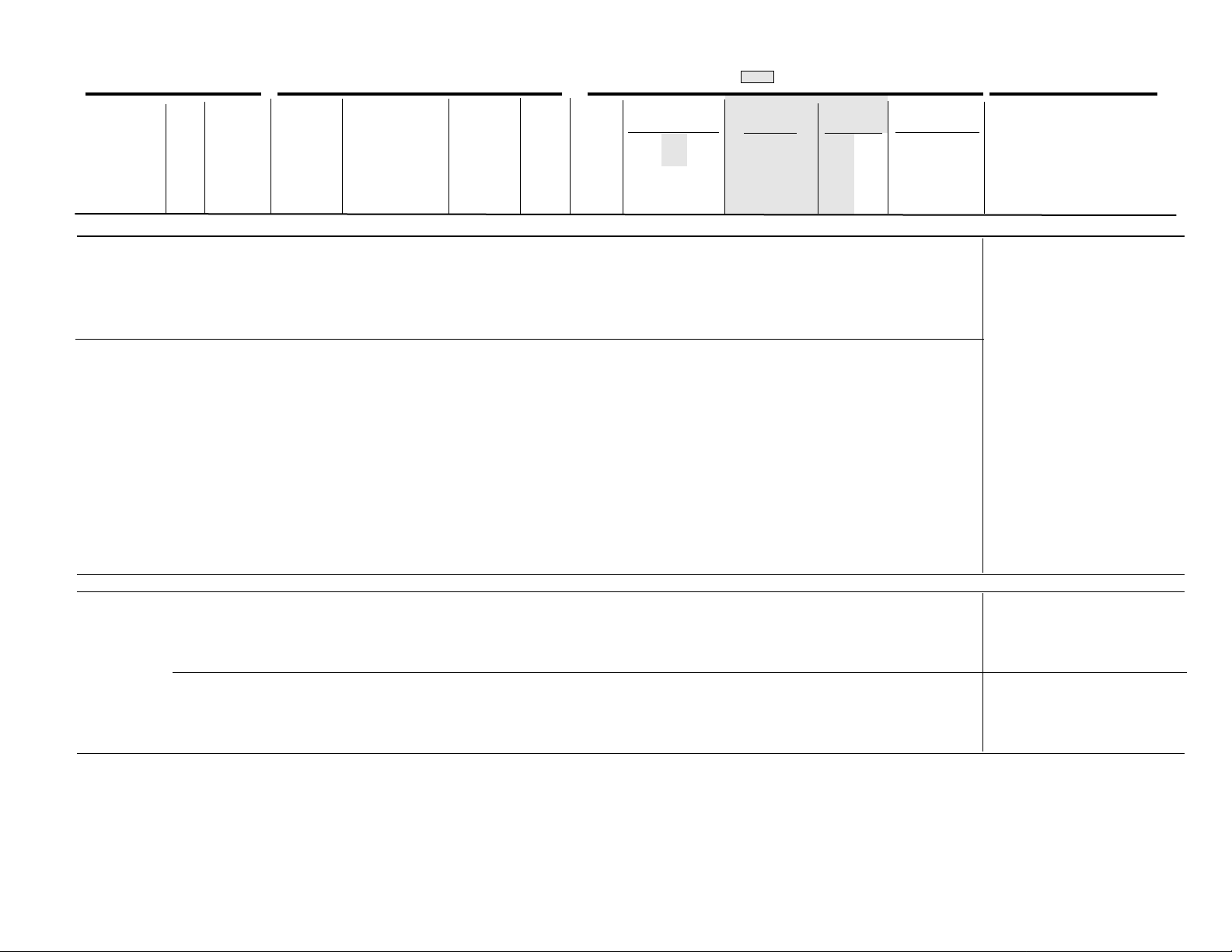
33
Motorola PowerPC 7XX Family
PowerPC All IA Only, Anly Prb √√√ √ E9586A #001 8/10 2 2 2 √√ 22 √
E9586A #001-former product# E2498A
740 Custom Emul Soln √√√√√ E9486B #001 8/10 2 2 2
Inverse assembler on 1670X/1660X frames
Probing Emul Prb √ E5900B #070 supports code flow only mode which
Emul Mod √√ E5901B #070 provides inverse assembly from
Emul Migr √√ E5902A #070
address and status information
Emul Migr √√ E5902B #070 only. This mode requires a minimum
Emulation Only - All All Emul Prb √ E5900B #070 of 4 pods. Cache on trace reconstruction
740 Emul Mod √√ E5901B #070
makes use of processor branch trace
Emul Migr √√ E5902A #070 mode and reconstructs the full software
Emul Migr √√ E5902B #070 trace. This allows the processor to run full
speed, uninterrupted from internal flash or
cache with cache enabled. All PowerPC
7XX emulation products require a JTAG
port on the target. E5902A #070 is only
compatible with E5900A #070 or E5901A #070.
E5902B #070 is only compatible with E5900B
#070 or E5901B #070.
Product Literature: 5966-2867E
PowerPC 7XX Related Products A debugger is available from the following vendors: GHS, Microtec/Mentor, SDS, WindRiver. Contact the debugger company for detailed information.
PowerPC 740 66 255-BGA Adapter Ironwood LA-BGA-740-S-B-02
1
, 255-pin BGA
(soldered)
Electronics requires Agilent E9586A #001 and
LA-BGA-740-S-B-02 and
SF-BGA255A-B-01
66 255-BGA Adapter Ironwood LA-BGA-740-Z-B-02
1
, 255-pin BGA
(socketed)
Electronics requires Agilent E9586A #001 and
LA-BGA-740-Z-B-02 and
SF-BGA255A-B-01
16557
16550,16710/1/2
16715/6/7/8/9
1673
1672
1671
1670
Device
Manufacturer
or
Architecture
and Name
Max
Bus
Clk
MHz
Pin
Count,
Pkg
Type
Product
Type
3rd
Party
Vendor or
Agilent
Product
Number
Min #
Pods
for
IA /
Max #
Pods
16700A/B Series
with ...
Setup Assist
Emulation
Enhanced IA
State
Timing
1
Directly available from the 3rd party
vendor by this product #
2
Requires termination adapters
(P/N 01650-63203)
3
Available from Agilent through resale
program
4
Requires termination adapters
(P/N E5346A)
16603
16602
16601
16600
Device Coverage Product Information Logic Analyzer Support Notes:
16600A
Series
1670G Series
16550
16500C
with ...
16557
Products Discontinued
Agilent Technologies
Page 34

Motorola PowerPC 7XX Family continued
PowerPC All IA Only, Anly Prb √√√ √ E9586A #001 8/10 2 2 2 √√ 22 √
E9586A #001-former product# E2498A
750 Custom Emul Soln √√√√√ E9486B #001 8/10 2 2 2
Inverse assembler on 1670X/1660X frames
Probing Emul Prb √ E5900B #070
supports code flow only mode which
Emul Mod √√ E5901B #070 provides inverse assembly from
Emul Migr √√ E5902A #070 address and status information
Emul Migr √√ E5902B #070
only. This mode requires a minimum
Emulation Only - All All Emul Prb √ E5900B #070 of 4 pods. Cache on trace reconstruction
750 Emul Mod √√ E5901B #070 makes use of processor branch trace
Emul Migr √√ E5902A #070
mode and reconstructs the full software
Emul Migr √√ E5902B #070 trace. This allows the processor to run full
speed, uninterrupted from internal flash or
cache with cache enabled. All PowerPC
7XX emulation products require a JTAG port
on the target. E5902A #070 is only compatible
with E5900A #070 or E5901A #070. E5902B
#070 is only compatible with E5900B #070 or
E5901B #070.
Product Literature: 5966-2867E
PowerPC 7XX Related Products A debugger is available from the following vendors: GHS, Microtec/Mentor, SDS, WindRiver. Contact the debugger company for detailed information.
PowerPC 750 66 360-BGA Adapter Ironwood LA-BGA-750-S-B-02
1
, 360-pin BGA
(soldered) Electronics
requires Agilent E9586A #001 and
LA-BGA-750-S-B-02 and
SF-BGA360A-B-01
66 360-BGA Adapter Ironwood
LA-BGA-750-Z-B-02
1
,
360-pin BGA
(socketed) Electronics requires Agilent E9586A #001 and
LA-BGA-750-Z-B-02 and
SF-BGA360A-B-01
34
16557
16550,16710/1/2
16715/6/7/8/9
1673
1672
1671
1670
Device
Manufacturer
or
Architecture
and Name
Max
Bus
Clk
MHz
Pin
Count,
Pkg
Type
Product
Type
3rd
Party
Vendor or
Agilent
Product
Number
Min #
Pods
for
IA /
Max #
Pods
16700A/B Series
with ...
Setup Assist
Emulation
Enhanced IA
State
Timing
1
Directly available from the 3rd party
vendor by this product #
2
Requires termination adapters
(P/N 01650-63203)
3
Available from Agilent through resale
program
4
Requires termination adapters
(P/N E5346A)
16603
16602
16601
16600
Device Coverage Product Information Logic Analyzer Support Notes:
16600A
Series
1670G Series
16550
16500C
with ...
16557
Products Discontinued
Agilent Technologies
Page 35

Motorola PowerPC Family continued
MPC745/755 All IA Only, Anly Prb √√√ √ E9586A #001 8/10 2 2 2 √√
Inverse assembler on 1670X/1660X frames
(Goldfinger) Custom Emul Soln √√√√√ E9486B #001
supports code flow only mode which
Probing Emul Prb √ E5900B #070 provides inverse assembly from
Emul Mod √√ E5901B #070 address and status information
Emul Migr √√ E5902B #070
only. This mode requires a minimum
of 4 pods. Cache on trace reconstruction
makes use of processor branch trace
mode and reconstructs the full software
trace. This allows the processor to run full
speed, uninterrupted from internal flash or
cache with cache enabled. All PowerPC
7XX emulation products require a JTAG port
on the target.
Motorola PowerPC 7400 Family
MPC 7400 All IA Only, Anly Prb √√√ √ E9613B #001 8/10 2 2 2 √√ Cache on trace reconstruction makes
(Max) Custom Emul Soln √√√√√ E9513B #001 use of processor branch trace mode
Probing Emul Prb √ E5900B #110 and reconstructs the full software
Emul Mod √√ E5901B #110 trace. This allows the processor to run
Emul Migr √√ E5902B #110 full speed, uninterrupted from internal
flash or cache with cache enabled.
Motorola PowerPC 8XX Family
MPC801 All — I A √ Corelis 6/6 2 1 2 √√√ 12 √√
IA-MPC801, Qty: 3
4
Resale
Agilent: CRL-600783, Qty: 3
4
MPC823 All — I A √√ Corelis 6/6 2 1 2 √√√ 12 √√
IA-MPC823, Qty: 3
4
Resale Agilent: CRL-60071
3
, Qty: 3
4
66 BGA Anly Prb √√√ Corelis 6/11 2 1 2 √√√ 12 √√ PI-MPC823, Qty: 3
4
Resale
Agilent: CRL-600723, Qty: 3
4
MPC850 All — I A √√ Corelis 6/6 2 1 2 √√√ 12 √√ IA-MPC850, Qty: 3
4
Resale Agilent: CRL-60071
3
, Qty: 3
4
66 BGA Anly Prb √√√ Corelis 6/11 2 1 2 √√√ 12 √√ PI-MPC850, Qty: 3
4
Resale Agilent: CRL-60072
3
, Qty: 3
4
35
16557
16550,16710/1/2
16715/6/7/8/9
1673
1672
1671
1670
Device
Manufacturer
or
Architecture
and Name
Max
Bus
Clk
MHz
Pin
Count,
Pkg
Type
Product
Type
3rd
Party
Vendor or
Agilent
Product
Number
Min #
Pods
for
IA /
Max #
Pods
16700A/B Series
with ...
Setup Assist
Emulation
Enhanced IA
State
Timing
1
Directly available from the 3rd party
vendor by this product #
2
Requires termination adapters
(P/N 01650-63203)
3
Available from Agilent through resale
program
4
Requires termination adapters
(P/N E5346A)
16603
16602
16601
16600
Device Coverage Product Information Logic Analyzer Support Notes:
16600A
Series
1670G Series
16550
16500C
with ...
16557
Products Discontinued
Agilent Technologies
Page 36

Motorola PowerPC 8XX Family continued
MPC855, IA Only, Anly Prb √√√ √ E9584B #001 6/12 2 1 2 √√√ 12 √√ E9584B #002-former product# E2476B
860 DP/P/T 50 Custom Emul Soln √√√√√ E9484B #001 6/12 2 1 2
Inverse assembler supports trace
Probing Emul Prb √ E5900B #080
reconstruction. Trace reconstruction
Emul Mod √√ E5901B #080 makes use of branch show cycles and
Emul Migr √√ E5902A #080 reconstructs the full software trace.
Emul Migr √√ E5902B #080
This allows the processor to run with
357-BGA Anly Prb √√√ √ E9584B #002 6/12 2 1 2 √√√ 12 √√ cache enabled. Emulation products can
Emul Soln √√√√√ E9484B #002 6/12 2 1 2 connect directly to BDMport via the
Emul Prb √ E5900B #080
MPC860 analysis probe, otherwise
Emul Mod √√ E5901B #080
requires BDM port on the target.
Emul Migr √√ E5902A #080 Product Literature: 5966-2866E
Emul Migr √√ E5902B #080
Emulation Only - All All Emul Prb √ E5900B #080 Former product #: E3497A
801,821,823,850, Emul Mod √√ E5901B #080 Emulation module or probe can
855, 860 Families Emul Migr √√ E5902A #080
connect directly to BDM port via
Emul Migr √√ E5902B #080 the analysis probe, otherwise
requires BDM port on the target.
Product Literature: 5966-2866E
PowerPC 8XX Related Products Debuggers are available from the following vendors: GHS, Microtec/Mentor, SDS, WindRiver. Contact the debugger company for detailed information.
36
16557
16550,16710/1/2
16715/6/7/8/9
1673
1672
1671
1670
Device
Manufacturer
or
Architecture
and Name
Max
Bus
Clk
MHz
Pin
Count,
Pkg
Type
Product
Type
3rd
Party
Vendor or
Agilent
Product
Number
Min #
Pods
for
IA /
Max #
Pods
16700A/B Series
with ...
Setup Assist
Emulation
Enhanced IA
State
Timing
1
Directly available from the 3rd party
vendor by this product #
2
Requires termination adapters
(P/N 01650-63203)
3
Available from Agilent through resale
program
4
Requires termination adapters
(P/N E5346A)
16603
16602
16601
16600
Device Coverage Product Information Logic Analyzer Support Notes:
16600A
Series
1670G Series
16550
16500C
with ...
16557
Products Discontinued
Agilent Technologies
Page 37

37
Motorola PowerPC 82XX Family
MPC8240 100 IA Only, Anly Prb √√√ √ E9611A #001 8/14 2 2 2 √√
Inverse assembler also supports code-flow
(
Kahlua) Custom Emul Soln √√√√√ E9511B #001 8/14 2 2 2 only mode which provides inverse assembly
Probing Emul Prb √ E5900B #100 from address and status information only.
Emul Mod √√ E5901B #100
This mode requires a minimum of 4 pods. Cache
Emul Migr √√ E5902A #100
on trace reconstruction makes use of
Emul Migr √√ E5902B #100 processor branch trace mode and reconstructs
352-BGA Anly Prb √√√ √ E9611A #002 8/14 2 2 2 √√ the full software trace. This allows the
Emul Soln √√√√√ E9511B #002 8/14 2 2 2
processor to run full speed, uninterrupted from
Emul Prb √ E5900B #100 internal flash or cache with cache enabled. PCI
Emul Mod √√ E5901B #100 support available from FuturePlus Systems
Emul Migr √√ E5902A #100 Corporation. Custom probing application
Emul Migr √√ E5902B #100
note for IA only analysis: 5968-4263E
E5902A #100 is only compatible with E5900A
#100 or E5901A #100. E5902B #100 is only
compatible with E5900B #100 or E5901B #100.
Product Literature: 5968-1981E
MPC8260 66 IA Only, Anly Prb √√√ √ E9603A #001 8/22 2 2 2 √√ Cache on trace reconstruction makes use of
PowerQUICC II Custom Emul Soln √√√√√ E9503B #001 8/22 2 2 2
processor branch trace mode and reconstructs
(Voyager) Probing Emul Prb √ E5900B #100 the full software trace. This allows the
Emul Mod √√ E5901B #100 processor to run full speed, uninterrupted
Emul Migr √√ E5902A #100 from internal flash or cache with cache
Emul Migr √√ E5902B #100 enabled. PCI support available from
480-BGA Anly Prb √√√ √ E9603A #002 8/22 2 2 2 √√
FuturePlus Systems Corp. E5902A #100 is only
Emul Soln √√√√√ E9503B #002 8/22 2 2 2 compatible with E5900A #100 or E5901A #100.
Emul Prb √ E5900B #100 E5902B #100 is only compatible with
Emul Mod √√ E5901B #100
E5900B #100 or E5901B #100.
Emul Migr √√ E5902A #100 Product Literature: 5968-1981E
Emul Migr √√ E5902B #100
PowerPC 82XX Related Products Debuggers are available from the following vendors: GHS, Microtec/Mentor, SDS, WindRiver. Contact the debugger company for detailed information.
16557
16550,16710/1/2
16715/6/7/8/9
1673
1672
1671
1670
Device
Manufacturer
or
Architecture
and Name
Max
Bus
Clk
MHz
Pin
Count,
Pkg
Type
Product
Type
3rd
Party
Vendor or
Agilent
Product
Number
Min #
Pods
for
IA /
Max #
Pods
16700A/B Series
with ...
Setup Assist
Emulation
Enhanced IA
State
Timing
1
Directly available from the 3rd party
vendor by this product #
2
Requires termination adapters
(P/N 01650-63203)
3
Available from Agilent through resale
program
4
Requires termination adapters
(P/N E5346A)
16603
16602
16601
16600
Device Coverage Product Information Logic Analyzer Support Notes:
16600A
Series
1670G Series
16550
16500C
with ...
16557
Products Discontinued
Agilent Technologies
Page 38

Motorola 68K
68000/10 12.5 DIP Anly Prb √√ ET 3/4 1 1 1 √√√√ 11 √√√
HP-68000/10-DIP-PAS
1
, Qty:3
2
SDIP Anly Prb √√ ET 3/4 1 1 1 √√√√ 11 √√√
HP-68000/10-SDIP-PAS
1
, Qty:3
2
PLCC Anly Prb √√ ET 3/4 1 1 1 √√√√ 11 √√√ HP-68000/10-PLCC-PAS
1
, Qty:3
2
PGA Anly Prb √√ ET 3/4 1 1 1 √√√√ 11 √√√ HP-68000/10-PGA2-PAS
1
, Qty:3
2
68000/HC000 16.7 PGA Anly Prb √√ √ E2447AA 3/7 1 1 1 √√√√ 11 √√√
Termination adapters optional
68HC000/001 12.5 PGA Anly Prb √√ ET 3/4 1 1 1 √√√√ 11 √√√ HP-PGA7-QF03-T/S
1
, Qty:3
2
PLCC Anly Prb √√ ET 3/4 1 1 1 √√√√ 11 √√√
HP-68HC000/01-PLCC-PAS
1
,Qty:3
2
68EC000 16.7 PLCC Anly Prb √√ √ E2447AB 3/7 1 1 1 √√√√ 11 √√√
Termination adapters optional
68EC000 8 PLCC Anly Prb √√ ET 3/4 1 1 1 √√√√ 11 √√√
HP-68EC000-PLCC-PAS-AC
1
, Qty:3
2
68008 12.5 DIP Anly Prb √√ ET 3/4 1 1 1 √√√√ 11 √√√ HP-68008-DIP-PAS
1
, Qty:3
2
68020 33 PGA Anly Prb √√√ √ E2426A 5/6 2 1 2 √√√ 12 √√ 132-pin soldered PQFP requires
PQFP Adapter #1CC E2426A and #1CC.
68020 33 PQFP Anly Prb √√ ET 5/6 2 1 2 √√√ 12 √√ HP-68020-PQFP-PAS-AC
1
, Qty:5
2
68EC020 33 PGA Anly Prb √√√ √ E2426B 5/6 2 1 2 √√√ 12 √√ 100-pin soldered PQFP requires
PQFP Adapter #1CC E2426B and #1CC.
68030 50 PGA Anly Prb √√ √ E2406A 5/5 2 1 2 √√√ 12 √√ 132-pin soldered PQFP requires
PQFP Adapter #1CC E2406A and #1CC
68030 33 PQFP Anly Prb √√ ET 5/6 2 1 2 √√√ 12 √√ HP-68030-PQFP-PAS-AC-2
1
, Qty:5
2
68EC030 50 PGA Anly Prb √√ √ E2406A 5/5 2 1 2 √√√ 12 √√
68060/68040 50 PGA Anly Prb √√ √ E2459A 6/8 2 1 2 √√√ 12 √√
38
16557
16550,16710/1/2
16715/6/7/8/9
1673
1672
1671
1670
Device
Manufacturer
or
Architecture
and Name
Max
Bus
Clk
MHz
Pin
Count,
Pkg
Type
Product
Type
3rd
Party
Vendor or
Agilent
Product
Number
Min #
Pods
for
IA /
Max #
Pods
16700A/B Series
with ...
Setup Assist
Emulation
Enhanced IA
State
Timing
1
Directly available from the 3rd party
vendor by this product #
2
Requires termination adapters
(P/N 01650-63203)
3
Available from Agilent through resale
program
4
Requires termination adapters
(P/N E5346A)
16603
16602
16601
16600
Device Coverage Product Information Logic Analyzer Support Notes:
16600A
Series
1670G Series
16550
16500C
with ...
16557
Products Discontinued
Agilent Technologies
Page 39

39
Motorola CPU32 Family
68331/32/34/35 25 132-PQFP Anly Prb √√√ √ E9589A #002 4/12 1 1 1 √√√√ 11 √√√
E9589A #002- former product # E8115A
Emul Soln √√√√√ E9489A #002 4/12 1 1 1 √√√√
E9589A #003-former product# E8116A
Emul Prb √ E5900A #030 E5900A #030-former product# E3458A
Emul Mod √√ E5901A #030 Analysis probe requires emulation
Emul Migr √√ E5902A #030 module or probe to configure for
68331/32 25 144-TQFP Anly Prb √√√ √ E9589A #003 4/12 1 1 1 √√√√ 11 √√√ address reconstruction. Emulation
Emul Soln √√√√√ E9489A #003 4/12 1 1 1 √√√√ products can connect directly to BDM
Emul Prb √ E5900A #030 port via the analysis probe otherwise
Emul Mod √√ E5901A #030 requires BDM on the target.
Emul Migr √√ E5902A #030 Product Literature: 5966-3368E
Emulation Only - All All Emul Prb √ E5900A #030
68331/CK331, Emul Mod √√ E5901A #030
68332/68334, Emul Migr √√ E5902A #030
68335, LK332,
68331/32/34/35 Related Products Debuggers are available from the following vendors: GHS, Microtec/Mentor, SDS. Contact the debugger company for detailed information.
68336/76 25 160-PQFP Anly Prb √√√ √ E9596A #002 4/12 1 1 1 √√√√ 11 √√√ E9596A #002- former product# E8118A
Emul Soln √√√√√ E9496A #002 4/12 1 1 1 √√√√ E5900A #030- former product# E3458A
Emul Prb √ E5900A #030 Analysis probe requires emulation
Emul Mod √√ E5901A #030 probe or module to configure for
Emul Migr √√ E5902A #030 address reconstruction. Emulation
Emulation Only - Emul Prb √ E5900A #030 products can connect directly to BDM
68336,68376 Emul Mod √√ E5901A #030 port via the analysis probe, otherwise
Emul Migr √√ E5902A #030 requires BDM port on the target.
Product Literature: 5966-3368E
68336/76 Related Products Debuggers are available from the following vendors: GHS, Microtec/Mentor, SDS. Contact the debugger company for detailed information.
16557
16550,16710/1/2
16715/6/7/8/9
1673
1672
1671
1670
Device
Manufacturer
or
Architecture
and Name
Max
Bus
Clk
MHz
Pin
Count,
Pkg
Type
Product
Type
3rd
Party
Vendor or
Agilent
Product
Number
Min #
Pods
for
IA /
Max #
Pods
16700A/B Series
with ...
Setup Assist
Emulation
Enhanced IA
State
Timing
1
Directly available from the 3rd party
vendor by this product #
2
Requires termination adapters
(P/N 01650-63203)
3
Available from Agilent through resale
program
4
Requires termination adapters
(P/N E5346A)
16603
16602
16601
16600
Device Coverage Product Information Logic Analyzer Support Notes:
16600A
Series
1670G Series
16550
16500C
with ...
16557
Products Discontinued
Agilent Technologies
Page 40

40
Motorola CPU32 Family continued
68360, 68EN360, 33 241-PGA Anly Prb √√√ √ E9590A #002 6/12 2 1 2 √√√ 12 √√
E9590A #002-former product # E2448B
68MH360 Emul Soln √√√√√ E9490A #002 6/12 2 1 2 √√√
E9590A #003-former product # E8123A
Emul Prb √ E5900A #030 E5900A #030-former product # E3458A
Emul Mod √√ E5901A #030 Analysis probe requires emulation
Emul Migr √√ E5902A #030 probe or module to configure for
240-PQFP Anly Prb √√√ √ E9590A #003 6/12 2 1 2 √√√ 12 √√ address reconstruction. Emulation
Emul Soln √√√√√ E9490A #003 6/12 2 1 2 √√√ products can connect directly to
Emul Prb √ E5900A #030 BDM port via the analysis probe,
Emul Mod √√ E5901A #030 otherwise requires BDM port on
Emul Migr √√ E5902A #030
the target.
Emulation Only - All All Emul Prb √ E5900A #030
Product Literature: 5966-3368E
68360, 68EN360, Emul Mod √√ E5901A #030
68MH360 Emul Migr √√ E5902A #030
68360 Related Products Debuggers are available from the following vendors: GHS, Microtec/Mentor, SDS. Contact the debugger company for detailed information.
16557
16550,16710/1/2
16715/6/7/8/9
1673
1672
1671
1670
Device
Manufacturer
or
Architecture
and Name
Max
Bus
Clk
MHz
Pin
Count,
Pkg
Type
Product
Type
3rd
Party
Vendor or
Agilent
Product
Number
Min #
Pods
for
IA /
Max #
Pods
16700A/B Series
with ...
Setup Assist
Emulation
Enhanced IA
State
Timing
1
Directly available from the 3rd party
vendor by this product #
2
Requires termination adapters
(P/N 01650-63203)
3
Available from Agilent through resale
program
4
Requires termination adapters
(P/N E5346A)
16603
16602
16601
16600
Device Coverage Product Information Logic Analyzer Support Notes:
16600A
Series
1670G Series
16550
16500C
with ...
16557
Products Discontinued
Agilent Technologies
Page 41

Motorola CPU32 Family continued
Emulation Only - Emul Prb √ E5900A #030
E5900A #030-former product # E3458A
68330,68F333, 68CK338, Emul Mod √√ E5901A #030
Emulation products can connect
68340,68341, 68349 Emul Migr √√ E5902A #030
directly to BDM port via the analysis
probe, otherwise requires BDM port
on the target.
Product Literature: 5966-3368E
68330/33/38,68340/41/49 Related products Debuggers are available from the following vendors: GHS, Microtec/Mentor, SDS. Contact the debugger company for detailed information.
68340 All PGA Anly Prb √√ Corelis 3/7 1 1 1 √√√√ 11 √√√ PI-68340-P
1
,Qty:3
2
Resale Agilent: CRL-60052
3
,Qty:3
2
68340 20 PQFP Anly Prb √√ ET 4/7 1 1 1 √√√√ 11 √√√ HP-68340-QFP-PAS-AC
1
, Qty:4
2
Motorola Coldfire
CF5202, 100-TQFP Anly Prb √√ ALD 6/6 2 1 2 √√√ 12 √√ ALD-5202
1
CF5203 Resale Agilent: ALO-60015
3
Motorola 6830X
68302 All PGA Anly Prb √√ Corelis 3/6 1 1 1 √√√√ 11 √√√ PI-68302
1
,Qty:3
2
Resale Agilent: CRL-60049
3
,Qty:3
2
PQFP Anly Prb √√ Corelis 3/6 1 1 1 √√√√ 11 √√√ PI-68302-Q
1
,Qty:3
2
Resale
Agilent: CRL-60050
3
,Qty:3
2
68EN302 20 TQFP Anly Prb √√ Corelis 3/7 1 1 1 √√√√ 11 √√√ PI-68EN302
1
,Qty:3
2
Resale Agilent: CRL-60060
3
,Qty:3
2
68LC302 25 PGA Anly Prb √√ Corelis 3/6 1 1 1 √√√√ 11 √√√
PI-68LC302-P
1
,Qty:3
2
Resale Agilent: CRL-60065
3
,Qty:3
2
TQFP Anly Prb √√ Corelis 3/6 1 1 1 √√√√ 11 √√√ PI-68LC302-T
1
,Qty:3
2
Resale Agilent: CRL-60066
3
,Qty:3
2
41
16557
16550,16710/1/2
16715/6/7/8/9
1673
1672
1671
1670
Device
Manufacturer
or
Architecture
and Name
Max
Bus
Clk
MHz
Pin
Count,
Pkg
Type
Product
Type
3rd
Party
Vendor or
Agilent
Product
Number
Min #
Pods
for
IA /
Max #
Pods
16700A/B Series
with ...
Setup Assist
Emulation
Enhanced IA
State
Timing
1
Directly available from the 3rd party
vendor by this product #
2
Requires termination adapters
(P/N 01650-63203)
3
Available from Agilent through resale
program
4
Requires termination adapters
(P/N E5346A)
16603
16602
16601
16600
Device Coverage Product Information Logic Analyzer Support Notes:
16600A
Series
1670G Series
16550
16500C
with ...
16557
Products Discontinued
Agilent Technologies
Page 42
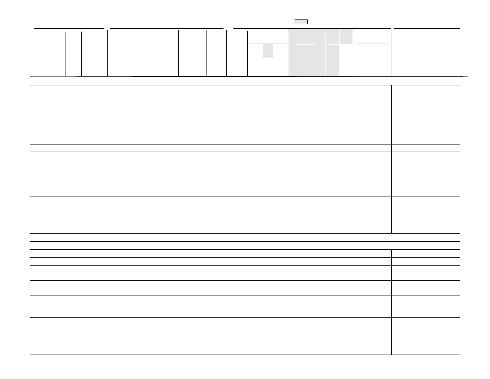
42
Motorola M-Core Family
DFP99, EIM All IAOnly Anly Prb √√√ Corelis 4/4 1 1 1 √√√√ 11 √√√
IA-MCORE-2
1
Interface Custom Resale
Agilent: CRL-60089
3
MMC2001, Probing
MMC2003,
MMC2499
Redcap 1, All IAOnly, Anly Prb √√√ Corelis 4/4 1 1 1 √√√√ 11 √√√
IA-MCORE-1
1
Redcap 2, Custom Resale
Agilent: CRL-60088
3
Wally Probing
Whitecap PGA Anly Prb √√√ Corelis 4/4 1 1 1 √√√√ 11 √√√ PI-Whitecap
Whitecap PGA Anly Prb √√√ Corelis 4/4 1 1 1 √√√√ 11 √√√
EPI-Whitecap
Aruba, 40 IA Only Anly Prb √√√ √ E9612A #001 4/6 1 1 1 √√√√ Custom probing application
Cayman Custom Emul Soln √√√√√ E9512A #001 4/6 1 1 1 √√√√
note for IA only analysis:
Probing Emul Prb √ E5900A #090
5968-2503E
Emul Mod √√ E5901A #090
Product Literature 5968-1982E
Emul Migr √√ E5902A #090
Emulation Only - All All Emul Prb √ E5900A #090
Aruba, Cayman, Emul Mod √√ E5901A #090
MMC2001/3, Emul Migr √√ E5902A #090
M-Core M210
Bondout
M-Core Related Products A debugger is available from the following vendor: SDS, GHS. Contact the debugger company for detailed information.
Motorola DSPs
56000/01 All — I A √ Factory 3/- 1 1 1 √√√√ 11 √√√
56116/156/166 All — I A √ Corelis 5/5 2 1 2 √√√ 12 √√ IA-56116/156/166
1
,Qty:5
2
56303 80 TQFP Anly Prb √√ Corelis 4/7 1 1 1 √√√√ 11 √√√ PI-56303
1
,Qty:4
2
Resale Agilent: CRL-60063
3
,Qty:4
2
56309 80 TQFP Anly Prb √√ Corelis 4/7 1 1 1 √√√√ 11 √√√ PI-56303
1
,Qty:4
2
Resale Agilent: CRL-60063
3
,Qty:4
2
56651/2/3/4 All IA Only, Anly Prb √√ Corelis 4/4 1 1 1 √√√√ 11 √√√ IA-MCORE-1
1
Custom Resale Agilent: CRL-60088
3
Probing
56690 All IA Only, Anly Prb √√√ Corelis 4/4 1 1 1 √√√√ 11 √√√ IA-MCORE-2
1
Custom Resale Agilent: CRL-60089
3
Probing
56L811 All TQFP Anly Prb √√ Corelis 4/5 1 1 1 √√√√ 11 √√√ PI-56L811
1
,Qty:4
2
Resale Agilent: CRL-60062
3
,Qty:4
2
16557
16550,16710/1/2
16715/6/7/8/9
1673
1672
1671
1670
Device
Manufacturer
or
Architecture
and Name
Max
Bus
Clk
MHz
Pin
Count,
Pkg
Type
Product
Type
3rd
Party
Vendor or
Agilent
Product
Number
Min #
Pods
for
IA /
Max #
Pods
16700A/B Series
with ...
Setup Assist
Emulation
Enhanced IA
State
Timing
1
Directly available from the 3rd party
vendor by this product #
2
Requires termination adapters
(P/N 01650-63203)
3
Available from Agilent through resale
program
4
Requires termination adapters
(P/N E5346A)
16603
16602
16601
16600
Device Coverage Product Information Logic Analyzer Support Notes:
16600A
Series
1670G Series
16550
16500C
with ...
16557
Products Discontinued
Agilent Technologies
Page 43

43
Motorola 68HCXX
68HC11 8.4 48-DIP Anly Prb √√ 10315G 3/4 1 1 1 √√√√ 11 √√√
68HC11 8.4 32-PLCC Anly Prb √√ 10315H 3/4 1 1 1 √√√√ 11 √√√
68HC11F1 8.4 PLCC Anly Prb √√ ET 3/4 1 1 1 √√√√ 11 √√√
HP-68HC11F1-PCC1-PAS
1
, Qty:3
2
68HC11KA2 PLCC Anly Prb √√ ET 3/4 1 1 1 √√√√ 11 √√√
HP-68HC11KA2-PLCC-PAS
1
, Qty:3
2
68HC11K4 8 PQFP Anly Prb √√ ET 2/5 1 1 1 √√√√ 11 √√√√HP-68HC11K4-QF14-PAS-AC
1
, Qty:2
2
68HC12B32 PQFP Anly Prb √√ ET 3/4 1 1 1 √√√√ 11 √√√
HP-68HC12B32-Q14
1
, Qty:3
2
Motorola 680X
6800/6802 2 DIP Anly Prb √ ET 2/3 1 1 1 √√√√ 11 √√√√HP-6800/2-DIP40-PAS
1
, Qty:2
2
6803 All — I A √ Factory 2/2 1
14680500 All — I A √ Factory 2/2 1
6809 2 DIP Anly Prb √ ET 2/3 1 1 1 √√√√ 11 √√√√
HP-6809-DIP40-PAS
1
, Qty:2
2
Motorola 88K
88100 35 PGA Anly Prb √√ Corelis 5/10 2 1 2 √√√ 12 √√ PI-88100
1
, Qty:5
2
88200 35 PGA Anly Prb √√ Corelis 5/10 2 1 2 √√√ 12 √√ PI-88200
1
, Qty:5
2
88110 50 PGA Anly Prb √√ Corelis 7/9 2 2 2 √√ 22 √ PI-88110
1
, Qty:7
2
16557
16550,16710/1/2
16715/6/7/8/9
1673
1672
1671
1670
Device
Manufacturer
or
Architecture
and Name
Max
Bus
Clk
MHz
Pin
Count,
Pkg
Type
Product
Type
3rd
Party
Vendor or
Agilent
Product
Number
Min #
Pods
for
IA /
Max #
Pods
16700A/B Series
with ...
Setup Assist
Emulation
Enhanced IA
State
Timing
1
Directly available from the 3rd party
vendor by this product #
2
Requires termination adapters
(P/N 01650-63203)
3
Available from Agilent through resale
program
4
Requires termination adapters
(P/N E5346A)
16603
16602
16601
16600
Device Coverage Product Information Logic Analyzer Support Notes:
16600A
Series
1670G Series
16550
16500C
with ...
16557
Products Discontinued
Agilent Technologies
Page 44

National
NS32016 All — I A √ Factory 3/3 1
HPC16003/4/64 All — I A √ Factory 3/3 1
NEC
7810/11 All — I A √ Factory 3/3 1
V25 16 PLCC Anly Prb √√ ET 3/5 1 1 1 √√√√ 11 √√√
HP-V25-PLCC-PAS
1
, Qty:3
2
V830 50 LQFP Anly Prb Corelis 5/6 2 1 2 √√√ 12 √√
PI-V830
1
, Qty:5
2
Vr4100 All TQFP Anly Prb √√ Corelis 6/6 2 1 2 √√√ 12 √√ PI-VR4100
1
,Qty:6
2
Resale Agilent: CRL-60067
3
,Qty:6
2
Vr4111 80 — I A √√√ Corelis 6/6 2 1 2 √√√ 12 √√ IA-VR4111
1
, Qty:3
4
Resale
Agilent: CRL-600773, Qty:3
4
Vr4200 50 PQFP Anly Prb √√ Corelis 6/7 2 1 2 √√√ 12 √√ PI-VR4200
1
, Qty:6
2
Vr4300 All PQFP Anly Prb √√ Corelis 4/4 1 1 1 √√√√ 11 √√√ PI-Vr4300
1
, Qty:4
2
Resale
Agilent: CRL-60033
3
, Qty:4
2
Vr5000 All PGA Anly Prb √√ Corelis 6/9 2 1 2 √√√ 12 √√ PI-R5000
1
, Qty:6
2
VR5432 100 PQFP Anly Prb √√√ Corelis 6/8 2 1 2 √√√ 12 √√ PI-VR5432
1
, Qty:3
4
Resale
Agilent: CRL-600763, Qty:3
4
VR5464 100 BGA Anly Prb √√√ Corelis 8/12 2 2 2 √√ 22 √ PI-VR5464
1
, Qty:3
4
Resale
Agilent: CRL-600753, Qty:3
4
44
16557
16550,16710/1/2
16715/6/7/8/9
1673
1672
1671
1670
Device
Manufacturer
or
Architecture
and Name
Max
Bus
Clk
MHz
Pin
Count,
Pkg
Type
Product
Type
3rd
Party
Vendor or
Agilent
Product
Number
Min #
Pods
for
IA /
Max #
Pods
16700A/B Series
with ...
Setup Assist
Emulation
Enhanced IA
State
Timing
1
Directly available from the 3rd party
vendor by this product #
2
Requires termination adapters
(P/N 01650-63203)
3
Available from Agilent through resale
program
4
Requires termination adapters
(P/N E5346A)
16603
16602
16601
16600
Device Coverage Product Information Logic Analyzer Support Notes:
16600A
Series
1670G Series
16550
16500C
with ...
16557
Products Discontinued
Agilent Technologies
Page 45
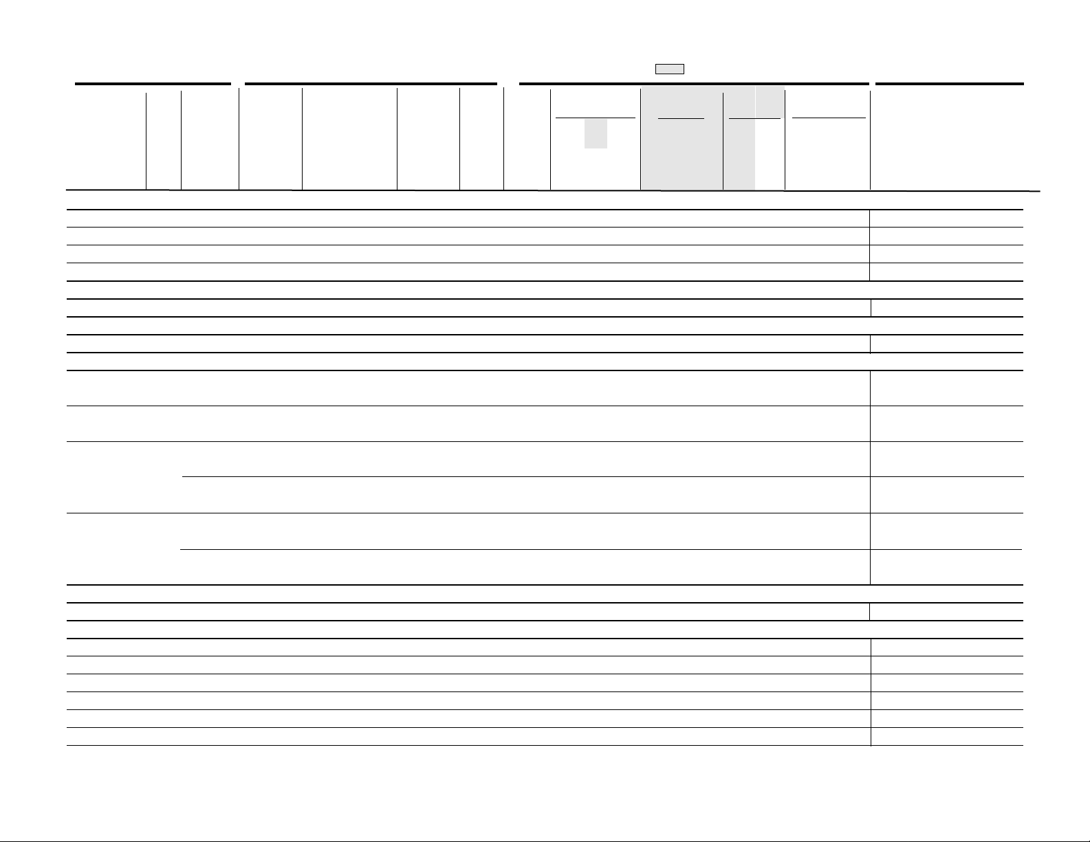
45
NKK
NR4645MQF All PQFP Anly Prb √√ Corelis 4/4 1 1 1 √√√√ 11 √√√
PI-NR4645MQF
1
, Qty:4
2
NR4650GQF All PQFP Anly Prb √√ Corelis 6/7 2 1 2 √√√ 12 √√ PI-NR4650GQF
1
, Qty:6
2
NR4650LQF All PQFP Anly Prb √√ Corelis 6/7 2 1 2 √√√ 12 √√
PI-NR4650LQF
1
, Qty:6
2
NR4700LMQ All PQFP Anly Prb √√ Corelis 6/7 2 1 2 √√√ 12 √√ PI-NR4700LMQ
1
,Qty:6
2
PACE
1750 40 PGA Anly Prb √ Lital 3/3 1 1 1 1 1 √√√
Performance
R4000/4400PC 50 PGA Anly Prb √√ Corelis 8/9 2 2 2 √√ 22 √
PI-R4000/4400
1
QED
RM5230/31 67 PQFP Anly Prb √√ Corelis 6/7 2 1 2 √√√ 12 √√ PI-5230
1
,Qty:6
2
Resale Agilent: CRL-60069
3
,Qty:6
2
RM5261 67 PQFP Anly Prb √√ Corelis 6/11 2 1 2 √√√ 12 √√
PI-5261
1
,Qty:6
2
Resale Agilent: CRL-60070
3
,Qty:6
2
RM5270/71 100 BGA Anly Prb √√√ Corelis 6/12 2 1 2 √√√ 12 √√ PI-RM5271
1
,Qty:3
4
Resale
Agilent: CRL-600743,Qty:3
4
IA Only Anly Prb √√√ Corelis 6/12 2 1 2 √√√ 12 √√ IA-RM5270/71
RM7000 100 BGA Anly Prb √√√ Corelis 6/12 2 1 2 √√√ 12 √√
PI-RM7000
1
,Qty:3
4
Resale Agilent: CRL-60073
3
,Qty:3
4
IA Only Anly Prb √√√ Corelis 6/12 2 1 2 √√√ 12 √√ IA-RM7000
1
Rockwell
6502 All — I A √ Factory 2/2 1
Siemens
R4000/4400PC 50 PGA Anly Prb √√ Corelis 8/9 2 2 2 √√ 22 √ PI-R4000/4400
1
80C165 PQFP Anly Prb √√ ET 3/7 1 1 1 √√√√ 11 √√√ HP-SABC165-QF06-PAS
1
, Qty:3
2
80C166 40 PQFP Anly Prb √√ ET 3/8 1 1 1 √√√√ 11 √√√ HP-80C166-QF06-PAS-AC
1
, Qty:3
2
80C167 — PQFP Anly Prb √√ ET 4/9 1 1 1 √√√√ 11 √√√ HP-SABC167-QF10-PAS, Qty:4
2
80C515 16 PLCC Anly Prb √√ ET 2/4 1 1 1 √√√√ 11 √√√√HP-80515/535-PLCC-PAS-AC
1
, Qty:2
2
80C517/537 PLCC Anly Prb √√ ET 2/4 1 1 1 √√√√ 11 √√√√HP-80C517/537-PLCC-PAS
1
, Qty:2
2
16557
16550,16710/1/2
16715/6/7/8/9
1673
1672
1671
1670
Device
Manufacturer
or
Architecture
and Name
Max
Bus
Clk
MHz
Pin
Count,
Pkg
Type
Product
Type
3rd
Party
Vendor or
Agilent
Product
Number
Min #
Pods
for
IA /
Max #
Pods
16700A/B Series
with ...
Setup Assist
Emulation
Enhanced IA
State
Timing
1
Directly available from the 3rd party
vendor by this product #
2
Requires termination adapters
(P/N 01650-63203)
3
Available from Agilent through resale
program
4
Requires termination adapters
(P/N E5346A)
16603
16602
16601
16600
Device Coverage Product Information Logic Analyzer Support Notes:
16600A
Series
1670G Series
16550
16500C
with ...
16557
Products Discontinued
Agilent Technologies
Page 46
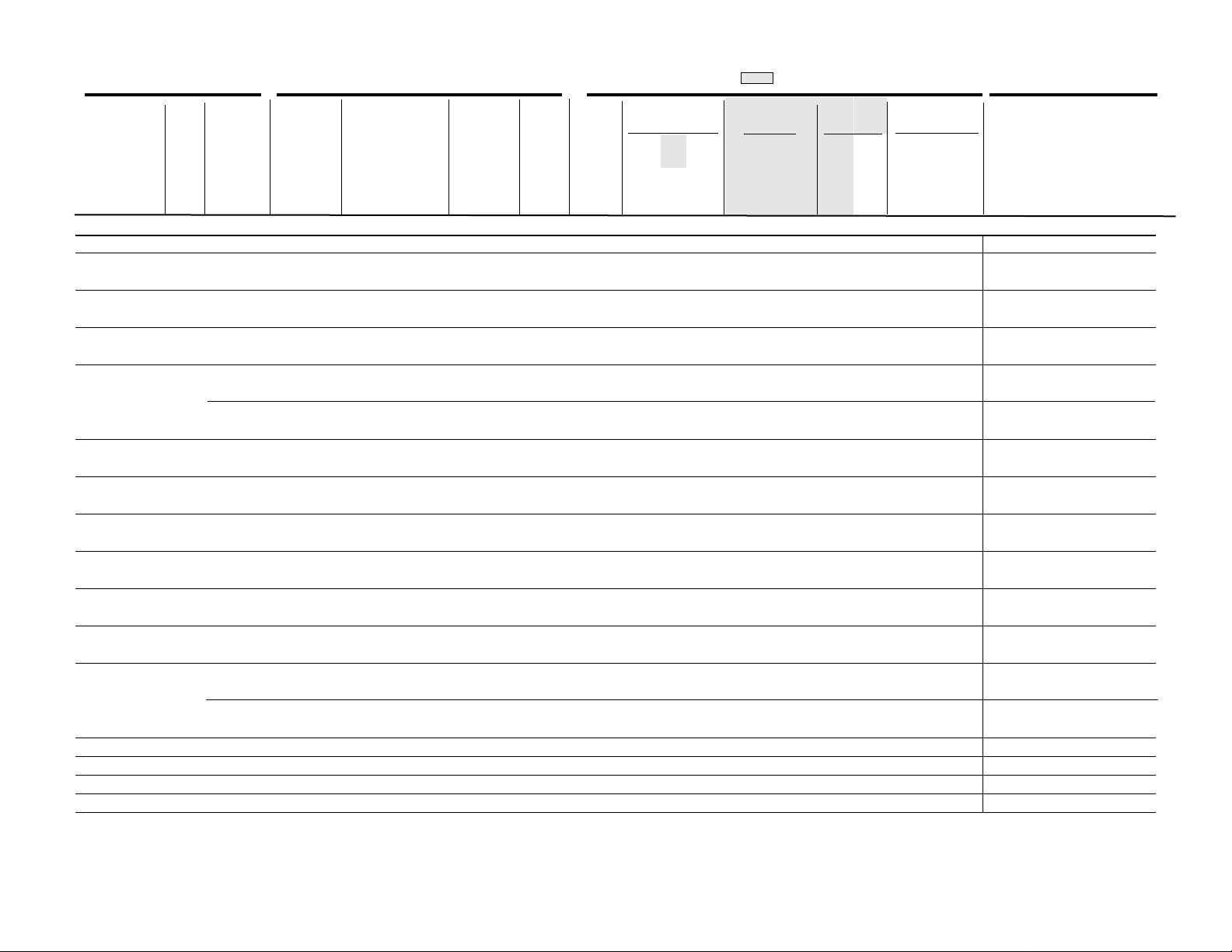
46
Texas Instruments
320C10/14 All — I A √ Factory 2/2 1
320C20/25 50 PGA Anly Prb √√ Corelis 3/3 1 1 1 √√√√ 11 √√√
PI-320C2X
1
,Qty:3
2
Resale Agilent: CRL-60044
3
,Qty:3
2
320C30 40 PGA Anly Prb √ Corelis 4/7 1 1 1 √√√√ 11 √√√
PI-320C30-P
1
Resale Agilent: CRL-60045
3
320C31 40 PQFP Anly Prb √ Corelis 4/7 1 1 1 √√√√ 11 √√√
PI-320C31-Q
1
Resale Agilent: CRL-60046
3
320C32 All PQFP Anly Prb √√ Corelis 6/6 2 1 2 √√√ 12 √√
PI-320C32-P
1
,Qty:6
2
Resale Agilent: CRL-60051
3
,Qty:6
2
TQFP Anly Prb √√ Corelis 6/6 2 1 2 √√√ 12 √√ PI-320C32T
1
,Qty:6
2
Resale Agilent: CRL-600423,Qty:6
2
320C40 All PGA Anly Prb √√ Corelis 5/16 2 1 2 √√√ 12 √√ PI-320C40
1
,Qty:5
2
Resale Agilent: CRL-60025
3
,Qty:5
2
320C50/51/53 28.5 PQFP Anly Prb √√ Corelis 3/6 1 1 1 √√√√ 11 √√√ PI-320C50/51/53
1
,Qty:3
2
Resale Agilent: CRL-60047
3
,Qty:3
2
320C52 All PQFP Anly Prb √√ Corelis 4/4 1 1 1 √√√√ 11 √√√ PI-320C52
1
,Qty:4
2
Resale Agilent: CRL-60043
3
,Qty:4
2
320C80 All PGA Anly Prb √ Corelis -/8 2 2 2 √√ 22 √ UI-320C80
1
,Qty:8
2
Resale Agilent: CRL-60068
3
,Qty:8
2
320C20X Family All — IA √√√ Corelis 3/3 1 1 1 √√√√ 11 √√√ IA-320C2XX
1
Resale
Agilent: CRL-60084
2
320C24X Family All — IA √√√ Corelis 3/3 1 1 1 √√√√ 11 √√√ IA-320C2XX
1
Resale Agilent: CRL-60084
4
320C542/48/49 All IA Only Anly Prb √√ Corelis 4/7 1 1 1 √√√√ 11 √√√ PI-320C542/548/549
TQFP Anly Prb √√ Corelis 4/7 1 1 1 √√√√ 11 √√√ PI-320C548
1
,Qty:4
2
Resale Agilent: CRL-60061
3
,Qty:4
2
34010 All — I A √ Factory 2/2 1
370C16 All — I A √ Corelis 6/6 2 1 2 √√√ 12 √√ IA-370C16
1
370C50 20 — I A √ Factory 2/2 1
470R1X All TQFP Anly Prb √√ Corelis 4/4 1 1 1 √√√√ 11 √√√ PI-R470
1
,Qty:4
2
16557
16550,16710/1/2
16715/6/7/8/9
1673
1672
1671
1670
Device
Manufacturer
or
Architecture
and Name
Max
Bus
Clk
MHz
Pin
Count,
Pkg
Type
Product
Type
3rd
Party
Vendor or
Agilent
Product
Number
Min #
Pods
for
IA /
Max #
Pods
16700A/B Series
with ...
Setup Assist
Emulation
Enhanced IA
State
Timing
1
Directly available from the 3rd party
vendor by this product #
2
Requires termination adapters
(P/N 01650-63203)
3
Available from Agilent through resale
program
4
Requires termination adapters
(P/N E5346A)
16603
16602
16601
16600
Device Coverage Product Information Logic Analyzer Support Notes:
16600A
Series
1670G Series
16550
16500C
with ...
16557
Products Discontinued
Agilent Technologies
Page 47
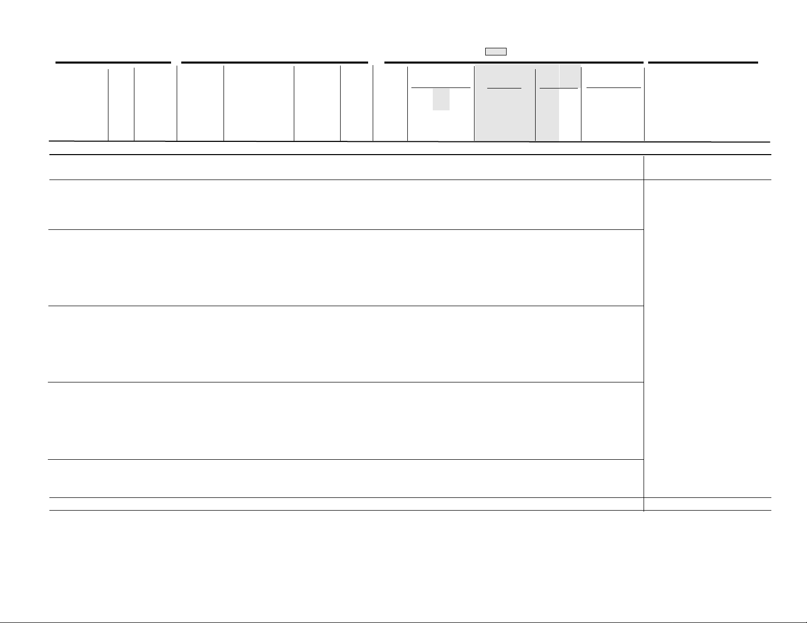
47
Toshiba
R3900 All PQFP Anly Prb √√ Corelis 6/7 2 1 2 √√√ 12 √√
PI-R39001,Qty:6
2
Resale Agilent:CRL-60034
3
,Qty:6
2
TMPR 1940 All All Emul Probe √ E5900A #800 Analysis probe requires B3759A #800 for
Emul Mod √√ E5901A #800
state analysis. For custom probing, B3759A #800
Emul Migr √√ E5902A #800
provides inverse assembly. E5903A #800 requires
Trce Prt Anly √ E5903A #800 B3759A #800. E5903A #800 requires either
TMPR3901 All 160-QFP Anly Prb √√ √ E9600A #002 6 1 2 √√√ emulation probe or emulation module.
Emul Soln √√ √√ E9500A #002 6 1 2 √√√
Emulation probe or module requires E5903A
Emul Prb √ E5900A #800 #800. The emulation products require a
Emul Mod √√ E5901A #800 double row 20 pin connector on target.
Emul Migr √√ E5902A #800 Refer to literature for specifications. Emulation
Trce Prt Anly √ E5903A #800
solution does not include B4620B Source
TMPR3903 All 208-QFP Anly Prb √√ √ E9601A #002 6 1 2 √√√ correlation tool set. Equivalent functionality is
Emul Soln √√ √√ E9501A #002 6 1 2 √√√ provided by B3759A #800. A debugger is also
Emul Prb √ E5900A #800
available from GHS. Product literature: 5968-2697E
Emul Mod √√ E5901A #800
Emul Migr √√ E5902A #800
Trce Prt Anly √ E5903A #800
TMPR3904 All 208-QFP Anly Prb √√ √ E9602A #002 6-8 1 2 √√√
Emul Soln √√ √√ E9502A #002 6-8 1 2 √√√
Emul Prb √ E5900A #800
Emul Mod √√ E5901A #800
Emul Migr √√ E5902A #800
Trce Prt Anly √ E5903A #800
TMPR3927 All All Emul Probe √ E5900A #810
Emul Migr √√ E5902A #810
Trce Prt Anly √ E5903A #810
R4000/4400PC 50 PGA Anly Prb √√ Corelis 8/9 2 2 2 √√ 22 √ PI-R4000/4400
1
16557
16550,16710/1/2
16715/6/7/8/9
1673
1672
1671
1670
Device
Manufacturer
or
Architecture
and Name
Max
Bus
Clk
MHz
Pin
Count,
Pkg
Type
Product
Type
3rd
Party
Vendor or
Agilent
Product
Number
Min #
Pods
for
IA /
Max #
Pods
16700A/B Series
with ...
Setup Assist
Emulation
Enhanced IA
State
Timing
1
Directly available from the 3rd party
vendor by this product #
2
Requires termination adapters
(P/N 01650-63203)
3
Available from Agilent through resale
program
4
Requires termination adapters
(P/N E5346A)
16603
16602
16601
16600
Device Coverage Product Information Logic Analyzer Support Notes:
16600A
Series
1670G Series
16550
16500C
with ...
16557
Products Discontinued
Agilent Technologies
Page 48

48
Xilinx LCA
XC4005/4006 75 156-PGA Anly Prb √ Corelis -/8 2 2 2 √√ 22 √ LXC-4000/PG156
1
,Qty:8
2
XC4008/4010 75 191-PGA Anly Prb √ Corelis -/8 2 2 2 √√ 22 √
LXC-4000/PG1911,Qty:8
2
Zilog
Z80 16 DIP Anly Prb √√ ET 2/3 1 1 1 √√√√ 11 √√√√
HP-Z80-DIP-PAS1, Qty:2
2
Z80 16 PLCC Anly Prb √√ ET 2/3 1 1 1 √√√√ 11 √√√√HP-Z80-PLCC-PAS
1
, Qty:2
2
Z180 16 PLCC Anly Prb √√ ET 2/4 1 1 1 √√√√ 11 √√√√HP-Z180-PLCC-PAS
1
, Qty:2
2
Z8001/8002 All — I A √ Factory 3/3 1
Standard Buses
Consider the B4601B Serial Analysis tool set for your serial bus measurements. The serial analysis tool works with the 16600A and 16700 series logic analysis systems. The tool converts acquired
serial bit streams to parallel format for easy viewing and analysis. It also allows you to process frame information to isolate the data you want to analyze. See the Application Software (pg. 15)
section of this document for more details.
AGP2X 133 N/A Anly Prb √ FuturePlus 4/4 1 1 1 √√√√ 11 √√√ FS2220
1
,Qty:2
4
Resale
Agilent: FSI-600223, Qty:2
4
AGP4X 266 N/A Anly Prb √ FuturePlus 12 3 FS2221
1
Resale
Agilent: FSI-60032
3
These cards must be
configured as a contiguous set.
APIC 33 N/A Anly Prb √√ √ E2467A 2-4 1 1 1 √√√√ 11 √√√√Product Literature: 5965-3000E
Compact PCI/Ext 66 N/A Anly Prb √√√ FuturePlus 4-7 1 1 1 √√√√ 11 √√√ FS3020
1
Refer to FuturePlus
specifications
Resale Agilent: FSI-60021
3
16557
16550,16710/1/2
16715/6/7/8/9
1673
1672
1671
1670
Device
Manufacturer
or
Architecture
and Name
Max
Bus
Clk
MHz
Pin
Count,
Pkg
Type
Product
Type
3rd
Party
Vendor or
Agilent
Product
Number
Min #
Pods
for
IA /
Max #
Pods
16700A/B Series
with ...
Setup Assist
Emulation
Enhanced IA
State
Timing
1
Directly available from the 3rd party
vendor by this product #
2
Requires termination adapters
(P/N 01650-63203)
3
Available from Agilent through resale
program
4
Requires termination adapters
(P/N E5346A)
16603
16602
16601
16600
Device Coverage Product Information Logic Analyzer Support Notes:
16600A
Series
1670G Series
16550
16500C
with ...
16557
Products Discontinued
Agilent Technologies
Page 49
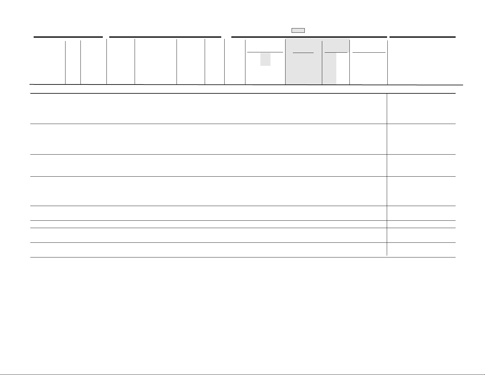
Standard Buses continued
Direct Rambus, 800 N/A Anly Prb √ FuturePlus FS2222
1
184 pin RIMM Resale Agilent: FSI-60033
3
Requires (1) 16517A, (3) 16518A, and
(1) 1670X Frame.
Direct Rambus, 400 N/A Anly Prb √ FuturePlus FS2224
1
Gen. Purp. Probe Resale
HP #: FSI-60035
3
Requires (1) 16517A, (3) 16518A, and
(1) 1670X Frame.
Fibre Channel 1062.5 N/A Anly Prb √ FuturePlus 4-8 1 1 1 √√√√ 11 √√√ FS4300
1
Refer to FuturePlus
specifications
Resale
Agilent: FSI-60031
3
I2C N/A Opt to ALD’s √√ ALD 2/2 1 1 1 √√√√ 11 √√√√
ALD-232 opt I2C1Requires
RS232c Anly
ordering ALD’s RS232c Analysis
Prb
Probe and the I2C option.
Resale
Agilent: ALO-60014
3
IBM ISA (AT) All N/A Anly Prb √√ Corelis 6/6 2 1 2 √√√ 12 √√
PI-ISA
1
Resale
Agilent: CRL-60029
3
IBM ISA (AT) N/A Anly Prb √√ Lital 5/5 2 1 2 1 2 √√
IEEE 488 (HPIB) N/A Anly Prb √√ ALD 1/2 1 1 1 √√√√ 11 √√√√ALD-488
1
Resale Agilent: ALO-60010
3
IEEE 1284 N/A Anly Prb √√ ALD 2/2 1 1 1 √√√√ 11 √√√√ALD-232
1
Resale Agilent: ALO-60008
3
16557
16550,16710/1/2
16715/6/7/8/9
1673
1672
1671
1670
Device
Manufacturer
or
Architecture
and Name
Max
Bus
Clk
MHz
Pin
Count,
Pkg
Type
Product
Type
3rd
Party
Vendor or
Agilent
Product
Number
Min #
Pods
for
IA /
Max #
Pods
16700A/B Series
with ...
Setup Assist
Emulation
Enhanced IA
State
Timing
1
Directly available from the 3rd party
vendor by this product #
2
Requires termination adapters
(P/N 01650-63203)
3
Available from Agilent through resale
program
4
Requires termination adapters
(P/N E5346A)
16603
16602
16601
16600
Device Coverage Product Information Logic Analyzer Support Notes:
16600A
Series
1670G Series
16550
16500C
with ...
16557
Products Discontinued
Agilent Technologies
49
Page 50

Standard Buses continued
JTAG 1149.1 All N/A Anly Prb √√ Corelis 1/1 1 1 1 √√√√ 11 √√√√BA-1149.1
1
Resale Agilent: CRL-60027
3
IEEE-1394 400 N/A Anly Prb √√ FuturePlus 4-6 1 1 1 √√√√ 11 √√√ FS4200
1
Refer to FuturePlus
specifications
Resale Agilent: FSI-60030
3
JTAG 1149.5 All N/A Anly Prb √√ Corelis 1/1 1 1 1 √√√√ 11 √√ √ √ BA-1149.5
1
PCI-64 Passive 66 N/A Anly Prb √√√ FuturePlus 4-6 1 1 1 √√√√ 11 √√√ FS2001
1
Refer to FuturePlus
specifications
Resale Agilent: FSI-60005
3
PCI/EXT-32 33 N/A Anly Prb √√√ FuturePlus 4/4 1 1 1 √√√√ 11 √√√ FS2000
1
Passive Resale
Agilent: FSI-60006
3
PCI/EXT-64 66 N/A Anly Prb √√√ FuturePlus 4-6 1 1 1 √√√√ 11 √√√ FS2005
1
, Qty:34Refer to FuturePlus
Passive,3.3 volts specifications
Resale
Agilent: FSI-60025
3
, Qty:3
4
PCI/EXT-64 66 N/A Anly Prb √√√ FuturePlus 4-6 1 1 1 √√√√ 11 √√√ FS2006
1
, Qty:34Refer to
Passive, 5 volts
FuturePlus specifications
Resale Agilent: FSI-60026
3
, Qty:3
4
PCI/EXT-64 33 N/A Anly Prb √√√ FuturePlus 4-11 1 1 1 √√√√ 11 √√√ FS2100
1
Refer to FuturePlus
Active,3.3 volts specifications
Resale Agilent: FSI-60016
3
PCI/EXT-64 66 N/A Anly Prb √√√ FuturePlus 4-10 1 1 1 √√√√ 11 √√√ FS2102
1
Refer to FuturePlus
Active, 3.3 volts specifications
Resale Agilent: FSI-60027
3
PCI/EXT-64 33 N/A Anly Prb √√√ FuturePlus 4-11 1 1 1 √√√√ 11 √√√ FS2101
1
Refer to FuturePlus
Active, 5 volts specifications
Resale Agilent: FSI-60017
3
PCI/EXT-64 66 N/A Anly Prb √√√ FuturePlus 4/10 1 1 1 √√√√ 11 √√√ FS2103
1
Refer to FuturePlus
Active, 5 volts specifications
Resale Agilent: FSI-60028
3
PCI Mezzanine 33 N/A Anly Prb √√√ FuturePlus 4/4 1 1 1 √√√√ 11 √√√ FS3010
1
(PMC) Resale Agilent: FSI-60010
3
PCI EIO 33 N/A Anly Prb √√√ FuturePlus 4/4 1 1 1 √√√√ 11 √√√ FS3030
1
Resale Agilent: FSI-60029
3
50
16557
16550,16710/1/2
16715/6/7/8/9
1673
1672
1671
1670
Device
Manufacturer
or
Architecture
and Name
Max
Bus
Clk
MHz
Pin
Count,
Pkg
Type
Product
Type
3rd
Party
Vendor or
Agilent
Product
Number
Min #
Pods
for
IA /
Max #
Pods
16700A/B Series
with ...
Setup Assist
Emulation
Enhanced IA
State
Timing
1
Directly available from the 3rd party
vendor by this product #
2
Requires termination adapters
(P/N 01650-63203)
3
Available from Agilent through resale
program
4
Requires termination adapters
(P/N E5346A)
16603
16602
16601
16600
Device Coverage Product Information Logic Analyzer Support Notes:
16600A
Series
1670G Series
16550
16500C
with ...
16557
Products Discontinued
Agilent Technologies
Page 51

51
Standard Buses continued
Cardbus 33 N/A Anly Prb √√√ FuturePlus 4/4 1 1 1 √√√√ 11 √√√ FS2004
1
Resale Agilent: FSI-60018
3
PCI-32/Extender 66 N/A Anly Prb √√ Corelis 4/4 1 1 1 √√√√ 11 √√√
PI-PCI32
1
Resale Agilent: CRL-60030
3
PCI-32E/ 66 N/A Anly Prb √√ Corelis 6/6 2 1 2 √√√ 12 √√
PI-PCI32/E
1
Hot-Swap Extender
PCI-64/Extender 66 N/A Anly Prb √√ Corelis 6/6 2 1 2 √√√ 12 √√
PI-PCI64
1
Resale Agilent: CRL-60031
3
PCMCIA N/A Anly Prb √ Mobile -/4 1 1 1 √√√√ 11 √√√
PCI-X/EXT-64 133 N/A Anly Prb FuturePlus 6/6 2 1 2 √√√ 12 √√ FS2007
1
Passive Resale Agilent: FSI-60043
3
PCI-X Passive SW 133 N/A IA FuturePlus 6/6 2 1 2 √√√ 12 √√ FS1104
1
License Resale Agilent: FSI-60045
3
PCI-X LA Adapter 133 N/A Adapter FuturePlus 6/8 FS2104
1
Requires Agilent E2929A
for E2929A Resale Agilent: FSI-60042
3
RS232c,RS449, N/A Anly Prb √√ ALD 2/2 1 1 1 √√√√ 11 √√√√ALD-232
1
IEEE1284 Resale Agilent: ALO-60008
3
SCSI 1,2,3 20MT N/A Anly Prb √√ FuturePlus 2/4 1 1 1 √√√√ 11 √√√√FS2230
1
Refer to FuturePlus
specifications
Resale
Agilent: FSI-60024
3
SCSI LVD (Ultra) 40MT N/A Anly Prb √√ FuturePlus 2/4 1 1 1 √√√√ 11 √√√√FS2231
1
Resale Agilent: FSI-60023
3
SCSI LVD 160 M N/A Anly Prb √√ FuturePlus 2/4 1 1 1 √√√√ 11 √√√√FS2232
1
Resale Agilent: FSI-60041
3
16557
16550,16710/1/2
16715/6/7/8/9
1673
1672
1671
1670
Device
Manufacturer
or
Architecture
and Name
Max
Bus
Clk
MHz
Pin
Count,
Pkg
Type
Product
Type
3rd
Party
Vendor or
Agilent
Product
Number
Min #
Pods
for
IA /
Max #
Pods
16700A/B Series
with ...
Setup Assist
Emulation
Enhanced IA
State
Timing
1
Directly available from the 3rd party
vendor by this product #
2
Requires termination adapters
(P/N 01650-63203)
3
Available from Agilent through resale
program
4
Requires termination adapters
(P/N E5346A)
16603
16602
16601
16600
Device Coverage Product Information Logic Analyzer Support Notes:
16600A
Series
1670G Series
16550
16500C
with ...
16557
Products Discontinued
Agilent Technologies
Page 52
52
Univ Serial Bus 12 N/A Anly Prb √√ FuturePlus 2-3 1 1 1 √√√√ 11 √√√√FS4100
1
Refer to FuturePlus
(USB) specifications
Resale Agilent: FSI-60019
3
VME64/VXI N/A Anly Prb √√ FuturePlus 5-9 2 1 2 √√√ 12 √√
FS3100
1
Refer to FuturePlus
specifications
Resale Agilent: FSI-60011
3
168-pin DIMM 66 N/A Anly Prb √ FuturePlus -/6 2 1 2 √√√ 12 √√ FS2320
1
, Qty:3
4
probe/Ext Resale Agilent: FSI-60020
3
, Qty:3
4
168-pin DIMM 133 N/A Anly Prb √ FuturePlus 6/6 2 1 2 √√√ 12 √√ FS2321
1
probe (PC133) Resale Agilent: FSI-60047
3
72 pin SIMM 66 N/A Anly Prb √ FuturePlus -/4 1 1 1 √√√√ 11 √√√ FS2310
1
probe/Ext Resale Agilent: FSI-60012
3
72 pin SIMM 66 N/A Anly Prb √ FuturePlus -/4 1 1 1 √√√√ 11 √√√ FS2311
1
probe, /Ext
rear probing
16557
16550,16710/1/2
16715/6/7/8/9
1673
1672
1671
1670
Device
Manufacturer
or
Architecture
and Name
Max
Bus
Clk
MHz
Pin
Count,
Pkg
Type
Product
Type
3rd
Party
Vendor or
Agilent
Product
Number
Min #
Pods
for
IA /
Max #
Pods
16700A/B Series
with ...
Setup Assist
Emulation
Enhanced IA
State
Timing
1
Directly available from the 3rd party
vendor by this product #
2
Requires termination adapters
(P/N 01650-63203)
3
Available from Agilent through resale
program
4
Requires termination adapters
(P/N E5346A)
16603
16602
16601
16600
Device Coverage Product Information Logic Analyzer Support Notes:
16600A
Series
1670G Series
16550
16500C
with ...
16557
Products Discontinued
Agilent Technologies
Page 53

53
Old to New Model Number Compatibility Table
Analysis Probes
Former Product Number Description New Analysis Probe Product Number
E2448B Motorola 68360 analysis probe for 241-pin PGA E9590A #002
E8123A
1
Motorola 68360 analysis probe for 240-pin PQFP E9590A #003
E2449B Motorola PowerPC 603 analysis probe. Inverse Assembler (custom probing only) E9587A #001
E2455B Motorola PowerPC 603 analysis probe for 240-pin PQFP E9587A #002
E2457A Intel Pentium analysis probe for 296-pin SPGA E9592A #002
E2476B Motorola MPC 860/821 analysis probe for 357-pin BGA E9584B #002
E2477A Motorola MPC 860/821 analysis probe. Inverse assembler (custom probing only) E9584B #001
E2490A Motorola 505/509 analysis probe for 160-pin PQFP E9585A #002
E2493A ARM7TDMI analysis probe. Inverse assembler (custom probing only) E9595A #001
E2498A Motorola MPC 740/750 analysis probe. Inverse assembler (custom probing only) E9586A #001
E8115A
2
Motorola 68331/2/4/5 analysis probe for 132-pin PQFP E9589A #002
E8116A
2
Motorola 68331/2/4/5 analysis probe for 144-pin TQFP E9589A #003
E8118A
2
Motorola 68336/76 analysis probe for 160-pin PQFP E9596A #002
1. Comprised of E2448B and the necessary adapters.
2. Comprised of E2480A and the necessary adapters.
Former Product Number Description New Emulation Probe Product Number
E3455A Motorola M-Core emulation probe E5900A #090
E3456A Motorola MPC5XX emulation probe E5900A #050
E3458A Motorola 6833X4X/6X/7X emulation probe E5900A #030
E3491B Intel Pentium emulation probe E5900A #500
E3493B Intel Pentium II emulation probe E5900A #510
Emulation Probes
Page 54

54
Third Party Contact Information
The following companies provide products that complement Agilent Technologies logic analyzers. Agilent
works closely with these companies to insure quality
products, but the third party is ultimately responsible
for functionality, pre-sales support, post-sales support,
and warranty. For companies listed below with a
“resell code”, their products are also available from
Agilent ’s Corporate Price List. For resale products, the
third party is still responsible for functionality, pre-sales
support, post-sales support, and warranty.
(For additional US and International Sales Offices,
check the web site of the specific Channel Partner.)
ALD (Premier Channel Partner)
Advanced Logical Design, Inc. Resell Code: ALO-xxxxx
12280 Saratoga-Sunnyvale Rd., Suite 201
Saratoga, CA 95070
Phone: 408-446-1004 Fax: 408-446-1079
email: info@ald.com
http://www.ald.com
APTIX
Aptix Corporation
2880 North First Street
San Jose, CA 95134
Phone: 408-428-6200 Fax: 408-944-0646
email: info@aptix.com
http://www.aptix.com
American Arium
American Arium
14811 Myford Rd.
Tustin, CA 92780
Phone: 714-731-1661 Fax: 714-731-6344
email: info@arium.com
http://www.arium.com
ARM
ARM Inc.
750 University Ave. Suite 150
Los Gatos, CA 95032
Phone: 408-579-2200 Fax: 408-579-1205
email: info@arm.com
http://www.arm.com
CAD-UL
CAD-UL, Inc.
6380 E. Thomas Road, #322
Scottsdale, AZ 85251
Phone: 480-945-8188 Fax: 480-945-8177
email: us.sales@cadul.com
http://www.cadul.com
CORELIS (Premier Channel Partner)
Corelis, Inc. Resell Code: CRL-xxxxx
12607 Hiddencreek Way
Cerritos, CA 90703
Phone: 562-926-6727 Fax: 562-404-6196
email: sales@corelis.com
http://www.corelis.com
DIAGONAL
DS Diagonal Systems AG
(Europe) - Tumigerstrasse 71
CH-8606 Greifensee, Switzerland
Phone: 41 1 905 60 60 Fax: 41 1 905 60 69
email: info@diagonal.ch
http://www.diagonal.com
ET
Emulation Technology, Inc
2344 Walsh Ave. Bldg F
Santa Clara, CA 95051-1301
Phone: 800-232-7837, 408-982-0660
Fax: 408-982-0664
email: andrew@emulation.com
http://www.emulation.com
Europe Technologies
Europe Technologies
Les Taissounieres-HB3
1681 Route des Dolines
06560 Sophia Antipolis
France
Phone: 33+(0)4 93 00 43 00
Fax: 33+(0) 4 93 00 43 01
email: sales@europe-technologies.com
http://www.europe-technologies.com
FuturePlus (Premier Channel Partner)
FuturePlus Systems Corporation Resell Code: FSI-xxxxx
2790 N. Academy Blvd. Suite 307
Colorado Springs, CO 80917-5329
Phone: 719-380-7321 Fax: 719-380-7362
email: sales@futureplus.com
http://www.futureplus.com
GHS
Green Hills Software, Inc.
30 West Sola St.
Santa Barbara, CA 93101
Phone: 805-965-6044 Fax: 805-965-6343
email: sales@ghs.com
http://www.ghs.com
Ironwood
Ironwood Electronics, Inc.
990 Lone Oak Rd., Suite 120
Eagan, MN 55121
Phone: 800-404-0204, 651-452-8100
Fax: 651-452-8400
email: info@ironwoodelectronics.com
http://www.ironwoodelectronics.com
Page 55

JME
J M Engineering
3502 E. Boulder St.
Colorado Springs, CO 80909
Phone: 800-982-6355, 719-591-1119
Fax: 719-637-1777
email: info@jmecorp.com
http://www.jmecorp.com
LITAL
Lital Electronics, Inc
3002 Dow Ave., #518
Tustin, CA 92780
Phone: 714-731-8123 Fax: 714-731-8170
email: ariel_k@lital.com
http://www.lital.com
Mobile
Mobile Media Research
39675 Cedar Boulevard, Suite 295A
Newark, CA 94560
Phone: 800-799-6674, 510-657-4891,
Fax: 510-657-4892
email: sales@mobmedres.com
http://www.mobmedres.com
Microtec/Mentor
Mentor Graphics
Embedded Software Division
1001 Ridder Park Drive
San Jose, CA 95131
Phone: 800-547-3000, 408-436-1500
Fax: 408-436-1501
email: sales@mentor.com
http://www.mentor.com/embedded
Warranty
Agilent Technologies hardware products are warranted
against defects in materials and workmanship for a
period of one year from date of shipment. Some newly
manufactured Agilent products may contain remanufactured parts, which are equivalent to new in performance. If you send notice of defects during the warranty period, Agilent will either repair or replace hardware
products that prove defective.
Our software and firmware products that are designated by us for use with a hardware product are warranted for a period of 90 days to execute their programming
instructions, when properly installed. If you send us
notice of defects in materials and workmanship during
the warranty period, we will repair or replace these
products, so long as the defect does not result from
buyer-supplied hardware or interfacing. The warranty
period is controlled by the warranty statement included
with the product and begins on the date of shipment.
POMONA
Pomona Electronics
1500 East Ninth Street
Pomona, CA 91766-3835
Phone: 909-469-2900 Fax: 909-629-3317
http://www.pomonaelectronics.com
Diab-SDS
Diab-SDS
323 Vintage Park Drive
Foster City, CA 94404 USA
Phone: 630-724-2520
http://www.diabsds.com
Skyline
Skyline Electronics, Inc.
2845 Delta Drive
Colorado Springs, CO 80910-1012
Phone: 719-390-4200
Fax: 719-390-9425
SynaptiCAD, Inc.
520 Prices Fork Road #C4
Blacksburg, VA 24060
Phone: 800-804-7073, 540-953-3390
Fax: 540-953-3078
email: sales@syncad.com
http://www.syncad.com
WindRiver
WindRiver Systems
500 WindRiver Way
Alameda, CA 94501
Phone: 510-748-4100
Fax: 510-749-2010
email: inquiries@wrs.com
http://www.windriver.com
Page 56

By internet, phone, or fax, get assistance with all your
test & measurement needs
Online assistance:
www.agilent.com/find/assist
Phone or Fax
United States:
(tel) 1 800 452 4844
Canada:
(tel) 1 877 894 4414
(fax) (905) 206 4120
Europe:
(tel) (31 20) 547 2000
Japan:
(tel) (81) 426 56 7832
(fax) (81) 426 56 7840
Latin America:
(tel) (305) 267 4245
(fax) (305) 267 4286
Australia:
(tel) 1 800 629 485
(fax) (61 3) 9272 0749
New Zealand:
(tel) 0 800 738 378
(fax) 64 4 495 8950
Asia Pacific:
(tel) (852) 3197 7777
(fax) (852) 2506 9284
Product specifications and descriptions in this document subject to change
without notice.
Copyright ©1999, 2000 Agilent Technologies
Printed in USA 05/00
5966-4365E
Agilent Technologies’ Test and Measurement Support, Services, and Assistance
Agilent Technologies aims to maximize the value you receive, while minimizing
your risk and problems. We strive to ensure that you get the test and measurement capabilities you paid for and obtain the support you need. Our extensive
support resources and services can help you choose the right Agilent products
for your applications and apply them successfully. Every instrument and system we sell has a global warranty. Support is available for at least five years
beyond the production life of the product. Two concepts underlay Agilent's
overall support policy: "Our Promise" and "Your Advantage."
Our Promise
Our Promise means your Agilent test and measurement equipment will meet its
advertised performance and functionality. When you are choosing new equipment, we will help you with product information, including realistic performance specifications and practical recommendations from experienced test
engineers. When you use Agilent equipment, we can verify that it works properly, help with product operation, and provide basic measurement assistance
for the use of specified capabilities, at no extra cost upon request. Many selfhelp tools are available.
Your Advantage
Your Advantage means that Agilent offers a wide range of additional expert
test and measurement services, which you can purchase according to your
unique technical and business needs. Solve problems efficiently and gain a
competitive edge by contracting with us for calibration, extra-cost upgrades,
out-of-warranty repairs, and on-site education and training, as well as design,
system integration, project management, and other professional services.
Experienced Agilent engineers and technicians worldwide can help you maximize your productivity, optimize the return on investment of your Agilent instruments and systems, and obtain dependable measurement accuracy for the life
of those products.
 Loading...