


Help Volume
© 1992-2001 Agilent Technologies. All rights reserved.
System: Agilent 16700A/B Logic
Analysis System
Agilent Technologies 16700A/B-Series Logic Analysis System
• Making Measurements (see page 110) - Setting up a measurement, loading
a config file, etc.
• Measurement Examples (see the Measurement Examples help volume) Setting up common measurements.
• Using Measurement Tools (see page 86) - Instrument, Analysis, Display,
Emulation and Utility tools.
• System Overview (see page 106) - Getting to know your logic analysis
system.
• System Administration (see page 18) - Setting up and maintaining your
logic analysis system.
• Connectivity (see the PC Connectivity help volume) - Netscape, Home
Page, Remote Front Panel, and the RPI.
The File Management
To ol s (see page 75)
• Getting Help (see page 105) - Available help resources and searching for
help.
Use the File Manager to perform the common tasks of loading or
saving measurement configurations and data. The File Manager can
access both the flexible disk and internal/external hard drives.
• Create, Delete, or Rename a Directory (see page 75)
• Load, Save, Copy, Delete, Move, Rename, or Compress a File (see page 75)
• Other File Manager Operations (see page 75)
2
The Intermodule
Window (see page 14)
Agilent Technologies 16700A/B-Series Logic Analysis System
The Intermodule window graphically depicts the internal arming
sequence between measurement modules and any external trigger
connections to a target system. With multiple instrument
measurements, use the Intermodule window to adjust the order of
trigger arming, and to compensate for timing skew between the
modules.
• Example - Multiple Instrument Measurement (see page 138)
• Example - Multiple Analyzer Measurement (see page 145)
• Configure Arming Control Between Instrument Tools (see page 150)
• Configure Arming Control Between Analyzers (see page 152)
• Configure External Triggering with the Port In/Out Signal (see page 134)
The Workspace
Window (see page 16)
• Adjusting Intermodule Skew (see page 127)
• Understanding the Run/Group Run Function (see page 174)
The Workspace window shows a graphical layout of your measurement
configuration. Use the Workspace window to alter your measurement
by adding or deleting tools, or by changing the data flow connections
between tools.
• Adding Tools to a Measurement Configuration (see page 201)
• Deleting Tools from a Measurement Configuration (see page 201)
• Changing the Connections between Tools (see page 202)
3

The System
Administration Tools
(see page 18)
Agilent Technologies 16700A/B-Series Logic Analysis System
Use the System Administration tools to set up system defaults,
configure network connections, and perform maintenance on the
operating system file set.
• Network Setup, File System Connectivity, and Network Utilities (see
page 18)
• Product Licensing, Printer Setup, Time/Date, and Self-Test (see page 18)
• User Accounts and Changing Passwords (see page 19)
• Installing, Listing, and Removing Software (see page 19)
• Saving and Reloading System Settings (see page 52)
The Setup Assistant
(see the Setup
Assistant help
volume)
The Setup Assistant is an automated tool for connecting and
configuring your logic analyzer for processor measurements. This
menu-driven tool helps you connect and configure an analysis probe,
an emulation probe, or a source viewer.
See Also • Using the Help System (see the Help On Help help volume)
• Online Help Information on the World Wide Web (see page 105)
• Japanese Help Volumes (see page 112)
• Glossary of Terms (see page 205)
4

Contents
Agilent Technologies 16700A/B-Series Logic Analysis System
1 Agilent Technologies 16700A/B-Series Logic Analysis System
The Intermodule Window 14
The Workspace Window 16
Workspace Options 16
5

Contents
The System Administration Tools 18
Configuring the Network 19
Using the Name Resolver to Alias IP Addresses 24
DHCP Network Setup 25
Mapping Windows/NT Network Drives 26
Share Analyzer Drive 31
Configuring the NFS 34
Mounting a ClearCase View 37
FTP (file transfer protocol) 40
Telnet 41
Ping 42
Licensing Policy for the Logic Analysis System 43
Printing Windows - Configurations 44
Printer Setup 45
Print Options 47
Configuring the System Clock 49
Running the Self Tests 49
Saving and Reloading System Settings 52
Setting Up User Accounts 57
Change Password 63
Web Server Security 64
Shared Console (VNC) Security 64
Remote Programming Interface Security 64
pcnfsd (For PC NFS) Security 65
Install Software 65
Auto Install of Software 66
Remove Installed Software 68
List Installed Software 68
The User Interface - Icons, Tabs, and Navigation 70
Using the 16702B Knobs and Buttons 72
Using the 16702B Touchscreen 73
6

Contents
File Management Tools 75
Autoloading a File 76
Make a Directory 76
Delete a Directory 76
Rename a Directory 77
Copy a File 77
Delete a File 78
Move a File 78
Rename a File 78
Compressing Files - PKZIP 79
Default Directory Descriptions 80
Format a Floppy Disk 81
Refresh the File Manager 81
Mounting an External Hard Drive 82
Product Description 84
Master List of All Tool Help Volumes 86
Overview - Starting a New Measurement 91
Loading & Saving Configuration Files 92
File Types 92
What Gets Loaded 93
Other File Types 94
Loading Configuration Files 95
Target for the Load File Operation 96
Saving Configuration Files 97
Source for the Save File Operation 98
Config and Data/Config Only Option 99
The User Environment and Session Control 100
About File Permissions 102
Starting a Session 103
7

Contents
Available Help Resources 105
Information on the Web 105
System Overview 106
Frame Specifications and Characteristics 106
What is a Specification 107
What is a Characteristic 107
What is a Calibration Procedure 107
What is a Function Test 108
How the Help System is Accessed 108
Making Measurements 110
The Run Status Window 111
Japanese Help Volumes 112
Using the Agilent 16701A/B Expansion Frame 116
The System Window 117
Navigation with Tabs 118
Navigation with the Icon Bar 119
Automatic Measurement Configuration 121
Accessing Display Tools 122
System Terminology 123
Using the Mixed Signal Tab 124
Using the Correlation Dialog 125
Using the Analysis Tab 126
8

Contents
Adjusting Intermodule Skew 127
Configure the Timing Analyzer 128
Configure the Oscilloscope 129
Configure the Group Run Arming Tree 130
Configure the Waveform Display 131
Placing Markers for an Interval Reading. 132
Adjust the Skew 132
Starting Measurements from External Triggers 134
Using a Timing Analyzer and an Oscilloscope 138
Configure the Oscilloscope 139
Configure the Logic Analyzer 140
Configure the Group Run Arming Tree 142
Importing Signals into the Display 143
Using Both Analyzers 145
Configure the Timing Analyzer 146
Configure the State Analyzer 147
Configure the Arming Tree 148
Group Run Arming Tree 150
Arming Second Analyzer 152
Overview - Multiple Analyzer Configuration 154
Overview - Multiple Instrument Configuration 156
9

Contents
Overview - Multiple Frames Configuration 158
One frame; Two analyzers; Group Run OR Trigger 163
One frame; Three analyzers; Group Run OR Trigger 163
Two frames; Two analyzers; Group Run OR Trigger 163
Two frames; Three analyzers; Group Run OR Trigger 164
Three frames; Three analyzers; Group Run and Group Run OR Trigger 165
Three frames; Three analyzers; Group Run OR Trigger 165
Two frames; Two analyzers; Group Run 166
Multi-frame Error and Warning Messages 166
Multi-frame Installation 167
Clear Multi-frame Run 169
Count Field 170
Analyzer Probing Overview 171
Run/Group Run Function 174
Checking Run Status 175
Demand Driven Data 176
The Symbols Tab 177
Displaying Data in Symbolic Form 178
Setting Up Object File Symbols 179
To Load Object File Symbols 179
Relocating Sections of Code 181
To Delete Object File Symbol Files 182
Symbol File Formats 182
Creating ASCII Symbol Files 183
Creating a readers.ini File 188
10

Contents
Using Symbols In The Logic Analyzer 191
Using Symbols As Trigger Terms 191
Using Symbols as Search Patterns in Listing Displays 192
Using Symbols as Trigger Terms in the Source Viewer 192
Using Symbols as Pattern Filter Terms 192
Using Symbols as Ranges in the Software Performance Analyzer 193
User-Defined Symbols 196
To Create User-Defined Symbols 196
To Replace User-Defined Symbols 196
To Delete User-Defined Symbols 197
To Load User-Defined Symbols 197
Using the Target Control Port 198
Editing Colors 200
Adding and Deleting Tools 201
Connecting Tools Together 202
Clearing the Workspace 203
Repositioning Tools in the Workspace 204
Glossary
Index
11

Contents
12

1
Agilent Technologies 16700A/B-Series Logic Analysis System
13
Chapter 1: Agilent Technologies 16700A/B-Series Logic Analysis System
The Intermodule Window
The Intermodule Window
The Intermodule window shows a graphical representation of the
internal arming sequence between measurement modules, any
external trigger connections to a target system or other instruments. In
measurements using multiple instruments tools, the Intermodule
window is used to modify the order that measurement modules are
armed to trigger, and to compensate for any timing deviations (skew
adjust) between the modules probing.
The purpose of using multiple instruments or analyzers in the same
measurement is generally for two reasons. The first is to capture
different types of system data at the same point in time. The second
reason is to trigger the measurement from one type of data while
capturing a different type.
For example, you might have a timing analyzer trigger on a glitch, and
at the same time, signal an oscilloscope to capture the glitch and a
state analyzer to capture the program flow around the glitch.
Getting Started • Overview of a Multiple Instrument Configuration (see page 156)
• Overview of a Multiple Analyzer Configuration (see page 154)
• Overview of a Multi-frame Configuration (see page 158)
Measurement
Examples
See Also • Using the Correlation Dialog (see page 125)
• Using a Timing Analyzer and an Oscilloscope (see page 138)
• Using Both Analyzers (see page 145)
• Port In - Starting Measurements from External Triggers (see page 134)
• Port Out - Triggering External Instruments (see page 135)
• Run/Group Run Function (see page 174)
14

Chapter 1: Agilent Technologies 16700A/B-Series Logic Analysis System
• Adjusting Intermodule Skew (see page 127)
• Group Run Arming Tree (see page 150)
• Arming Second Analyzer (see page 152)
The Intermodule Window
15

Chapter 1: Agilent Technologies 16700A/B-Series Logic Analysis System
The Workspace Window
The Workspace Window
The Workspace window is a graphical layout of the measurement
configuration. In the more complex measurements, the Workspace is
used to change the configuration by adding or deleting tools, or by
changing the data flow connection scheme between tools.
• Adding or Deleting Tools (see page 201)
• Connecting Tools Together (see page 202)
• Repositioning Tools in the Workspace (see page 204)
• Clearing the Workspace (see page 203)
• Loading Configuration Files (see page 95)
• Saving Configuration Files (see page 97)
• Printing Windows - Configurations (see page 44)
See Also Print Options (see page 47)
Run All Function (see page 174)
“Workspace Options” on page 16
Workspace Options
The following options are available in the Workspace window.
Grid Mode
When Snap Grid is turned on, tool icons are always positioned
(snapped) to a grid layout. When the Snap Grid is turned off, tool
icons can be placed or moved anywhere on the workspace. To see the
16

Chapter 1: Agilent Technologies 16700A/B-Series Logic Analysis System
The Workspace Window
grid lines used with the Snap Grid, select To g gl e Gr i d Li ne s.
Auto Arrange Icons
When Auto Arrange Icons is selected, all tool icons on the workspace
are automatically placed on a grid layout.
Screen Saver
When the Screen Saver is used, the display goes dark after the
selected time period. The display reappears after the mouse is moved,
the screen is touched, or any key on the keyboard is pressed.
17

Chapter 1: Agilent Technologies 16700A/B-Series Logic Analysis System
The System Administration Tools
The System Administration Tools
The System Administration Tools window is where you set up system
defaults, network configurations, and perform maintenance on the
operating system file set.
Networking • Analysis System Network Setup
“Configuring the Network” on page 19
“Using the Name Resolver to Alias IP Addresses” on page 24
• Windows 95/NT File System Connectivity
“Mapping Windows/NT Network Drives” on page 26
“Share Analyzer Drive” on page 31
•“Configuring the NFS” on page 34
•“Mounting a ClearCase View” on page 37
• Network Utilities
“FTP (file transfer protocol)” on page 40
“Tel net” on page 41
“Ping” on page 42
Admin • Licensing Products (see page 43)
•“Printer Setup” on page 45
• Other Printer Functionality
“Printing Windows - Configurations” on page 44
18

Chapter 1: Agilent Technologies 16700A/B-Series Logic Analysis System
Printing to a File (see page 47)
“Print Options” on page 47
•“Configuring the System Clock” on page 49
•“Running the Self Tests” on page 49
•“Saving and Reloading System Settings” on page 52
• Colors (see page 200)
Security •“Setting Up User Accounts” on page 57
•“Change Password” on page 63
• Network Services
“Web Server Security” on page 64
The System Administration Tools
“Shared Console (VNC) Security” on page 64
“Remote Programming Interface Security” on page 64
“pcnfsd (For PC NFS) Security” on page 65
Software Install •“List Installed Software” on page 68
•“Install Software” on page 65
•“Remove Installed Software” on page 68
•“Auto Install of Software” on page 66
Configuring the Network
NOTE: This operation may require System Administration Privileges. (see
page 21)
You configure a network to set connectivity between all other networks
and computers on those networks. With a properly configured network,
19

Chapter 1: Agilent Technologies 16700A/B-Series Logic Analysis System
The System Administration Tools
you can interact with other computers to run the logic analysis system
as well as perform file operations or run programs on other computers.
Network Setup
1. From the Networking tab in the System Administration Tools window,
select Network Setup ....
2. Select Networking Standard.
3. Type the Hostname (see page 22).
4. Type the Internet Address (IP) (see page 22).
5. Type the Gateway Name (see page 22).
6. Type the Gateway IP (see page 23).
7. Type the Subnet Mask (see page 23).
8. Select OK.
NOTE: To start the network setup from the factory default settings, select Default
Network before performing the steps above.
See Also “Using the Name Resolver to Alias IP Addresses” on page 24
“DHCP Network Setup” on page 25
“Emulation Network Setup” on page 23
“Troubleshooting the 100BaseT Lan Connection” on page 20
Troubleshooting the 100BaseT Lan Connection
The following troubleshooting information is for the 100BaseT LAN
connection to the logic analysis system.
Duplex Mode
Check the network switch duplex mode setting. The analyzers are set
to AUTO_DETECT. The network switches should also be set to
AUTO_DETECT. (AUTO_DETECT is also known as AUTO_Negotiate.)
If the network switch is not set to AUTO_DETECT, the analyzer will
default to HALF_DUPLEX. This is in accordance with IEEE standards.
Therefore, if the network switch is not set to AUTO_DETECT, it should
20

Chapter 1: Agilent Technologies 16700A/B-Series Logic Analysis System
The System Administration Tools
be set to HALF_DUPLEX.
If the network switch is set to FULL_DUPLEX duplex mismatch will
occur. The symptoms are a very slow data transfer in one direction and
a relatively fast data transfer in the other direction. The network
switch should be changed to AUTO_DETECT.
Network
Configuration
Verify Cabling
Make sure UTP Category 5 is used, and that it is in good condition.
Verify that the RJ45 connector pins match the following:
Receive Signal: Pin 1 = White, Pin 2 = Orange Transmit Signal: Pin 3 =
White, Pin 6 = Green
Make sure the cable length is not between 35 and 41 meters. If it is,
then expand or reduce the length.
Symptoms when cable is between 35 and 41 meters:
No traffic, or high rate of packet loss.
Verify Punch-Down Blocks
Double check punch-down blocks in the networking environment.
Punch-down blocks may make the problems seen with the 35-41 meter
length appear at a different length.
System Administration Privileges
Your System Administrator is the first person who accesses the User
Accounts dialog and gives himself system administration privileges.
From that point forward, the User Accounts... pick is unavailable for all
users except the users with system administration privileges. There
can be more than one System Administrator. However, the first
administrator must initially give all other administrators privileges so
they can gain access to the restricted areas when they login the first
time. If User Accounts are not used, all users have system
administration privileges.
At the time users login, the system software checks for system
administration privileges and sets the appropriate access mask on all
restricted areas of the system.
21
Chapter 1: Agilent Technologies 16700A/B-Series Logic Analysis System
The System Administration Tools
Only the System Administrator can perform the following system-level
tasks:
• Configure the network.
• Enable or Disable the Secure Mode and the use of user accounts.
• Add and remove individual user accounts.
• Set the system-wide default file permissions (see page 102).
• Set user permissions for new file creation.
• Set the system time.
• Set NFS export permissions from the logic analysis system.
Hostname
The Hostname is the name of your local computer or logic analysis
system. The name can contain only lower case letters, numbers,
underscores(_), and dashes(-). It must start with a lowercase letter.
Get the hostname from your system administrator.
Internet Address (IP)
The Internet Address (IP) is a four-part code in integer dot notation.
The assignment of an internet address uniquely identifies your
computer among all those located on your network or any other
network. Get this IP address from your system administrator.
See Also “Using the Name Resolver to Alias IP Addresses” on page 24
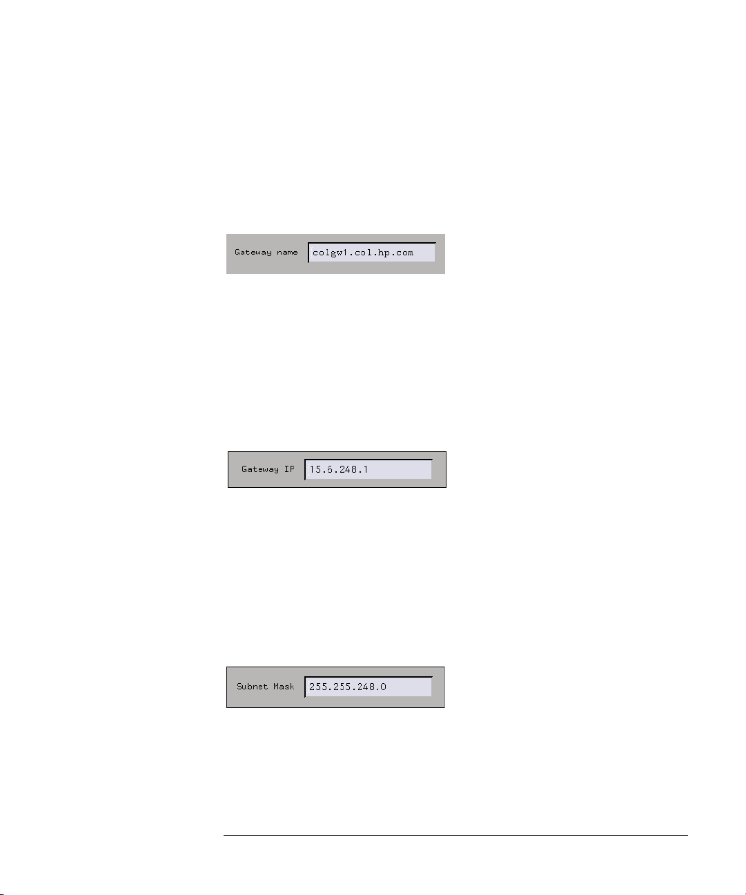
Gateway Name
The Gateway name is the name of the computer that routes traffic
22
Chapter 1: Agilent Technologies 16700A/B-Series Logic Analysis System
The System Administration Tools
from one network to another. If you plan to communicate with a
computer on a different network, you must specify the gateway
computer name. No entry in this field will disable the gateway. The
gateway name can contain only lowercase letters, numbers,
underscores(_), and dashes(-). It must start with a lowercase letter.
Get the gateway name from your system administrator.
Gateway IP
The Gateway IP is a four-part code in integer dot notation. The
assignment of the gateway IP allows the logic analysis system to
connect between other networks and subnetworks. The gateway IP
must be set to the address of the gateway machine. No entry in this
field will disable the gateway. Get the gateway address from your
system administrator.
Subnet Mask
The Subnet Mask is an assigned group of bits that helps to quickly
identify your subnetwork. If you have a gateway machine and your
network is partitioned into subnetworks, you must specify a subnet
mask. The subnet mask is a four-part code in integer dot notation. An
example of an 18-bit subnet mask is shown below. Get the subnet mask
from your system administrator.
Emulation Network Setup
Emulation probes, both standalone and interconnected to an emulation
module, need to be configured with LAN parameters.
23

Chapter 1: Agilent Technologies 16700A/B-Series Logic Analysis System
The System Administration Tools
The procedure for starting an connecting an emulation probe to the
network depends on which kind of emulator you are using:
• Setting Up an E5900A Emulation Probe (see the Emulation: Setting Up
help volume)
• Setting Up an E5900B Emulation Probe (see the Emulation: Setting Up
help volume)
• Setting Up an E5901B Emulation Module (see the Emulation: Setting Up
help volume)
An easy way to configure an emulation probe is to use the Setup
Assistant. Use the Setup Assistant if:
• You have a single E5900B emulation probe interconnected to an E5901B
emulation module, or
• You have an emulation probe and NO emulation module is installed in your
logic analysis system.
The Setup Assistant will not allow you to set up a standalone emulation
probe if an emulation module is installed.
See Also • Using an E5901A Emulation Module on Your LAN (see the Emulation:
Setting Up help volume)
• To obtain LAN information (see the Emulation: Setting Up help volume)
• The Setup Assistant (see the Setup Assistant help volume)
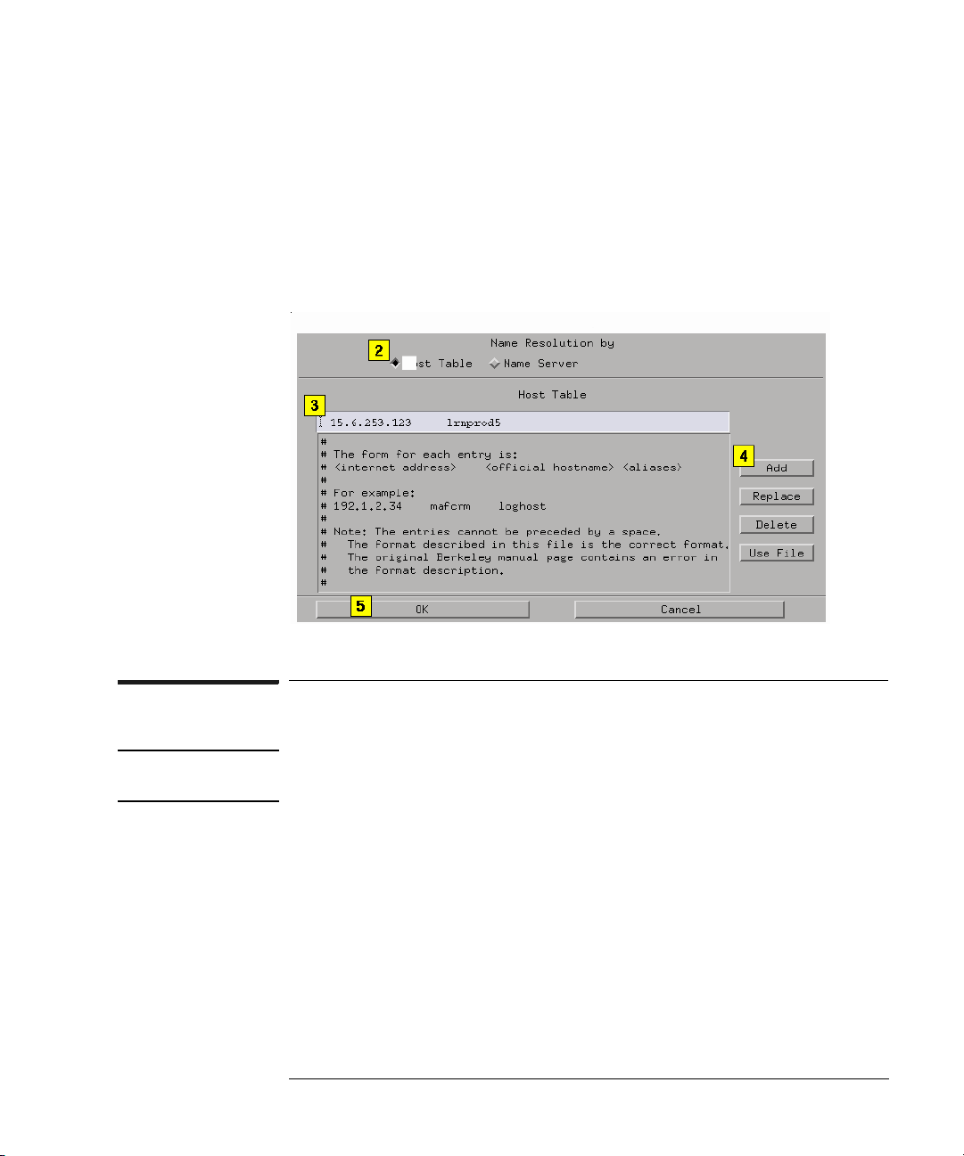
Using the Name Resolver to Alias IP Addresses
The Name Resolver is used to assign custom names (aliases) to the
Internet IP addresses. With an alias assigned to the Internet IP
Address, you simply type in the alias in any IP address field. The
configuration interprets it as the correct IP address. Alias names are
usually set in either a local Host Table or a Name Server on the
network.
1. From the Network Setup dialog, select Name Resolver....
2. In the Name Resolution Dialog, select Host Table and select the text entry
24
Chapter 1: Agilent Technologies 16700A/B-Series Logic Analysis System
The System Administration Tools
field for the alias names.
3. Type in the Internet IP Address (see page 22) followed by a space, and
then the alias name.
4. Select Add.
5. Select OK.
DHCP Network Setup
NOTE: This operation may require System Administration Privileges. (see
page 21)
DHCP (Dynamic Host Configuration Protocol) is a network protocol
that enables a DHCP server to automatically assign a dynamic IP
address to the logic analysis system.
If the logic analysis system is configured to use DHCP network
protocol, it is required that its hostname and gateway name be
provided on the nameserver for each DHCP client address and gateway
address so that it can be retrieved at boot time with nslookup.
If it is required that the logic analysis system have a consistent
hostname, use static DHCP with permanent leases.
25

Chapter 1: Agilent Technologies 16700A/B-Series Logic Analysis System
The System Administration Tools
Mapping Windows/NT Network Drives
The Map Windows Drive dialog is used to designate a share in a
Windows/NT computer to be available for file operations performed
from the logic analysis system.
NOTE: The logic analysis system only allows the use of one mapped directory per
server at a time. If more than one directory must be mapped, you must
disconnect the previously connected share before mapping the new one. Also,
do not disconnect a share mapping while files are being accessed. The
resulting file contention may cause long delays or an unstable logic analysis
system.
There are two ways to connect to a remote file system. One way is to
create a new connection. The other way is to reconnect to a previous
connection.
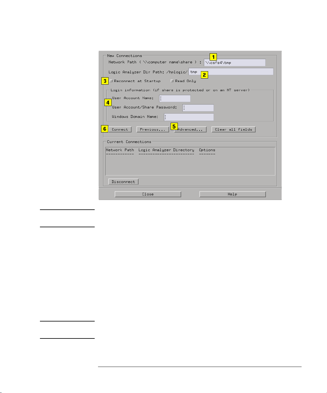
Creating a New Connection
1. Type in the Network Path (see page 28). The network path consists of the
IP address or the server name, followed by the specified share name.
2. Type in the Logic Analyzer Dir Path (see page 29).
3. Set the Reconnect at Startup (see page 28) as desired. When activated,
this feature automatically re-establishes the Windows/NT connectivity to
the logic analyzer directory at each new analyzer session startup.
Set the Read Only if necessary. See the note below.
4. Optional - Type in the Login Information (see page 29) if the share is
protected.
5. Optional - Select Advanced... to correct inconsistent naming (see
page 30) of the Windows netbios computer and the TCP/IP hostname.
6. Select Connect.
26
Chapter 1: Agilent Technologies 16700A/B-Series Logic Analysis System
The System Administration Tools
NOTE: If the CD-ROM you are using is shared from a Windows 95 server, the Read
Only field must be enabled.
Choose a Previous Connection
If a connection has been made in the past, the connection and its
options will appear in a dialog found by selecting the Previous...
button. To re-establish a previous connection, do the following.
1. Select Previous....
2. Select the desired connection from the list in the PC Previous Connections
dialog.
3. Select Select.
NOTE: For security reasons, password information is not saved when the Previous
dialog is used. In this case, you are required to re-enter Share passwords.
27

Chapter 1: Agilent Technologies 16700A/B-Series Logic Analysis System
The System Administration Tools
Disconnect a Current Connection
A list of Current Connections appears at the bottom of the dialog.
This is a list of all connections to remote file systems. If you
Disconnect a share mapping when either a file is still open, or a file
operation is in progress, the resulting file contention may cause long
delays or an unstable system. Terminate all file operations and
interaction with the remote file system before you disconnect the share
mapping.
To disconnect a share mapping, select the desired connection in the
Current Connections list, and then select Disconnect.
Reconnect at Startup
If you plan to reconnect at each startup, make sure to enable the
feature when you configure the connection the first time. This field
cannot be edited. The only way to change the configuration is to
disconnect, and then configure as a new connection. Also, be sure to
keep the connection active when you exit a session. In other words, do
not select the Disconnect field at the bottom of the dialog when you
exit a session.
NOTE: For security reasons, you cannot reconnect to a PC share map that is
password protected.
Network Path
What you type into the Network Path field will take the form
\\computer_name\share_name, where computer_name is the IP
address or name of the Windows server you are connecting to.
You can locate the computer name by right-clicking on Network
Neighborhood under the Windows system, then selecting Properties
from the pull-down menu. Locate the tab labeled Identification and
the Computer Name is specified there.
The share_name is the name that was specified for the Share Name in
the share dialog on the server where the share was created. To find the
Share Name under a Windows system, go to the drive where the share
is located, right-click on the directory, then select Sharing from the
28

Chapter 1: Agilent Technologies 16700A/B-Series Logic Analysis System
The System Administration Tools
pull-down menu. The share name is specified in the dialog that
appears.
Logic Analyzer Directory Path
The Logic Analyzer Dir Path points to the directory location in the
analyzer that is mapped to the Windows share. The directory is based
off of the main directory /logic/. The default name given to the subdirectory is the same as the Share Name designated in the Network
Path field.
NOTE: Some characters such as "$" are not allowed in UNIX filenames. If a Share
Name has one of these characters in its name, the default Logic Analyzer Dir
Path will be illegal, and you must change it manually.
Login Information
The Login Information is only required if the share is password or
account protected, that is, it is NOT a public share. If the share is a
Windows 95 share, with ONLY password protection, typically only the
User Account/Share Password field is required. If the share is a
Windows NT/95 share that is protected on a user account basis, the
User Account Name and User Account/Share Password fields are
both required. If the share is protected on a user account basis with NT
domain authentication, all fields are required.
User Account Name
This field allows the user to specify what his login account name is.
This is required for a share that has its permissions based on user
accounts.
User Account/Share Password
This field allows the user to specify the password for either his
account, or just the password for a share that is password protected.
Note that this field will display "*" characters as you type your
password for security purposes.
29

Chapter 1: Agilent Technologies 16700A/B-Series Logic Analysis System
The System Administration Tools
NOTE: If you are mapping to a Windows system, and after entering the User Account/
Share Password you have trouble connecting, try entering the Windows
Domain Name.
Windows Domain Name
This field allows the user to specify the name of the domain the user
account name should be authenticated under. This may be a necessary
field if the Windows server is using NT domain authentication.
Naming Server and Client Netbios Names
NOTE: This operation may require the help of your System Administrator
Use the Advanced... field to access a dialog used to correct naming
inconsistencies between the Windows netbios computer name and the
TCP/IP hostname of the same computer. The logic analysis system
must be provided with the name that is specified under the Windows
netbios environment.
For example, a Windows PC with the computer name of "testpc" is
connected to a TCP/IP network with an internet address of "joepc.company.com". Since "testpc" and "joe-pc" are different names, the
logic analysis system has no way of knowing the two names point to the
same computer.
Server Netbios Name
This field is used to specify the netbios name of the Windows server PC
with the share you wish to map. This name can be found by rightclicking on the Network Neighborhood icon on the server PC and
selecting Properties. The Identification tab in the dialog that appears
will show the name of the computer.
Client Netbios Name
This field is used to specify the netbios name of the logic analysis
system if it is different from the hostname specified in the Network
30

Chapter 1: Agilent Technologies 16700A/B-Series Logic Analysis System
The System Administration Tools
Setup dialog. You will need to contact your network administrator if
you do not know what the netbios name of the logic analysis system is.
NOTE: For convenience, it is usually easier to make sure these two names are the
same so the Advanced... field is not necessary.
Share Analyzer Drive
The Share Logic Analyzer Directory dialog is used to designate a
directory in the logic analysis system to be available for file operation
performed from a Windows/NT computer.
NOTE: If you are configuring a Windows/NT share for the first time, your system
administrator may have to set up the appropriate permissions and security
on the remote computer.
There are two ways to share a logic analysis directory to remote
Windows/NT systems. One way is to create a new share. The other way
is to reconnect to a previous share.
Creating a New Share
1. Type the directory name that you want accessible from a Windows/NT
computer.
The directory you choose must be a sub-directory based off of /logic/.
You can also use the Browse field to access a graphical file manager to
help in specifying a directory name.
2. Type in the Share Name (see page 33).
3. Optional - Type in a Share Comment (see page 33).
4. Set the Reshare at Startup as desired. When activated, this feature
automatically re-establishes the share connectivity to the remote
Windows/NT computer at each new analyzer session startup. See the note
below.
5. Optional - Type in a Share Password (see page 33), and then retype the
password to verify it was typed correctly.
31

Chapter 1: Agilent Technologies 16700A/B-Series Logic Analysis System
The System Administration Tools
6. Select Share.
NOTE: If you plan to Reshare at each startup, make sure to enable the feature, and be
sure to keep the share as a current active share. In other words, do not select
the UnShare field at the bottom of the dialog when you exit a session.
Choose a Previous Share
If a connection has been made in the past, the connection and its
options will appear in a dialog found by selecting the Previous...
button. To re-establish a previous Share, do the following.
1. Select Previous.
2. Select the desired Share from the list of PC Previous Connections.
3. Select Select.
NOTE: For security reasons, password information is not saved when the Previous
dialog is used. In this case, you are required to re-enter Share passwords.
32

Chapter 1: Agilent Technologies 16700A/B-Series Logic Analysis System
The System Administration Tools
Disconnect a Current Share
A list of Current Shares appears at the bottom of the dialog. This is a
list of all remote file system connections that are sharing the file
system of the logic analysis system. If you UnShare a share mapping
when either a file is still open, or a file operation is in progress, the
resulting file contention may cause long delays or an unstable system.
Terminate all file operations and interaction with the remote file
system before you disconnect the share mapping.
To disconnect a current share, select the desired connection in the
Current Shares list, then select UnShare.
Share Name
The Share Name is simply a literal name for the share. By default, a
name is assigned using the base name of the directory name. The base
name is the text to the right of the front-slash (/) in the path name.
Example:
If the directory name path you choose is /logic/test_1,
then the default Share Name would be test_1.
You can change the default name if you desire. Directory names can
only include the following alphanumeric characters:
0-9, a-z, A-Z, (-), (+), (_), (.), (/), and (:).
Share Comment
Use the Share Comments field to tag a Share directory with a desired
note. Any Share Comment you type, is displayed with the Share Name
when browsing the logic analyzer directories from a remote Windows/
NT computer.
Using a Share Password
If a Share Password is used, the user of the Windows/NT computer
will be prompted to type in the password before being allowed to
perform file operations in the logic analyzer directory.
NOTE: If no Share Password is used, the logic analyzer directory will have open
access with no file security.
33

Chapter 1: Agilent Technologies 16700A/B-Series Logic Analysis System
The System Administration Tools
Changing a Share Password
If a Share is set up to use a password, it will show up in the list of
currently active shares as being password protected. To change the
password on a currently active share, follow the procedure below.
To change an encrypted password, follow the procedure below.
1. Select the Share in the Current Shares list.
2. Select UnShare.
3. Select the Previous... field, and then select the Share from the list.
4. Type in a Share Password, and then retype the password to verify it was
typed correctly.
5. Select Share.
Configuring the NFS
The NFS Client Setup (Network File System) dialog lets you create
network connections to remote computers for the purpose of mounting
their file systems to your local logic analysis system.
The benefit of a mounted file system is that you can interact with the
remote directories/files using the File Manager in the logic analysis
system. You also have the benefit of using the disk space in the remote
computer rather than the disk space in the logic analysis system.
After an NFS connection is made, you will access the remote
directories/files under the /logic directory in the logic analysis system.
NOTE: If you are configuring an NFS mount for the first time, your system
administrator may have to set up the appropriate permissions and security
on the remote computer.
There are two ways to connect to a remote file system. One is to create
a new connection. The other is to reconnect to a previous connection.
34

Chapter 1: Agilent Technologies 16700A/B-Series Logic Analysis System
The System Administration Tools
Creating a New Connection
1. From the Networking tab in the System Administration Tools window,
select Mount NFS Filesystem ....
2. From the NFS Client Setup dialog that appears, type in the Remote host:
(see page 36) name. Optional - Use Browse Hosts... (see page 37) to select
a remote host and a remote directory path from a predefined list.
3. Type in the Remote dir path: (see page 36).
4. Type the Local dir path: (see page 36). Optional - Use Browse Local...
(see page 37) to select a directory path from a predefined list.
5. Choose the desired Options... (see page 37).
6. Select Mount.
Choose a Previous Connection
If a connection has been made in the past, the connection and its
options will appear in the NFS Previous Connections dialog, obtained
by selecting the Previous... button.
1. From the System Administration Tools window, select Mount NFS
filesystem....
2. From the NFS Client Setup dialog that appears, select Previous....
3. Select the desired connection from the NFS Previous Connections list.
4. Choose Select.
5. Select Mount.
By choosing from the NFS Previous Connections list, you
automatically get the defined options (see page 37) of that previous
connection.
Unmount a Current Connection
A list of Current Connections appears at the bottom of the NFS Client
Setup dialog. This is a list of all connections to remote file systems that
your logic analysis system is currently mounted to. If you try to
disconnect a mount when either a file is still opened by you, or a file
manager operation is still in progress, you will get a Device busy error.
35

Chapter 1: Agilent Technologies 16700A/B-Series Logic Analysis System
The System Administration Tools
Terminate all of your interaction with the mounted file system before
you disconnect the mount.
To unmount a current connection, select the desired connection in the
Current Connections list, then select Unmount.
Delete a Previous Connection
1. Select the Previous... button.
2. Select the unwanted connection, then select Delete.
See Also
“Mounting a ClearCase View” on page 37
Remote Host
The Remote host: field designates the remote computer’s name. It can
take the form of an alias, or a 4-part IP address integer. The remote
host name, plus the remote directory path, becomes the Network Path
listed in the Current Connections or NFS Previous Connections lists.
Remote Directory Path
The Remote dir path: field designates a directory path on the remote
machine. Type the remote directory path in the text field.
Example
/logic/test
Local Directory Path
The Local Directory field designates the local directory. If the local
directory you entered does not exist, a one-level directory is created
for you using the name you typed. Note that only one level will be
created automatically for you.
Example
/logic/test - where /test was created for you.
36

Chapter 1: Agilent Technologies 16700A/B-Series Logic Analysis System
The System Administration Tools
Options
• The Read/Write - Read only option determines if you can read or write to
the mounted file system.
If the exported file system is Read only, then you cannot have a Read/
Write option. It must be specified Read only.
• The Hard - Soft option determines if a request is continually repeated until
success (Hard), or if a request is made four (4) times, then aborts (Soft).
• The Reconnect at Startup options reconnects to the file system every
time the logic analysis system is turned on.
Using Browse Hosts
The Browse Hosts... field is used to access a predefined list of remote
host machine names and the directories that are mountable.
1. Select Browse Hosts...
2. From the Browse NFS Hosts dialog, either select a host name from the
upper list, or type in a host name in the text entry field.
3. Select Show Directories.
4. Select the desired directory, and then select Select.
Using Browse Local
The Browse Local... field accesses a Local Directory Browser similar
to a file manager. Use this Local Directory Browser to build a directory
path.
Mounting a ClearCase View
Using both the ability of Rational ClearCase to export views, and the
logic analysis system to NFS mount external file systems, you are now
able to access versioned source code to perform source correlation, use
symbols, and view data in trace listings.
37

Chapter 1: Agilent Technologies 16700A/B-Series Logic Analysis System
The System Administration Tools
NOTE: If you are mounting a Rational ClearCase view for the first time, your system
administrator may have to set up the appropriate permissions and security
on the remote view server.
There are two ways to connect to a Rational ClearCase view. One is to
create a new connection, the other is to reconnect to a previous
connection.
To Mount a New ClearCase View
1. Enter the name of your Remote View Server.
2. Optional - If not sure of the Remote View Server name, select Browse View
Servers... (see page 39) and use the graphical interface to select the
appropriate View Server and view.
3. Enter the ClearCase Remote View Name.
4. Select the Options... button and set the desired Options.
5. Select the Mount button.
To Mount a Previous ClearCase View
If a connection has been made in the past, the connection and its
options will appear in the Previous Connections dialog.
1. Select the Previous... button.
2. From the list of previous connections that appear, select the desired view
name.
3. Choose the Select button.
4. Select the Mount button.
By choosing a Previous Connection, you automatically get the defined
Options (see page 37) of that previous connection.
Unmount a Current View
Current Views lists all currently mounted views. If you try to unmount
38

Chapter 1: Agilent Technologies 16700A/B-Series Logic Analysis System
The System Administration Tools
a view when a file is still open, or a file manager operation is still in
progress, you will get a Device Busy error. Terminate all interactions
with the view before you unmount it.
To unmount a ClearCase connection, simply select the view name from
the Current Views list, then select the Unmount button.
Delete a Previous View
1. Select the Previous... button.
2. Select the unwanted view, then select Delete.
See Also
“Overview of Source Correlation with Rational ClearCase” on page 40
“Rational ClearCase Copyright Information” on page 40
Using Browse View Servers
Use Browse View Servers... to access a predefined list of remote view
server names and the views that are mountable.
1. Select Browse View Servers...
2. From the Browse View Servers dialog, either select a view server name
from the upper list, or type in a view server name in the text entry field.
3. Select Show Views.
4. Select the desired view, then choose Select.
The Remote View Server Name
The Remote view server field designates the remote computer’s name.
The name can take the form of either a pre-defined alias, or a 4-part IP
address integer. The Remote view server name, plus the Remote view
name, becomes the Network Path listed in the Current Connections or
Previous Connections lists.
The Remote View Name
The Remote view name field designates the view tag, or name of the
39

Chapter 1: Agilent Technologies 16700A/B-Series Logic Analysis System
The System Administration Tools
ClearCase view you created.
Overview of Source Correlation with Rational ClearCase
For a complete overview, refer to the file:
"Using16700withClearCase.pdf"
located at:
/logic/demo/SW_Cfg_Mgmt/ClearCase/
Rational ClearCase Copyright Information
Copyright 1992,1999 Rational Software Corporation, All rights
reserved.
FTP (file transfer protocol)
Once you have established an FTP (file transfer protocol) connection,
you can perform FTP commands on files in both the logic analysis
system and a remote workstation, PC. If you are in Secure Mode, you
can only perform FTP commands from the logic analysis system.
The following example copies a password file to a remote system, and
then copies it back to the logic analysis system.
1. From the Networking tab in the System Administration Tools window,
select FTP ....
2. In the FTP Site dialog that appears, type the alias name or IP address of
the remote workstation, PC, or other logic analysis system, and select OK.
See the note below.
3. In the FTP window that appears, type your Login, and press the Enter key.
4. Type in your Password, and press the Enter key.
5. From the ftp window that appears, copy the example file
"password.example" to a directory in the remote system. For example: put
/local_etc/password.example /"remote_dir_name"/.
6. Copy the file back to the logic analysis system. For example: get /
40

Chapter 1: Agilent Technologies 16700A/B-Series Logic Analysis System
The System Administration Tools
"remote_dir_name"/"new_filename" /local_etc/.
To Terminate the FTP Session
To terminate your FTP connection, type "quit".
NOTE: Alias names that are not located in /etc/host on your remote machine may not
be recognized by the logic analysis system. If this is the case, use the Internet
IP address instead of the alias name.
FTP Connection from PC to Logic Analysis System
Use this procedure if you want to make an FTP connection from a
remote PC or Workstation to the logic analysis system.
NOTE: An FTP connection from a remote PC or Workstation is not allowed when the
logic analysis system is in Secure Mode.
1. From the command line of your remote computer, type: ftp
"machine_name".
2. For the login name, use "anonymous".
3. For the password, use "nopass".
Telne t
The ability to Telnet (connect) to other workstations, PCs, or logic
analysis systems lets you run and view programs resident to these
remote machines. As an example, you can run multiple logic analysis
systems from the same display.
When identifying a remote machine during a telnet login process, you
can use either the Internet IP address (see page 22), or a predefined
alias name (see page 24). If you use an alias name, see the note below.
The following example shows how to Telnet to a remote logic analysis
system and display its session on your local logic analysis system.
1. From the system window in your local logic analysis system, select the
System Administration icon. Then from the Networking tab in the
41

Chapter 1: Agilent Technologies 16700A/B-Series Logic Analysis System
The System Administration Tools
System Administration Tools window, select Te ln e t . . ..
2. Type the name of the remote logic analysis system, and select OK.
3. From the Telnet window that appears, type "logic", and press the Enter
key.
NOTE: "logic" will not work if the remote logic analysis system is in Secure Mode. In
this case, enter a login and password that is within the user accounts (see
page 57) of the remote logic analysis system.
4. From the Session Manager dialog of the new remote session, select
Display Session on Another Display.
5. From the Remote Setup dialog that appears, type the name of the local
display, and select Start.
To Terminate the Telnet Session
To terminate your remote session, select Exit in the remote System
window. Then from the remote Session Manager window, select
Disconnect. This will remove both the remote System window and
Session Manager window from the local display.
NOTE: Alias names that are not located in /etc/host on your local machine may not be
recognized by the logic analysis system. If this is the case, use the Internet IP
address instead of the alias name.
Ping
Ping is a utility to check LAN communication with remote hosts. To
ping a remote host, simply type in the remote host machine name and
select OK.
To stop the pinging, type control-C.
42

Chapter 1: Agilent Technologies 16700A/B-Series Logic Analysis System
The System Administration Tools
Licensing Policy for the Logic Analysis System
License Policy:
Select logic analysis system product software is licensed for single use
only. Licenses are nodelocked and are valid for the life of the product.
Software updates do not affect the license.
Nodelock Mode:
Product licenses are shipped or first installed in nodelock mode.
Nodelock mode allows use of the product license only on the node
(HP 1670xA/B-Series logic analyzer) on which it is installed. Products
ordered with a logic analysis system will be installed and ready to run.
Products purchased aftermarket will require customers to access
Agilent’s password redemption Web site to obtain the appropriate
passwords. The Web site URL and alternate contact instructions are
provided on the Entitlement Certificate shipped with the licensed
product.
Temporary Licenses:
In most instances, a single temporary (demo ) license is available for
any product not previously licensed on a node. The temporary license
is valid for the number of calendar days specified in the Demo Time
column. The demo time starts from first entry of the password in the
license management window. The temporary password for any node on
any tool set is "demo".
License Management:
Licenses are managed from the License Management window, obtained
by selecting Licensing... under the Admin tab in the System
Administration Tools window. License management does not require
Unix expertise. Licenses are reserved at the start of a measurement
session. They remain in use (reserved) until the measurement session
is terminated.
Password Backup:
Passwords can be backed up to floppy disk by selecting Save... under
43

Chapter 1: Agilent Technologies 16700A/B-Series Logic Analysis System
The System Administration Tools
the Admin tab in the System Administration Tools window. Passwords
can only be restored on the logic analysis system where they were
initially installed in nodelock mode.
Printing Windows - Configurations
The print windows operation lets you print either the current window,
all currently open windows, or just a selected window. Also if you are in
the Listing Display window, you can print data to a file.
NOTE: When printing windows to a printer, only the currently displayed viewing area
of the window or computer screen is printed. If any data or configuration
fields appear off-screen, scroll the desired data or configuration fields into the
window’s viewing area before printing.
Print this window
Print this window prints the current window.
Print all windows
Print all windows prints all open windows. This option is only
available in the Workspace window.
Print any window
Print any window prints any open window that you select to make
active.
Print to file
Print to file prints data from the Display tool to a file. This option is
only available in the Listing Display window.
See Also Setting Print Options (see page 47)
Setup the Printer (see page 45)
44

Chapter 1: Agilent Technologies 16700A/B-Series Logic Analysis System
The System Administration Tools
Printer Setup
Local Printer Setup
1. From the Admin tab in the System Administration Tools window, select
Printers ....
2. From the Printer Setup dialog that appears, select Local.
3. In the Printer type pulldown, select the printer type you are connecting.
4. Select OK.
Network Printer Setup
Use this procedure if you are using a Unix print server. If you are using
a Windows NT print server, select this link. (see page 46)
1. From the Admin tab in the System Administration Tools window, select
Printers ....
2. From the Printer Setup dialog that appears, select Network.
3. Type in the recognized Printer name. See the note below.
4. Type in the recognized Print Server name. In addition to being listed in a
network host table, the print server name must be listed in the host table
(see page 24) in the logic analysis system.
5. In the Printer type pulldown, select the printer type you are connecting.
6. Select OK.
45

Chapter 1: Agilent Technologies 16700A/B-Series Logic Analysis System
The System Administration Tools
NOTE: Consult your system administrator for the required printer name and print
server name. These names should be located in the network’s host table or
name server. The print server name must also be listed in the host table (see
page 24) in the logic analysis system.
Windows NT Server Configuration
From the Windows Interface:
1. From the Main file group, select Control Panel, then Network.
2. Select the Services tab.
3. Select Add..., select TCP/IP Printing, then select OK. At this point, NT
will automatically install the Berkeley Unix LPD print server.
4. From the Control Panel, select Services.
5. From the Services control panel, select TCP/IP Print Server, then select
Startup....
6. Change Startup Type to Automatic.
7. Configure your printers on the NT machine as you normally would.
From the System Administration Tools Window:
NOTE: Do not put white space in the printer name.
1. From the Admin tab in the System Administration Tools window, select
Printers ....
46

Chapter 1: Agilent Technologies 16700A/B-Series Logic Analysis System
The System Administration Tools
2. Select Network.
3. Type in the recognized Printer name. See the note below.
4. Type in the recognized Print Server hostname. In addition to being listed
in a network host table, the print server name must be listed in the host
table (see page 24) in the logic analysis system.
5. Select Yes to Berkeley UNIX server.
6. In the Printer type pulldown, select the printer type you are connecting.
7. Select OK.
NOTE: Consult your system administrator for the required printer name and print
server name. These names should be located in the network’s host table or
name server. The print server name must also be listed in the host table (see
page 24) in the logic analysis system.
Print Options
The Print Window Options dialog lets you set print destination, file
format type, filename autoincrement, and color/b&w; pixel mapping.
1. In the tool window menu bar, select File, then Print options.
2. From the Print Window Options dialog, select the destination as either
Printer or File.
47

Chapter 1: Agilent Technologies 16700A/B-Series Logic Analysis System
The System Administration Tools
3. If Printer is selected, configure the Printer Setup (see page 45) dialog.
4. If File is selected, type in the path and filename. You can also select
Browse and use the File Manager dialog to browse for a path and filename.
5. Optional - If File is selected, autoincrement (see page 48) the filename.
6. Optional - If File is selected, select the file format type.
7. Set the Pixel Mapping (see page 49) to Color or Black & White.
8. Set the Orientation to Landscape or Portrait.
9. Select Close.
See Also “Printing Windows - Configurations” on page 44
“Printer Setup” on page 45
“Windows NT Server Configuration” on page 46
Autoincrement filenames
Use the Autoincrement feature when you are saving multiple files, and
you don’t want to type in a new filename for each new file. As files are
saved, the base filename remains the same with only the extension
being incremented.
Example
filename.0
filename.1
48

Chapter 1: Agilent Technologies 16700A/B-Series Logic Analysis System
The System Administration Tools
filename.2
filename.3
Pixel mapping
Use the pixel mapping feature when you want to print a faxable black
and white hardcopy.
Configuring the System Clock
NOTE: This operation may require System Administration Privileges. (see
page 21)
1. From the System Administration Tools window, select Time/Date....
2. Select in the desired value field, and backspace or delete the current
numbers.
3. Type the new values, and select OK. At this point, you are asked to reboot
the logic analysis system.
Running the Self Tests
The Self Test function of the logic analysis system performs functional
tests on both the System and any installed modules.
1. From the Admin tab in the System Administration Tools window, select
Self-Test....
2. Read the Question dialog and select Yes if you wish to run the self tests.
3. From the Self Test window, select the desired area to test by selecting the
appropriate tab. Your choices are either the System boards, modules in the
Master Frame, or modules in the optional Expander Frame.
4. Run the tests in one of the following ways:
• Test All – To test all boards or modules under a tab, select Tes t Al l at
the bottom of the Self Test window.
49

Chapter 1: Agilent Technologies 16700A/B-Series Logic Analysis System
The System Administration Tools
• Test a single board or module – To test a single board or module under
a tab, select the desired board or module, and then select either a
single component or select Te s t A l l at the bottom of the board or
module test dialog.
5. When you are finished running self tests, select Quit. Then restart your
session from the Session Manager window.
NOTE: For complete information on self tests, test options, troubleshooting, and
service procedures, refer to the optional service guides available for the
system or the desired modules.
See Also “More on Self Tests” on page 50
More on Self Tests
Self Test lets you get confidence that the hardware is configured and
operating correctly, and enables the HP factory to test the product.
Self Tests and Session Management
When Self Test is entered, the current measurement session is exited.
You are warned of this prior to entering Self Test so you can save any
important data and configurations. The closure of the measurement
session is necessary because Self Test leaves the hardware in an
unknown state when it is finished. Restarting the measurement session
is then required to properly initialize the hardware.
Testing Multi-Card Modules
Under each tab is a list of boards or measurement modules. When
selected, each individual board or module lists a set of its own
individual tests. Some measurement modules are composed of multiple
cards where one card is called the master and the others are called
expanders. Self tests for a multiple card set are always tested through
the master card. Test results for the expander cards will track results
for the master card. In some cases, the self tests can identify a problem
to either an expander or master card. In this case, the failure counts
shown on an expander card may differ from those shown for a master
card.
50

Chapter 1: Agilent Technologies 16700A/B-Series Logic Analysis System
The System Administration Tools
Test Options
Test options are set from the Options pulldown in the menu bar. They
are provided only as a convenience to the user. They are intended for
factory use only.
User Action Required
When running "All Tests", some of the tests may have a test result of
"Not executed". In some cases, this message is because the test does
not apply to the current hardware configuration. In other cases, it
indicates the test requires some type of user action. These tests should
be individually selected, and when user action is required, a dialog will
appear to direct the user. The tests that require user action are listed
below.
CPU Board
• Floppy Drive Test: A DOS formatted floppy must be in the drive.
• External SCSI Test: A powered-up CD-ROM drive must be on the bus.
HP16517A Timing Module
• Skew Adjust: Not a test; used for calibration.
HP16522A Stimulus Module
• Output Stimulus Vectors: Not a test; provides continuous signal output.
HP16534A Scope Module
• ADC Test: There must be no stimulus on the scope inputs.
HP16550 State and Timing Module
• Show Activity: Not a test; provides continuous output of signal input
levels.
HP16610A Emulator Module
• Internal PV Test: A loop back connector must be installed.
NOTE: For complete information on self tests, test options, troubleshooting, and
service procedures, refer to the optional service guides available for the
system or the desired modules.
51

Chapter 1: Agilent Technologies 16700A/B-Series Logic Analysis System
The System Administration Tools
Saving and Reloading System Settings
The Save System Settings and Load System Settings fields are
located under the Admin tab of the System Administration Tools
dialog. By saving your system settings to a flexible disk or a mounted
directory, you create a backup file that can be used to quickly setup
new systems, or restore a current system’s settings after a re-ignite
procedure (see page 52).
To save or reload your system settings, select the desired items, then
select Save to File, or Load Settings. If an item is not valid, or was not
initially saved to the file, the selection is greyed out in the interface.
Also, a .set file extension is automatically added for you.
Flexible Disk Backup - Re-ignite
NOTE: Unless changed in the file browser, the flexible disk is the default drive when
saving a backup file. If you are going to re-ignite your logic analysis system,
you MUST save the settings to the flexible disk or a mounted directory. Files
saved on the analyzer’s hard disk will be lost during the re-ignite procedure
(see page 52).
What System Settings are Saved
• Printer Settings (see page 53)
• Network Settings (see page 53)
• User Account Information (see page 55)
• License Information (see page 56)
• Custom Color Settings (see page 56)
• Web Settings (see page 56)
• Session Manager (see page 56)
• E-mail on Trigger (see page 57)
Re-ignite Procedure
The re-ignite procedure is a process used to restore the operating
52

Chapter 1: Agilent Technologies 16700A/B-Series Logic Analysis System
The System Administration Tools
system to the hard disk. Since user configurations, data files, and
license passwords are lost during this procedure, it is recommended
that you save the system settings to a backup flexible disk or a
mounted directory.
Printer Settings
Printer settings are located under the Printers... field on the Admin
tab of the System Administration Tools dialog.
• Printer Local or Network
• Network - Printer Name
• Network - Server Name
• Is print server Berkeley UNIX - No/Yes
• Printer Type
NOTE: Information in the Printer Queue, and any Print Options (see page 47) are not
saved.
Network Settings
Network settings are located on the Networking tab of the System
Administration Tools dialog.
Network Setup...
• Networking - Enable/Disable
• Hostname
• Internet Address (IP)
• Gateway Name
• Gateway IP
• Subnet Mask
• All Name Resolver... information
53

Chapter 1: Agilent Technologies 16700A/B-Series Logic Analysis System
The System Administration Tools
Map 95/NT Network Drive...
NOTE: The following information is only saved if the Reconnect at Startup option is
enabled.
• Network Path
• Logic Analyzer Dir Path
• Reconnect at Startup
• Read only
• All Current Connections information
Share Analyzer Drive...
NOTE: The following information is only saved if the Reshare at Startup option is
enabled.
• Logic Analyzer Dir to Share
• Share Name
• Share Comment
• Reshare at Startup
• All Share Password information
• All Current Shares information
Mount NFS Filesystem...
NOTE: The following information is only saved if Reconnect at Startup under the
Options... field is enabled.
• Remote Host
• Remote Dir Path
• Local Dir Path
• All NFS Options information
• All Current Connections information
54

Chapter 1: Agilent Technologies 16700A/B-Series Logic Analysis System
The System Administration Tools
Network Services
Even though Network Services is found under the Security tab of the
System Administration Tools dialog, the following settings are saved
under the Network settings selection.
• Web Server
• Shared Console (VNC)
• Remote Programming Interface
• pcnfsd (for PC NFS)
User Accounts
User Accounts settings are located on the Security tab of the System
Administration Tools dialog. In addition to the user account directory
structure, the following settings are saved:
NOTE: If you save user accounts while you are in secure mode, after you load this
system settings file, you will be in secure mode. Because of this, it is very
important that you know a sys user and his password before loading a secure
saved user account file. Similarly, if you save user accounts while you are not
in secure mode, after you load the system settings file, you will not be in
secure mode.
User Accounts...
• Secure Mode - Disabled/Enabled
• All current accounts information
• User-specific custom colors
• User-specific Web bookmarks and Web preferences
NOTE: It should be noted that no specific user account data is saved.
Network Services
Even though Network Services is found under the Security tab of the
System Administration Tools dialog, the following settings are saved
under the Network settings selection.
55

Chapter 1: Agilent Technologies 16700A/B-Series Logic Analysis System
The System Administration Tools
• Web Server
• Shared Console (VNC)
• Remote Programming Interface
• pcnfsd (for PC NFS)
Licenses
License information can only be saved and reloaded on the same logic
analysis system. If you are setting up new logic analysis systems using a
backup system settings file, all settings can be loaded except the
license information. However, if you are performing the re-ignite
procedure (see page 52) to the same logic analysis system, all settings
including the license information can be reloaded.
Custom Colors
The custom color settings saved are the system colors located in the
Waveform and Listing Tool’s menu bar Edit - Set default attributes....
In the Distribution and Chart tool, system colors are located under
Options - Color.
Custom colors for users in Secure Mode are saved and restored with
the User Accounts (see page 55) selection.
Web Settings
If you are using the logic analysis system in a stand-alone unsecured
mode, the following settings are saved.
• Bookmarks
• Preferences
Bookmarks and Preferences for users in Secure Mode are saved and
restored with the User Accounts (see page 55) selection.
Session Manager Settings
The following Session Manager settings are saved and restored with the
Network Setup (see page 53) selection.
56

Chapter 1: Agilent Technologies 16700A/B-Series Logic Analysis System
The System Administration Tools
• Window size
• Exclusive or Shared session
E-mail on Trigger Settings
You configure the e-mail on trigger from within a Sequence level under
the Trigger Tab in the analyzer tool. The only setting that is saved is
the SMTP server name, and it is saved and restored with the Network
Setup (see page 53) selection.
Setting Up User Accounts
When you power up the instrument for the first time, you are in an
open-networked unsecured mode. Any user can access the logic
analysis system and store data with no record of access. By definition,
you are in the open-networked mode when Secure Mode is disabled.
User accounts are useful when large project teams share lab
equipment. In this environment, one or more users are set up with a
user account and given a login and password. User accounts add the
security of restricted use, plus the ability to trace all network activity
and file ownership. By definition, you are in the secured user accounts
mode when your System Administrator enables the Secure Mode field.
For more information on the user environment, refer to The User
Environment and Session Control (see page 100).
The default factory configuration is the open-networked unsecured
mode. Use the following procedures to set up user accounts and add
security to your system through the Secure Mode. You can set up user
accounts either individually, or by importing a file.
NOTE: Any user can set up user accounts and become the system administrator the
first time the User Accounts dialog is accessed. To modify user account after
Secure Mode has been enabled, System Administration Privileges. (see
page 21) are required.
57

Chapter 1: Agilent Technologies 16700A/B-Series Logic Analysis System
The System Administration Tools
Adding User Accounts Individually
1. From the Security tab in the System Administration Tools window, select
User Accounts...
2. At the bottom on the window, select Add....
3. From the Add-User Account dialog, type in the user’s Login Name.
4. Type in the user’s Password (see page 60), and then the user’s Password
Again.
5. Optional – Type in the user's Encrypted Password.
6. Optional - Type in a Password Age (see page 60).
7. Type in the User Identity and Group Identity.
8. Type in the user's Real Name.
9. Select the File Permissions (see page 102) field, and select the desired
system default read/write permissions.
10. Optional – Check Has Admin Privileges if you want to give the new user
System Administrator privileges.
11. Select Add. Repeat the above from step 3 for the next user account, or,
select Cancel to exit the dialog.
12. Toggle the Secure Mode field to Enabled. Enabling this field will activate
the use of user accounts and set the system to a secured team use
environment.
13. Select OK to close the User Accounts dialog.
14. At this point, you will be asked to verify the reboot of the logic analysis
system. A reboot is necessary to implement the system level change of the
secured user accounts mode.
Adding User Accounts by Importing a File
If you have multiple users that require user accounts, it might be easier
to simply import a password file. If you plan to import password files,
the files must follow the specified format for a password file. An
example of a password file with the specified format is located in "/
local_etc/" in the File Manager window.
58

Chapter 1: Agilent Technologies 16700A/B-Series Logic Analysis System
The System Administration Tools
You can use the example password file to generate your own file. Copy
the file to a word processor, edit the file, and then copy it back to the /
local_etc/ directory under a new name. For an example of copying files
to other systems, refer to FTP (file transfer protocol) (see page 40).
1. From the Security tab in the System Administration Tools window, select
User Accounts...
2. Select Import.... Then from the Import Account Dialog that appears, select
the Default File Permissions (see page 102) field and set the desired
system default read/write permissions.
3. Select Import File. From the file browser that appears, select the file
name to import, and select OK.
4. From the Import Account dialog, select OK.
5. From the User Accounts dialog, edit the desired accounts giving at least
one user system administration privileges.
6. Toggle the Secure Mode field to Enabled. Enabling this field will activate
the use of user accounts and set the system to a secured team use
environment.
7. Select OK.
8. At this point, you will be asked to verify the reboot of the logic analysis
system. A reboot is necessary to implement the system level change of the
secured user accounts mode.
Enabling/Disabling User Accounts
Once you have a list of user accounts in the system, your System
Administrator can enable or disable user accounts by toggling the
Secure Mode field. When you change the working mode, you will be
asked to power down the system, and then power it back up. This
enables the network to identify the new working mode.
Editing the User Accounts List
To delete a user from the accounts list, select the desired User
Account, and select Delete.
To modify user information in the accounts list, select the desired User
Account, make the appropriate changes in the Account Information
59

Chapter 1: Agilent Technologies 16700A/B-Series Logic Analysis System
The System Administration Tools
dialog, and then select Modify.
Legal Passwords
• Passwords must be at least 6 characters long.
• Passwords cannot be circular shift of your login ID.
• Old and new passwords must differ by at least 3 positions.
Passwd Man Page
The following man page documents the use of a password file.
NAME
passwd - password file, pwd.h
DESCRIPTION
passwd contains the following information for each user:
+ login name
+ encrypted password
+ numerical user ID
+ numerical group ID
+ reserved field, which can be used for identification
+ initial working directory
+ program to use as shell
This is an ASCII file. Each field within each user’s entry is
separated from the next by a colon. Each user is separated from the
next by a newline. This file resides in the /etc directory. It can
and does have general read permission and can be used, for example, to
map numerical user IDs to names. If the password field is null and
the system has not been converted to a trusted system, no password is
demanded.
If the shell field is null, /usr/bin/sh is used.
The encrypted password consists of 13 characters chosen from a 64 character set of "digits" described below, except when the password is
null, in which case the encrypted password is also null. Login can be
prevented by entering in the password field a character that is not
part of the set of digits (such as *).
The characters used to represent "digits" are . for 0, / for 1, 0
through 9 for 2 through 11, A through Z for 12 through 37, and a
through z for 38 through 63.
PASSWORD AGE
Password aging is put in effect for a particular user if his encrypted
password in the password file is followed by a comma and a nonnull
string of characters from the above alphabet. (Such a string must be
introduced in the first instance by a superuser.) This string defines
the "age" needed to implement password aging.
The first character of the age, M, denotes the maximum number of weeks
for which a password is valid. A user who attempts to login after his
password has expired is forced to supply a new one. The next
character, m, denotes the minimum period in weeks that must expire
before the password can be changed. The remaining characters define
the week (counted from the beginning of 1970) when the password was
last changed (a null string is equivalent to zero). M and m have
numerical values in the range 0 through 63 that correspond to the 64-
60

Chapter 1: Agilent Technologies 16700A/B-Series Logic Analysis System
The System Administration Tools
character set of "digits" shown above. If m = M = 0 (derived from the
string . or ..), the user is forced to change his password next time
he logs in (and the "age" disappears from his entry in the password
file). If m > M (signified, for example, by the string ./), then only
a superuser (not the user) can change the password. Not allowing the
user to ever change the password is discouraged, especially on a
trusted system.
Trusted systems support password aging and password generation. For
more information on converting to trusted system and on password, see
the HP-UX System Administration Tasks Manual and sam(1M).
getpwent(3C) designates values to the fields in the following
structure declared in <pwd.h>:
struct passwd {
char *pw_name;
char *pw_passwd;
uid_t pw_uid;
gid_t pw_gid;
char *pw_age;
char *pw_comment;
char *pw_gecos;
char *pw_dir;
char *pw_shell;
aid_t pw_audid;
int pw_audflg;
};
It is suggested that the range 0-99 not be used for user and group IDs
(pw_uid and pw_gid in the above structure) so that IDs that might be
assigned for system software do not conflict.
The user’s full name, office location, extension, and home phone
stored in the pw_gecos field of the passwd structure can be set by use
of the chfn command (see chfn(1)) and is used by the finger(1)
command. These two commands assume the information in this field is
in the order listed above. A portion of the user’s real name can be
represented in the pw_gecos field by an & character, which some
utilities (including finger) expand by substituting the login name for
it and shifting the first letter of the login name to uppercase.
SECURITY FEATURES
On trusted systems, the encrypted password for each user is stored in
the file /tcb/files/auth/c/user_name (where c is the first letter in
user_name). Password information files are not accessible to the
public. The encrypted password can be longer than 13 characters .
For example, the password file for user david is stored in
/tcb/files/auth/d/david. In addition to the password, the user
profile in /tcb/files/auth/c/user_name also contains:
+ numerical audit ID
+ numerical audit flag
Like /etc/passwd, this file is an ASCII file. Fields within each
user’s entry are separated by colons. Refer to authcap(4) and
prpwd(4) for details. The passwords contained in /tcb/files/auth/c/*
take precedence over those contained in the encrypted password field
of /etc/passwd. User authentication is done using the encrypted
passwords in this file . The password aging mechanism described in
passwd(1), under the section called SECURITY FEATURES, applies to this
password .
NETWORKING FEATURES
NFS
The passwd file can have entries that begin with a plus (+) or minus
(-) sign in the first column. Such lines are used to access the
Network Information System network database. A line beginning with a
plus (+) is used to incorporate entries from the Network Information
System. There are three styles of + entries:
+ Insert the entire contents of the Network Information
61

Chapter 1: Agilent Technologies 16700A/B-Series Logic Analysis System
The System Administration Tools
System password file at that point;
+name Insert the entry (if any) for name from the Network
Information System at that point
+@name Insert the entries for all members of the network
group name at that point.
If a + entry has a nonnull password, directory, gecos, or shell field,
they override what is contained in the Network Information System.
The numerical user ID and group ID fields cannot be overridden.
The passwd file can also have lines beginning with a minus (-), which
disallow entries from the Network Information System. There are two
styles of - entries:
-name Disallow any subsequent entries (if any) for name.
-@name Disallow any subsequent entries for all members of
the network group name.
WARNINGS
User ID (uid) 17 is reserved for the Pascal Language operating system.
User ID (uid) 18 is reserved for the BASIC Language operating system.
These are operating systems for Series 300 and 400 computers that can
coexist with HP-UX on the same disk. Using these uids for other
purposes may inhibit file transfer and sharing.
The login shell for the root user (uid 0) must be /sbin/sh. Other
shells such as sh, ksh, and csh are all located under the /usr
directory which may not be mounted during earlier stages of the bootup
process. Changing the login shell of the root user to a value other
than /sbin/sh may result in a non-functional system.
The information kept in the pw_gecos field may conflict with
unsupported or future uses of this field. Use of the pw_gecos field
for keeping user identification information has not been formalized
within any of the industry standards. The current use of this field
is derived from its use within the Berkeley Software Distribution.
Future standards may define this field for other purposes.
The following fields have character limitations as noted:
+ Login name field can be no longer than 8 characters;
+ Initial working directory field can be no longer than 63
characters;
+ Program field can be no longer than 44 characters.
+ Results are unpredictable if these fields are longer than the
limits specified above.
The following fields have numerical limitations as noted:
+ The user ID is an integer value between -2 and UID_MAX
inclusive.
+ The group ID is an integer value between 0 and UID_MAX
inclusive.
+ If either of these values are out of range, the getpwent(3C)
functions reset the ID value to (UID_MAX).
EXAMPLES
NFS Example
Here is a sample /etc/passwd file:
root:3Km/o4Cyq84Xc:0:10:System Administrator:/:/sbin/sh
joe:r4hRJr4GJ4CqE:100:50:Joe User,Post
4A,12345:/home/joe:/usr/bin/ksh
+john:
62

Chapter 1: Agilent Technologies 16700A/B-Series Logic Analysis System
The System Administration Tools
-bob:
+@documentation:no-login:
-@marketing:
+:::Guest
In this example, there are specific entries for users root and joe, in
case the Network Information System are out of order.
+ User john’s password entry in the Network Information System
is incorporated without change.
+ Any subsequent entries for user bob are ignored.
+ The password field for anyone in the netgroup documentation
is disabled.
+ Users in netgroup marketing are not returned by getpwent(3C)
and thus are not allowed to log in.
+ Anyone else can log in with their usual password, shell, and
home directory, but with a pw_gecos field of Guest.
NFS Warnings
The plus (+) and minus (-) features are NFS functionality; therefore,
if NFS is not installed, they do not work. Also, these features work
only with /etc/passwd, but not with a system that has been converted
to a trusted system. When the system has been converted to a trusted
system, the encrypted passwords can be accessed only from the
protected password database, /tcb/files/auth/*/*. Any user entry in
the Network Information System database also must have an entry in the
protected password database.
The uid of -2 is reserved for remote root access by means of NFS. The
pw_name usually given to this uid is nobody. Since uids are stored as
signed values, the following define is included in <pwd.h> to match
the user nobody.
UID_NOBODY (-2)
FILES
/tcb/files/auth/*/* Protected password database used when
system is converted to trusted system.
/etc/passwd Standard password file used by HP-UX.
SEE ALSO
chfn(1), finger(1), login(1), passwd(1), a64l(3C), crypt(3C),
getprpwent(3), getpwent(3C), authcap(4), limits(5).
STANDARDS CONFORMANCE
passwd: SVID2, SVID3, XPG2
Change Password
You do not require system administration privileges to change your
password.
1. From the Security tab in the System Administration Tools window, select
Change Password...
2. If your account previously had a password, you will enter it in the Old
Password field.
63

Chapter 1: Agilent Technologies 16700A/B-Series Logic Analysis System
The System Administration Tools
3. Enter your new password (see page 60) in the New Password field.
4. Enter it again in the New Password Again field.
5. Select OK.
Web Server Security
Use this selection to allow or prevent access to the web page of this
logic analysis system from other workstations or personal computers.
• Select On if you wish to allow other workstations and personal computers
to access the home page of this logic analysis system.
• Select Off to prevent other workstations and personal computers from
accessing the home page of this logic analysis system.
Shared Console (VNC) Security
Use this selection to allow or prevent sharing of the graphical user
interface by remote workstations or personal computers.
• Select On if you wish to allow the graphical user interface to be shared
with remote workstations or personal computers.
• Select Off if you wish to prevent sharing of the graphical user interface by
other workstations and personal computers.
NOTE: To prevent a current shared session from being terminated, changes to the
VNC Security (turning off) will take effect after the current session is closed.
Remote Programming Interface Security
Use this selection to allow or prevent connection to the remote
programming port (Port 6500) by other workstations or personal
computers connected on the same LAN.
64

Chapter 1: Agilent Technologies 16700A/B-Series Logic Analysis System
The System Administration Tools
• Select On if you wish to accept remote programming connections from
other workstations and personal computers to the remote programming
port of this logic analysis system.
• Select Off if you wish to reject all remote programming connections to the
remote programming port of this logic analysis system.
pcnfsd (For PC NFS) Security
Use this selection to allow access and operation of the logic analysis
system by PC NFS file system packages that require pcnfsd
capabilities.
• Select On if you are using a PC NFS file system package to operate the
logic analysis system, and your package requires pcnfsd capabilities in the
logic analysis system.
• Select Off if you are not using a PC NFS file system package that requires
pcnfsd capabilities in the logic analysis system.
Install Software
1. From the Software Install tab in the System Administration Tools window,
select Install....
2. In the Software Install dialog that appears, select the media type File
System.
3. If you are loading software from a Hard Disk and NFS, type in the path to
the files you are installing, or use the graphical Browse. Make sure the
remote file system is mounted.
4. Select Apply.
5. From the list of files that appear, select the desired files to install, then
select Install....
See Also List all Installed Software (see page 68)
Remove Software Files (see page 68)
65

Chapter 1: Agilent Technologies 16700A/B-Series Logic Analysis System
The System Administration Tools
Configuring the NFS (see page 34)
Auto Install of Software (see page 66)
Auto Install of Software
The capability exists to automatically perform software updates at
system boot-up or when a session is started from the session manager.
To configure the logic analysis system to do this, you must create a file
called AutoInstall, and place it into the directory /logic/usr/swinstall
on your system. The presence of this file indicates to the system that
there is software that is to be installed.
Creation of the AutoInstall file
The AutoInstall file must be named "AutoInstall" (it is case-sensitive)
and it MUST be placed in the /logic/usr/swinstall directory.
The syntax for the file is as follows:
[Force | force]
[(Mount | mount) <mount-from-dir> <local-dir-to-mount-to>]
<Absolute filename of product or patch to install>
<Absolute filename of product or patch to install>
<Absolute filename of product or patch to install>
:
:
Syntax Definitions:
NOTE: Syntax keywords are not case-sensitive.
[Force | force]
The presence of either "Force" or "force" is to force the installation
without any user intervention. This means the user is not given the
opportunity to delay the installation. If this keyword is on the
first line in AutoInstall, then the installation WILL TAKE PLACE.
The only thing that will stop the installation is an error of some
kind (e.g. if a file mount error occurs or the software to install
cannot be located, etc).
The forced installation will stop if there is an error of some kind
while setting up for the install (e.g if there is a syntax error in
the AutoInstall file, a file mount error occurs, or the software to
install cannot be located, etc). If a product or patch begins
installing but an error occurs in the actual install, this will be
indicated in the smaller install dialog. After this dialog is closed,
the auto installation will continue by setting up to install the next
product or patch in the AutoInstall list, if there is one.
[(Mount | mount) <mount-from-dir> <mount-to-dir>]
66

Chapter 1: Agilent Technologies 16700A/B-Series Logic Analysis System
The System Administration Tools
The presence of this line allows an NFS directory to be mounted onto
the user’s machine for the duration of the install. This allows
software located on another host system to be installed. At this
time, only one mount may be done per AutoInstall file.
The local directory that is mounted to must be located under the
directory /logic. If the local directory to mount to does not exist,
the user will be asked if they want the directory created. If they
decline to have it created, the installation will stop.
NOTE: if "Force" is present and the mounted directory does not exist,
it will be automatically created and the mount will occur.
There are two files created in /logic/usr/swinstall when an
autoinstall mount is done. These are &dquote;mount.err&dquote; and
&dquote;mount.out&dquote;. These files will contain any
pertinent information about the most recent auto install mount.
In most cases, these files will be empty.
<Absolute filename of product or patch to install>
Each of these lines (there can be many of them) indicates a product
or patch to install. The absolute file name for the product or path
must be specified (one per line).
NOTE: No additional spaces, blank lines or comments are to be included in the
AutoInstall file.
Auto-Install Characteristics
Force option:
If "Force" (or "force") is included in the AutoInstall file and the
AutoInstall file is put into /logic/usr/swinstall while an analysis
session is still running, the installation will occur when the user
requests that a new analysis session begin (i.e. it will occur after
the previous session has been exited and a new session is requested).
User Chooses to Delay the Install:
If a user chooses to delay the installation (through the installation
dialog), the AutoInstall file is renamed to AutoInstall.delay. The
analysis session will then start normally. The next time the user
starts a new analysis session, they will again be asked if they want
to install the software that is available. Again, they can choose to
do the install or delay it.
User Chooses to Nerver do the Install:
If the user chooses to never do the install (through the installation
dialog), the AutoInstall file is renamed to AutoInstall.never . The
analysis session will then start normally after this choice. The user
will not be notified again about the newer software that is available.
The next time the user starts a new analysis session, they will go
directly to the analysis session.
Results of Installation:
The results of the installation can be reviewed in the file
/logic/log/install.log.
When Installation is Complete:
When the installation completes successfully, the AutoInstall file
will be renamed "AutoInstall.done" (and will remain in
/logic/usr/swinstall). When a product or patch line begins to be
processed by the auto installation software (whether or not it
successfully completes), it will have a "#" character put in the
first column before the product name. Therefore, all product or
patch filenames that are preceded with this character in the
AutoInstall.done file were being processed by auto installation.
67

Chapter 1: Agilent Technologies 16700A/B-Series Logic Analysis System
The System Administration Tools
Error in Installation:
If there is an error in the installation, the error will be displayed
within the installation dialog and the installation session can be
closed. In the case of an error, the AutoInstall file will be renamed
AutoInstall.err (and will remain in /logic/usr/swinstall).
AutoInstall Caveats
Delay file:
The AutoInstall.delay file (which is created when a user selects to
delay the installation) delay the installation) SHOULD NOT include
the "Force" (or "force") option. The only way this might occur is
if the file is manually altered. It is not intended that the
"Force" (or "force") option be in an AutoInstall.delay file.
"#" Character at Beginning of Line:
The "#" character is inserted at the beginning of product name or
patch names that were being processed by the auto installation
software (as can be seen in the AutoInstall.done file). The "#"
character is not intended to be placed before the "force" or
"mount..." lines.
Remove Installed Software
1. From the Software Install tab in the System Administration Tools window,
select Remove....
2. From the Software Remove dialog, select the file to remove, and select
Remove....
3. Select Continue to remove the selected file.
See Also Install Software (see page 65)
List all Installed Software (see page 68)
List Installed Software
Use the Software List... field to view all system files currently installed
on the hard disk. In addition, specific file information such as file size
or version is shown. To get detailed information on any specific file,
select the file, and select the Details... field.
To list installed software, access the System Administration Tools
window, select the Software Install tab, and then select the List...
68

Chapter 1: Agilent Technologies 16700A/B-Series Logic Analysis System
button.
See Also Install Software (see page 65)
Remove Software Files (see page 68)
The System Administration Tools
69

Chapter 1: Agilent Technologies 16700A/B-Series Logic Analysis System
The User Interface - Icons, Tabs, and Navigation
The User Interface - Icons, Tabs, and Navigation
The user interface is designed to help you quickly configure
measurements and navigate between windows. Depending on the
model, your system will have either an integrated display (16702A &
16702B), or would require you to connect a remote display (16700A &
16700B). The user can interact with all systems with a mouse and
keyboard.
In addition to the integrated displays on the 16702A and 16702B
frames, these models also have front panel buttons and knobs for
optional methods of navigation and text entry. Agilent’s newest model,
the 16702B, incorporates a touchscreen option and shortcut buttons
for fast measurement configuration and navigation.
For more specific information on using the touchscreen and knobs/
buttons, refer to the following:
“Using the 16702B Knobs and Buttons” on page 72
“Using the 16702B Touchscreen” on page 73
Navigating the System and Tool Windows
The System window (see page 117) is used as a home base for making
measurements. It graphically shows which measurement modules are
installed in the frame and what run control capability is available. By
selecting a measurement module icon, you not only gain access to all
instrument Setup windows, but you automatically connect Display
tools to the Instrument tool in the Workspace window.
System and measurement tool windows are typically opened as they
are needed to configure, run, and display measurement results. In the
16702A and 16702B logic analysis systems, as windows are opened or
accessed, they are stacked in the display with the window accessed last
being displayed on top. In systems using the larger remote display,
windows will appear with an offset.
The following areas in the interface are used to open new windows or
access currently opened windows:
70

Chapter 1: Agilent Technologies 16700A/B-Series Logic Analysis System
The User Interface - Icons, Tabs, and Navigation
The Window Menu Pick
The Window pick appears in the menu bar at the top of all tool
windows. Select Window, then select the desired category type. Your
choices are System windows or measurement module windows.
The System Icon Bar
The System Icon Bar is located at the top of the main System window
as well as all other tool windows. It is used to access the same System
level windows as found under the Window menu bar pick.
The Start Bar
The Start Bar is located at the bottom of the display. It contains
buttons for all open windows as well as an accessory list under the
Start field. You can shift any open window to the top of the display by
selecting its icon.
NOTE: The Start Bar does not appear in a PC remote session using the VNC browser.
Ta bs
The use of Tab s (see page 118) throughout the interface helps you
quickly navigate between the tool’s setup windows and other
functional areas within the tool. By default tabs are on, however, you
have the option of turning tabs off for each tool.
Running Remote Sessions
When you view the logic analysis system locally, a window manager
(Start bar) is available to place all minimized windows in. If you telnet
to the logic analysis system remotely, you do not see this local window
manager. However, because you are viewing the instrument from your
remote computer, you will be using your remote computer’s window
manager.
If you telnet to a 16702B touchscreen logic analysis system, you will
use the mouse and keyboard of your remote computer as the interface
devices.
71

Chapter 1: Agilent Technologies 16700A/B-Series Logic Analysis System
The User Interface - Icons, Tabs, and Navigation
Using the 16702B Knobs and Buttons
The front panel knobs and buttons are used as quick shortcuts for the
most commonly used interface operations.
Run/Stop buttons
The front panel Run/Stop buttons apply to the currently focused
window. The currently focused window will always have the blue
titlebar. The run mode is the same as what is designated by the run
icons in the icon bar.
If the currently focused window DOES NOT have a blue titlebar, a Run
All/Stop All is performed.
Assignable knob
When different areas in the interface are selected, they turn a blue
color. When these fields are blue, you can use the large front panel
knob (blue color coded) to increment or decrement values, select, or
scroll the selected field.
Scope time/voltage knobs
Quickly change the time and voltage scale in the scope waveform
display.
x-y scrolling knobs
Once a display tool window is active, use the x-y scrolling knobs to
quickly scroll through the displayed data.
Select button
Use the Select button to select a current choice when multiple choices
are presented, such as in a scroll list. The Select button will light up
when it becomes active and available for use.
Touch Off button
The To u ch O f f button is used to disable the touchscreen.
72

Chapter 1: Agilent Technologies 16700A/B-Series Logic Analysis System
The User Interface - Icons, Tabs, and Navigation
Global marker knobs
Quickly change the position of the global G1 and G2 markers in the
display tool windows.
Scope time/voltage knobs
Quickly change the time and voltage scale in the scope waveform
display.
Navigation shortcut buttons
The Navigation Shortcut buttons are used to quickly access the
following interface components:
Column One Column Two
Main System Window Digital Waveform Display
Analyzer Setup Window State Listing Display
File Manager Window Split Screen Waveform and Listing
Help on Active Window Scope Waveform Display
Using the 16702B Touchscreen
The 16702B frame gives you an additional choice of using the new
touchscreen interface and shortcut buttons for your local sessions. The
logic analysis system will configure itself for a mouse if you have a
mouse plugged into the rear connector when it powers up. If you DO
NOT have a mouse plugged in when the system powers up, it
configures itself as a touchscreen.
The touchscreen operates the same as a mouse. You touch a field
instead of a left mouse click. The touchscreen lets you scroll, zoom,
drag and drop, and resize. The main touch functions are described
below.
Touching Fields
To select a field, touch the screen directly over the field.
Scrolling
When scroll bars are available, the scroll operation is the same as using
73

Chapter 1: Agilent Technologies 16700A/B-Series Logic Analysis System
The User Interface - Icons, Tabs, and Navigation
a mouse. Touch and drag the slider or touch the scroll arrows.
Accessing the Keypad
To enter a numeric value, or type text into a label or comments field,
select the value entry field twice. At the first selection, the numeric
value fields turn blue signifying that the assignable knob is active. On
the second selection, the alphanumeric keypad appears.
NOTE: If you prefer to use the mouse and keyboard for extensive alphanumeric
selection or entry, it should be noted that mouse activity will not exactly
duplicate the typical Windows operation with the touchscreen activated.
Disable the touchscreen from the front panel to prevent touchscreen popup
keypads from appearing.
Zooming
The zoom operation is available in the data display area of waveform
and chart display tools. To zoom, touch the upper-left corner and drag
your finger to the lower-right corner, then lift your finger. The zoomed
display area will be the box you draw. To undo a zoom, touch any open
space in the data area, then select Undo Scaling from the shortcut
selection list that appears. See Touching Open Space - Accessing
Shortcuts Below.
Touching Open Space - Accessing Shortcuts
Many times, a shortcut selection list becomes available by touching
open space within the data area of a display window.
Drag and Drop
The drag and drop operation is a key part of several interface
operations such as moving labels, resizing waveforms, and connecting
tools in the Workspace window. To drag and drop, touch the field and
slide your finger to the drop zone, then lift your finger up.
Resizing
Some interface fields can be resized such as a waveform’s height or a
label field’s width. Touch the field’s outer edge, then drag and drop the
dashed box edge to expand its size.
74

Chapter 1: Agilent Technologies 16700A/B-Series Logic Analysis System
File Management Tools
Use the File Manager window to perform the common tasks of loading
or saving measurement configurations. The File Manager has all the
standard functionality for performing operations on files and
directories on both the flexible and hard disk drives.
Directories •“Make a Directory” on page 76
•“Delete a Directory” on page 76
•“Rename a Directory” on page 77
File Management Tools
Files •“Autoloading a File” on page 76
•“Loading Configuration Files” on page 95
•“Saving Configuration Files” on page 97
•“Copy a File” on page 77
•“Delete a File” on page 78
•“Move a File” on page 78
•“Rename a File” on page 78
•“Compressing Files - PKZIP” on page 79
Other Operations •“Format a Floppy Disk” on page 81
•“Refresh the File Manager” on page 81
•“Mounting an External Hard Drive” on page 82
75

Chapter 1: Agilent Technologies 16700A/B-Series Logic Analysis System
File Management Tools
See Also “File Types” on page 92
“Default Directory Descriptions” on page 80
Autoloading a File
The following procedure designates a file to automatically load at
session startup.
1. From the menu bar in the File Manager window, select Options, then
Autoload....
2. From the Autoload File dialog that appears, select the Enable Autoload
field, then select the directory and filename you want loaded at startup.
3. Select OK.
Make a Directory
1. From the File Manager dialog, set the Current Disk: to the desired disk
drive.
2. If necessary, select directory names to build a path to the level where you
want the new directory.
3. Select the Create Directory tab.
4. Type the new directory name. Directory names can only include the
following alphanumeric characters:
0-9, a-z, A-Z, (-), (+), (_), (.), and (:).
5. Select Create Directory.
6. To close the File Manager dialog, select Close.
Delete a Directory
1. From the File Manager dialog, set the Current Disk: to the desired disk
drive.
76

Chapter 1: Agilent Technologies 16700A/B-Series Logic Analysis System
File Management Tools
2. If necessary, select directory names to build a path to the directory you
want to delete.
3. Select the directory to delete, then select the Delete tab.
4. Select Delete, then Yes to verify.
5. To close the File Manager dialog, select Close.
Rename a Directory
1. From the File Manager dialog, set the Current Disk: to the desired disk
drive.
2. If necessary, select directory names to build a path to the directory you
want to rename.
3. Select the directory to rename, then select the Rename tab.
4. Type in the new name, then select Rename. Directory names can only
include the following alphanumeric characters:
0-9, a-z, A-Z, (-), (+), (_), (.), and (:).
5. To close the File Manager dialog, select Close.
Copy a File
1. From the File Manager dialog, select the file you want to copy.
2. If necessary, set the Current Disk, and select directory names to build a
path to the file you want to copy.
3. Select the Copy tab.
4. Select a Destination: for the file you are copying. Do this by either
selecting the desired disk drive and typing a path and filename, or,
Browse... a graphical file list to select a path and filename. You can also
quickly copy the same path as the source file.
5. Select Copy.
6. To close the File Manager dialog, select Close.
77

Chapter 1: Agilent Technologies 16700A/B-Series Logic Analysis System
File Management Tools
Delete a File
1. From the File Manager dialog, set the Current Disk: to the appropriate
disk drive.
2. Select the file to delete. If necessary, select directory names to build a path
to the file you want to delete.
3. Select the Delete tab.
4. Select Delete.
5. Select Yes to verify.
6. To close the File Manager dialog, select Close.
Move a File
1. From the File Manager dialog, select the file you want to move.
2. If necessary, set the Current Disk, and select directory names to build a
path to the file you want to move.
3. Select the Move tab.
4. Select a Destination: for the file you are moving. Do this by either
selecting the desired disk drive and typing a path and filename, or,
Browse... a graphical file list to select a path and filename. You can also
quickly copy the same path as the source file.
5. Select Move.
6. To close the File Manager dialog, select Close.
Rename a File
1. From the File Manager dialog, set the Current Disk: to the desired disk
drive.
2. If necessary, select directory names to build a path to the directory you
78

Chapter 1: Agilent Technologies 16700A/B-Series Logic Analysis System
File Management Tools
want to rename.
3. Select the file to rename, then select the Rename tab.
4. Type in the new name, then select Rename. Filenames can only include
the following alphanumeric characters:
0-9, a-z, A-Z, (-), (+), (_), (.), and (:).
5. To close the File Manager dialog, select Close.
About File Extensions
When saving configuration files, file extensions (characters following a
"." in the filename) will be ignored by the system. Instead, default file
extensions (see page 92) are automatically appended. When saving
data files from the File Out (see the File Out Tool help volume) tool,
you can use file extensions. You can list all files by using a single
asterisk (*) after the directory path.
Compressing Files - PKZIP
This operation compresses files. Use this operation prior to copying
files to floppy disk for purpose of transfer.
To Compress a File - PKZIP
1. From the File Manager dialog, select directory names to build a path to the
file you want to compress.
2. Select the file name you want to compress.
3. From the menu bar select Compress, then PkZip.
4. Type in a new (compressed) file name, then select OK. You can only use
the following alphanumeric characters in a filename:
0-9, a-z, A-Z, (-), (+), (_), (.), and (:).
5. To close the File Manager dialog, select File in the menu bar, then select
Close.
To Uncompress a File - PKUNZIP
1. From the File Manager dialog, select directory names to build a path to the
79

Chapter 1: Agilent Technologies 16700A/B-Series Logic Analysis System
File Management Tools
file you want to uncompress.
2. Select the desired file you want to uncompress.
3. From the menu bar select Compress, then PKunzip.
4. To close the File Manager dialog, select File in the menu bar, then select
Close.
See Also “More About PKZIP” on page 80
More About PKZIP
ASCENT SOLUTIONS, Inc. (ASi) provides compatible, open systems
data compression solutions such as PKZIP, Multizip, and WinZip. ASI
solutions are 100% cross-platform compatible, and support a variety of
platforms, including Unix, MVS, AS/400, VM, VSE, VMS, Windows,
Netware, Macintosh, DOS, and OS/2. Data compression options are
available in both stand-alone and developer’s versions.
ASCENT SOLUTIONS, Inc. (ASi)
9009 Springsboro Pike
Miamisburg, OH 45342
Contact:
Voice: (937) 847-2374
FAX: (937) 847-2375
Email: info@asizip.com
Default Directory Descriptions
configs/
This directory is used to store user workspace configuration and data
files.
etc/
This directory is for internal use only.
80

Chapter 1: Agilent Technologies 16700A/B-Series Logic Analysis System
File Management Tools
ia/
This directory is used to store inverse assembly files. It is read only and
can only be modified through the installation and remove process for
processor support packages.
log/
Error log files generated by system crashes and errors are
automatically saved to this directory. Error log files, along with saved
configuration files, can be used to recreate and fix system error
conditions.
omfs/
This directory is used to store Object Management Files (OMF) or
executable files that are used by the built-in symbol utility.
demo/
This directory is used to store product demonstration files. Several
processor trace files use IA files stored in the ia directory. This
directory and its files may be deleted if disk space is required.
Format a Floppy Disk
This operation formats new floppy disks in DOS format.
1. Insert the new floppy disk into the disk drive of the logic analysis system.
2. From the menu bar in the File Manager dialog, select Disk, then select
Format.
3. To close the File Manager dialog, select File in the menu bar, then select
Close.
Refresh the File Manager
If you add, delete, or rename a file while the File Manager window is
81

Chapter 1: Agilent Technologies 16700A/B-Series Logic Analysis System
File Management Tools
open, the directory you are in will not show the latest changes until you
refresh the directory by selecting Disk, then Refresh Current
Directory.
Mounting an External Hard Drive
The following installation guidelines show the important sequence of
steps when connecting or disconnecting the external hard drive. For
the complete procedure, refer to the "Logic Analysis Systems
Installation Guide".
Connecting the External Hard Drive
CAUTION: It is very important to follow the sequence of steps exactly when connecting
or disconnecting the external hard drive. The external hard drive should be
the first device that receives power, and the last device to be shut down. If you
do not follow the correct sequence of steps, data on the external hard drive
may become corrupt or the drive may become unreadable.
1. Power down the logic analysis system frame.
2. Connect the external hard drive.
3. Power up the external hard drive.
4. Power up the logic analysis system frame.
5. From the interface, mount the external hard drive. See the procedure
Mounting the External Hard Drive below.
Disconnecting the External Hard Drive
The following guidelines must be followed before removing the
external hard drive from its case, or disconnecting the drive from the
logic analysis system.
1. From the interface, unmount the external hard drive. See the procedure
Unmounting the External Hard Drive below.
2. Power down the logic analysis system frame.
3. Power down the external hard drive.
82

Chapter 1: Agilent Technologies 16700A/B-Series Logic Analysis System
File Management Tools
4. Disconnect the external hard drive.
Mounting the External Hard Drive
CAUTION: If this is the first time mounting the external hard drive, or if the drive is
corrupt, you will get a message asking if you want to format the disk. If you
choose to format the drive, all data on that drive will be lost.
1. From the Icon bar in the main system window, select the System Admin
icon, then from the System Administration Tools window that appears,
select the Admin tab.
2. From the System Administration Tools window select Mount External
Disk....
3. In the Mount External Disk dialog, set a SCSI Address number. Select the
same number that is displayed in the green LCD on the front panel of the
external hard drive.
4. In the Local Path: field, type in the local directory name where the drive
will be mounted. This should be either an existing empty directory, or, one
that does not yet exist. If it does not exist, it will be created automatically
for you.
5. Select Mount to mount the drive. The drive is now accessible through this
directory.
Unmounting the External Hard Drive
1. From the Icon bar in the main system window, select the System Admin
icon, then from the System Administration Tools window that appears,
select the Admin tab.
2. From the System Administration Tools window select Mount External
Disk....
3. In the Mount External Disk dialog, select the drive from the Current
Connections list, then select Unmount. This will not affect the files on the
drive. They will just not be accessible until the drive is mounted again.
83

Chapter 1: Agilent Technologies 16700A/B-Series Logic Analysis System
Product Description
Product Description
The Agilent Technologies 16700A/B-Series logic analysis systems are a
scalable family of frames that allow you to time-correlate
measurements across domains from analog signals to source code.
Included in the 16700A/B frames is an integrated Web server and Home
Page. Use the Home Page as the starting point to upload PC
connectivity software that enables remote front-panel control,
graphical programming tools, and the ability to post-process within an
Excel spreadsheet.
The graphical user interface provides easier measurement setup and
product use. For microprocessor measurements, a Setup Assistant
leads you through the setup process.
The Agilent 16700A-Series
The Agilent 16700A and 16702A frames have five slots for
measurement modules, and two accessory slots for emulation modules.
Both frames are expandable to ten measurement slots when connected
to the 16701A expansion frame.
The Agilent 16700B-Series
The Agilent 16700B-series frames are the newest addition to the
Agilent series of logic analysis systems. New features include a
100BaseT LAN connection, a larger internal hard drive, and an internal
CD-ROM drive. They have five slots for measurement modules and one
accessory slot for use by either an emulation module or a multi-frame
expander module.
The multi-frame expander module allows you to connect up to eight
16700B or 16702B frames together as a tightly coupled system with
centralized Run/Stop control, time correlated data displays, and crossframe flag signaling and trigger arming.
The 16702B frame incorporates a new touch screen user interface.
Also, some of the most common navigation and measurement control
functionality has been duplicated on the front panel through shortcut
84

Chapter 1: Agilent Technologies 16700A/B-Series Logic Analysis System
buttons and knobs.
Product Description
85

Chapter 1: Agilent Technologies 16700A/B-Series Logic Analysis System
Master List of All Tool Help Volumes
Master List of All Tool Help Volumes
All Instrument, Display, Utility, and Analysis tools, have their own
specific help volume. The Help menu within each tool window accesses
its own help volume. You can access specific Tool Help Volumes below,
or, you can return to the Main Help Volume. (see page 2)
See Also: Online Help Information on the World Wide Web (see
page 105)
The Instrument Tools
• 16517A High Speed Timing Analyzer (see the Agilent Technologies
16517A 4GHz Timing/1GHz State Logic Analyzer help volume)
• 16522A Pattern Generator (see the Agilent Technologies 16522A 200M
Vectors/s Pattern Generator help volume)
• 16720A Pattern Generator (see the Agilent Technologies 16720A 300M
Vectors/s Pattern Generator help volume)
• 16533/34A Oscilloscopes (see the Agilent Technologies 16533/34A
Digitizing Oscilloscope help volume)
• 16550A Logic Analyzer (see the Agilent Technologies 16550A Logic
Analyzer help volume)
• 16554A Logic Analyzer (see the Agilent Technologies 16554A .5M
Sample Logic Analyzer help volume)
• 16555A/D Logic Analyzer (see the Agilent Technologies 16555A/D
110MHz State/500 MHz Timing Logic Analyzer help volume)
• 16556A/D Logic Analyzer (see the Agilent Technologies 16556A/D 100
MHz State/400 MHz Timing Logic Analyzer help volume)
• 16557D Logic Analyzer (see the Agilent Technologies 16557D 140 MHz
State/500 MHz Timing Logic Analyzer help volume)
• 16710A Logic Analyzer (see the Agilent Technologies 16710 8K sample
Logic Analyzer help volume)
• 16711A Logic Analyzer (see the Agilent Technologies 16711 32K sample
Logic Analyzer help volume)
86

Chapter 1: Agilent Technologies 16700A/B-Series Logic Analysis System
Master List of All Tool Help Volumes
• 16712A Logic Analyzer (see the Agilent Technologies 16712 128K
sample Logic Analyzer help volume)
• 16715A Logic Analyzer (see the Agilent Technologies 16715A 167 MHz
State/667 MHz Timing Logic Analyzer help volume)
• 16716A Logic Analyzer (see the Agilent Technologies 16716A 167 MHz
State/2 GHz Timing Zoom Logic Analyzer help volume)
• 16717A Logic Analyzer (see the Agilent Technologies 16717A 333 MHz
State/2 GHz Timing Zoom Logic Analyzer help volume)
• 16718A Logic Analyzer (see the Agilent Technologies 16718A 333 MHz
State/2 GHz Timing Zoom Logic Analyzer help volume)
• 16719A Logic Analyzer (see the Agilent Technologies 16719A 333 MHz
State/2 GHz Timing Zoom Logic Analyzer help volume)
• 16750A Logic Analyzer (see the Agilent Technologies 16750A 400 MHz
State/2 GHz Timing Zoom Logic Analyzer help volume)
• 16751A Logic Analyzer (see the Agilent Technologies 16751A 400 MHz
State/2 GHz Timing Zoom Logic Analyzer help volume)
• 16752A Logic Analyzer (see the Agilent Technologies 16752A 400 MHz
State/2 GHz Timing Zoom Logic Analyzer help volume)
• 16760A Logic Analyzer (see the Agilent Technologies 16760A 1250 Mb/s
State/800 MHz Timing Logic Analyzer help volume)
See Also: Using Symbols (see page 177)
The Display Tools
• Listing Display (see the Listing Display Tool help volume)
• Waveform Display (see the Waveform Display Tool help volume)
• Chart Display (see the Chart Display Tool help volume)
• Distribution Display (see the Distribution Display Tool help volume)
See Also: Using Markers in the Display Tools (see the Markers help
volume)
87

Chapter 1: Agilent Technologies 16700A/B-Series Logic Analysis System
Master List of All Tool Help Volumes
The Analysis Tools
• Pattern Filter Analysis (see the Pattern Filter Tool help volume)
• Compare Tool (see the Compare Tool help volume)
Add-on Toolsets
• DataComm Analysis (see the DataComm Analysis Toolset help volume)
• Gbit Ethernet Analysis (see the Gbit Ethernet Toolset help volume)
• InfiniBand Analysis (see the InfiniBand Toolset help volume)
• MPEG Protocol Analysis (see the MPEG Protocol Analysis Toolset help
volume)
• System Performance Analysis - SPA (see the System Performance
Analyzer help volume)
• Source Viewer (see the Listing Display Tool help volume)
• Serial Analysis (see the Serial Analysis Tool help volume)
• Memory Expansion Interface (see the Agilent Technologies E2485A
Memory Expansion Interface help volume)
• Infiniium Time Correlation Tool (see the Agilent Technologies E5850A
Time Correlation Fixture help volume)
NOTE: If an add-on tool is not installed, you will see a message stating that the help
volume could not be found. If you wish to purchase any of these add-on
toolsets, call your local Agilent Technologies sales representative.
The Utility Tools
• File In Tool (see the File In Tool help volume)
• File Out Tool (see the File Out Tool help volume)
88

Chapter 1: Agilent Technologies 16700A/B-Series Logic Analysis System
Master List of All Tool Help Volumes
The Emulation Control Interface Tools
NOTE: Help for each processor-specific emulation control interface is installed with
the processor support package for the processor. If support for a processor is
not installed, you will see a message stating that the help volume could not be
found.
Additional processors may be supported. To see help for processors not listed
here, start an Emulation Control Interface session then select Help.
• Setting Up and Starting Emulation Control (see the Emulation: Setting
Up help volume)
• Emulation - ARM7/9 (see the Emulation: ARM7 help volume)
• Emulation - M-CORE (see the Emulation: M-CORE help volume)
• Emulation - MPC8xx Embedded PowerPC (see the Emulation: PowerPC
8xx help volume)
• Emulation - MPC82xx (see the Emulation: MPC82xx help volume)
• Emulation - M683xx (see the Emulation: Motorola 683xx help volume)
• Emulation - Pentium (see the Emulation: Pentium and Pentium w/
MMX Technology help volume)
• Emulation - Pentium Pro (see the Emulation: Pentium Pro and
Pentium II Processor family help volume)
• Emulation - PowerPC 4xx (see the Emulation: PowerPC 4xx help
volume)
• Emulation - PowerPC 500 (see the Emulation: PowerPC 5xx help
volume)
• Emulation - PowerPC 60x (see the Emulation: PowerPC 603/604 help
volume)
• Emulation - PowerPC 7xx (see the Emulation: PowerPC 7xx help
volume)
• Emulation - MPC74xx (see the Emulation: PowerPC 74xx help volume)
• Emulation - SH7709/29 (see the Emulation: Hitachi SH7709A/29 help
89

Chapter 1: Agilent Technologies 16700A/B-Series Logic Analysis System
Master List of All Tool Help Volumes
volume)
• Emulation - SH7750 (see the Emulation: Hitachi SH7750 help volume)
• Emulation - TX19/39 and TX3927 (see the Emulation: Toshiba TX19/39
help volume)
PC Connectivity
• Agilent 16700A/B Series Connectivity (see the PC Connectivity help
volume) - The Home Page and Remote Front Panel Control
90

Chapter 1: Agilent Technologies 16700A/B-Series Logic Analysis System
Overview - Starting a New Measurement
Overview - Starting a New Measurement
This overview shows how the graphical interface is used to configure
the logic analysis system for simple measurements.
1. Connect the appropriate probing (see page 171) to your target system.
2. From the System window, (see page 121) select the desired Instrument
tool icon, then select Setup.
When you select a tool icon and select Setup, two things occur. First, a
set of tabbed setup windows for the selected Instrument tool appear.
Next, the commonly required Display tools are automatically
connected to the Instrument tool in the Workspace window. (see
page 16)
3. From the Setup windows that appear, configure the appropriate
parameters for the measurement you are performing.
For example, a logic analyzer will require specific pod, clock, and
channel assignments. Also, a trigger specification is required if you
want the measurement to start at a specific point in the execution of
the target system. See "Setting up Instrument Tools" below.
4. Select the Navigate field, and the Slot/Module used, then select the
desired Display tool. The Display tool is used to show the captured data
set. In addition to viewing captured data, use Display tools to place
markers.
5. From any open window, select Run.
Setting up Instrument Tools
Depending on the Instrument tool used and the type of measurement
being made, the setup varies. For more specific information on
configuring Instrument tools, refer to the following list of tools (see
page 86).
91

Chapter 1: Agilent Technologies 16700A/B-Series Logic Analysis System
Loading & Saving Configuration Files
Loading & Saving Configuration Files
Trace data and the settings you have made in system tools can be saved
to hard or floppy disk in configuration files.
The Load Configuration and Save Configuration windows can be
accessed:
• From the File Manager, navigate to the desired file, select it, and press
Load or Save.
• From any tool, select File->Load Configuration or File->Save
Configuration
When saving config
files:
When loading config
files:
See Also •“File Types” on page 92
To Load and Save • Loading Configuration Files (see page 95)
• You can save the system settings along with the current data (Save Config
and Data) or just save the settings (Save Config Only).
• You can save settings and data for all configured tools (instruments,
analysis and display tools) or just an instrument.
• You can load settings/data for all tools configured at the time of saving, or
just the instrument.
• Data saved in a config file is always loaded.
•“What Gets Loaded” on page 93
• Saving Configuration Files (see page 97)
File Types
When saving tool configurations, one or more files will be created in the
destination file system. For example:
test_setup.__A 16601_LA_Config
test_setup.___ System Config
92

Chapter 1: Agilent Technologies 16700A/B-Series Logic Analysis System
A file for each instrument tool involved in the Save process will be
created. An additional file may be created to store additional system
information.
• The same file name prefix is used for all of the files. (The name you
specified)
• The file suffix indicates the card slot of the instrument whose parameters
were saved, or 3 underscores for system information.
• The file type indicates the type of data contained in the file.
See Also •“What Gets Loaded” on page 93
•“Other File Types” on page 94
What Gets Loaded
Loading & Saving Configuration Files
When loading a config file, the destination selector determines which of
the files will be loaded into actual instruments. You only need to
highlight one of the files created in a given Save, and the system
software will load the correct data.
Given these files:
test_setup.__A 16601_LA_Config
test_setup.___ System Config
If the above file test_setup.__A is highlighted, and All is selected
as the destination, the information in file test_setup.___ is also
loaded.
If the file test_setup.__A is highlighted, and a specific analyzer is
selected as the destination, only the analyzer data is loaded, no related
system information.
Selecting All as the destination will deactivate the selections for Load
Config and Tools and Load Config Only. When All is not selected, you
have these options:
• Load Config and Tools - Load into the selected instrument and all of the
tools connected to it at the time of saving.
93

Chapter 1: Agilent Technologies 16700A/B-Series Logic Analysis System
Loading & Saving Configuration Files
• Load Config Only - Load into the selected instrument, but not into any
tools that were connected at the time of saving.
Other File Types
• .x - Typically an OMF or executable file. These files are used by the symbol
utility.
• .ns - Output of the symbol utility when linked to a label. These files are
used by the symbol utility.
• .pcx - Formatted bit map file.
• .tif - Tagged Image File Format.
• .eps - Extended Postscript file.
• .txt - Output of the File Out tool. This is an ASCII data file.
94

Chapter 1: Agilent Technologies 16700A/B-Series Logic Analysis System
Loading Configuration Files
Loading Configuration Files
Load a configuration file by selecting File->Load Configuration in a
tool window, or by selecting the Load tab in the File Manager.
1. From the File Manager window, select a file to load in the Contents frame
of the dialog. You may need to navigate the local or mounted file system
using the Current Disk field and the Directories frame to find the desired
file. (Optionally, type the desired filepath and name in the "Filename"
box.) Note that a mounted directory will have a different icon.
2. Choose a target (see page 96) that defines where the config will be loaded.
• All will load all tools configured at the time of saving.
• Selecting a specific instrument will narrow the loading to just that
instrument.
3. If loading into a specific instrument, choose:
• Load Config and Tools - loads the selected instrument and all tools
connected to its output.
• Load Config Only - loads only the selected instrument.
4. Select Load.
95

Chapter 1: Agilent Technologies 16700A/B-Series Logic Analysis System
Loading Configuration Files
Loading a configuration file will overwrite the settings and data in the
existing tools. This dialog will appear asking you to verify the loading of
new data:
See Also More About Configuration Files (see page 92)
Saving Configuration Files (see page 97)
Target for the Load File Operation
Only the chosen Tar g et will have the load operation performed on it.
• All – All Instrument tools on the Workspace. This selection loads a
complete System Configuration file.
• Instrument – Only the selected Instrument tool. This selection is used
when you are only interested in loading a file into a particular instrument.
96

Chapter 1: Agilent Technologies 16700A/B-Series Logic Analysis System
Saving Configuration Files
Saving Configuration Files
Save a configuration file by selecting File->Save Configuration in a
tool window, or by selecting the Save tab in the File Manager.
1. From the File Manager window, in the Directories: frame, build a path to
the directory where you want to save the config file.
2. Type the name of the new config file, or select an existing file in the
Contents: frame for overwriting.
3. Select:
• Save Config and Data - saves settings and the current contents of
acquisition memory.
• Save Config Only - saves only the current tool settings.
4. Select a source: (see page 98)
• All - Saves settings for all currently configured tools.
• A specific instrument - only saves settings for the selected instrument.
5. Optionally, enter a description of the config which will appear in the File
Manager Contents: frame. (32 chars max)
6. Select Save.
97

Chapter 1: Agilent Technologies 16700A/B-Series Logic Analysis System
Saving Configuration Files
See Also More About Configuration Files (see page 92)
Loading Configuration Files (see page 95)
Source for the Save File Operation (see page 98)
Config and Data/Config Only Option (see page 99)
File Out Tool (see the File Out Tool help volume)
Source for the Save File Operation
Only the chosen Source will have the save operation performed on it.
• All – All Instrument tools on the Workspace. This selection saves a
complete System Configuration file.
• Instrument – Only the selected Instrument tool. This selection is used
when you are only interested in saving a file for a particular instrument.
98

Chapter 1: Agilent Technologies 16700A/B-Series Logic Analysis System
Saving Configuration Files
Config and Data/Config Only Option
Configuration and Data
This option saves the instrument setup configuration and the data
stored in acquisition memory. This file option generates the largest file
size.
Configuration Only
This option saves just the instrument setup configuration. When
reloaded, you must run the measurement again to acquire data. This
option generates a smaller file size thus a faster file operation time.
99

Chapter 1: Agilent Technologies 16700A/B-Series Logic Analysis System
The User Environment and Session Control
The User Environment and Session Control
This overview describes the user environment of the logic analysis
system. Specifically, it defines the difference between how the typical
user interacts with the product compared to the system
administrator. You also get a description of the two working use
models: an "open-networked" system, and a "Secure Mode"
environment where user accounts and passwords are assigned.
For the most part, the differences encountered while working in either
use model occur during initial product configuration, or when you first
start a measurement session. In addition, if the secured environment of
Secure Mode is not enabled, there is no distinction between typical
users and a System Administrator.
For more information on using the security of user accounts and its
effects on the user environment, refer to Setting Up User Accounts
(see page 57).
Ordinary Users vs System Administrator
If Secure Mode is enabled, the typical user can only perform the
following system-level tasks:
• Change your own password.
• NFS-mount file systems to the instrument.
• Telnet and FTP to other networked systems.
If Secure Mode is enabled, only the System Administrator can perform
the following system-level tasks:
• Configure the network.
• Enable the use of User Accounts.
• Add and remove individual User Accounts.
• Set the system-wide default file permissions (see page 102). Defaults at
initial power-up are –rw–r––r–– for files and –rwxr–xr–x for directories.
• Set user permissions for new file creation.
100
 Loading...