


Errata
16550A Programmers Guide
16550-97000
May 1993
Title & Document Type:
Manual Part Number:
Revision Date:
HP References in this Manual
This manual may contain references to HP or Hewlett-Packard. Please note that HewlettPackard's former test and measurement, semiconductor products and chemical analysis
businesses are now part of Agilent Technologies. We have made no changes to this
manual copy. The HP XXXX referred to in this document is now the Agilent XXXX.
For example, model number HP8648A is now model number Agilent 8648A.
About this Manual
We’ve added this manual to the Agilent website in an effort to help you support your
product. This manual provides the best information we could find. It may be incomplete
or contain dated information, and the scan quality may not be idea l. If we find a better
copy in the future, we will add it to the Agilent website.
Support for Your Product
Agilent no longer sells or supports this product. You will find any other available
product information on the Agilent Test & Measurement website:
www.tm.agilent.com
Search for the model number of this product, and the resulting product page will guide
you to any available information. Our service centers may be able to perform calibration
if no repair parts are needed, but no other support from Agilent is available.

Program mer’ s Guid e
Publication number 16550-97000
First edition, May 1993
For Sa f ety informatio n, Wa rranties , and Re gulatory
information, see the pages behind the index
• Copyright Hewlett-Packard Compa ny 1987, 1990, 1993
All Rights Reserved
HP 16550A 100-MHz S tate/
500-MHz Timing Logic Analyzer

ii

In This Book
This guide, combined with the HP
16500B/16501A Programmer’s Guide,
provid es you with the info rma tion
needed to program the HP 16550A logic
a nalyzer module. Eac h module has its
own reference to supplement the
mainframe manual since not all
mainframes will be c onfigured with the
same modules.
This manua l is orga nized in th ree parts.
Part 1 consists of chapters 1 and 2 which
contain general information and
instruc tions to help yo u get s tarted .
Chapter 1 also contains:
Mainframe system commands that are
•
frequently used with the logic
a nalyzer module
HP 16550A Logic Analyzer command
•
tree
Alphab etic co m m and-to-subsystem
•
directory
Chapter 2 contains module level
commands .
Part 2 consists of chapters 3 through 15
which contain the subsystem commands
for the logic analyzer and chapter 16
which contains information on the
SYSTem:DATA and SYSTem:SETup
commands for this module.
1
2
3
4
5
6
7
8
9
10
11
12
13
Programming the HP 16550B
Module Level Commands
MACHine Subsystem
WLISt Subsystem
SFORmat Subsystem
STRigger (STRace) Subsystem
SLISt Subsystem
SWAVeform Subsystem
SCHart Subsystem
COMPare Subsystem
TFORmat Subsystem
TTRigger (TTRace) Subsystem
TWAVeform Subsystem
14
TLISt Subsystem
iii

Part 3, chapter 17, contains program examples of actual tasks that show you
how to get started in programming the HP HP 16550A logic analyzer. These
exam ples are written in HP BASIC 6.2; however, the program co ncepts can
be used in any other popular programming language that allows
communications with either the HP-IB or RS-232C buse s.
Error messages for the HP 16550A are included in generic system error
me ssages and are in the HP 16500B/16501A Programmer’s Guide.
iv

15
SYMBol Subsystem
16
17
DATA and SETup Commands
Programming Examples
Index
v

vi

Contents
11 Programmin g th e HP 16550AProgrammin g th e HP 16550A
Selecting the Modu le 1 –3
Programmer’s the Logic Analyze r 1–3
Mainframe Commands 1–5
Command Set Organization 1–8
Module S tatus Reporting 1–13
MESE<N> 1–14
MESR<N> 1–16
22 Module Level Commands Module Level Commands
ARMLine 2–5
MACHine 2–5
WLISt 2–6
33MACHine SubsystemMACHine Subsystem
MACHine 3–4
ARM 3–5
ASSign 3–6
LEVelarm 3–7
NAME 3–8
REName 3–8
RESource 3–9
TYP E 3–10
44WLISt SubsystemWLISt Subsystem
WLISt 4–4
DELay 4–5
INSe rt 4 –6
LINE 4 –7
MINus 4–8
OSTate 4–9
OTIMe 4–9
OVERlay 4–10
PLUS 4–11
RANGe 4–12
Contents–1

Contents
REMove 4–12
XOTime 4–13
XSTate 4–13
XTIMe 4–14
55SFORmat SubsystemSFORmat Subsystem
SFORmat 5–6
CLOCk 5–6
LABel 5–7
MASTer 5–9
MODE 5–10
MOPQual 5–10
MQUal 5–11
REMove 5–12
SETHold 5–12
SLAVe 5–14
SOPQual 5–15
SQUal 5–16
THReshold 5–16
66 STRigger ( STRace) SubsystemSTRigger ( STRace) Subsystem
Qualifier 6–7
STRigger (STRace) 6–9
ACQuisition 6–9
BRANch 6–10
CLEar 6–12
FIND 6–13
RANGe 6–14
SEQuence 6–16
STORe 6–17
TAG 6–18
TAKenbranch 6–19
TCONtrol 6–20
TERM 6–21
TIMER 6–22
TPOSition 6–23
Contents–2

77SLISt SubsystemSLISt Subsystem
SLISt 7–7
COLumn 7–7
CLRPattern 7–8
DATA 7–9
LINE 7– 9
MMODe 7–10
OPATtern 7–11
OSEarch 7–12
OSTate 7–13
OTAG 7–14
OVERlay 7–15
REMove 7–15
RUNTil 7–16
TAVerage 7–17
TMAXimum 7–18
TMINimum 7–18
VRUNs 7–19
XOTag 7–19
XOTime 7–20
XPATtern 7–20
XSEarch 7–21
XSTate 7–22
XTAG 7–23
Contents
88SWAVeform SubsystemSWAVeform Subsy stem
SWAVeform 8–4
ACCumulate 8–5
ACQuisition 8–5
CENTer 8–6
CLRPattern 8–6
CLRStat 8–7
DELay 8–7
INSert 8–8
RANGe 8–8
REMove 8–9
Contents–3

Contents
TAKenbranch 8–9
TPOSition 8–10
99 SCHart SubsystemSCHart Subsys t em
SCHart 9–4
ACCumulate 9–4
HAXis 9–5
VAXis 9–6
1010 COMPare SubsystemCOMPare Subsy st em
COMPare 10–4
CLEar 10–5
CMASk 10–5
COPY 10–6
DATA 10–6
FIND 10–8
LINE 10–9
MENU 10–10
RANGe 10–10
RUNTil 10–11
SET 10–13
1111 TFORmat SubsystemTFORmat Subsystem
TFORmat 11–4
ACQMode 11–5
LABel 11–6
REMove 11–7
THRes hold 11–8
1212 TTRigger ( TTRace) SubsystemTTRigger ( TTRace) Subsystem
Qualifier 12–6
TTRigger (TTRace) 12–8
ACQuisition 12–8
BRANch 12–9
CLEar 12–12
FIND 12–12
Contents–4

GLEDge 12–14
RANGe 12–15
SEQuence 12–17
SPERiod 12–18
TCONtrol 12–19
TERM 12–20
TIMER 12–21
TPOSition 12–22
1313 T WAVeform Subsy stemTWAVeform Subsystem
TWAVeform 13–7
ACCumulate 13–7
ACQuisition 13–8
CENTer 13–8
CLRPattern 13–9
CLRStat 13–9
DELay 13–10
INSert 13–11
MINus 13–12
MMODe 13–13
OCONdition 13–14
OPATtern 13–15
OSEarch 13–16
OTIMe 13–17
OVERlay 13–17
PLUS 13–18
RANGe 13–19
REMove 13–19
RUNTil 13–20
SPERiod 13–21
TAVerage 13–22
TMAXimum 13–22
TMINimum 13–23
TPOSition 13–23
VRUNs 13–24
XCO Ndition 13–25
XOTime 13–25
Contents
Contents–5

Contents
XPATtern 13–26
XSEarch 13–27
XTIMe 13–28
1414 TLISt SubsystemTLISt Subsystem
TLISt 14–7
COLumn 14–7
CLRPattern 14–8
DATA 14–9
LINE 14–9
MMODe 14–10
OCONdition 14–11
OPATtern 14–12
OSEarch 14–13
OSTate 14–14
OTAG 14–14
REMove 14–15
RUNTil 14–16
TAVerage 14–17
TMAXimum 14–17
TMINimum 14–18
VRUNs 14–18
XCO Ndition 14–19
XOTag 14–19
XOTime 14–20
XPATtern 14–20
XSEarch 14–21
XSTate 14–22
XTAG 14–23
1515 SYMBol Subsyst e mSYMBol Subsyst em
SYMBol 15–5
BASE 15–5
P ATTern 15–6
RANGe 15–7
REMove 15–8
WIDTh 15–8
Contents–6

1616 DATA and SETup CommandsDATA and SETup Commands
Introduction 16–2
Data Format 16–3
SYSTem:DATA 16–4
Section Header De scription 16– 6
S e ction Data 16–6
Data Preamble Description 16–6
Acquisition Data Description 16–11
Time Tag Data Description 16–13
Glitch Da ta Description 1 6–15
SYSTem:SETup 16–17
1717 Progr amming Exampl esProgramming Examples
Making a Timing analyzer measurement 17–3
Making a State analyzer measurement 17–5
Making a State Compare measurement 17–9
Transferring the logic analyzer configuration 17–14
Transferring the logic analyzer acquired data 17–17
Checking for measurement completion 17–21
Sending queries to the logic analyzer 17–22
Contents
IndexIndex
Contents–7

Contents–8

Part 1
11 Introduction to Programming 1-1
22 Module Leve l C o m m ands 2-1
General Information

1
P rogra mming the HP 16550A
1–1

Introduction
This chapter introduces you to the ba sic command structure used to
program the logic analyzer. Also included is an example program tha t
sets up the timing analyzer for a ba sic timing measureme nt.
Additional program examples are in chapter 17.
1–2

Programming the HP 16550A
Selecting the Module
Sele cting the Module
Before you can program the logic analyzer, you must first "select" it. This
directs your commands to the logic analyzer.
To select the module, use the system command :SELec t followed by the
numeric reference for the slot location of the logic analyzer ( 1 through 10
refers to slot A through J respectively). For example, if the logic analyzer is
in slot E, th en the command:
:SELect 5
would s elect this mo dule. For more information on the s elect command,
refer to the HP 16500B/16501A P rogrammer’s G uide m anual.
Programmer’s the Logic Analyzer
A typical logic analyzer program will do the following:
select the appropriate module
•
name a specified analyzer
•
specify the analyzer type
•
assign pods
•
as sign labels
•
sets p od thresh olds
•
specify a trigger condition
•
set u p the display
•
specify acquisitio n ty pe
•
start acquiring data
•
1–3

Programming the HP 16550A
Programmer’s the Logic Analyzer
The following exam ple program s ets up the logic analyzer to make a simple
timing analyzer measurement.
Example 10 OUTPUT XXX;":SELECT 3"
20 OUTPUT XXX;":MACH1:NAME ’TIMING’"
30 OUTPUT XXX;":MACH1:TYPE TIMING"
40 OUTPUT XXX;":MACH1:ASSIGN 1"
50 OUTPUT XXX;":MACH1:TFORMAT:LABEL ’COUNT’,POS,0,0,255"
60 OUTPUT XXX;":MACH1:TTRIGGER:TERM A, ’COUNT’, ’#HFF’"
70 OUTPUT XXX;":MACH1:TWAVEFORM:RANGE 1E− 6"
80 OUTPUT XXX;":MENU 3,5"
90 OUTPUT XXX;":MACH1:TWAVEFORM:INSERT ’COUNT’"
100 OUTPUT XXX;":RMODE SINGLE"
110 OUTPUT XXX;":START"
120 END
The three Xs (XXX) a fter the "OUTPUT" stateme nts in the previous
example refer to the device address required for programming over either
H P-IB or RS-232C . Ref er to your control ler manual a nd p rogra mming
languag e reference manual for inf ormation on initializing the interface.
Program CommentsProgram Comments
Line 10 selects the logic analyzer in slot C.
Line 20 names machine (analyzer) 1 "TIMING ".
Lin e 3 0 specifies machine 1 is a timing analyzer.
Line 40 ass igns pods 1 a nd 2 to machine 1.
Line 50 sets up the Timing Format menu by assigning the label COUNT, and
as signing a polarity and channels to the label.
Line 60 selects the trigger pattern for the timing analyzer.
Line 70 sets the range to 100 ns (10 times s /div).
Line 80 changes the onscreen display to the Timing Waveforms menu.
Lin e 9 0 inserts th e label "CO UNT" in th e Timing Waveform menu.
Line 100 specifies the Single run mode.
Line 110 starts data acquisition.
For more inform atio n on th e specific logic analyz er comma nds, refe r to
chapters 2 through 16.
1–4

Mainframe Commands
These commands are part of the HP 16500B/16501A mainframe system and
are m entione d here only for referenc e. F or more information on these
comm ands, refe r to the HP 16500B/16501A Programmer’s G uide .
CARDcage? Que ry CARDcage? Que ry
The CARDcage query returns a string of integers which identifies the
modules that are ins talled in the mainframe. The returned string is in two
parts. Th e first five two-digit numbers identify the card type . T he
identification number for the HP 16550A logic analyzer is 32. A "− 1" in the
first part of th e string indicates no card is installed in the slot.
The five, single-digit numbers in the second part of the string indicate which
slots have cards installed, w hich card has th e controlling software for the
module, a nd where the master card is loca ted.
Example 12,11,− 1,− 1,32,2,2,0,0,5
Programming the HP 16550A
Mainframe Commands
A return ed strin g o f 12,11,-1,-1,32,2,2,0,0,5 means that an
o scilloscope time b as e card (ID num be r 11) is loaded in slot B and the
o scilloscope acquisition card (ID num be r 12) is loaded in slot A. The nex t
two slots ( C and D) are empty ( − 1) . Slot E contains a logic analyzer
module (ID number 32) .
The next group of numbers (2,2,0,0,5) indicate that a two-card module
is installe d in slots A and B with the master card in slot B. The "0" indicate s
an empty slot, or the module s o ftware is not recognize d or, is not loaded.
The last digit (5) in this group indic ates a s ingle module card is loaded in
slot E. Complete info rmation for the CARDcage query is in the
HP 16500B/16501A Programmer’s Guide manual.
1–5

Programming the HP 16550A
Mainframe Commands
MENU Command/query MENU Command/query
The MENU co m mand selects a new displayed menu. The first parameter
(X) specifies the desired module. The optional, second parameter specifies
the desired menu in the module. It defaults to 0 if it is not spe cified). The
query returns the currently selected and displayed menu.
For the HP 16550A Logic Analyzer:
X,0 — State/Timing Configuration
•
X,1 — Format 1
•
X,2 — Format 2
•
X,3 — Trigger 1
•
X,4 — Trigger 2
•
X,5 — Wa v eform 1
•
X,6 — Wa v eform 2
•
X,7 — Listing 1
•
X,8 — Listing 2
•
X,9 — Mixed D isplay
•
X,10 — Compare 1
•
X,11 — Compare 2
•
X,12 — Chart 1
•
X,13 — Chart 2
•
The menus of an "OFF" machine are not available when only one analyzer is
turned on. The Mixed Display is available only when one or both analyzers
are state analyzers.
SELect Command/querySELect Command/query
The S ELect command se lects which module or intermodule will have pa rser
control. S ELect 0 selects the intermodule, SELect 1 through 5 s elects
mo d ule s A throug h E re spe c tively. V alues − 1 and − 2 select software
options 1 a nd 2. The SELect query returns the currently selected module.
STARt Command STARt Command
1–6

Programming the HP 16550A
Mainframe Commands
The STARt command starts th e spec ified module or intermodule. If the
specified module is configure d for in termodule, STA Rt will sta rt all modu les
configured for intermod ule.
STOP Command STOP Command
The STOP command stops the specified module or intermodule. If the
specified module is configure d for in termodule, STOP will stop all modules
configured for intermod ule.
STARt and STOP are Overla pped Commands. Overlapped Commands allow
execution of subsequent commands while the logic analyzer operations
initiated by the Overla pped Command are still in prog ress . For mo re
information, see *OP C a nd *WAI c omma nds in Chapter 5 of the HP
16500B/16501A P rogrammer’s Guide .
RMODe Command/query RMODe Command/query
The RMODe co m m and sp ecifies the run mode (s ingle or repetitive) for a
module or intermodule. If the selected module is configured for
intermodule, the intermo dule run mode w ill be set b y this comma nd. The
RMODe q uery retur ns the current setting .
SYSTem:ERRor? Query SYSTem:ERRor? Query
The SYSTem:ERRor query ret ur ns t he oldest err or in t he err or queue. In
orde r to return all the errors in the e rror que ue, a simple F OR/NEXT loop
can be written to query the queue until all errors are returned. Once all
errors are retu rne d, the qu ery will return zero s.
SYSTem:PRINt Command/query SYSTem:PRINt Command/query
The SYSTem:PRINt command init iat es a print of t he screen or li st ing buff er
over t he cur rent printer communicat ion int erface. The SYSTem:PRINt query
sends the screen or listing buffer data over the current controller
communication interface.
MMEMory Subsystem MMEMory Subsystem
The MM EM o ry S ub system provides access to both internal disc drives for
lo ading and storing c onfiguration s.
INTermodule Subsystem INTermodule Subsystem
1–7

Programming the HP 16550A
Mainframe Commands
The INTermodule Subsystem commands are used to specify intermodule
arming between multiple modules.
1–8

Figure 1-1
Programming the HP 16550A
Command Set Organization
Command Set Organization
1–9

Programming the HP 16550A
Command Set Organization
The command se t for the HP 16550A is divided into module-level commands
and subsystem commands. Mo dule-level commands are listed in Chapter 2,
"Module Level Commands" and ea ch of the subsys tem commands are
covered in their individual chapters starting with Chapter 3, "MACHine
Subsystem."
Each of these cha pters contains a de scription of the subsystem, syntax
diagrams, and the commands in alphabe tical order. The commands a re
sho wn in long form and short form using upper and lowercas e letters. For
example, LABe l in dicates th at the long form of th e c ommand is LABEL an d
the short form is LAB. Each of the commands co ntain a description of the
com mand a nd its argum ents, the comm and syntax, and a progra m m ing
example.
Figure 1-1 on the following page shows the command tree for the
HP 16550A logic analyzer module. The (x) following the S ELect command
at the top of the tre e rep rese nts the slot n umber where the logic analyze r
module is installed. The number may range from 1 through 10, representing
slots A through J, respectively.
1–10

HP 16550A Command Tree
Programming the HP 16550A
Command Set Organization
Command Where Used
ACCumulate SCHart, SWAVeform, T WAVeform
ACQMode TFORmat
ACQuisition STRigger, SWAVeform, TTRigger, TWAVeform
ARM MACHine
ARMline Module Level Commands
ASSign MACHine
BASE SYMBol
BRANch STRigger, TTRigger
CENter SWAVeform, TWAVeform
CLEar COMPare, STRigger , TTRigger
CLOCk SFORmat
CLRPattern SLISt, SWAVeform, TLI St, TWAVeform
CLRStat SWAVefor m , T WAVeform
CMASk COMPare
COLumn SLISt, TLISt
COPY COMPare
DATA COMPare, SLISt, TLISt
DELay SWAVeform , T WAVeform, WLISt
FIND COMPare, STRigger, TTRigger
GLEDge TTRigger
HAXis SCHart
INSert SWAVefor m, T WAVeform, WLISt
LABel SFORmat, TFORmat
LEVelarm MACHine
LINE COMPare, SLISt, TLISt, W LISt
Command Where Used
MASTer SFORmat
MENU COMPare
MINus TWAVeform, WLISt
MMODe SLISt, TLISt, TWAVeform
MODE SFORmat
MOPQual SFORmat
MQUal SFORmat
NAME MACHine
OCONdition TLISt, TWAVeform
OPATtern SLISt, TLISt, TWAVeform
OSEarch SLISt, TLISt , TWAVeform
OSTate SLISt, TLISt, WLI St
OTAG SLISt, TLISt
OTIMe TWAVef orm, WLI St
OVERlay SLISt, TWAVeform, WLISt
PATTern SYMBol
PLUS TWAVeform, WLISt
RANGe COMPare, STRigger,, SWAVeform, SYMBol,
TFORmat, TWAVeform, WLI St
REMove SFORmat, SLISt, SWAVefor m , S Y MBol,
TFORmat, TLISt, T WAVeform, WLISt
REName MACHine
RESource MACHine
RUNTil COMPare, SLI St, TLISt, TWAVeform
SEQuence STRigger, TTRigger
SET COMPare
1–11

Figure 1-1 (continued)
Programming the HP 16550A
Command Set Organization
Command Where Used
SETHold SFORmat
SLAVe SFORmat
SOPQual SFORmat
SPERiod TFORmat, TWAVeform
SQUal SFORmat
STORe STRigger
TAG STRigger
TAKenbranch STRigger, SWAVeform
TAVerage SLISt, TLISt, TWAVeform
TCONtrol STRigger, TTRigger
TERM STRigger, TTRigger
THReshold SFORmat, TFORmat
TIMER STRigger, TTRigger
TMAXimum SLISt, TLISt, TWAVeform
TMINimum SLISt, TLISt, TWAVeform
Command Wher e Used
TPOSition STRigger, SWAVeform,
TTRigger, TWAVeform
TYPE MACHine
VAXis SCHart
VRUNs SLISt, TLISt, TWAVeform
WIDTh SYMBol
XCONdition TLISt, TWAVef orm
XOTag SLISt , TLISt
XOTime SLISt, TLISt, TWAVeform,
WLISt
XPATtern SLISt, TLISt, TWAVeform
XSEarch SLISt, TLISt, TWAVefor m
XSTate SLISt, TLI St, WLISt
XTAG SLISt, TLISt
XTIMe TWAVefor m , WLISt
1–12

HP 16550A Command Tree (continued)
Table 1-1
Alphabetical Command-to-Subsystem Directory
Table 1-1 (continued)
Alphabetical Command-to-Subsystem Directory
Figure 1-2
Programming the HP 16550A
Command Set Organization
1–13

Programming the HP 16550A
Module Status Reporting
Module Status R eporting
Each module reports its status to the Module Event Status Register
(MESR<N>), which in turn reports to the C omb ined Event Status Re g ister
(CESR) in the HP 16500B/16501A mainframe (see HP 16500B/16501A
Programmer’s Guide chapter 6) . The Module Event Status Register is
enabled by the Module Event Status Enable Register ( MESE<N>).
The M ESE<N> and MESR<N> instructions are not use d in conjunction with
the SELect command, so they are not listed in the HP 16550A’s command
tree.
The following descriptions of the M ESE<N> and MESR<N> instructions
provide the modu le specific information needed to enable and inte rpret the
contents of the registers.
Module Status Reporting
1–14

MESE<N>
Command :MESE<N><enable_mask>
The MESE<N> command sets the Module Event Status Enable register bits.
The MESE register contains a mask value for the bits enabled in the MESR
register. A one in the M ESE will enable the correspo nding b it in the MESR,
a zero will disable the bit.
The first p arameter <N> specifies the module (1 throug h 10 r efers to the
module in slot A through J) . The second parameter specifies the enable
value.
Refer to table 1-2 for information about the Module Event Status register
bits, bit weights, and w hat each bit masks for the module. Co mplete
information for status repo rting is in chapter 6 of the HP 16500B/16501A
Progr ammer’ s Gu i d e manual.
<N> {1|2|3|4|5|6|7|8|9|10} number of slot in which the module resides
Programming the HP 16550A
MESE<N>
<enable_mask> integer from 0 to 255
Example OUTPUT XXX;":MESE5 1"
Query :MESE<N>?
T he MESE query r etur ns the cu r re nt setting .
Returned Format [:MESE<N>]<enable_mask><NL>
Example 10 OUTPUT XXX;":MESE5?"
20 ENTER XXX; Mes
30 PRINT Mes
40 END
1–15

Programming the HP 16550A
MESE<N>
Table 1-2 Module Event Status Enable Register (A "1" enables the MESR bit)
Bit Weight Enables
7 128 Not used
6 64 Not used
5 32 Not used
4 16 Not used
3 8 Pattern searches failed
2 4 Trigger found
1 2 RNT-Run until satisfied
0 1 MC-Measur ement complete
The Module Event Status Enable Register contains a mask value for the bits
to be enabled in the Module Event Status Register (MESR). A one in the
MESE enables the c orresponding b it in the MESR, an d a z ero disables the bit.
1–16

MESR<N>
Query :MESR<N>?
The MESR<N> query re turns the c ontents of the Mo dule Event Statu s
register. When you read the MESR, the value returned is the total bit
we ig hts of all bits that are set at the time the reg iste r is read. Read ing the
register clears the Module Event Status Register.
Table 1-3 shows each bit in the Module Event Status Register and their bit
weights for this module.
The parame ter 1 through 10 re fers to the module in slot A throu gh J
re spectiv ely.
Returned Format
<N> {1|2|3|4|5|6|7|8|9|10} number of slot in which the module resides
<status> integer from 0 to 255
[MESR<N>]<status><NL>
Programming the HP 16550A
MESR<N>
Example 10 OUTPUT XXX;":MESR5?"
20 ENTER XXX; Mer
30 PRINT Mer
40 END
1–17

Table 1-3 Module Event Status Register
Bit Weight Condition
7 128 Not used
6 64 Not used
5 32 Not used
4 16 Not used
3 8 1 = One or more pattern searches failed
2 4 1 = Trigger found
1 2 1 = Run until satisf ied
0 1 1 = Measurement complete
0 = Pattern searches did not fail
0 = Trigger not found
0 = Run until not satisfied
0 = Measurement not complete
1–18

Programming the HP 16550A
MESR<N>
1–19

2
Module Level C ommands
2–1

Introduction
The logic analyzer Module level commands access the global
functions of the HP 16550A logic analyzer module. These commands
are:
• ARMLine
• MACHine
• WLISt
2–2

Figure 2-1
Module Level Commands
Module Level Syntax Diagram
2–3

Module Level Commands
Table 2-1 Module Level Parameter Values
Parameter Type of Parameter or Command Reference
machine_num MACHine{1|2}
arm_parm arm parameters see chapter 3
assign_parm assignment parameters see chapter 3
level_parm level parameters see chapter 3
name_parm name parameters see chapter 3
rename_parm rename parameters see chapter 3
res_parm resource parameters see chapter 3
type_parm type parameters see chapter 3
sformat_cmds state format subsystem commands see chapter 5
strace_cmds state trace subsystem commands see chapter 6
slist_cmds state list subsystem commands see chapter 7
swaveform_cmds state waveform subsystem commands see chapter 8
schart_cmds state chart subsystem commands see chapter 9
compare_cmds compare subsystem commands see chapter 10
tformat_cmds timing format subsystem commands see chapter 11
ttrace_cmds timing trace subsystem commands see chapter 12
twaveform_cmds timing waveform subsystem commands see chapter 13
tlist_cmds timing listing subsystem commands see chapter 14
symbol_cmds symbol subsystem commands see chapter 15
2–4

ARMLine
Command :ARMLine {MACHine<N>}
The ARMLine comma nd selects which machine ge ne rates the arm out signal
on the IMB (intermodule bus). This command is only valid when two
analyzers are on. Howe ver, the query is a lways valid.
<N> {1|2}
Example OUTPUT XXX;":ARMLINE MACHINE1"
Query :ARMLine?
Returned Format [:ARMLine]{MACHine<N>}<NL>
Module Level Commands
ARMLine
Example OUTPUT XXX;":ARMLine?"
MACHine
Command :MACHine<N>
The MACHine command selects which of the two machines (analyzers) the
subsequent commands or queries will refer to. MACHine is also a subsystem
containing commands that control the logic analyzer system level functions.
Examples include pod assignments, analyzer names, and analyzer type. See
chapt er 3 for de tail s abo ut the MACHin e Subsy stem.
<N> {1|2}
Example OUTPUT XXX;":MACHINE1:NAME ’DRAMTEST’"
2–5

Module Level Commands
WLISt
WLISt
Command :WLISt
The WLISt selector accesses the commands used to place markers and query
marker positions in Timin g/State M ixed mode. Th e WLISt subsystem also
contains co mm ands that allows you to insert wave forms from other
time-correlated machines and modules. Th e details of the WL ISt subsystem
are in chapter 4.
Example OUTPUT XXX;":WLIST:OTIME 40.0E− 6"
2–6

3
MACHine Subsystem
3–1

Introduction
The MACHine s ubsystem co ntains the commands that control the
machine level of operation of the logic analyzer. The functions of
three of these commands reside in the State/Timing Configuration
menu. The se commands are:
• ARM
• ASSign
• LEVel arm
• NAME
• TYPE
Even though the functions o f the following commands reside in the
Format menu they are at the machine level of the command tree and
are therefore located in the MACHine subsystem. These commands
are:
• REName
• RESource
3–2
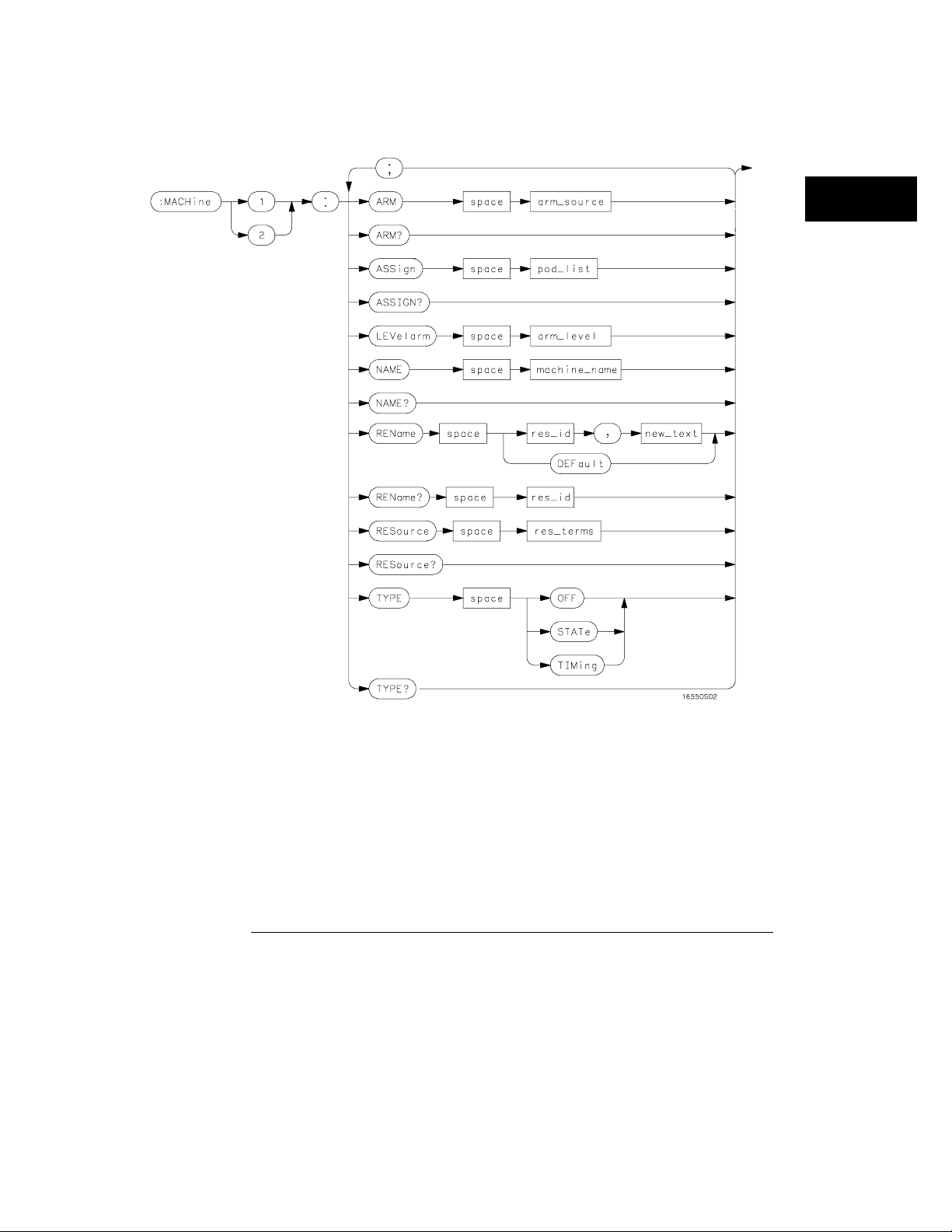
Figure 3-1
MACHine Subsystem
Machine Subsystem Syntax Diagram
3–3

MACHine Subsystem
MACHine
Table 3-1 Machine Subsystem Parameter Values
Parameter Value
arm_source {RUN | INTermodule | MACHine {1|2}}
pod_list {NONE | <pod_num>[, <pod_num>]...}
pod_num {1 | 2 | 3 | 4 | 5 | 6 | 7 | 8 | 9 | 10 | 11
| 12}
arm_level integer f rom 1 to 11 representing sequence level
machine_name string of up to 10 alphanumeric characters
res_id <state_terms> for state analyzer
or
{<state_terms>|GLEDge{1|2}} for timing analyzer
new_text string of up t o 8 alphanumeric characters
state_terms {A|B|C|D|E|F|G|H|I|J|RANGE{1|2}|TIMER{1|2}}
res_terms {<res_id>[,<res_id>]...}
MACHine
Selector :MACHine<N>
The MACHine <N> selector specifies which of the two analyzers (machines)
available in the HP 16550A the commands or queries following will refer to.
Because th e MAC Hine<N> command is a root le vel command , it will
norma lly appear as the first element of a com pound hea der.
<N> {1|2} (the machine number)
Example OUTPUT XXX; ":MACHINE1:NAME ’TIMING’"
3–4

ARM
Command :MACHine{1|2}:ARM <arm_source>
The ARM command specifies the arming source of the specified analyzer
(machine). The RU N o ption disables the arm source. For example, if you
do not want to use either the int ermodule bus o r the other m achine to arm
the current machine, you specify the RUN option.
<arm_source> {RUN|INTermodule|MACHine{1|2}}
Example OUTPUT XXX;":MACHINE1:ARM MACHINE2"
Query :MACHine{1|2}:ARM?
MACHine Subsystem
ARM
The ARM query r etu rns the so urce that the current analyze r (m achi ne) wil
be a rmed by.
Returned Format
Example OUTPUT XXX;":MACHINE:ARM?"
[:MACHine{1|2}:ARM] <arm_source>
3–5

MACHine Subsystem
ASSign
ASSi gn
Command :MACHine{1|2}:ASSign <pod_list>
The ASSign command as signs pods to a pa rticular a nalyzer (machine). The
AS Sign comma nd will assign two pods for each pod number you specify
because pods must be assigned to analyzers in pairs.
<pod_list> {NONE | <pod ># [, <po d ># ].. . }
<pod># {1|2|3|4|5|6|7|8|9|10|11|12}
Example OUTPUT XXX;":MACHINE1:ASSIGN 5, 2, 1"
Query :MACHine{1|2}:ASSign?
The ASSign query returns which pods are assigned to the current analyzer
(machine).
Returned Format
Example OUTPUT XXX;":MACHINE1:ASSIGN?"
[:MACHine{1|2}:ASSign] <pod_list><NL>
3–6

LEVelarm
Command :MACHine{1|2}:LEVelarm <arm_level>
The LEVelarm c omma nd allows you to specify the s eq uence leve l for a
specified machine that will be armed by the Intermodule Bus or the other
mach ine. This comm and is only valid if the specified machine is on and the
arm ing source is not set to RUN wi th the ARM c ommand.
<arm_level> integer from 1 to 11 representing sequence level
Example OUTPUT XXX;":MACHINE1:LEVELARM 2"
Query :MACHine{1|2}:LEVelarm?
MACHine Subsystem
LEVelarm
The LEVelarm query returns the current sequence level receiving the arming
fo r a specified m ach ine.
Returned Format
Example OUTPUT XXX;":MACHINE1:LEVELARM?"
[:MACHine{1|2}:LEVelarm] <arm_level><NL>
3–7

MACHine Subsystem
NAME
NAME
Command :MACHine{1|2}:NAME <machine_name>
The NAME command allows you to assign a name o f up to 10 charac ters to a
particula r analyzer (machine) for easier identification.
<machine_name> string of up to 10 alphanumeric characters
Example OUTPUT XXX;":MACHINE1:NAME ’DRAMTEST’"
Query :MACHine{1|2}:NAME?
The NAME query returns the current analyzer name as an AS CII string.
Returned Format [:MACHine{1|2}:NAME] <machine name><NL>
Example OUTPUT XXX;":MACHINE1:NAME?"
REName
Command :MACHine{1|2}:REName {<res_id>, <new_text> |
DEFault}
The R EName command allows you to as sign a specific name of up to eight
characters to terms A through J, Range 1 and 2, and T imer 1 and 2 in the
state analyzer. In the timing analyzer, GLEDge ( glitch/edge) 1 and 2 can be
renam ed in ad diti on to the terms av ail able in the state analyze r. The
DEFault option sets all r esource term name s to the defaul t names assigne d
when turning on th e instrume nt.
3–8

<res_id> <state_terms> for state analyzer
or
{<state_terms>|GLEDge{1|2}} for timing analyzer
<new_text> string of up to 8 alphanumeric characters
Example OUTPUT XXX;":MACHINE1:RENAME A,’DATA’"
Query :MACHine{1|2}:RENAME? <res_id>
The REName query returns the current names for specified terms assigned
to the spec ified an alyze r.
Returned Format
Example OUTPUT XXX;":MACHINE1:RENAME? D"
[:MACHine{1|2}:RENAME] <res_id>,<new_text><NL>
MACHine Subsystem
RESource
RESource
Command :MACHine{1|2}:RESource <res_terms>
The RESource command allows you to as sign resource terms A through J,
Range 1 and 2, and Timer 1 and 2 to a particular ana lyzer (machine 1 or 2).
In th e timing analy zer onl y, two ad ditional resource terms are available.
These terms are GLEDg e (G litch/Edge ) 1 and 2. These terms will alwa ys be
assigned to the the machi ne that is c onfigur ed as the tim ing analyze r.
<res_terms> {A|B|C|D|E|F|G|H|I|J|TIMer1|TIMer2|RANGe1|RANGe2}
Example OUTPUT XXX;":MACHINE1:RESOURCE A,C,RANGE1"
3–9

MACHine Subsystem
TYPE
Query :MACHine{1|2}:RESOURCE?
The RESour ce query returns the curren t re sour ce terms assigne d to the
specified analyzer.
Returned Format
Example OUTPUT XXX;":MACHINE1:RESOURCE?"
[:MACHine{1|2}:RESOURCE] <res_terms>[,<res_terms>,...]<NL>
TYPE
Command :MACHine{1|2}:TYPE <analyzer type>
The TYPE command specifies what type a s pecifie d analyz er (machine) will
be. The analyzer types are state or timing. The TYPE command also allows
you to turn off a particular machine.
Only one timing analyzer can be specified at a time.
<analyzer
type>
Example OUTPUT XXX;":MACHINE1:TYPE STATE"
Query :MACHine{1|2}:TYPE?
Returned Format
Example OUTPUT XXX;":MACHINE1:TYPE?"
{OFF|STATe|TIMing}
The TY PE query returns the current analyzer type for the specified analyzer.
[:MACHine{1|2}:TYPE] <analyzer type><NL>
3–10

Part 2
33 MAC Hine Subsystem 3-1
44 WLISt Subsyst em 4-1
55 S F OR mat Su b system 5-1
66 STRigger (STRace) Subsystem 6-1
77 SLISt Subsyst em 7-1
88 S WAVeform Subsystem 8-1
99 SCHart Su bsystem 9-1
1010 C OMPa re Subsystem 10-1
1111 TFORm at Su bsyste m 11-1
1212 TTRigger ( TTRace) Subsystem 12-1
1313 TWAVeform Subs ys tem 13-1
1414 T LISt Subsystem 14-1
1515 SYMBol Subsyst em 15-1
1616 DATA and SETup Command s 16-1
C ommands

4
W LISt Subs yste m
4–1

Introduction
The commands in the WLISt (Waveforms/LISting) subsystem control
the X and O marker placement on the waveforms portion of the
Timing/S tate mixed mode display. The XSTate and OSTate queries
return what states the X and O markers are on. Because the markers
ca n o nly be placed on the timing waveforms , the queries return wha t
state (state ac qu isition me mor y loc ation ) the m arked patte r n is
stored in.
In order to ha v e mixed mo de, one machine must be a state a nalyzer
with time taggin g on (use MACHine<N>:STRigger:TAG TIME).
• DELay
• INSert
• LINE
• MINus
• OSTate
• OTIMe
• OVERlay
• PLUS
• RANGe
• REMove
• XOT ime
• XSTate
• XTI Me
4–2

Figure 4-1
WLISt Subsystem
WLISt Subsystem Syntax Diagr am
4–3

WLISt Subsystem
WLISt
Table 4-1 WLISt Subsystem Parameter Values
Parameter Value
delay_value real number between -2500 s and +2500 s
module_spec {1|2|3|4|5|6|7|8|9|10} (slot where time card is
bit_id integer from 0 to 31
label_name string of up to 6 alphanumeric characters
line_num_mid_screen integer from -8191 to +8191
waveform string containing <acquisition_spec>{1|2}
time_value real number
time_range real number between 10 ns and 10 ks
WLISt
Selector :WLISt
The WLISt ( Waveforms/LISting) select or is used as a part of a compound
header to a c c ess the settings normally found in the Mixed Mo d e menu.
Because the W L I St comm and is a root level command, it w ill always appear
a s the first element of a compound header.
The WLISt subsystem is only ava ilable when one or more state analyzers
with time tagging on are specifi ed.
installed
Example OUTPUT XXX;":WLIST:XTIME 40.0E− 6"
4–4

DELay
Command :MACHine{1|2}:WLISt:DELay <delay_value>
The DELay command sp ec ifies the amount of time b etw een the timing
trigger and the horizontal center of the the timing waveform display. The
allowable values for delay are − 2500 s to +2500 s. If the acquisition mode is
automa tic , then in glitch acquisitio n mode, as de lay b ecomes large in an
absolute sense, the sample rate is adjusted so that data will be acquired in
the time windo w of interest. In transitional acqui sition mode, data may not
fall in the time wi ndow since th e sam ple period is fixe d and the amount of
time cov ered in mem ory is dependent on how freque nt the input signal
transiti ons o ccur.
<delay_value> real nu mber between − 2500 s and +2500 s
Example OUTPUT XXX;":MACHINE1:WLIST:DELAY 100E− 6"
WLISt Subsystem
DELay
Query :MACHine{1|2}:WLISt:DELay?
The DELay query returns the current time offset (delay) value from the
trigger.
Returned Format
Example OUTPUT XXX;":MACHINE1:WLIST:DELAY?"
[:MACHine{1|2}:WLISt:DELay] <time_value><NL>
4–5

WLISt Subsystem
INSert
INSert
Command :MACHine{1|2}:WLISt:INSert
[<module_spec>,]<label_name>
[,{<bit_id>|OVERlay|ALL}]
The INS ert command inserts waveforms in the timing wa v eform displa y.
The waveforms are added f rom top to bottom up to a maximum of 96
wave forms. Once 96 waveforms are pres ent, each time you insert another
waveform, it replac es the las t waveform.
Time- correlated wav efo rms f rom the oscilloscope and high speed timing
modules can also be inserted in the logic analyzer’s timing waveforms
display. Os cillosco pe wa vef orms o ccupy the same displa y space as three
lo gic analyzer wavef orms. When inserting waveforms from the oscilloscope
or high-spe ed timing modules, the optiona l first para meter must be used,
which is the modu le specifier. 1 through 10 corresponds to modules A
thro ug h J. If you do not specify the modu le , the se lected module is assumed.
The seco nd parame ter s pecifie s the label name that will be ins erted. The
optional third parameter specifies the label bit number, overlay, or all. If a
numbe r is sp ec ified, onl y the waveform for that bit num ber is added to the
screen.
If you specify O VERlay, all the bits of the la be l are displa yed as a compo site
o ve rlaid waveform. If you specify AL L, all the b its are displayed
sequenti all y. If yo u do not specify the third param eter, ALL is assu me d.
<module_spec> {1|2|3|4|5|6|7|8|9|10}
<label_name> string of up to 6 alphanumeric characters
<bit_id> integer from 0 to 31
Example OUTPUT XXX;":MACHINE1:WLIST:INSERT 3, ’WAVE’,10"
4–6

Inserting Oscilloscope WaveformsInserting Oscilloscope Waveforms
Command :MACHine{1|2}:WLISt:INSert
<module_spec>,<label_name>
This inse rts a waveform from a n oscillos cope to the timing wave forms
display.
<module_spec> {1|2|3|4|5|6|7|8|9|10} slot in which timebase card is installed
<label_name> string of one alpha and one numeric character
Example OUTPUT XXX;":MACHINE1:WLIST:INSERT 5, ’C1’"
LINE
WLISt Subsystem
LINE
Command :MACHine{1|2}:WLISt:LINE <line_num_mid_screen>
The LINE com mand allows you to scro ll th e timin g analyzer listing vertically.
The command specifies the state line number relative to the trigger that the
analyzer highlights at the center of the screen.
<line_num_mid_
screen>
Example OUTPUT XXX;":MACHINE1:WLIST:LINE 0"
integer from − 8191 to +8191
4–7

WLISt Subsystem
MINus
Query :MACHine{1|2}:WLISt:LINE?
The LINE query returns the line number for the state currently in the box at
center screen.
Returned Format
Example OUTPUT XXX;":MACHINE1:WLIST:LINE?"
[:MACHine{1|2}:WLISt:LINE] <line_num_mid_screen><NL>
MINus
Command :WLISt:MINus <module_spec>,<waveform>,<waveform>
The MINus command inserts time-correlated A− B (A minus B) o scilloscope
waveforms on the s cre en. The first parameter is the module specifi er where
the oscillosco pe module resides, where 1 through 10 refers to slots A
through J. The next two param eters specify which waveforms will be
subtracted from ea ch other.
MINu s is only available fo r os cillosco pe wa ve forms.
<module_spec> {1|2|3|4|5|6|7|8|9|10}
<waveform> string containing <acquisition_spec>{1|2}
<acquisition_
spec>
Example OUTPUT XXX; ":WLIST:MINUS 2,’A1’,’A2’"
{A|B|C|D|E|F|G|H|I|J} (slot where acquisition card is located)
4–8

OS Tate
Query :WLISt:OSTate?
The OST ate query r etu r ns the state where the O Marker is p osition ed. If
data is not valid, the query returns 32767.
Returned Format
<state_num> integer
Example OUTPUT XXX;":WLIST:OSTATE?"
[:WLISt:OSTate] <state_num><NL>
OTIMe
WLISt Subsystem
OSTate
Command :WLISt:OTIMe <time_value>
The OTIMe command p ositions the O Mark er on the timing waveforms in the
mixed mode display. If the da ta is not va lid, the command performs no
act ion.
<time_value> rea l number
Example OUTPUT XXX;":WLIST:OTIME 40.0E− 6"
4–9

WLISt Subsystem
OVERlay
Query :WLISt:OTIMe?
The OTIMe que ry retur ns the O Marke r positi on i n time. If data is not valid,
the query returns 9.9E37.
Returned Format
Example OUTPUT XXX;":WLIST:OTIME?"
[:WLISt:OTIMe] <time_value><NL>
OVERlay
Command :MACHine{1|2}:WLISt:OVERlay <module_number>,
<label>[, <label>]...
The OVE Rla y c ommand overla ys tw o or more oscilloscope waveforms and
adds the res ultant waveform to the current wave form display. The first
parameter of the command syntax specifies which slot contains the
o scilloscope time b as e card. The ne x t p ara meters are the labels of the
waveforms that are to be ove rlaid.
<module_spec> {1|2|3|4|5|6|7|8|9|10}
<waveform> string containing <acquisition_spec>{1|2}
<acquisition_
spec>
Example OUTPUT XXX;":MACHINE1:WLIST:OVERLAY 4, ’C1’,’C2’"
{A|B|C|D|E|F|G|H|I|J} (slot where acquisition card is located)
4–10

WLISt Subsystem
PLUS
Command :WLISt:PLUS <module_spec>,<waveform>,<waveform>
The PLUS command ins erts time- correlate d A+B oscillos cope wave forms on
the scree n. The first para me ter is the modu le spe cifier where the
o scilloscope mod ule resides, where 1 throug h 10 refers to slots A through J.
The next two parame ters spe cify which wave forms will be s ubtracted from
ea ch other.
PLUS is only available for os cillosco pe wa ve forms.
<module_spec> {1|2|3|4|5|6|7|8|9|10}
<waveform> string containing <acquisition_spec>{1|2}
PLUS
<acquisition_
spec>
Example OUTPUT XXX; ":WLIST:PLUS 2,’A1’,’A2’"
{A|B|C|D|E|F|G|H|I|J} (slot where acquisition card is located)
4–11

WLISt Subsystem
RANGe
RANGe
Command :MACHine{1|2}:WLISt:RANGe <time_value>
The RANGe command spe cifies the full-screen time in the timing waveform
menu. It is equi valent to ten ti me s the sec onds p er division setting on the
display. The allowable va lues for RANGe are from 10 ns to 10 ks.
<time_range> real number between 10 ns and 10 ks
Example OUTPUT XXX;":MACHINE1:WLIST:RANGE 100E− 9"
Query :MACHine{1|2}:WLISt:RANGe?
The RANGe query returns the current full-screen time.
Returned Format [:MACHine{1|2}:WLISt:RANGe] <time_value><NL>
Example OUTPUT XXX;":MACHINE1:WLIST:RANGE?"
REMove
Command :MACHine{1|2}:WLISt:REMove
The R EM o ve command de letes all waveforms from the display.
Example OUTPUT XXX;":MACHINE1:WLIST:REMOVE"
4–12

XOTime
Query :MACHine{1|2}:WLISt:XOTime?
The X OTim e q ue ry retur ns the time from the X marker to the O marke r. I f
data is not valid, the query re turns 9 .9E37.
Returned Format
<time_value> rea l number
Example OUTPUT XXX;":MACHINE1:WLIST:XOTIME?"
[:MACHine{1|2}:WLISt:XOTime] <time_value><NL>
XSTate
WLISt Subsystem
XOTime
Query :WLISt:XSTate?
The X STate q uery retur ns the state w here the X Marker is p osition ed. If
data is not valid, the query returns 32767.
Returned Format
<state_num> integer
Example OUTPUT XXX;":WLIST:XSTATE?"
[:WLISt:XSTate] <state_num><NL>
4–13

WLISt Subsystem
XTIMe
XTIMe
Command :WLISt:XTIMe <time_value>
The X TIMe command positions the X Marker on the timing waveforms in the
mixed mode display. If the da ta is not va lid, the command performs no
act ion.
<time_value> rea l number
Example OUTPUT XXX;":WLIST:XTIME 40.0E− 6"
Query :WLISt:XTIMe?
The X TIMe query re turns th e X Marker position in time. If data is not valid,
the query returns 9.9E37.
Returned Format
[:WLISt:XTIMe] <time_value><NL>
Example OUTPUT XXX;":WLIST:XTIME?"
4–14

5
SFORmat Subsystem
5–1

Introduction
The SFORmat subs ystem c o ntains the commands availa ble for the
State Format menu in the HP 16550A logic analyzer module. These
commands are:
• CLOCk
• LABel
• MAS Ter
• MODE
• MOPQual
• MQUal
• REMove
• SETHold
• SLAVe
• SOPQual
• SQUal
• THReshol d
5–2

Figure 5-1
SFORmat Subsystem
SFORmat Subsystem Syntax Diagram
5–3

Figure 5-1 (continued)
SFORmat Subsystem
SFORmat Subsystem Syntax Diagram (continued)
5–4

Table 5-1 SFORmat Subsystem Parameter Values
Parameter Value
SFORmat Subsystem
<N> {{1 | 2 | 3 | 4 | 5 | 6}|{7 | 8 | 9 | 10 | 11
label_name string of up to 6 alphanumeric characters
polarity {POSitive | NEGative}
clock_bits format (integer from 0 to 63) for a clock (clocks are assigned in
upper_bits format (integer from 0 to 65535) for a pod (pods are assigned in
lower_bits format (integer from 0 to 65535) for a pod (pods are assigned in
clock_id {J | K | L | M | N | P}
clock_spec {OFF | RISing | FALLing | BOTH}
clock_pair_id {1 | 2}
qual_operation {AND|OR}
qual_num {1 | 2 | 3 | 4}
qual_level {OFF | LOW | HIGH}
pod_num {1 | 2| 3 | 4 | 5 | 6 | 7 | 8 | 9 | 10 | 11 |
| 12}}
decreasing order)
decreasing order)
decreasing order)
12}
set_hold_value {0 | 1 | 2 | 3 | 4 | 5 | 6 | 7 | 8 | 9}
value voltage (real number) -6.00 to +6.00
5–5

SFORmat Subsystem
SFORmat
SFORmat
Selector :MACHine{1|2}:SFORmat
The SFORmat ( State Format) select or is used as a part of a compound
he ade r to access the setting s in the State Format me nu . It alw ays follows
the MACHine se lector beca use it selects a branch directly below the
M AC Hine leve l in th e comm and tree.
Example OUTPUT XXX;":MACHINE2:SFORMAT:MASTER J, RISING"
CLOCk
Command :MACHine{1|2}:SFORmat:CLOCk<N> <clock_mode>
The CLOCk command s elects the clocking mode for a g iven pod when the
pod is ass igned to the state analyzer. When the MASTer option is specified,
the po d will sample all 16 channels on the master clock. When the SLAVe
o ption is specified, th e pod w ill sample all 16 channels o n the sla ve
clock. When the DEMultiplex option is s pecified, only one pod of a pod pair
can acquire data. The 16 bits of the selected pod will be clocked by the
demultiplex ma ster for la b els with bits assigne d unde r the Master pod. The
same 16 bits will be clocked by the demultiplex slave for labels with bits
a ssigned unde r the Slav e pod. The master clock always follows the sla v e
clock when both are used.
<N> {{1|2|3|4|5|6}| { 7|8| 9| 10| 11| 12} } 1 through 6 for one card or 1 through 12 for a
two-card set
<clock_mode> {MASTer | SLAVe | DEMultiplex}
Example OUTPUT XXX;":MACHINE1:SFORMAT:CLOCK2 MASTER"
5–6

Query :MACHine{1|2}:SFORmat:CLOCk<N>?
The CLOCk query returns the current clocking mode for a given pod.
Returned Format [:MACHine{1|2}:SFORmat:CLOCK<N>] <clock_mode><NL>
Example OUTPUT XXX; ":MACHINE1:SFORMAT:CLOCK2?"
LABel
Command :MACHine{1|2}:SFORmat:LABel
<name>,[<polarity>,<clock_bits>, <upper_bits>,
<lower_bits>[,<upper_bits>,<lower_bits>]...]
Th e LABe l command allows you to spe cify p ola rity and ass ign chann els to
new or ex isting labels . If the specifie d la be l na me does not m atch a n
exis tin g label name, a new label will be created.
The order of the pod-specification parame ters is significa nt. The first one
li sted wil l match the hi gh est numbered pod assigned to the machine you’re
using. Each pod specific atio n a fter that is ass igned to th e next highes t
numbered pod. This way they match the left-to-right desce nding order of
the pods you see on the Format display. No t including enough pod
specifications results in the lowest nu mbered pod(s) being assigned a value
o f zero (all channels exclu ded). If you in clud e more pod specifications than
there are pods for that machine, the extra one s will be ignored. Howe v er, an
erro r is reported a nytime wh en more than 1 3 pod specifications a re listed.
The polarity ca n be spe cified at any point afte r the label name.
Because pods contain 16 channels, the format value for a pod must be
between 0 and 65535 (2
(b ase 2), each bit will correspon d to a s ingle c ha nnel. A "1" in a bit pos ition
means the associated channel in that pod is assigned to that pod and bit. A
"0" in a bit position means the associated channel in that pod is excluded
from the label. For example, as signing #B1111001100 is equivalent to
entering "......****..**.." thr ou gh the touchsc r ee n.
A lab el can not have a total of more than 32 channels assigned to it.
16
− 1). When g iving the pod assignment in binary
SFORmat Subsystem
LABel
5–7

SFORmat Subsystem
LABel
<name> string of up to 6 alphanumeric characters
<polarity> {POSitive | NEGative}
<clock_bits> format ( integer from 0 to 63) for a clock ( clocks are assigned in decreasing
order)
<upper_bits> format ( integer from 0 to 65535) for a pod (pods a re assigned in decreasing
order)
<lower_bits> format ( integer from 0 to 65535) for a pod (pods a re assigned in decreasing
order)
Examples OUTPUT XXX;":MACHINE2:SFORMAT:LABEL ’STAT’, POSITIVE,
0,127,40312"
OUTPUT XXX;":MACHINE2:SFORMAT:LABEL ’SIG 1’,
#B11,#B0000000011111111,
#B0000000000000000 "
Query :MACHine{1|2}:SFORmat:LABel? <name>
The LABel query re turns th e current specific ation for the selected (by
name) la be l. If the labe l does not exist, nothin g is returned. The polarity is
always re tu rne d as the fi rst parameter. Numbers a re a lways re tu rne d in
decimal format.
Returned Format
[:MACHine{1|2}:SFORmat:LABel] <name>,<polarity>
[, <assignment>]...<NL>
Example OUTPUT XXX;":MACHINE2:SFORMAT:LABEL? ’DATA’"
5–8

MASTer
Command :MACHine{1|2}:SFORmat:MASTer
<clock_id>,<clock_spec>
The MAS Ter clock command allows you to specify a master clock for a given
machine. The mas ter clock is used in all clocking modes (Master, Slave , and
Demultiplexed). Each command deals with only one clock (J,K,L,M,N,P);
therefore, a complete clock specification requires six commands, one for
ea ch c lock. Ed ge specifications (RISing, FALLing, or BOTH) are O Red.
At lea st one clock edge must be specified.
<clock_id> {J|K|L|M|N|P}
<clock_spec> {OFF|RISing|FALLing|BOTH}
Example OUTPUT XXX;":MACHINE2:SFORMAT:MASTER J, RISING"
SFORmat Subsystem
MASTer
Query :MACHine{1|2}:SFORmat:MASTer? <clock_id>
The MASTer query returns the clock specification for the specified clock.
Returned Format
Example OUTPUT XXX;":MACHINE2:SFORMAT:MASTER? <clock_id>"
[:MACHine{1|2}:SFORmat:MASTer] <clock_id>,<clock_spec><NL>
5–9

SFORmat Subsystem
MODE
MODE
Command :MACHine{1|2}:SFORmat:MODE <acq_mode>
The MODE command allows you to select the ac qui stion mode of the state
analyzer. The modes are either full-channe l with 4 Kbit of memory depth
per channe l or half-channel with 8 Kbit of memory depth per channel.
<acq_mode> {FULL|DEEPmemory}
Example OUTPUT XXX;":MACHine1:SFORMAT:MODE FULL"
Query :MACHine{1|2}:SFORmat:MODE?
The MODE query returns th e c urrent acquistio n mode.
Returned Format [:MACHine{1|2}:SFORmat:MODE] <acq_mode><NL>
Example OUTPUT XXX;":MACHINE1:SFORMAT:MODE?"
MOPQual
Command :MACHine{1|2}:SFORmat:MOPQual
<clock_pair_id>,<qual_operation>
The MOPQual (master op eratio n qualifier) comma nd allows you to specify
either the AND or the OR operation between master clock qualifier pair 1
and 2, or between master clock qualifier pair 3 and 4. For example, you can
specify a master clock operation qualifer 1 AND 2.
5–10

SFORmat Subsystem
MQUal
<clock_pair_
id>
<qual_
operation>
Example OUTPUT XXX;":MACHINE1:SFORMAT:MOPQUAL 1,AND"
Query :MACHine{1|2}:SFORmat:MOPQUal? <clock_pair_id>
Returned Format
Example OUTPUT XXX;":MACHine1:SFORMAT:MOPQUAL? 1"
{1|2}
{AND|OR }
The MOPQual query returns the operation qu alifier specified fo r th e mas ter
clock.
[:MACHine{1|2}:SFORmat:MOPQUal <clock_pair_id>]
<qual_operation><NL>
MQUal
Command :MACHine{1|2}:SFORmat:MQUal
<qual_num>,<clock_id>,<qual_level>
The MQUal (master qualifier) comma nd allows you to specify the leve l
q ua lif ier fo r the mas ter clock.
<qual_num> {1|2|3|4}
<clock_id> {J|K|L|M|N|P}
<qual_level> {OFF| LOW | HIGH}
Example OUTPUT XXX;":MACHINE2:SFORMAT:MQUAL 1,J,LOW"
5–11

SFORmat Subsystem
REMove
Query :MACHine{1|2}:SFORmat:MQUal? <qual_num>
The MQUal query returns the qualifier specified for the master clock.
Returned Format [:MACHine{1|2}:SFORmat:MQUal] <qual_level><NL>
Example OUTPUT XXX;":MACHINE2:SFORMAT:MQUAL? 1"
REMove
Command :MACHine{1|2}:SFORmat:REMove {<name>|ALL}
The REMove command allows you to delete all labe ls or any one label for a
given machine.
<name> string of up to 6 alphanumeric characters
Examples OUTPUT XXX;":MACHINE2:SFORMAT:REMOVE ’A’"
OUTPUT XXX;":MACHINE2:SFORMAT:REMOVE ALL"
SETHold
Command :MACHine{1|2}:SFORmat:SETHold
<pod_num>,<set_hold_value>
The SETHold (se tup/hold) command allows yo u to set the setup and ho ld
specification fo r th e state ana lyzer.
Even though the command requires integers to specify the setup and hold,
the query returns the current set tings in a string. For example, if you send
the integer 0 for the setup and hold value, the query will return 3.5/0.0 ns as
an ASCII string when you have one clock and one edge specified.
5–12

SFORmat Subsystem
SETHold
<pod_num> {1|2|3|4|5|6} for a single board or {1|2|3|4|5|6|7|8|9|10|11|12} for a
pair of boards
<set_hold_
Table 5-2
value>
integer {0|1|2|3|4|5|6|7|8|9} representing the following setup and
hold v alues:
Setup and hold values
For one clock and one edge For one clock and both edges Multiple Clocks
0 = 3.5/0.0 ns 0 = 4.0/0.0 0 = 4.5/0.0
1 = 3.0/0.5 ns 1 = 3.5/0.5 1 = 4.0/0.5
2 = 2.5/1.0 ns 2 = 3.0/1.0 2 = 3.5/1.0
3 = 2.0/1.5 ns 3 = 2.5/1.5 3 = 3.0/1.5
4 = 1.5/2.0 ns 4 = 2.0/2.0 4 = 2.5/2.0
5 = 1.0/2.5 ns 5 = 1.5/2.5 5 = 2.0/2.5
6 = 0.5/3.0 ns 6 = 1.0/3.0 6 = 1.5/3.0
7 = 0.0/3.5 ns 7 = 0.5/3.5 7 = 1.0/3.5
N/A 8 = 0.0/4.0 8 = 0.5/4.0
N/A N/A 9 = 0.0/4.5
Example OUTPUT XXX;":MACHINE2:SFORMAT:SETHOLD 1,2"
Query :MACHine{1|2}:SFORMAT:SETHOLD? <pod_num>
T he SETHold query r etur ns th e current setup an d h old setting s.
Returned Format [:MACHine{1|2}:SFORmat:SETHold <pod_num>] <set_hold_value><NL>
Example OUTPUT XXX;":MACHINE2:SFORMAT:SETHOLD? 3"
5–13

SFORmat Subsystem
SLAVe
SLAVe
Command :MACHine{1|2}:SFORmat:SLAVe <clock_id>,<clock_spec>
The S LAVe clock command allows you to specify a slave clock for a given
m achine. T he slave clock is only use d in the Slave and Demu ltiplex ed
clocking modes. Each command deals with only one clock (J,K,L,M,N,P );
therefore, a complete clock specification requires six commands, one for
ea ch c lock. Ed ge specifications (RISing, FALLing, or BOTH) are O Red.
When slave clock is being used at least one edge must be specified.
<clock_id> {J|K|L|M|N|P}
<clock_spec> {OFF|RISing|FALLing|BOTH}
Example OUTPUT XXX;":MACHINE2:SFORMAT:SLAVE J, RISING"
Query :MACHine{1|2}:SFORmat:SLAVe?<clock_id>
The SLAVe query returns the clock specification for the specified clock.
Returned Format
Example OUTPUT XXX;":MACHINE2:SFORMAT:SLAVE? K"
[:MACHine{1|2}:SFORmat:SLAVe] <clock_id>,<clock_spec><NL>
5–14

SOPQual
Command :MACHine{1|2}:SFORmat:SOPQual
<clock_pair_id>,<qual_operation>
The SOPQual (slave operation qu alifier) comm and allow s yo u to specify
either the AND or the O R operation between slave clock qualifier pair 1 and
2, or between slave clock qualifier pair 3 and 4. For example you can specify
a slave clock operation qualifer 1 AND 2.
SFORmat Subsystem
SOPQual
<clock_pair_
id>
<qual_
operation>
Example OUTPUT XXX;":MACHine2:SFORMAT:SOPQUAL 1,AND"
Query :MACHine{1|2}:SFORmat:SOPQual? <clock_pair_id>
Returned Format
Example OUTPUT XXX;":MACHiNE2:SFORMAT:SOPQUAL? 1"
{1|2}
{AND|OR }
The SOPQual query returns the operation qualifier specifie d for the slave
clock.
[:MACHine{1|2}:SFORmat:SOPQual <clock_pair_id>]
<qual_operation><NL>
5–15

SFORmat Subsystem
SQUal
SQUal
Command :MACHine{1|2}:SFORmat:SQUal
<qual_num>,<clock_id>,<qual_level>
The SQUal (slave qualifier) co mmand allows you to specify th e level qu alifier
for the s lave clock.
<qual_num> {1|2|3|4}
<clock_id> {J|K|L|M|N|P}
<qual_level> {OFF| LOW | HIG H}
Example OUTPUT XXX;":MACHINE2:SFORMAT:SQUAL 1,J,LOW"
Query :MACHine{1|2}:SFORmat:SQUal?<qual_num>
The SQUal query returns the qualifier specified for the sla ve clock.
Returned Format
Example OUTPUT XXX;":MACHINE2:SFORMAT:SQUAL? 1"
[:MACHine{1|2}:SFORmat:SQUal] <clock_id>,<qual_level><NL>
THReshold
Command :MACHine{1|2}:SFORmat:THReshold<N>
{TTL|ECL|<value>}
The THRes hold command allows you to set the voltag e thres hold for a g iven
pod to ECL, TTL, or a s pecific voltag e from − 6.00 V to +6.00 V in 0.05 volt
increments.
5–16

<N> pod number {1|2|3|4|5|6|7|8|9|10|11|12}
<value> voltage (real number) − 6.00 to +6.00
TTL default value of +1.6 V
ECL default value of − 1.3 V
Example OUTPUT XXX;":MACHINE1:SFORMAT:THRESHOLD1 4.0"
Query :MACHine{1|2}:SFORmat:THReshold<N>?
The THRes hold query returns the current threshold for a given pod.
Returned Format
[:MACHine{1|2}:SFORmat:THReshold<N>] <value><NL>
Example OUTPUT XXX;":MACHINE1:SFORMAT:THRESHOLD4?"
SFORmat Subsystem
THReshold
5–17

5–18

6
STRigger (S TRace) Subsyst em
6–1

Introduction
The STRigger subsystem contains the commands available for the
S tate Trigger menu in the HP 16550A logic ana lyzer module. The
S tate Trigger subsystem will also accept the STRace selector as used
in previous HP 16500-Series Logic Analyzer modules to eliminate the
need to rewrite prog rams containing STRace as the s elector keyword.
The STRigger subsystem commands are:
• ACQuisition
• BRANch
• CLEar
• FIND
• RANGe
• SEQuence
• STORe
• TAG
• TAKenbranch
• TCONtr ol
• TERM
• TIMER
• TPOSit ion
6–2

Figure 6-1
STRigger (STRace) Subsystem
STRigger Subsystem Syntax Diagram
6–3

Figure 6-1 (continued)
STRigger (STRace) Subsystem
STRigger Subsystem Syntax Diagram (continued)
6–4

Figure 6-1 (continued)
STRigger (STRace) Subsystem
STRigger Subsystem Syntax Diagram (continued)
6–5

STRigger (STRace) Subsystem
Table 6-1 STRigger Subsystem Parameter Values
Parameter Value
branch_qualifier <qualifier>
to_lev_num integer from 1 to last level
proceed_qualifier <qualifier>
occurrence number from 1 to 1048575
label_name string of up to 6 alphanumeric characters
start_pattern "{#B{0|1} . . . |
#Q{0|1|2|3|4|5|6|7} . . . |
#H{0|1|2|3|4|5|6|7|8|9|A|B|C|D|E|F} . . . |
{0|1|2|3|4|5|6|7|8|9} . . . } "
stop_pattern "{#B{0|1} . . . |
#Q{0|1|2|3|4|5|6|7} . . . |
#H{0|1|2|3|4|5|6|7|8|9|A|B|C|D|E|F} . . . |
{0|1|2|3|4|5|6|7|8|9} . . . }"
num_of_levels integer from 2 to 12
lev_of_trig integer from 1 to (number of existing sequence levels - 1)
store_qualifier <qualifier>
state_tag_qualifier <qualifier>
timer_num {1|2}
timer_value 400 ns to 500 seconds
term_id {A|B|C|D|E|F|G|H|I|J}
pattern "{#B{0|1|X} . . . |
#Q{0|1|2|3|4|5|6|7|X} . . . |
#H{0|1|2|3|4|5|6|7|8|9|A|B|C|D|E|F|X} . . .
|
{0|1|2|3|4|5|6|7|8|9} . . . }"
qualifier see "Qualifier" on page 6-5
post_value integer from 0 to 100 representing percentage
6–6

STRigger (STRace) Subsystem
Qualifier
Qualifier
The qualifier for the state trigger subsystem can be terms A through J,
Timer 1 and 2, and Range 1 and 2. In addition, qualifiers can be the NOT
boolea n function of terms, timers, and range s. The qualifier can also be an
expression or combination of expressions as shown below and figure 6-2,
"Complex Qualifier," on page 6-11.
Th e fo llowin g parameters sho w how qualifiers are specifie d in a ll command s
of the STRigger subsystem that use <qualifier>.
<qualifier>
{ "ANYSTATE" | "NOSTATE" | "<expression>" }
<expression> {<expression1a>|<expression1b>|<expression1a> OR
<expression1b>|<expression1a> AND <expression1b>}
<expression1a> {<expression1a_term>|(<expression1a_term>[ OR
<expression1a_term>]* )|(<expression1a_term>[ AND
<expression1a_term>]* )}
<expression1a_
{ <expression2a>|<expression2b>|<expression2c>|<expression2d>}
term>
<expression1b> {<expression1b_term>|( <expression1b_term>[ OR
<expression1b_term>]* )|(<expression1b_term>[ AND
<expression1b_term>]* )}
<expression1b_
{<expression2e>|<expression2f>|<expression2g>|<expression2h>}
term>
<expression2a> {<term3a>|<term3b>|(<term3a> <boolean_op> <term3b>)}
<expression2b> {<term3c>|<range3a>|(<term3c> <boolean_op> <range3a>)}
<expression2c> {<term3d>}
<expression2d> {<term3e>|<timer3a>|(<term3e> <boolean_op> <timer3a>)}
<expression2e> {<term3f>|<term3g>|(<term3f> <boolean_op> <term3g>)}
<expression2f> {<term3h>|<range3b>|(<term3h> <boolean_op> <range3b>)}
<expression2g> {<term3i>}
<expression2h> {<term3j>|<timer3b>|(<term3e> <boolean_op> <timer3b>)}
<boolean_op> {AND | NAND | OR | NOR | XOR | NXOR}
<term3a> { A | NOTA }
6–7

STRigger (STRace) Subsystem
Qualifier
<term3b> { B | NOTB }
<term3c> { C | NOTC }
<term3d> { D | NOTD }
<term3e> { E | NOTE }
<term3f> { F | NOTF }
<term3g> { G | NOTG }
<term3h> { H | NOTH }
<term3i> { I | NOTI }
<term3j> { J | NOTJ }
<range3a> { IN_RANGE1 | OUT_RANGE1 }
<range3b> { IN_RANGE2 | OUT_RANGE2 }
<timer3a> { TIMER1< | TIMER1>}
<timer3b> { TIMER2< | TIMER2>}
Qualifier RulesQualifier Rules
The following rules a pply to qualifiers:
•
•
•
•
Examples ’A’
’( A OR B )’
’(( A OR B ) AND C )’
’(( A OR B ) AND C AND IN_RANGE2 )’
’(( A OR B ) AND ( C AND IN_RANGE1 ))’
’IN_RANGE1 AND ( A OR B ) AND C’
6–8
Qualifiers are quoted strings and, therefore, need quotes.
Expressions are evaluated from left to right.
Parenthesis are used to change the order evaluation and, therefore, are
option al.
An exp ression m us t map into th e combinatio n logic p resen ted in th e
com b ina tion pop-up me nu within the STRigger menu (see figure 6-2 on
page 6-11).

S TRigger (S TRace)
Selector :MACHine{1|2}:STRigger
The STRigger ( STRace) ( State Trigger) selector is used as a part of a
comp o und header to ac c ess the settings found in the State Trac e menu. It
always fo llows the MA CHine se lector because it selects a branch directly
b elo w th e M ACHine leve l in th e comma n d tre e.
Example OUTPUT XXX;":MACHINE1:STRIGGER:TAG TIME"
ACQuisition
Command :MACHine{1|2}:STRigger:ACQuisition
{AUTOmatic|MANual}
STRigger (STRace) Subsystem
STRigger (STRace)
The A CQ uis ition comma nd allows you to specify the a cquisition mode for
the State analyzer.
Example OUTPUT XXX;":MACHINE1:STRIGGER:ACQUISITION AUTOMATIC"
Query :MACHine{1|2}:STRigger:ACQuisition?
The A CQ uis ition query return s the current a cquisition mode spe cified.
Returned Format
Example OUTPUT XXX;":MACHINE1:STRIGGER:ACQUISITION?"
[:MACHine{1|2}:STRigger:ACQuisition] {AUTOmatic|MANual}<NL>
6–9

STRigger (STRace) Subsystem
BRANch
BRANch
Command :MACHine{1|2}:STRigger:BRANch<N>
<branch_qualifier>,<to_level_number>
The BRANch command defines the branch qualifier for a given se q ue nce
level. When this branch qualifier is matched , it will cause th e sequencer
to ju mp to the s pecifie d sequence level.
The terms used by the branch qualifier (A through J) are defined by the
TERM command. The meaning of IN_RANGE and OUT_RANGE is
determined by the RANG E command.
With in the limitations shown by the syntax definitions, compl ex expressions
may be formed using the AND and OR operators. Express ions are limited to
what you could manually enter through the State Trigger menu. Regarding
parentheses, the syntax definitions o n the next page show only the required
one s. Additional parenthes es are a llowed as long as the meaning o f the
expression is not changed. Figure 6-2 shows a complex expression as seen
in the State Trigger menu.
Example The following stat ements are all correct and have the same meaning. Notice
that the conventional rules for precedence are not followed. The
expressions are evaluated from left to right.
OUTPUT XXX;":MACHINE1:TTRIGGER:BRANCH1 ’C AND D OR F OR G’, 1"
OUTPUT XXX;":MACHINE1:TTRIGGER:BRANCH1 ’((C AND D) OR (F OR
G))’, 1"
OUTPUT XXX;":MACHINE1:TTRIGGER:BRANCH1 ’F OR (C AND D) OR G’,1"
<N> integer from 1 to <number_of_levels>
<to_level_
number>
<number_of_
levels>
<branch_
qualifier>
integer from 1 to <number_of_levels>
integer from 2 to the number of existing sequence levels (maximum 12)
<qualifie r> see "Qualifier" o n page 5
6–10

STRigger (STRace) Subsystem
Examples OUTPUT XXX;":MACHINE1:STRIGGER:BRANCH1 ’ANYSTATE’, 3"
OUTPUT XXX;":MACHINE2:STRIGGER:BRANCH2 ’A’, 7"
OUTPUT XXX;":MACHINE1:STRIGGER:BRANCH3 ’((A OR B) OR NOTG)’, 1"
Query :MACHine{1|2}:STRigger:BRANch<N>?
Th e BRAN ch q uery returns the current branch qu alifier specification for a
given seque nce level.
Returned Format
[:MACHine{1|2}:STRigger:BRANch<N>]
<branch_qualifier>,<to_level_num><NL>
Example OUTPUT XXX;":MACHINE1:STRIGGER:BRANCH3?"
Figure 6-2
BRANch
Complex qualifier
Figure 6-2 is a front panel representation of the complex qualifier (a Or
b) And (g Or h).
6–11

STRigger (STRace) Subsystem
CLEar
Example The following exam ple would be us ed to specify this complex qualifier.
OUTPUT XXX;":MACHINE1:STRIGGER:BRANCH1 ’((A OR B) AND (G OR
H))’, 2"
Terms A through E, R ANGE 1, and TIMER 1 m ust be grouped toge ther
and terms F through J, RANGE 2, and TIMER 2 must be grouped
together. In the first lev el, term s fr om one g roup may no t be mi xed with
terms from the other. For example, the expression (( A OR IN_RANGE2)
AND (C OR H)) is not allowed becau se th e term C cannot be specified in th e
E through J group.
In th e fir st leve l, the ope r ators you can use are AND, NAND, OR, NOR,
XOR, NXOR. Either AND or OR may b e used at the second level to join the
two groups toge ther. It is acceptable for a gro up to consist of a sing le term.
Thus , an expres sion like (B AND G) is legal, since the two operands are
both simple terms from separate groups.
CLEar
Command :MACHine{1|2}:STRigger:CLEar
{All|SEQuence|RESource}
The CLEar command allows you to clear all settings in the State Trigger
menu and repl ace them with the defaul t, cl ear on ly the Sequence levels, or
c lea r only th e res ource term pa tterns.
Example OUTPUT XXX;":MACHINE1:STRIGGER:CLEAR RESOURCE"
6–12

FIND
Command :MACHine{1|2}:STRigger:FIND<N>
<proceed_qualifier>,<occurrence>
The FIND comma nd defines the proceed qualifier for a given se q ue nce level.
The qualifier tells the state analyz er when to pro ce ed to the next se quence
level. When this proceed qua lif ier is match ed the specified n umber of times,
the sequencer will proceed to the next sequence level. In the sequence level
where the trigger is specified, the FIND command specifies the trigger
q ua lif ier (see SEQuence c omma nd).
The terms A through J are defined by the TERM comm and. The me aning of
IN_RANGE a nd OUT_RANGE is determined by the RANGe command.
Expressions are lim ited to w ha t you c ould manually e nte r through the State
Trigger menu. Regarding parentheses, the syntax definitions below show
only the required on es. Additional parentheses are allowed as long as the
meaning of the expression is not changed. See figure 6-2 for a detailed
example.
STRigger (STRace) Subsystem
FIND
<N> integer from 1 to (number of existing sequence levels − 1)
<occurrence> integer from 1 to 1048575
<proceed_
qualifier>
Examples OUTPUT XXX;":MACHINE1:STRIGGER:FIND1 ’ANYSTATE’, 1"
<qualifie r> see "Qualifier" o n page 6-5
OUTPUT XXX;":MACHINE1:STRIGGER:FIND3 ’((NOTA AND NOTB) OR G)’,
1"
6–13

STRigger (STRace) Subsystem
RANGe
Query :MACHine{1|2}:STRigger:FIND4?
The FIND query returns the current proceed qualifier specifica tion for a
given seque nce level.
Returned Format
Example OUTPUT XXX;":MACHINE1:STRIGGER:FIND<N>?"
[:MACHine{1|2}:STRigger:FIND<N>]
<proceed_qualifier>,<occurrence><NL>
RANGe
Command :MACHine{1|2}:STRigger:RANGE
<label_name>,<start_pattern>, <stop_pattern>
The RANGe command allows you to specify a range recognizer term for the
specified machine. Since a range can only be defined across one label and,
since a label must contain 32 or less bits, the value of the start pattern or
stop pattern will be between (2
Because a labe l can only be defined across a maximum of two pods, a range
term is only available acro ss a s ingle label; therefore, the e nd points of the
ran ge can not be sp lit betwee n labe ls.
When these values are expressed in binary, they represent the bit values for
the label at one of the range recognizers’ end points. Don’t cares are not
allowed in the end point patte rn specifications.
<label_name> string of up to 6 alphanumeric characters
<start_pattern> "{#B{0| 1 } . . . |
#Q{0|1|2|3|4|5|6|7} . . . |
#H{0|1|2|3|4|5|6|7|8|9|A|B|C|D|E|F} . . . |
{0|1|2|3|4|5|6|7|8|9} . . . }"
<stop_pattern> "{#B{0| 1 } . . . |
#Q{0|1|2|3|4|5|6|7} . . . |
#H{0|1|2|3|4|5|6|7|8|9|A|B|C|D|E|F} . . . |
{0|1|2|3|4|5|6|7|8|9} . . . }"
32
)− 1 and 0.
6–14

STRigger (STRace) Subsystem
Examples OUTPUT XXX;":MACHINE1:STRIGGER:RANGE ’DATA’, ’127’, ’255’ "
OUTPUT XXX;":MACHINE1:STRIGGER:RANGE ’ABC’, ’#B00001111’,
’#HCF’ "
Query :MACHine{1|2}:STRigger:RANGe?
The RANGe query returns the range recognizer end point specifications for
the range.
Returned Format
[:MACHine{1|2}:STRAce:RANGe] <label_name>,<start_pattern>,
<stop_pattern><NL>
Example OUTPUT XXX;":MACHINE1:STRIGGER:RANGE?"
RANGe
6–15

STRigger (STRace) Subsystem
SEQuence
S EQuence
Command :MACHine{1|2}:STRigger:SEQuence
<number_of_levels>,<level_of_trigger>
The SEQuence command redefines t he state analyzer trace sequence. First,
it deletes th e curren t trace s equence. Then it inserts the numb er of levels
specified, with default settings, and assigns the trigger to be at a specified
sequence level. The number of levels can be between 2 and 12 when the
analyzer is armed by the RUN key.
<number_of_
levels>
<level_of_
trigger>
Example OUTPUT XXX;":MACHINE1:STRIGGER:SEQUENCE 4,3"
Query :MACHine{1|2}:STRigger:SEQuence?
Returned Format [:MACHine{1|2}:STRigger:SEQuence] <number_of_levels>,
Example OUTPUT XXX;":MACHINE1:STRIGGER:SEQUENCE?"
integer from 2 to 12
integer from 1 to (number of existing sequence levels − 1)
The SEQuence query returns the current sequence specification.
<level_of_trigger><NL>
6–16
 Loading...