

Page 1

Setting Up the System
Publication Number 16500- 90923
First Edition, May 1993
For Safety Information, War ranties , and Regulatory
information, see the pages at the back of this book
© Copyright Hewlett-Packar d Company 1993
All Rights Reserved
HP 16500B Logic
Analysis System
Page 2

Introduction
Welcome to the Hewlett-Packard 16500B Logic Analysis System.
The HP 16500B system has been designed to be the easiest
measurement system to use, ever. Its modula r main frame allows
you to configure the system with just the meas ureme nt module s you
want.
This manual explains how to prepare the logic analysis system for
operation . It tells you how to inspect and prep are the syste m, and
provides step-by-step instructions for connecting optional equipment
and turning on the power to the system.
After you have read this manua l and unpa cke d, insp ec ted, and
begun operating the instrument, you r next step depen ds on your
own needs:
• If you are a first-time user, you should read the two “Feeling
Comfortable” books included with the HP 16500B.
• If you want to learn about the syste m int erfa ce an d get hands-on
training using the HP 16500B system to make real
measurements , try some of the exercises in the
Training Kit
.
Logic Analyzer
• If you are familiar with logic analyzers and digitizing oscilloscopes,
you may want to go directly to the
and the user’s references or programming guides for your
measu rement module s.
HP 16500B User’s Reference
Page 3

1
This chapter provides you with information you need to set up your
HP 16500B Logic Analysis Syst em. It includes info rma tio n on
inspecting the instrume nt when you initially rece ive it, inclu ding a list
of the manuals, disks, and standard accessories you should recieve
with the instrument.
Once you have inspected the instrument, you can use the
information in this chap ter to position the inst rumen t, to conne ct
optional interface devices, and to turn on the instrument power.
This chapter also describ es the step s the HP 16500B syst em
completes during power-up.
Getting Started
Page 4

Getting Started
Initial Inspection
Initial Inspection
Before you begin to set up your logic analysis system, you should inspect it
for damage. You should also check the contents of the shipping container,
to ensure that you have received the proper manuals and accessories.
Inspect the shipping container for damage.
If the shipping container or packaging material is damaged, you should
keep them until the contents of the shipment have been checked. If
shipping damage has occurred or if the instrument does not operate
properly, refer to the
Check for the correct manuals and disks.
The manuals and disks included with the HP 16500B mainframe are:
HP 16500B/16501A Service Guide
.
Feeling Comfortable with Logic Analyzers
•
with Digitizing Oscilloscopes
this manual,
•
Logic Analyzer Training Kit
•
HP 16500B/16501A User’s Reference.
•
HP 16500B/16501A Programmer’s Reference
•
HP 16500B/16501A Service Guide.
•
a plastic pouch containing Composite Operating System Sof tware for
•
the HP 16500B Logic Analysis System (multiple disks).
Each measurement module includes the following manuals:
a User’s Reference.
•
a Programmer’s Guide.
•
a Service Guide.
•
Setting Up The System
.
.
and
Feeling Comfortab l e
.
.
1–2
Page 5

Getting Started
Initial Inspection
Check for standard accessories
One power cable
•
One RS-232 loop-back connector, part number 01650-63202
•
The standard accessories included with each module vary from module to
module. To find a list of the accessories included with your modules, refer
to the reference manual for each of your modules.
If any of the standard accessories are missing, contact the nearest
Hewlett-Packard sales office.
1–3
Page 6
Getting Started
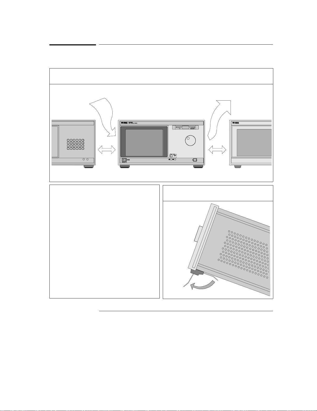
To Set Up the HP 16500B Mainframe
To Set Up the HP 16500B Mainframe
1 Position the instrumen t to allow room for airflow throug h the side and rear pane ls.
CAUTION
Place the mainframe at least 2 inches away
from any wall or away from other
instruments. If there is not adequate space
between the HP 16500B system and other
objects, the system may overheat and may
become damaged.
1–4
2 Set the tilt stands by pulling them forward until
they lock into place. (This step is optional.)
Page 7

Getting Started
To Connect a Mouse
To Connect a Mouse
1 If you have an opition al mou se, proceed to step 2. If you do not have a mouse, go to the nex t pa ge.
2 Plug the end of the m ouse cable mark ed with two dots into the HI L con nect or on t he HP 16500B fr ont
panel.
1–5
Page 8
Getting Started
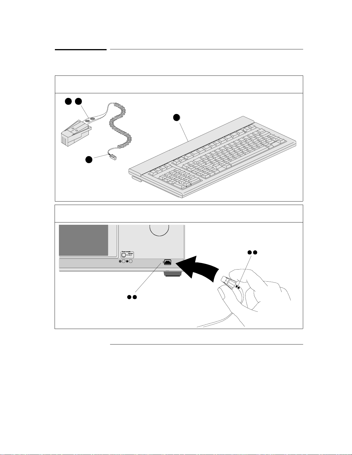
To Connect a Keyboard
To Connect a Keyboard
1 If you have an optional keyboard, plug the end of the cable marked with one dot into the connect or
marked wit h one do t on the back of the keyboard.
2 Plug the end of the keyboard cable marked with two dots into the HIL connecto r on the HP 165 00B
front panel.
1–6
Page 9

Getting Started
To Connect Both a Mouse and Keyboard
To Connect Both a Mouse and Keyboard
1 To use a mouse and keyboar d simulta neou sly, connect the keyboard to the HP 16500B. Plug the
mouse cable into the con nect or marke d w ith two dot s on the back of the key boar d.
1–7
Page 10

Getting Started
To Set Up an HP 16501A Expander Frame
To Set Up an HP 16501A Expander Frame
1 To insert the frame inte rface cable in the connector s, pinch the sides of the cable connect or.
2 Plug one end of the frame inte rface cable firm ly into the co nnec to r on the rear panel of th e HP 16501A
Expander Frame. Plug the other end into the conn ector on the rear panel of the HP 16500B.
1–8
Page 11

To Set Up an HP 16501A Expander Frame
3 Position the expand er frame to allow room for air flow throug h the side and rear pane ls of the
HP 16500B and HP 16501A.
Getting Started
CAUTI O N
Place the mainframe and expander frame
at least 2 inches away from any wall or
away from other instruments. If there is not
adequate space between the HP 16500
system and other objects, the system may
overheat and may become damaged.
1–9
Page 12

Getting Started
To Apply Power to the System
To Apply Power to the System
1 Plug a power cable into the 3-prong socket on
the rear panel. (Repeat for both f rame s if you
have an HP 16501A.)
HP 16500B and
HP 16501A
3 Push the top of the main po wer LINE swit ch on
the rear panel. (Repeat for both f rames if you
have an HP 16501A.)
HP 16500B and
HP 16501A
2 Plug the male end of the power cable into a wall
receptacle.
4 On the front pane l of the HP 1650 0B, set the
power standby sw itch to the ON position.
1–10
HP 16500B
Page 13

To Adjust the Display
Getting Started
To Adjust the Display
1 On power-u p the display may ap pear dim.
3 On power up, the display contras t may be too
low.
2 Turn the small knob on the left to adjust
brightness.
4 Turn the small knob on the right to adjust the
display contrast.
1–11
Page 14

Getting Started
To Disconnect a Mouse, Keyboard, or Trackball
To Disconnect a Mouse, Keyboard, or Trackball
interface cable plug.
2 Pull the plug out of the HIL connector.1 Pinch the spring clips on the sides of the
1–12
Page 15

2
This chapter provides you with the basic information you need to
start operatin g your HP 16500 B Logic An alys is Syste m. It describes
the basic menus and fields and inclu de s informa tion on how to use
each of the user interface devices.
Operating the System
Page 16

Operating the System
The System Configuration Menu
The System Configuration Menu
When you apply power to the HP 16500B, the system takes about 30
seconds to boot up and run through self-tests. After the self-tests are
completed and the operating system is loaded, the System Configuration
menu will appear on screen. It is from this menu that you will start
operating the instrument.
The large blue field on the left side of the display lists the modules that are
installed in the HP 16500B and HP 16501A frames. In the figure below, an
HP 16550A 100 MHz state/500 MHz timing module is installed in slot C of
the HP 16500B mainframe. The Communications field is used to configure
communications between the HP 16500B system and other devices via
HP-IB, RS-232, and the optional Ethernet LAN interface. The Printer Setup
field is used to configure the instrument for working with various printers.
List of
measurement
modules
Communications field
Printer Setup
field
System Configuration Menu
2–2
Page 17

Operating the System
Common Fields
Common Fields
There are four fields on the HP 16500B screen that appear in virtually every
menu. They are the Module selection, Menu selection, Run/Stop and Print
fields. The locations of the fields are shown below, in the Configuration
menu of the HP 16550A 100 MHz state/500 MHz timing module.
The Module field provides access to the various measurement modules that
are installed in the HP 16500B or to the system-level menus, like the
System Configuration menu shown on the previous page. The Menu field
provides access to the control menus within a given module. For example,
when the Module field is set to System, the Menu field provides access to
the disk drives, Utilities menu, and Configuration menu. The Run/Stop field
is used to start and stop data acquisitions. The Print field is used to print
information.
Module selection
field
Menu selection
field
Run/Stop
field
Print field
Common Fields
2–3
Page 18

Operating the System
User Interfaces
User Interfaces
You can use any of four user interface devices to control the HP 16500B
system: the touchscreen and knob on the front panel, the optional mouse,
the optional keyboard and the optional trackball. The fields on the display
- the light and dark blue boxes - can be selected and activated using any of
these interfaces. The following pages show you how to use each of the
interfaces.
The trackball is no longer available for purchase. If you have an HP M1309A
trackball and you would like to use it to control the HP 16500 system, follow the
instructions for using a mouse.
See Also "To Connect a Mouse" on page 1-5.
"To Connect a Keyboard" on page 1-6.
"To Connect Both a Mouse and Keyboard" on page 1-7.
2–4
Page 19

Operating the System
To Use the Touchscreen and Knob
To Use the Touchscreen and Knob
1 To select an item on the display, touch it. Remove your finger fro m the sc ree n to activat e the item.
Dark blue fields can be activated.
2 Use the knob to scroll the display or continuously up date a value in a light blue field.
2–5
Page 20

Operating the System
To Use a Mouse
To Use a Mouse
1 Move the mouse to move the cross-hair cur sor on the HP16500B screen .
2 Press the left mouse butto n to select an item on the display. Dark blue fields can be selected.
2–6
Page 21

Operating the System
To Use a Mouse
3 Press and hold the center mouse button. While holdin g the button down , move the mouse to scrol l the
display or to continuously update the value of a light blue field.
2–7
Page 22

Operating the System
To Use a Keyboard
To Use a Keyboard
1 Use the arrow ke ys to mo ve the whit e, invers e-v ideo cur sor on the display .
2 Press Return key to select an it em on the display. Dark blu e fields can be se lect ed.
2–8
Page 23

Operating the System
To Use a Keyboard
3 Press and hold the Shif t key. Then, use the arrow keys to scroll th e display or to continuou sly upda te
the value of a light blue field.
2–9
Page 24

Operating the System
What’s Next?
What’s Next?
Now that you have unpacked, inspected, and begun operating the
instrument, your next step depends on your own needs. To begin exploring
your measurement modules, activate the Module field, in the top left corner
of the display. From the pop-up menu, select a module that you want to
start using.
If you are a first-time user and would like more information about your logic
analysis system, read the two books,
and
Analyzers
If you want to learn more about the system interface and get hands-on
training using the HP 16500B system to make real measurements, try some
of the exercises in the
training kit show you how to set up basic measurements through
step-by-step procedures.
If you are familiar with logic analyzers and digitizing oscilloscopes, you may
want to go directly to the
measurement module references. The references explain the functions and
features of the HP 16500B System in a detailed, encyclopedia format.
Feeling Comfortable with Digitizing Oscillosco pe
Logic Analyzer Training Kit
HP 16500B System User’s Reference
Feeling Comfortable with Logic
s.
. The exercises in the
and similar
2–10
Page 25

3
If You Have a Problem
Page 26

If You Have a Problem
If you press the power standby switch and nothing happens
If you press the power standby switch and nothing
happens
Set the power standby switch back to the standby postition.
Make sure that the power cable is firmly plugged into the rear of the
instrument and a power supply outlet.
Make sure that the main power switch on the rearpanel is on, by
pressing the top of the switch.
Check the LINE SELECT switch, on the rear panel, to ensure that it is
set to the proper input voltage level for your power supply.
Check to see whether the fuse is intact.
See Also "To Select the Proper Line Voltage" on page 3-4.
"To Check the Fuse" on page 3-4.
If the instrument is on, but the display is dark
Adjust the brightness and contrast controls on the front panel.
See Also "Adjusting the Display" on page 1-11.
3–2
Page 27

If You Have a Problem
If an "Unrecognized Card" message appears in the System Configuration menu
If an "Unrecognized Card" message appears in the
System Configuration menu
Turn off the power.
Securely seat the module that is not being recognized by pressing on
the center of the module backing plate and by turning the thumb screws.
Turn on the power.
If this problem persists, verify that the hard disk contains the operating
system software file for the card that is not being recognized. To check
for the correct operating system:
1 Select the System, Hard Disk menu.
2 Select the Load field, then select Change Directory.
3 Use the knob to highlight the SYSTEM subdirectory, then select
Execute.
4 Verify that a file called sys_xxx is present on the hard disk. There
should be a file whose File Description matches the description of
the card that is not being recognized.
5 If there is not a sys_xxx file with a description that matches the card
that is not being recognized, you can copy the file that you need from
the flexible disks labeled "Operating System for the HP 16500
System. Copy the appropriate system file from these disks to the
\system subdirectory on the hard disk.
6 Turn the power off and then back on to reboot the system.
3–3
Page 28

CAUTION
If You Have a Problem
To Select the Proper Line Voltage
To Select the Proper Line Voltage
Use the LINE SELECT switch on the rear panel of the instrument to select
the appropriate voltage level for your power system. The selections are
110 Volts or 220 Volts. To change the setting:
Using a small screwdriver, push the switch to the left or right until
1
the desired line voltag e is displa ye d.
Make sure that the LINE SELCT switch is set to the proper voltage for your
power supply. The HP 16500B and HP 16501A can be damaged if the
LINE VOLTAGE switch is no set to match the input voltage.
To Check the Fuse
1 Push in the fuse holder gently and turn the top of the fuse holder
counter-clockwise about one quarter of a turn until the top pops out.
2 Remove the fuse and check that it is intact.
3 Check the value that is marked on the fuse.
The correct value for each line voltage selection is printed on the top of the
power supply (under the top cover) and in the HP 16500B/16501A Service
Guide.
WARNING
WARNING
To Install the Fuse
1 Put the top of the fuse holder onto the fuse and gently push the fuse
into the holder on the rear panel.
2 Turn it clockwise un til it seats itse lf. Then, push in gently and turn it
about one quarter of a turn .
Make sure the instrument is turned off and unplugged before checking the
fuse. Failure to do so could result in electric shock.
Replace fuses with the same type and rating specified in the HP
16500B/16501A Service Guide, for continued protect ion against fire hazard.
3–4
 Loading...