


Errata
16500B Users Reference
16500-97010
April 1994
Title & Document Type:
Manual Part Number:
Revision Date:
HP References in this Manual
This manual may contain references to HP or Hewlett-Packard. Please note that HewlettPackard's former test and measurement, semiconductor products and chemical analysis
businesses are now part of Agilent Technologies. We have made no changes to this
manual copy. The HP XXXX referred to in this document is now the Agilent XXXX.
For example, model number HP8648A is now model number Agilent 8648A.
About this Manual
We’ve added this manual to the Agilent website in an effort to help you support your
product. This manual provides the best information we could find. It may be incomplete
or contain dated information, and the scan quality may not be idea l. If we find a better
copy in the future, we will add it to the Agilent website.
Support for Your Product
Agilent no longer sells or supports this product. You will find any other available
product information on the Agilent Test & Measurement website:
www.tm.agilent.com
Search for the model number of this product, and the resulting product page will guide
you to any available information. Our service centers may be able to perform calibration
if no repair parts are needed, but no other support from Agilent is available.

User’s Refer ence
Publicat ion num ber 16500-97010
First edition, April 1994
For Safet y inform ation, W arran ties , and Regulat or y
infor m at ion, see the pages behind the index
Copyright Hewlet t-Packard C om pany 1987, 1990, 1993 , 1994
All Right s Reserved
HP 16500B/16501A
Logic Analysis Sy stem


In This Book
Welcom e to th e Hewlet t-Packar d Logic
Analys i s System ! The HP 16500B Logic
Analys i s System is de signed to be the
eas iest system to us e, ever. Its m odular
design allows you to conf igur e it with jus t
th e m eas ur em ent m odules you need now ,
yet add ot her m odules lat er .
This refer ence explains the oper a tion of
th e system mainfram e and Interm o dule
m enus. Also include d is infor m ation on
th e most com m on system opt ions.
Organizat i on
When you or der the HP 16500B, you get
tw o binders (one is ext ra for later use ).
The mainfram e refer ence inform ation is
found be hind the first tab "HP 16500B
Mainfram e."
Infor m ation on th e optional keyboar d,
mouse, and th e HP 1650 1A Expansion
Fram e is found behind the sec o nd tab,
"System Options." As you accum ul at e
other system opt ions , place th e se
refer ences behind th is tab.
Behind th e th ird tab "Common M odule
Operations " is infor m ation common to
most m odules , like installing m odules,
using sym bol s, a nd as signing label s.
As you pur chase additional m easur em ent
m odules , place th e ir refer ences at the
back of this binder or in the second
binder.
1
2
3
4
5
6
7
8
9
10
What is the HP 16500B
Logic Analysis System
System Configuration Menu
The HP-IB and RS-232C Interfaces
Connecting a Printer
Disk Drive Menus
System Utilities Menu
Intermodule Measurements
General Characteristics
Maintaining the HP 16500B
Error Messages
Index

What is in th e HP 16 500B User’s Reference?
Chapter 1 intr o duces th e HP 16500B by summarizi ng its features.
•
Chapter 2 discri bes th e mainfram e’s System Configur at i on m e nu.
•
Chapter 3 discri bes th e HP-IB and RS-232C inter faces. They ar e used for
•
printing s cr eens a nd com put er cont rolled m easur em ent s .
Chapter 4 explai ns how to print s cr eens to various graphics pr inte rs .
•
Chapter 5 discri bes th e flexible disk and ha rd disk operat ions.
•
Chapter 6 des cribes th e Sys tem Utilities m enu. Adju stm en ts to the
•
real-time cloc k, touch calibration, and s cr een color s ar e made he re.
Chapter 7 explai ns how to make interm odule m easur em ent s .
•
Chapter 8 lists the ins trum ent speci ficat ions and char acter isti cs .
•
Chapter 9 explai ns th e gener al instru m ent maint enance and repacki ng
•
infor m ation. Also inc lude d is a description of the sel f-test tha t is
perfor m ed when the instrum ent is turned on.
Chapter 10 describes all system a nd disk error m es sa ges.
•
What is in th e System Options?
Chapter 1 explai ns th e keyboa rd and mouse options.
•
Chapter 2 des cribes th e HP 1650 1A Expansion Fram e opt ion. Even
•
though you may no t have pur chased these opt ions yet, keep this
infor m ation for possi ble future us e .
What is in th e C om m on Module Operations?
Chapter 1 des cribes assi gning label s.
•
Chapter 2 des cribes us ing sym b ol s.
•
Chapter 3 explai ns th e gener al instal lat ion for individua l m odules.
•
W her e to go next
If you haven’t al ready read
System
MS-DOS
, please read it befor e cont inuing.
is a US r egistered t radem ark of Micr osof t Corporation.
Settin g Up The HP 16500 Logic Analys is

HP 16500B
Mainfram e
Content s
1What Is th e HP 16500B Logic Analysis System?
Key Features 1–3
Optional Features 1–3
User Inter faces 1–4
Default Configur at ions 1–4
A ccessories Supplied 1–5
A ccessories A vailable 1–5
2The System Configuration Menu
Getting into the Sy stem Configur at i on M enus 2–4
Layout of the Sy ste m Configura t ion M enus 2–5
Slot Design ators 2–6
3Configuring th e HP-IB and RS-232C
Configur ing th e HP-IB Interface 3–4
Configur ing th e RS-232C Interface 3–5
Configur ing th e Interface for a Contro ller or Printer 3–8
4 Connecting a Printer
C on necting HP-IB Printers 4–3
C o nn ecting RS-23 2C Printers 4–6
C o nn ecting to Other Hewlett-P ackard Printers 4–9
Printing the Displ ay 4–11
Contents– 1

Contents
5The Disk Drive M enus
A ccessing th e Disk M enus 5–5
Ins tal ling a Flexible Disk 5–6
Selecting a Disk Operation 5–7
Loading a File 5–8
Form atting a Disk 5–10
Storing Files on a Disk 5–12
Renam ing a File 5–15
Autoloading a File 5–17
Purging a File 5–19
Copying a File 5–20
Packing a Disk 5–22
Duplicat ing a Disk 5–23
Making a Directory 5–24
Changing th e Dire c tory 5–25
Creating a Sys tem Flexi ble Disk 5–26
6The System Utilities Menu
The Touch and Sound Fields 6–4
Touch Calibr ation 6–4
Setting th e Real-time Clock 6–6
Turning the Sound On/Off 6–7
Disp lay Color Selection 6–8
Selecting th e Color, Hue, Sa tur ation, a nd Lum inosity Fiel ds 6–10
Selecting Colors 6–12
Returning to th e Defaul t Colors 6–14
Conten ts–2

7 Interm odule M eas urem ents
A ccessing th e Interm odule M enu 7–5
Configur ing a Group Run 7–6
Configur ing Port In/O ut 7–8
The G roup Run/Stop Field 7–10
The M odules List 7–11
Status Indicat or s a nd Time C orrelat ion B ars 7–12
Adjusting Skew 7–13
What Are Som e Typical Interm o dule M easurem ents? 7–14
Disp laying Multiple M odule Data on One Screen 7–18
Helpful Hints 7–21
8 G eneral Characteristi cs
Char act eristics 8–2
Contents
9Maintaining th e HP 16500B
Cleaning Requirem en ts 9–2
D egaussing 9–3
Service and Calibr ation 9–3
The System Test M enu 9–4
R e packag ing for Stor age or Shipm ent 9–5
1 0 E rror M essages
Disk E rror M essages 10–3
Disk Warning M essages 10–5
Pow erup Self-Test Docum entat ion 10–6
Fail Codes 10–7
Critical E rro rs 1 0 –8
Non-Critical E rro rs 1 0– 8
Contents–3

System Options
Contents
1Using the Optional K eyboard and Mouse
Moving the Cursor 1- 3
Enter ing Data into a M enu 1-5
Using the K eyboar d Overlays 1- 7
Defining Time Units 1-9
Defining Voltage Units 1-9
Assigning Edge Triggers 1- 10
Closing a M enu 1- 10
Connecting th e K ey board a nd Mouse 1-11
2The Option HP 16501A Expansion Fram e
Component Details 2-3
System Configur at i on 2- 4
System Arming a nd Trigger ing 2-4
Connecting th e HP 16 501A Expansion Fram e 2-7
Com m on Module
O per ations
1 Labels A ssi gnm ent
Label A ssi gnm ent Fields 1- 3
Rolling Labels and Pods 1-5
2 Sy m bols A ssi gnm ent
Sym bols Field 2- 3
3Installing and Rem oving Cards
General Ins ta llation Proc e dure 3-3
HP 1653 2A Ins tallat ion Considerations 3-7
HP 1651 7A/18A Installation Considera tions 3-11
Content s–4

1
What Is the HP 16500B Lo gic Analysis Sys tem ?

The HP 16500B
The HP 16500 B is the mainfram e of the Hewlet t-Packard Logic
Analysis System . It of fers a modular structure for plug-in car ds with a
wide ran ge of stat e, timing, oscillos c ope, a nd patter n gener at or
capabilities. This allow s you to conf igur e the HP 16500B using only
the m odules you nee d in or der to perform a desired m eas ur em ent or
set of m easur em ent s, while gi ving you the flexibility to change or
update the m lat er .
The Lo gic Analys is System prov ides both exper ienced and first-time
us e rs with powe rful m easur em ent capabilities . The po p-up m enus
and color g raphics lead you thr o ugh setups and m easur em ent s quickl y
and easily, without the need to memorize a lot of st eps. By touching
the a ppropriat e fields or using the cur sor of eithe r the opt ional mouse
or keyboard, you can perfor m func tions, conf igur e menus, and move
from one menu to anot her.
With the interm odule capabilities of the Logic Analysis System , you
can make inter act ive m easur em ent s betw een m odules . This allow s
you to conf igure modules to inter act with each other, us ing the
trigger ing capabilities of one module and the acquisi tion capabi lities of
anot her.
System Options
The HP 16501 A is the add- on mainfram e for e xpa nding the m odule
capacity of the HP 16500B. When the HP 16501A is connect ed to the
HP 16500B, they function as a si ngle ten-card system which is turned
on and cont rolled by the HP 16500B. The HP 16501A form s a tight ly
c oupled system with the HP 16500B, pe rm itting each of the two
mainfram es to ar m or trigger any module from any other m odule.
An opt ional LAN inter f ace is availabl e for direct connect ion to
com put er s locat ed on an Ethernet local ar ea network (LA N ). The
LAN inter face enables you to upload m eas urem ent data for the most
c om prehe nsive pos t-pr ocess ing ne e ds a nd eas y access to da ta files.
1–2

What is the HP 16500B Logic Analysis System
Key Feat ures
The key feat ures of th e HP 16500B ar e:
M odular mainfram e with five car d sl ots.
•
9-inc h color monitor.
•
Touc hscree n with on/off cont rol.
•
Batter y backed R eal-time clock.
•
Program m able PORT IN vol tag e level a nd edge sel ect ion.
•
3.5-inc h flexible disk dr ive with DOS and LIF for m at s uppo rt.
•
170 Mbyte hard disk drive with DOS for m at support.
•
Interm odule trigge r ing a nd 2 ns time correlat ion of ac quired data.
•
HP-IB and RS-232C inter faces for :
•
— Hardcopy output to a printer
— Controller interface.
Key Features
Optiona l Features
The opt ional feat ures of th e HP 16500B:
HP 1650 1A Expa nsion Fra me. Increase avai lable car d slots to ten when
•
you connect th e expa nsion fram e to an HP 16500B.
Mouse.
•
Keyboa rd.
•
Ethe rnet LAN interface.
•
Expandable system memory up to 64 Mbytes.
•
See Also "System Options" for more infor m ation on availabl e system softw a re and
hard w are opt ions .
1–3

What is the HP 16500B Logic Analysis System
User Interfaces
User Inter faces
The HP 16500B has four user interface de vices: th e knob on th e fro n t pa ne l,
th e touc hscree n, the opt ional mouse, and the opt ional key board.
The knob on th e fron t pane l is us e d to m ove th e cur sor on cer t ai n m enus,
inc rem ent or decr em ent num e ric fiel ds, a nd to roll the displ ay.
The touchs creen fiel ds can be sel ect e d by touch or with the opt ional mouse
or keyboa rd. To act ivate a fiel d by touch, press th e dark blue field on th e
displ ay with your fing e r until the field changes col or . Then m ove your finge r
aw ay from the s cr een to act ivat e your select ion. Yo u have th e option of
disabl ing the touchs c ree n with the fron t-pa ne l Touch On/Off but ton.
See Also The "System Options " part for more infor m ation on us ing the optional
key board and mouse.
Screen Contrast and Bright ness
Scr een cont rast and bright ness ar e adj usted by turn ing the two sm al l knobs
locat ed be neath th e Touc h Sc ree n button. The lef t knob is for br ight ness and
th e right knob is for cont rast.
Default Configur at ions
When the instrum ent is po wered up, predeter m ined val ues ar e au tom atically
assi gned to th e different fields of the m enus to conf igur e th e instru m en t for
basic m eas urem ent s . This al low s you to make a bas ic m easur em ent by
tu rn ing on the ins tru m ent, connect ing the pr obes, a nd touc hing the Run
field. Often, only minor changes ar e needed for more com plex m easurem ent s.
Storing Default Configurat ions
The default conf igur ations m ay be stored on a disk for lat er us e or reset by
cycling the power. Storing defaul t conf igurat ions on a disk is a conveni ent
way to return to th e defaul t value s without cycling the po wer. Defaul t values
for each m odule can be st or ed separately or toget her in one file.
See Also The "Using th e Disk Drive M enus" chapt er for more infor m ation on the Store
operat ion.
1–4

What is the HP 16500B Logic Analysis System
Accessories Supplied
Access or ies Supplied
The following list of access ories is supplied with th e HP 16500B Logic
Analys i s System . If any access ory is missi ng, cont act your local sal es office.
Accessories Supplied Qty
Training Kit 1
User’s Reference Guide 1
Programming Reference Guide 1
Service Guide 1
Setting Up the System Guide 1
RS-232C Loopback Connector 1
Power Cord 1
Disk pouch containing composite software 1
Feeling Comfortable With Logic Analyzers guide 1
Feeling Comfortable with Digitizing Oscilloscopes guide 1
Filler Panels
*
Quantity depends on how many m odules ar e order ed with th e HP 16500B/16501A
*
Access or ies Available
Other access ories avai lable for th e HP 16500B /16501A Logic Analysis System
ar e listed in the
A ccessories for HP Logic Analyze rs
br ochur e.
1–5

1–6

2
The System Configur ation Menu

The Sy stem Configur ation Menu
The Sy stem Configura t ion m enu is the first m enu you see af ter the
initial power-up of the instrum ent. This m enu lists the m odules and
sof tware options that your system is conf igur ed with and show s
whether there ar e five car d sl ots (the HP 1 6500B alone) or ten car d
sl ots (t he HP 1650 0B with the optional HP 16501A at tached)
available. It also sh ow s if either the optional mouse or keyboar d is
connect ed. If a mouse is connect ed, the system conf igur at ion menu
indicat es whether the mouse is connect ed directly to the HP 1650 0B
or to a keyboar d connect ed to the mainfram e. Fina lly, the system
conf igur ation menu gives you access to the conf igur ation of the HP-IB,
RS-232C, and opt ional LAN inter f aces.
2–2

The System Configuration Menu
Menu Map
The follow ing menu map illus trates all fields a nd availabl e options in
the System Configur at ion m enu. The menu map will help you get an
ove rview as well as prov ide you with a quick reference of what the
System Configur at ion menu cont ains .
System Configuration Menu Map
2–3

The System Configuration Menu
Getting into the System Configuration Menus
Getting into the Sy stem Configur ation M e nus
In the uppe r-left cor ner of th e m enu ar e tw o fields tha t indicat e the cu rrent
m enu a nd m odule. The field to the ext rem e left (System ) show s you which
m odule you’re in and the one to the right of the m odule field (C onf igur ation)
show s you what m enu within the m odule you’ve acces sed.
To access the Sy stem Configur ation m enu, follow these st eps:
If the m odule field in the upper-left cor ner of the scr een does not
1
displ ay "Sys tem ," sel ect this field and when the pop-up appear s , sel ect
System. This will get you into one of the System m enus.
2 If the m odule field in the uppe r-left cor ner of the scr een displ ays
"Sy stem ," but the m enu field to the ri ght of Sys tem doesn’t displ ay
"Configur ation ," sel ect this field. When the pop-up appears , sel ect
Configuration to displ ay the Sy stem Configur ation menu.
Module field Menu field
Module and Menu Fields
2–4

The System Configuration Menu
Layout of the System Configuration Menus
Layout of the Sy stem Configur ation M e nus
The figure below sh ow s the layout of the Sy stem Configur at i on m e nu for the
HP 1650 0B. The figur e is labelled with the major feat ures and func tions of
th e m enu.
Module list
Slot designators
Module
Module
Module
Module
Module
System Configuration Menu
Keyboard
Mouse
Select HP-IB
or RS-232C
Printer setup
2–5

The System Configuration Menu
Slot Designators
Slot Designat ors
The sl ot de signat or s are listed as A throug h E for the HP 16500B alone, or A
throug h J for the HP 16 500B with the HP 16501A at t ached. The slot
designat or s are displ ayed to th e lef t of th e list of car ds for the system and
indicat e the locat ions or sl ot s for each car d. When you sel ect th e Module
field, a po p-up appears . The let ters after the nam e of each m odule indicat e
th e location of each “m aster” card for th a t m odule.
System System
Intermodule
A
B
C
D
E
Slot Designators in Master Frame
Module in first slot
Module in second slot
Module in third slot
Module in fourth slot
Module in fifth slot
2–6

3
Configur ing the HP-IB and RS-232C

The HP-IB and RS-232C Interfaces
This chapt er de scribes the cont roller and printer inter f aces and their
conf igur ations. It defines the HP-IB inter face and des cribes how to
sel ect any one of the 31 differ e nt HP-IB addr esses available. It also
defines the RS-232C inter f ace a nd tells you ho w to sel ect a baud rate,
how to change the stop bits, how to set the parity a nd da ta bits, and
how to change the protocol.
Select HP-IB
or RS-232C
Controller and Printer Configuration
3–2
Printer setup

Configuring the HP-IB and RS-232C
The Controller Interface
The HP 16500 B is equippe d with a standar d RS-232C inter face and an
HP-IB interface that al low you to connect to a cont roller. This gives
you rem o te access for running m easur em ent s, for uploading and
downloading conf igur at ions and da ta, for printing , and more. The
cont roller inter face is e xplained in more detail in the
HP 16500B/16501A Pr ogram m er ’s Guide
.
The Printer Interface
The HP 16500 B can out put its s cr een displ ay to various HP-IB and
RS-232C graphics printers . Configur ed m enus , w avef orm s , and other
da ta can be pr inted for com plet e m eas ur em ent docum entat ion. The
printer inter face is e xplained in more detail in chapt er "Connec ting a
Printer ."
3–3

Configuring the HP-IB and RS-232C
Configuring the HP-IB Interface
Configur ing the HP-IB Inter face
The Hewlet t -Packar d Inter f ace Bus (H P-IB) is Hewlet t-Packard’s
implem ent at ion of IEEE Standa rd 488-1978, “Sta ndard Digital Inter face for
Program m able Instrum enta tion.” The HP-IB is a car ef ully defined interface
th at si mplifies the integ ra tion of var ious instrum ents and c o m puters into
system s. It us e s an address ing tec hnique to ensur e th at each device on the
bus (i nter connect ed by HP-IB cables) receives only the data intended for it.
To accom pl ish this, each dev ice is set to a differ ent address a nd this address
is used to co m m unicat e with other devi ces on the bus.
Selecting an HP-IB Address
The HP-IB address can be set to 31 differ ent HP-IB a ddress e s, from 0 to 30.
Simply choose an a ddress that is com pat ible with your dev ice or softw a re .
The default is 7.
Select the Communications fiel d.
1
2 Using the knob or keypad, ent er an HP-IB addr ess in the field dir ectly
under "HP-IB Address."
To use the keypad, sel ect the HP-IB Address field a nd a pop-up keypad will
a ppe a r. Then, ent er th e a ddress and sel ect Done.
When you ar e finished conf iguring the HP-IB Address, sel ect Done.
3
HP-IB address field
Communications field
Communications Configuration pop-up Menu
3–4

Configuring the HP-IB and RS-232C
Configuring the RS-232C Interface
Configur ing the RS-232C Inter face
The RS-232C inter face on this instru m ent is Hewlett-Packar d’s
implem ent at ion of EIA Rec o m m ende d Standard RS-232C, “Interface Betw een
Data Termina l Equipm e nt a nd Data Com m unicat ions Equipm ent Em ploy ing
Serial Binary Data Inter change.” This interface s e nds data one bit at a time,
a nd char act er s ar e no t sync hronized with preceding or subseq uent data
char act ers . E ach char act er is sent as a com plet e ent ity without relat ionship
to ot her event s.
Baud Rate
The ba ud rate is th e rate at which bits are tran sferred betw een the interface
a nd the peripheral. The ba ud rate must be set to transm it a nd r ecei ve at the
sam e rate as the pe ripheral, or da ta cannot be success f ully tran sferred .
Select the Communications fiel d.
1
2 Select the RS-232C field loc a ted dir ectly under the HP-IB A ddr e ss field.
3 When the pop-up menu appear s, sel ect the field dir ectly to the right of
“B aud Rate.”
Baud rate
RS-232C Configuration
3–5

Configuring the HP-IB and RS-232C
Configuring the RS-232C Interface
4 When the s econd pop-up appear s, select the ba ud rate you want from th e list
displ ayed in the pop-up (110 to 19.2k) and the po p-up will disappe ar.
Stop Bits
Stop bits ar e use d to identify the e nd of a char act er. The num be r of stop bits
must be the sam e for the cont r ol ler as for th e Logic Analys is System .
Select the Communications fiel d.
1
2 Select the RS-232C field loc a ted dir ectly under the HP-IB A ddr e ss field.
3 Select the field dir ectly to the right of “S top Bits” in the RS-232C
Configur ation pop-up m enu.
4 When the new pop-up appear s , sel ect 1, 1.5, or 2 st op bits to ide ntify
the end of the char acter. The pop-up disappears, placing your
sel ect ion in the a ppropriat e field.
Parity
The pa rity bit de tect s errors as inc o m ing charact er s ar e r eceived. If the
pa rity bit does not match the expected value, th e charact er is as sum ed to be
incorrectly r ecei ved. The action t aken when an erro r is det ect ed de pe nds on
how th e interface a nd the devi ce pr ogr am ar e conf igur ed.
Parity is dete rm ined by th e req u irem en ts of the system . The parity bit may
be inc lude d or om itted fro m each char act er by enabling or disabl ing the
pa rity function.
Select the Communications fiel d.
1
2 Select the RS-232C field loc a ted dir ectly under the HP-IB A ddr e ss field.
3 Select the field dir ectly to the right of “P arity” in the RS-232C
Configur ation m enu.
4 When the pop-up appears , sel ect None, Odd, or Even to match the
parity of the exter nal device. After you make your sel ection, the
pop-up disappears.
3–6

Configuring the HP-IB and RS-232C
Configuring the RS-232C Interface
Prot ocol
Protoco l gover ns th e flow of data betw een the instrum ent a nd th e ext ernal
device.
Select the Communications field.
1
2 Select the RS-232C field loc a ted dir ectly under the HP-IB A ddr e ss field.
3 Select the field dir ectly to the right of “P rotocol” in the RS-232C
Configur ation pop-up m enu.
4 When the pop-up appears , sel ect None or Xon/Xoff.
None
With les s th an a 5-wire interface, sel ect ing None does not al low th e
•
sending or r ecei ving device to cont rol how fast th e data is being sen t. No
cont r ol over the data flow inc rea ses the possi bility of missi ng data or
tran sferring inc o m plet e data.
With a full 5-wire inter face, sel ect ing None al low s a h ard w are hands hake
•
to occur . With a h ardw are handshak e , h ardw are si gnals cont rol data flow .
The HP 13242G cable al low s the HP 16500B to suppo rt h ardw are
ha ndshak e .
Xon/Xoff
Xon/Xoff st ands for Transm it On/Transm it Off. With this mode, th e
•
r ecei ver cont rols the data flow and can request tha t the printer stop data
flow at any time.
Select Done.
5
Data Bits
Data bits ar e the num ber of bits sent a nd received pe r char act er that
r epr es ent the binary code of that charact er. The HP 1650 0B supports the
8-bit binary code.
3–7

Configuring the HP-IB and RS-232C
Configuring the Interface for a Controller or Printer
Configur ing the Inter face for a Contro ller or Printer
Both the HP-IB and RS-232C interfaces can be conf igured for either a
cont roller or a printer. You can sel ect th e inter face and what it cont r ols
(printer or cont r oller ) in either of two places. When one inter face is
conf igur ed to either the printer or cont r ol ler, the othe r interface is
aut om at ically sw i tched to th e ot he r. One interface is never conf igur ed to
cont rol both.
• In the Printer Setup m enu, toggle the Printer Connected to: field.
• In the Communications menu, set the Controller Selection field.
For exam ple, one way to conf igur e th e RS-232C inter face for a printer:
Select the Printer Setup field, the n toggle the Printer Connected to: field to
1
RS-232C.
Printer interface
toggle field
RS-232C Printer Configuration
Any HP-IB typ e printer must be set to Listen Always for the HP-IB inter face.
Also, in this mode no HP-IB address ing is necess ar y.
See Also The "Connec ting a Printer" chapt er for more infor m at ion on us ing a printer.
3–8

4
Conne c ting a Printer

Connecting a Printer
The HP 16500 B can out put its s cr een displ ay to various HP-IB and
RS-232C graphics printers . Configur ed m enus , w avef orm s , and other
da ta can be pr inted for com plet e m eas ur em ent docum entat ion.
4–2

Connecting a Printer
Connecting HP-IB Printers
Connec ting HP-IB Printer s
The HP 16500B interfaces directl y with HP PCL printer s s upporting th e
printer command language or with Epson printe rs supporting the Epson
standa rd com m and set. These printers must also s upport HP-IB and Listen
Alw ays. Printers curren tly available from Hewlet t-Packar d with th e se
featur e s include:
HP ThinkJ e t.
•
HP Quiet J et.
•
HP LaserJet.
•
HP PaintJ e t.
•
HP D eskJet.
•
HP D eskJetC
•
The printer must be in Listen Always when HP-IB is th e printer inter face. In
a ddition, the HP 16500B HP-IB po rt does not respond to servi ce requests
(SR Q ) when cont rolling a printer. The SRQ enabl e setting for the HP-IB
printer has no ef fect on HP 16500B printer oper ation.
HP-IB Printer Setup
Turn off the HP 16500B and connect an HP-IB cable fro m the pr inter
1
to the HP-IB connect or on the r ear panel as show n below .
HP-IB Connector on Rear Panel
4–3

Connecting a Printer
Connecting HP-IB Printers
2 Make sure the printer is in the Listen Always (or Listen Only) mode.
For exam pl e, the figur e below show s th e conf igur at ion sw itch e s for an HP-IB
Think Jet printer . For the Listen Always mode, move th e s e c o nd sw i tch from
th e lef t to the “1" po sition. Sinc e the HP 16500B doe sn’t respond to SRQ EN
(Service Reque st Enable) , the po sition of the first sw i tch doe sn’t matter.
Configuration Switches for the HP ThinkJet Printer
HP-IB In stru m ent Setup
1 Turn on the HP 16500B. From the Sy stem C onfigur at ion m enu, sel ect
Printer Setup field.
the
2 When the Printer Configur at ion m enu appear s , toggle the Printer
Connected to:
3 Select the field to the ri ght of “P rinter .” When the printer select ion
field to HP-IB.
pop-up appear s, sel ect the printer that y ou’re using (s uc h as ThinkJ e t,
QuietJet). If you’re using an Eps on g raphics pr inter or an
Epson-com patible printer , sel ect
4–4
Alternate.

Interface type
Printer selection
Print width
Page length
Connecting a Printer
Connecting HP-IB Printers
4 Select the field to the ri ght of "Print Width" and depe nd ing on your
applicat ion, toggle the width to either
Print width te lls the printer th at you are s e nding up to 80 or 132 char act ers
per line (w hen you Print All) a nd is totally independent of the printer itself.
80 or 132.
HP-IB Printer Configuration
If you sel ect 132 char act er s per line when us ing other tha n the Quiet Jet
•
sel ect ion, th e listi ngs are pr inte d in a com pressed mode. Com pressed
mode us e s sm aller char acter s to allow th e printe r to print more char act er s
within a given ar ea.
If you sel ect 132 char act er s per line for the Quiet Jet sel ect ion it can print
•
a full 132 charact er s per line with ou t going to com pr essed mode, but the
printer must have wide r pape r.
If you sel ect 80 character s per line for any printer , a maximum of 80
•
char act er s ar e printed pe r line.
Select the field to the ri ght of Page Length. Depe nding on y our
5
applicat ion, toggle it to eithe r
Page lengt h tells the printer th e page lengt h for th e ty p e of pa pe r you ar e
using.
Select Done when you finished.
6
11 or 12.
4–5

Connecting a Printer
Connecting RS-232C Printers
Connec ting RS-232C Printer s
The HP 16500B interfaces directl y with RS-232C pr inter s , inc luding the HP
Think Jet, HP Quiet Jet, HP Lase rJe t, HP PaintJet, HP DeskJet and
HP D eskJetC printers .
RS-232C Printer Setup
Turn off the HP 16500B and connect an RS-232C cable (H P 13242G )
1
from the printer to the RS-232C connector on the rear pa nel.
RS-232C Connector on Rear Panel
4–6

Connecting a Printer
Connecting RS-232C Printers
2 Before turning on the pr inter , set the mode sw i tches as follow s:
The HP Quiet Jet seri es printe rs have tw o banks of mode function sw i tch es
•
inside the fron t cover. Push all the sw i tch es do wn to the “0" position as
show n in th e figur e below .
Switch Configuration for HP QuietJet Printers
For the HP 2225D (R S-232 HP ThinkJ et) printer , the mode sw i tches are
•
on th e rear pane l of th e printer . Push all th e sw i tches down to the “0"
position as in the figur e below.
Switch Configuration for HP ThinkJet Printers
For the HP LaserJe t printer, th e sw i tch settings can rem ain in the fact ory
•
default settings.
4–7

Interface type
Printer selection
Print width
Page length
Connecting a Printer
Connecting RS-232C Printers
RS-232C Instru m en t Setup
Turn on the HP 165 00B and from the Sy s tem Configur ation menu,
1
sel ect the
2 When the Printer Configur at ion m enu appear s , toggle the Printer
Connected to:
Printer Setup field.
field to RS-232C.
RS-232C Printer Configuration
3 Select the field to the ri ght of “P rinter .” When the printer select ion
pop-up appear s, sel ect the printer that y ou’re using (s uc h as ThinkJ e t,
QuietJet). If you’re using an Eps on g raphics pr inter or an
Epson-com patible printer , sel ect
Select the field to the ri ght of "Print Width." Depe nding on y our
4
applicat ion, toggle the width to either
Print width te lls the printer th at you are s e nding up to 80 or 132 char act ers
per line (w hen you Print All) a nd is totally independent of the printer itself.
Select the field to the ri ght of "Page Leng th." Depending on your
5
applicat ion, toggle it to eithe r
Page lengt h tells the printer th e page lengt h for th e ty p e of pa pe r you ar e
using.
Select Done when you finished.
6
4–8
Alternate.
80 or 132.
11 or 12.

Connecting a Printer
Connecting to Other Hewlett-Packard Printers
RS-232C I nter face Setup
From the Sys tem Configur ation m enu, sel ect the Communications field.
1
2 From the Com m unicat ions Configur at ion menu that appear s, sel ect
the RS-232C field just to the right of the HP-IB Addr e ss field.
3 From the RS-232C Configur at ion m enu that appear s , set the baud
rate, stop bits, pa rity, a nd protocol depe nding on your a pplicat ion.
For com plete inform ation on thes e RS-232C interface para m eter s go
to "What is the RS-232C Inter f ace" section in the HP-IB and RS-232C
chapt er found earlier in this m anual.
Connec ting to Othe r Hew let t-Packar d Printer s
The HP 16500B can also be used with ot her Hewlet t-Packar d graphics
printer s . Simply connect th e printer to the HP 16500B using th e appropriat e
cabl e (H P - IB or RS-232C) and conf igur e th e HP 16500B as show n in the
follow ing table.
HP Printer Selection
For this HP Printer Select this Printer from the pop-up
HP 2631G QuietJet
HP 2671G ThinkJet
HP 2673A ThinkJet
HP 9876A ThinkJet
HP 2932/34 (option 046) QuietJet
4–9

Connecting a Printer
Connecting to Other Hewlett-Packard Printers
HP-IB printer s must support Listen Alw ays to work with th e HP 16500B. The
HP 8290 6A graphics printer is not s uppo rted because it does not s uppo rt
Listen Always on HP-IB.
The HP 2932A or HP 2934A opt ion 046 printer is conf igur ed fro m th e fron t
pa ne l of the printer, instead of with sw i tch es on th e re ar pa nel. The cor rect
conf igur ation for the HP 16500A is show n in the figur e below .
See Also Refer to th e
up an ext er nal cont roller to act ivat e the printer.
Configuration for the HP 2932/34 Option 046
HP 16500B Program m ing M anual
for infor m ation on setting
4–10

Connecting a Printer
Printing the Display
Printing the Displ ay
E ach m enu has a Print field in the upper-right cor ner . Select the Print field
a nd a pop-up appears , displ aying your choi ces . Depending on th e
m eas ur em ent m odule and m enu you ar e printing, only som e of the follow ing
choices will appear .
Cancel stop s the print.
•
Print Screen prints ever y t hing show n on th e scr een.
•
Print All prints al l of th e infor m at ion list ed for th at display, including any
•
listi ng s that do not appear on screen. These listi ng s can be 80 or 132
char act er s wide , depending on the print width setting.
Print Partial prints a pa rtial ran ge.
•
Print Line prints line s betw een a designat ed st ar t a nd end line .
•
Print Record prints reco rd s betw een a des ignat ed start and e nd record .
•
Print Disk prints ever ything show n on a si ngle screen, or all data from th e
•
listi ng buffer , to either the flexible or ha rd disk.
Filename field
Output format field
Configuring a Print to Disk
When you sel ect th e Print Disk opt ion, a Print to Disk conf igur ation menu
a ppe a rs as show n below .
Output disk field
Print to Disk Menu
4–11

Connecting a Printer
Printing the Display
1 Select the Filename field, the n enter a filenam e (L IF), or the pa th and
filenam e (DOS).
If the file is stored to a DOS disk, the filenam e can cont ai n up to 8 char act ers
plus a 3 charact er ext ension. If the file is stor e d on a LIF disk, up to 10
char act ers can be us e d for the filenam e and no extens ion is required. The
filenam e plus any path may cont ain up to 64 character s .
Select the Output Format field, the n sel ect one of the follow ing form ats:
2
ASCII (A ll) All da ta in list ing buffer in ASCII form .
B/W TIF (Screen) The curren t screen in black and white with TIF
for m at.
Color TIF (S creen) The cu rren t screen in color with TIF form at.
PC X (Screen) The cu rrent scr een in col or with PCX form at.
When stor ing to DOS disk, if you for get to add the ext ension, it will be a dde d
aut om at ically according to the for m at ty p e.
3 Select the Output Disk fiel d, then sel ect the destination disk.
4–12

5
The Disk Drive M e nus

Using the Disk Drive Menus
The logic analysis system has both a 3.5 inch , do ub le- si ded,
high- density or double-density, flexible disk drive a nd an 85 Mbyte
ha rd disk drive build in. The flexible disk drive is com pat ible with
both LIF (Logi cal Inter change Form at) and DOS (D i sk Operating
System ) form ats. The ha rd disk drive is for m atted for a DOS file
system .
This chapt er de scribes the disk oper ations availabl e in bot h the ha rd
disk and flexible disk menus, and how to use them . It is or g anized into
separate "How to" exam ples dem ons trating the us e of the Disk m enus
and al l the disk operations.
The Disk O per ations
• Autoload
Designates a set of conf igura t ion files to be loa ded aut om atically the
next time the analyzer is turned on.
• Copy
Any file can be copied from one disk to anot her or to the sam e disk.
• Duplicat e Disk
All volum e labels, director ies , and file pos itions from one disk ar e
copi ed exact ly to anot her disk. The new disk is for m atted to match
the source disk if it is required . All files on the de stination disk will be
destr oyed with this oper at ion.
• Form at Disk
The ha rd disk, and any do ub le- si ded, double-de nsity, or high- density,
3.5- inc h flexi ble disk can be for m atted in either LIF or DOS form at.
The directory and all files on the disk will be destroyed with this
oper a tion.
5–2

The Disk Drive Menus
• Load
Instrum ent system conf igur at ions , analyzer m ea sur em ent setups ,
including m easur em ent data, and inv erse as sem bler files for the
analyz er can be loa de d from the disk drive.
• Pack Disk
This function packs files on a LIF disk. Packing rem oves al l em pt y or
unus e d s ect or s be tw een files on a disk so tha t more space is available
for files at the end of the disk.
• Purge
Any file on a disk can be pur ged (del et ed) from the disk.
• Rename
Any filenam e on a disk can be changed to anot her nam e.
• Stor e
Instrum ent system conf igur at ions and analyzer m eas ur em ent setups
including m easur em ent data can be stor ed to either disk drive.
• Change Directory
The present working directory (P W D ) can be changed to any ot he r
director y on either the hard disk or flexible disk drives.
• Make Director y
New dir ect or ies can be cr eat ed on both the ha rd disk and flexible disk.
Disk Oper ation Safeguards
If there is a problem or additional infor m ation is needed to execut e an
oper a tion, an advisory will appear displ aying an error m es sa ge or a
prom pt for more infor m ation. If execut ing any disk oper at ion coul d
destro y or dam age a file, a warning a ppe a rs befor e you sel ect Execute.
Disk Oper ations using th e Optional LAN
Perform ing disk oper ations using the opt ional LAN inter f ace is
restri ct ed to DOS for m at ted disks. For more infor m ation refer to the
LAN Interf ace Module User’s Guide
.
5–3

The Disk Drive Menus
Menu Map
The follow ing menu map illus trates all fields a nd availabl e options in
the Disk Drive menu. The menu map will help you get an overview as
well as provide you with a quick refer ence of what the Disk Drive
menu cont ains .
Disk Drive Menu Map
5–4

The Disk Drive Menus
Accessing the Disk Menus
Access ing the Disk Menus
1 Select the Module field.
2 From the pop-up m enu tha t appear s, sel ect System.
3 Select the Menu field.
4 From the pop-up that appear s, sel ect either the Flexible disk or Hard
field.
disk
The dir ector y of each disk is aut om atical ly r ead and displayed as each disk
m enu is acces sed.
Module field
Menu Name Field
Menu field
5–5

The Disk Drive Menus
Installing a Flexible Disk
Installing a Flexible Disk
1 Hold the disk so the disk label is on top and the metal aut o-shutter is
aw ay from you.
2 Push the disk gent ly, but firm ly, into the disk drive until it clicks into
place.
You can use double-si ded, do uble- de nsity and double- si de d, high- de nsity
disks. To displ ay all files on any disk, insert the disk into th e drive, then tu rn
th e knob.
Installing a Disk
5–6

Disk operation field
The Disk Drive Menus
Selecting a Disk Operation
Se lect ing a Disk O per ation
Althoug h som e defaul t param eter s ar e prov ide d, a disk operat ion m ay req u ire
new infor m ation from th e user. This inform ation is ent er ed in th e
a ppropriat e para m eter fields with in each disk oper ation m enu.
Select the Disk Operation field.
1
2 From the pop-up m enu tha t appear , sel ect the de sired disk oper at ion.
Disk Operation Field
When perfor m ing disk oper ations, th e pa th and disk capaci ty inform ation
locat ed at the bottom of the m enu will be he lpful.
DOS Form ats
PWD:\ is the pr es ent working dir ector y from which th e files ar e cont ained.
Total: is the total memory capaci ty (bytes) of the flexible or hard disk.
Free: is th e total memory capaci ty (byt es) re m aining.
LIF Form ats
Total: is the total memory capaci ty (bl ocks) of the flexible disk.
Free: is th e total memory capaci ty (bl ocks ) rem aining .
Largest: is the si ze of the lar ges t block rem aining.
5–7

The Disk Drive Menus
Loading a File
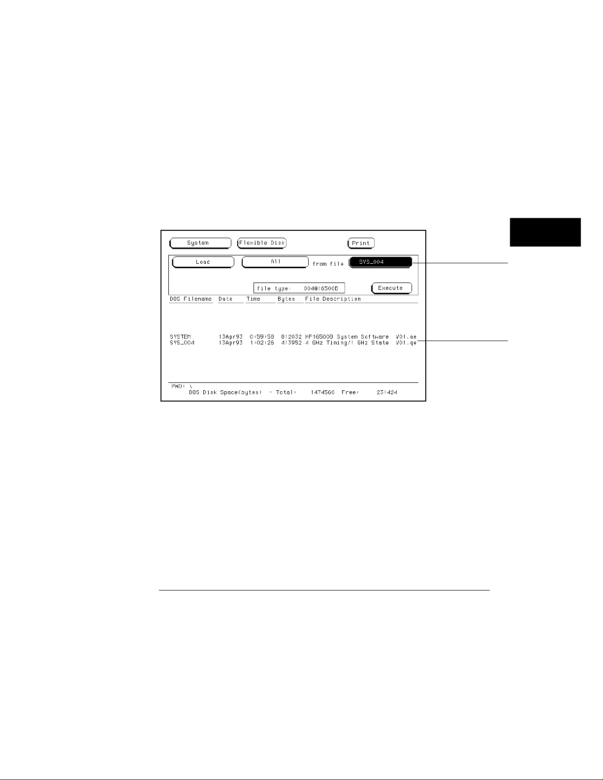
Loading a File
The Lo ad oper at ion al low s you to load pr e stored conf igur ation files . Use th is
operat ion when you want to quickly restore th e analyz er to a conf igur ation
used in a previous m eas ur em ent or co ndition.
Insert the s ource disk into the disk drive.
1
2 Select the Load operation.
When the Load sel ection is made, the anal yz er reads th e disk directory and
displ ays a list of all files on th e disk.
Select the File type field.
3
File type field
File Type Parameter Field
5–8
The Disk Drive Menus
Loading a File
4 From the pop-up that appear s, sel ect the des ired file type.
The System choi ce loads things like interface (R S-23 2C /HP-IB) and
inte rm odule conf igur ations, and de faul ts from the Utilities m enu.
The Module choice loads m eas ur em ent m odule conf igurat ions and data.
The All choice loads both Sys tem and m odule conf igur ations and da ta files .
Select the de sired file nam e from the list by ro tating the knob. As the
5
knob is ro tated, the file na m es are ro lled into the Filenam e field.
The two spaces(_ _) af ter the filenam e designat es th at this file is for th e
system . One space and a let ter (f or exam ple, "_A") af ter the filenam e
designat es that the file is for th e m eas ur em ent m odule in sl ot A.
Filename field
Filename Selection
7 Select the Execute field.
The disk dr ive indicat or light illum ina tes as the file is being loa ded.
Scroll bar
5–9

The Disk Drive Menus
Formatting a Disk
Form atting a Disk
The Form at oper at ion initializes new flexible disks for use in the anal yz er as
well as refor m ats the ha rd drive. The anal yzer will form at double-si ded,
double density or high density flexible disks in both LIF and DOS for m at s .
The anal yzer doe s not s uppo rt si ngle-si ded for m ats.
The logic analyzer does not s uppo rt track sparing during for m at ting. If a bad
t r ack is found, th e disk is considered ba d. If a disk has been for m atted
els ew her e with t r ack spari ng , it will be r ead successfully.
To for m at a flexi ble disk, perfor m the following steps:
Insert the flexible disk to for m at into the disk drive.
1
2 Select the Format Disk ope ration.
When the Form at select ion is made, the disk dire ctor y is displ ayed. The
UNSUPPORTED FORM AT m ess age appear s if th e disk is a new unform atte d
disk. This is norm al, cont i nue the for m at oper a tion.
Select the Format type field, and toggle to eithe r the LIF or DOS.
3
The anal yzer r ecognizes a variet y of sector si zes for LIF disks. H ow ever,
when for m atting LIF disks, th e anal yz er only creat es 1024 byte sectors.
When for m at ting DOS disks, the anal yz er cr eates 512 byte sectors .
LIF or DOS Format Selection
5–10
Format type field

The Disk Drive Menus
Formatting a Disk
CAUTION BEFORE YOU CON TIN UE, be sure y ou ar e in the FLEXIBLE DISK
m enu. Since you can form at both the flexible and ha rd disks, you alw ays
s hould be sure as to which disk m enu you ar e in.
CAUTION O nce the form at operation is execut ed, all files ar e per m anent ly er as ed from
the disk be ing form atted. This includes the HARD DISK. Ther e is no way
to retri eve the original inform ation fro m a form atted disk.
Select the Execute field, the n sel ect Continue.
4
5–11

The Disk Drive Menus
Storing Files on a Disk
Storing Files on a Disk
The Store operation allow s you to s t or e instrum ent conf igurat ions and
m eas ur em ent data. Use this oper a tion when you want to save the pres ent
analyz er setup for r ecalling at a lat er time. When conf igur ations are st ored to
disk, you ar e given the option to store System only, m odule only, or All
(System and m odule).
If y ou ar e st oring to a flexi ble disk, ins e rt the de stination disk into the
1
flexible disk drive.
2 Select the Store operation.
When the Stor e sel ect i on is made, th e analyz er r eads the disk dir ect or y and
displ ays a list of all files on th e disk.
Select the File type field.
3
File type field
File Type Parameter Field
4 From the pop-up that appear s, sel ect the des ired file type.
The System choi ce loads interface (R S-23 2C a nd HP-IB) a nd inte rm odule
conf igur ations , a nd defaults fro m th e Utilities m enu.
The Module choice loads m eas ur em ent m odule conf igurat ions and data.
The All choice loads both Sys tem and m odule conf igur ations and da ta files .
5–12

The Disk Drive Menus
Storing Files on a Disk
5 If you are st oring to a ne w nam e, sel ect the "to file" field and type in
the new nam e .
The filenam e must st art with a lette r and may cont ain up to eight char act er s.
It can be any com bination of letters a nd num bers, but there can be no blank
spaces betw een any of the charact ers.
If you are stori ng to an existi ng file na m e, si mply turn the knob to scroll
existing file nam e s throug h the field.
to file: field
File Name Field
When perfor m ing disk oper ations , th e path and disk capacity infor m ation
locat ed at the bottom of the m enu will be he lpful.
DOS Form ats
PWD:\ is the pr es ent working dir ector y from which th e files ar e cont ained.
Total: is the total memory capaci ty (bytes) of the flexible or hard disk.
Free: is th e total memory capaci ty (byt es) re m aining.
LIF Form ats
Total: is the total memory capaci ty (bl ocks) of the flexible disk.
Free: is th e total memory capaci ty (bl ocks ) rem aining .
Largest: is the si ze of the lar ges t block rem aining.
5–13

File description:
field
The Disk Drive Menus
Storing Files on a Disk
6 Select the "file de scription" fiel d and us ing the pop-up keypad, type in
a description of the file.
A file description can cont ai n up to 32 character s, but also can be left blank.
This field is for your conveni ence to m ake it eas ier for ide ntifyi ng the type of
da ta in each file.
File Description Field
5–14

The Disk Drive Menus
Renaming a File
Renam ing a File
The Rename oper ation allow s you to give a new nam e to a previously stored
file. The only restrict ion is that you ca nno t renam e a file to an alread y
existing filenam e.
Select the Rename oper ation.
1
2 Turn the knob until the file na m e you want to renam e is scrol led into
the file field.
File field
Type field
File Field
3 Select the file Type field. From the pop-up that appear s , sel ect the
desired type sel ect ion.
The All sel ect ion allow s you to ren am e both the system and m odule types.
The Module sel ect ion allow s only th e m odule file type to be renam ed.
5–15

New file name
field
The Disk Drive Menus
Renaming a File
4 Select the new file nam e field.
New File name Field
5 Using the pop-up keypad, type in the ne w filenam e , then sel ect Done.
5–16

The Disk Drive Menus
Autoloading a File
Autoloading a File
The Autoload oper ation al low s you to de signat e a set of conf igurat ion files to
be loaded aut om atical ly the next time th e ins tru m en t is tu rn ed on. This
allow s you to change the de fault conf igur ation of cer t ai n m e nus to a
conf igur ation that be tter fits your nee ds.
Select the Autoload oper ation.
1
2 Select the Enable/Disable field then sel ec t Enable.
3 Turn the knob until the file na m e you want to aut oload is scrol led
into the file na m e pa ra m eter fiel d.
Enable/Disable field
Autoload File name Parameter Field
5–17

The Disk Drive Menus
Autoloading a File
4 Select the Execute field.
An aut oload file is cr eat ed and placed at the top of the list of files . The file
description cont ains the file nam e to be aut oloa de d a nd indicat es whether or
not the Autoload oper ation is enabled.
File name
parameter field
Autoload File name Field
The Autoload oper ation loads all files for a given file nam e. If you want to
load only the file for a type, ren am e th at file to separate it fro m th e other files
a nd enable it as the cu rren t Autoloa d file.
As long as Autoloa d is enabled befor e the instr um ent is shut off, Autoload will
rem ain enabled when you powerup the instr um ent and load th e conf igurat ion
files .
5–18

File field
The Disk Drive Menus
Purging a File
Purging a File
The Purge operation al low s you to delete a file fro m th e list of file na m es.
The file type can be either the M odule typ e or All typ e.
Select the Purge oper ation.
1
2 Turn the knob to scrol l the file nam e to be pur ged into the "file" field.
File type field
File Field
3 Select the file "type" field, then sel ect the file type to purge .
The All sel ect ion allow s you to purge both the system and m odule typ e s.
The Module sel ect ion allow s only th e anal yz er type to be purged.
Select the Execute field, the n sel ect Continue.
4
5–19

The Disk Drive Menus
Copying a File
Copying a File
The Copy oper at ion al low s you to m ake a duplicat e copy of an existi ng file on
th e sam e disk or a differ ent disk. If you copy the file to th e sam e disk, the
only restrict ion is that you must give the copi ed file a new nam e. Yo u can
speci fy to copy All types or just th e Module part of a file.
Select the Copy oper at ion.
1
2 Turn the knob until the file na m e you want to copy is scrol led into the
"file" fiel d.
File field
Type field
Copy Filename Parameter Field
3 Select the "type" fiel d, then sel ect the des ired file type.
The All sel ect ion allow s you to copy bo th the system and m odule parts of a
conf igur ation file set.
The Module sel ect ion allow s only th e m odule part to be copied.
5–20

New file name
field
The Disk Drive Menus
Copying a File
4 Select the new file nam e field, then from the pop-up keypad that
appear s, ent er the ne w file nam e in one of two ways:
If you want to keep the old nam e, simply sel ect CLEAR, th en the DONE field
•
from the keypad. The old nam e is tran sferred aut om a tically.
If you want a ne w nam e, typ e in the ne w na m e, th en sel ect DONE.
•
New filename Field
5 Select the Execute field.
5–21

The Disk Drive Menus
Packing a Disk
Packing a Disk
By pur ging files fro m th e disk and a dding other files, you may e nd up with
blank ar eas on the disk (bet ween files) th at ar e too sm all for the ne w files
you are creat ing. On LIF disks, the Pack Disk oper at i on packs the cu rrent
files toge ther, rem oving unused ar eas from betw een the files so that more
space is available for files at the end of the disk.
Select the Pack Disk operation.
1
2 Select the Execute fiel d, then sel ect Continue.
Execute field
Pack Disk Operation
5–22

The Disk Drive Menus
Duplicating a Disk
Duplicating a Disk
The Duplicat e Disk oper ation copi es the vol um e label s and directories from
one disk to anot her . If th e new disk is not for m at ted , th is oper at ion also
for m ats th e disk. This oper at i on allow s you to m ake a backup copy of your
important disks so you won’t los e important da ta in the event th at a disk
wears out, is dam ag e d, or a file is acci de ntly deleted.
Select the Duplicate Disk operation.
1
2 Select the Execute field, the n sel ect Continue.
Execute field
CAUTION
The Duplicate Disk Operation
3 When “Insert DESTINATION disk” appear s , inse rt the destina tion
disk into the disk drive. When "Insert SOURCE disk” appear s ,
rem o ve the destina tion disk a nd reinstall the sour ce disk.
The num ber of times you nee d to change the disks depends on whether you
have a double-density or high- density disk. Simply follow the ins truc tions
a nd sel ect Continue to cont inue .
The original dir ectory and files on the de stination disk are des tr oyed by the
Duplicate Disk opera tion.
5–23

The Disk Drive Menus
Making a Directory
Making a Dir ectory
1 Select the Make Directory operation.
2 Select the directory na m e field a nd us ing the pop-up keypad or
key boa rd, type in the new directory na m e .
3 Select Execute, then sel ect Continue.
Make Directory
5–24

The Disk Drive Menus
Changing the Directory
Changing the Dir ect ory
1 Select the Change Directory operation.
2 Select the directory na m e field. Using the pop-up keypad or
key boa rd, type in the new directory na m e .
3 Select Execute.
Change Directory
When perfor m ing disk oper ations , th e path and disk capacity infor m ation
locat ed at the bottom of the m enu will be he lpful.
DOS Form ats
PWD:\ is the pr es ent working dir ector y from which th e files ar e cont ained.
Total: is the total memory capaci ty (bytes) of the flexible or hard disk.
Free: is th e total memory capaci ty (byt es) re m aining.
LIF Form ats
Total: is the total memory capaci ty (bl ocks) of the flexible disk.
Free: is th e total memory capaci ty (bl ocks ) rem aining .
Largest: is the si ze of the lar ges t block rem aining.
5–25

The Disk Drive Menus
Creating a System Flexible Disk
Cr eating a System Flexible Disk
Location of th e System Files
When the logic analysis system is conf igur ed at Hewlet t -Packar d with the
a ppropriat e m odules, the system files for th e mainfram e and individual
m odules were loa ded onto the hard disk drive in the subdi r ector y called
"SYSTEM ". It is rec om m ended that if new m odules are a dde d or any system
file re visi ons occur, th ey be loade d onto the hard disk drive in this
subd i rectory.
H ow ever, if you want system files on a flexible disk, us e th e appropriat e disk
operat ions, such as st ore or copy, to stor e all req u ired system files on a
flexible disk.
What Files ar e Required on a System Disk?
A system disk consists of th e sof tware require d to opera t e the mainfram e and
each m odule in the system . For the mainfram e, th is is th e file SYSTEM _ of
th e file typ e 16500B_s ys t em . For th e individua l m odules , it is th e file
SYS_XXX of th e file typ e XXXXXX_system. The th ree charact er s (XXX) in
th e filenam e r epr es ent the identificat ion code for each indivi dual m odule.
The si x charact er s (XXXXXX) in the file type r epr esent the produc t model
num ber for each m odule.
What is a system perform ance ver ificat i on disk?
A system perform ance ver ificat ion disk is a disk th at cont ains all the
perfor m ance verificat ion software required to run th e perform ance
ver i ficat i on tests for th e HP 1650 0B Logic Analysis System and the
correspon d ing m odules conf igur ed in th e system . This com posite disk is
found in each software pouc h. For more infor m ation on th e perfor m anc e
ver i ficat i on tests, refer to the
All system perfor m ance ver ificat ion files are s t ored on th e hard disk in th e
/SYSTEM subdi rectory.
5–26
HP 16500B Servi ce Guide
.

6
The System Utilities Menu

The Sy stem Utilities Menu
The Sy stem Utilities menu is one of the menus within the System
module. The m enu is use d for turning the sound on and off,
r ecalibra ting the touchsc r een, setting the clock, and changing the
default ins tru m en t col ors .
A ccessing the System Utilities Menu
In the upper-left cor ner of the screen ar e two fields that indicat e
which module, and which m enu within that m odule you ar e in.
If the Module field in the uppe r-left cor ner doesn’t displ ay Sy stem ,
sel ect this field and when the pop-up appear s, sel ect
bring up one of the System menus.
O nce in the Sy stem m odule, if the M enu field doesn’t displ ay Utilities ,
sel ect this field. When the pop-up appears , sel ect
the System Utilities menu.
La yout of the System Utilities M enu:
System. This will
Utilities to br ing up
Touch calibration
field
Color adjustment
fields
Module field Menu field
The System Utilities Menu
6–2
Clock adjustment field
Sound on/off
Current display colors

The System Utilities Menu
Menu Map
The follow ing menu map illus trates all fields a nd availabl e options in
the Utilities menu. The menu map will help you get an overview as
well as provide you with a quick refer ence of what the Utilities menu
cont ains .
System Utilities Menu Map
6–3

The Touch and Sound Fields
This sect ion cover s the Touch a nd So und fiel ds of the Sys tem Utilities
menu. Thes e fields allow you to r ecalibr ate the touchs creen for better
line-of-si ght us e and turn on and off the s ound of the instru m ent.
Touch Calibration
It is unnec e ss a ry to pe riodically calibrate th e touchscree n. Touch calibr a tion
just allow s you to reset the touchs cr een to your needs a nd com pensat e for
pa rallax from differ ent view ing angl es .
The Touch Calibr a tion field in the upper-left corner of the display br ing s up
th e pop-up for adjusting the touchs cr een calibr a tion to your own line of si ght
a nd to the angle at which you touc h th e screen.
Touch Calibration
field
Selecting Touch Calibration
6–4

The System Utilities Menu
Touch Calibration
The default calibration is accept able for most uses, but to change the
calibration do the follow ing:
Select the Touch Calibration field.
1
2 Select the A field as accur ately as pos sible.
3 Select the B field as accur atel y as possi ble.
Recal ibra tion is do ne immediat ely af ter you touch A or B. The point at which
you rem ove your finger from A or B deter m ine s where you place your finger
to act ivat e s ub seq uent fields .
Select Done when you ar e finished.
4
To return to th e defaul t Touch calibr a tion, select the Touch Calibration field
a nd when th e pop-up appears , sel ect the Default field. This returns th e
instru m en t to its default touchs cree n calibr a tion. Select Done when you ar e
finished.
At po we r-up, touch retu rn s to the default calibration, unless a cust om ized
HP 1650 0B conf igur ation file is loaded as pa rt of an aut oload sequence .
Touch Calibration Pop-up
Touch On/Off
To tur n the Touch func tion of f, press the Touch Disable but ton on th e fron t
pa ne l.
6–5

The System Utilities Menu
Setting the Real-time Clock
Se tting the Real-time Cloc k
For doc um entat ion purpos e s, a r eal -time clock read o u t appe a rs in th e displ ay
m enus. To adjus t the real-time clock , si mply sel ect the Real Time Clock
Adjustments field, th e n sel ect the da te or time elem ent des ired fro m th e
pop-up m enu show n below. Use the knob to set num bers a nd the ke yboa r d
or touchscree n to sel ect th e corr ect m onth. When you ar e finished, select
Done.
Real-time Clock Pop-up
6–6

The System Utilities Menu
Turning the Sound On/Off
Turning the Sound On/Off
In the uppe r-right cor ner, below the Print field, is th e So und On field. This
field is us e d to tu rn the ins trum ent’s s ound on a nd off. These inc lude the
clicks you hear when you select fiel ds on the m enus and the beeps you hea r
on error m es s ages.
To tur n off the s o und, sel ect Sound On a nd it changes to Sound Off, s hutting
off the s ound. To tu rn them on again, sel ect Sound Off a nd it changes back
to Sound On, turning the sound on again.
The Sound On Field
6–7

Displ ay Color Se lection
In the HP 16500B, color s aves time a nd prevent s errors by clar ifying
the displ ay, making it easier to distinguish one major area from
anot her.
The color sel ection featur e of the HP 16500 B allow s you to cust om ize
displ ay col or s , which improves cont rast and les sens eye fat igue caused
by your operating environm ent. If you ar e color- blind to cer t ai n
col ors, are oper a ting in a difficult light environ m ent, or don’t like the
default color s , you can quickly and easily change them .
The Color M odel
The HP 16500B use s th e H SL color model (H ue, Saturation, a nd Lum inosity) .
This model is ver y ef fective for inter act i ve color sel ect i on. Similar in concept
to the method use d by ar t i st s for mixing pa ints , pur e hues ar e sel ected, and
th en white and black ar e mixed to dilute the col or or dar ken it.
Hue is th e pure color . 0 is re d , 33 gr een, and 67 blue. The sel ect ion
•
ran ges from 0 to 100.
Sa tura tion is the ratio of th e pure col or mixed with white (0 to 100% )
•
Lum inos ity is the br ightness pe r unit area (0 to 100% ).
•
The figure on th e nex t page show s a cyl indrical r epr esentation of the HSL
model (H ue, Sa tur ation, a nd Lum inosity ). Hue is the angul ar coordi nate,
Sa tura tion is the rad ial coordinate, a nd Luminosity is th e altitude above the
polar coor di nate plane.
The cylinde r rests on a black plane (Lum i nos ity = 0% ) and ex te nds upw ard.
As you increase in altitude, you increas e lum inos ity, which r epr es ents an
inc rea se in brightness. W henever lum inosity is zero, the values of saturation
a nd hue do not matter . Zero lum inos ity is black, and 100% lum inos ity gives
you th e pure color .
6–8

The System Utilities Menu
Turning the Sound On/Off
White is th e cent er of th e to p of the cylinder (Lum inosity = 100% , Sa tur ation
= 0% ) . The cent er line of the cyl inder (Sat uration = 0% ) is a line which
connect s the cent er of the black plane (Lum i nos ity = 0% , Saturation = 0% )
with white (Lum i nosity = 100% , Saturation = 0% ) through a seri es of gr ay
steps (Lum i nosity from 0% to 100% , Satur ation = 0% ) . W henever saturation
is 0% , the val ue of hue does not matter . Zero satur ation is white, and 100%
saturation gives you the pure color . The out er edge of the cylinde r
(Saturation = 100% ) r epr esent s the fully saturated color .
The Color Model
6–9

The System Utilities Menu
Selecting the Color, Hue, Saturation, and Luminosity Fields
Se lect ing the Color, Hue, Sa turation, and Lum inosity
Fields
To select the Color, Hue, Sa turation, or Lum inosity fields, s ee if the fiel d you
want has a differ ent background than the other fields (l ight blue for the
default colors) . If it alr eady has a differ ent b a c k g round, rotat e th e knob to
change th e value in th at fiel d. Othe rw ise, select the field once and its
ba c k g round will change col or, indicat ing that it has been select ed. Then
rotat e th e knob to change the value. If you look at the lar ge field in th e
cent er of th e displ ay, you can s ee how the knob af fect s the color .
If you know the value you want in a particul ar field, see if th at field has a
differe nt ba c k g round th an the other fields (l ight blue for the de fault col ors).
If it alr eady ha s a differ ent bac k g round, sel ect th is field a nd a pop-up keypad
will a ppe a r. Otherwise, sel ect the field once to sel ect it and a se cond time to
bring up th e po p-up keypad. Then ent er th e value you want with the keypad
a nd sel ect Done. The po p-up will disa ppear, placing your new val ue in the
a ppropriat e field a nd changing the color.
Color Selection
6–10

Selecting the Color, Hue, Saturation, and Luminosity Fields
Example Use the knob to change the value of Hue to 45.
Select the Hue field once .
1
2 When the bac kg round of the Hue field changes color (light blue for
default colors ), turn the knob to change the va lue for Hue to 45. You
can s ee how the knob affect s the color in the lar ge field at the cent er
of the displ ay.
The System Utilities Menu
Changing the Value for Hue
6–11

The System Utilities Menu
Selecting Colors
Example Use the pop-up keypad to change the value of Lum inosity to 65.
Select the Luminosity field once and its ba c kg round changes color
1
(light blue for default colors ).
2 Select the Luminosity field a s e cond time and a pop-up keypad
appear s.
3 Enter 65 with the keypad and notice that your val ue appear s in the
box at the top of the keypad.
4 When y ou ar e finished, sel ect Done a nd the pop-up keypad will
disappear , placing y our value in the a ppropriat e fiel d and changing
the color .
Changing the Value for Luminosity
Se lect ing Colors
Once the Color field has been sel ect ed, you can select any one of seven
var i able disp l ay colors by rotat ing the knob on th e fron t pane l. The Color
field displ ays your choice (1 thr o ug h 7) . The lar ge fiel d to the right of the
Color field displ ays th e color you ar e working with, a nd the sm al l num bered
fields within this lar ge field displ ay the other col or s avai lable. The table on
th e next page list s the displ ay col ors for th e HP 1650 0B.
The screen m ay be turned of f when using an ext er nal cont roller by setting
th e Lum inosity of each color to zero.
6–12

The System Utilities Menu
Selecting Colors
HP 16500B Display Colors
Color Default Color Hue Saturation Luminosity Uses
1 Tan 13 43% 76% Main background color for the display
2 White 0 0% 100% Light text and timing waveforms on certain
modules
3 Dark Blue 60 100% 60% For touch items (touch-sensitive fields)
4 Light Blue 60 45% 90% For selected items, items that the knob is
assigned to, limited background use, and
certain display channels on the oscilloscope
module
5 Green 33 100% 75% For the Run field, advisory fields, the X marker
on certain modules, certain display channels
for the oscilloscope module, and
miscellaneous other uses
6 Red 0 100% 100 For the Stop field, error fields, the Cancel
7 Yellow 15 100% 100% For warning or advisory fields, the O marker
0* Black — — 0% For dark text, background, and waveform
Print field, the trigger point, and certain
display channels on the oscilloscope module
on certain modules, certain display channels
on the oscilloscope module, and
miscellaneous other uses
areas
* Color “0 " is a non-var iable col or.
6–13

The System Utilities Menu
Returning to the Default Colors
Returning to the Default Colors
The Defaul t Colors field, below the Lum inosity field, allows you to return to
th e default col ors si mply by sel ect i ng th at field. These de fault color s ar e
listed in the table on th e previous page.
6–14

7
Inte rm odule M easur em ent s

Inter m odule M eas ur em ents
The HP 16500 B can be conf igur ed with several differ ent m odules
inside the ins tru m en t at one time. The Inter m odule m enu allow s you
to make inter act ive m eas ur em ent s be tween the se modules. As an
exam ple, you would us e the ac quisition capabi lities of one module to
look at a si gnal, while us ing the trigger ing capabilities of anot her
module to properly trigger the m eas urem ent .
When m odules are conf igur ed in the Inter m odule menu, you also have
the capability to disp lay the resulting w avef orm s and stat e listings
from several modules toget he r in the sam e disp lay m enu.
The ba s ic func tions of the Inter m odule menu are:
• Configur e m odules to ru n si multaneously or in an ar m ing sequence
betw een m odules .
• Sync hronize with ext er nal equipm ent.
• Adjust s kew betw een m odules .
Configuring Arm ing Sequences
You sel ect m odules to run either inde pe ndently or within an
interm odule conf igur ation. As you m ake m odule select ions , a
conf igur ation tr ee beg ins to form . In a ddition, an ar m i ng or der for m s
depe nde nt on the order in which you sel ect the modules.
Within the conf igura t ion tr ee, modules tha t ar e connect ed dire ctly to
the lar ge
execut ed. M odules tha t appear connect ed below ot he r modules ar e
ar m ed when the prec e ding m odule finds its trigger .
7–2
Group Run field ar e ar m ed immediat ely af ter a Group Run is

Intermodule Measurements
Synchronizi ng with External Equipm ent
O nce a m odule is a dde d to the conf igura t ion tr ee, the POR T OUT
si gnal can be adde d beneat h that module or any other module, which
sends an ar m ing si gnal out to a BNC connect or on the rear pane l.
The PORT IN si gnal can be sel ect ed to ar m the interm odule
conf igur ation in conjunc tion with the Group Run/Stop field. You can
qua lify the PO RT IN si gnal by de fining level a nd edge criter ia.
Adjusting Skew betw ee n Modules
You can modify the skew or timing de v iat ion between the m odules
within the inter m odule m ea s ur em ent . This allows you to com pensat e
for any know n delay of the system under tes t or com pare two signals
by rem oving any displ ayed skew between the si gnals.
Skew
Run/Arming order
Synchronize to external
equipment
The Intermodule Menu
7–3

Intermodule Measurements
Menu Map
The follow ing menu map illus trates all fields a nd availabl e options in
the Inte rm odule m enu. The m enu map will help you get an over view
as well as prov ide you with a quick refer ence of what the Inter m odule
menu cont ains .
Intermodule Menu Map
7–4

Module field
Intermodule selection
Intermodule Measurements
Accessing the Intermodule Menu
Access ing the Interm odule Menu
To br ing up the Interm odule m enu, sel ect the m odule field in the upper-left
corner of any m enu. When th e sel ect i on pop-up appears, sel ect th e
Intermodule field to bring up the Interm odule m e nu.
Accessing the Intermodule Menu
With only one m eas ur em ent m odule loa ded into the system , inte rm odule
m eas ur em ent s ar e not possi ble, so, the Interm odule m enu is not availabl e. If
you have an HP 16501A Expansion Fram e connected, m odules loa de d into
th e expa nsion fram e are available for an interm odule m eas ur em ent .
7–5

Group run field
Intermodule Measurements
Configuring a Group Run
Configur ing a G roup Run
When the Group Run field is sel ect ed, it toggles betw ee n two choi ces which
sets how the interm odule m easur em ent is ar m ed.
Group Run This sel ect ion start s the interm odule m eas ur em ent when
you sel ect th e G r o up Run field in any of th e m odule m enus. This field is
also the Run field, but when you have an interm odule m eas urem ent
conf igur ed, the Run field changes to Gr o up Run. Yo u st ill have the
choice to r un th e group in Single or Repetitive ac quisi tion mode.
Group Run Arm ed fro m PORT IN
This select ion star t s th e interm odule m easurem ent when an exter nal trigger
source, matching the trigger level and edge re qu irem en ts you set, is s een at
th e PO RT IN BN C connect or on the rear pane l.
Group Run/Stop field
Group Run Field
7–6

Intermodule Measurements
Configuring a Group Run
Example The following exam pl e illus trates what happens when you execute a Group
Run. For this exam pl e we use the interm odule conf igur ation show n in the
figur e below .
Group Run/Stop field
Status indicator
When you sel ect th e Group Run field, the follow ing event s occur :
The st at us indicat or of each m odule involved changes fro m Stopped
1
to Running.
2 The prestor e and trigger qualification st at us of m odule B (analyz er )
and m odule D (oscillos c ope ) is checked.
3 When prestore and trigger qualificat ion of m odules B a nd D ar e met,
module C is ar m ed a nd its appropr iate m easur em ent is run .
4 Module C trigger s, and si multaneously ar m s m odules B and D.
5 Module D trigger s, and sends a signal to an ext ernal device throug h
“P O ” (P O R T OUT).
6 The st at us of each module changes to Stopped when the m odule
finishes its ope rations . After all the m odules ar e finished, the data is
displ ayed in the individua l displ ay menus of the m odules.
If the m odules ar e time co rrelat ed, the time correlation bars at the botto m of
th e m enu displ ay the start and stop acquisi tion windo w of each m odule
relat ive to the other m odules.
7–7

Intermodule Measurements
Configuring Port In/Out
Configur ing Port In/Out
The PORT IN/OUT fiel d acces ses a conf igur ation m enu which is used to
conf igur e which m odule an ext er nal ar m i ng si gnal (P O R T OUT) is sent from .
Also, from th is m enu you define vol tage level a nd edge cr iteria th at must be
matched by any inc o m ing ar m ing si gnal (PO R T IN) befor e the interm odule
m eas ur em ent can beg in. The PO RT IN/OUT field is show n below.
PORT IN/OUT field
PORT IN/OUT Field
PORT OUT
PORT OUT is us e d to enabl e an ext er nal dev ice from anot her m odule in the
inte rm odule conf igur ation tre e. To conf igur e a PORT OUT signal, do th e
follow ing:
Select the PORT IN/OUT field above the module field, the n sel ect the
1
PORT OUT field fro m the POR T IN/OUT Se tup m enu that appear s .
2 From the sel ect ion list c hoos e the m odule you want the si gnal to
com e from .
The sel ect ion list will contain th e nam es of all the m odules conf igur ed in th e
gr oup run. A "PO" indicat or will appea r in the conf igur ation tree originating
from th e m odule you select .
7–8

Intermodule Measurements
Configuring Port In/Out
The PORT OUT signal is a positive- going TTL pulse whose width varies
depe nding on th e m odule that is drivi ng it. The po rt may be ter m inated by a
50 Ω load to r e duce ringing, how ever , the si gnal will th en be less than or
equal to 0.4 V when low a nd at leas t 2.0 V when high.
PORT IN
With a trigger si gnal connect ed to th e PORT IN BN C on the rear pa nel, th e
inte rm odule m eas ur em ent can be star t ed with th is si gnal after preset voltag e
a nd edge cr i ter ia is met. To conf igure a PORT IN si gnal , do the follow ing:
Select the PORT IN Level field and set the level to TTL, ECL, or a User
1
defined level be tween +5 V and −4 V.
2 Select the PORT IN Edge field and tog gle the edge type to either Risi ng
or Falling.
3 After the PORT IN voltage level and edge criter ia is set, sel ect the
Group Run/Stop field. The analyzer will wait until the pr ope r si gnal is
s een at the PORT IN BNC be for e the m easur em ent be gins .
PORT IN/OUT Setup Menu
Only the HP 16500B has the PORT IN BN C . However, th e PORT IN si gnal is
availabl e to m odules in both the HP 16500B and HP 16501A fram es.
When us ing PORT IN, an ext er nal devi ce must be connect ed to the PORT IN
BNC on th e rear pane l. If an ext e r nal device isn ’ t connect ed, or is accidently
dis c o nne cted, the ins trum ent will not trigger.
7–9

Intermodule Measurements
The Group Run/Stop Field
The G roup Run/Stop Field
When a m odule is adde d to the interm odule conf igur ation tr ee, th at m odule’s
Run/Stop field changes to the Group Run/Stop field. A Gr o up Run/Stop field
is also avai lable in the Interm odule m enu. This field starts an acqui si tion just
like any individual m odule’s Group Run/Stop field. When an acqui si tion is
start ed in the interm odule m enu, you can monito r the resu lts with the
Running/Stopped status indicator s and time-correlat ion bars.
When you sel ect th e Group Run/Stop field, a pop-up appears with two choices
for a c quiring da ta.
Single, which is th e default, al low s you to run the m easurem ent once.
•
Repetitive allows you to run the m easur em ent as many times as you want
•
to col lect data for statisti cal m eas ur em ent s, et c. Press Stop when you
want to st op a rep e titive run.
Group Run/Stop Field
Group Run/Stop field
Run mode selection
7–10

Intermodule Measurements
The Modules List
The M odules List
On th e right si de of th e screen are fields listing the differ ent m odules th at can
be conf igur ed in the Interm odule m enu. When you sel ect one of the m odule
fields , a pop-up appe a rs displ aying the possible locat ions of the m odule in the
inte rm odule conf igur ation tre e.
Indepe nde nt allows th e m odule to r un independe ntly of th e othe r m odules
•
a nd r em oves it from the interm odule conf igurat ion tr ee.
Group Run places the m odule directly below th e lar ge Gr o up Run
•
Configura t ion field. This m odule is arm ed immediately af ter the Group
Run/Stop field is touc he d.
The ot her fields in the pop-up list th e na m e of the m odules that ar e
•
alr eady pa rt of th e interm odule conf igur ation tre e, a nd can be us e d to ar m
this m odule. Selecting one of thes e fields places th e cu rren t m odule below
the m odule indicat ed by the field you select ed. The cu rre n t m odule is
then ar m ed when the prec e ding m odule finds its trigger .
After you m ake your select ion, a box a ppears in th e interm o dule
conf igur ation tr ee with the m odule’s sl ot locat ion (A throug h E for th e HP
16500B alone, or A thr o ug h J for the HP 16500B with th e HP 16501A
at t ached) r epr es ent ing the locat ion of the m odule in the tr ee.
The Module Pop-up Menu
7–11

Intermodule Measurements
Status Indicators and Time Correlation Bars
Status Indicators and Time Correlation Bars
The m essage "Running" or "Stopped" appe ars below th e nam es of the
individua l m o dules th at ar e listed on the right si de of the Interm odule m enu.
This indicat es the cu rren t st at us for each m odule and can be us e d to monitor
th e interm odule m eas ur em ent . If there is a pr oblem with th e m eas ur em ent , a
quick check of these status indicat or s can show you which m odules have
com pl eted their oper at ions (St oppe d) a nd which ones ar e st ill Running.
Generally:
If a m odule was running and is stopped now , you can as sum e it r eceived
•
its ar m i ng si gnal a nd trigger ed prope rly.
If a m odule locat ed below a st opped m odule on th e interm o dule
•
conf igur ation tre e ha s received an ar m ing si gnal and is still r unning , it is
still looking to sati sf y it’s trigger sp eci ficat ion.
If a m odule below a running m odule on the interm odule conf igurat ion tree
•
ha s not received its ar m ing si gnal, it will not begin running.
The time corre lat i on bars at the botto m of the m e nu displ ay the start and
stop time of each m odule relat ive to th e other m odules .
Status Indicators/Time Correlation Bars
7–12
Status Indicator
Time correlation bars

Intermodule Measurements
Adjusting Skew
Adjus ting Skew
Select ing th e Skew field br ings up th e Inte rm odule Skew m enu.
The Interm odule Skew m enu is us e d to s kew w avef or m s or state listi ng s
betw ee n m odules on th e displ ay. This al low s for display adju stm en t to within
2 ns betw een m odules. The major purpos e of this adju stm en t is to
com pensat e for variances in internal pr obing delays acr oss m odules.
To adjust th e skew of th e m odule, select the individual m odule within the
Ske w m enu a nd a dd or subt r act a know n time value. This val ue may be
calculat ed with the markers by m easuring th e skew betw een som e com m on
si gnal sam p l ed by both m odules .
The Skew Pop-up
7–13

Intermodule Measurements
What Are Some Typical Intermodule Measurements?
What Are Som e Typical Inter m odule M eas ur em ent s?
Interm odule m easurem ents may be as si mple as start ing sever al m odules at
once, or very com plex with multiple ar m ing sequences betw een m odules and
ext er nal equipm ent. Som e exam pl es are:
Example Analyzing a Glitch
A glitch is defined as two or more tran sitions betw een the sam ples of a timing
analyz er that cr oss th e logic thres ho ld. A timing anal yzer can trigger on a
glitch a nd capt ur e it, but doesn’t have the vol t age or timing resolution to look
at th e glitch in detail. On th e ot he r hand, an oscillos cope can acqui re
w avef or m s with a gr eat deal of reso lution, but it can’t trigger on glitches,
com binations of glitch e s, or patte rn s.
To analyze a glitch , use a timing anal yz er and an os cilloscope inter act ivel y.
Set up the timing anal yz er to trigger on a glitch and when the timing anal yz er
triggers , capt ure the glitch with th e os cilloscope. Then us e the os cillos c ope
to look at the w avef or m param eters of th e glitch, including its width, s hape,
a nd am plitude .
For this inte rm odule m easurem ent, you ar e using the trigger ing capabi lities
of the timing analyz er and the acquisi tion capabi lities of th e os c illos cope.
Glitch Example
7–14

What Are Some Typical Intermodule Measurements?
Example Analyzing Interrupt Handling in a CPU System
Most micr opr ocess or pr ogr a m s can be interrupted by an as ynchronous
hard w are si gnal. Softw are designer s ar e inter ested in th e processor’ s
real-time resp o n se to interrupts. In particular , you need to answ er these
kinds of ques tions :
Does th e processor branch to the pr oper interrupt ha ndling rou tine?
•
Are r egisters and status infor m at ion saved pr oper ly?
•
How long doe s it t a ke to servi ce the interr upt?
•
Is the interrupt acknow ledged proper ly?
•
After the interr upt is servi ced, does the pr oces s or r es tor e registers and
•
status infor m at ion a nd cont inue with the previous rou tine as expect ed?
Usually, softw are designer s want to look at the pr ogr am flow of the
micr oprocess or system around an asynchr onous event .
A state anal yz er , c oupled with a prepr ocess or and an invers e as sem bl er , is
useful for t r aci ng th e flow of a micr oprocess or prog ram . A timing anal yz er or
an os cillosc ope is designed to trigger on asynchr onous event s like edges .
In this exam ple, use an os cilloscope with a sam pl e rate fast er th an the
micr oprocess or cl ock to trig ger on the asynchronous event and to ar m the
state anal yz er . Then us e the state anal yz er to check the a ddress of the
inte rrupt ro u tine. You may also us e the state anal yz er to see if the
micr oprocess or is properly servi cing interrupts and returning to th e cor rect
a ddress af ter each interrupt routine.
Intermodule Measurements
7–15

Intermodule Measurements
What Are Some Typical Intermodule Measurements?
Interrupt Handling Example
Set up the os cillos c ope to trigger on the as ynchronous interrupt line. This is
usually an e dge- sensitive line on which the oscillos cope can trigg er .
The st ate anal yz er shou ld be ar m ed by the os cillos cope. Set th e state
analyz er to trigger on all “d o n ’t cares ” and it will capt ure th e interrupt service
routine when the ar m signal is received. For this interm odule m easurem ent ,
ar m i ng th e st at e analyzer with the osc illosc ope allow s a sof t w are des igner to
t r ack the flow of a microprocess or pr ogr am around a hard w are interrupt.
Example A Simple Stimulus/R esponse System
During system devel opm ent , designer s ar e often faced with verifying a part of
a design when th e input si gnal s for that part ar e unavailabl e. Here ar e som e
com m on exam ples of this pr oblem :
Verifying h ard w are oper a tion when a part of the hard w are is unavailable to
•
drive th e ci rcuit.
Testing a PC board without a boa rd test system .
•
The trad itional sol ution is to us e word gener ator s to em ulat e the missi ng part
of the de sign, and to use logic anal yz er s and os c illos copes to capt ur e the
system response.
7–16

Intermodule Measurements
What Are Some Typical Intermodule Measurements?
Unfortunately, designer s ar e often faced with an aw kw ar d sol ution of
stacki ng sever al boxes on top of each ot her , with a maze of cabl es tying them
t ogether, a nd a different interface for each instrum ent.
The pa tte rn gener at or in the HP 16500B can act as the stack of word
gener at ors in th is pr oblem . Sta te, timing, and analog m odules can all be us e d
to capt ure the response of th e system .
The pa tte rn gener at or is loaded with the prope r patter ns and when it start s
sending pa tte rn s, it s e nds an ar m si gnal over the interm odule bus .
The acqui sition m odules ar e ar m ed from the pa ttern gener ator m odule and
set to trigger on th e appropriat e event in the system .
Stimulus/Response Example
7–17

Intermodule Measurements
Displaying Multiple Module Data on One Screen
Displ aying Multiple Module Data on One Scr een
When you ar e making interm odule m easurem ent s, you can displ ay th e
resu lting w avef or m s or stat e listi ngs for sever al m odules t ogether on one
screen. For exam ple, to displ ay w avef orm da ta for an oscilloscope and a
timing anal yz er on an osc illosc ope m enu, the proc e dure be low may be
follow ed. You m ay no t have th e exact sam e conf igur ation of m odules ,
how ever , the proce dure st eps will be similar .
Select the module field in the upper-lef t cor ner of the screen.
1
2 When the pop-up appears , sel ect the HP 16532A Oscilloscope m odule.
3 When the os c illos c ope m enu appears , sel ect the m enu in which you
want to view the da ta (for this exam ple,
4 Select the channel label field to the left of the w avefor m display once
to scrol l the w avef orm s. Se lect this field again to access the disp l ay
param eters .
Auto-Measure).
Selecting the Waveform Selection Pop-up
7–18

Intermodule Measurements
Displaying Multiple Module Data on One Screen
5 When the Waveform Selection pop-up appears , sel ect the field
displ aying
6 When the pop-up appears , sel ect State/Timing E. After the pop-up
Module Oscilloscope D.
disappears, the appropriat e labels for the channels of the HP 16550A
Stat e/Timing Analyz er will be list ed under the Stat e/ Timing E field.
Selecting State/Timing E
7–19
 Loading...