


Test Fixture
User’s Guide
AB CD E
HP Part No. 16442-90000
Printed in Japan August 1998
Edition 2
E0897

Product Warranty
Hewlett-Packard warrants Hewlett-Packard hardware, accessories and supplies against
defects in materials and workmanship for the period of one year from the warranty start
date specified below. If Hewlett-Packard receives notice of such defects during the warranty
period, Hewlett-Packard will, at its option, either repair or replace products which prove to be
defective. Replacement products may be either new or like-new.
For warranty service or repair, this product must be returned to a service facility designated
by Hewlett-Packard. Buyer shall prepay shipping charges to Hewlett-Packard and
Hewlett-Packard shall pay shipping charges to return the product to Buyer. However, Buyer
shall pay all shipping charges, duties, and taxes for products returned to Hewlett-Packard
from another country.
Hewlett-Packard warrants that Hewlett-Packard software will not fail to execute its
programming instructions, for the period of one year from the warranty start date specified
below, due to defects in material and workmanship when properly installed and used. If
Hewlett-Packard receives notice of such defects during the warranty period, Hewlett-Packard
will replace software media which does not execute its programming instructions due to such
defects.
Hewlett-Packard does not warrant that the operation of Hewlett-Packard products will be
uninterrupted or error free. If Hewlett-Packard is unable, within a reasonable time, to repair
or replace any product to a condition as warranted, customer will be entitled to a refund of
the purchase price upon prompt return of the product.
The Hewlett-Packard products may contain remanufactured parts equivalent to new in
performance or may have been subject to incidental use.
The warranty period begins on the date of delivery or on the date of installation if installed by
Hewlett-Packard. If customer schedules or delays Hewlett-Packard installation more than 30
days after delivery, warranty begins on the 31st day from delivery.
Warranty does not apply to defects resulting from (a) improper or inadequate maintenance or
calibration, (b) software, interfacing, parts or supplies not supplied by Hewlett-Packard, (c)
unauthorized modification or misuse, (d) operation outside of the published environmental
specifications for the product, or (e) improper site preparation or maintenance.
To the extent allowed by local law, the above warranties are exclusive and no other warranty
or condition, whether written or oral, is expressed or implied and Hewlett-Packard specifically
disclaims any implied warranties or conditions of merchantability, satisfactory quality, and
fitness for a particular purpose.
To the extent allowed by local law, the remedies in this warranty statement are customer’s
sole and exclusive remedies. Except as indicated above, in no event will Hewlett-Packard or
its suppliers be liable for loss of data or for direct, special, incidental, consequential (including
lost profit or data), or other damage, whether based in contract, tort, or otherwise.
For consumer transactions in Australia and New Zealand: the warranty terms contained in
this statement, except to the extent lawfully permitted, do not exclude, restrict or modify and
are in addition to the mandatory statutory rights applicable to the sale of this product to you.

Assistance
Product maintenance agreements and other customer assistance agreements are available for
Hewlett-Packard products.
Certification
Hewlett-Packard Company certifies that this product met its published specifications at the
time of shipment from the factory. Hewlett-Packard further certifies that its calibration
measurements are traceable to the National Institute of Standards and Technology (NIST),
to the extent allowed by the Institute’s calibration facility, and to the calibration facilities of
other International Standards Organization members.

Safety Summary
The following general safety precautions must be observed during all phases of operation,
service, and repair of this instrument. Failure to comply with these precautions or with
specific warnings elsewhere in this manual may impair the protection provided by the
equipment. In addition it violates safety standards of design, manufacture, and intended use
of the instrument. Hewlett-Packard Company assumes no liability for customer’s failure to
comply with these requirements.
GROUND THE INSTRUMENT
To minimize shock hazard, the instrument chassis and cabinet must be connected to
an electrical ground. The power terminal and the power cable must meet International
Electrotechnical Commission (IEC) safety standards.
DO NOT OPERATE IN AN EXPLOSIVE ATMOSPHERE
Do not operate the instrument in the presence of flammable gases or fumes. Operation of
any electrical instrument in such an environment constitutes a definite safety hazard.
KEEP AWAY FROM LIVE CIRCUITS
Operation personnel must not remove instrument covers. Component replacement and
internal adjustments must be made by qualified maintenance personnel. Do not replace
components with power cable connected. Under certain conditions, dangerous voltages may
exist even with the power cable removed. To avoid injuries, always disconnect power and
discharge circuits before touching them.
DO NOT SERVICE OR ADJUST ALONE
Do not attempt internal service or adjustment unless another person, capable of rendering
first aid and resuscitation, is present.
DO NOT SUBSTITUTE PARTS OR MODIFY INSTRUMENT
Because of the danger of introducing additional hazards, do not install substitute parts
or perform any unauthorized modification to the instrument. Return the instrument to
a Hewlett-Packard Sales and Service Office for services and repair to ensure that safety
features are maintained.
DANGEROUS PROCEDURE WARNINGS
Warnings, such as example below, precede potentially dangerous procedures throughout this
manual. Instructions contained in the warnings must be followed.
WARNING
Dangerous voltages, capable of causing death, are present in this instrument. Use extreme
caution when handling, testing, and adjusting.

Safety Symbols
The general definitions of safety symbols used on equipment or in manuals are listed below.
Instruction manual symbol: the product will be marked with this symbol
when it is necessary for the user to refer to the instruction manual in order
to protect against damage to the instrument.
Indicates dangerous voltage and potential for electrical shock. Do not
touch terminals that have this symbol when instrument is on.
Protective conductor terminal.
For protection against electrical shock in case of a fault. Used with wiring
terminals to indicate the terminal which must be connected to ground
before operating equipment.
Frame or chassis terminal. A connection to the frame (chassis) of the
equipment which normally includes all exposed metal structures.
Indicates earth (ground) terminal.
A
F
Alternating current.
Direct current.
ON (Supply).
OFF (Supply).
STANDBY (Supply).
WARNING The warning sign denotes a hazard. It calls attention to a procedure,
practice, condition or the like, which, if not correctly performed or adhered
to, could result in injury or death to personnel.
CAUTION The caution sign denotes a hazard. It calls attention to an operating
procedure, practice, condition or the like, which, if not correctly performed
or adhered to, could result in damage to or destruction of part or all of the
product.
Herstellerbescheinigung
GE¨AUSCHEMISSION
Lpa < 70 dB
am Arbeitsplatz
normaler Betrieb
nach DIN 45635 T. 19
Manufacturer’s Declaration
ACOUSTIC NOISE EMISSION
Lpa < 70 dB
operator position
normal operation
per ISO 7779


HP 16442A User’s Gude
This manual provides the following information.
Installation
Operation
Maintenance
Specifications
Installation
The HP 16442A test fixture is designed for testing electronic devices. You mount the suitable
socket module on the HP 16442A, which allows you to easily connect various devices (DUTs)
to measurement units.
HP 16442A has thirteen channels:
6 source/monitor unit (SMU) channels
Up to 3 channels can be connected to SMUs by Kelvin connections.
2 voltage source unit (VSU) channels
2 voltage monitor unit (VMU) channels
2 pulse generator unit (PGU) channels
1 ground unit (GNDU) channel
This section provides the following procedures, which you must perform before using the HP
16442A:
1. Inspecting HP 16442A test fixture upon receiving.
2. Installing HP 16442A test fixture.
HP 16442A User’s Gude 1

Inspecting HP 16442A Test Fixture upon Receiving
When the HP 16442A arrives at your site, make sure that nothing is missing or damaged.
Unpack the carton that contains the HP 16442A, then check the contents against the
following figure and table. (For details about furnished and optional accessories, refer to
”Specifications”.)
Description HP Part Number Quantity
1 test fixture 16442-60001 1
2 stabilizer
3 carrying case for socket modules 16442-60101 1
4 miniature banana – pin plug connection cable (black) 16442-61600 4
5 miniature banana – pin plug connection cable (red) 16442-61601 4
6 miniature banana – pin plug connection cable (blue) 16442-61602 4
7 pin plug – pin plug connection cable (black) 16442-61603 3
8 pin plug – pin plug connection cable (red) 16442-61604 3
9 pin plug – pin plug connection cable (blue) 16442-61605 3
10 miniature banana – miniature clip connection cable (black) 16442-61606 3
11 miniature banana – miniature clip connection cable (red) 16442-61607 3
12 miniature banana – miniature clip connection cable (blue) 16442-61608 3
13 miniature banana – miniature banana connection cable (black) 16442-61609 3
14 miniature banana – miniature banana connection cable (red) 16442-61610 3
15 miniature banana – miniature banana connection cable (blue) 16442-61611 3
16 blank TeflonTMboard 16058-60004 1
17 dual-in-line package socket module (28-pin) 16088-60002 1
18 axial lead package socket module 16088-60009 1
19 TO-package socket module (12-pin) 16088-60006 1
20 HP 16442A test fixture User’s Guide (this document) 16442-90000 1
1
16442-60002 2
1 Two f athead screws are furnished.
2 HP 16442A User’s Gude
Installing HP 16442A Test Fixture
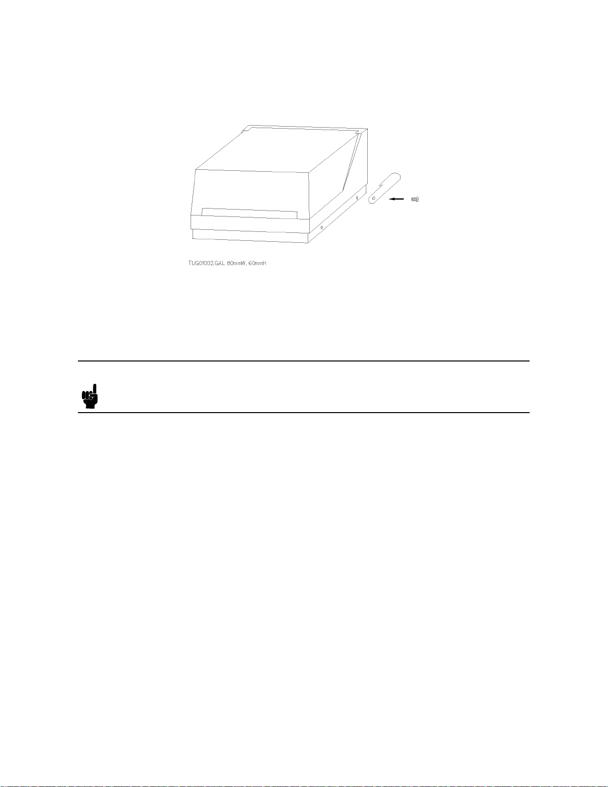
You can make the HP 16442A stable by installing stabilizers as shown in the following figure.
1. Put a stabilizer on both sides of test fixture.
2. Screw a flathead screw into hole of each stabilizer.
After installing stabilizers, connect terminals on the rear panel to the desired measurement
units.
Note
When you attach HP 16442A to HP 16440A SMU/Pulse Generator Selector
or HP 16441A R-Box, you do not need to install stabilizers . For attaching to
selector or R-Box procedure, see the User’s Guide for selector or R-Box.
HP 16442A User’s Gude 3

Operation
This section is organized into the following two sections:
Attaching a socket module onto HP 16442A.
Mounting and wiring DUT on the socket module.
Select the proper environment to execute the measurements. Place HP 16442A on a flat
surface. The HP 16442A shields from electromagnetic interference, but Hewlett-Packard
recommends that the measurement is performed in as noiseless environment as possible for
more stable and accurate measurement results.
You place the DUT into the provided socket modules in HP 16442A, then measure the dc
characteristics by using the connected measurement units.
Warning
Warning
Warning
Note
Caution
To prevent electric shock, be sure to connect the cable between the interlock
(Intlk) terminals of measurement instrument and HP 16442A before performing
measurements.
Do not operate HP 16442A while the High Voltage indicator is lit. Dangerous
voltages of up to 200 V may be present on the connection between
measurement units and DUT.
Do not get connection cables caught in the lid of HP 16442A during
measurements. Dangerous voltage of up to 200 V may be present on the
connection cables.
After setting up HP 16442A and DUT, confirm that the connections are
correct. Shut lid of HP 16442A to close switches of the interlock (Intlk)
terminal.
To prevent damage to instrument or DUT, do not remove or attach DUT in
HP 16442A when voltage or current is present.
Caution
Do not touch any metal surface that is in the circuit path. Oil, perspiration,
and dirt prevent good electric contact and degrade measurement accuracy.
4 HP 16442A User’s Gude

Circuit Schematic of HP 16442A Test Fixture
Figure 1-1 shows the circuit schematic of HP 16442A.
Figure 1-1. Circuit Schematic of HP 16442A Test Fixture
HP 16442A is equipped with an interlock (Intlk) terminal, which prevents the user from
getting an electric shock during operation.
If more than 40 V will be forced to HP 16442A, be sure to connect Intlk terminal of HP
16442A to Interlock terminal of measurement instrument using an Interlock/LED cable (HP
16493J option 001 for 1.5 m, HP 16493J option 002 for 3.0 m).
When the lid of HP 16442A is open, two switches of the Intlk terminal are open. The
instrument recognizes that the lid of HP 16442A is not closed and does not output high
voltage (more than ±40 V).
HP 16442A User’s Gude 5

The following figure shows pin assignment of the Intlk terminal.
6 HP 16442A User’s Gude

Attaching a Socket Module onto HP 16442A Test Fixture
After choosing correct socket module for DUT, install the socket module into HP 16442A.
The following figure shows how to attach socket module to HP 16442A. Use the following
procedure to attach the socket module:
1. Confirm that voltage or current is not forced to HP 16442A.
2. Open the lid of HP 16442A.
3. Check that the black plastic fasteners of the socket module are unlocked (pulled up).
4. Push the socket module onto HP 16442A.
5. Press the black fasteners down to lock the socket module into place.
Use the following procedure to remove a socket module from HP 16442A:
1. Confirm that voltage or current is not forced to HP 16442A.
2. Open the lid of HP 16442A.
3. Disconnect the connection cables.
4. Pull up the black plastic fasteners on both sides of the socket module.
5. Lift the socket module from HP 16442A.
HP 16442A User’s Gude 7

Mounting and Wiring the DUT on the Socket Module
Thirteen types of socket modules are available for mounting the DUTs:
Three socket modules for power devices.
Six socket modules for low power devices.
Three universal socket modules and a blank Teflon board module for uniquely shaped
devices.
1. Non-Kelvin Connections
Use connection cables to connect the FORCE terminals on HP 16442A to the FORCE
terminals on the socket module.
2. Kelvin Connections
Socket Modules for Power Devices
The three socket modules for power devices have separate FORCE and SENSE terminals
for Kelvin connections. As shown in the example in Figure 1-2, use miniature banana –
miniature banana connection cables to connect the FORCE and SENSE terminals of HP
16442A to the FORCE and SENSE terminals on the socket module.
Figure 1-2. Mounting DUT on Socket Module for Power Devices
8 HP 16442A User’s Gude

Socket Modules for Low Power Devices
The six socket modules for low power devices have FORCE terminals only. Up to 3 SMU
channels can be connected to DUT by Kelvin Connection. As shown in the example in
Figure 1-3, use miniature banana—pin plug connection cables to connect both FORCE
and SENSE terminals of HP 16442A to the FORCE terminal on the socket module as
follows: insert one pin plug into the FORCE terminal of the socket module, then insert
the other pin plug into the tail hole of the inserted pin plug.
Figure 1-3. Mounting DUT on Socket Module for Low Power Devices
To connect sense terminals as near as possible to the DUT, connect the SENSE
terminals of HP 16442A directly to the DUT with the miniature banana – miniature clip
connection cables as shown in following figure.
HP 16442A User’s Gude 9

3. Connections for a Uniquely Shaped Device
If there is no socket module suitable for a uniquely shaped DUT, you can connect the
device by using the following socket modules:
a. blank Teflon board
b. universal socket module
Blank Teflon Board
Connect all the terminals directly to the DUT on the blank Teflon board with the
miniature banana – miniature clip connection cables, as shown in the following figure.
Make sure to place the DUT on the blank Teflon board.
Universal Socket Module
The following figure shows an example of a universal socket module. You solder the
connection pins into the universal socket, then insert the pin plug of the connection cable
into the connection pin.
Note that hydrochloric acid residue deposited by solder may cause electrical problems.
Hewlett-Packard recommends that you solder the wiring on the universal board using low
hydrochloric acid solder (HP part number: 8090-0433).
Do not use the universal socket module for low-current measurements (less than 1 nA)
that require low leakage current.
10 HP 16442A User’s Gude

Maintenance
This section provides the following maintenance information:
Cleaning
Performing test
Servicing
Cleaning HP 16442A Test Fixture
To maintain high performance, HP 16442A must be kept clean. Oil, perspiration, hair, dust,
and dirt degrade board insulation, which increases leakage current and decreases measurement
accuracy.
Hewlett-Packard recommends the following cleaning procedure:
Chassis, lid, inner plate, and socket modules:
1. Make sure that voltage or current is not forced to HP 16442A.
2. Disconnect all cables from HP 16442A.
3. Using lint-free paper, gently wipe the chassis, lid, inner plate, and socket module. For
any area that will not come clean, dip the lint-free paper into alcohol and wipe the area
gently.
Connection cables:
1. Make sure that voltage or current is not forced to HP 16442A.
2. Disconnect the connection cables from HP 16442A.
3. Dip lint-free paper into alcohol and gently wipe the metal contacts of the connection
cables.
HP 16442A User’s Gude 11

Performing the Interlock Circuit Test
To confirm that interlock circuit test, do as follows:
1. Connect the Intlk terminal of HP 4155/4156 to your interlock circuit.
2.
Press
System
front-panel key, then select
NNNNNNNNNNNNNNNNNNNNNNNNNNNNNNNN
CALIB/DIAG primary softkey to display the
SYSTEM: SELF-CALIBRATION/DIAGNOSTICS page.
3.
In the CALIB/DIAG field, select
4.
In the CATEGORY field, select
NNNNNNNNNNNNNN
DIAG secondary softkey.
NNNNNNNNNNNNNNNNNNNNNNNNNNNNNNNNNNNNNN
I/O & PERIPH secondary softkey.
5. Move pointer to the 403 (INT.) Interlock & LED field.
6.
Select
NNNNNNNNNNNNNNNNNNNNNNN
EXECUTE secondary softkey.
7. Confirm the following:
LED turns on within 1 sec from when interlock circuit is shorted.
LED turns off within 1 sec from when interlock circuit is open.
8.
To stop the interlock test, select
NNNNNNNNNNNNNN
STOP
secondary softkey.
Servicing the Test Fixture
This section provides information for trained service personnel to repair the test fixture.
”Replaceable Parts” provides the HP part numbers of replaceable parts. When a part needs
to be replaced, order the parts from the nearest HP Sales and Service Office.
Warning
High voltages may be present in the test fixture when voltage or current is
added to the test fixture. Dangerous voltage may be generated on wires or
parts and the danger of electric shock exists.
Make sure that terminals are not connected to the instruments before you repair the
test fixture. When you remove the bottom cover, loosen the four flathead screws using a
screwdriver, as shown in Figure 1-4.
12 HP 16442A User’s Gude
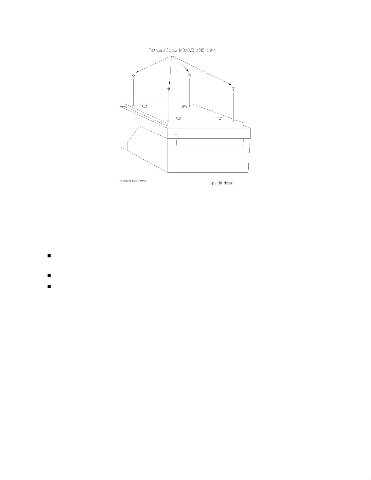
Figure 1-4. Removing the Bottom Cover
When wiring the test fixture and socket modules, use low hydrochloric acid solder (HP part
number: 8090-0433) to prevent the flux in the solder from spreading unnecessarily. When
soldering, make sure the terminals do not make contact with each other. After soldering,
make sure that there are no lint bridges so that leakage current is minimal.
Keep the following items in mind when repairing socket modules:
Place a ferrite bead at the 8 mm point of the terminal on the socket side and fix the bead
using epoxy adhesive.
Never allow the ferrite beads to make contact with each other.
For the three socket modules used for power devices, wrap the contact of the wire and
socket terminal using heat-shrink tube (HP part number: 0890-1496).
HP 16442A User’s Gude 13

Replaceable Parts
Figure 1-5. View of Cable Connections in the Test Fixture
14 HP 16442A User’s Gude

Table 1-1. Parts List of Cable Connections in the Test Fixture
Reference
Designation
(1) 3101-3241 2 Sense Switch
(2) 1450-0641 1 LED
(3) 8150-0459 40cm×1 Wire 24 White/Red
(4) 8150-0460 40cm×2 Wire 24 White/Orange
(5) 0535-0031 4 Nut
(6) 8150-4684 32cm×1 Wire 24 Orange
(7) 8150-4682 32cm×1 Wire 24 Brown
(8) 8150-4683 32cm×1 Wire 24 Red
(9) 8150-4685 32cm×1 Wire 24 Yellow
(10) 8120-0102 22cm×2, 15cm×6 Coaxial Cable 50Ω
(11) 8150-0462 40cm×1 Wire 24 White/Green
(12) 8150-0458 30cm×8 Wire 24 White/Brown
(13) 8150-0462 32cm×1 Wire 24 White/Yellow
(14) 8120-0122 16cm×1 Coaxial Cable
(15) 8120-0122 16cm×1 Coaxial Cable
(16) 8150-0456 5cm×4 Wire 24 White
(17) 41422-24099 1 Soldering Pipe
HP Part Number Quantity Description
HP 16442A User’s Gude 15
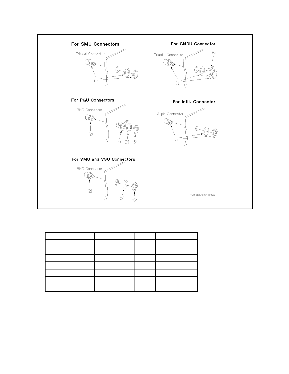
Figure 1-6. How to Install Triaxial and BNC Connectors
Table 1-2. Parts List for Connectors
Reference Designation HP Part Number Quantity Description
(1) 1250-1906 7 Triaxial Connector
(2) 1250-0083 6 BNC Connector
(3) 2190-0016 6 Lock Washer
(4) 0360-1190 2 Terminal Washer
(5) 2950-0001 6 Nut
(6) 5000-4218 1 Terminal Washer
(7) 1252-1419 1 6-pin Connector
16 HP 16442A User’s Gude
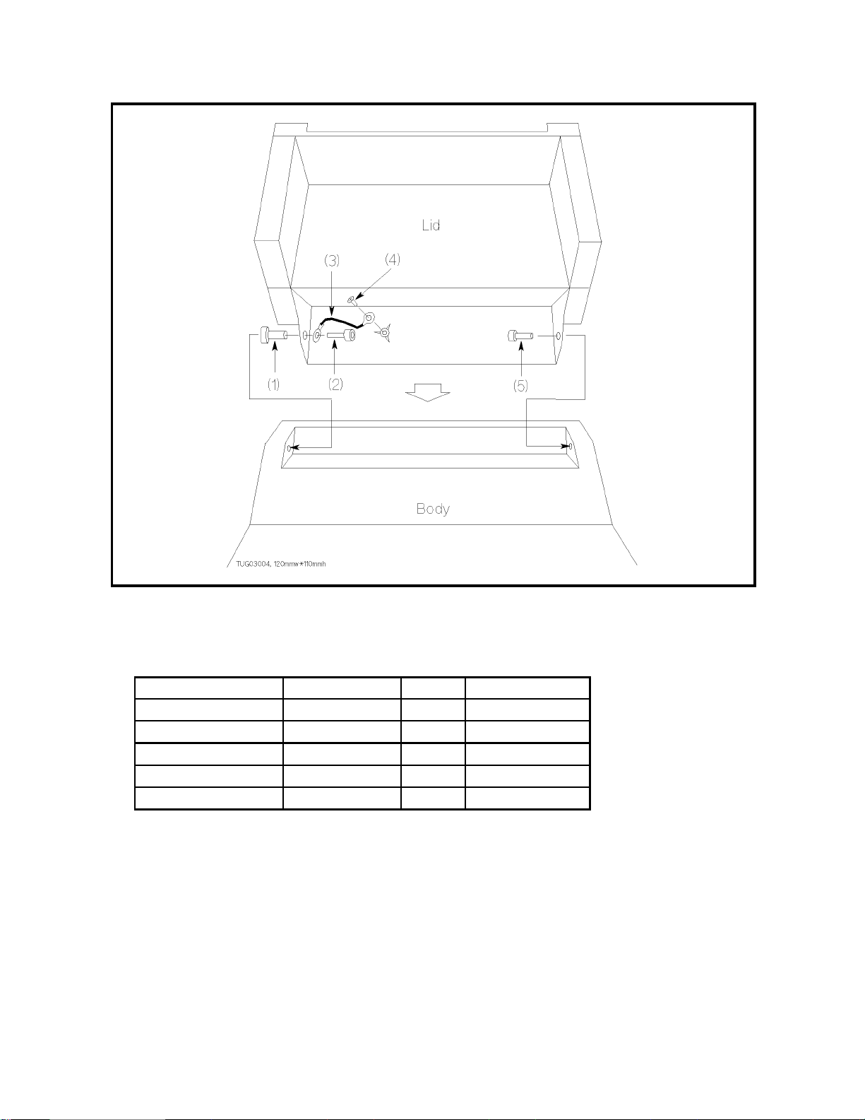
Figure 1-7. Connections between Lid and Body
Table 1-3.
Parts List for Connections between Lid and Body
Reference Designation HP Part Number Quantity Description
(1) 16442-24001 1 Sleeve
(2) 0515-1973 1 Bolt M4
(3) 16442-61624 1 Cable Assy
(4) 0515-1550 1 Screw M3-L 8 P-H
(5) 16442-23001 1 Pin
HP 16442A User’s Gude 17

Figure 1-8. TO-3 or TO-66 Package Socket Module
Figure 1-9. In-Line Package Socket Module
Figure 1-10. Axial Lead Package Socket Module
18 HP 16442A User’s Gude
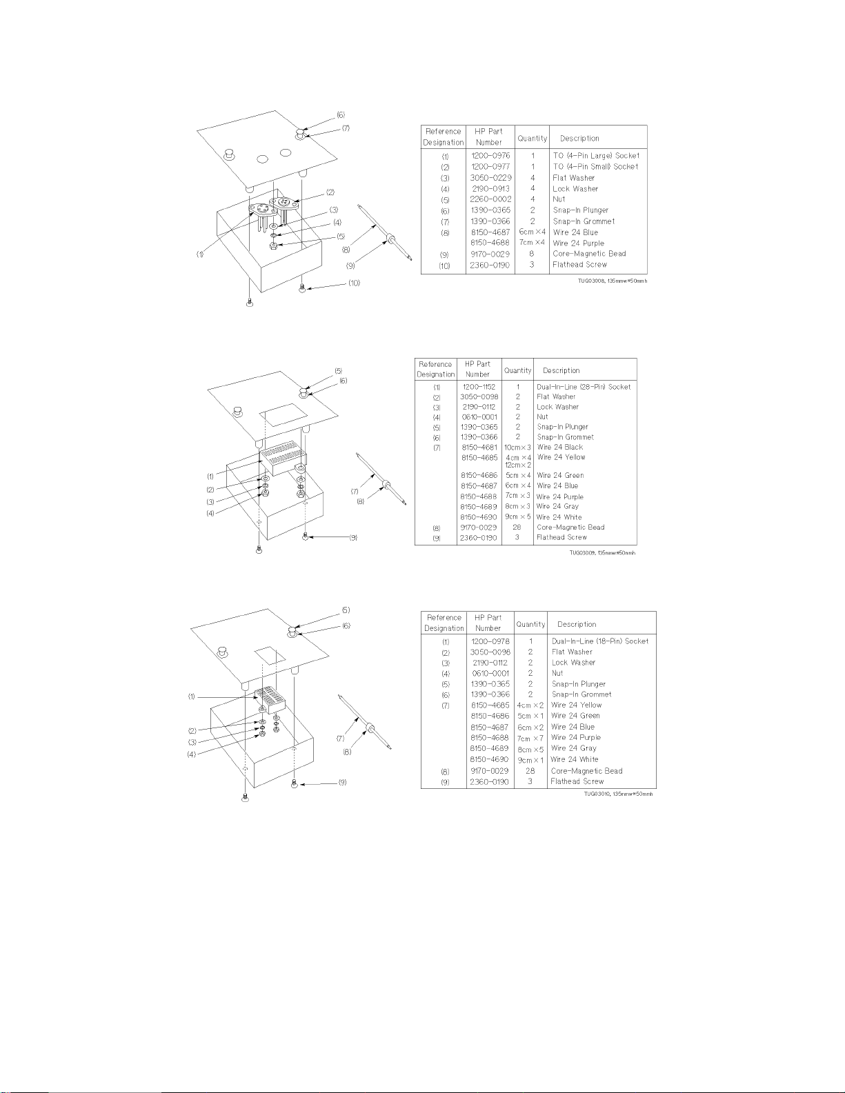
Figure 1-11. TO- (4-pin) Package Socket Module
Figure 1-12. Dual-In-Line (28-pin) Package Socket Module
Figure 1-13. Dual-In-Line (18-pin) Package Socket Module
HP 16442A User’s Gude 19

Figure 1-14. TO- (8-, 10-, and 12-pin) Package Socket Module
Figure 1-15. Universal Socket Module
20 HP 16442A User’s Gude

Specifications
The ”supplemental information” and ”typical” entries, in the following specifications are
not warranted, but provide useful information about the functions and performance of the
instruments.
The following specifications data is specified at 23 ±5
Functions
HP 16442A lets you test various shaped DUTs. HP 16442A has:
6 SMU channels (when using non-Kelvin connections).
3 SMU channels (when using Kelvin connections).
2 VSU channels.
2 VMU channels.
2 PGU channels.
1 GNDU channel.
interlock (Intlk) 6-pin connector.
Voltage and current range
◦
C and 50 % relative humidity.
Channel Maximum Voltage Maximum Current
SMU 200 V 1A
VSU 40 V 100 mA
VMU 40 V —
PGU 40 V 200 mA (AC peak)
GNDU 40 V 1.6 A
HP 16442A User’s Gude 21

General Information | Accessories (furnished)
HP Part Number Quantity Description
16442-60101 1 carrying case for socket modules
16442-60002 2 stabilizer
16442-61600 4 miniature banana – pin plug connection cable (black)
16442-61601 4 miniature banana – pin plug connection cable (red)
16442-61602 4 miniature banana – pin plug connection cable (blue)
16442-61603 3 pin plug – pin plug connection cable (black)
16442-61604 3 pin plug – pin plug connection cable (red)
16442-61605 3 pin plug – pin plug connection cable (blue)
16442-61606 3 miniature banana – miniature clip connection cable (black)
16442-61607 3 miniature banana – miniature clip connection cable (red)
16442-61608 3 miniature banana – miniature clip connection cable (blue)
16442-61609 3 miniature banana – miniature banana connection cable (black)
16442-61610 3 miniature banana – miniature banana connection cable (red)
16442-61611 3 miniature banana – miniature banana connection cable (blue)
16058-60004 1 blank TeflonTMboard
16088-60002 1 dual-in-line package socket module (28-pin)
16088-60009 1 axial lead package socket module
16088-60006 1 TO-package socket module (12-pin)
16442-90000 1 HP 16442A test fixture User’s Guide (this document)
1
1 Two f athead screws are furnished.
Connection cables (furnished)
Miniature Banana – Pin Plug
22 HP 16442A User’s Gude

Pin Plug – Pin Plug
Miniature Banana – Miniature Clip
Miniature Banana – Miniature Banana
HP 16442A User’s Gude 23

Socket modules (furnished)
Blank Teflon Board
Dual-In-Line Packages (28-pin)
24 HP 16442A User’s Gude

Axial lead package
TO-Package (12-pin)
HP 16442A User’s Gude 25

General Information | Accessories (optional)
Option
Number
010 adds four 1.5 m triaxial cables 16058-61603
and four triax caps 1250-1708
011 adds four 3.0 m triaxial cables 04145-61622
and four triax caps 1250-1708
800 adds blank TeflonTMboard 16058-60004
801 adds universal socket module (0.1 inch pitch) 16088-60010
and ten connection pins 16088-60013
802 adds universal socket module (0.075 inch pitch) 16442-60011
and ten connection pins 16088-60013
803 adds universal socket module (0.05 inch pitch) 16442-60012
and ten connection pins 16088-60013
810 adds ten connection pins for universal socket module 16088-60013
811 adds 6 miniature banana – pin plug connection cables
black × 2 16442-61600
red × 2 16442-61601
blue × 2 16442-61602
812 adds 6 pin plug – pin plug connection cables
black × 2 16442-61603
red × 2 16442-61604
blue × 2 16442-61605
813 adds 6 miniature banana – miniature clip connection cable
black × 2 16442-61606
red × 2 16442-61607
blue × 2 16442-61608
814 adds 6 miniature banana – miniature banana connection cables
black × 2 16442-61609
red × 2 16442-61610
blue × 2 16442-61611
821
822 adds dual-in-line package socket module (18-pin) 16088-60003
823 adds dual-in-line package socket module (28-pin) 16088-60002
824 adds TO-packages socket module (8-pin) 16088-60004
825 adds TO-packages socket module (10-pin) 16088-60005
826 adds TO-packages socket module (12-pin) 16088-60006
830 adds TO-packages socket module (TO-3 or TO-66) 16088-60007
831 adds in-line packages socket module (3-pin) 16088-60008
832 adds axial lead package socket module 16088-60009
890 adds carrying case for socket modules 16442-60101
adds TO-packages socket module (4-pin) 16088-60001
Description HP Part
Number
26 HP 16442A User’s Gude

Connection pins (optional)
Socket modules (optional)
TO-package (TO-3 or TO-66)
In-Line package (3-pin)
HP 16442A User’s Gude 27
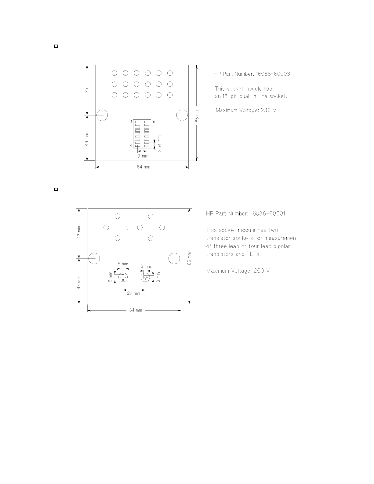
Dual-In-Line package (18-pin)
TO-package (4-pin)
28 HP 16442A User’s Gude

TO-package (8-pin)
TO-package (10-pin)
HP 16442A User’s Gude 29
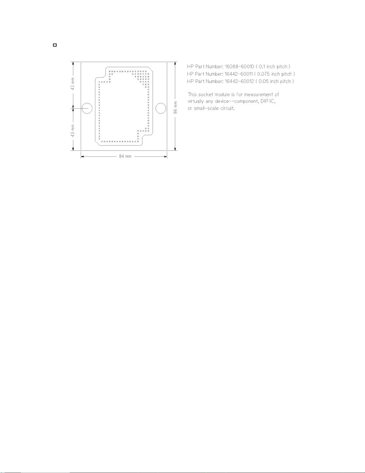
Universal socket module
30 HP 16442A User’s Gude

General Specifications
Environment
Operating temperature 5◦Cto40◦C
◦
Storage temperature −40
Operating Humidity 5% to 80% relative humidity (at no condensation)
Storage Humidity 5% to 90% relative humidity at 65
Weight
Approximately 2.5 kg
Dimensions (W × H × D)
260 mm × 140 mm × 260 mm (not including stabilizers)
260 mm × 140 mm × 320 mm (including stabilizers)
Cto70◦C
◦
C
HP 16442A User’s Gude 31

Supplemental Information
The following reference data is specified at 23 ± 5◦C and 50 % relative humidity.
SMU channel
Leakage Current (force or sense ←→ common) 10 pA maximum at 200 V
Stray Capacitance (force or sense ←→ common) 15 pF maximum
Stray Capacitance (force or sense ←→ other SMUs) 3 pF typical
Residual Resistance (force) 60 mΩ typical
Residual Resistance (sense) 60 mΩ typical
Guard Capacitance (force or sense ←→ guard) 70 pF maximum
VSU channel
Residual Resistance 60 mΩ typical
VMU channel
Residual Resistance 60 mΩ typical
PGU channel
Characteristic Impedance 50 Ω typical
GNDU channel
Residual Resistance (force) 40 mΩ typical
Residual Resistance (sense) 40 mΩ typical
Socket Board
Parts number Description Max Voltage Residual Resistance
16088-60001 2 Tr 200 V
16088-60002 28pin DIP 230 V
16088-60003 18pin DIP 230 V
16088-60004 8pin TO 230 V
16088-60005 10pin TO 200 V
16088-60006 12pin DIP 230 V
16088-60007 TO-3,TO-66 1000 V 20 mΩ
16088-60008 3pin Kelvin 1000 V 20 mΩ
16088-60009 axial Kelvin 1000 V 20 mΩ
16088-60010 Universal module
16442-60011 Universal module
16442-60012 Universal module
Connection wire residual resistance : 20 mΩ typical
32 HP 16442A User’s Gude
 Loading...